KR100723060B1 - Portable terminal with flash light intensity control function - Google Patents
Portable terminal with flash light intensity control functionDownload PDFInfo
- Publication number
- KR100723060B1 KR100723060B1KR1020050076887AKR20050076887AKR100723060B1KR 100723060 B1KR100723060 B1KR 100723060B1KR 1020050076887 AKR1020050076887 AKR 1020050076887AKR 20050076887 AKR20050076887 AKR 20050076887AKR 100723060 B1KR100723060 B1KR 100723060B1
- Authority
- KR
- South Korea
- Prior art keywords
- image data
- flash
- image
- unit
- luminance information
- Prior art date
- Legal status (The legal status is an assumption and is not a legal conclusion. Google has not performed a legal analysis and makes no representation as to the accuracy of the status listed.)
- Expired - Fee Related
Links
Images


Classifications
- H—ELECTRICITY
- H04—ELECTRIC COMMUNICATION TECHNIQUE
- H04N—PICTORIAL COMMUNICATION, e.g. TELEVISION
- H04N23/00—Cameras or camera modules comprising electronic image sensors; Control thereof
- H04N23/70—Circuitry for compensating brightness variation in the scene
- H04N23/75—Circuitry for compensating brightness variation in the scene by influencing optical camera components
- H—ELECTRICITY
- H04—ELECTRIC COMMUNICATION TECHNIQUE
- H04N—PICTORIAL COMMUNICATION, e.g. TELEVISION
- H04N23/00—Cameras or camera modules comprising electronic image sensors; Control thereof
- H04N23/56—Cameras or camera modules comprising electronic image sensors; Control thereof provided with illuminating means
- H—ELECTRICITY
- H04—ELECTRIC COMMUNICATION TECHNIQUE
- H04N—PICTORIAL COMMUNICATION, e.g. TELEVISION
- H04N23/00—Cameras or camera modules comprising electronic image sensors; Control thereof
- H04N23/57—Mechanical or electrical details of cameras or camera modules specially adapted for being embedded in other devices
- H—ELECTRICITY
- H04—ELECTRIC COMMUNICATION TECHNIQUE
- H04N—PICTORIAL COMMUNICATION, e.g. TELEVISION
- H04N25/00—Circuitry of solid-state image sensors [SSIS]; Control thereof
Landscapes
- Engineering & Computer Science (AREA)
- Multimedia (AREA)
- Signal Processing (AREA)
- Studio Devices (AREA)
- Stroboscope Apparatuses (AREA)
Abstract
Translated fromKoreanDescription
Translated fromKorean도 1은 종래의 플래시 제어 기능을 구비한 휴대용 단말기의 블록도.1 is a block diagram of a conventional portable terminal having a flash control function.
도 2a는 본 발명의 바람직한 일 실시예에 따른 카메라 기능을 구비한 휴대용 단말기의 블록도.FIG. 2A is a block diagram of a portable terminal having a camera function according to a preferred embodiment of the present invention; FIG.
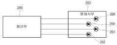
도 2b는 본 발명의 바람직한 일 실시예에 따른 제어부와 플래시부의 결합을 나타낸 도면.2B illustrates a combination of a control unit and a flash unit according to a preferred embodiment of the present invention.
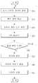
도 3은 본 발명의 바람직한 일 실시예에 따른 휴대용 단말기의 이미지 센서에 촬상되는 외부 영상에 상응하는 휘도 성분을 이용하여 플래시의 광량을 조절하는 방법을 나타낸 순서도.3 is a flowchart illustrating a method of adjusting a light amount of a flash using a luminance component corresponding to an external image captured by an image sensor of a portable terminal according to a preferred embodiment of the present invention.
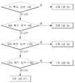
도 4는 본 발명의 바람직한 일 실시예에 따른 제어부의 휘도 정보에 따른 플래시 제어 신호를 생성하는 방법을 나타낸 순서도.4 is a flowchart illustrating a method of generating a flash control signal according to luminance information of a controller according to an exemplary embodiment of the present invention.
도 5는 본 발명의 바람직한 일 실시예에 따른 휘도(Luminance) 정보의 범위에 대응되도록 조도 정보를 매핑하여 저장하고 있는 조도 정보 매핑 테이블.FIG. 5 is a schematic diagram illustrating an illumination information mapping table in which illumination information is mapped to correspond to a range of luminance information according to a preferred embodiment of the present invention.
<도면의 주요부분에 대한 부호의 설명>Description of the Related Art
210 : 렌즈부210:
220 : 이미지 센서220: Image sensor
230 : 신호 처리부230: Signal processor
240 : 입력부240: input unit
250 : 저장부250:
260 : 플래시부260:
270 : 표시부270:
280 : 제어부280:
본 발명은 휴대용 단말기에 관한 것으로, 특히 영상 촬영을 위해 플래시의 광량을 조절할 수 있는 휴대용 단말기에 관한 것이다.BACKGROUND OF THE
정보통신 기술의 발전으로 인해 전자 제품에 부품들이 점점더 소형화, 집적화되고 있다. 이로 인해, 휴대용 단말기도 다양한 멀티미디어 기능(예를 들어, 동영상, MP3), 카메라 기능, 무선 인터넷 등등 많은 기능이 통합된 통합 기기의 형태로 발전하고 있다.Components of electronic products are becoming smaller and more integrated due to the development of information and communication technologies. As a result, portable terminals are being developed in the form of integrated devices in which many functions such as various multimedia functions (for example, video, MP3), camera functions, wireless Internet, and the like are integrated.
도 1은 종래의 카메라 기능을 구비한 휴대용 단말기의 블록도를 간단하게 예시한 도면이다. 도 1을 참조하여 종래의 휴대용 단말기의 플래시 제어 방법을 간략 히 설명하면, 휴대용 단말기에 구비된 입력부(110)를 통해 사용자로부터 플래시부(140)의 온(On)/오프(Off)에 상응하는 명령이 입력되면, 제어부(160)는 LED(Light Emitting Diode)를 온(On)/오프(Off)시키기 위한 제어 신호를 플래시부(140)로 전달하였다. 이와 같이, 종래에는 사용자로부터 LED 온(on)/오프(Off)에 상응하는 명령을 입력받아, 플래시부(140)에 포함된 LED를 온(On)/오프(Off) 시켰다. 이로 인해, 카메라 기능을 구비한 휴대용 단말기를 이용하여 피사체 촬영시 주변의 조도에 상관없이 항상 일정한 광량만을 발산하여 주변 환경을 고려한 적절한 촬영이 불가능하였다. 이는 사용자에게 플래시를 내장한 휴대용 단말기의 플래시 기능이 불필요한 기능으로 인식되도록 하며, 나아가 제품에 대한 신뢰도를 떨어뜨리게 하였다.1 is a block diagram of a conventional portable terminal having a camera function. Referring to FIG. 1, a flash control method of a conventional portable terminal will be briefly described. Referring to FIG. 1, a method of controlling a flash according to an embodiment of the present invention will be described. The
또한, 종래에는 플래시부(140)에 포함된 LED를 발광시키기 위해 사용자로부터 플래시부(140)의 동작을 개시를 지시하기 위한 명령을 구비된 입력부(110)를 통해 입력받아야만 하는 불편함이 있었다.In addition, in order to illuminate the LED included in the
따라서, 상술한 문제점을 해결하기 위한 본 발명의 목적은 피사체 촬영시 이미지 센서에 결상된 광상의 휘도 정보를 이용하여 조도의 정도를 판단하여 플래시의 광량을 조절할 수 있는 플래시 광량 조절 기능을 구비한 휴대용 단말기를 제공하는 것이다.SUMMARY OF THE INVENTION Accordingly, it is an object of the present invention to solve the above-mentioned problems and to provide a portable light emitting device having a flash light amount control function capable of controlling the light amount of a flash by determining the degree of illumination using luminance information of a light image formed on an image sensor, Thereby providing a terminal.
본 발명의 다른 목적은 자동으로 플래시의 광량을 조절하여 적절한 광량을 피사체에 발산하여 고품질의 영상을 촬상할 수 있는 플래시 광량 조절 기능을 구비한 휴대용 단말기를 제공하는 것이다.It is another object of the present invention to provide a portable terminal having a flash light amount control function capable of automatically radiating an appropriate amount of light to a subject to capture a high quality image.
상기 목적을 달성하기 위하여, 본 발명의 일 측면에 따르면, 이미지 센서를 통해 결상된 광상에 상응하는 영상 데이터의 휘도(Luminance) 정보를 이용하여 조도의 정도를 결정하여 플래시의 광량을 자동으로 조절할 수 있는 플래시 광량 조절 기능을 구비한 휴대용 단말기가 제공된다.According to an aspect of the present invention, there is provided a method of adjusting a light amount of a flash light source, the method comprising: determining a degree of illumination using luminance information of image data corresponding to a light image formed through an image sensor; A portable terminal having a flash light amount control function is provided.
본 발명의 바람직한 일 실시예에 따르면, 외부 영상에 상응하는 빛을 결상하여 원시 이미지 데이터로 변환하는 이미지 센서; 상기 원시 이미지 데이터를 이용하여 휘도(Luminance) 정보를 생성하는 신호 처리부; 상기 휘도(Luminance) 정보를 정해진 조도 정보와 비교하여 상기 외부 영상의 조도 정도를 결정하고 상기 조도 정도에 따라 플래시 제어 신호를 생성하는 제어부; 및 상기 플래시 제어 신호에 의해 독립적으로 온(On) 또는 오프(Off)되는 복수의 LED를 포함하는 플래시부를 포함하는 플래시 광량 조절 기능을 구비한 휴대용 단말기가 제공된다.According to a preferred embodiment of the present invention, there is provided an image processing apparatus comprising: an image sensor for forming an image of light corresponding to an external image and converting the image into raw image data; A signal processor for generating luminance information using the raw image data; A controller for comparing the luminance information with predetermined luminance information to determine a luminance level of the external image and generating a flash control signal according to the luminance level; And a flash unit including a plurality of LEDs that are independently turned on or off by the flash control signal.
상기 신호 처리부는 상기 원시 이미지 데이터를 미리 정해진 이미지 데이터로 변환하며, 상기 제어부의 제어에 의해 상기 이미지 데이터를 저장하는 저장부를 더 포함할 수 있다. The signal processing unit may further include a storage unit that converts the raw image data into predetermined image data and stores the image data under the control of the control unit.
상기 제어부의 제어에 의해 상기 이미지 데이터를 디스플레이하는 표시부를 더 포함할 수 있다.And a display unit for displaying the image data under the control of the control unit.
상기 외부 영상을 촬영하거나 미리 보기 기능 선택 명령을 입력받는 입력부를 더 포함할 수 있다.And an input unit for photographing the external image or receiving a preview function selection command.
상기 원시 이미지 데이터는 YUV 형식으로 표현된 데이터이며, 상기 신호 처리부는 상기 YUV 형식의 원시 이미지 데이터를 RGB 형식으로 변환할 수 있다.The raw image data is data expressed in YUV format, and the signal processing unit can convert the YUV format raw image data into RGB format.
상기 신호 처리부는 8비트로 표현된 상기 원시 이미지 데이터를 각각 5비트의 R(Red), 6비트의 G(Green), 5비트의 B(Blue) 데이터로 변환할 수 있다.The signal processor may convert the raw image data represented by 8 bits into R (Red) of 5 bits, G (Green) of 6 bits, and B (Blue) data of 5 bits.
상기 휘도 정보는 상기 YUV 형식의 상기 원시 이미지 데이터의 Y 성분들의 평균 값이고, 상기 조도 정보는 상기 휘도 정보에 대응하여 온(On) 또는 오프(Off) 될 상기 LED의 개수일 수 있다.The luminance information may be an average value of Y components of the YUV format raw image data, and the luminance information may be the number of the LEDs to be turned on or off according to the luminance information.
이하, 본 발명의 바람직한 실시예를 첨부한 도면들을 참조하여 상세히 설명하기로 한다.Hereinafter, preferred embodiments of the present invention will be described in detail with reference to the accompanying drawings.
도 2는 본 발명의 바람직한 일 실시예에 따른 카메라 기능을 구비한 휴대용 단말기의 블록도이다. 본 발명은 이미지 센서를 통해 피사체에 상응하여 결상된 영상 정보에서 영상의 휘도 정보를 분석하여 플래시의 광량을 자동으로 조절할 수 있다. 이하에서는 결상된 영상의 휘도 정보를 분석하여 플래시의 광량을 자동 조절하는 것을 중점으로 설명하고 있으나, 이미지 센서를 통해 유입되는 빛의 세기를 분석하여 플래시의 광량을 자동 조절할 수도 있다. 또한, 이하에서는 본 발명에 따른 휴대용 단말기가 촬영 모드, 일반 모드 등의 모드에 상응하는 명령을 구비된 입력 부(240)를 통해 입력받을 수 있으며, 촬영 모드에 상응하는 모드 선택 명령을 입력부(240)를 통해 입력받아 상응하는 동작을 촬영 모드에 상응하는 동작(예를 들어, 이미지 센서를 통해 결상된 영상을 표시부(270)를 통해 미리 보기, 줌인/줌아웃(Zoom in/Zoom out) 등)을 수행할 수 있는 것을 가정하여 설명하도록 한다. 또한, 본 명세서에서는 플래시부(260)에 포함된 LED가 4개인 것을 중점으로 설명하고 있으나, 플래시부(260)에 포함된 LED가 두개 이상인 경우 동일하게 적용될 수 있다.2 is a block diagram of a portable terminal having a camera function according to a preferred embodiment of the present invention. The present invention can automatically adjust the light amount of the flash by analyzing the brightness information of the image in the image information formed in accordance with the subject through the image sensor. The following description focuses on the automatic adjustment of the light intensity of the flash by analyzing the luminance information of the image formed. However, the light intensity of the flash can be automatically adjusted by analyzing the light intensity inputted through the image sensor. Hereinafter, the portable terminal according to the present invention may receive input through an
도 2a에서 보여지는 바와 같이, 본 발명에 따른 휴대용 단말기(200)는 렌즈부(210), 이미지 센서(220), 신호 처리부(230), 입력부(240), 저장부(250), 플래시부(260), 표시부(270), 제어부(280)를 포함하여 구성된다.2A, a portable terminal 200 according to the present invention includes a
렌즈부(210)는 이미지 센서(220) 전단에 구비되어 피사체의 수광을 수행하는 수단이다.The
이미지 센서(220)는 렌즈부(210)로부터 외부 영상에 상응하는 광상이 결상되는 촬상 소자로서, 광상에 관한 빛 신호를 전기 신호인 아날로그 신호로 변환하고, 이를 이미지 센서(220)에 포함된 A/D 컨버터(미도시)를 통해 디지털 신호로 변환한다. 예를 들어, 이미지 센서(220)는 전하결합소자(CCD : Charge Coupled Device, 이하에서는 "CCD"라 칭함) 또는 상보성금속산화물 반도체(CMOS : Complementary Metal Oxide Semiconductor, 이하에서는 "CMOS"라 칭함)로 구현될 수 있다.The
예를 들어, 이미지 센서(220)는 빛 신호가 변환되어 수집된 각 픽셀의 베이어 데이터(RGB데이터)를 신호 처리부(230)로 출력할 수 있다. 이미지 센서(220)에 는 RGB를 각각 인식하는 필터를 갖는 픽셀이 배치되는데 RGB 필터는 총 픽셀 수에서 사람 눈에 민감한 녹색을 50%, 적색 및 청색이 25%가 되도록 하는 베이어 패턴에 따라 배치될 수 있다. 이러한 베이어 패턴을 갖는 이미지 센서(220)에서 출력되는 데이터를 베이어 데이터라고 하며, 이와 같은 베이어 데이터를 이미지 센서(220)에 포함된 이미지 신호 처리부(ISP : Image Signal Process, 미도시)를 통해 예를 들어, 8비트 YUV 신호로 변환되어 신호 처리부(230)로 전달할 수 있다.For example, the
이하에서는 이미지 센서(220)에서 신호 처리부(230)로 출력되는 신호를 "원시 이미지 데이터"로 정의한다.Hereinafter, a signal output from the
또한, 이미지 센서(220)에 포함된 이미지 신호 처리부(ISP)를 통해 획득된 이미지에 대한 인터폴레이션(Interpolation), 자동 화이트 밸런스(auto white balance), 감마 보정(Gamma correction), 밝기 보정(Brightness correction), 색 보정(Color correction), 색 영역 변환(Color space conversion) 등을 수행할 수도 있다. 예를 들어, 이미지 신호 처리부(ISP)는 YUV 신호를 4:2:2 또는 4:2:0 포맷으로 압축하여 처리할 수 있다. YUV 신호를 4:2:2 또는 4:2:0 포맷으로 압축 처리하는 방법은 당업자에게는 자명한 사항이므로 이에 대한 설명은 생략하기로 한다.Interpolation, auto white balance, gamma correction, and brightness correction for an image obtained through an image signal processor (ISP) , Color correction, color space conversion, and the like. For example, an image signal processing unit (ISP) can compress and process a YUV signal in 4: 2: 2 or 4: 2: 0 format. A method of compressing a YUV signal in a 4: 2: 2 format or a 4: 2: 0 format will be obvious to those skilled in the art and a description thereof will be omitted.
본 명세서에서는 이미지 센서(220)에 이미지 신호 처리부(ISP)가 포함되어 있는 것을 가정하여 설명하고 있으나, 이미지 신호 처리부(ISP)는 이미지 센서(220)와 별도로 독립적인 구성 요소로 존재할 수도 있다.Although an image signal processing unit (ISP) is included in the
신호 처리부(230)는 이미지 센서(220)로부터 입력된 원시 이미지 데이터를 미리 정해진 이미지 포맷으로 변환하여(이하에서는 신호 처리부(230)에서 원시 이 미지 데이터를 미리 정해진 이미지 포맷으로 변환하여 출력하는 데이터를 "이미지 데이터"로 칭한다) 제어부(280)로 전달한다. 또한, 신호 처리부(230)는 이미지 센서(220)로부터 입력된 원시 이미지 데이터를 이용하여 휘도(Luminance) 정보를 생성하여 제어부(280)로 전달할 수 있다. 또한, 신호 처리부(230)는 이미지 센서(220)로부터 입력된 원시 이미지 데이터를 미리 정해진 이미지 형식으로 변환하여 제어부(280)로 전달할 수도 있다.The
예를 들어, 신호 처리부(230)는 이미지 센서(220)로부터 YUV 형식의 원시 이미지 데이터가 입력되면, 원시 이미지 데이터를 예를 들어, 하기 수학식1을 이용하여 RGB 형식으로 변환할 수 있다. 또한, RGB 형식으로 변환된 원시 이미지 데이터를, 예를 들어 미리 정해진 이미지 포맷이 JPEG이라면, JPEG 이미지 포맷으로 복호화 또는 부호화(encoding or decoding)를 수행할 수 있다. 또한 신호 처리부(230)는 이미지를 확대, 축소, 로테이션(rotation) 등을 수행할 수도 있다.For example, when the original image data of the YUV format is input from the
G = Y + 0.272U + 0.647VG = Y + 0.272U + 0.647V
B = Y + 1.1061U + 1.703VB = Y + 1.1061U + 1.703V
예를 들어, 휴대용 단말기(200)에서 표시부(270)로 데이터를 출력하기 위한 데이터 라인이 16비트 데이터 라인인 경우, 신호 처리부(230)는 이미지 센서(220)로부터 8비트 YUV 신호를 입력받아 각각 5비트, 6비트, 5비트의 RGB 신호로 변환할 수 있다.For example, when the data line for outputting data from the portable terminal 200 to the
또한, 예를 들어 신호 처리부(230)는 이미지 센서(220)로부터 입력된 원시 이미지 데이터의 휘도(Luminance) 신호(즉, YUV 형식의 원시 이미지 데이터의 Y 성분의)의 평균값으로 휘도(Luminance) 정보를 산출하여 제어부(280)로 전달할 수도 있다.For example, the
또 다른 예를 들어, 신호 처리부(230)는 이미지 센서(220)에 포함된 이미지 신호 처리부(ISP)의 밝기 정보에 상응하여 갱신되도록 설정된 내부 레지스터(미도시)에서 휘도 정보를 독출하여 제어부(280)로 전달할 수도 있다.For example, the
입력부(240)는 사용자로부터 휴대용 단말기(200)의 동작을 제어하기 위한 제어 명령, 선택 명령(예를 들어, 휴대용 단말기의 모드 선택 명령, 휴대용 단말기의 기능 선택 명령(예를 들어, 사진 촬영, 동영상 녹화 등) 등) 등을 입력받기 위한 수단이다. 예를 들어, 키 입력부(110)는 복수의 키 버튼(예를 들어, 숫자/문자 키, * 또는 #의 기호 키, 하나 이상의 기능 키(예를 들어, 메뉴키, 통화 키, 확인키, 무선 인터넷 접속을 위한 키 등))으로 구현되거나 터치 스크린 등의 형태로 구현될 수 있다.The
저장부(250)는 휴대용 단말기(200)의 운용 프로그램, 조도 정보 매핑 테이블, 이미지 센서(220)를 통해 촬상된 외부 영상에 상응하는 이미지 데이터 등이 저장된다.The
플래시부(260)는 복수의 LED(Light Emitting Diode)를 포함하며, 제어부(280)로부터 입력되는 플래시 제어 신호에 상응하여 독립적으로 LED가 온(On) 또는 오프(Off)되도록 한다.The
표시부(270)는 신호 처리부(230)로부터 입력된 이미지 데이터를 디스플레이하는 수단이다. 예를 들어, 표시부(270)는 액정화면(LCD : Liquid Crystal Display) 일 수 있다.The
제어부(280)는 신호 처리부(230)로부터 입력되는 휘도(Luminance) 정보를 휘도(Luminance) 정보의 범위에 대응되도록 조도 정보를 매핑하여 저장하고 있는 조도 정보 매핑 테이블과 비교하여 플래시 제어 정보를 생성하여 플래시부(260)로 전달한다. 또한, 제어부(280)는 신호 처리부(230)로부터 입력되는 외부 영상에 상응하는 이미지 데이터를 저장부(250)로 전달한다.The
또한, 제어부(280)는 본 발명에 따른 이미지 센서(220)를 통해 촬상되는 외부 영상에 상응하는 휘도(Luminance) 정보를 이용하여 플래시부(260)의 광량(光量, intensity of radiation)을 조절하기 위해 이미지 센서(220), 신호 처리부(230), 저장부(250), 플래시부(260), 표시부(270) 등을 제어하는 기능을 수행한다.The
도 2a에는 도시되지 않았으나, 본 발명에 따른 휴대용 단말기는 휴대용 단말기를 구동시키기 위해 각각의 장치에 전원을 공급할 수 있는 전원부를 더 포함할 수 있다.Although not shown in FIG. 2A, the portable terminal according to the present invention may further include a power supply unit for supplying power to each device for driving the portable terminal.
도 2b는 본 발명의 바람직한 일 실시예에 따른 제어부(280)와 플래시부(260)의 결합이 예시된 도면이다.FIG. 2B is a diagram illustrating a combination of the
도 2b에서 보여지는 바와 같이, 본 발명에 따른 제어부(280)는 플래시부(260)에 포함된 LED(262, 264, 266, 268)를 각각 제어하기 위해 LED의 개 수만큼의 데이터라인에 의해 제어부(280)와 플래시부(260)가 연결될 수 있다. 상술한 바와 같이, 제어부(260)에서 이미지 센서(220)에 결상된 광상에 상응하는 휘도 정보를 이용하여 조도의 정도를 결정하고, 조도의 정도에 상응하여 플래시부(260)의 광량을 조절하기 위해, 각각의 LED(262, 264, 266, 268)를 온(On)/오프(Off) 시키기 위한 각각의 플래시 제어 신호를 플래시부(260)로 전달할 수 있다.2B, the
도 3은 본 발명의 바람직한 일 실시예에 따른 휴대용 단말기의 이미지 센서에 촬상되는 외부 영상에 상응하는 휘도 성분을 이용하여 플래시의 광량을 조절하는 방법을 나타낸 순서도이고, 도 4는 본 발명의 바람직한 일 실시예에 따른 제어부의 휘도 정보에 따른 플래시 제어 신호를 생성하는 방법을 나타낸 순서도이며, 도 5는 본 발명의 바람직한 일 실시예에 따른 휘도(Luminance) 정보의 범위에 대응되도록 조도 정보를 매핑하여 저장하고 있는 조도 정보 매핑 테이블이다. 이하에서는 본 발명에 따른 휴대용 단말기(200)가 구비된 입력부(240)를 통해 사용자로부터 촬영 모드, 일반 모드 등의 모드 선택 명령을 입력받아 이에 상응하는 동작을 수행할 수 있다. 이하에서는 휴대용 단말기(200)가 구비된 입력부(240)를 통해 촬영 모드에 상응하는 모드 선택 명령을 입력받아 촬영 모드에 상응하는 동작(예를 들어, 이미지 센서(220)를 통해 피사체에 상응하여 결상된 영상을 표시부(270)를 통해 미리 보기 등)을 수행할 수 있는 것을 가정하여 설명하도록 한다. 또한, 본 발명에 따른 휴대용 단말기(200)의 이미지 센서(220)는 이미지 신호 처리부(ISP)를 포함하여 이미지 센서(220)를 통해 결상된 영상 데이터를 YUV 형식으로 변환하여 신호 처 리부(230)로 전달할 수 있는 것을 중점으로 설명하도록 한다. 물론, 이미지 신호 처리부(ISP)는 이미지 센서(220)와 별도로 독립적인 구성 요소로 존재할 수도 있음은 자명하다. 또한, 이하에서는 본 발명에 따른 휴대용 단말기(200)의 제어부(280)에서 휘도(Luminance) 정보를 분석하여 영상 촬영시의 주변 조도의 정도를 판단하는 것을 중점으로 설명하지만, 신호 처리부(230)에서 휘도(Luminance) 정보를 분석하여 조도의 정도에 상응하는 정보를 제어부(280)로 전달할 수도 있다. 만일 신호 처리부(230)에서 휘도(Luminance) 정보를 분석하여 제어부(280)로 조도 정도에 상응하는 정보를 전달하는 경우, 제어부(280)는 조도 정도에 상응하는 정보에 상응하여 플래시부(260)의 광량을 조절하기 위한 플래시 제어 명령을 생성하여 플래시부(260)로 전달할 수 있다.FIG. 3 is a flowchart illustrating a method of adjusting a light amount of a flash using a luminance component corresponding to an external image captured by an image sensor of a portable terminal according to a preferred embodiment of the present invention. FIG. 5 is a flowchart illustrating a method of generating a flash control signal according to luminance information of a control unit according to an embodiment of the present invention. FIG. 5 is a flowchart illustrating a method of mapping illumination information to correspond to a range of luminance information according to a preferred embodiment of the present invention Is an illuminance information mapping table. Hereinafter, a mode selection command such as a photographing mode or a general mode may be input from a user through the
단계 310에서 이미지 센서(220)는 렌즈부(210)로부터 외부 영상에 상응하는 광상을 결상하여 빛을 전기적 신호로 변환하고, 이미지 센서(220)에 포함된 A/D 변환기(미도시)를 이용하여 디지털 신호로 변환한 후 원시 이미지 데이터를 생성하여 신호 처리부(230)로 출력한다.In
예를 들어, 이미지 센서(220)는 결상된 광상에 상응하는 신호를 포함된 A/D 변환기(미도시)를 이용하여 디지털 신호로 변환한 후, 이미지 센서(220)에 포함된 이미지 신호 처리부(ISP)를 통해 YUV 형식으로 변환하여 신호 처리부(230)로 전달할 수 있다. 또한 이미지 신호 처리부(ISP)는 이미지 센서(220)를 통해 결상된 광상에 상응하는 원시 이미지 데이터의 밝기 정보에 상응하여 갱신되도록 설정된 내부 레지스터를 갱신한다. 즉, YUV 형식의 원시 이미지 데이터의 Y 성분의 평균 값 을 산출하여 밝기 정보에 상응하여 갱신되도록 설정된 내부 레지스터를 갱신할 수 있다.For example, the
단계 315에서 신호 처리부(230)는 원시 이미지 데이터에서 휘도(Luminance) 정보를 생성하여 제어부(280)로 전달할 수 있다. 여기서, 휘도(Luminance) 정보는 YUV 형식의 원시 이미지 데이터에서 Y 성분의 평균 값일 수 있다. 또한, 신호 처리부(230)는 원시 이미지 데이터를 이미 정해진 이미지 형식으로 변환하여(이하에서는 신호 처리부(230)가 원시 이미지 데이터를 정해지 이미지 형식으로 변환한 것을 "이미지 데이터"라 칭하기로 한다) 제어부(280)로 전달할 수 있다. 이미지 데이터를 입력받은 제어부(280)는 표시부(270)를 통해 이미지 데이터를 출력할 수 있다.In
단계 320에서 제어부(280)는 신호 처리부(230)로부터 입력된 외부 영상에 상응하는 휘도(Luminance) 정보를 미리 설정된 조도 매핑 테이블(도 5 참조)과 비교하여 이미지 센서(220)로부터 결상된 외부 영상에 상응하는 조도의 정도를 결정하고 플래시 제어 신호를 생성하여 플래시부(260)로 전달한다.In
이하에서 우선, 도 4를 참조하여 제어부(280)의 휘도(Luminance) 정보에 따라 플래시 제어 신호를 생성하는 과정을 설명하기로 한다. 이하, 도 4는 이미지 센서(220)로부터 결상된 외부 영상에 상응하는 휘도(Luminance) 정보가 8비트로 표현된 데이터인 것을 가정하여 설명하고 있으나, 8비트 이외의 데이터로 표현될 수도 있음은 자명하다. 또한, 8비트 이외의 비트 정보로 휘도(Luminance) 정보가 표현되는 경우 데이터 범위가 달라질 수 있음은 당연하다. 또한, 본 발명에 따른 휴대용 단말기(200)의 플래시부(260)가 4개의 LED를 포함하고 있는 것을 가정하여 설명하 기로 한다.Hereinafter, the process of generating the flash control signal according to the luminance information of the
예를 들어, 제어부(280)는 신호 처리부(230)로부터 입력된 휘도(Luminance) 정보가 '0' 이상 '40' 미만이면, 제어부(280)는 조도가 매우 낮은 것으로 판단하여 플래시부(260)에 구비된 4개의 LED를 발광시킬 수 있도록 제1 플래시 제어 신호를 플래시부(260)로 전달한다(410).For example, if the luminance information inputted from the
이하에서 "제1 플래시 제어 신호"는 플래시부(260)에 구비된 LED를 온(On) 시키기 위해 제어부(280)에서 플래시부(260)로 전달하는 신호로 정의하도록 한다.Hereinafter, the "first flash control signal" is defined as a signal transmitted from the
또한, "제2 플래시 제어 신호"는 플래시부(260)에 구비된 LED를 오프(Off) 시키기 위해 제어부(280)에서 플래시부(260)로 전달하는 신호로 정의하도록 한다.The "second flash control signal" is defined as a signal transmitted from the
예를 들어, 신호 처리부(230)로부터 입력되는 휘도(Luminance) 정보가 '40' 이상 '80' 미만이면, 제어부(280)는 3개의 LED를 발광시킬 수 있도록 제1 플래시 제어 정보를 생성하여 플래시부(260)로 전달할 수 있다(420). 또한, 만일 휘도(Luminance) 정보가 '80'이상 '120' 미만이면, 제어부(280)는 2개의 LED를 발광시킬 수 있도록 제1 플래시 제어 신호를 플래시부(260)로 전달할 수 있다(430). 또한 만일 휘도(Luminance) 정보가 '120'이상 '160' 미만이면, 제어부(280)는 1개의 LED를 발광시킬 수 있도록 제1 플래시 제어 신호를 플래시부(260)로 전달 할 수 있으며(440), 만일 휘도(Luminance) 정보가 '160' 이상이면, 제어부(280)는 LED가 모두 발광되지 않도록 제2 플래시 제어 신호를 플래시부(260)로 전달할 수 있다(450).For example, if the luminance information input from the
상술한 바와 같이, 제어부(280)는 신호 처리부(230)로부터 입력되는 휘도(Luminance) 정보를 조도 정보 매핑 테이블과 비교하여 조도의 정도를 결정하고, 조도의 정도에 따른 플래시 제어 신호(예를 들어, 제1 플래시 제어 신호, 제2 플래시 제어 신호)를 생성하여 플래시부(260)로 전달할 수 있다.As described above, the
단계 325에서 플래시부(260)는 제어부(280)로부터 입력된 플래시 제어 신호(예를 들어, 제1 플래시 제어 신호, 제2 플래시 제어 신호)에 따라 플래시부(260)에 구비된 LED를 온(On) 또는 오프(Off) 시켜 광량을 조절한다.In
단계 330에서 제어부(280)는 구비된 입력부(240)를 통해 사용자에 의해 촬영을 지시하는 명령(이하에서는 '촬영 명령'이라 칭함)이 입력됐는지 여부를 판단한다.In
만일 촬영 명령이 입력되면, 단계 335에서 이미지 센서(220)는 제어부(280)의 제어에 의해 피사체를 촬상하여 원시 이미지 데이터로 변환하여 신호 처리부(230)로 전달한다.If a photographing command is input, the
상술한 바와 같이, 이미지 센서(220)는 이미지 신호 처리부(ISP)를 포함하여 촬상된 영상을 예를 들어, YUV 형식으로 변환하여 신호 처리부(230)로 전달할 수 있다. 또한, 상술한 바와 같이, 이미지 신호 처리부(ISP)는 이미지 센서(220)에 포함된 형태로 구현될 수도 있으며, 이미지 센서(220)와 별개로 독립적인 구성 요소로 존재할 수도 있다.As described above, the
단계 340에서 신호 처리부(230)는 원시 이미지 데이터를 미리 정해진 이미지 형식(예를 들어, JPEG, GIF 등)으로 변환하여 제어부(280)로 전달한다.In
예를 들어, 신호 처리부(230)는 이미지 센서(220)로부터 입력된 원시 이미지 데이터가 YUV 형식인 경우, RGB 형식으로 변환할 수 있다. 또한, 신호 처리부(230)는 RGB 형식으로 변환된 데이터를 미리 정해진 이미지 형식으로 변환하여 제어부(280)로 전달할 수 있다.For example, the
단계 345에서 제어부(280)는 신호 처리부(230)로부터 입력된 이미지 데이터를 저장부(250)에 저장할 수 있다.The
만일 단계 330에서 촬영 명령이 입력되지 않았다면, 단계 310으로 진행한다.If the shooting command is not input in
상술한 바와 같이, 본 발명에 따른 피사체 촬영시 이미지 센서에 결상된 영상 정보의 휘도 정보를 이용하여 조도의 정도를 판단하여 플래시의 광량을 조절할 수 있는 휴대용 단말기를 제공함에 따라 사용자의 편리성을 증진시킬 수 있는 효과가 있다.As described above, by providing the portable terminal capable of adjusting the light amount of the flash by determining the degree of illumination using the luminance information of the image information imaged on the image sensor when photographing a subject according to the present invention, There is an effect that can be made.
또한, 본 발명은 자동으로 플래시의 광량을 조절하여 적절한 광량을 피사체에 발산하여 고품질의 영상을 촬상할 수 있으며, 나아가 제품의 신뢰도를 증진시킬 수 있는 효과가 있다.In addition, the present invention has an effect of increasing the reliability of a product by automatically radiating an appropriate amount of light to the subject by adjusting the light amount of the flash, thereby obtaining a high-quality image.
상기에서는 본 발명의 바람직한 실시예를 참조하여 설명하였지만, 해당 기술 분야에서 통상의 지식을 가진 자라면 하기의 특허 청구의 범위에 기재된 본 발명의 사상 및 영역으로부터 벗어나지 않는 범위 내에서 본 발명을 다양하게 수정 및 변경시킬 수 있음을 이해할 수 있을 것이다.It will be apparent to those skilled in the art that various modifications and variations can be made in the present invention without departing from the spirit or scope of the invention as defined in the appended claims. It will be understood that the invention may be varied and varied without departing from the scope of the invention.
Claims (7)
Translated fromKoreanPriority Applications (1)
| Application Number | Priority Date | Filing Date | Title |
|---|---|---|---|
| KR1020050076887AKR100723060B1 (en) | 2005-08-22 | 2005-08-22 | Portable terminal with flash light intensity control function |
Applications Claiming Priority (1)
| Application Number | Priority Date | Filing Date | Title |
|---|---|---|---|
| KR1020050076887AKR100723060B1 (en) | 2005-08-22 | 2005-08-22 | Portable terminal with flash light intensity control function |
Publications (2)
| Publication Number | Publication Date |
|---|---|
| KR20070022903A KR20070022903A (en) | 2007-02-28 |
| KR100723060B1true KR100723060B1 (en) | 2007-05-30 |
Family
ID=41634673
Family Applications (1)
| Application Number | Title | Priority Date | Filing Date |
|---|---|---|---|
| KR1020050076887AExpired - Fee RelatedKR100723060B1 (en) | 2005-08-22 | 2005-08-22 | Portable terminal with flash light intensity control function |
Country Status (1)
| Country | Link |
|---|---|
| KR (1) | KR100723060B1 (en) |
Cited By (1)
| Publication number | Priority date | Publication date | Assignee | Title |
|---|---|---|---|---|
| US9766533B2 (en) | 2014-02-12 | 2017-09-19 | Samsung Electronics Co., Ltd. | Flash device, and imaging method |
Families Citing this family (3)
| Publication number | Priority date | Publication date | Assignee | Title |
|---|---|---|---|---|
| KR100950465B1 (en)* | 2007-12-21 | 2010-03-31 | 손승남 | Camera Control Method for Vehicle Access Control System |
| US9442346B2 (en) | 2011-01-28 | 2016-09-13 | Windy Place, Inc. | Lighting and power devices and modules |
| US10495946B2 (en) | 2012-02-03 | 2019-12-03 | Case-Mate, Inc. | Illumination device |
Citations (2)
| Publication number | Priority date | Publication date | Assignee | Title |
|---|---|---|---|---|
| KR20050096021A (en)* | 2004-03-29 | 2005-10-05 | 주식회사 팬택앤큐리텔 | Camera phone had a function of the flash control |
| KR20060014287A (en)* | 2004-08-10 | 2006-02-15 | 엘지전자 주식회사 | Mobile communication terminal with camera and its operation method |
- 2005
- 2005-08-22KRKR1020050076887Apatent/KR100723060B1/ennot_activeExpired - Fee Related
Patent Citations (2)
| Publication number | Priority date | Publication date | Assignee | Title |
|---|---|---|---|---|
| KR20050096021A (en)* | 2004-03-29 | 2005-10-05 | 주식회사 팬택앤큐리텔 | Camera phone had a function of the flash control |
| KR20060014287A (en)* | 2004-08-10 | 2006-02-15 | 엘지전자 주식회사 | Mobile communication terminal with camera and its operation method |
Cited By (1)
| Publication number | Priority date | Publication date | Assignee | Title |
|---|---|---|---|---|
| US9766533B2 (en) | 2014-02-12 | 2017-09-19 | Samsung Electronics Co., Ltd. | Flash device, and imaging method |
Also Published As
| Publication number | Publication date |
|---|---|
| KR20070022903A (en) | 2007-02-28 |
Similar Documents
| Publication | Publication Date | Title |
|---|---|---|
| CN100489640C (en) | Device and method for adjusting display related setting of electronic device | |
| US7733383B2 (en) | Image capture apparatus with a color property control function and image capture program | |
| US7486836B2 (en) | Image pickup device with brightness correcting function and method of correcting brightness of image | |
| US9432573B2 (en) | Apparatus for detecting information overlaid on light and system including the apparatus | |
| US7646411B2 (en) | Imaging apparatus | |
| JP2003174587A (en) | Image pickup device and portable electronic appliance | |
| KR20150081153A (en) | Apparatus and method for processing image, and computer-readable recording medium | |
| US20030107669A1 (en) | Image pick-up device and portable electronic device having the same | |
| KR100723060B1 (en) | Portable terminal with flash light intensity control function | |
| US7643069B2 (en) | Device and method for adjusting exposure of image sensor | |
| US8654046B2 (en) | Display apparatus and displaying method thereof | |
| KR100581144B1 (en) | Mobile terminal and camera control method | |
| KR100782505B1 (en) | Image display method and device using contrast color of mobile communication terminal | |
| KR20090072556A (en) | Image signal processing method and signal processing device performing the same | |
| US20090231461A1 (en) | Image capture device providing color adjustment and color adjustment method thereof | |
| JP4292972B2 (en) | Imaging device | |
| JP2002359773A (en) | Image input / output device, image conversion method, and image conversion program | |
| JP4049660B2 (en) | Portable device | |
| KR100933292B1 (en) | Display method when switching between the image pickup device and the image pickup device | |
| KR20070070822A (en) | Shooting device and camera control method | |
| KR20060032821A (en) | How to display color tone effect in continuous shooting on mobile communication terminal equipped with camera | |
| JP2006086886A (en) | Imaging system | |
| JP2010187050A (en) | Image processor, imaging apparatus, and image processing method | |
| JPH118819A (en) | Imaging device, imaging method, and storage medium | |
| KR20100086674A (en) | Digital image processing apparatus and method |
Legal Events
| Date | Code | Title | Description |
|---|---|---|---|
| A201 | Request for examination | ||
| PA0109 | Patent application | St.27 status event code:A-0-1-A10-A12-nap-PA0109 | |
| PA0201 | Request for examination | St.27 status event code:A-1-2-D10-D11-exm-PA0201 | |
| E902 | Notification of reason for refusal | ||
| PE0902 | Notice of grounds for rejection | St.27 status event code:A-1-2-D10-D21-exm-PE0902 | |
| T11-X000 | Administrative time limit extension requested | St.27 status event code:U-3-3-T10-T11-oth-X000 | |
| P11-X000 | Amendment of application requested | St.27 status event code:A-2-2-P10-P11-nap-X000 | |
| P13-X000 | Application amended | St.27 status event code:A-2-2-P10-P13-nap-X000 | |
| E701 | Decision to grant or registration of patent right | ||
| PE0701 | Decision of registration | St.27 status event code:A-1-2-D10-D22-exm-PE0701 | |
| PG1501 | Laying open of application | St.27 status event code:A-1-1-Q10-Q12-nap-PG1501 | |
| GRNT | Written decision to grant | ||
| PR0701 | Registration of establishment | St.27 status event code:A-2-4-F10-F11-exm-PR0701 | |
| PR1002 | Payment of registration fee | St.27 status event code:A-2-2-U10-U11-oth-PR1002 Fee payment year number:1 | |
| PG1601 | Publication of registration | St.27 status event code:A-4-4-Q10-Q13-nap-PG1601 | |
| G170 | Re-publication after modification of scope of protection [patent] | ||
| PG1701 | Publication of correction | St.27 status event code:A-5-5-P10-P19-oth-PG1701 Patent document republication publication date:20080425 Republication note text:Request for Correction Notice (Document Request) Gazette number:1007230600000 Gazette reference publication date:20070530 | |
| PR1001 | Payment of annual fee | St.27 status event code:A-4-4-U10-U11-oth-PR1001 Fee payment year number:4 | |
| PR1001 | Payment of annual fee | St.27 status event code:A-4-4-U10-U11-oth-PR1001 Fee payment year number:5 | |
| PR1001 | Payment of annual fee | St.27 status event code:A-4-4-U10-U11-oth-PR1001 Fee payment year number:6 | |
| R18-X000 | Changes to party contact information recorded | St.27 status event code:A-5-5-R10-R18-oth-X000 | |
| R18-X000 | Changes to party contact information recorded | St.27 status event code:A-5-5-R10-R18-oth-X000 | |
| FPAY | Annual fee payment | Payment date:20130422 Year of fee payment:7 | |
| PR1001 | Payment of annual fee | St.27 status event code:A-4-4-U10-U11-oth-PR1001 Fee payment year number:7 | |
| FPAY | Annual fee payment | Payment date:20140428 Year of fee payment:8 | |
| PR1001 | Payment of annual fee | St.27 status event code:A-4-4-U10-U11-oth-PR1001 Fee payment year number:8 | |
| FPAY | Annual fee payment | Payment date:20150428 Year of fee payment:9 | |
| PR1001 | Payment of annual fee | St.27 status event code:A-4-4-U10-U11-oth-PR1001 Fee payment year number:9 | |
| PR1001 | Payment of annual fee | St.27 status event code:A-4-4-U10-U11-oth-PR1001 Fee payment year number:10 | |
| PR1001 | Payment of annual fee | St.27 status event code:A-4-4-U10-U11-oth-PR1001 Fee payment year number:11 | |
| P22-X000 | Classification modified | St.27 status event code:A-4-4-P10-P22-nap-X000 | |
| FPAY | Annual fee payment | Payment date:20180425 Year of fee payment:12 | |
| PR1001 | Payment of annual fee | St.27 status event code:A-4-4-U10-U11-oth-PR1001 Fee payment year number:12 | |
| FPAY | Annual fee payment | Payment date:20190425 Year of fee payment:13 | |
| PR1001 | Payment of annual fee | St.27 status event code:A-4-4-U10-U11-oth-PR1001 Fee payment year number:13 | |
| R18-X000 | Changes to party contact information recorded | St.27 status event code:A-5-5-R10-R18-oth-X000 | |
| PC1903 | Unpaid annual fee | St.27 status event code:A-4-4-U10-U13-oth-PC1903 Not in force date:20200523 Payment event data comment text:Termination Category : DEFAULT_OF_REGISTRATION_FEE | |
| PC1903 | Unpaid annual fee | St.27 status event code:N-4-6-H10-H13-oth-PC1903 Ip right cessation event data comment text:Termination Category : DEFAULT_OF_REGISTRATION_FEE Not in force date:20200523 | |
| P22-X000 | Classification modified | St.27 status event code:A-4-4-P10-P22-nap-X000 |