KR100722897B1 - Image processing system - Google Patents
Image processing systemDownload PDFInfo
- Publication number
- KR100722897B1 KR100722897B1KR1020067021448AKR20067021448AKR100722897B1KR 100722897 B1KR100722897 B1KR 100722897B1KR 1020067021448 AKR1020067021448 AKR 1020067021448AKR 20067021448 AKR20067021448 AKR 20067021448AKR 100722897 B1KR100722897 B1KR 100722897B1
- Authority
- KR
- South Korea
- Prior art keywords
- image
- subject
- photographing
- light
- led
- Prior art date
- Legal status (The legal status is an assumption and is not a legal conclusion. Google has not performed a legal analysis and makes no representation as to the accuracy of the status listed.)
- Expired - Fee Related
Links
Images


Classifications
- G—PHYSICS
- G01—MEASURING; TESTING
- G01J—MEASUREMENT OF INTENSITY, VELOCITY, SPECTRAL CONTENT, POLARISATION, PHASE OR PULSE CHARACTERISTICS OF INFRARED, VISIBLE OR ULTRAVIOLET LIGHT; COLORIMETRY; RADIATION PYROMETRY
- G01J3/00—Spectrometry; Spectrophotometry; Monochromators; Measuring colours
- G01J3/28—Investigating the spectrum
- G01J3/30—Measuring the intensity of spectral lines directly on the spectrum itself
- G01J3/32—Investigating bands of a spectrum in sequence by a single detector
- A—HUMAN NECESSITIES
- A61—MEDICAL OR VETERINARY SCIENCE; HYGIENE
- A61B—DIAGNOSIS; SURGERY; IDENTIFICATION
- A61B5/00—Measuring for diagnostic purposes; Identification of persons
- A—HUMAN NECESSITIES
- A61—MEDICAL OR VETERINARY SCIENCE; HYGIENE
- A61B—DIAGNOSIS; SURGERY; IDENTIFICATION
- A61B5/00—Measuring for diagnostic purposes; Identification of persons
- A61B5/0059—Measuring for diagnostic purposes; Identification of persons using light, e.g. diagnosis by transillumination, diascopy, fluorescence
- A61B5/0082—Measuring for diagnostic purposes; Identification of persons using light, e.g. diagnosis by transillumination, diascopy, fluorescence adapted for particular medical purposes
- A61B5/0088—Measuring for diagnostic purposes; Identification of persons using light, e.g. diagnosis by transillumination, diascopy, fluorescence adapted for particular medical purposes for oral or dental tissue
- A—HUMAN NECESSITIES
- A61—MEDICAL OR VETERINARY SCIENCE; HYGIENE
- A61B—DIAGNOSIS; SURGERY; IDENTIFICATION
- A61B5/00—Measuring for diagnostic purposes; Identification of persons
- A61B5/02—Detecting, measuring or recording for evaluating the cardiovascular system, e.g. pulse, heart rate, blood pressure or blood flow
- A—HUMAN NECESSITIES
- A61—MEDICAL OR VETERINARY SCIENCE; HYGIENE
- A61C—DENTISTRY; APPARATUS OR METHODS FOR ORAL OR DENTAL HYGIENE
- A61C13/00—Dental prostheses; Making same
- A61C13/08—Artificial teeth; Making same
- A61C13/082—Cosmetic aspects, e.g. inlays; Determination of the colour
- G—PHYSICS
- G01—MEASURING; TESTING
- G01J—MEASUREMENT OF INTENSITY, VELOCITY, SPECTRAL CONTENT, POLARISATION, PHASE OR PULSE CHARACTERISTICS OF INFRARED, VISIBLE OR ULTRAVIOLET LIGHT; COLORIMETRY; RADIATION PYROMETRY
- G01J3/00—Spectrometry; Spectrophotometry; Monochromators; Measuring colours
- G01J3/02—Details
- G01J3/0205—Optical elements not provided otherwise, e.g. optical manifolds, diffusers, windows
- G01J3/0218—Optical elements not provided otherwise, e.g. optical manifolds, diffusers, windows using optical fibers
- G—PHYSICS
- G01—MEASURING; TESTING
- G01J—MEASUREMENT OF INTENSITY, VELOCITY, SPECTRAL CONTENT, POLARISATION, PHASE OR PULSE CHARACTERISTICS OF INFRARED, VISIBLE OR ULTRAVIOLET LIGHT; COLORIMETRY; RADIATION PYROMETRY
- G01J3/00—Spectrometry; Spectrophotometry; Monochromators; Measuring colours
- G01J3/02—Details
- G01J3/0205—Optical elements not provided otherwise, e.g. optical manifolds, diffusers, windows
- G01J3/0224—Optical elements not provided otherwise, e.g. optical manifolds, diffusers, windows using polarising or depolarising elements
- G—PHYSICS
- G01—MEASURING; TESTING
- G01J—MEASUREMENT OF INTENSITY, VELOCITY, SPECTRAL CONTENT, POLARISATION, PHASE OR PULSE CHARACTERISTICS OF INFRARED, VISIBLE OR ULTRAVIOLET LIGHT; COLORIMETRY; RADIATION PYROMETRY
- G01J3/00—Spectrometry; Spectrophotometry; Monochromators; Measuring colours
- G01J3/02—Details
- G01J3/0262—Constructional arrangements for removing stray light
- G—PHYSICS
- G01—MEASURING; TESTING
- G01J—MEASUREMENT OF INTENSITY, VELOCITY, SPECTRAL CONTENT, POLARISATION, PHASE OR PULSE CHARACTERISTICS OF INFRARED, VISIBLE OR ULTRAVIOLET LIGHT; COLORIMETRY; RADIATION PYROMETRY
- G01J3/00—Spectrometry; Spectrophotometry; Monochromators; Measuring colours
- G01J3/02—Details
- G01J3/0264—Electrical interface; User interface
- G—PHYSICS
- G01—MEASURING; TESTING
- G01J—MEASUREMENT OF INTENSITY, VELOCITY, SPECTRAL CONTENT, POLARISATION, PHASE OR PULSE CHARACTERISTICS OF INFRARED, VISIBLE OR ULTRAVIOLET LIGHT; COLORIMETRY; RADIATION PYROMETRY
- G01J3/00—Spectrometry; Spectrophotometry; Monochromators; Measuring colours
- G01J3/02—Details
- G01J3/0272—Handheld
- G—PHYSICS
- G01—MEASURING; TESTING
- G01J—MEASUREMENT OF INTENSITY, VELOCITY, SPECTRAL CONTENT, POLARISATION, PHASE OR PULSE CHARACTERISTICS OF INFRARED, VISIBLE OR ULTRAVIOLET LIGHT; COLORIMETRY; RADIATION PYROMETRY
- G01J3/00—Spectrometry; Spectrophotometry; Monochromators; Measuring colours
- G01J3/02—Details
- G01J3/0291—Housings; Spectrometer accessories; Spatial arrangement of elements, e.g. folded path arrangements
- G—PHYSICS
- G01—MEASURING; TESTING
- G01J—MEASUREMENT OF INTENSITY, VELOCITY, SPECTRAL CONTENT, POLARISATION, PHASE OR PULSE CHARACTERISTICS OF INFRARED, VISIBLE OR ULTRAVIOLET LIGHT; COLORIMETRY; RADIATION PYROMETRY
- G01J3/00—Spectrometry; Spectrophotometry; Monochromators; Measuring colours
- G01J3/02—Details
- G01J3/10—Arrangements of light sources specially adapted for spectrometry or colorimetry
- G—PHYSICS
- G01—MEASURING; TESTING
- G01J—MEASUREMENT OF INTENSITY, VELOCITY, SPECTRAL CONTENT, POLARISATION, PHASE OR PULSE CHARACTERISTICS OF INFRARED, VISIBLE OR ULTRAVIOLET LIGHT; COLORIMETRY; RADIATION PYROMETRY
- G01J3/00—Spectrometry; Spectrophotometry; Monochromators; Measuring colours
- G01J3/28—Investigating the spectrum
- G01J3/2823—Imaging spectrometer
- G—PHYSICS
- G01—MEASURING; TESTING
- G01J—MEASUREMENT OF INTENSITY, VELOCITY, SPECTRAL CONTENT, POLARISATION, PHASE OR PULSE CHARACTERISTICS OF INFRARED, VISIBLE OR ULTRAVIOLET LIGHT; COLORIMETRY; RADIATION PYROMETRY
- G01J3/00—Spectrometry; Spectrophotometry; Monochromators; Measuring colours
- G01J3/46—Measurement of colour; Colour measuring devices, e.g. colorimeters
- G01J3/50—Measurement of colour; Colour measuring devices, e.g. colorimeters using electric radiation detectors
- G01J3/501—Colorimeters using spectrally-selective light sources, e.g. LEDs
- G—PHYSICS
- G01—MEASURING; TESTING
- G01J—MEASUREMENT OF INTENSITY, VELOCITY, SPECTRAL CONTENT, POLARISATION, PHASE OR PULSE CHARACTERISTICS OF INFRARED, VISIBLE OR ULTRAVIOLET LIGHT; COLORIMETRY; RADIATION PYROMETRY
- G01J3/00—Spectrometry; Spectrophotometry; Monochromators; Measuring colours
- G01J3/46—Measurement of colour; Colour measuring devices, e.g. colorimeters
- G01J3/50—Measurement of colour; Colour measuring devices, e.g. colorimeters using electric radiation detectors
- G01J3/508—Measurement of colour; Colour measuring devices, e.g. colorimeters using electric radiation detectors measuring the colour of teeth
- G—PHYSICS
- G01—MEASURING; TESTING
- G01J—MEASUREMENT OF INTENSITY, VELOCITY, SPECTRAL CONTENT, POLARISATION, PHASE OR PULSE CHARACTERISTICS OF INFRARED, VISIBLE OR ULTRAVIOLET LIGHT; COLORIMETRY; RADIATION PYROMETRY
- G01J3/00—Spectrometry; Spectrophotometry; Monochromators; Measuring colours
- G01J3/46—Measurement of colour; Colour measuring devices, e.g. colorimeters
- G01J3/52—Measurement of colour; Colour measuring devices, e.g. colorimeters using colour charts
- G01J3/524—Calibration of colorimeters
- H—ELECTRICITY
- H04—ELECTRIC COMMUNICATION TECHNIQUE
- H04N—PICTORIAL COMMUNICATION, e.g. TELEVISION
- H04N13/00—Stereoscopic video systems; Multi-view video systems; Details thereof
- H04N13/10—Processing, recording or transmission of stereoscopic or multi-view image signals
- H04N13/106—Processing image signals
- H04N13/15—Processing image signals for colour aspects of image signals
- H—ELECTRICITY
- H04—ELECTRIC COMMUNICATION TECHNIQUE
- H04N—PICTORIAL COMMUNICATION, e.g. TELEVISION
- H04N23/00—Cameras or camera modules comprising electronic image sensors; Control thereof
- H04N23/56—Cameras or camera modules comprising electronic image sensors; Control thereof provided with illuminating means
- H—ELECTRICITY
- H04—ELECTRIC COMMUNICATION TECHNIQUE
- H04N—PICTORIAL COMMUNICATION, e.g. TELEVISION
- H04N23/00—Cameras or camera modules comprising electronic image sensors; Control thereof
- H04N23/80—Camera processing pipelines; Components thereof
- H04N23/84—Camera processing pipelines; Components thereof for processing colour signals
- A—HUMAN NECESSITIES
- A61—MEDICAL OR VETERINARY SCIENCE; HYGIENE
- A61B—DIAGNOSIS; SURGERY; IDENTIFICATION
- A61B5/00—Measuring for diagnostic purposes; Identification of persons
- A61B5/0002—Remote monitoring of patients using telemetry, e.g. transmission of vital signals via a communication network
- A61B5/0004—Remote monitoring of patients using telemetry, e.g. transmission of vital signals via a communication network characterised by the type of physiological signal transmitted
- A61B5/0013—Medical image data
- G—PHYSICS
- G01—MEASURING; TESTING
- G01J—MEASUREMENT OF INTENSITY, VELOCITY, SPECTRAL CONTENT, POLARISATION, PHASE OR PULSE CHARACTERISTICS OF INFRARED, VISIBLE OR ULTRAVIOLET LIGHT; COLORIMETRY; RADIATION PYROMETRY
- G01J3/00—Spectrometry; Spectrophotometry; Monochromators; Measuring colours
- G01J3/46—Measurement of colour; Colour measuring devices, e.g. colorimeters
- G01J3/463—Colour matching
- G—PHYSICS
- G01—MEASURING; TESTING
- G01J—MEASUREMENT OF INTENSITY, VELOCITY, SPECTRAL CONTENT, POLARISATION, PHASE OR PULSE CHARACTERISTICS OF INFRARED, VISIBLE OR ULTRAVIOLET LIGHT; COLORIMETRY; RADIATION PYROMETRY
- G01J3/00—Spectrometry; Spectrophotometry; Monochromators; Measuring colours
- G01J3/46—Measurement of colour; Colour measuring devices, e.g. colorimeters
- G01J3/50—Measurement of colour; Colour measuring devices, e.g. colorimeters using electric radiation detectors
- G01J3/51—Measurement of colour; Colour measuring devices, e.g. colorimeters using electric radiation detectors using colour filters
- G01J3/513—Measurement of colour; Colour measuring devices, e.g. colorimeters using electric radiation detectors using colour filters having fixed filter-detector pairs
- H—ELECTRICITY
- H04—ELECTRIC COMMUNICATION TECHNIQUE
- H04N—PICTORIAL COMMUNICATION, e.g. TELEVISION
- H04N2209/00—Details of colour television systems
- H04N2209/04—Picture signal generators
- H04N2209/041—Picture signal generators using solid-state devices
- H04N2209/042—Picture signal generators using solid-state devices having a single pick-up sensor
- H04N2209/043—Picture signal generators using solid-state devices having a single pick-up sensor using an alternating colour separation filter, e.g. colour wheel or colour LCD
- H—ELECTRICITY
- H04—ELECTRIC COMMUNICATION TECHNIQUE
- H04N—PICTORIAL COMMUNICATION, e.g. TELEVISION
- H04N2209/00—Details of colour television systems
- H04N2209/04—Picture signal generators
- H04N2209/041—Picture signal generators using solid-state devices
- H04N2209/042—Picture signal generators using solid-state devices having a single pick-up sensor
- H04N2209/044—Picture signal generators using solid-state devices having a single pick-up sensor using sequential colour illumination
- H—ELECTRICITY
- H04—ELECTRIC COMMUNICATION TECHNIQUE
- H04N—PICTORIAL COMMUNICATION, e.g. TELEVISION
- H04N23/00—Cameras or camera modules comprising electronic image sensors; Control thereof
- H04N23/60—Control of cameras or camera modules
- H04N23/63—Control of cameras or camera modules by using electronic viewfinders
- H—ELECTRICITY
- H04—ELECTRIC COMMUNICATION TECHNIQUE
- H04N—PICTORIAL COMMUNICATION, e.g. TELEVISION
- H04N23/00—Cameras or camera modules comprising electronic image sensors; Control thereof
- H04N23/60—Control of cameras or camera modules
- H04N23/65—Control of camera operation in relation to power supply
- H04N23/651—Control of camera operation in relation to power supply for reducing power consumption by affecting camera operations, e.g. sleep mode, hibernation mode or power off of selective parts of the camera
- H—ELECTRICITY
- H04—ELECTRIC COMMUNICATION TECHNIQUE
- H04N—PICTORIAL COMMUNICATION, e.g. TELEVISION
- H04N25/00—Circuitry of solid-state image sensors [SSIS]; Control thereof
- H04N25/10—Circuitry of solid-state image sensors [SSIS]; Control thereof for transforming different wavelengths into image signals
- H04N25/11—Arrangement of colour filter arrays [CFA]; Filter mosaics
- H04N25/13—Arrangement of colour filter arrays [CFA]; Filter mosaics characterised by the spectral characteristics of the filter elements
- H04N25/134—Arrangement of colour filter arrays [CFA]; Filter mosaics characterised by the spectral characteristics of the filter elements based on three different wavelength filter elements
Landscapes
- Physics & Mathematics (AREA)
- Spectroscopy & Molecular Physics (AREA)
- General Physics & Mathematics (AREA)
- Health & Medical Sciences (AREA)
- Life Sciences & Earth Sciences (AREA)
- Engineering & Computer Science (AREA)
- Animal Behavior & Ethology (AREA)
- Multimedia (AREA)
- Signal Processing (AREA)
- Veterinary Medicine (AREA)
- Public Health (AREA)
- General Health & Medical Sciences (AREA)
- Pathology (AREA)
- Dentistry (AREA)
- Surgery (AREA)
- Medical Informatics (AREA)
- Heart & Thoracic Surgery (AREA)
- Biomedical Technology (AREA)
- Biophysics (AREA)
- Molecular Biology (AREA)
- Oral & Maxillofacial Surgery (AREA)
- Epidemiology (AREA)
- Audiology, Speech & Language Pathology (AREA)
- Human Computer Interaction (AREA)
- Cardiology (AREA)
- Physiology (AREA)
- Studio Devices (AREA)
- Image Input (AREA)
- Investigating Or Analysing Materials By Optical Means (AREA)
- Spectrometry And Color Measurement (AREA)
- Dental Tools And Instruments Or Auxiliary Dental Instruments (AREA)
- Measuring And Recording Apparatus For Diagnosis (AREA)
- Measurement Of The Respiration, Hearing Ability, Form, And Blood Characteristics Of Living Organisms (AREA)
- Length Measuring Devices By Optical Means (AREA)
- Color Television Image Signal Generators (AREA)
- Endoscopes (AREA)
Abstract
Translated fromKoreanDescription
Translated fromKorean도 1은 본 발명의 제1 실시 형태에 있어서의 화상 처리 시스템의 구성을 도시한 블록도.1 is a block diagram showing the configuration of an image processing system in a first embodiment of the present invention.
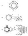
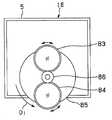
도 2는 상기 제1 실시 형태에 있어서의 LED의 배치예 및 구성예를 도시한 도면.FIG. 2 is a diagram showing an arrangement example and a configuration example of LEDs in the first embodiment. FIG.
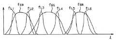
도 3은 상기 제1 실시 형태에 있어서의, CCD의 분광 감도 특성 및 LED의 발광 스펙트럼과, 이들 양자에 의한 분광 특성을 도시한 선도.Fig. 3 is a diagram showing the spectral sensitivity characteristics of the CCD and the emission spectrum of the LED and the spectral characteristics by both of them according to the first embodiment.
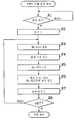
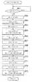
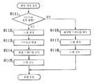
도 4는 상기 제1 실시 형태의 6밴드 분광 화상 취득에 있어서의 각 LED의 발광 및 촬상 소자의 화상 취득의 동작을 도시한 플로우차트.Fig. 4 is a flowchart showing the operation of emitting light of each LED and acquiring an image of an imaging device in six-band spectroscopic image acquisition according to the first embodiment.
도 5는 상기 제1 실시 형태의 6밴드 분광 화상 취득에 있어서의 각 LED의 발광 및 촬상 소자의 화상 취득의 동작 모습을 도시한 타이밍차트.Fig. 5 is a timing chart showing an operation of light emission of each LED and image acquisition of an image pickup device in six-band spectroscopic image acquisition according to the first embodiment.
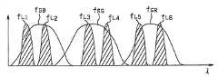
도 6은 상기 제1 실시 형태의 6밴드 분광 화상 취득에 있어서의 각 프레임의 밴드 특성을 도시한 선도.Fig. 6 is a diagram showing band characteristics of each frame in six-band spectroscopic image acquisition according to the first embodiment.
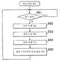
도 7은 상기 제1 실시 형태의 모니터용 화상 취득에 있어서의 각 LED의 발광 및 촬상 소자의 화상 취득의 동작을 도시한 플로우차트.Fig. 7 is a flowchart showing the operation of emitting light of each LED and acquiring an image of an imaging device in acquiring a monitor image according to the first embodiment.
도 8은 상기 제1 실시 형태의 모니터용 화상 취득에 있어서의 각 LED의 발광및 촬상 소자의 화상 취득의 동작 모습을 도시한 타이밍차트.Fig. 8 is a timing chart showing an operation of light emission of each LED and image acquisition of an image pickup device in the monitor image acquisition of the first embodiment.
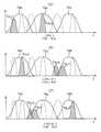
도 9는 상기 제1 실시 형태의 모니터용 화상 취득에 있어서의 각 프레임의 밴드 특성을 도시한 선도.Fig. 9 is a diagram showing the band characteristics of each frame in the monitor image acquisition of the first embodiment.
도 10은 상기 제1 실시 형태에 있어서의, 6원색의 LED가 각각 3개씩 형성되어 있을 때의 점등 실행법의 예를 도시한 도면.Fig. 10 is a diagram showing an example of a lighting execution method when three LEDs of six primary colors are formed in the first embodiment, respectively.
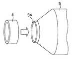
도 11은 상기 제1 실시 형태에 있어서, 하우징의 투사구에 대하여 착탈 가능하게 구성된 패드부를 도시한 사시도.FIG. 11 is a perspective view showing a pad portion detachably configured with respect to the projection port of the housing according to the first embodiment; FIG.
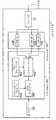
도 12는 상기 제1 실시 형태의 처리 장치에 있어서의 디스플레이에 표시하기 위한 색재현을 행하는 구성을 도시한 블록도.Fig. 12 is a block diagram showing the configuration of color reproduction for display on a display in the processing apparatus of the first embodiment.
도 13은 상기 제1 실시 형태에 있어서, 취득된 피사체 분광 화상에 기초하여 피사체에 관한 화상 판별을 행하기 위한 구성예를 도시한 블록도.Fig. 13 is a block diagram showing a configuration example for performing image discrimination on a subject based on the acquired subject spectroscopic image in the first embodiment.
도 14는 상기 제1 실시 형태의 처리 장치에 있어서 입력 프로파일을 생성하는 구성예를 도시한 블록도.Fig. 14 is a block diagram showing a configuration example of generating an input profile in the processing apparatus of the first embodiment.
도 15는 상기 제1 실시 형태의 촬영 장치의 LCD 모니터에 있어서의 표시예를 도시한 도면.FIG. 15 is a diagram showing a display example of the LCD monitor of the imaging device of the first embodiment; FIG.
도 16은 상기 제1 실시 형태의 화상 처리 시스템을 사용할 때의 모습의 일례를 도시한 도면.Fig. 16 is a diagram showing an example of the state when using the image processing system of the first embodiment.
도 17은 본 발명의 제2 실시 형태에 있어서의 화상 처리 시스템의 구성을 도시한 블록도.Fig. 17 is a block diagram showing the structure of an image processing system according to a second embodiment of the present invention.
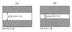
도 18은 상기 제2 실시 형태에 있어서, 풀 모드 및 판독 2배속 모드에 있어서의 판독 모습을 도시한 타이밍차트.Fig. 18 is a timing chart showing the reading mode in the full mode and the read double speed mode in the second embodiment.
도 19는 상기 제2 실시 형태에 있어서, 2/4라인 2배속 모드 및 2/8라인 4배속 모드에 있어서의 판독되는 라인의 모습을 도시한 도면.Fig. 19 is a diagram showing a state of lines to be read in the 2/4 line double speed mode and the 2/8 line quad speed mode in the second embodiment.
도 20은 상기 제2 실시 형태에 있어서, 촬영 모드를 설정할 때의 동작을 도시한 플로우차트.20 is a flowchart showing an operation performed when setting a shooting mode in the second embodiment.
도 21은 본 발명의 제3 실시 형태에 있어서의 화상 처리 시스템의 구성을 도시한 블록도.Fig. 21 is a block diagram showing the structure of an image processing system in a third embodiment of the present invention.
도 22는 상기 제3 실시 형태의 화상 처리 시스템을 사용할 때의 모습의 일례를 도시한 도면.Fig. 22 is a diagram showing an example of the state when using the image processing system of the third embodiment.
도 23은 상기 제3 실시 형태에 있어서의, LED의 발광 스펙트럼 및 컬러 필터 어레이를 통한 CCD의 분광 감도 특성을 도시한 선도.Fig. 23 is a diagram showing the spectral sensitivity characteristics of a CCD through the emission spectrum of the LED and the color filter array in the third embodiment.
도 24는 상기 제3 실시 형태에 있어서, 6밴드의 분광 화상을 생성할 때의 프레임별 분광 화상의 분광 특성을 도시한 선도.Fig. 24 is a diagram showing the spectral characteristics of the spectroscopic images for each frame when generating a six-band spectroscopic image in the third embodiment.
도 25는 상기 제3 실시 형태에 있어서, 모니터용 화상을 생성할 때의 프레임별 분광 화상의 분광 특성을 도시한 선도.FIG. 25 is a diagram showing the spectral characteristics of a spectroscopic image for each frame when generating a monitor image according to the third embodiment; FIG.
도 26은 상기 제3 실시 형태의 6밴드 분광 화상 취득에 있어서의 각 LED의 발광 및 촬상 소자의 화상 취득의 동작을 도시한 플로우차트.Fig. 26 is a flowchart showing the operation of emitting light of each LED and acquiring an image of an image pickup device in six-band spectroscopic image acquisition according to the third embodiment.
도 27은 상기 제3 실시 형태의 6밴드 분광 화상 취득에 있어서의 각 LED의 발광 및 촬상 소자의 화상 취득의 동작 모습을 도시한 타이밍차트.Fig. 27 is a timing chart showing an operation of light emission of each LED and image acquisition of an image pickup device in six-band spectroscopic image acquisition according to the third embodiment.
도 28은 상기 제3 실시 형태의 모니터용 화상 취득에 있어서의 각 LED의 발광 및 촬상 소자의 화상 취득의 동작을 도시한 플로우차트.Fig. 28 is a flowchart showing the operation of emitting light of each LED and acquiring an image of an imaging device in acquiring a monitor image according to the third embodiment;
도 29는 상기 제3 실시 형태의 모니터용 화상 취득에 있어서의 각 LED의 발광 및 촬상 소자의 화상 취득의 동작 모습을 도시한 타이밍차트.Fig. 29 is a timing chart showing an operation of light emission of each LED and image acquisition of the image pickup device in the monitor image acquisition according to the third embodiment.
도 30은 상기 제3 실시 형태에 있어서의, 8밴드의 분광 화상을 생성할 때의 LED의 발광 스펙트럼 및 컬러 필터 어레이를 통한 CCD의 분광 감도 특성을 도시한 선도.Fig. 30 is a diagram showing the spectral sensitivity characteristics of the CCD through the emission spectrum of the LED and the color filter array when generating the eight-band spectroscopic image in the third embodiment.
도 31은 상기 제3 실시 형태에 있어서, 8밴드의 분광 화상을 생성할 때의 프레임별 분광 화상의 분광 특성을 도시한 선도.FIG. 31 is a diagram showing the spectral characteristics of a spectroscopic image for each frame when generating an eight-band spectroscopic image in the third embodiment; FIG.
도 32는 상기 제3 실시 형태의 8밴드 분광 화상 취득에 있어서의 각 LED의 발광 및 촬상 소자의 화상 취득의 동작을 도시한 플로우차트.Fig. 32 is a flowchart showing the operation of emitting light of each LED and acquiring an image of an image pickup device in eight-band spectroscopic image acquisition according to the third embodiment.
도 33은 상기 제3 실시 형태의 8밴드 분광 화상 취득에 있어서의 각 LED의 발광 및 촬상 소자의 화상 취득의 동작 모습을 도시한 타이밍차트.Fig. 33 is a timing chart showing an operation of light emission of each LED and image acquisition of an image pickup device in eight-band spectroscopic image acquisition according to the third embodiment.
도 34는 상기 제3 실시 형태에 있어서, 모니터용 화상을 생성할 때의 프레임별 분광 화상의 분광 특성을 도시한 선도.Fig. 34 is a diagram showing the spectral characteristics of the spectroscopic images for each frame when generating a monitor image in the third embodiment.
도 35는 상기 제3 실시 형태의 모니터용 화상 취득에 있어서의 각 LED의 발광 및 촬상 소자의 화상 취득의 동작을 도시한 플로우차트.Fig. 35 is a flowchart showing the operation of emitting light of each LED and acquiring an image of an imaging device in acquiring a monitor image according to the third embodiment;
도 36은 상기 제3 실시 형태의 모니터용 화상 취득에 있어서의 각 LED의 발광 및 촬상 소자의 화상 취득의 동작 모습을 도시한 타이밍차트.Fig. 36 is a timing chart showing an operation of light emission of each LED and image acquisition of the image pickup device in the monitor image acquisition according to the third embodiment.
도 37은 본 발명의 제4 실시 형태에 있어서의 화상 처리 시스템의 구성을 도시한 블록도.Fig. 37 is a block diagram showing the structure of an image processing system according to a fourth embodiment of the present invention.
도 38은 상기 제4 실시 형태에 있어서, 스펙트럼 검출 센서를 복수개 배열한 화상 처리 시스템을 사용할 때의 모습의 일례를 도시한 도면.Fig. 38 is a diagram showing an example of a state when using an image processing system in which a plurality of spectrum detection sensors are arranged in the fourth embodiment.
도 39는 상기 제4 실시 형태에 있어서의 스펙트럼 검출 센서의 구성예를 도시한 단면도.39 is a cross-sectional view illustrating a configuration example of a spectrum detection sensor in the fourth embodiment.
도 40은 상기 제4 실시 형태의 스펙트럼 검출 센서에 접속되는 광 화이버의 입사단의 모습을 도시한 단면도.40 is a cross-sectional view showing a state of incidence end of an optical fiber connected to the spectrum detection sensor of the fourth embodiment.
도 41은 상기 제4 실시 형태의 스펙트럼 검출 센서에 접속되는 광 화이버의 입사단 근방에 센서용 광학계를 배열한 구성예를 도시한 단면도.Fig. 41 is a sectional view showing a configuration example in which a sensor optical system is arranged in the vicinity of an incidence end of an optical fiber connected to the spectrum detection sensor of the fourth embodiment.
도 42는 상기 제4 실시 형태에 있어서, 환경광 취득용으로 형성된 스펙트럼 검출 센서에 접속되는 광 화이버의 입사단의 모습을 도시한 단면도.FIG. 42 is a cross-sectional view showing an incidence end of an optical fiber connected to a spectrum detection sensor formed for environmental light acquisition in the fourth embodiment; FIG.
도 43은 본 발명의 제5 실시 형태의 치과용 화상 처리 시스템의 시스템 구성도.Fig. 43 is a system configuration diagram of the dental image processing system of the fifth embodiment of the present invention.
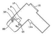
도 44는 상기 도 43의 치과용 화상 처리 시스템에 적용되는 촬영 장치의 블록 구성도.FIG. 44 is a block diagram of a photographing apparatus applied to the dental image processing system of FIG. 43; FIG.
도 45는 본 발명의 제6 실시 형태의 화상 처리 시스템의 구성을 도시한 도면.45 is a diagram showing the configuration of an image processing system according to a sixth embodiment of the present invention.
도 46은 상기 도 45의 화상 처리 시스템의 블록 구성도.FIG. 46 is a block diagram of the image processing system of FIG. 45; FIG.
도 47은 상기 도 45의 화상 처리 시스템의 촬영 장치에 있어서의 촬영 처리 중의 촬영 대기 처리 루틴의 플로우차트.Fig. 47 is a flowchart of a shooting standby processing routine during shooting processing in the shooting device of the image processing system of Fig. 45;
도 48은 상기 도 45의 화상 처리 시스템의 촬영 장치에 있어서의 촬영 처리 중의 촬영 루틴의 플로우차트.FIG. 48 is a flowchart of an imaging routine during an imaging process in the imaging apparatus of the image processing system of FIG. 45. FIG.
도 49는 본 발명의 제7 실시 형태의 화상 처리 시스템의 블록 구성도.Fig. 49 is a block diagram of an image processing system according to a seventh embodiment of the present invention.
도 50은 상기 도 49의 화상 처리 시스템의 촬영 장치에 의해 정반사 피사체를 각 색의 LED 광으로 조명했을 때의 상태를 도시한 도면으로, 도 50의 (A)는 상기 결상시의 정반사되는 피사체와 각 색의 LED와 CCD의 배치를 도시하고, 도 50의 (B)는 정반사 부분의 어느 화상을 도시한 도면.FIG. 50 is a diagram illustrating a state when the specularly reflecting subject is illuminated with LED light of each color by the photographing apparatus of the image processing system of FIG. 49, and FIG. 50A shows the subject that is specularly reflecting at the time of imaging; Fig. 50 is a diagram showing the arrangement of LEDs and CCDs of respective colors, and Fig. 50B shows any image of the specular reflection portion.
도 51은 상기 도 49의 화상 처리 시스템의 촬영 장치에 의해 정반사 피사체를 각 색의 LED 광으로 조명했을 때의 CCD에 결상되는 각 색의 LED의 조명에 의한 정반사 부분이 존재하는 피사체상과, 상기 화상 처리 시스템의 촬영 장치에서 상기 피사체상으로부터 정반사 부분을 삭제한 피사체상을 도시한 도면.Fig. 51 is a subject image in which a specular reflection portion by illumination of LEDs of respective colors is formed by the imaging device of the image processing system of Fig. 49 when the specular reflection object is illuminated with LED lights of respective colors; A subject image in which the specular reflection portion is deleted from the subject image in the photographing apparatus of the image processing system.
도 52는 상기 도 49의 화상 처리 시스템의 촬영 장치에 있어서의 정반사 부분 삭제 처리의 플로우차트.Fig. 52 is a flowchart of the specular reflection partial deletion processing in the photographing apparatus of the image processing system of Fig. 49;
도 53은 본 발명의 제8 실시 형태의 화상 처리 시스템의 블록 구성도.Fig. 53 is a block diagram of an image processing system according to an eighth embodiment of the present invention.
도 54는 상기 도 53의 화상 처리 시스템의 촬영 장치에 의해, 정반사 피사체를 촬영한 경우에 있어서의 상기 정반사 피사체상에서의 광의 반사 상태를 도시한 도면.Fig. 54 is a diagram showing a state of reflection of light on the specular subject when the specular subject is photographed by the photographing apparatus of the image processing system of Fig. 53;
도 55는 본 발명의 제9 실시 형태의 화상 처리 시스템의 블록 구성도.Fig. 55 is a block diagram of an image processing system according to a ninth embodiment of the present invention.
도 56은 상기 도 55의 화상 처리 시스템의 촬영 장치에 있어서의 CCD의 전면에 배치되는 제2 편광판의 정면도.FIG. 56 is a front view of a second polarizing plate disposed in front of a CCD in the imaging device of the image processing system of FIG. 55; FIG.
도 57은 본 발명의 제10 실시 형태의 화상 처리 시스템의 블록 구성도.Fig. 57 is a block diagram of an image processing system according to a tenth embodiment of the present invention.
도 58은 상기 도 57의 화상 처리 시스템의 촬영 장치에 있어서의 LED 광원에 의한 쉐이딩 상태의 보정전을 도시한 도면으로, 도 58의 (A) 및 도 58의 (B)는 각각 다른 LED의 쉐이딩 상태를 도시한 도면.Fig. 58 is a diagram showing the correction before the shading state by the LED light source in the image capturing apparatus of the image processing system of Fig. 57, wherein Figs. 58A and 58B each show the shading of different LEDs. Figure showing the state.
도 59는 상기 도 57의 화상 처리 시스템의 촬영 장치에 있어서의 LED 광원에 의한 쉐이딩 상태의 보정후를 도시한 도면으로, 도 59의 (A) 및 도 59의 (B)는 각각 다른 LED의 쉐이딩 보정 상태를 도시한 도면.Fig. 59 is a view showing the correction of the shading state by the LED light source in the image capturing apparatus of the image processing system of Fig. 57, and Figs. 59A and 59B are each shaded different LEDs. Figure showing the correction state.
도 60은 본 발명의 제11 실시 형태의 화상 처리 시스템의 블록 구성도.60 is a block diagram of an image processing system according to an eleventh embodiment of the present invention.
도 61은 상기 도 60의 화상 처리 시스템에 있어서의 촬영 장치의 LED 광원부의 배치도.Fig. 61 is a layout view of an LED light source unit of the imaging device in the image processing system of Fig. 60.
도 62는 본 발명의 제12 실시 형태인 화상 처리 시스템의 블록 구성도.Fig. 62 is a block diagram showing an image processing system according to a twelfth embodiment of the present invention.
도 63은 본 발명의 제13 실시 형태인 화상 처리 시스템의 블록 구성도.Fig. 63 is a block diagram showing an image processing system according to a thirteenth embodiment of the present invention.
도 64는 본 발명의 제14 실시 형태인 화상 처리 시스템의 블록 구성도.64 is a block diagram of an image processing system according to a fourteenth embodiment of the present invention;
도 65는 본 발명의 제15 실시 형태인 화상 처리 시스템의 시스템 구성도.65 is a system configuration diagram of an image processing system according to a fifteenth embodiment of the present invention.
도 66은 본 발명의 제16 실시 형태인 화상 처리 시스템에 적용되는 화상 촬영부의 블록 구성도.Fig. 66 is a block diagram of an image photographing unit applied to an image processing system according to a sixteenth embodiment of the present invention.
도 67은 본 발명의 제17 실시 형태인 화상 처리 시스템에 적용되는 촬영 장치의 블록 구성도.Fig. 67 is a block diagram of a photographing apparatus applied to an image processing system according to a seventeenth embodiment of the present invention.
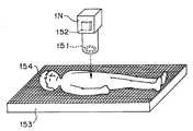
도 68은 본 발명의 제18 실시 형태인 화상 처리 시스템에 의한 진찰 상태를 도시한 도면.Fig. 68 is a diagram showing a diagnosis state by the image processing system according to the eighteenth embodiment of the present invention.
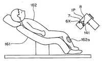
도 69는 본 발명의 제19 실시 형태인 화상 처리 시스템에 의한 진찰 상태를 도시한 도면.Fig. 69 is a diagram showing a medical examination state by the image processing system according to the nineteenth embodiment of the present invention.
본 발명은 피사체의 분광 스펙트럼 화상 정보를 취득하고, 취득 화상으로부터 피사체의 화상의 고정밀도의 색재현이나 검사, 판정 등을 행하는 화상 처리 시스템에 관한 것이다.BACKGROUND OF THE
최근, 건강에 대한 관심이 높아지고 있으며, 또한 심미 추구로서 화이트닝에의 요구가 높아지고 있다. 종래, 피부과, 에스테틱 살롱, 미용 카운셀링 등에서는, 피부 진단용 카메라가 이용되어 진단에 사용되어 왔다. 특히 피부과의 경우에는, 피부 표면의 진단으로서, 피부 구멍이나 피부 돌출 부분의 화상으로부터 특징을 포착하여 카운셀링이 행해지고 있다. 또한, 상기 피부 진단용 카메라에 관해서는, 일본 특허공개평8-149352호 공보나, 특허공개평7-322103호 공보 등에 제안이 되어 있다.In recent years, interest in health has increased, and the demand for whitening has increased as aesthetic pursuit. Background Art Conventionally, in dermatology, aesthetic salons, beauty counseling, etc., a skin diagnostic camera has been used for diagnosis. In particular, in the case of dermatology, counseling is performed by capturing features from images of skin pores and skin protrusions as a diagnosis of the skin surface. Further, the skin diagnosis camera has been proposed in Japanese Patent Laid-Open No. 8-149352, Japanese Patent Laid-Open No. 7-322103, and the like.
한편, 치과 치료에 있어서의 의치 제작에 관해서는, 종래에는 의치의 색을 결정할 때, 쉐이드 가이드에 의해 환자 본인의 치아의 색과 비교함으로써 색의 등급 판정이 행해지고 있다.On the other hand, regarding the production of dentures in dental treatment, when determining the color of dentures, color grading is performed by comparing with the color of the teeth of the patient's own person by the shade guide.
상술한 바와 같이 피부과, 치과를 비롯하여 정확한 색재현이 요구되고 있지만, 종래의 고정밀도의 색재현 시스템으로서 일본 특허공개 2000-152269호 공보에 개시된 시스템은 외부 조명하의 피사체를 멀티 스펙트럼하에서 촬영하는 카메라를 적용하는 것이다. 이 시스템에서는, 피사체 분광 스펙트럼의 고정밀도의 추정을 위하여 다수의 회전 가능한 분광 필터를 이용하고, 그 회전에 의하여 많은 밴드의 데이터를 취득하여, 높은 색재현을 실현 가능하게 하는 것이다.As described above, accurate color reproduction, including dermatology and dentistry, is required, but the system disclosed in Japanese Patent Laid-Open No. 2000-152269 as a conventional high-precision color reproduction system uses a camera that photographs a subject under external illumination under multi-spectrum. To apply. In this system, a large number of rotatable spectral filters are used for high accuracy estimation of the subject spectral spectrum, and data of a large number of bands is obtained by the rotation, thereby enabling high color reproduction.
상술한 피부과, 치과, 또한 정확한 색재현을 요구하는 다른 분야로서, 예를 들면 자동차의 도장색, 건물의 도장색, 식료품의 분광 특성, 의료품의 염색 등에서는 색을 충실하게 색재현하여, 진단, 검사, 확인이나 판별에 사용하는 것이 요구되고 있다. 또한, 이들 장치에 대해서는, 검사 작업성을 고려하여 소형 경량, 또한 핸디인 것도 요구되고 있다.As the dermatology, dentistry, and other fields that require accurate color reproduction, for example, paint color of automobiles, paint color of buildings, spectral characteristics of foodstuffs, dyeing of medical products, etc., faithfully reproduce the color, and diagnose, examine, It is required to use for confirmation and discrimination. In addition, these apparatuses are also required to be small, light and handy in consideration of inspection workability.
그러나, 상술한 상기 일본 특허공개평8-149352호 공보나 특허공개평7-322103호 공보 등의 피부 진단용 카메라의 예는 핸디인 것이기는 하지만, 재현성, 높은 색재현에 대하여 충분한 것이라고는 할 수 없다. 또한, 상기 일본 특허공개 2000-152269호 공보에 개시된 회전 필터형을 적용하는 높은 색재현 시스템은 고정 배치형으로 중량이 무겁고, 또한 외부 조명 때문에, 색재현 처리를 위해서는 별도의 조명 센서가 필요하였다.However, the above-described examples of skin diagnostic cameras such as Japanese Patent Application Laid-open No. Hei 8-149352 and Japanese Patent Laid-Open No. Hei 7-322103 are handy, but are not sufficient for reproducibility and high color reproduction. . In addition, the high color reproduction system applying the rotary filter type disclosed in Japanese Patent Application Laid-Open No. 2000-152269 has a fixed arrangement type, is heavy in weight, and because of external illumination, a separate illumination sensor is required for color reproduction processing.
또한, 종래의 치과 치료에 있어서, 치아의 색을 선택하는 경우, 상술한 바와 같이 색의 농담을 나타내는 쉐이드 가이드로 비교 판단되고 있었지만, 주관적이고, 또한 실내광의 열화, 변화에 의해서도 영향을 받아, 오차가 생기고 있었다. 또한, 기록을 사진으로 행하고 있었지만, 카메라 설정의 확인이 필요하거나, 화상의 크기도 맞추기 어렵고, 또한 필름 감도나 현상 감도가 일정하지 않는 등 정확성이 부족하였다.In the conventional dental treatment, when the color of the tooth is selected, it was judged as a shade guide showing the color shade as described above. However, it is subjective and affected by the deterioration and change of the room light. Was happening. In addition, although recording was performed with a photograph, accuracy was lacking, such as confirmation of camera settings, difficulty in matching the size of the image, and inconsistent film sensitivity and developing sensitivity.
그 밖에, 종래의 소형 촬영 장치를 적용하는 색재현 화상 시스템에 있어서의 문제점으로서,In addition, as a problem in a color reproduction image system to which a conventional compact photographing apparatus is applied,
(1) 간단한 구성의 휴대 가능한 촬영 장치에 의해 환경광에 좌우되지 않는 상태에서 더욱 정확한 분광 화상 데이터를 취득할 수 있도록 한 것의 제안은 아직 이루어져 있지 않다.(1) Proposal for obtaining more accurate spectroscopic image data without being influenced by ambient light by a portable imaging device having a simple configuration has not been made yet.
(2) 피사체가 정반사되는 듯한 광택이 있는 피사체인 경우, 취입된 화상 데이터에 광원에 의한 고정밀도 부분이 생길 가능성이 있지만, 이 점을 간단한 장치로 해결하는 것의 제안도 아직 이루어져 있지 않다.(2) In the case of a subject having a gloss that seems to be specularly reflected, there is a possibility that a high-precision part due to a light source is formed in the captured image data, but proposals for solving this point with a simple device have not been made yet.
(3) 색재현을 고정밀도로 하기 위하여, 기준색을 배색한 색표에 의한 캘리브레이션 처리가 행해지고 있지만, 상기 색표는 촬영 장치와는 별도로 준비되기 때문에, 보관 관리가 필요해진다. 이 보관 관리는 사람 손으로 다루어지기 때문에, 색표에 오물이 부착되기 쉽고, 또한 관리 방법에 따라서는 외광에 노출되어 열화될 가능성이 있었다,(3) In order to make color reproduction highly accurate, the calibration process by the color table which color-coded the reference color is performed, but since the said color table is prepared separately from a photographing apparatus, storage management is needed. Since this storage management is handled by human hands, it is easy for dirt to adhere to the color table, and depending on the management method, it may be exposed to external light and degrade.
(4) 피사체를 조명하는 광원의 배치에 의하여 쉐이딩이 발생할 가능성이 있지만, 상기 쉐이딩을 간단한 장치로 방지할 필요가 있다.(4) Although shading may occur due to the arrangement of the light source illuminating the subject, it is necessary to prevent the shading with a simple device.
(5) 인체의 혈류 상태나, 체온, 맥박, 심박 등의 관리에 대하여 색재현 화상 시스템을 적용하면, 정확한 진단을 용이하게 행하는 것이 가능해지지만 이들의 제안이 이루어져 있지 않다.(5) When the color reproduction imaging system is applied to the management of blood flow, body temperature, pulse rate, heart rate, etc. of the human body, accurate diagnosis can be easily performed, but these proposals are not made.
(6) 인체 환부의 촬영시에 있어서 그 촬영 위치의 특정, 또는 촬영 피사체상의 크기 등의 관리를 용이하게 행하는 것이 가능한 시스템이 아직 제안되어 있지 않다.(6) At the time of imaging of the human affected part, there has not yet been proposed a system capable of easily specifying the photographing position or managing the size of the photographed subject.
본 발명은 상기 사정을 감안하여 이루어진 것으로, 고정밀도의 색재현이나 검사, 판정이 가능하고, 정보 통신 처리에 대해서도 바람직하고, 또한 그 촬상부가 소형 경량이고 휴대성이 우수한 화상 처리 시스템을 제공하는 것을 목적으로 하고 있다.SUMMARY OF THE INVENTION The present invention has been made in view of the above circumstances, and it is possible to provide high-resolution color reproduction, inspection, and determination, and is also preferable for information communication processing, and the imaging unit provides a small size, light weight, and excellent portability. It is aimed.
제1 발명은 피사체를 촬영하기 위한 촬상 광학계와, 상기 피사체로부터의 피사체 신호를 취득하기 위한 촬상 소자부와, 각각 서로 다른 분광 분포 특성을 갖는 복수의 조명 광원과, 화상 촬영 조작을 행하기 위한 촬영 조작부를 가지며, 상기 복수의 조명 광원을 상기 촬상 소자부의 노광 타이밍과 연동하고, 또한 상기 복수의 조명 광원을 선택적으로 점등시킴으로써 복수의 피사체 분광 화상을 얻는 화상 촬영부와, 상기 화상 촬상부에서 촬영된 상기 피사체 분광 화상을 기억하기 위한 화상 메모리부를 가지며, 상기 화상 메모리부에 기억된 화상 신호로부터 원하는 화상 연산을 행하는 화상 처리부를 갖고 있는 화상 처리 시스템이다.The first invention provides an imaging optical system for photographing a subject, an imaging element unit for acquiring a subject signal from the subject, a plurality of illumination light sources each having different spectral distribution characteristics, and photographing for performing an image photographing operation. An image capturing unit having an operation unit and obtaining a plurality of subject spectroscopic images by linking the plurality of illumination light sources with the exposure timing of the imaging element unit and selectively lighting the plurality of illumination light sources; An image processing system having an image memory section for storing the subject spectroscopic image, and having an image processing section for performing a desired image operation from the image signal stored in the image memory section.
또한, 제2 발명은 상기 제1 발명에 있어서, 상기 화상 처리부가, 또한 상기 화상 메모리부에 기억된 화상 신호로부터 피사체의 소정의 등급 연산, 판별 또는 해석을 행하는 것을 특징으로 한다.The second invention is characterized in that in the first invention, the image processing unit performs predetermined grade calculation, determination or analysis of the subject from the image signal stored in the image memory unit.
또한, 제3 발명은 상기 제1 발명에 있어서, 상기 화상 촬영부가, 또한 환경광의 분광 분포 특성을 검출하기 위한 조명 검출 센서를 구비하고 있으며, 외부 스트로보 발광 장치가 착탈 가능하고, 상기 조명 검출 센서의 검출부는 상기 외부 스트로보 발광 장치가 장착되었을 때에 스트로보 광의 도광로와 광학적으로 결합하는 것을 특징으로 한다.Further, in the first invention, in the first invention, the image photographing unit further includes an illumination detection sensor for detecting a spectral distribution characteristic of ambient light, and an external strobe light emitting device is detachable. The detector is optically coupled to the light guide path of the strobe light when the external strobe light emitting device is mounted.
제4 발명은 상기 제1 발명에 있어서, 상기 화상 촬영부가, 상기 조명 광원이 피사체에 직접 비춰드는 것을 방지하기 위한 반사광 제거 수단을 더 구비하는 것을 특징으로 한다.According to a fourth aspect of the present invention, the image photographing unit further includes reflection light removing means for preventing the illumination light source from directly shining on a subject.
제5 발명은 상기 제1 발명에 있어서, 상기 화상 촬영부가, 상기 조명 광원과 피사체 사이에 조명 얼룩을 경감하기 위한 광학 부재를 더 구비하는 것을 특징으로 한다.According to a fifth aspect of the invention, in the first aspect of the invention, the image photographing unit further includes an optical member for reducing an illumination spot between the illumination light source and the subject.
제6 발명은 상기 제1 발명에 있어서, 상기 화상 촬영부가, 외부 조명 장치와 연동하기 위한 접속 접점부를 가지며, 상기 접속 접점부를 통해 접속된 외부 조명 장치는 상기 조명 광원과 대략 동일한 점등 순서로 점등하는 것을 특징으로 한다.According to a sixth aspect of the present invention, in the first aspect, the image photographing portion has a connection contact portion for interlocking with an external lighting device, and the external lighting device connected through the connection contact portion lights in the same lighting sequence as the illumination light source. It is characterized by.
제7 발명은 상기 제1 발명에 있어서, 상기 복수의 조명 광원이, 중심 파장이 780㎚ 내지 900㎚인 광원, 또는 중심 파장이 300㎚ 내지 380㎚인 광원을 적어도 1개 포함하는 것을 특징으로 한다.According to a first aspect of the present invention, the plurality of illumination light sources include at least one light source having a center wavelength of 780 nm to 900 nm or a light source having a center wavelength of 300 nm to 380 nm. .
제8 발명은 상기 제1 발명에 있어서, 상기 화상 촬영부와 화상 처리부가 일체화되어 형성되어 있는 것을 특징으로 한다.In the eighth invention, in the first invention, the image capturing unit and the image processing unit are integrally formed.
제9 발명은 상기 제1 발명에 있어서, 상기 화상 촬영부가, 상기 화상 처리부에 있어서의 캘리브레이션을 행하기 위한 색표를 내장하는 것을 특징으로 한다.According to a ninth aspect of the invention, in the first aspect, the image photographing section includes a color table for performing calibration in the image processing section.
제10 발명은 상기 제1 발명에 있어서, 상기 화상 촬영부로서, 촬영 기능을 갖는 휴대 단말 장치를 적용하고, 각각 서로 다른 분광 분포 특성을 갖는 복수의 조명 광원이 유닛화된 조명 광원부가 상기 촬영 기능을 갖는 휴대 단말 장치에 장 착 가능한 것을 특징으로 한다.In the tenth invention, in the first invention, an illumination light source unit in which a portable terminal device having a photographing function is applied as the image photographing unit, and a plurality of illumination light sources each having different spectral distribution characteristics are unitized. Characterized in that it can be mounted on a portable terminal device having a.
제11 발명은 상기 제1 발명에 있어서, 화상 처리부에 화상 파일링 소프트웨어가 구비되어 있으며, 상기 촬영 조작부가 조작되었을 때에 촬영된 화상 데이터가 상기 화상 파일링 소프트웨어의 소정의 개소에 기록되는 것을 특징으로 한다.In the eleventh aspect of the present invention, in the first invention, image filing software is provided in the image processing unit, and image data shot when the photographing operation unit is operated is recorded in a predetermined location of the image filing software.
제12 발명은 상기 제1 발명에 있어서, 상기 화상 촬영부가 상기 피사체의 부위 정보를 취득하기 위한 피사체 부위 검출 수단을 더 갖는 것을 특징으로 한다.In a twelfth aspect of the present invention, the image photographing section further includes subject portion detecting means for acquiring region information of the subject.
제13 발명은 상기 제1 발명에 있어서, 상기 화상 촬영부가 온도 측정부를 더 갖는 것을 특징으로 한다.According to a thirteenth invention, in the first invention, the image photographing unit further has a temperature measuring unit.
제14 발명은 상기 제1 발명에 있어서, 상기 화상 촬영부가 맥박 측정부를 더 갖는 것을 특징으로 한다.According to a fourteenth aspect of the invention, in the first aspect of the invention, the image photographing unit further has a pulse measuring unit.
제15 발명은 상기 제1 발명에 있어서, 상기 화상 촬영부가 청진 기능을 더 갖는 것을 특징으로 한다.In a fifteenth aspect of the present invention, the image photographing unit further has a stethoscope function.
제16 발명은 상기 제1 발명에 있어서, 상기 화상 촬영부가 측거(測距) 수단을 더 갖고 있으며, 촬영된 화상중의 피사체의 크기를 관리하는 것을 특징으로 한다.In a sixteenth aspect of the invention, in the first aspect of the invention, the image photographing section further includes a range measuring means, and the size of the subject in the photographed image is managed.
이하, 도면을 참조하여 본 발명의 실시 형태를 설명한다.EMBODIMENT OF THE INVENTION Hereinafter, embodiment of this invention is described with reference to drawings.
도 1 내지 도 16은 본 발명의 제1 실시 형태를 도시한 것으로, 도 1은 화상 처리 시스템의 구성을 도시한 블록도이다.1-16 show the 1st Embodiment of this invention, and FIG. 1 is a block diagram which shows the structure of an image processing system.
이 화상 처리 시스템은 가시광역에 있어서 서로 독립적이며 서로 다른 복수 의 파장 대역의 조명광에 의해 피사체를 조명하여 피사체 분광 화상을 촬영할 수 있는 촬영 장치(1)와, 이 촬영 장치(1)와 접속되어 있으며 이 촬영 장치(1)로부터 출력되는 피사체 분광 화상을 처리하는 처리 장치(2)를 갖고 구성되어 있으며, 이 처리 장치(2)는 필요에 따라서 네트워크(3)에 접속할 수 있도록 구성되어 있다.The image processing system is connected to the photographing
상기 촬영 장치(1)는 본 실시 형태에 있어서는, 6종류의 파장 대역의 조명광(6원색의 조명광)을 피사체에 순차 조사하여, 6장의 피사체 분광 화상을 정지 화상으로서 취득하는 촬상과, 6원색의 조명광으로부터 1이상의 조명광을 각각 선택하여 RGB의 3색의 조명광으로 하여 이들을 순차 조사함으로써 면순차식(面順次式)의 동화상으로서 취득하는 촬상을 행할 수 있도록 되어 있다.In the present embodiment, in the present embodiment, imaging is performed by sequentially irradiating six kinds of illumination light (six illumination colors) of six wavelength bands to a subject to acquire six subject spectroscopic images as a still image, and six primary colors. At least one illumination light is selected from the illumination light, and the illumination light of three colors of RGB is irradiated, and these are sequentially irradiated, so that imaging acquired as a surface-sequential moving image can be performed.
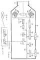
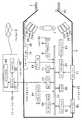
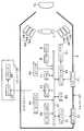
상기 촬영 장치(1)는 후술하는 조명광을 피사체에 투사함과 아울러 피사체로부터의 반사광을 입사하기 위한 투사구(5a)를 구비한 하우징(5)과, 이 하우징(5)의 투사구(5a)측에 착탈 가능하게 장착되어 있으며 이 투사구(5a)를 통해 피사체에 투사하는 조명광에 외광이 혼입되지 않도록 차광하기 위한 유연성을 갖는 소재에 의해 대략 통형상으로 형성된 패드부(4)와, 상기 하우징(5)내에 병합되어 있으며 점등됨으로써 피사체를 조명하기 위한 조명광을 발광하는 발광 소자인 제1 LED(6a)∼제6 LED(6f)와, 상기 하우징(5)내에 병합되어 있으며 이들 제1 LED(6a)∼제6 LED(6f)에 의해 조명된 피사체상을 결상하기 위한 촬상 광학계(7)와, 이 촬상 광학계(7)에 의해 결상된 피사체상을 촬상하여 화상 신호를 출력하는 촬상 소자부에 포함되는 촬상 소자인 CCD(8)와, 이 CCD(8)로부터 출력되는 아날로그 신호를 디지털 신호로 변환하는 A/D 변환기(9)와, 이 A/D 변환기(9)로부터 출력되고 후술하는 버 스(10)를 통해 전송되는 피사체 분광 화상을 일단 기억함과 아울러 후술하는 CPU(18)에 의한 작업 영역으로서도 이용되는 메모리(11)와, 사용자가 분광 화상 촬영 동작의 개시를 지시 입력하거나 동화상 촬영 동작의 개시나 종료를 지시 입력하기 위한 각종 조작 스위치나 조작 버튼을 포함하여 이루어지는 촬영 조작부인 조작 스위치(14)와, 이 조작 스위치(14)로부터의 지시 입력을 후술하는 CPU(18)에 전달함과 아울러 이 CPU(18)로부터의 지령에 의해 상기 제1 LED(6a)∼제6 LED(6f)의 발광 제어에 관한 명령 등을 행하거나 이 촬영 장치(1)의 촬상 동작에 관한 제어를 행하는 카메라 제어 I/F(12)와, 이 카메라 제어 I/F(12)로부터의 지령에 기초하여 상기 제1 LED(6a)∼제6 LED(6f)의 발광 개시 타이밍이나 발광 종료 타이밍 등의 발광 동작에 따른 제어를 행하는 LED 드라이버(13)와, 상기 CCD(8)에 의해 촬상되는 동화상이나 상기 메모리(11)에 기억된 피사체 분광 화상(정지 화상)을 후술하는 LCD 모니터(16)에 표시하기 위한 제어를 행하는 모니터 I/F(15)와, 이 모니터 I/F(15)로부터 출력되는 화상을 표시하기 위한 LCD 모니터(16)와, 상기 메모리(11)에 기억된 피사체 분광 화상이나 후술하는 CPU(18)로부터의 제어 데이터 등을 상기 처리 장치(2)에 출력하거나 또는 이 처리 장치(2)로부터의 통신 데이터를 입력하기 위한 외부 I/F(17)와, 상기 A/D 변환기(9), 메모리(11), 카메라 제어 I/F(12), 모니터 I/F(15), 외부 I/F(17), 후술하는 CPU(18) 등을 서로 접속하는 버스(10)와, 상술한 각 회로를 포함하는 이 촬영 장치(1)를 총괄적으로 제어하는 제어부인 CPU(18)를 갖고 구성되어 있다.The photographing
상기 처리 장치(2)는 예를 들면 퍼스널 컴퓨터 등으로 이루어지고, 상기 외 부 I/F(17)로부터 출력되는 피사체 분광 화상을 수신하여, 후술하는 바와 같이 입력 프로파일을 이용하여 X, Y, Z 삼자극값을 산출하고, 또한 이 XYZ 삼자극값으로부터 디스플레이 프로파일을 이용하여 피사체가 부여한다고 추정되는 XYZ 삼자극값과 거의 동일한 XYZ 삼자극값이 후술하는 디스플레이(22)에 의해 얻어지는 표시용 신호를 생성하는 연산 장치(21)와, 이 연산 장치(21)로부터 출력되는 표시용 신호에 의해 고도의 색재현이 이루어진 화상을 표시하는 디스플레이(22)를 가지며, 또한, 특히 도시는 하지 않지만 상기 네트워크(3)에 접속하기 위한 네트워크 인터페이스 등도 구비하여 구성되어 있다.The
또한, 상기 촬영 장치(1)와 처리 장치(2)는 유선에 의해 접속되어 있어도 되고, 예를 들면 Bluetooth나 무선 LAN 등의 무선에 의해 접속되어 있어도 무방하고, 또는 일체로 구성되어 있어도 된다.The
도 3은 CCD(8)의 분광 감도 특성 및 LED(6a∼6f)의 발광 스펙트럼과, 이들 양자에 의한 분광 특성을 도시한 선도이다.3 is a diagram showing the spectral sensitivity characteristics of the
발광 소자인 상기 제1 LED(6a)∼제6 LED(6f)는 도 3의 (A)에 도시한 바와 같이, 각각 서로 다른 독립된 발광 스펙트럼을 갖는 것으로 되어 있으며, 곡선 fL1에 의해 표시되는 제1 LED(6a)의 광은 예를 들면 약간 자색을 띤 청색, 곡선 fL2에 의해 표시되는 제2 LED(6b)의 광은 예를 들면 약간 녹색을 띤 청색, 곡선 fL3에 의해 표시되는 제3 LED(6c)의 광은 예를 들면 약간 청색을 띤 녹색, 곡선 fL4에 의해 표시되는 제4 LED(6d)의 광은 예를 들면 약간 황색을 띤 녹색, 곡선 fL5에 의해 표시되는 제5 LED(6e)의 광은 예를 들면 오렌지, 곡선 fL6에 의해 표시되는 제6 LED(6f)의 광은 예를 들면 적색 등으로 되어 있다.As shown in Fig. 3A, the
또한, 도시한 예에서는, 제1 LED(6a)∼제6 LED(6f)의 각 발광 스펙트럼은 서로 겹쳐지지 않게 완전히 분리되어 있지만, 일부가 겹쳐지는 발광 스펙트럼이어도 무방하다. 물론 LED의 종류도 6종류에 한정되는 것은 아니고, 적절한 종류수의 LED의 조합을 채용할 수 있다.In the illustrated example, the light emission spectra of the
여기에, 각 LED에 의한 조명광의 스펙트럼 배열은 균등 파장 간격(파장 방향으로 균등한 간격으로 예를 들면 피크가 늘어선 것), 균등 파장비 간격(파장 방향으로 일정한 비율 간격으로 피크 등이 늘어선 것), 특정 목적용의 특정 배열(특정 목적에 따라 파장 방향으로 특정 배열로 피크 등이 늘어선 것), 특정 파장색 체배 설정(특정 파장을 기본 파장으로 하여 체배 파장 위치에 피크 등이 늘어선 것), 특정 편광색 배치(파장 방향을 따라 늘어선 피크로 표시되는 각 광이 특정 방향으로 편광되어 있는 것), 가시역외 광 배치(파장 방향을 따라 늘어선 피크로 표시되는 광이 가시역외의 영역에도 도달해 있는 것) 등의 어느것이더라도 채용하는 것이 가능하고, 사용 목적에 가장 합치하는 것을 선택하도록 하면 된다.Here, the spectral arrangement of the illumination light by each LED includes equal wavelength intervals (for example, the peaks are lined up at equal intervals in the wavelength direction), and equal wavelength ratio intervals (the peaks are lined up at constant ratio intervals in the wavelength direction). , Specific arrays for specific purposes (peaks are arranged in a specific array in the wavelength direction according to specific purposes), specific wavelength color multiplication settings (peaks are arranged at multiplication wavelengths with specific wavelengths as the base wavelength), and Polarization color arrangement (each light represented by peaks along the wavelength direction polarized in a particular direction), out-of-visible light arrangement (light represented by peaks along the wavelength direction reaching the region outside the visible range It is possible to employ any of the above, and it is good to select the one that best matches the purpose of use.
또한, 여기서는, 발광 소자로서, 경량, 소형, 아울러 비교적 저가로 입수 용이하면서 고휘도의 반도체 발광 소자인 LED를 이용하고 있지만, 이것에 한정되지 않고, 예를 들면 LD(레이저 다이오드) 등의 반도체 레이저나 그 밖의 발광 소자를 이용하는 것도 가능하다.In addition, although the light emitting element uses LED which is light weight, small size, and is easy to obtain at a comparatively low cost, and is a high brightness | luminance semiconductor light emitting element, it is not limited to this, For example, semiconductor lasers, such as LD (laser diode), It is also possible to use other light emitting elements.
한편, 상기 CCD(8)는 본 실시 형태에 있어서는, 모노크롬 타입의 CCD를 사용하고 있으며, 그 센서 감도는 도 3의 (A)의 곡선 fs로 나타낸 바와 같이 가시광역 을 거의 커버하는 것으로 되어 있다. 또한, 여기서는 촬상 소자로서 모노크롬 타입의 CCD를 이용하고 있지만, 이것에 한정되는 것은 아니고, 후술하는 실시 형태에 있어서 언급하는 바와 같이 컬러 타입의 CCD를 이용해도 되고, CCD에 한정되지 않고 CMOS 타입이나 그 밖의 각종 촬상 소자를 널리 사용하는 것이 가능하다.On the other hand, the
그리고, 상기 제1 LED(6a)∼제6 LED(6f)에 의해 조명된 피사체의 상을 이 CCD(8)에 의해 수광할 때의 분광 감도 특성은 예를 들면 도 3의 (B)에 나타낸 곡선 fSL1∼fSL6과 같이 되어 있다. 이와 같은 전체적인 분광 감도 특성의 파장에 의한 상이는 후단에서 전기적으로 처리되거나, 또는 촬영 장치(1)에 따른 입력 프로파일 등으로서 보정되게 된다.And the spectral sensitivity characteristic at the time of receiving the image of the subject illuminated by the said
또한, 도 2는 LED의 배치예 및 구성예를 도시한 도면이다.2 is a diagram showing an arrangement example and a configuration example of the LED.
도 2의 (A)는 6종류의 원색으로 구성되는 상기 제1 LED(6a)∼제6 LED(6f)를, 링 형상으로 순차로 3세트(각 색 3개씩) 배치한 예를 도시하고 있다. 또한, 도시한 배치순은 일례를 나타낸 것뿐이고, 이것에 한정되지 않으며, 역순이나 랜덤 배치 등의 임의의 배열을 널리 적용하는 것이 가능하다.FIG. 2A shows an example in which the
다음으로, 도 2의 (B)는 링 형상으로 발광부(6A)를 복수개 배치하고 있으며, 아울러 각 발광부(6A)내에 6종류의 원색을 포함하도록 상기 제1 LED(6a)∼제6 LED(6f)를 배치한 예를 도시하고 있다. 또한, 도시한 예에서는, 1개의 발광부(6A)내에 6원색 전부를 배치하고 있지만, 이것에 한정되지 않으며, 3원색씩을 배치하는 등의 6원색이 복수의 발광부(6A)에 나뉘어지도록 해도 무방하다.Next, in FIG. 2B, a plurality of light emitting
또한, 도 2의 (C)는 상기 제1 LED(6a)∼제6 LED(6f) 각각에 화이버 번들(6B) 의 일단측(6Ba∼6Bf)을 접속하고, 타단측(6Bg)을 링 형상으로 형성한 것이다. 이에 따라, LED(6a∼6f)로부터 발광된 조명광은 번들 화이버단(6Ba∼6Bf)에 입사된다. 번들 화이버단은 복수의 더욱 가느다란 화이버로 구성되어 있으며, 번들 화이버의 사출부(6Bg)에서는 각 LED로부터의 이들 가느다란 화이버는 서로 혼합되어 링 형상의 균일한 광원으로서 피사체에 조사되어, 피사체에 의한 전반사의 영향을 저감할 수 있다.2C is connected to each of the
또한, LED의 배치는 도 2에 도시한 예에 한정되지 않고, CCD(8)에 의한 촬상에 지장을 초래하지 않는 한, 링 형상 배치, 십자형상 배치, 직사각형 배치, 랜덤 배치 등의 적절한 배치를 채용하는 것이 가능하다.In addition, arrangement | positioning of LED is not limited to the example shown in FIG. 2, As long as it does not interfere with the imaging by CCD8, suitable arrangement | positioning, such as ring-shaped arrangement, cross-shaped arrangement, rectangular arrangement, random arrangement, etc. is carried out. It is possible to adopt.
다음으로, 이 촬영 장치(1)에서는 2종류의 화상 취득 모드가 있는 것에 관하여 설명한다.Next, in this
상술한 바와 같이, 이 촬영 장치(1)는 통상의 RGB 화상으로서의 동화상과, 고도의 색재현을 가능하게 하는 6원색의 피사체 분광 화상으로서의 정지 화상을 촬상할 수 있도록 되어 있으며, 동화상은 모니터용 화상 취득 모드에서, 정지 화상은 분광 화상 취득 모드에서, 각각 촬상되도록 되어 있다.As described above, the photographing
이들 2개의 모드는 상기 조작 스위치(14)에 포함되어 있는 누름식의 버튼 스위치로 이루어지는 촬영 버튼(14a)(도 16 참조)을 누름으로써 전환되도록 구성되어 있다.These two modes are configured to be switched by pressing the photographing button 14a (see Fig. 16) which is constituted by a push button switch included in the
즉 먼저, 전원 스위치를 온(ON)으로 하는 등에 의해 모니터용 화상 취득 모드가 자동적으로 설정되고, 피사체상이 동화상으로서 LED 모니터(16)상에 표시된 다. 이 상태에서, 분광 화상을 촬영하고자 하는 피사체 부분을 찾아서, 촬영 장치(1)의 위치 결정을 행한다. 이렇게 하여, 촬영하고자 하는 피사체 부분이 촬상 범위내에 들어가서 위치 결정이 이루어졌을 때, 상기 촬영 버튼(14a)(도 16 참조)을 누름으로써, 분광 화상 취득 모드로 전환하여 피사체 분광 화상이 정지 화상으로서 취득된다.That is, first, the monitor image acquisition mode is automatically set by turning the power switch ON, and the subject image is displayed on the LED monitor 16 as a moving image. In this state, the subject portion to which the spectroscopic image is to be photographed is located, and the photographing
피사체 분광 화상이 취득된 후에는 재차 모니터용 화상 취득 모드로 복귀하여, 다음으로 분광 화상을 취득하고자 하는 피사체 부분을 찾을 수 있는 구성으로 되어 있다.After the subject spectroscopic image is acquired, it returns to the monitor image acquisition mode again, and the structure which can find the subject part to acquire a spectroscopic image next is obtained.
또한, 도시하지는 않지만, 별도의 설정을 행함으로써, 취득한 분광 화상을 이용한 색재현 표시나 분광 화상을 해석한 결과의 표시 등을, 분광 화상의 취득 직후에 이 LCD 모니터(16), 또는 상기 디스플레이(22)에 행하는 것도 가능하게 되어 있다.Although not shown in the drawing, by performing other settings, the
다음으로, 도 4 내지 도 6을 참조하여, 화상 처리 시스템에 있어서의 분광 화상 취득 모드의 동작에 관하여 설명한다. 도 4는 6밴드 분광 화상 취득에 있어서의 각 LED의 발광 및 촬상 소자의 화상 취득의 동작을 도시한 플로우차트, 도 5는 6밴드 분광 화상 취득에 있어서의 각 LED의 발광 및 촬상 소자의 화상 취득의 동작 모습을 도시한 타이밍차트, 도 6은 6밴드 분광 화상 취득에 있어서의 각 프레임의 밴드 특성을 도시한 선도이다.Next, with reference to FIGS. 4-6, operation | movement of the spectroscopic image acquisition mode in an image processing system is demonstrated. Fig. 4 is a flowchart showing the operation of the light emission of each LED in the 6-band spectroscopic image acquisition and the image acquisition operation of the imaging device, and Fig. 5 is the light emission of each LED in the 6-band spectroscopic image acquisition and image acquisition of the imaging device. 6 is a diagram showing the band characteristics of each frame in 6-band spectroscopic image acquisition.
촬영 버튼(14a)(도 16 참조)이 눌려짐으로써 모니터용 화상 취득 모드로부터 분광 화상 취득 모드로 전환되면, 분광 화상의 촬상을 개시할 것인지의 여부를 판 단한다(단계 S1). 촬영 버튼(14a)의 누름에 의해 바로 분광 화상의 촬상이 개시되는 경우에는 이 판단 동작을 행하지 않아도 무방하지만, 촬영 버튼(14a)이 예를 들면 2단식의 누름 버튼으로 구성되어 있으며, 1단째의 절반 누름 상태에서 촛점 조절이나 노광량 조절 등을 행하고, 2단째의 전체 누름 상태에서 노광을 개시하는 경우에는 이 단계 S1에 있어서 2단째가 눌러졌는지의 여부를 판단한다.When the shooting button 14a (see Fig. 16) is pressed to switch from the monitor image acquisition mode to the spectroscopic image acquisition mode, it is determined whether to start capturing the spectroscopic image (step S1). When the imaging of the spectroscopic image is immediately started by pressing the photographing button 14a, this determination operation may not be performed. However, the photographing button 14a is constituted by, for example, a two-stage push button. In the half-pressed state, focus adjustment, exposure amount adjustment, and the like are performed, and when exposure is started in the second-stage total pressed state, it is determined whether or not the second stage is pressed in this step S1.
다음으로, 변수 n에 1을 설정하여(단계 S2), 제n LED를 점등시킨다(단계 S3). 여기에서는 n=1로 설정되어 있기 때문에, 제1 LED(6a)를 점등시키게 된다. 제1 LED(6a)에 의한 조명광은 하우징(5)의 투사구(5a)를 통해 피사체에 조사된다. 이 때, 패드부(4)가 피사체의 표면에 유연하게 닿여져서 외광의 침입을 막고 있기 때문에, 피사체에는 제1 LED(6a)로부터의 조명광만이 투사되게 된다. 피사체로부터의 반사광은 촬상 광학계(7)에 의해 CCD(8)의 표면에 결상된다.Next, 1 is set to the variable n (step S2), and the nth LED is turned on (step S3). Here, since n = 1 is set, the
이 제1 LED(6a)의 점등이 개시된 후에, CCD(8)에 의한 촬상, 더욱 상세하게는 전하의 축적을 개시한다(도 5 참조)(단계 S4).After the lighting of the
CCD(8)에 의한 촬상이 종료되면, 그 후에 제1 LED(6a)를 소등하고(단계 S5), CCD(8)로부터 화상 데이터를 판독하여, 상기 A/D 변환기(9)에 의해 디지털 데이터로 변환시키고, 버스(10)를 통해 메모리(11)내의 소정의 기억 영역(제n 메모리:여기서는 제1 메모리)에 기억시킨다(단계 S6). 6밴드 분광 화상을 촬상하는 경우에는 메모리(11)내에 제1 메모리부터 제6 메모리까지의 기억 영역에 형성되어 있으며, 이들 기억 영역에 각 분광 화상이 순차로 저장되도록 되어 있다.After the imaging by the
그 후, n을 인크리먼트한다(단계 S7). 여기서는 n이 1에서 2로 인크리먼트 되게 된다.Thereafter, n is incremented (step S7). Here n is incremented from 1 to 2.
n이 7이상이 되었는지의 여부를 판단하여(단계 S8), 여기서는 아직 2이기 때문에 상기 단계 S3으로 돌아가고, 제2 LED(6b)를 점등하여 상술한 바와 같은 단계 S3에서 단계 S7까지의 동작을 행한다.It is determined whether n is equal to or greater than 7 (step S8), and since it is still 2, the process returns to step S3, and the
이와 같이 하여, n=6일 때에 제6 LED(6f)를 점등하여 단계 S6까지의 동작을 종료하면, 도 6에 도시한 바와 같은 밴드 특성의 6밴드 분광 화상이 취득되어, 메모리(11)에 보존되게 된다. 그리고, 단계 S7에서 n=7로 인크리먼트되기 때문에, 단계 S8의 판단에 있어서 n이 7에 도달했다고 하여, 이 6밴드 분광 화상 취득의 동작을 종료한다.In this way, when n = 6, when the
또한, 도시하지 않지만, 발광 소자(LED)와 촬상 소자(CCD)에 의한 화상 취득 타이밍은 상술한 것에 한정되지 않고, 촬상 소자의 화상 취득 개시 직후에 발광 소자를 점등하고, 발광 소자의 소등후에 촬상 소자에 의한 화상 취득을 종료하는 등에서도 동등하다.In addition, although not shown, the image acquisition timing by the light emitting element LED and the imaging element CCD is not limited to the above-mentioned thing, A light emitting element is lighted immediately after the image acquisition start of an imaging element, and imaging is carried out after the light emitting element turns off. The same applies to the completion of image acquisition by the element.
다음으로, 도 7 내지 도 9를 참조하여, 화상 처리 시스템에 있어서의 모니터용 화상 취득 모드의 동작에 관하여 설명한다. 도 7은 모니터용 화상 취득에 있어서의 각 LED의 발광 및 촬상 소자의 화상 취득의 동작을 도시한 플로우차트, 도 8은 모니터용 화상 취득에 있어서의 각 LED의 발광 및 촬상 소자의 화상 취득의 동작 모습을 도시한 타이밍차트, 도 9는 모니터용 화상 취득에 있어서의 각 프레임의 밴드 특성을 도시한 선도이다.Next, the operation of the monitor image acquisition mode in the image processing system will be described with reference to FIGS. 7 to 9. Fig. 7 is a flowchart showing the operation of light emission of each LED in the image acquisition for the monitor and the image acquisition operation of the image pickup device, and Fig. 8 the operation of image emission of the light emission of each LED and image pickup element in the image acquisition for the monitor. 9 is a diagram showing the band characteristics of each frame in acquiring a monitor image.
이 모니터용 화상 취득 모드는 제1 LED(6a)∼제6 LED(6f)에 의한 6원색의 조 명광으로부터, 청색(B)의 범주에 상당하는 제1 LED(6a) 및 제2 LED(6b)를 발광시키는 상태와, 녹색(G)의 범주에 상당하는 제3 LED(6c) 및 제4 LED(6d)를 발광시키는 상태와, 적색(R)의 범주에 상당하는 제5 LED(6e) 및 제6 LED(6f)를 발광시키는 상태를 순차로 취하게 함으로써, RGB 화상을 면순차식으로 동화상으로서 취득하는 모드로 되어 있다.This monitor image acquisition mode includes the
또한, 여기에서는, 일반적인 RGB 화상용을 상정하여 발광 원색을 선정하고 있지만, 이것에 한정되지 않고, 특수한 용도 등에 따른 다른 발광 원색의 선정도 행하는 것이 가능하다.In addition, although the light emission primary color is selected here considering the general RGB image use, it is not limited to this, It is also possible to select other light emission primary colors according to a special use.
전원 스위치가 온됨으로써 모니터용 화상 취득 모드가 설정되거나, 또는 분광 화상 취득 모드가 종료됨으로써 모니터용 화상 취득 모드로 복귀하면, 모니터용 화상의 촬상을 개시하는 것을 대기한다(단계 S11).When the power supply switch is turned on, the monitor image acquisition mode is set, or when the spectroscopic image acquisition mode is terminated and returns to the monitor image acquisition mode, it waits to start imaging of the monitor image (step S11).
여기에서는, 바로 촬상이 개시되고, 변수 n에 1을 설정하여(단계 S12), 제n LED 및 제n+1 LED를 점등시킨다(단계 S13). 여기서는 n=1로 설정되어 있기 때문에, 제1 LED(6a) 및 제2 LED(6b)를 점등시키게 된다.Here, imaging is immediately started, 1 is set to the variable n (step S12), and an nth LED and an n + 1 LED are turned on (step S13). In this case, since n = 1 is set, the
이들 제1 LED(6a) 및 제2 LED(6b)의 점등이 개시된 후에, CCD(8)에 의한 촬상을 개시한다(도 8 참조)(단계 S14).After the lighting of these
CCD(8)에 의한 촬상이 종료되면, 그 후에 제1 LED(6a) 및 제2 LED(6b)를 소등하고(단계 S15), CCD(8)로부터 화상 데이터를 판독하여, 상기 A/D 변환기(9)에 의해 디지털 데이터로 변환시켜, 버스(10)를 통해 메모리(11)내의 소정의 기억 영역(제n 메모리:여기서는 제1 메모리)에 기억시킨다(단계 S16).After the imaging by the
그 후, n을 2만큼 증가시킨다(단계 S17). 여기서는 n이 1에서 3으로 증가되게 된다.Thereafter, n is increased by 2 (step S17). Here n is increased from 1 to 3.
n이 7이상이 되었는지의 여부를 판단하여(단계 S18), 여기서는 아직 3이기 때문에 상기 단계 S13으로 돌아가고, 제3 LED(6c) 및 제4 LED(6d)를 점등하여, 상술한 바와 같은 단계 S13에서 단계 S17까지의 동작을 행한다.It is determined whether n is equal to or greater than 7 (step S18), and since it is still 3, the flow returns to the step S13, and the
이에 따라 n=5가 되어, 다시 상기 단계 S13으로 돌아가서 제5 LED(6e) 및 제6 LED(6f)를 점등하여 단계 S16까지의 동작을 종료하면, 도 9에 도시한 바와 같은 밴드 특성의 RGB 화상이 B, G, R의 순으로 취득되고, 메모리(11)의 제1 메모리, 제3 메모리, 제5 메모리에 각각 보존되게 된다. 그리고, 단계 S17에서 n=7로 인크리먼트되기 때문에, 단계 S18의 판단에 있어서 n이 7에 도달했다고 판단된다.As a result, when n = 5, the process returns to the step S13 again, the
이렇게 하여, RGB 화상을 취득한 후에, 상기 단계 S11로 돌아가서, 다음의 RGB 화상을 취득할 것인지를 판단한다. 모니터용 화상 취득 모드가 계속하여 설정되어 있는 경우에는, 다음의 RGB 화상의 취득을 행하고, 이것을 연속적으로 반복함으로써, RGB 동화상을 얻을 수 있다.In this way, after acquiring the RGB image, the process returns to the step S11 to determine whether to acquire the next RGB image. When the monitor image acquisition mode is continuously set, the RGB moving image can be obtained by acquiring the next RGB image and repeating it continuously.
또한, 도시하지 않았지만, 발광 소자(LED)와 촬상 소자(CCD)에 의한 화상 취득 타이밍은 상술한 것에 한정되지 않고, 촬상 소자의 화상 취득 개시후에 발광 소자를 점등하고, 발광 소자의 소등후에 촬상 소자에 의한 화상 취득을 종료하는 등에서도 동일하다.In addition, although not shown, the image acquisition timing by the light emitting element LED and the imaging element CCD is not limited to the above-mentioned thing, A light emitting element is lighted after the image acquisition start of image acquisition, and an imaging element is turned off after light emitting element turns off. The same applies to ending image acquisition by means of the same.
이와 같이 하여 메모리(11)에 기억된 화상 데이터는 그 후에 판독되어 모니터 표시용의 화상 신호로 변환되고, 모니터 I/F(15)를 통해 LCD 모니터(16)에 출력 되어 표시된다. 또한, 이 화상 처리 시스템의 설정을 변경함으로써, 처리 장치(2)의 디스플레이(22)에 표시하는 것도 가능하게 되어 있다.The image data stored in the
또한, 여기에서는 조도를 확보하기 위하여, 6원색의 LED를 2개씩 나누어 3개의 소자군, 즉 R소자군, G소자군, B소자군으로 이루어지는 그룹을 구성했지만, 이것에 한정되지 않고, 예를 들면 B(청색)에 대해서는 제1 LED(6a)를, G(녹색)에 대해서는 제3 LED(6c)를, R(적색)에 대해서는 제5 LED(6e)를 각각 발광시키는, 각 1색의 발광을 행하도록 해도 된다. 이 때에는 이들 LED의 분광 특성이 RGB 발광에 적합한 것을 선정하도록 하면 된다.In addition, in order to ensure the illuminance, a group consisting of three element groups, that is, an R element group, a G element group, and a B element group was formed by dividing the six primary LEDs into two, but the present invention is not limited thereto. For example, the
또한, 단일 또는 복수의 특정 원색의 LED만을 점등하여, 모노크롬 모니터 화상을 취득함으로써, 모니터 표시를 고속으로 행하는 것도 가능하다.It is also possible to perform monitor display at high speed by only lighting LEDs of a single or a plurality of specific primary colors and acquiring a monochrome monitor image.
도 10은 6원색의 LED가 각 3개씩 형성되어 있을 때의 점등 실행법의 예를 도시한 도면이다.Fig. 10 is a diagram showing an example of a lighting execution method when three LEDs of six primary colors are formed.
발광 모드로서는, 모든 LED를 점등하는 경우, 1개의 원색의 1개의 LED만을 단일 점등하는 경우, 1개의 원색에 대하여 3개의 LED를 점등시키는 단일 원색 점등의 경우, 6원색의 LED를 각 1개씩 점등시키는 경우, 18개로 이루어지는 6원색의 LED 중에서 예를 들면 청색(B)에 속하는 6개의 LED를 점등시키는 경우, 18개로 이루어지는 6원색의 LED 중에서 예를 들면 녹색(G)에 속하는 6개의 LED를 점등시키는 경우, 18개로 이루어지는 6원색의 LED 중에서 예를 들면 적색(R)에 속하는 6개의 LED를 점등시키는 경우, 18개로 이루어지는 6원색의 LED 중에서 예를 들면 청색(B)에 속하는 3개의 LED를 점등시키는 경우, 18개로 이루어지는 6원색의 LED 중에서 예를 들면 녹색(G)에 속하는 3개의 LED를 점등시키는 경우, 18개로 이루어지는 6원색의 LED 중에서 예를 들면 적색(R)에 속하는 3개의 LED를 점등시키는 경우 등이 예시된다. 이렇게 하여, 색별로 정리한 소자군을 동시에 발광시키거나, 위치별로 정리한 소자군을 동시에 발광시킬 수 있도록 되어 있다.In the light emission mode, when all the LEDs are lit, when only one LED of one primary color is lit single, the six primary LEDs are lit one by one for single primary color lighting, which causes three LEDs to be lit for one primary color. In the case where the six LEDs belonging to, for example, blue (B) are turned on from among sixteen primary LEDs of eighteen colors, six LEDs belonging to, for example, green (G) from the six primary LEDs of eighteen colors are turned on. In this case, among six LEDs of six primary colors, for example, six LEDs belonging to red (R) are turned on. Among the six LEDs of six primary colors, three LEDs belonging to, for example, blue (B), are turned on. In the case where the three LEDs belonging to, for example, green (G) are turned on among the six primary color LEDs consisting of eighteen, three LEDs belonging to, for example, red (R), among the six primary color LEDs consisting of eighteen The case where it turns on, etc. are illustrated. In this way, the element group arranged by color can be emitted at the same time, or the element group arranged by position can be simultaneously emitted.
또한, 본 실시 형태의 촬영 장치(1)는 피사체를 촬상할 때에, 접촉으로 행하는 것도 비접촉으로 행하는 것도 모두 가능하지만, 화상을 정확히 색재현하기 위해서는, 이 촬영 장치(1) 이외로부터 발생하는 광의 영향을 받지 않도록 할 필요가 있다.In addition, although the
따라서, 비접촉으로 피사체를 촬상하는 경우에는 외광 조명을 소등할 필요가 있다.Therefore, when imaging a subject by non-contact, it is necessary to turn off external light illumination.
또한, 도장면, 피부면, 근접 화상 등의 접촉으로 촬영을 행할 수 있는 피사체의 경우에는 상술한 바와 같이, 대략 원통형상으로 형성된 패드부(4)를 피사체에 유연하게 닿게 할 수 있기 때문에(도 1 참조), 차광성을 확보하는 것이 가능하게 된다.In addition, in the case of a subject capable of photographing by contact with a painted surface, a skin surface, a close-up image, or the like, as described above, the
패드부(4)는 접촉식인 경우에 이용하는 것이기 때문에, 피사체가 인체인 경우 등에는 세균 오염이나 오물 등을 막는 위생 관점에서, 또한 피사체가 도장판 등인 경우에는 오물이 전사되는 것을 방지하는 관점 등에서, 도 11에 도시한 바와 같이, 착탈 가능하고 디스포즈가능한 부재로 되어 있다. 도 11은 하우징(5)의 투사구(5a)에 대하여 착탈 가능하게 구성된 패드부(4)를 도시한 사시도이다.Since the
이 패드부(4)는 피사체가 고온 또는 저온의 것인 경우를 위하여 단열 소재에 의해 형성하거나, 피사체가 정전기를 띄는 성질의 것이거나 도전성을 갖는 전기 관련의 것인 경우를 위하여 절연성 소재에 의해 형성하거나, 피사체가 용액이 침지되어 있는 것인 경우를 위하여 방용액성의 소재에 의해 형성하고 아울러 조명광을 투영하고 반사광을 수광하기 위한 유리창 등을 형성하는 것이 가능하다. 패드부(4)는 착탈 가능한 단일체의 부품이기 때문에, 이와 같은 각종 소재로 여러가지 형상으로 형성하는 것을 용이하게 행할 수 있다. 또한, 피사체의 표면을 육안으로 관찰하기 위하여, 패드부(4)에 개폐 가능한 관찰용 창 등을 형성하는 것도 용이하게 가능하다.The
또한, 본 실시 형태에 있어서, LED에 의해 발광되는 복수의 원색 중의, 특정한 1개 또는 복수개의 원색을 이용함으로써, 특정 용도의 검사나 판별에 이용하는 것도 가능하다.In addition, in this embodiment, it is also possible to use for a specific use | inspection and discrimination by using one specific or several primary colors among the several primary colors emitted by LED.
계속하여, 처리 장치(2)에 있어서의 색재현에 관하여 설명한다.Subsequently, the color reproduction in the
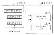
상술한 바와 같은 촬영 장치(1)에 있어서의 촬상 동작에 의해 메모리(11)내에 기록된 피사체 분광 화상은 외부 I/F(17)를 통해 처리 장치(2)에 송신되고, 이 처리 장치(2)에 내장되는 화상 메모리부(32)(도 12 참조)에 기록되어, 소정의 소프트웨어에 의해 동작하는 연산 장치(21)에 의해, 색재현이나 화상 처리가 행해지도록 되어 있다. 그 처리 결과는 이 처리 장치(2)의 디스플레이(22)에 표시되거나, 또는 상기 LCD 모니터(16)에 전송되어 표시된다.The subject spectroscopic image recorded in the
도 12는 처리 장치(2)에 있어서의 디스플레이(22)에 표시하기 위한 색재현을 행하는 구성을 도시한 블록도이다.FIG. 12 is a block diagram showing the configuration of color reproduction for display on the
이 처리 장치(2)는 촬영 장치(1)로부터 입력되는 피사체 분광 화상이 상기 제1 LED(6a)∼제6 LED(6f)의 어느 것에 의해 조명된 것인가에 따라서 화상 메모리부(32)내의 기억 영역을 분류하는 화상 분류부(31)와, 이 화상 분류부(31)에 의해 분류된 피사체 분광 화상을 각각 기억하는 기억 영역인 제1 메모리(32a)∼제6 메모리(32f)를 구비한 화상 메모리부(32)와, 이 화상 메모리부(32)에 기억된 피사체 분광 화상을 판독하여 디스플레이(22)에 있어서 고도로 색재현된 화상을 표시하기 위한 디스플레이 화상 데이터를 산출하여 출력하는 색재현 연산부(33)를 가지며, 이들은 예를 들면 도 1에 도시한 연산 장치(21)에 포함되어 있으며, 또한, 상기 색재현 연산부(33)로부터 출력되는 디스플레이 화상 데이터에 기초하여 고도로 색재현된 화상을 표시하는 상기 디스플레이(22)를 갖고 구성되어 있다.This
상기 색재현 연산부(33)는 촬영 장치(1)에 관한 프로파일을 기억하는 입력 프로파일 기억부(33b)와, 상기 화상 메모리부(32)의 제1 메모리(32a)∼제6 메모리(32f)에 기억된 피사체 분광 화상을 판독하여 상기 입력 프로파일 기억부(33b)에 기억되어 있는 입력 프로파일과 내부에 설정된 소정의 등색 함수를 이용하여 추정 연산을 행함으로써 XYZ 삼자극값의 화상 데이터를 생성하는 XYZ 추정 연산부(33a)와, 상기 디스플레이(22)에 관한 프로파일을 기억하는 디스플레이 프로파일 기억부(33d)와, 상기 XYZ 추정 연산부(33a)에 의해 추정된 XYZ 삼자극값의 화상 데이터와 상기 디스플레이 프로파일 기억부(33d)에 기억되어 있는 디스플레이 프로파일을 이용하여 연산을 행함으로써 상기 디스플레이(22)에 출력하기 위한 디스플레이 화상 데이터를 생성하는 디스플레이값 변환부(33c)를 갖고 구성되어 있다.The color reproduction calculation unit 33 is provided in an input
상기 입력 프로파일 기억부(33b)에 기억되어 있는 입력 프로파일은, 예를 들면 일본 특허공개 2000-341499호 공보에 기재되어 있는 것으로, 촬상에 이용한 CCD(8)의 분광 감도를 포함하는 촬영 장치(1)의 특성이나 설정(화상 입력 장치), 피사체를 촬영할 때의 조명광의 스펙트럼 데이터(촬영 조명광 정보), 생성한 피사체 화상을 관찰하는 디스플레이(22)가 설치되어 있는 장소의 조명광의 스펙트럼 데이터(관찰 조명광 정보), 촬영한 피사체의 분광 반사율의 통계적 성질 등의 정보(피사체 특성 정보) 등의 정보에 기초하여 산출된 것이다.The input profile stored in the said input profile memory |
도 14는 처리 장치(2)에 있어서 입력 프로파일을 생성하는 구성예를 도시한 블록도이다.14 is a block diagram showing a configuration example of generating an input profile in the
상기 입력 프로파일은 도 14에 도시한 바와 같이, 촬영 장치(1)로부터 취득한 각 데이터 등에 기초하여 처리 장치(2)에 있어서 생성하도록 해도 된다.As shown in FIG. 14, the input profile may be generated in the
촬영 장치(1)에 있어서 취득되는 데이터로서는, 조명광 스펙트럼 데이터, 카메라 특성 데이터, 피사체 특성 데이터 등이 예시된다.As data acquired in the
상기 조명 스펙트럼 데이터는 예를 들면 피사체를 촬영할 때의 조명에 관한 스펙트럼 데이터이며, 접촉식인 경우에는 촬영 장치(1)에 내장한 각 LED(6a∼6f)의 스펙트럼 데이터가 된다. 비접촉식의 경우에는 피사체를 촬영하는 경우의 외부 조명의 스펙트럼 데이터 등도 더 포함하게 된다.The illumination spectrum data is, for example, spectrum data relating to illumination when a subject is photographed, and in the case of a contact type, becomes spectrum data of each of the
상기 카메라 특성 데이터는 포커스값 등을 포함하는 촬영 광학계(7)의 특성, CCD(8)의 촬상 특성, 셔터 속도, 조리개값 등의 제반 특성을 포함하여 구성되어 있다.The said camera characteristic data is comprised including the characteristic of the imaging
상기 피사체 특성은 피사체가 예를 들면, 치아, 피부, 도료 등인 경우의 분광 통계 데이터 등으로 구성되어 있으며, 고정밀도의 입력 프로파일을 작성하기 위하여, 조작 스위치(14) 등에 피사체 지시 조작부를 형성하여, 피사체를 지정하기 위한 피사체 지정 신호를 입력하도록 해도 된다.The subject characteristic is composed of spectroscopic statistical data when the subject is, for example, teeth, skin, paint, and the like. In order to create a high-precision input profile, a subject instructing operation portion is formed on the
이들 데이터에 기초하여 입력 프로파일을 생성하는 처리 장치(2)의 구성은 도 14에 도시한 바와 같이, 상기 조명 스펙트럼 데이터, 카메라 특성 데이터, 피사체 특성 데이터를 읽어들여서 연산을 행함으로써 입력 프로파일을 생성하는 입력 프로파일 연산부(33e)와, 이 입력 프로파일 연산부(33e)에 의해 생성된 입력 프로파일을 기억하는 상기 입력 프로파일 기억부(33b)를 갖고 구성되어 있다.The configuration of the
이와 같은 구성에 의해, 처리 장치에 접속되는 촬영 장치(1)를 서로 다른 개체, 기종 등의 것으로 변경(촬영 광학계(7)의 변경 등)하거나, 촬영을 행하는 환경 조명이 변화되거나, 촬영 대상이 되는 피사체를 여러가지로 변경시키거나 해도, 적응적으로 고도의 색재현을 행하는 것이 가능해진다.With such a configuration, the photographing
또한, 상기 디스플레이 프로파일 기억부(33d)에 기억되어 있는 디스플레이 프로파일은 디스플레이(22)의 표시 원색값(예를 들면 디스플레이(22)가 RGB 모니터인 경우에는 RGB 원색값)의 색도값, 디스플레이(22)의 톤 커브 등의 정보에 기초하여 산출된 것이다. 또한, 디스플레이는 일본 특허공개 2000-338950호 공보에 기재되어 있는 다원색의 색재현 시스템을 이용해도 무방하다.In addition, the display profile stored in the display
또한, 도 13은 취득된 피사체 분광 화상에 기초하여 피사체에 관한 화상 판별을 행하기 위한 구성예를 도시한 블록도이다.13 is a block diagram showing a configuration example for performing image discrimination on a subject based on the acquired subject spectroscopic image.
상기 화상 메모리부(32)의 제1∼제6 메모리(32a∼32f)에 기억된 피사체 분광 화상은 화상 판별 연산부(34)에 의해 판독되어 피사체에 관한 화상 판별이 행해지고, 그 판별 결과가 출력되어 상기 디스플레이(22)에 표시되도록 되어 있다. 또한, 화상의 판별 연산이 네트워크를 통해 행해지고, 결과가 LCD 모니터(16)에 표시되도록 구성되어 있어도 무방하다.The subject spectroscopic images stored in the first to
상기 화상 판별 연산부(34)는 피사체에 관한 각종 분류/판정/진단/해석 등을 행하기 위한 판별 함수를 기억하는 판별 함수 기억부(34b)와, 상기 화상 메모리부(32)의 제1∼제6 메모리(32a∼32f)에 기억된 6장의 피사체 분광 화상의 전부 또는 그 중에서 선택되는 1장 이상의 피사체 분광 화상을, 이 판별 함수를 이용하여 연산함으로써 판별 결과를 산출하여 상기 디스플레이(22)에 표시하기 위한 판별 결과 표시용 화상 데이터를 생성하는 판별 연산부(34a)를 갖고 구성되어 있다.The image discrimination operation unit 34 includes a discrimination
또한, 상기 판별 함수는 이 화상 처리 시스템을 어떠한 용도로 이용할 것인가에 따라서, 여러가지 치환을 행하는 것이 가능하다. 예를 들면, 치과에 한정하여, 치아의 백색도의 등급 판정이나, 색조 판별, 피부과에 한정하여, 피부 표면의 피부 구멍이나 피부 돌출 부분의 상관 관계, 엔트로피 해석 등으로 치환할 수 있다. 따라서, 상기 판별 함수 기억부(34b)를, 재기록 가능 또는 추기 가능한 기억 매체에 의해 구성하여, 용도에 따라서 사용하는 판별 함수를 추가 기입하거나, 또는 재기록하도록 하면 된다. 이와 같은 판별 함수의 구체적인 예로서는, 일본 특허공개 평7-120324호 공보에 기재된 바와 같은 처리를 행하는 함수를 예시할 수 있다.In addition, the determination function can perform various substitutions depending on the purpose of using this image processing system. For example, it is possible to substitute the dental whiteness for grade evaluation, color tone discrimination, dermatology, and the like by correlation of skin pores and protrusions of the skin surface, entropy analysis, and the like. Therefore, the determination
이 도 13에 도시한 화상 판별 연산부(34)는 상기 도 12에 도시한 색재현 연산부(33) 대신에 처리 장치(2)에 구비시키도록 해도 된다. 또는, 도 12에 도시한 색재현 연산부(33)와 함께 이 처리 장치(2)내에 형성하여, 이들에 의해 처리를 병렬하여 동시에 행하게 하거나, 또는 필요한 것만을 선택적으로 전환하여 처리를 행하게 해도 무방하다.The image discrimination calculating unit 34 shown in FIG. 13 may be provided in the
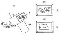
다음으로, 도 15는 촬영 장치(1)의 LCD 모니터(16)에 있어서의 표시예를 도시한 도면이다.Next, FIG. 15 is a diagram showing an example of display on the LCD monitor 16 of the photographing
LCD 모니터(16)는 예를 들면 도 15의 (A)에 도시한 바와 같이, 촬영 장치(1)의 하우징(5)의 배면측의, 파지부(把持部)(5b)의 상부에 배치되어 있으며, 도 15의 (B)나 도 15의 (C)에 도시한 바와 같은 화상을 표시하도록 되어 있다. 또한, 여기서는, 손을 피사체로 하여 촬영하고 있는 예를 도시하고 있다.For example, as shown in FIG. 15A, the
먼저, 도 15의 (B)는 상기 모니터용 화상 취득 모드에 의해 촬상된 동화상을 표시하고 있을 때의 모습을 도시하고 있으며, 이에 따라, LED 모니터(16)가 파인더로서의 기능을 하도록 되어 있다.First, Fig. 15B shows a state when the moving image captured by the monitor image acquisition mode is displayed, whereby the LED monitor 16 functions as a finder.
다음으로, 도 15의 (C)는 예를 들면 상기 화상 판별 연산부(34)에 의한 피사체 화상의 판별 결과를 표시하고 있는 모습을 도시하고 있다. 여기서는, 피사체의 ID 번호(예를 들면 의료 분야의 진단 지원 시스템에 있어서의 환자 번호 등)과, 화상 판별에 의해 얻어진 수치 해석 결과의 그래프(예를 들면 치료 경과 등)가 표시되어 있다. LCD 모니터(16)에는 이들에 한정되지 않고, 색재현 화상, 환자 챠트, 각종 데이터, 도표 등의 여러가지 정보를 표시하는 것이 가능하게 되어 있다.Next, FIG. 15C shows a state in which the result of discriminating the subject image is displayed by the image discrimination calculating section 34, for example. Here, the ID number of the subject (for example, the patient number in the diagnosis support system in the medical field) and the graph (for example, the course of treatment) of the numerical analysis result obtained by image discrimination are displayed. The LCD monitor 16 is not limited to these, and it is possible to display various information such as color reproduction images, patient charts, various data, charts, and the like.
이렇게 하여, 상기 LCD 모니터(16)는 촬영 부위를 선택할 때의 파인더로서 기능하거나, 색재현 결과나 분류/판정/진단/해석 등의 결과를 표시할 때의 모니터로서 기능하도록 되어 있다.In this way, the LCD monitor 16 functions as a finder when selecting a photographing site or as a monitor when displaying results of color reproduction, classification, judgment, diagnosis, analysis, or the like.
한편, 처리 장치(2)의 디스플레이(22)는 핸디 타입의 촬영 장치(1)에 설치된 LCD 모니터(16)보다도 대면적이고 고정밀한 타입의 것인 경우가 많기 때문에, 이 처리 장치(2)에 있어서 목적에 따라서 실행되는 처리 소프트웨어의, 기동 표시, 조건 설정 표시, 피사체 ID 등의 정보를 입력하기 위한 GUI 표시나, 환자의 경력 표시, 전회 정보 등의 피사체 정보 표시, 처리 결과 표시 등을 행하도록 해도 된다.On the other hand, since the
상기 네트워크(3)에는 예를 들면 외부 데이터베이스가 접속되어 있으며, 이 외부 데이터베이스로부터 피사체 정보를 처리 장치(2)에 취득하거나, 또는 처리 장치(2)에 있어서 행한 처리 결과를 외부 데이터베이스에 저장하는 등을 행하도록 해도 된다. 이 때에는 시큐러티를 확보하기 위하여, 처리 장치(2)와 외부 시스템을 네트워크(3)를 통해 접속할 때에 상호 인증을 행하거나, 피사체 데이터에 시큐러티 레벨을 형성하여 레벨에 따른 인증을 행하도록 구성하는 것도 가능하다.For example, an external database is connected to the
다음으로, 도 16은 화상 처리 시스템을 사용할 때의 모습의 일례를 도시한 도면이다.Next, FIG. 16 is a diagram showing an example of the state when using an image processing system.
상기 촬영 장치(1)는 경량 소형이 되도록 구성되어 있으며, 예를 들면 한손으로 파지부(5b)를 잡아서, 촬상계가 설치된 하우징(5)의 선단측을, 패드부(4)를 통해 피사체의 촬영 대상 부위에 닿게 함으로써, 촬상을 행할 수 있도록 되어 있다.The photographing
상기 패드부(4)는 상술한 바와 같이, 착탈 가능하고 디스포즈가능한 부재로 되어 있으며, 외부로터의 광이 피사체의 촬영 대상 부위에 닿는 것을 차폐하고 있다.As described above, the
상기 파지부(5b)의 상부, 예를 들면 검지로 조작 가능한 위치에, 상기 조작 스위치(14)에 포함되는 촬영 버튼(14a)이 형성되어 있으며, 상기 LCD 모니터(16)에서 촬영하고자 하는 부위를 특정한 후에, 이 촬영 버튼(14a)을 누름으로써, 상술한 바와 같이 모니터용 화상 취득 모드에서 분광 화상 취득 모드로 이행하여, 분광 화상의 촬상이 행해지도록 되어 있다.In the upper part of the holding
취득된 분광 화상은 처리 장치(2)에 있어서 데이터 처리가 행해져서 디스플레이(22)에 표시되지만, 필요에 따라서 설정 등을 행함으로써, 촬영 장치(1)의 LCD 모니터(16)에 처리 장치(2)에 있어서의 처리 결과를 표시하도록 해도 되는 것은 상술한 바와 같다.The acquired spectroscopic image is displayed on the
또한, 도 16에 도시한 예에 있어서는, 처리 장치(2)를, 디스플레이가 부착된 노트형의 퍼스널 컴퓨터로서 도시하고 있다. 이와 같은 경우에는, 노트형의 퍼스널 컴퓨터에 구비되어 있는 RS-232C, USB, IEEE1394 등의 인터페이스(I/F)를 통해, 상기 네트워크(3)에 접속하도록 하면 된다.In addition, in the example shown in FIG. 16, the
이와 같은 제1 실시 형태에 따르면, 화상 처리 시스템의 촬영 장치내에 가시광역에 있어서 각각 다른 분광 분포를 갖는 6종류의 LED를 형성하여, 외광을 차단하면서 이들을 발광시킴으로써, 피사체 분광 화상을 촬상할 수 있다. 이 때, 광원으로서 LED 등의 소형 경량의 반도체 발광 소자를 이용하고 있기 때문에, 촬영 장 치를 소형화할 수 있으며, 핸디 타입의 것을 작성하는 것도 가능해진다.According to this first embodiment, the subject spectroscopic image can be imaged by forming six types of LEDs having different spectral distributions in the visible region in the imaging region of the image processing system and emitting them while blocking external light. . At this time, since a small and light-weight semiconductor light emitting element such as LED is used as the light source, the photographing device can be downsized, and it is also possible to create a handy type one.
또한, 처리 장치에 의해 처리를 행함으로써, 고도로 색재현된 화상을 디스플레이에 표시하는 것이 가능해진다.In addition, by performing the processing by the processing apparatus, it becomes possible to display a highly color reproduced image on the display.
또한, LED의 발광 순서나 발광시키는 LED를 지정함으로써, 통상의 RGB 동화상을 비롯하여, 여러가지 목적에 이용하는 화상을 촬상하는 것이 가능해진다.In addition, by specifying the light emission order of the LEDs and the LEDs to emit light, it becomes possible to capture an image used for various purposes including a normal RGB moving image.
부가하여, 모노크롬 CCD를 이용하고 있기 때문에, 코스트를 약간 저감할 수 있음과 아울러, 각 색의 화상 데이터가 누락 화소를 발생시키지 않고 1화면씩 취득되기 때문에, 보간 처리를 생략하는 것이 가능해진다.In addition, since the monochrome CCD is used, the cost can be slightly reduced, and since interpolation processing can be omitted since image data of each color is acquired one by one without generating missing pixels.
도 17 내지 도 20은 본 발명의 제2 실시 형태를 도시한 것으로, 도 17은 화상 처리 시스템의 구성을 도시한 블록도, 도 18은 풀 모드 및 판독 2배속 모드에 있어서의 판독 모습을 도시한 타이밍차트, 도 19는 2/4라인 2배속 모드 및 2/8라인 4배속 모드에 있어서의 판독되는 라인의 모습을 도시한 도면, 도 20은 촬영 모드를 설정할 때의 동작을 도시한 플로우차트이다.17 to 20 show a second embodiment of the present invention, FIG. 17 is a block diagram showing the configuration of an image processing system, and FIG. 18 shows a reading state in the full mode and the read double speed mode. Fig. 19 is a view showing the state of lines read in the 2/4 line double speed mode and the 2/8 line quad speed mode, and Fig. 20 is a flowchart showing the operation when setting the shooting mode. .
이 제2 실시 형태에 있어서, 상술한 제1 실시 형태와 동일한 부분에 대해서는 동일한 부호를 붙이고 설명을 생략하고, 주로 다른 점에 대해서만 설명한다.In this 2nd Embodiment, the same code | symbol is attached | subjected about the same part as 1st Embodiment mentioned above, description is abbreviate | omitted, and only a different point is mainly demonstrated.
이 제2 실시 형태는 상술한 제1 실시 형태를 기본 구성으로 하고, 또한, 전면(前面)에 컬러 필터 어레이(CFA)(19)를 구비한 컬러 CCD로부터의 화상 판독 속도를 조정할 수 있도록 구성한 것이다.This second embodiment is based on the first embodiment described above, and is configured such that an image reading speed from a color CCD having a color filter array (CFA) 19 on its front surface can be adjusted. .
화상 판독 속도는 표시 속도와 관련되어 있으며, 표시 속도를 판독 속도 이상으로 빠르게 할 수는 없다.The image reading speed is related to the display speed, and the display speed cannot be made faster than the reading speed.
일반적으로, 화상을 모니터하는 경우에는, 30화상/초 정도 이상의 표시 간격이 바람직하지만, 원색수 N이 증가하면 그에 따라서 비례적으로 표시 간격이 길어지고, 플리커 상태가 발생하거나, 또는 각 원색 화상 취득 시간차에 따른 큰 화상 위치 어긋남이 생기는 경우가 있다.In general, in the case of monitoring an image, a display interval of about 30 images / second or more is preferable, but when the number of primary colors N increases, the display interval lengthens proportionally, a flicker state occurs, or each primary color image is acquired. Large image position shift may occur due to time difference.
따라서, 본 실시 형태는 표시 간격이 길어지는 것을 회피하여, 판독 원색수 N에 의하지 않고 표시 간격을 일정하게 하기 위하여, 도 17에 도시한 바와 같이, 카메라 제어 I/F(12A)에 의해 CCD(8A)로부터의 화상 판독 속도를 조정하도록 한 것이다.Therefore, in this embodiment, in order to avoid the display interval becoming longer and to make the display interval constant regardless of the read primary color number N, as shown in Fig. 17, the camera control I /
도 20을 참조하여, 촬영 모드를 설정할 때의 동작에 관하여 설명한다.Referring to Fig. 20, the operation when setting the shooting mode will be described.
조작 스위치(14)로부터 촬영 모드를 선택하는 조작 입력이 있으면(단계 S21), CPU(18)가 그것을 검출하여, 메모리(11)내의 기록 에리어의 일부에, 설정할 촬영 모드나 그것과 관련된 정보 등을 기록함과 아울러(단계 S22), 카메라 제어 I/F(12A)에 촬영 모드를 변경하도록 제어를 행하게 하는 명령을 발행한다(단계 S23).If there is an operation input for selecting a shooting mode from the operation switch 14 (step S21), the
카메라 제어 I/F(12A)는 이 지령을 받아서, CCD(8A)의 구동을 제어하여, 촬영 모드를 변경하도록 되어 있다. 이 때에는 카메라 제어 I/F(12)는 CCD(8A)의 동작과 연동시켜서 LED 드라이버(13)를 제어함으로써, 각 LED(6a∼6f)의 발광량도 함께 조정하도록 되어 있다.The camera control I /
이 촬영 장치(1)에 있어서 설정 가능한 촬영 모드는 예를 들면 다음과 같이 되어 있다.The imaging mode which can be set in this
(1) 풀 모드(1) pull mode
(2) 판독 2배속 모드(2) read double speed mode
(3) 2/4라인 2배속 모드(3) 2/4 line double speed mode
(4) 2/8라인 4배속 모드(4) 2/8 line 4x mode
(5) 2/16라인 8배속 모드(5) 2/16 line 8x mode
(6) 제1 중앙부 주사 모드(6) first center scan mode
(7) 제2 중앙부 주사 모드(7) second center scan mode
(8) 제3 중앙부 주사 모드(8) third center scan mode
(9) 제4 중앙부 주사 모드(9) fourth center scan mode
(10) 제1 중앙부 고속 주사 모드(10) first central fast scanning mode
(11) 제2 중앙부 고속 주사 모드(11) second center fast scanning mode
"풀 모드"는 도 18의 (A)에 도시한 바와 같이, CCD(8A)의 전체 주사 라인의 전체 화소에 대하여 통상의 속도로 순차로 판독을 행해가는 통상의 모드이다. 또한, 여기서는, 제1 LED(6a), 제3 LED(6c), 제5 LED(6e)를 동시에 발광시키는 프레임과, 제2 LED(6b), 제4 LED(6d), 제6 LED(6f)를 동시에 발광시키는 프레임에 의해 각 프레임이 구성되어 있지만, 이와 같은 발광에 의해 6원색 화상을 취입하는 수단에 대해서는, 나중의 제3 실시 형태에서 설명한다.As shown in Fig. 18A, the " full mode " is a normal mode in which all pixels of all the scanning lines of the CCD 8A are sequentially read at a normal speed. In addition, here, the frame which simultaneously emits the
"판독 속도 2배속 모드"는 도 18의 (A)에 도시한 통상의 모드에 대하여, 도 18의 (B)에 도시한 바와 같이, CCD(8A)의 전체 주사 라인의 전체 화소에 대하여 통상의 2배의 속도로 순차로 판독을 행해가는 모드로 되어 있다. 또한, 여기서는, 2 배속의 판독을 예로 들었지만, 이것에 한정되지 않고 적절한 배수이어도 되고, 또한 가변 배수로 해도 무방하다.The "reading speed double speed mode" is a normal mode for all the pixels of all the scanning lines of the CCD 8A, as shown in Fig. 18B for the normal mode shown in Fig. 18A. The mode reads sequentially at twice the speed. In addition, although the reading of double speed was mentioned here as an example, it is not limited to this, A suitable multiple may be sufficient and may be a variable multiple.
"2/4라인 2배속 모드"는 4라인마다 2라인만을 주사함으로써, 1프레임을 판독하는데 소요되는 시간을 절반으로 하는 것이고, 수직 방향의 분해능은 절반이 되지만, 전체 유효 에리어의 화상을 취득하는 것이 가능하게 되어 있다.In the "2/4 line double speed mode", only two lines are scanned every four lines, so that the time required to read one frame is halved, and the resolution in the vertical direction is halved. It is possible.
"2/8라인 4배속 모드"는 또한, 8라인마다 2라인만을 주사함으로써, 1프레임을 판독하는데 소요되는 시간을 통상 모드의 1/4로 하는 것이다.The " 2/8 line quadruple mode " also means that the time required to read one frame is 1/4 of the normal mode by scanning only two lines every eight lines.
"2/16 라인 8배속 모드"는 마찬가지로, 16라인마다 2라인만을 주사함으로써, 1프레임을 판독하는데 소요되는 시간을 통상 모드의 1/8로 하는 것이다.Similarly, in the "2/16 line 8x speed mode", only two lines are scanned every 16 lines, so that the time required to read one frame is 1/8 of the normal mode.
"제1 중앙부 주사 모드"는 도 19의 (A)에 도시한 바와 같이 전체 주사 라인의 라인수를 S로 했을 때에, 유효 에리어 중의, 중앙부의 S/2라인의 부분만을 주사함으로써, 1프레임을 판독하는데 소요되는 시간을 절반으로 하는 것이다.In the first center scanning mode, as shown in FIG. 19A, when the number of lines of all the scanning lines is S, only one portion of the center S / 2 line in the effective area is scanned to scan one frame. The time required for reading is halved.
"제2 중앙부 주사 모드"는 도 19의 (B)에 도시한 바와 같이 전체 주사 라인의 라인수를 S로 했을 때에, 유효 에리어 중의, 중앙부의 S/4라인의 부분만을 주사함으로써, 1프레임을 판독하는데 소요되는 시간을 1/4로 하는 것이다.In the second center scanning mode, as shown in Fig. 19B, when the number of lines of all the scanning lines is set to S, only one portion of the center S / 4 line is scanned in the effective area, thereby scanning one frame. The time required for reading is 1/4.
"제3 중앙부 주사 모드"는 마찬가지로, 유효 에리어 중의, 중앙부의 S/8라인의 부분만을 주사함으로써, 1프레임을 판독하는데 소요되는 시간을 1/8로 하는 것이다.Similarly, in the "third center scanning mode", the time required for reading one frame is set to 1/8 by scanning only the portion of the center S / 8 line in the effective area.
"제4 중앙부 주사 모드"는 마찬가지로, 유효 에리어 중의, 중앙부의 S/16라인의 부분만을 주사함으로써, 1프레임을 판독하는데 소요되는 시간을 1/16으로 하 는 것이다.Similarly, in the "fourth center scan mode", by scanning only the portion of the S / 16 line in the center of the effective area, the time required to read one frame is 1/16.
"제1 중앙부 고속 주사 모드"는 상기 도 19의 (A)에 도시한 바와 같은, 유효 에리어 중의 중앙부의 S/2라인의 부분만을, 통상의 2배의 속도로 주사함으로써, 1프레임을 판독하는데 소요되는 시간을 1/4로 하는 것이다.The "first center fast scanning mode" reads one frame by scanning only the portion of the center S / 2 line in the effective area as shown in Fig. 19A above at a normal double speed. The time required is 1/4.
"제2 중앙부 고속 주사 모드"는 상기 도 19의 (B)에 도시한 바와 같은, 유효 에리어 중의 중앙부의 S/4라인의 부분만을, 통상의 2배의 속도로 주사함으로써, 1프레임을 판독하는데 소요되는 시간을 1/8로 하는 것이다.The "second center portion high speed scan mode" reads one frame by scanning only the portion of the S / 4 line in the center portion of the effective area as shown in Fig. 19B above at a normal double speed. The time required is 1/8.
이들에 한정되지 않고, 또 다른 수단에 의한 고속 스캔을 행하는 것도 가능하고, 상기를 포함하여 이하와 같이 정리할 수 있다.It is not limited to these, It is also possible to perform a high speed scan by another means, and it can summarize as follows including the above.
먼저 첫째, 단순한 스캔 속도의 고속화이다. 이것은 예를 들면 판독 개시를 지시하는 트리거 신호의 타이밍을 조정함으로써 행할 수 있다. 예를 들면, 1프레임의 표시 시간을 1/30초로 하는 예에서는, 각 원색(N원색으로 함)의 판독 시간이 1/30/N이 되도록 트리거 신호의 타이밍을 설정함으로써 달성된다.Firstly, the speed of the simple scan is increased. This can be done, for example, by adjusting the timing of the trigger signal instructing read start. For example, in the example in which the display time of one frame is 1/30 second, it is achieved by setting the timing of the trigger signal so that the read time of each primary color (N primary color) is 1/30 / N.
둘째, 씨닝(thinning) 스캔에 의한 고속화이다. 상기 제1 고속화 수단에서는, 촬상 소자에 의해 고속화에 한계가 생긴다. 이에 비하여, 이 씨닝을 행하는 경우에는, 화질은 저하되지만, 안정된 주사를 행하여 고속화를 도모할 수 있기 때문에, 프레임 레이트가 떨어지지 않고, 표시에 플리커가 생길 수 없다. 이 씨닝의 예로서는, 상술한 바와 같은, 라인 단위로 일정 주기, 또는 일정 범위에서 씨닝하는 수단 이외에, 화소 단위로 씨닝하는 것도 가능하고, 촬상 소자가 XY 어드레스형의 것인 경우에는, 정밀하게 원하는 화소만을 판독하는 것도 가능하다.Second, speeding up by thinning scan. In the first speed-up means, the speed-up is limited by the imaging element. On the other hand, when this thinning is performed, the image quality is lowered, but since stable scanning can be performed to speed up, the frame rate does not decrease, and flicker cannot occur in the display. As an example of this thinning, in addition to the means for thinning in a fixed period or a predetermined range in line units as described above, thinning can also be carried out in pixel units. When the image pickup device is an XY address type, the desired pixel is precisely desired. It is also possible to read only.
셋째, 원색에 따라서 프레임 레이트를 다르게 함에 의한 고속화이다. 통상의 RGB 컬러 필터 등을 구비한 CCD에 있어서도, 휘도 신호에 가까운 녹색(G)의 화소는 적색(R)이나 청색(B)의 화소의 2배의 수만큼 배열되어 있는 것이 많다. 이와 같은 점을 고려하여, 6원색 중의 녹색(G)에 가까운 프레임은 이것 이외의 색의 프레임의 2배의 수만큼 판독하도록 하는 것이 고려된다. 물론 이것에 한정되지 않고, 사용 목적에 따라서, 특정한 원색의 프레임을 많이 판독하도록 하거나, 필요도에 따라서 판독하는 레이트를 단계적으로 다르게 하면 된다.Third, the speed is increased by changing the frame rate according to the primary colors. Even in a CCD equipped with a normal RGB color filter or the like, the green (G) pixels near the luminance signal are often arranged by twice the number of the red (R) or blue (B) pixels. In view of such a point, it is considered that a frame close to the green (G) of the six primary colors is read by twice the number of the frames of colors other than this. Of course, it is not limited to this, According to a use purpose, it is good to read many frames of a specific primary color, or you may change a reading rate step by step as needed.
이와 같은 제2 실시 형태에 따르면, 상술한 제1 실시 형태와 거의 동일한 효과를 발휘함과 아울러, 판독 속도를 변경함으로써, 일정한 표시 속도를 확보하는 것이 가능해지고, 고도의 색재현시에도 움직임이 자연스러운 동화상을 표시하는 것이 가능해진다.According to this second embodiment, while exhibiting almost the same effects as in the first embodiment described above, by changing the reading speed, it is possible to ensure a constant display speed, and the movement is natural even at high color reproduction. It becomes possible to display moving images.
도 21 내지 도 36은 본 발명의 제3 실시 형태를 도시한 것으로, 도 21은 화상 처리 시스템의 구성을 도시한 블록도, 도 22는 화상 처리 시스템을 사용할 때의 모습의 일례를 도시한 도면이다. 이 제3 실시 형태에 있어서, 상술한 제1, 제2 실시 형태와 동일한 부분에 대해서는 동일한 부호를 붙이고 설명을 생략하고, 주로 다른 점에 대해서만 설명한다.21 to 36 show a third embodiment of the present invention, FIG. 21 is a block diagram showing the configuration of an image processing system, and FIG. 22 is a diagram showing an example of the state when using an image processing system. . In this 3rd Embodiment, the same code | symbol is attached | subjected about the same part as 1st, 2nd Embodiment mentioned above, description is abbreviate | omitted, and only a different point is mainly demonstrated.
이 제3 실시 형태는 상술한 제1 실시 형태를 기본 구성으로 하며, CCD의 촬상면상에 3밴드의 컬러 필터 어레이를 더 배열한 구성으로 한 것이다.This third embodiment is based on the first embodiment described above, and has a configuration in which a three-band color filter array is further arranged on the imaging surface of the CCD.
즉 도 21과 도 22에 도시한 바와 같이, 촬영 장치(1)는 촬상 광학계(7)에 의해 피사체상이 결상되는 광로상의 CCD(8) 근방에, 예를 들면 RGB 3밴드의 컬러 필 터 어레이(도면에서 CFA로 약칭함)(19)가 배열되어 있으며, 촬상 소자부로서 이른바 단판식의 컬러 촬상 소자가 구성되어 있다.That is, as shown in Figs. 21 and 22, the photographing
도 23은 LED(6a∼6f)의 발광 스펙트럼 및 컬러 필터 어레이(19)를 통한 CCD(8)의 분광 감도 특성을 도시한 선도이다.FIG. 23 is a diagram showing the spectral sensitivity characteristics of the
제1 실시 형태에 있어서도 도시한 바와 같은, 곡선 fL1∼fL6에 의해 표시되는 6원색 LED의 발광 스펙트럼에 대하여, 컬러 필터 어레이(19)의 투과율 분포 및 CCD(8)의 수광 감도 분포에 의해 얻어지는 전체적인 분광 감도 특성은 도시한 곡선 fSB, fSG, fSR으로 되어 있다.As also shown in the first embodiment, the overall emission obtained by the transmittance distribution of the
이들 중의 청색 컬러 어레이에 해당하는 분광 밴드역을 나타낸 곡선 fSB은 곡선 fL1, fL2의 2개를 포함하여 제1 LED(6a)와 제2 LED(6b)의 발광에 의한 광을 감수할 수 있으며, 녹색 컬러 필터에 해당하는 분광 밴드역을 나타낸 곡선 fSB은 곡선 fL3, fL4의 2개를 포함하여 제3 LED(6c)와 제4 LED(6d)의 발광에 의한 광을 감수할 수 있으며, 적색 컬러 필터에 해당하는 분광 밴드역을 나타낸 곡선 fSR은 곡선 fL5, fL6의 2개를 포함하여 제5 LED(6e)와 제6 LED(6f)의 발광에 의한 광을 감수할 수 있도록 구성되어 있다.The curve fSB showing the spectral band region corresponding to the blue color array among them can accept light due to the light emission of the
다만, 전체적인 분광 감도 특성이 서로 독립적으로 분리되어 있을 필요는 없고, 주변 부분에 있어서 서로 일부가 겹쳐지도록 되어 있어도 무방하다. 또한, 제1 실시 형태와 마찬가지로, 제1 LED(6a)∼제6 LED(6f)의 각 발광 스펙트럼도, 일부가 겹쳐지는 발광 스펙트럼이어도 무방하다. 물론, LED의 종류도 6종류에 한정되는 것은 아니고, 적절한 종류수의 LED의 조합을 채용할 수 있는 것도 동일하다.However, the overall spectral sensitivity characteristics do not need to be separated independently from each other, and some of them may overlap each other in the peripheral portion. In addition, similarly to the first embodiment, the emission spectra of the
다음으로, 화상을 취득할 때의 동작에 관하여 설명한다.Next, the operation at the time of acquiring an image is demonstrated.
이 화상 처리 시스템에 있어서는, 상술한 제1 실시 형태와 마찬가지로, 화상을 취득할 때에, 모니터용 화상 취득 모드와 분광 화상 취득 모드를 전환하여 행하도록 되어 있다.In the image processing system, as in the first embodiment described above, when the image is acquired, the monitor image acquisition mode and the spectroscopic image acquisition mode are switched.
도 24, 도 26, 도 27을 참조하여, 분광 화상 취득 모드의 동작에 관하여 설명한다. 도 24는 6밴드의 분광 화상을 생성할 때의 프레임별 분광 화상의 분광 특성을 도시한 선도, 도 26은 6밴드 분광 화상 취득에 있어서의 각 LED의 발광 및 촬상 소자의 화상 취득의 동작을 도시한 플로우차트, 도 27은 6밴드 분광 화상 취득에 있어서의 각 LED의 발광 및 촬상 소자의 화상 취득의 동작 모습을 도시한 타이밍차트이다.24, 26, and 27, the operation of the spectroscopic image acquisition mode will be described. FIG. 24 is a diagram showing the spectral characteristics of the spectroscopic images for each frame when generating a six-band spectroscopic image, and FIG. 26 shows the operation of light emission of each LED and the image acquisition operation of the imaging device in the six-band spectroscopic image acquisition. FIG. 27 is a timing chart showing an operation of light emission of each LED and image acquisition of the imaging device in 6-band spectroscopic image acquisition.
제1 실시 형태에 있어서 설명한 바와 같이, 촬영 버튼(14a)이 눌려져서 분광 화상 취득 모드로 전환되면, 분광 화상의 촬상을 개시하는 판단을 행한다(단계 S31).As described in the first embodiment, when the photographing button 14a is pressed to switch to the spectroscopic image acquisition mode, determination is made to start capturing the spectroscopic image (step S31).
여기서, 분광 화상의 촬상이 개시되면, 프레임 N의 화상을 취입하고, 그 후에 프레임 N+1의 화상을 취입한다.Here, when imaging of a spectral image is started, the image of frame N is taken in, and the image of frame N + 1 is taken in after that.
먼저, 프레임 N의 화상의 취입이 개시되면, 제1 LED(6a), 제3 LED(6c), 제5 LED(6e)를 동시에 점등시키고(도 24의 (A) 참조)(단계 S32), 점등이 개시된 후에 CCD(8)에 의한 촬상을 개시한다(도 27 참조)(단계 S33)First, when the taking-in of the image of the frame N is started, the
CCD(8)에 의한 촬상이 종료되면, CCD(8)로부터 화상 데이터를 판독하여, 상기 A/D 변환기(9)에 의해 디지털 데이터로 변환시켜, 버스(10)를 통해 메모리(11) 내의 소정의 기억 영역(프레임 메모리)에 기억시킨다(단계 S34).When the imaging by the
그리고, 이 프레임 메모리에 기억된 각 화상 데이터를, 원색별로 분류하여, 이 메모리(11)내의 소정의 기억 영역(제1, 제3, 제5)에 기억시킨다(단계 S35).Each image data stored in this frame memory is classified for each primary color and stored in predetermined storage areas (first, third, and fifth) in the memory 11 (step S35).
그 후에 각 LED(6a, 6c, 6e)를 소등함으로써(단계 S36), 프레임 N의 화상 취입이 종료된다.Thereafter, the
다음의 프레임 N+1의 화상의 취득는 점등시키는 LED나 촬상한 화상 데이터를 전송하는 메모리 영역이 다를 뿐이고, 기본적으로는 프레임 N의 화상의 취입과 동일하다.Acquisition of the image of the next frame N + 1 differs only in the LED to be turned on and the memory area for transferring the captured image data, and is basically the same as the acquisition of the image in the frame N.
즉 제2 LED(6b), 제4 LED(6d), 제6 LED(6f)를 동시에 점등시키고(도 24의 (B) 참조)(단계 S37), 점등이 개시된 후에, CCD(8)에 의한 촬상을 개시한다(도 27 참조)(단계 S38).That is, the
CCD(8)에 의한 촬상이 종료되면, CCD(8)로부터 화상 데이터를 판독하여, 상기 A/D 변환기(9)에 의해 디지털 데이터로 변환시켜, 버스(10)를 통해 메모리(11)내의 소정의 기억 영역(프레임 메모리)에 기억시킨다(단계 S39).When the imaging by the
그리고, 이 프레임 메모리에 기억된 각 화상 데이터를, 원색별로 분류하여, 이 메모리(11)내의 소정의 기억 영역(제2, 제4, 제6 메모리)에 기억시킨다(단계 S40).Each image data stored in this frame memory is classified for each primary color and stored in predetermined storage regions (second, fourth, and sixth memories) in the memory 11 (step S40).
그 후에 각 LED(6b, 6d, 6f)를 소등함으로써(단계 S41), 프레임 N+1의 화상 취입이 종료된다.After that, the
또한, 도시하지 않지만, 발광 소자(LED)와 촬상 소자(CCD)에 의한 화상 취득 타이밍은 상술한 것에 한정되지 않고, 촬상 소자의 화상 취득 개시후에 발광 소자를 점등하고, 발광 소자의 소등후에 촬상 소자에 의한 화상 취득을 종료하는 등에서도 동등하다.In addition, although not shown, the image acquisition timing by the light emitting element LED and the imaging element CCD is not limited to the above-mentioned thing, A light emitting element is lighted after starting image acquisition of an imaging element, and an imaging element is turned off after light emitting element turns off. The same is true for terminating image acquisition by means of.
또한, 상기 단계 S35나 단계 S40에 있어서 제1∼제6 메모리에 기억된 각 원색의 화상은 컬러 필터 어레이(19)의 원색 배열에 따른 화소의 누락이 생기고 있기 때문에, 필요에 따라서, 촬영 장치(1) 또는 처리 장치(2)에 있어서 보간 처리가 행해지게 된다.In addition, since the pixel of the primary color image memorize | stored in the 1st-6th memory in the said step S35 or the step S40 is missing according to the primary color arrangement of the
이렇게 하여 메모리(11)에 기억된 6밴드의 피사체 분광 화상은 처리 장치(2)에 보내져서, 처리 프로그램에 의한 색재현이나 화상 처리가 행해진다. 이 처리 결과는 다른 처리 프로그램에 의해 디스플레이(22)에 표시되거나, 또는 촬영 장치(1)에 전송되어 LCD 모니터(16)에 표시된다.In this way, the six-band object spectroscopic image stored in the
다음으로, 도 25, 도 28, 도 29를 참조하여, 모니터용 화상 취득 모드의 동작에 관하여 설명한다. 도 25는 모니터용 화상을 생성할 때의 프레임별 분광 화상의 분광 특성을 도시한 선도, 도 28은 모니터용 화상 취득에 있어서의 각 LED의 발광 및 촬상 소자의 화상 취득의 동작을 도시한 플로우차트, 도 29는 모니터용 화상 취득에 있어서의 각 LED의 발광 및 촬상 소자의 화상 취득의 동작 모습을 도시한 타이밍차트이다.Next, with reference to FIG. 25, FIG. 28, and FIG. 29, operation | movement of the monitor image acquisition mode is demonstrated. FIG. 25 is a diagram showing the spectral characteristics of the spectroscopic images for each frame when generating a monitor image, and FIG. 28 is a flowchart showing the operation of emitting light of each LED and acquiring an image pickup device in acquiring a monitor image. Fig. 29 is a timing chart showing the operation state of light emission of each LED and image acquisition of the imaging element in monitor image acquisition.
또한, 본 실시 형태에 있어서도 상술한 각 실시 형태와 마찬가지로, 일반적인 RGB 화상용을 상정하여, 제1 LED(6a) 및 제2 LED(6b)가 청색(B)의 범주에 상당하고, 제3 LED(6c) 및 제4 LED(6d)가 녹색(G)의 범주에 상당하고, 제5 LED(6e) 및 제6 LED(6f)가 적색(R)의 범주에 상당하도록, 각 발광 원색의 선정을 행하고 있다.In addition, also in this embodiment, similarly to each embodiment mentioned above, assuming a general RGB image use, the
전원 스위치가 온됨으로써 모니터용 화상 취득 모드가 설정되거나, 또는 분광 화상 취득 모드가 종료됨으로써 모니터용 화상 취득 모드로 복귀하면, 모니터용 화상의 촬상을 개시하는 것을 대기한다(단계 S51).If the monitor image acquisition mode is set by turning on the power supply or the spectroscopic image acquisition mode is terminated and returns to the monitor image acquisition mode, it waits to start imaging of the monitor image (step S51).
여기서는, 바로 촬상이 개시되고, 모든 LED(6a∼6f)를 점등시킨다(도 25 참조)(단계 S52). 모든 LED(6a∼6f)의 점등이 개시된 후에, CCD(8)에 의한 촬상을 개시한다(도 29 참조)(단계 S53).In this case, imaging is immediately started and all the
CCD(8)에 의한 촬상이 종료되면, 그 후에 모든 LED(6a∼6f)를 소등하고(단계 S54), CCD(8)로부터 화상 데이터를 판독하여, 상기 A/D 변환기(9)에 의해 디지털 데이터로 변환시켜, 버스(10)를 통해 메모리(11)내의 소정의 기억 영역(제1, 제3, 제5 메모리)에 기억시킨다(단계 S55).After the imaging by the
모니터용 화상 취득 모드가 설정되어 있는 동안에는 상기 단계 S51로 돌아가서 이와 같은 동작을 반복함으로써, 동화상을 취득하도록 되어 있다.While the monitor image acquisition mode is set, the process returns to the above step S51 to repeat the operation so as to acquire a moving image.
이와 같이 하여 얻어진 화상은 모니터용의 화상 데이터로 변환되어, 모니터 I/F(15)를 통해 LCD 모니터(16)로 표시된다. 이 때에는 설정에 의해, 처리 장치(2)의 디스플레이(22)에 모니터용 화상을 표시할 수도 있도록 되어 있다.The image thus obtained is converted into image data for monitor and displayed on the
또한, 도 29에 도시한 타이밍차트에서는, CCD(8)에 의한 촬상마다 LED(6a∼6f)의 전체 점등과 전체 소등을 행하여 소비 전력의 저감을 도모하고 있지만, 모니터용 화상 취득 모드가 설정되어 있는 동안은 LED(6a∼6f)을 연속적으로 점등시키도록 해도 된다.In addition, in the timing chart shown in FIG. 29, the lighting of all the
또한, 도시하지 않지만, 발광 소자(LED)와 촬상 소자(CCD)에 의한 화상 취득 타이밍은 상술한 것에 한정되지 않고, 촬상 소자의 화상 취득 개시후에 발광 소자를 점등하고, 발광 소자의 소등후에 촬상 소자에 의한 화상 취득을 종료하는 등에서도 동등하다.In addition, although not shown, the image acquisition timing by the light emitting element LED and the imaging element CCD is not limited to the above-mentioned thing, A light emitting element is lighted after starting image acquisition of an imaging element, and an imaging element is turned off after light emitting element turns off. The same is true for terminating image acquisition by means of.
또한, 모니터 화상 취득 방법으로서, 본 실시 형태에 있어서의 6밴드의 분광 화상 취득 모드를 연속시킴으로써, 6밴드의 분광 화상의 제1과 제2 밴드의 메모리 가산, 제3과 제4 밴드의 메모리 가산, 제5와 제6 밴드의 메모리 가산을 동시에 행함으로써 모니터 화상을 생성하는 것도 가능하다. 이 경우는 촬영부 알고리즘을 바꾸지 않고 메모리 가산을 행하는 것만으로 모니터 화상을 생성할 수 있다. 이것은 연속된 분광 화상 측정시의 모니터 방법으로서 유효하다.In addition, as the monitor image acquisition method, the six-band spectroscopic image acquisition mode in the present embodiment is continued so that the memory addition of the first and second bands of the six-band spectroscopic image and the memory addition of the third and fourth bands are performed. It is also possible to generate a monitor image by simultaneously performing memory addition of the fifth and sixth bands. In this case, the monitor image can be generated simply by performing memory addition without changing the imaging unit algorithm. This is effective as a monitoring method at the time of continuous spectroscopic image measurement.
다음으로, 도 30 내지 도 36은 이 제3 실시 형태의 변형예를 도시하고 있으며, 도 30은 8밴드의 분광 화상을 생성할 때의 LED의 발광 스펙트럼 및 컬러 필터 어레이를 통한 CCD의 분광 감도 특성을 도시한 선도이다.Next, FIGS. 30-36 show a modification of this third embodiment, and FIG. 30 shows the spectral sensitivity characteristics of the CCD through the emission spectrum of the LED and the color filter array when generating an eight-band spectroscopic image. This is the leading diagram.
이 변형예는 컬러 필터 어레이(19)를 통해 CCD(8)에 의한 RGB의 검출 밴드끼리의 사이에 걸치는 발광 분광 특성의 LED를 형성함으로써, LED는 6원색(6밴드)의 발광을 행하는 것뿐인데, 검출로서는 8밴드의 출력을 얻을 수 있도록 한 것이다.In this modified example, the LEDs emit light of six primary colors (six bands) by forming LEDs having emission spectroscopic characteristics across the detection bands of RGB by the
즉, 도 30의 (A)에 도시한 바와 같이, 컬러 필터 어레이(19)의 투과율 분포 및 CCD(8)의 수광 감도 분포에 의해 얻어지는 전체적인 분광 감도 특성을 나타낸 곡선 fSB, fSG, fSR에 대하여, 각 LED(6a∼6f)에 의한 발광의 분광 특성(각각 곡선 fL1'∼fL6'로 나타냄)은 다음과 같이 되어 있다.That is, as shown in FIG. 30A, for curves fSB, fSG, and fSR showing the overall spectral sensitivity characteristics obtained by the transmittance distribution of the
먼저, 청색 컬러 필터에 해당하는 분광 밴드역을 나타낸 곡선 fSB에는 곡선 fL1', fL2' 2개가 포함되어 있으며, 곡선 fL3'도 일부가 포함되어 있다. 녹색 컬러 필터에 해당하는 분광 밴드역을 나타낸 곡선 fSG내에는 곡선 fL4'이 포함되어 있으며, 또한, 상기 곡선 fL3'의 일부와, 곡선 fL5'의 일부가 포함되어 있다.First, the curve fSB representing the spectral band region corresponding to the blue color filter includes two curves fL1 'and fL2', and part of the curve fL3 '. A curve fL4 'is included in the curve fSG showing the spectral band region corresponding to the green color filter, and a part of the curve fL3' and a part of the curve fL5 'are included.
적색 컬러 필터에 해당하는 분광 밴드역을 나타낸 곡선 fSR내에는 곡선 fL6'이 포함되어 있으며, 또한 상기 곡선 fL5'의 일부가 포함되어 있다.A curve fL6 'is included in the curve fSR indicating the spectral band region corresponding to the red color filter, and a part of the curve fL5' is included.
이렇게 하여, 제3 LED(6c)에 의한 발광의 분광 특성(곡선 fL3')은 청색 컬러 필터의 밴드와 녹색 컬러 필터의 밴드에 걸쳐서, 제5 LED(6e)에 의한 발광의 분광 특성(곡선 fL5')은 녹색 컬러 필터의 밴드와 적색 컬러 필터의 밴드에 걸치도록 구성되어 있다.In this way, the spectral characteristics (curve fL3 ') of the luminescence by the
이와 같은 구성에 의해, 각 LED(6a∼6f)에 의해 발광된 광을 컬러 필터 어레이(19)를 통해 CCD(8)에 의해 수광했을 때의 전체적인 분광 감도 특성은 도 30의 (B)에 도시한 바와 같이, 곡선 fSL1'(곡선 fL1' 및 곡선 fSB에 의함), 곡선 fSL2'(곡선 fL2' 및 곡선 fSB에 의함), 곡선 fSL3'(곡선 fL3' 및 곡선 fSB에 의함), 곡선 fSL4'(곡선 fL3' 및 곡선 fSG에 의함), 곡선 fSL5'(곡선 fL4' 및 곡선 fSG에 의함), 곡선 fSL6'(곡선 fL5' 및 곡선 fSG에 의함), 곡선 fSL7'(곡선 fL5' 및 곡선 fSR에 의함), 곡선 fSL8'(곡선 fL6' 및 곡선 fSR에 의함)의 합계 8밴드가 된다.With such a configuration, the overall spectral sensitivity characteristic when the light emitted by each of the
다음으로, 도 31 내지 도 33을 참조하여, 8밴드의 분광 화상을 취득하는 동작에 관하여 설명한다. 도 31은 8밴드의 분광 화상을 생성할 때의 프레임별 분광 화상의 분광 특성을 도시한 선도, 도 32는 8밴드 분광 화상 취득에 있어서의 각 LED의 발광 및 촬상 소자의 화상 취득의 동작을 도시한 플로우차트, 도 33은 8밴드 분광 화상 취득에 있어서의 각 LED의 발광 및 촬상 소자의 화상 취득의 동작 모습을 도시한 타이밍차트이다.Next, with reference to FIGS. 31-33, the operation | movement which acquires the 8-band spectroscopic image is demonstrated. Fig. 31 is a diagram showing the spectral characteristics of a spectroscopic image for each frame when generating an 8-band spectroscopic image, and Fig. 32 shows the operation of light emission of each LED and image acquisition of an image pickup device in 8-band spectroscopic image acquisition. 33 is a timing chart showing an operation of light emission of each LED and image acquisition of the imaging device in 8-band spectroscopic image acquisition.
또한, 이 변형예에 있어서는, 8밴드의 분광 화상을 촬상하기 위하여, 메모리(11)에는 이들에 각각 대응하여 제1∼제8 메모리의 기억 영역이 형성되어 있다.In this modified example, in order to capture an eight-band spectroscopic image, a memory area of the first to eighth memories is formed in the
촬영 버튼(14a)이 눌려져서 분광 화상 취득 메모리로 전환되면, 분광 화상의 촬상을 개시하는 판단을 행한다(단계 S61).When the photographing button 14a is pressed and switched to the spectroscopic image acquisition memory, determination is made to start imaging of the spectroscopic image (step S61).
분광 화상의 촬상이 개시되면, 먼저, 도 31의 (A)에 도시한 바와 같은 프레임 N의 화상의 취입 동작이 개시되고, 제1 LED(6a)와 제4 LED(6d)를 동시에 점등시키고(단계 S62), 점등이 개시된 후에, CCD(8)에 의한 촬상을 개시한다(도 33 참조)(단계 S63).When imaging of the spectroscopic image is started, first, the taking-in operation of the image of the frame N as shown in Fig. 31A is started, and the
CCD(8)에 의한 촬상이 종료되면, 그 후에 LED(6a, 6d)를 소등하고(단계 S64), CCD(8)로부터 화상 데이터를 판독하여, 상기 A/D 변환기(9)에 의해 디지털 데이터로 변환시켜, 버스(10)를 통해 메모리(11)내의 소정의 기억 영역(제1, 제2 메모리)에 기억시킨다(단계 S65). 이에 따라, 프레임 N의 화상 취입 동작(2밴드의 피사체 분광 화상의 취득)이 종료된다.When the imaging by the
다음으로, 도 31의 (B)에 도시한 바와 같은 프레임 N+1의 화상의 취입 동작이 개시되고, 제2 LED(6b)와 제5 LED(6e)를 동시에 점등시키고(단계 S66), 점등이 개시된 후에, CCD(8)에 의한 촬상을 개시한다(도 33 참조)(단계 S67).Next, the taking-in operation of the image of the frame N + 1 as shown in Fig. 31B is started, and the
CCD(8)에 의한 촬상이 종료되면, 그 후에 LED(6b, 6e)를 소등하고(단계 S68), CCD(8)로부터 화상 데이터를 판독하여, 상기 메모리(11)내의 소정의 기억 영역(제3, 제4, 제5 메모리)에 기억시킨다(단계 S69). 이에 따라, 프레임 N+1의 화상 취입 동작(3밴드의 피사체 분광 화상의 취득)이 종료된다.After the imaging by the
또한, 도 31의 (C)에 도시한 바와 같은 프레임 N+2의 화상의 취입 동작이 개시되고, 제3 LED(6c)와 제6 LED(6f)를 동시에 점등시키고(단계 S70), 점등이 개시된 후에, CCD(8)에 의한 촬상을 개시한다(도 33 참조)(단계 S71).Further, the taking-in operation of the image of frame N + 2 as shown in Fig. 31C is started, and the
CCD(8)에 의한 촬상이 종료되면, 그 후에 LED(6c, 6f)를 소등하고(단계 S72), CCD(8)로부터 화상 데이터를 판독하여, 상기 메모리(11)내의 소정의 기억 영역(제6, 제7, 제8 메모리)에 기억시킨다(단계 S73). 이에 따라, 프레임 N+2의 화상 취입 동작(3밴드의 피사체 분광 화상의 취득)이 종료된다.After the imaging by the
분광 화상을 동화상적으로 연속하여 취입하는 경우에는 이와 같은 프레임 N부터 프레임 N+2까지의 동작을 반복하여 행하게 된다.When the spectral image is continuously taken in a moving image, such an operation from frame N to frame N + 2 is repeated.
또한, 도시하지 않지만, 발광 소자(LED)와 촬상 소자(CCD)에 의한 화상 취득 타이밍은 상술한 것에 한정되지 않고, 촬상 소자의 화상 취득 개시후에 발광 소자를 점등하고, 발광 소자의 소등후에 촬상 소자에 의한 화상 취득을 종료하는 등에서도 동등하다.In addition, although not shown, the image acquisition timing by the light emitting element LED and the imaging element CCD is not limited to the above-mentioned thing, A light emitting element is lighted after starting image acquisition of an imaging element, and an imaging element is turned off after light emitting element turns off. The same is true for terminating image acquisition by means of.
이렇게 하여 메모리(11)에 기억된 6밴드의 피사체 분광 화상은 처리 장치(2)에 보내져서, 처리 프로그램에 의해 색재현이나 화상 처리가 행해진다. 이 처리 결과는 다른 처리 프로그램에 의해 디스플레이(22)에 표시되거나, 또는 촬영 장 치(1)에 전송되어 LCD 모니터(16)에 표시된다.In this way, the six-band object spectroscopic image stored in the
계속하여, 도 34 내지 도 36을 참조하여, 모니터용 화상을 취득하는 동작에 관하여 설명한다. 도 34는 모니터용 화상을 생성할 때의 프레임별 분광 화상의 분광 특성을 도시한 선도, 도 35는 모니터용 화상 취득에 있어서의 각 LED의 발광 및 촬상 소자의 화상 취득의 동작을 도시한 플로우차트, 도 36은 모니터용 화상 취득에 있어서의 각 LED의 발광 및 촬상 소자의 화상 취득의 동작 모습을 도시한 타이밍차트이다.Subsequently, an operation of acquiring the monitor image will be described with reference to FIGS. 34 to 36. FIG. 34 is a diagram showing the spectral characteristics of the spectroscopic images for each frame when generating a monitor image, and FIG. 35 is a flowchart showing the operation of light emission of each LED and image acquisition of an imaging device in acquiring a monitor image. 36 is a timing chart showing an operation of light emission of each LED and image acquisition of the image pickup device in monitor image acquisition.
전원 스위치가 온됨으로써 모니터용 화상 취득 모드가 설정되거나, 또는 분광 화상 취득 모드가 종료됨으로써 모니터용 화상 취득 모드로 복귀하면, 모니터용 화상의 촬상을 개시하는 것을 대기한다(단계 S81).When the power supply switch is turned on, the monitor image acquisition mode is set, or when the spectroscopic image acquisition mode ends, and the monitor image acquisition mode is returned, the camera waits to start imaging of the monitor image (step S81).
여기서는, 바로 촬상이 개시되고, 모든 LED(6a∼6f)를 점등시킨다(도 34 참조)(단계 S82). 모든 LED(6a∼6f)의 점등이 개시된 후에, CCD(8)에 의한 촬상을 개시한다(도 36 참조)(단계 S83).In this case, imaging is immediately started, and all the
CCD(8)에 의한 촬상이 종료되면, 그 후에 모든 LED(6a∼6f)를 소등하고(단계 S84), CCD(8)로부터 화상 데이터를 판독하여, 상기 A/D 변환기(9)에 의해 디지털 데이터로 변환시켜, 버스(10)를 통해 메모리(11)내의 소정의 기억 영역에 기억시킨다(단계 S85).After the imaging by the
여기서는, CCD(8)에 의한 촬상마다 LED(6a∼6f)의 전체 점등과 전체 소등을 행하여 소비 전력의 저감을 도모하고 있지만, 상기 도 29에 있어서 설명한 것과 마찬가지로, 모니터용 화상 취득 모드가 설정되어 있는 동안에는 LED(6a∼6f)를 연속 적으로 점등시키도록 해도 무방하다.Here, although the lighting of all the
또한, 도시하지 않지만, 발광 소자(LED)와 촬상 소자(CCD)에 의한 화상 취득 타이밍은 상술한 것에 한정되지 않고, 촬상 소자의 화상 취득 개시후에 발광 소자를 점등하고, 발광 소자의 소등후에 촬상 소자에 의한 화상 취득을 종료하는 등에서도 동등하다.In addition, although not shown, the image acquisition timing by the light emitting element LED and the imaging element CCD is not limited to the above-mentioned thing, A light emitting element is lighted after starting image acquisition of an imaging element, and an imaging element is turned off after light emitting element turns off. The same is true for terminating image acquisition by means of.
그 후, 모니터용 화상 취득 모드가 해제될 때까지, 상기 단계 S81로 돌아가서, 상술한 바와 같은 동작을 반복하여 행함으로써, 동화상용의 화상 데이터를 연속적으로 취득하도록 되어 있다.After that, the process returns to the above step S81 until the monitor image acquisition mode is released, and the above-described operation is repeatedly performed to continuously acquire image data for moving images.
이와 같이 하여 얻어진 화상은 모니터용의 화상 데이터로 변환되어, 모니터 I/F(15)를 통해 LCD 모니터(16)에 표시된다. 이 때에는 설정에 의해, 처리 장치(2)의 디스플레이(22)에 모니터용 화상을 표시할 수도 있도록 되어 있다.The image thus obtained is converted into image data for monitor and displayed on the
또한, 상기에서는, 촬상 소자로서, 3밴드의 컬러 필터 어레이와의 조합에 의한 단판 촬상 소자를 예로 들었지만, 이것에 한정되지 않고, 입사광을 복수의 파장 대역의 광으로 분리하는 분광 미러나 분광 프리즘 등의 분광부와, 이 분광부에 의해 분광된 복수의 파장 대역의 광을 촬상하는 복수의 촬상 소자를 갖고 구성되는 3판식의 3밴드 촬상 소자이어도 되고, 또는 2판식의 촬상 소자이어도 무방하다. 또한, 컬러 필터로서는, RGB 3밴드에 의한 원색계 필터에 한정되는 것이 아니라, 보색계 필터의 것이어도 물론 무방하다.In addition, although the single-plate imaging element by combination with a 3-band color filter array was mentioned to the example as the imaging element above, it is not limited to this, Spectral mirror, a spectral prism, etc. which isolate incident light into the light of several wavelength bands, etc. May be a three-plate type three-band imaging device configured to have a spectroscopic section and a plurality of imaging devices for imaging the light of a plurality of wavelength bands spectrized by the spectroscopic section, or may be a two-plate imaging device. In addition, as a color filter, it is not limited to the primary color filter by RGB three bands, Of course, it may be a complementary color filter.
또한, 상기에서는 6밴드의 발광 스펙트럼의 LED로부터 8밴드의 피사체 분광 화상 데이터를 취득하고 있지만, 이것에 한정되지 않고, 조합에 의해 임의의 피사 체 분광 화상 데이터를 취득하도록 해도 된다. 예를 들면, 광원으로서 제3 LED와 제5 LED만, 즉 2밴드의 광원만이더라도, 도 31에 fSL3', fSL4', fSL6', fSL7'로 나타낸 바와 같이, 4밴드의 피사체 분광 화상을 얻을 수 있다. 그 밖에, 여러가지 조합이 가능하다.In addition, although the 8-band object spectral image data is acquired from the LED of the 6-band emission spectrum in the above, arbitrary subject spectral image data may be acquired not only to this but by combination. For example, even if only the third LED and the fifth LED as the light source, i.e., only the two-band light source, four-band subject spectroscopic images are obtained as shown in FIG. Can be. In addition, various combinations are possible.
이와 같은 제3 실시 형태에 따르면, 상술한 제1, 제2 실시 형태와 거의 동일한 효과를 발휘함과 아울러, 컬러 촬상 소자를 이용함으로써, 피사체 분광 화상을 취득하는데 필요한 촬상 횟수를 감소시킬 수 있으며, 고도의 색재현의 동화상 등도 더욱 용이하게 실현 가능해진다.According to such a third embodiment, while exhibiting almost the same effects as those of the first and second embodiments described above, by using a color imaging device, the number of times of imaging required to acquire a subject spectroscopic image can be reduced. It is also possible to realize a moving picture of high color reproduction more easily.
또한, LED의 발광 스펙트럼이, 컬러 촬상 소자에 의한 수광의 분광 감도 분포에 걸치도록 구성함으로써, 6밴드의 발광 스펙트럼의 LED를 이용하면서, 8밴드의 피사체 분광 화상 데이터를 취득하는 것이 가능해진다.In addition, by configuring the light emission spectrum of the LED to span the spectral sensitivity distribution of light reception by the color imaging element, it is possible to acquire 8 bands of subject spectral image data while using the LED of the light emission spectrum of 6 bands.
도 37 내지 도 42는 본 발명의 제4 실시 형태를 도시한 것으로, 도 37은 화상 처리 시스템의 구성을 도시한 블록도이다. 이 제4 실시 형태에 있어서, 상술한 제1 내지 제3 실시 형태와 마찬가지인 부분에 대해서는 동일한 부호를 붙이고 설명을 생략하고, 주로 다른 점에 대해서만 설명한다.37 to 42 show a fourth embodiment of the present invention, and FIG. 37 is a block diagram showing the configuration of an image processing system. In this 4th Embodiment, about the part similar to the 1st-3rd embodiment mentioned above, the same code | symbol is attached | subjected, description is abbreviate | omitted, and a mainly different point is demonstrated.
이 제4 실시 형태는 상술한 제3 실시 형태를 기본 구성으로 하여, 스펙트럼 검출 센서를 더 부가한 구성으로 한 것이다.This fourth embodiment is based on the third embodiment described above, and has a configuration in which a spectrum detection sensor is further added.
즉 도 37에 도시한 바와 같이, 화상 처리 시스템의 촬영 장치(1)는 광의 스펙트럼 분포를 검출하는 스펙트럼 검출 센서(41)와, 이 스펙트럼 검출 센서(41)로 검출광을 도입하는 프로브(42)와, 상기 스펙트럼 검출 센서(41)로부터의 출력을 디 지털 신호로 변화함과 아울러 처리하여 출력하는 센서 I/F(43)와, 피사체 특성을 기억하는 피사체 특성 메모리(44)와, 카메라 특성을 기억하는 카메라 특성 메모리(45)를 도 21에 도시한 제3 실시 형태의 구성에 부가하여 더 갖고 구성되어 있다.That is, as shown in FIG. 37, the
상기 스펙트럼 검출 센서(41)는 제1 LED(6a)∼제6 LED(6f)를 이용하여 CCD(8)에 의해 6밴드 분광 화상을 취득하는 구성과는 달리, 광을 화상으로서 취입하는 것이 아니라 스펙트럼만을 검출하는 것이다.Unlike the configuration in which the
이 스펙트럼 검출 센서(41)는 광 검출 범위가 가시광역 전역(380㎚∼800㎚)을 커버하는 것으로 되어 있으며, 그레이팅 방식에 의해 검출을 행하고, 분해능은 5㎚이다. 따라서, 상세한 스펙트럼 데이터를 취득하는 것이 가능하게 되어 있다. 또한, 여기서는 그레이팅 방식의 스펙트럼 검출 센서를 예로 들었지만, 이것 이외의 방식의 것이어도 무방하다.The
상기 프로브(42)는 예를 들면 플렉시블한 광 화이버(또는 광 화이버 번들)를 사용하고 있지만, 이것에 한정되지 않고, 검출광을 도광할 수 있는 것이라면, 널리 사용하는 것이 가능하다.Although the said
이와 같은 구성을 이용하여, 피사체로부터의 광을 검출하면 이 피사체의 광 스펙트럼을 검출할 수 있는 한편, 피사체 대신에 표준 백색판을 설치함으로써, 조명광의 스펙트럼 특성을 측정하는 것도 가능해진다.Using such a configuration, when light from a subject is detected, it is possible to detect the light spectrum of the subject, while measuring the spectral characteristics of the illumination light by providing a standard white plate instead of the subject.
더욱 상세하게는, 상기 패드부(4) 등을 이용하여 외부의 조명광을 차단하고, 제1 LED(6a)∼제6 LED(6f)를 순차로 발광시켜서 검출함으로써, 각 LED(6a)∼ LED(6f)의 스펙트럼 특성을 측정할 수 있다. 이에 따라, 이들 발광 소자 자체의 열화나, 온도 등의 환경 변화에 따른 스펙트럼 특성의 변화를 검출할 수 있다. 나아가서는, 특성의 변화를 반영한 조명 스펙트럼의 프로파일을 얻을 수 있기 때문에, 더욱 정확한 높은 색재현을 실현하는 것이 가능해진다.More specifically, by using the
또한, 외부의 조명광을 검출하여, 환경 조명광의 스펙트럼 특성을 측정하는 것도 가능하다.In addition, it is also possible to detect external illumination light and measure the spectral characteristics of the environmental illumination light.
다음으로, 도 38은 스펙트럼 검출 센서를 복수개 배열한 화상 처리 시스템을 사용할 때의 모습의 일례를 도시한 도면이다.Next, FIG. 38 is a figure which shows an example of the state at the time of using the image processing system in which multiple spectrum detection sensors were arrange | positioned.
이 도 38에는 스펙트럼 검출 센서의 더욱 구체적인 배열예를 도시하고 있으며, 여기서는 2개의 스펙트럼 검출 센서, 즉 제1 스펙트럼 검출 센서(47)와 제2 스펙트럼 검출 센서(46)가 이용되고 있다.38 shows a more specific arrangement example of the spectrum detection sensor, in which two spectrum detection sensors, that is, the first
제1 스펙트럼 검출 센서(47)는 피사체 부분의 분광 스펙트럼을 검출하기 위하여 배열된 것이고, 프로브가 되는 광 화이버(49)의 선단이 제1 LED(6a)∼제6 LED(6f) 근방의, 하우징(5)의 투사구(5a)를 통해 피사체 광을 입사할 수 있는 위치에 배열되어 있다.The first
이 제1 스펙트럼 검출 센서(47)는 상술한 바와 같이, 피사체 대신에 표준 백색판을 배치함으로써, 제1 LED(6a)∼제6 LED(6f)의 조명 스펙트럼을 검출하는데 이용할 수 있음과 아울러, 후술하는 바와 같이 선단에 렌즈 등을 배치함으로써, 피사체의 스폿(특정 부분)의 분광 반사 스펙트럼을 직접적으로 취득하는 것도 가능하게 되어 있다.As described above, the first
이에 따라, 제1 스펙트럼 검출 센서(47)를 이용하여, 자동차의 도장색, 건물의 도장색, 식료품의 분광 특성, 의료품의 염색 등의 스펙트럼 데이터를 직접 취득하면, 각각의 검사나 확인을 위한 데이터로서 이용하는 것이 가능해진다.Accordingly, when the first
또한, 제2 스펙트럼 검출 센서(46)는 피사체가 놓여진 환경의 조명광 스펙트럼을 검출할 수 있도록 형성된 것이고, 프로브가 되는 광 화이버(48)의 선단이, 하우징(5) 외면에 노출됨과 아울러, 그 선단을 덮도록 백색이고 반투과성을 갖는 적분구(積分球)(48c)가 장착되어 있다. 이 제2 스펙트럼 검출 센서(46)를 이용함으로써, 촬영 장치(1)로부터 이간된 위치에 있는 피사체를, 태양광이나 실내광만으로 촬영할 때의 조명 스펙트럼을 취득하는 것이 가능해진다. 이에 따라, 피사체상의 촬영과 동시에, 그 때의 환경 조명광에 따른 조명 스펙트럼의 프로파일을 작성하는 것이 가능하기 때문에, 환경 조명광이 변화되었다고 하더라도 그것에 대응하여, 리얼 타임의 높은 색재현을 자동적으로 행할 수 있다.In addition, the second
또한, 촬영 장치(1)의 주변 환경광의 스펙트럼을 검출하여, 촬영 장치(1) 자체에 내장하는 LED의 스펙트럼과 비교함으로써, 주변 환경광과 LED 광의 어느것을 이용하여 촬상을 행할 것인지를 적응적으로 전환하는 것도 가능해진다. 예를 들면, RGB의 동화상을 촬상할 때에는 주변 환경광을 이용하는 것이 가능하기 때문에, 이 경우에는 내장하는 LED를 발광시키지 않음으로써, 소비 전력의 저감을 도모하는 것 등도 가능해진다.In addition, by detecting the spectrum of ambient light of the
도 39는 스펙트럼 검출 센서(41)의 구성예를 도시한 단면도이다.39 is a cross-sectional view illustrating a configuration example of the
상기 프로브(42)는 입사단(42a)으로부터 광을 입사하여, 출사단(42b)으로부 터 출사하는 것이다.The
스펙트럼 검출 센서(41)는 하우징(41a)과, 이 하우징(41a)의 일단부에 개구되어 형성되어 있으며 상기 프로브(42)의 출사단(42b)으로부터 출사되는 광을 슬릿광으로서 입사하기 위한 입사광 슬릿(41b)과, 상기 하우징(41a)의 내부에 배열되어 있으며 상기 입사광 슬릿(41b)으로부터 입사된 슬릿광을 파장에 따라서 분광하여 다른 방향으로 반사하여 집광시키는 그레이팅(41c)과, 상기 하우징(41a)에 장착되어 있으며 상기 그레이팅(41c)에 의해 파장에 따라서 서로 다른 위치에 집광되는 광을 수광하여 그 강도에 따른 신호를 출력하는 포토다이오드 어레이(41d)를 갖고 구성되어 있다.The
이에 따라, 포토다이오드 어레이(41d)는 수광 위치에 따라서 서로 다른 파장의 광을 광전 변환하고, 강도에 따른 신호를 출력하게 된다.Accordingly, the
상기 센서 I/F(43)는 이 포토다이오드 어레이(41d)로부터 출력되는 아날로그 신호를 디지털 신호로 변환하기 위한 A/D 변환기(43a)를 갖고 구성되어 있으며, 변환후의 디지털 신호를 상기 버스(10)를 통해 CPU(18) 등에 출력하도록 되어 있다. CPU(18)는 이 디지털 신호를 각 파장의 강도를 나타낸 스펙트럼 정보로서 받아서, 해석 등을 행하도록 되어 있다.The sensor I /
도 40은 스펙트럼 검출 센서(47)에 접속되는 광 화이버(49)의 입사단(49a)의 모습을 도시한 단면도이다. 또한, 이 도 40에 있어서는, 촬상 광학계(7) 등의 도시를 생략하고 있다.40 is a cross-sectional view showing the state of the
광 화이버(49)의 입사단(49a)에는 소정 각도 범위로부터의 광이 입사되도록 되어 있다. 도시한 예에서는, 하우징(5)의 투사구(5a)를 통해 입사되는, 촬영 대상인 피사체 표면으로부터의 반사광이, 상기 입사단(49a)에 도달하도록 설치되어 있다.Light from a predetermined angle range is incident on the
이 도 40에 도시한 구성은 상술한 바와 같은, 피사체로서 표준 백색판을 이용하여, LED 조명의 스펙트럼을 검출하여 경년(經年) 변화에 따른 색의 변화 정보를 취득하는 등에 이용할 수 있는 것이다.The configuration shown in Fig. 40 can be used for detecting the spectrum of LED illumination by using a standard white plate as a subject as described above, acquiring color change information according to age change, and the like.
또한, 도 41은 스펙트럼 검출 센서(47)에 접속되는 광 화이버(49)의 입사단(49a) 근방에 센서용 광학계(49c)를 배치한 구성예를 도시한 단면도이다. 또한, 이 도 41에 있어서도, 촬상 광학계(7) 등의 도시를 생략하고 있다.41 is a cross-sectional view showing a configuration example in which the optical system 49c for the sensor is disposed in the vicinity of the
이 도 41에 도시한 바와 같이, 스펙트럼 검출 센서(47)에 접속되는 광 화이버(49)의 입사단(49a)에 렌즈 등으로 이루어지는 센서용 광학계(49c)를 형성함으로써, 입사단(49a)에 입사되는 광속을 피사체의 소정 범위로부터의 광으로 제한할 수 있다. 이에 따라, 상술한 바와 같이, 피사체의 특정 위치의 스펙트럼을 높은 파장 분해능으로 측정하는 것이 가능해진다.As shown in FIG. 41, the sensor optical system 49c which consists of a lens etc. is formed in the
도 42는 환경광 취득용으로 형성된 스펙트럼 검출 센서(46)에 접속되는 광 화이버(48)의 입사단(48a)의 모습을 도시한 단면도이다. 또한, 이 도 42에 있어서도, 촬상 광학계(7) 등의 도시를 생략하고 있다.42 is a cross-sectional view showing the state of the incidence end 48a of the
상술한 바와 같이, 입력용의 광 화이버(48)의 입사단(48a)은 하우징(5)의 외면에 노출되어 있으며, 이 입사단(48a)을 둘러싸도록, 백색이고 반투과성을 갖는 적분구(48c)가 장착되어 있다.As described above, the incidence end 48a of the
이와 같은 구성에 있어서, 환경 조명광이 이 적분구(48c)에 조사되면, 확산되어 투과되고, 광 화이버(48)의 입사단(48a)으로부터 입사된다. 이 입사광은 이 광 화이버(48)에 의해 전달되어, 스펙트럼 검출 센서(46)에 의해 스펙트럼의 측정이 행해진다.In such a configuration, when the environmental illumination light is irradiated to the integrating
이와 같은 제4 실시 형태에 따르면, 상술한 제1 내지 제3 실시 형태와 거의 동일한 효과를 발휘함과 아울러, 스펙트럼 검출 센서를 형성함으로써, 피사체광의 스펙트럼 분포를 얻을 수 있음과 아울러, LED의 스펙트럼 분포를 취득하여, 더욱 리얼 타임으로 정확한 색재현을 행하는 것도 가능해진다.According to such a fourth embodiment, while exhibiting almost the same effects as those of the first to third embodiments described above, and forming a spectrum detection sensor, the spectral distribution of the subject light can be obtained and the spectral distribution of the LED It is also possible to obtain accurate color reproduction in real time.
또한, 센서용 광학계를 이용함으로써, 피사체의 특정 부분의 스펙트럼 분포를 취득하는 것도 가능해진다. 이 센서용 광학계는 상술한 바와 같이, 예를 들면 5㎚의 분해능을 갖는 것으로 되어 있기 때문에, 피사체의 특정 부위에 대하여, 더욱 상세한 스펙트럼 데이터를 취득하는 것이 가능해지고, 더욱 정밀한 진단이나 판정을 행할 수 있다.Moreover, by using the optical system for sensors, it is also possible to acquire the spectral distribution of a specific part of the subject. Since the optical system for sensors has a resolution of, for example, 5 nm, as described above, more detailed spectrum data can be obtained for a specific portion of the subject, and more accurate diagnosis and determination can be performed. have.
또한, 환경 조명광의 스펙트럼을 검출할 수도 있기 때문에, 환경 조명광에 따른 조명 스펙트럼의 프로파일을 리얼 타임으로 취득하는 것도 가능해진다.Moreover, since the spectrum of environmental illumination light can also be detected, it becomes possible to acquire the profile of the illumination spectrum according to environmental illumination light in real time.
다음으로, 본 발명의 제5 실시 형태의 화상 처리 시스템에 관하여 설명한다.Next, an image processing system according to a fifth embodiment of the present invention will be described.
도 43은 본 발명의 제5 실시 형태의 화상 처리 시스템인 치과용 화상 처리 시스템의 시스템 구성도이다. 도 44는 상기 치과용 화상 처리 시스템에 적용되는 촬영 장치의 블록 구성도이다.Fig. 43 is a system configuration diagram of the dental image processing system which is the image processing system of the fifth embodiment of the present invention. 44 is a block diagram of a photographing apparatus applied to the dental image processing system.
본 제5 실시 형태의 치과용 화상 처리 시스템(50)은 의치, 임플랜트 등의 제 작시에 있어서 환자(59)의 치아의 분광 화상 정보를 취득하여, 고정밀도의 색재현을 행하고, 그 분광 화상 정보를 네트워크(3)에 의해 치과 기공소(55)와 정보 교환을 행함으로써, 심미적인 화이트닝 처리를 가능하게 하는 시스템이다.The dental
본 실시 형태의 치과용 화상 처리 시스템(50)은 도 43에 도시한 바와 같이 환자의 치아의 분광 화상 및 모니터 화상의 화상 데이터를 취득하기 위한 화상 촬영부인 촬영 장치(핸드헬드 멀티스펙트럼 스코프, HMSC)(1A)와, 화상 메모리를 가지며, 상기 촬영 장치(1A)에서 얻어진 화상 데이터를 연산, 관리하기 위한 화상 처리부인 처리 장치(2A)와, 카메라 촬영 조작을 위한 터치 패널식 입력 조작 장치(53)와, 색재현 상태를 표시하기 위한 캘리브레이션 모니터(54)와, 상기 처리 장치(2A)와 치과 기공소(통신 장치)(55)를 잇는 네트워크(3)와, 치과 기공소(55)에 구비되는 도재(陶材) 배합비 계산 데이터베이스(56)를 갖고 이루어진다.The dental
상기 촬영 장치(1A)에 있어서는, 각각 다른 분광 분포 특성을 갖는 복수개의 LED로 이루어지는 LED군(6X)을 광원으로 하여, 그 광원에 의해 조명되는 피사체상(이 경우, 환자(59)의 치아의 상)이 촬영 광학계(7)를 통해 취득되어, 촬상 소자인 CCD(8)에 의해 촬상 신호로 변환되어, 메모리(11)에 화상 데이터로서 기억된다. 이 화상 데이터는 외부 I/F(17)를 통해 처리 장치(2A)의 화상 메모리에 전송된다. 이 촬영 장치(1A)의 구성은 상기 제1 내지 제4 실시 형태의 화상 처리 시스템에 적용된 촬영 장치(1)(도 1, 도 17, 도 21, 도 37)와 대략 동일한 구성을 갖고 있으며, 도 44에서는 이들 동일한 구성 요소에 동일한 부호를 붙여서 나타내고 있다.In the
상기 처리 장치(2A)는 도 44에 도시한 바와 같이 화상 처리부로서, 상기 제1 실시 형태 등의 화상 처리 시스템의 화상 처리부(2)에 적용한 것과 마찬가지의 연산 장치(21) 및 디스플레이 장치(22)에 더하여, 치과용 파일링 시스템(23)을 더 갖고 이루어진다.The
상기 연산 장치(21)는 촬영 장치(1A)에 의해 취입된 분광 화상 데이터 등에 기초하여 피사체의 색재현 연산 처리나 화상 판정 연산 처리(정량적 판정)를 행한다. 상기 화상 판정 연산 처리에서 예를 들면 환자의 치아의 백색도의 등급 판정이나 색조 판별, 피부 표면의 피부 구멍이나 피부 돌출 부분의 상관 관계, 엔트로피 해석 등이 행해진다. 또한, 이 연산 장치(21)는 상기 제1 실시 형태의 화상 처리 시스템에 적용된 처리 장치(2A)의 연산 장치(21)와 마찬가지의 구성, 기능을 갖고 있다.The
상기 치과용 파일링 시스템(23)은 환자의 치아의 표백 전후의 수치 관리나 표백 빈도나 의치 도재 배합 계산 결과의 데이터 파일링을 행하는 시스템으로, 화상 파일링 소프트웨어를 내장하고 있다. 또한, 상기 파일링 시스템(23)의 소정의 메모리부에는 상기 촬영 장치(1)에서 조작 스위치(14)의 조작에 의해 촬영된 화상 데이터가 상기 화상 파일링 소프트웨어의 소정 부위에 기록되고, 취입된다.The
다음으로, 상술한 구성을 갖는 본 실시 형태의 치과용 화상 처리 시스템(50)에 의한 처리 동작에 관하여 설명한다.Next, the processing operation by the dental
치과 의원에 있어서 상기 치과용 화상 처리 시스템(50)을 적용하여 환자(59)의 치아의 색에 맞는 의치를 제작할 때, 먼저, 환자(59)의 치아의 백색도나 색조가 측정된다. 환자(59)는 고정대(58)에 턱부위를 얹어 머리부위를 고정 상태로 한다. 상기 고정대(58)에는 촬영 장치(51)가 장착되어 있다. 디스포즈가능한 차광성을 구비한 패드부(4)를 환자(59)의 입에 대어 구강내의 의치를 넣고자 하는 치아부위 주변을 촬영 장치(1)에 의해 촬영 가능한 상태로 한다. 또한, 상술한 바와 같이 촬영 장치(51)를 고정함으로써 촬영시의 피사체 위치의 어긋남을 방지할 수 있다.In the dental clinic, when the dental
터치 패널식 입력 조작 장치(53)를 조작함으로써 촬영 장치(1)의 LED군(6X)의 발광 모드를 선택 지정한다. 이 발광 모드는 예를 들면 LED군(6X)을 단일의 원색 LED마다 순차로 점등시키는 모드나, LED를 선택하여 점등시키는 모드나, 전체 LED를 동시에 점등시키는 모드 등이 있다. 이 발광 모드에 의해 분광 화상 취득 모드, 모니터 화상 취득 모드의 지정, 또는 분광 화상 취득 모드에 있어서의 분광 밴드수의 지정이 이루어진다.The light emission mode of the
그 후, 입력 조작 장치(53)를 조작하여 LED군(6X)의 점등을 개시시킨다. 이 조작은 촬영 장치(1)의 조작 스위치(14)로 행할 수도 있다.Thereafter, the
상기 분광 화상 취득 모드가 선택되어 있는 경우, LED군(6X)의 점등에 의해 환자(59)의 치아의 피사체상 신호가 CCD(8)를 통해 취입되어, 분광 화상 데이터로서 메모리(11)에 기억된다. 상기 분광 화상 데이터는 처리 장치(2)에 전송되어, 색재현 연산부(33)(도 12)에서 XYZ 추정 연산이 행해진다. 그 연산 결과에 따른 환자(59)의 치아의 고정밀도의 색재현 화상이 디스플레이(22), 또는 캘리브레이션 모니터(54)에 표시된다.When the spectroscopic image acquisition mode is selected, the subject image signal of the teeth of the
또한, 모니터용 화상 취득 모드가 선택되어 있는 경우에는 통상의 표시 화상이 디스플레이(22)에 표시된다. 또한, 상기 분광 화상 취득 모드와 이 모니터용 화상 취득 모드는 입력 조작 장치(53)에 의해 전환 가능하다.In addition, when the monitor image acquisition mode is selected, a normal display image is displayed on the
또한, 상기 분광 화상 데이터에 기초하여 처리 장치(2A)의 화상 판별 연산부(34)(도 13)에 있어서 판별 연산이 행해지고, 환자(59)의 치아의 색의 농담에 관한 등급 데이터가 구해진다. 이 등급 데이터는 치아의 색의 농담을 비교하기 위한 쉐이드 가이드상의 등급이고, 그 값은 캘리브레이션 모니터(54)에 표시된다. 또한, 처리 장치(2A)에서는, 상기 등급 데이터에 기초하여 의치의 도재 배합 계산이 행해져서, 의치 도재 배합 데이터가 구해진다.In addition, a discrimination operation is performed in the image discrimination calculating unit 34 (FIG. 13) of the
환자(59)의 치아에 관한 상기 색재현 화상 데이터 및 치아의 색의 농담에 관한 등급 데이터인 검사 데이터와, 의치 도재 배합 데이터는 네트워크(3)를 통해 치과 기공소(55)의 컴퓨터부에 전송된다.The color reproduction image data about the teeth of the
상기 치과 기공소(55)에서는, 상기 검사 데이터와 의치 도재 배합 데이터에 기초하여 도재 배합비 계산 데이터베이스(56)로부터 구체적인 도재 배합비가 검색된다. 이 도재 배합비에 기초하여 의치가 제작된다. 제작된 의치는 상기 치과 의원에 배송되고, 환자(59)에게 전달되게 된다.In the
상기 치료 과정에 있어서 환자(59)에 대하여 입력 조작 장치(53)를 통해 캘리브레이션 모니터(54)에 치아의 색에 관한 데이터나 색재현 화상을 표시하여, 환자(59)에게 치료 과정을 보여주고, 양해를 얻을 수 있다.In the treatment process, data about the color of the teeth or color reproduction images are displayed on the calibration monitor 54 through the
또한, 이 치과용 화상 처리 시스템(50)은 환자(59)의 의치를 제작하는 이외에도 치아의 표백 치료에도 적용할 수 있다. 즉 표백 처리 전후 상태의 환자(59)의 치아를 상기 촬영 장치(1A)에 의해 촬영하고, 상술한 화상 연산 처리를 행함으 로써, 표백 결과를 나타내는 상기 색재현 화상 데이터 및 치아의 색의 농담에 관한 등급 데이터가 구해진다. 이 표백 치료 전후의 수치 데이터는 캘리브레이션 모니터(54)에 표시되고, 환자(59)에 대한 인폼드 컨센트(informed consent)에 의한 치료가 가능해진다. 또한, 경시 변화나 표백 빈도에 따른 치료 과정에 있어서의 색재현 화상 데이터나 상기 등급 데이터의 변화의 비쥬얼로 확인하는 것이 가능하다. 또한, 상기 치료 과정에서의 데이터를 축적해가는 것도 가능하다.The dental
본 제5 실시 형태의 치과용 화상 처리 시스템(50)을 적용한 경우, 상기 처리 장치(2A)에서 구해진 상기 고정밀도 색재현 화상이나 상기 등급 데이터는 통상의 실내광의 영향을 받지 않는 재현성이 좋은 화상 데이터, 또는 등급 데이터가 얻어지므로, 종래의 쉐이드 가이드에 의한 비교 데이터를 적용한 경우와 같이 개인차가 없고, 환경광의 영향을 받지 않으며, 또한, 사용하는 카메라나 필름에 의해 좌우되지도 않는다. 또한, 치료 과정을 캘리브레이션 모니터(54)에서 관찰할 수 있으므로, 환자(59)에 대한 인폼드 컨센트에 의한 치료가 가능해진다.When the dental
또한, 입력 조작 장치(53)로서 터치 패널식의 것을 적용하고, 또한, 촬영 장치(1A)의 촬영부 선단에 장착하는 패드부(4)를 디스포즈가능으로 함으로써, 원내 감염 등을 미연에 방지할 수 있다.In addition, by applying a touch panel type as the
상술한 치과용 화상 처리 시스템(50)은 치과용 이외에도 적용 가능하다. 예를 들면, 피부과 시스템에 적용한 경우, 치료중의 피부 상태를 촬영하여, 더욱 정확한 색재현 화상 데이터를 얻을 수 있으며, 조명에 의한 편차가 없는 피부 상태의 변화를 기록해 갈 수 있다. 또한, 피부 진단 시스템에 적용하는 것도 가능하고, 통상의 표준 조명하에 있어서의 피부색의 정확한 재현을 가능하게 하고, 또한 특수한 조명하에서 피부 상태도 재현 가능하다.The above-described dental
다음으로, 본 발명의 제6 실시 형태인 화상 처리 시스템에 관하여, 도 45∼도 48을 이용하여 설명한다.Next, an image processing system according to a sixth embodiment of the present invention will be described with reference to FIGS. 45 to 48.
또한, 도 45는 본 실시 형태의 화상 처리 시스템의 구성을 도시한 도면이다. 도 46은 상기 화상 처리 시스템의 블록 구성도이다. 도 47 및 도 48은 상기 화상 처리 시스템의 촬영 장치에 있어서의 촬영 처리의 플로우차트이고, 상기 도 47은 촬영 대기 처리 추틴의 플로우차트를 도시하고, 상기 도 48은 촬영 루틴의 플로우차트를 도시한다.45 is a diagram showing the configuration of the image processing system of this embodiment. 46 is a block diagram of the image processing system. 47 and 48 are flowcharts of the photographing process in the photographing apparatus of the image processing system, FIG. 47 shows the flowchart of the photographing waiting processing chutin, and FIG. 48 shows the flowchart of the photographing routine. .
본 실시 형태의 화상 처리 시스템은 도 45 및 도 46에 도시한 바와 같이 화상 촬영부로서, LED 조명광, 또는 스트로보 조명광에 의해 촬영이 가능한 촬영 장치(1B)와, 화상 메모리를 가지며, 상기 촬영 장치(1B)에서 촬영된 분광 화상 신호로부터 고정밀도 색재현 화상 데이터를 구하기 위한 화상 처리부인 처리 장치(2B)를 갖고 이루어진다.As shown in Figs. 45 and 46, the image processing system according to the present embodiment has an image capturing apparatus 1B capable of capturing by LED illumination light or strobe illumination light, and an image memory. And a
상기 촬영 장치(1B)는 상기 제4 실시 형태의 화상 처리 시스템에 적용한 컬러 CCD, 조명광 센서가 내장된 상기 촬영 장치(1)(도 38)와 동일한 구성, 기능을 갖고 있으며, 또한, 외부 스트로보 장치인 스트로보 발광 장치(65)가 착탈 가능하다. 또한, 도 46에는 촬영 장치(1B)의 각 구성 요소에서 상기 촬영 장치(1)와 동일한 것은 동일 부호로 나타낸다.The photographing apparatus 1B has the same configuration and function as the photographing apparatus 1 (FIG. 38) in which the color CCD and the illumination light sensor applied to the image processing system of the fourth embodiment are incorporated, and further, an external stroboscopic apparatus. The in strobe
상기 처리 장치(2B)는 상기 제4 실시 형태의 화상 처리 시스템에 적용한 처 리 장치(2)와 동일한 구성, 기능을 갖고 있다.The
상기 촬영 장치(1B)에서는, 접근한 피사체에 대해서는, 내장의 LED 조명에 의해 촬영이 가능하지만, 피사체까지의 거리가 수㎝∼수m 정도인 경우, 상기 내장 LED 조명광이 도달하지 않게 되므로, 이 때에는 스트로보 발광 장치(65)를 장착하여, 스트로보 발광관을 발광시킴으로써 촬영을 행할 수 있다.In the photographing apparatus 1B, the approaching subject can be photographed by the built-in LED lighting. However, when the distance to the subject is several cm to several meters, the built-in LED illumination light does not reach. At this time, the strobe
촬영 장치(1B)의 장치 본체를 구성하는 하우징(5)의 전방부에 상기 스트로보 발광 장치(65)는 장착 가능하게 되어 있지만, 상기 스트로보 발광 장치(65)가 장착되지 않는 상태에서는, 적분구(48c)가 외부에 노출되어 있으므로 촬영 장치(1B)에 내장되는 스펙트럼 검출 센서(46)에 의하여, 환경광의 스펙트럼 검출이 행해진다. 또한, 상기 스트로보 발광 장치(65)가 장착된 상태에서는, 스트로보 광의 일부가 적분구(48c)에 도광되므로 스펙트럼 검출 센서(46)에 의하여 스트로보 광의 스펙트럼 검출이 행해진다.The strobe
상기 스트로보 발광 장치(65)는 도 46에 도시한 바와 같이 촬영 장치(1B)의 하우징(5)의 전면부에 착탈 가능한 장착부(65a)와, 반사갓(63)과, 링 형상 스트로보 발광관(62)과, 발광 챠지용 콘덴서를 갖는 스트로보 발광 회로(도시하지 않음)와, 촬영 장치(1B)측과 스트로보 발광 회로와의 전기적 접속(전원·제어 신호)용 접속 케이블(64)를 갖고 이루어진다.As shown in FIG. 46, the strobe light-emitting
또한, 스트로보 발광 장치(65)를 장착후, 촬영 장치(1B)와 스트로보 발광 장치(65)간의 전기 접속은 상기 접속 케이블(64)에 의해 커넥터를 통해 행해지지만, 이 밖에도 스트로보 장치의 장착부에 접속용 전극부를 배치하여, 스트로보 발광 장 치(65)를 하우징(5)에 장착했을 때, 그 전극부가 자동적으로 접속 상태가 되는 구조를 채용해도 된다.Further, after the strobe
상기 접속 케이블(64)에 의한 전기적 접속 상태, 또는 스트로보 발광 장치(65)를 하우징(5)에 장착함에 따른 전기적 접속 상태는 카메라 제어 I/F(12)를 통해 촬영 장치(1B)측 CPU(18)에서 인식되고, 스트로보의 식별 코드가 검지된다. 이 스트로보의 식별 코드에 의해 현재 기억되어 있는 촬영 장치의 시스템 구성이 갱신된다.The electrical connection state by the
상기 반사갓의 후방 일부가 개구되어 있으며, 스트로보 광을 후방으로 유도하는 도광로(66)를 형성하고 있다. 스트로보가 발광한 경우, 스트로보 광의 일부는 상기 도광로(66)를 통과하여 스펙트럼 검출 센서(46)의 광 화이버(48)의 선단에 형성되는 검출부인 적분구(48c)에 입사되고, 스펙트럼 검출 센서(46)에 의해 스트로보 광의 스펙트럼 성분이 검출된다.A part of the rear side of the reflecting shade is opened to form a
다음으로, 상술한 구성을 갖는 본 제6 실시 형태의 화상 처리 시스템의 촬영 장치(1B)에 의한 촬영 처리 동작에 관하여, 도 47 및 도 48의 플로우차트에 따라서 설명한다.Next, the imaging processing operation by the imaging device 1B of the image processing system of the sixth embodiment having the above-described configuration will be described according to the flowcharts of FIGS. 47 and 48.
촬영 장치(1B)에 의해 피사체의 분광 화상 데이터를 취득하는 경우, 먼저, 촬영 장치(1B)의 전원 스위치를 투입한다. 이 전원 스위치 투입에 의해, 도 47의 촬영 준비 처리 루틴이 CPU(18)의 제어하에서 스타트된다.When acquiring spectroscopic image data of a subject by the imaging device 1B, the power switch of the imaging device 1B is first turned on. By this power supply switch-on, the shooting preparation processing routine of FIG. 47 is started under the control of the
단계 S101에 있어서 시스템 구성 데이터를 CPU(18)가 취득하고, 단계 S102에 있어서 파라미터 설정(초기화)이 이루어진다. 단계 S103에 있어서 스트로보 발광 장치(65)가 촬영 장치(1B)에 장착되어 있는지의 여부가 체크된다. 스트로보 미장착의 경우, 그대로 단계 S106로 점프하지만, 스트로보 장착의 경우, 단계 S104로 진행한다.In step S101, the system configuration data is acquired by the
단계 S104에 있어서 스트로보 발광 회로에 전원 공급이 이루어지고, 발광 챠지용 콘덴서의 충전이 개시된다. 단계 S105에 있어서 충전 완료가 확인되면, 단계 S106으로 진행하고, LCD 모니터(16)에 촬영 준비 완료의 표시를 행하고, 단계 S107에 있어서 LCD 모니터(16)를 라인 화면 표시 상태로 하여 대기한다.In step S104, power is supplied to the strobe light-emitting circuit, and charging of the light-charging capacitor is started. When the charging completion is confirmed in step S105, the flow advances to step S106, the display of shooting preparation completion is displayed on the
계속하여, 촬영 장치(1B)의 촬영 버튼(14a)이 촬영자에 의해 누름 조작되어, 촬영 개시 지시 신호가 입력되면, 도 48의 촬영 처리 루틴이 CPU(18)의 제어하에서 스타트된다.Subsequently, when the photographing button 14a of the photographing apparatus 1B is pressed by the photographer and the photographing start instruction signal is input, the photographing processing routine of FIG. 48 is started under the control of the
단계 S111에 있어서 스트로보 장착의 유무를 체크하고, 스트로보 미장착의 경우에는 단계 S116으로 점프하고, 스트로보 장착의 경우에는 단계 S112로 진행한다.In step S111, the presence or absence of stroboscopic attachment is checked. If no strobe is attached, the flow jumps to step S116, and in the case of stroboscopic attachment, the flow advances to step S112.
단계 S112에서 CCD(8)의 노광이 개시된다. 또한, 단계 S113에 있어서 스트로보 발광 장치(65)의 스트로보 발광이 개시된다. 그리고, 단계 S114에 있어서 스트로보 발광광의 일부가 도광부(66)를 통해 적분구(48c)로부터 스펙트럼 검출 센서(46)에 취입되어, 스트로보 발광광의 분광 스펙트럼 데이터가 취득된다. 소요의 노광 시간 경과후, 단계 S115에 있어서 노광을 종료하고, 본 촬영 처리가 종료된다.The exposure of the
한편, 단계 S116으로 점프한 경우, 스트로보 발광 장치(65)가 미장착 상태이 므로 스펙트럼 검출 센서(46)에 의해 환경광의 분광 스펙트럼 데이터가 취득된다. 단계 S117에 있어서 LED군(6X)이 원하는 상술한 발광 모드로 점등되고, CCD(8)의 노광이 개시된다. 단계 S118에서 노광이 종료되면, 본 촬영 처리는 종료된다.On the other hand, when jumping to step S116, since the strobe
또한, 촬영 장치(1B)는 도 46에는 도시되어 있지 않지만 상기 도 38에 도시한 바와 같은 스펙트럼 검출 센서(47)가 내장되어 있으며, 이 스펙트럼 검출 센서(47)에 의해 LED군(6X)의 조명광의 분광 스펙트럼 데이터도 동시에 취득된다.In addition, although the imaging device 1B is not shown in FIG. 46, the
상기 촬영 처리 종료후, 촬영 장치(1B)의 메모리(11)에 취입된 촬영 화상 데이터 및 조명광 분광 스펙트럼 데이터는 외부 I/F(17)를 통해 처리 장치(2B)에 전송되고, 거기서, 상기 촬영 화상 데이터에 대하여 상기 조명광 분광 스펙트럼 데이터, 또한 카메라 특성 데이터나 피사체 특성 데이터를 가미하여 분광 화상 데이터가 연산에 의해 구해진다.After the photographing process is finished, the photographed image data and the illumination light spectral spectrum data taken into the
상술한 본 제6 실시 형태의 화상 처리 시스템에 따르면, 피사체 거리가 비교적 원거리이고, LED군(6X)의 발광광으로는 휘도가 부족한 경우이더라도 스트로보 발광 장치(65)를 촬영 장치(1B)에 장착함으로써 피사체를 촬영할 수 있다. 또한, 스트로보 발광마다 취득되는 스트로보 광의 분광 스펙트럼 데이터에 기초하여 분광 화상 데이터가 연산되므로, 스트로보 발광 장치(65) 자체의 발광 스페이스의 편차나 발광 스펙트럼의 편차가 보정된 분광 화상 데이터에 의거한 고정밀도의 색재현이 가능해진다.According to the image processing system of the sixth embodiment described above, the strobe
다음으로, 본 발명의 제7 실시 형태의 화상 처리 시스템에 관하여, 도 49∼도 52를 이용하여 설명한다.Next, an image processing system according to a seventh embodiment of the present invention will be described with reference to FIGS. 49 to 52.
도 49는 본 실시 형태의 화상 처리 시스템의 블록 구성도이다. 도 50의 (A) 및 도 50의 (B)는 정반사되는 피사체를 각 색의 LED 광으로 조명했을 때의 상태를 도시한 도면으로, 도 50의 (A)는 상기 결상시의 정반사되는 피사체와 각 색의 LED와 CCD의 배치를 도시하고, 도 50의 (B)는 CCD에 결상되는 정반사 부분의 어느 화상을 도시한 도면이다. 도 51은 CCD의 결상면 위의 각 색의 LED의 조명에 의해 정반사 부분이 존재하는 피사체상과, 상기 화상 처리 시스템의 촬영 장치에서 상기 피사체상으로부터 정반사 부분을 삭제 처리한 피사체상을 도시한 도면이다. 도 52는 상기 촬영 장치에 있어서의 정반사 부분 삭제 처리의 플로우차트이다.49 is a block diagram of the image processing system of the present embodiment. 50 (A) and 50 (B) are diagrams showing a state when the subject to be specularly illuminated is illuminated with LED light of each color, and FIG. 50 (A) shows a subject to be specularly reflected at the time of imaging. The arrangement of LEDs and CCDs of respective colors is shown, and FIG. 50B is a diagram showing an image of a specular reflection portion formed on the CCD. FIG. 51 shows a subject image in which a specular reflection part exists by illumination of LEDs of respective colors on an imaging surface of a CCD, and a subject image in which the specular reflection part is deleted from the subject image in a photographing apparatus of the image processing system; FIG. to be. Fig. 52 is a flowchart of the specular reflection part deleting processing in the photographing apparatus.
본 실시 형태의 화상 처리 시스템은 도 49에 도시한 바와 같이 정반사의 영향이 없는 분광 화상을 촬영 가능한 화상 촬영부로서의 촬영 장치(1C)와, 화상 메모리를 가지며, 상기 촬영 장치(1C)에서 활영된 피사체 분광 화상 신호로부터 고정밀도 색재현 화상 데이터를 구하기 위한 화상 처리부인 처리 장치(2C)를 갖고 이루어진다.As shown in Fig. 49, the image processing system of the present embodiment has an image capturing apparatus 1C serving as an image capturing unit capable of capturing spectroscopic images without the influence of specular reflection, and an image memory, and has been played by the imaging apparatus 1C. And a processing device 2C which is an image processing unit for obtaining high-precision color reproduction image data from a subject spectroscopic image signal.
상기 처리 장치(2C)는 상기 제1 실시 형태 등의 화상 처리 시스템에 적용된 처리 장치(2)와 동일한 구성, 기능을 갖고 있으며, 퍼스널 컴퓨터를 이용해도 된다.The processing apparatus 2C has the same configuration and function as the
상기 촬영 장치(1C)는 도 49에 도시한 바와 같이 상기 제1 내지 제4 실시 형태의 화상 처리 시스템에 적용된 촬영 장치(1)(도 1, 도 17, 도 21, 도 37)와 대략 동일한 구성을 갖고 있지만, 특히 본 촬영 장치(1C)에 있어서는, 후술하는 바와 같이 취득한 정반사 화상 데이터의 처리 동작이 행해진다. 또한, 촬영 장치(1C)의 각 구성 요소에서 상기 촬영 장치(1)와 동일한 것에는 동일한 부호를 붙여서 설명한다.As shown in Fig. 49, the photographing apparatus 1C has a configuration substantially the same as that of the photographing apparatus 1 (Figs. 1, 17, 21, 37) applied to the image processing system of the first to fourth embodiments. In particular, in the photographing apparatus 1C, the operation of processing the specularly reflected image data acquired as described later is performed. In addition, the same code | symbol is attached | subjected and demonstrated to the same thing as the said
상기 촬영 장치(1C)에서는, 피사체(71)가 정반사되는 듯한 광택이 있는 곡면을 갖는 피사체인 경우에서도 그 화상 데이터로부터 LED군(6X)의 각 LED로부터의 조명광에 의한 정반사된 고휘도 부분을 삭제하여, 정반사 부분이 없는 화상 데이터가 합성 처리에 의해 구해진다. 이하, 그 화상 처리에 관하여 설명한다.In the photographing apparatus 1C, even when the subject 71 is a subject having a glossy curved surface that appears to be specularly reflected, the high-brightness portion that is specularly reflected by the illumination light from each LED of the
예를 들면, 상술한 정반사되는 피사체(71)에 대하여, 일례로서 각각 다른 링 형상의 위치에 배치되는 LED(6a1, 6a2, 6a3, 6a4)의 조명광을 조사한 경우, 상기 각 LED로부터 동일 파장의 광이 발광된다. 각각 피사체(71)에서 정반사되면, CCD(8)의 결상면상의 서로 다른 위치에 색을 띤 고휘도점이 결상된다. 즉 도 50의 (B)의 화면 Z위, 다른 위치에 LED(6a1, 6a2, 6a3, 6a4)에 대응하는 고휘도 포인트(Pa, Pb, Pc, Pd)가 생기게 된다.For example, when the illumination light of LED 6a1, 6a2, 6a3, 6a4 arrange | positioned at the position of a different ring shape is irradiated to the above-mentioned specularly reflected
촬영 장치(1C)에 있어서는, 상기 정반사에 의한 고휘도 포인트(Pa, Pb, Pc. Pd)가 정반사부 삭제 처리에 의해 제거된다. 이 삭제 처리에 관하여, 도 51에 의해 설명하면, 먼저 LED(6a1)의 발광광에 의한 피사체(71)의 정반사상은 CCD 결상면(Z1)상에서 고휘도점(Pa)으로 나타내어진다. 마찬가지로, LED(6a2, 6a3, 6a4)의 각 발광광에 의한 피사체(71)의 정반사상은 CCD 결상면(Z2, Z3, Z4)상에서 각각 고휘도점(Pb, Pc, Pd)으로 나타내어진다. 상기 고휘도점(Pa, Pb, Pc, Pd)의 화소 데이터를 제외한 나머지 화상 데이터를 가산, 또는 평균화함으로써 정반사의 고휘도 부분이 없는 보정된 피사체(71)의 분광 화상 데이터(CCD 결상면상 Z0)가 얻어진다.In the imaging device 1C, the high brightness points Pa, Pb, Pc. Pd by the specular reflection are removed by the specular reflection portion deletion processing. Referring to Fig. 51, this erasing processing is first shown as a high luminance point Pa on the CCD imaging surface Z1 on the specular reflection image of the subject 71 due to the emitted light of the LED 6a1. Similarly, the specular reflection of the subject 71 by the emitted light of the LEDs 6a2, 6a3, and 6a4 is represented by the high luminance points Pb, Pc, and Pd on the CCD imaging surfaces Z2, Z3, and Z4, respectively. By adding or averaging the remaining image data except the pixel data of the high luminance points Pa, Pb, Pc, and Pd, the spectral image data (Z0 on the CCD imaging plane) of the corrected subject 71 without the high luminance portion of the specular reflection is obtained. Lose.
상기 정반사부 삭제 처리에 관하여, 도 52의 플로우차트를 이용하여 설명한다. 먼저, 단계 S131에서 LED(6a1)를 점등시키고, 단계 S132에서 이 때의 화상 데이터를 취득한다. 그 후, 단계 S133∼S138에 있어서 순차로 LED(6a2), LED(6a3), LED(6a4)를 점등시켜서, 각 LED 발광시의 각 화상 데이터를 취득한다. 단계 S139에 있어서 상기 각 취득 화상 데이터로부터 고휘도 부분을 제외한 화상 데이터를 생성함으로써 정반사가 제거된 분광 화상 데이터를 얻는다. 또한, 상술한 예에서는, LED 광원이 4개인 경우를 나타내고 있지만, 다른 광원수인 경우도 마찬가지로 처리될 수 있다.The specular reflection deleting processing will be described using the flowchart of FIG. 52. First, the LED 6a1 is turned on in step S131, and image data at this time is acquired in step S132. Thereafter, in steps S133 to S138, the LED 6a2, the LED 6a3, and the LED 6a4 are turned on to acquire respective image data at the time of emitting each LED. In step S139, the spectral image data from which the specular reflection is removed is obtained by generating the image data excluding the high luminance portion from the respective acquired image data. In addition, in the above-described example, the case where there are four LED light sources is shown, but the case of other light source numbers can be processed similarly.
본 제7 실시 형태의 화상 처리 시스템에 있어서의 촬영 장치(1C)에 따르면, 피사체(71)가 정반사되는 듯한 피사체였다고 하더라도 취득한 화상 데이터에 상술한 정반사 삭제 처리를 실시함으로써, 정반사 부분이 없는 분광 화상 데이터를 얻을 수 있다.According to the photographing apparatus 1C in the image processing system of the seventh embodiment, even if the subject 71 is a subject that appears to be specularly reflected, the specular image without specular reflection is performed by performing the specularly reflective processing described above on the acquired image data. Data can be obtained.
다음으로, 본 발명의 제8 실시 형태인 화상 처리 시스템에 관하여, 도 53 및 도 54를 이용하여 설명한다.Next, an image processing system according to an eighth embodiment of the present invention will be described with reference to FIGS. 53 and 54.
또한, 도 53은 본 실시 형태의 화상 처리 시스템의 블록 구성도이고, 도 54는 정반사 피사체에 있어서의 광의 반사 상태를 도시한 도면이다.53 is a block diagram of the image processing system of the present embodiment, and FIG. 54 is a diagram illustrating a reflection state of light in a specularly reflective object.
본 실시 형태의 화상 처리 시스템은 도 53에 도시한 바와 같이 정반사되는 피사체의 분광 화상을 촬영 가능한 화상 촬영부로서의 촬영 장치(1D)와, 상기 촬영 장치(1D)에서 촬영된 피사체의 분광 화상 신호로부터 고정밀도 색재현 화상 데이터를 구하기 위한 화상 처리부인 처리 장치(2D)를 갖고 이루어진다.As shown in Fig. 53, the image processing system of the present embodiment uses a photographing apparatus 1D as an image capturing unit capable of capturing a spectroscopic image of a specularly reflected object from a spectroscopic image signal of a subject photographed by the photographing apparatus 1D. It has a processing apparatus 2D which is an image processing part for obtaining high-precision color reproduction image data.
상기 처리 장치(2D)는 상기 제1 실시 형태 등의 화상 처리 시스템에 적용된 처리 장치(2)와 동일한 구성, 기능을 갖고 있으며, 퍼스널 컴퓨터를 이용해도 된다.The processing apparatus 2D has the same configuration and function as the
상기 촬영 장치(1D)는 도 53에 도시한 바와 같이 상기 제1 내지 제4 실시 형태의 화상 처리 시스템에 적용된 촬영 장치(1)(도 1, 도 17, 도 21, 도 37)와 대략 동일한 구성을 갖고 있으며, 또한 정반사 광을 컷트하기 위하여 조명 광원인 LED군(6X)의 전면에 회전 가능한 반사광 제거 수단인 제1 편광판(75)이 배치되고, CCD(8)의 전면에 반사광 제거 수단인 제2 편광판(76)이 배치되어 있다.As shown in Fig. 53, the photographing apparatus 1D has a configuration substantially the same as that of the photographing apparatus 1 (Figs. 1, 17, 21, 37) applied to the image processing systems of the first to fourth embodiments. In order to cut the specularly reflected light, the first
또한, 상기 촬영 장치(1D)의 각 구성 요소에서 상기 촬영 장치(1)와 동일한 것에는 동일 부호를 붙여서 설명한다.In addition, the same code | symbol is attached | subjected and demonstrated to the same thing as the said
분광 화상 데이터를 취득하는 경우, 피사체 표면의 분광 반사율에 의거한 확산 반사광을 검출하여 분광 화상 데이터가 구해진다. 그러나, 피사체(71) 표면이 경면(鏡面)에 가까운 표면이었던 경우, 도 54에 도시한 바와 같이 LED(6a)로부터의 피사체(71)를 향해 발광된 조명광은 피사체 표면의, 예를 들면 점 Qa, Qb에 있어서 확산 반사광 R1, R3(도 54에서 짧은 화살표로 나타냄)으로서 반사되지만, 일부가 정반사광 R2, R4(도 54에서 긴 화살표로 나타냄)로서 반사된다. 이 정반사광 R2, R4는 조명광의 입사각과 대칭 방향으로 반사되고, 조명광의 스펙트럼과 대략 동일한 스펙트럼을 갖고 있다. 그리고, 이 정반사광 R2, R4 성분은 상기 확산 반사광 R1, R3 성분보다도 크고, 물체의 분광 반사율 측정의 방해가 된다. 상기 정반사광 R4는 그 반사 방향이 CCD(8)측을 향하고 있지 않으므로 영향은 없지만, 다른쪽의 정반사광 R2는 촬영 광학계(7)를 통과하여 CCD(8)에 취득되고, 촬영 화상중, 점 Qa의 부분이 고휘도점으로서 촬영되게 된다. 따라서, 피사체(71)의 표면 상태에 의해 생기는 정반사 광 부분을 제거하지 않으면, 적정한 분광 화상 데이터를 취득할 수가 없다.When acquiring the spectroscopic image data, the spectroscopic image data is obtained by detecting the diffused reflected light based on the spectral reflectance of the object surface. However, when the surface of the subject 71 is a surface close to a mirror surface, as shown in FIG. 54, the illumination light emitted toward the subject 71 from the
따라서, 본 실시 형태의 촬영 장치(1D)에 있어서는, 상술한 바와 같이 LED군(6X)의 전면에 제1 편광판(75)을 배치하고, CCD(8)의 전면에 제2 편광판(76)을 배치함으로써, 상기 정반사 성분을 컷트하여, CCD(8)에 입사되지 않도록 하고 있다. 즉 상기 제1 편광판(75)에 의해 LED군(6X)으로부터의 조명광을 편광시킨다. 피사체(71) 표면에서 확산 반사된 광은 그 편광 방향이 여러가지가 되지만, 정반사된 광은 한 방향의 편광 상태를 유지한 채 촬영 광학계(7)에 입사된다. 상기 제1 편광판(75)은 제2 편광판(76)에 대하여 회전 조정하여 배치되어 있으며, 상기 편광된 정반사광은 제2 편광판(76)에서 제거된다. 그리고, 확산 반사광만이 CCD(8)측에 입사되고, 정반사에 의한 고휘도 부분이 없는 피사체상이 촬영된다.Therefore, in the imaging device 1D of the present embodiment, as described above, the first
상술한 바와 같이, 본 제8 실시 형태의 화상 처리 시스템의 촬영 장치(1D)를 적용한 경우, 피사체(71)가 광택이 있는 표면을 갖고 있었다고 하더라도 촬영 화상에 정반사광에 의한 고휘도부가 생기지 않고, 적정한 분광 화상 데이터를 취득하여, 고휘도의 색재현이 가능해진다.As described above, in the case where the photographing apparatus 1D of the image processing system of the eighth embodiment is applied, even if the subject 71 has a glossy surface, a high luminance part due to specularly reflected light does not appear in the photographed image, and it is appropriate. Spectral image data is acquired, and color reproduction of high brightness is attained.
또한, 상기 촬영 장치(1D)에 있어서는, 제2 편광판(76)을 촬영 광학계(7)와 CCD(8) 사이에 배치하였지만, 촬영 광학계(7)의 전면의 피사체(71)측에 배치하는 구성을 채용하더라도 동일한 효과가 얻어진다.Moreover, in the said imaging device 1D, although the 2nd
다음으로, 본 발명의 제9 실시 형태인 화상 처리 시스템에 관하여, 도 55 및 도 56을 이용하여 설명한다.Next, an image processing system according to a ninth embodiment of the present invention will be described with reference to FIGS. 55 and 56.
또한, 도 55는 본 실시 형태의 화상 처리 시스템의 블록 구성도이고, 도 56은 상기 화상 처리 시스템의 촬영 장치에 있어서의 CCD의 전면에 배치되는 제2 편광판의 정면도이다.55 is a block diagram of the image processing system of the present embodiment, and FIG. 56 is a front view of the second polarizing plate disposed on the front surface of the CCD in the imaging device of the image processing system.
본 실시 형태의 화상 처리 시스템은 도 55에 도시한 바와 같이 정반사되는 피사체의 가시광 및 근적외광에 의한 분광 화상을 촬영할 수 있는 화상 촬영부로서의 촬영 장치(1E)와, 상기 촬영 장치(1E)에서 촬영된 피사체의 분광 화상 신호로부터 고정밀도 색재현 화상 데이터를 구하기 위한 화상 처리부인 처리 장치(2E)를 갖고 이루어진다.As shown in Fig. 55, the image processing system of the present embodiment captures a photographing apparatus 1E as an image capturing unit capable of capturing spectroscopic images of visible and near-infrared light of a subject, which is specularly reflected, and the photographing apparatus 1E. And a processing apparatus 2E, which is an image processing unit for obtaining high-precision color reproduction image data from the spectroscopic image signal of the subject.
상기 처리 장치(2E)는 상기 제1 실시 형태 등의 화상 처리 시스템에 적용된 처리 장치(2)와 마찬가지의 구성, 기능을 갖고 있으며, 퍼스널 컴퓨터를 이용해도 된다.The processing apparatus 2E has the same configuration and function as the
상기 촬영 장치(1E)는 도 55에 도시한 바와 같이 상기 제1 내지 제4 실시 형태의 화상 처리 시스템에 적용된 촬영 장치(1)(도 1, 도 17, 도 21, 도 37)와 대략 동일한 구성을 가지며, 또한 상기 촬영 장치(1E)에는, 조명 광원으로서 가시광 광원인 LED군(6X) 외에 근적외광 광원인 LED(6g)가 촬영 광학계(7) 주위에 배치되어 있다. 또한, 정반사광을 컷트하기 위하여 상기 LED군(6X)의 전면부에 반사광 제거 수단인 제1 편광판(81)과, 상기 LED(6g)의 전면부에 제1 편광판(82)이 배치되어 있다. 또한, CCD(8)의 전면부에는 반사광 제거 수단인 제2 편광판(83, 84)이 장착된 회전 가능한 편광판 다이얼(85)(도 56)이 배치되어 있다.As shown in FIG. 55, the photographing apparatus 1E has a configuration substantially the same as that of the photographing apparatus 1 (FIGS. 1, 17, 21, 37) applied to the image processing systems of the first to fourth embodiments. In addition to the
또한, 상기 촬영 장치(1E)의 구성 요소에서 상기 촬영 장치(1)와 동일한 것은 동일 부호를 붙이고, 이하에서는 다른 처리 부분에 관하여 설명한다.In addition, the same code | symbol is attached | subjected to the same thing as the said
이 촬영 장치(1E)에 있어서는, LED군(6X)을 점등시킴으로써 가시광에 의한 분광 화상 데이터를 취득할 수 있으며, 또한 LED(6g)를 점등시킴으로써 근적외광에 의한 분광 화상 데이터를 취득할 수 있다.In this imaging device 1E, the spectral image data by visible light can be acquired by
이 때, 피사체가 광택이 있는 피사체(71)였던 경우, 정반사광이 취입되어 화상 데이터에 고휘도부가 생기지만, 이 촬영 장치(1E)에서는, 가시광에 의한 피사체 화상에 한정되지 않고 근적외광에 의한 피사체 화상에 대해서도 상기 정반사광을 제거하는 것이 가능하고, 어느 경우에도 고휘도부가 없는 적정한 분광 화상 데이터를 취득할 수 있다.At this time, when the subject was a
촬영 장치(1E)에 있어서는, 상기 편광판 다이얼(85)에는 가시광용의 제2 편광판(83)과 근적외광용의 제2 편광판(84)이 장착되어 있다.In the imaging device 1E, the second
촬영 장치(1E)에 의해 가시광에 의한 촬영을 행하는 경우에는 편광판 다이얼(85)을 예를 들면 화살표 D1 방향으로 수동으로 회전시켜서, 가시광용 제2 편광판(83)을 CCD(8)에 대향하도록 전환한다. 상기 전환후, 촬영 장치 하우징 밖으로 돌출해 있는 근적외용 제2 편광판(84)을 회전 조작함으로써 중앙의 회전 롤러(86)를 통해 상기 가시광용 제2 편광판(83)을 회전시켜서, 상기 가시광용 제1 편광판(81)에 대한 조정을 행한다.When imaging by visible light is performed by the imaging device 1E, the
따라서, 가시광 LED군(6X)을 소정의 발광 모드에 따라서 점등시키면, 제1 편 광판(81)을 투과한 광이 피사체(71)에서 반사되어, 촬영 광학계(7)에 입사된다. 반사광 중에서 확산광 성분은 제2 편광판(83)을 투과하지만, 정반사광 성분은 제2 편광판(83)에서 제거된다. 따라서, 정반사에 의한 고휘도부가 없는 가시광에 의한 피사체상이 CCD(8)에 의해 촬상 신호로 변환되어, 분광 화상 데이터로서 취득된다.Therefore, when the visible
한편, 근적외광에 의한 촬영을 행하는 경우는 편광판 다이얼(85)을 수동으로 회전시켜서 근적외광용 제2 편광판(84)을 CCD(8)에 대향시킨다. 그리고, 촬영 장치 하우징 밖으로 돌출해 있는 가시광용 제2 편광판(83)을 회전 조작함으로써 중앙의 회전 롤러(86)를 통해 상기 근적외광용 제2 편광판(84)을 회전시켜, 상기 근적외광용 제1 편광판(82)에 대한 조정을 행한다.On the other hand, when imaging with near-infrared light is performed, the
따라서, 근적외광 LED(6g)를 소정의 발광 모드에 따라서 점등시키면, 제1 편광판(82)을 투과한 근적외광이 피사체(71)에서 반사되어, 촬영 광학계(7)에 입사된다. 이 근적외 반사광 중에서 확산광 성분은 제2 편광판(84)을 투과하지만, 정반사광 성분은 제2 편광판(84)에서 제거된다. 따라서, 정반사에 의한 고휘도부가 없는 근적외광에 의한 피사체상이 CCD(8)에 의해 촬상 신호로 변환되고, 분광 화상 데이터로서 취입된다.Therefore, when the near-
상술한 본 제9 실시 형태의 화상 처리 시스템의 촬영 장치(1E)에 따르면, 가시광 광원에 의한 촬영 외에 근적외광 광원에 의한 촬영을 행하는 것이 가능하고, 또한 정반사되는 광택이 있는 피사체에 대해서도 상기 쌍방의 광원의 어느것에서도 정반사의 영향을 억제한 고휘도부가 없는 피사체 화상을 취입하여 분광 화상 데이터를 취득할 수 있으며, 고휘도의 색재현이 가능하다.According to the photographing apparatus 1E of the image processing system of the ninth embodiment described above, photographing by the near-infrared light source can be performed in addition to photographing by the visible light source, and both of the above-described objects can be photographed with a glossy object that is specularly reflected. In any of the light sources, spectroscopic image data can be obtained by taking in a subject image without a high luminance section suppressing the influence of specular reflection, and high luminance color reproduction is possible.
특히 상기 촬영 장치(1E)에 적용되는 편광판은 가시광과 근적외광에 걸친 전파장에서 편광 특성을 갖는 고가의 편광판을 이용할 필요가 없고, 가시광 광원에 대해서는, 저가의 가시광용 제1 편광판(81)과 제2 편광판(83)을 적용하고, 근적외광 광원에 대해서는, 근적외광용의 제1 편광판(82)과 제2 편광판(84)을 적용하므로, 부품 코스트를 억제할 수 있다.In particular, the polarizing plate applied to the photographing apparatus 1E does not need to use an expensive polarizing plate having polarization characteristics in the full-wavelength of visible light and near-infrared light. Since the 2nd
다음으로, 본 발명의 제10 실시 형태인 화상 처리 시스템에 관하여, 도 57∼도 59를 이용하여 설명한다.Next, an image processing system according to a tenth embodiment of the present invention will be described with reference to FIGS. 57 to 59.
또한, 도 57은 본 실시 형태의 화상 처리 시스템의 블록 구성도이고, 도 58의 (A) 및 도 58의 (B)는 상기 화상 처리 시스템의 촬영 장치에 있어서의 LED 광원에 의한 쉐이딩 상태의 보정전을 도시한 도면이고, 도 59의 (A) 및 도 59의 (B)는 상기 화상 처리 시스템의 촬영 장치에 있어서의 LED 광원에 의한 쉐이딩 상태의 보정후를 도시한 도면이다.Fig. 57 is a block diagram of the image processing system of the present embodiment, and Figs. 58A and 58B are diagrams showing the correction of the shading state by the LED light source in the image capturing apparatus of the image processing system. 59A and 59B are diagrams showing the correction of the shading state by the LED light source in the imaging device of the image processing system.
본 실시 형태의 화상 처리 시스템은 화상 촬영부로서의 촬영 장치(1F)와, 상기 촬영 장치(1F)에서 촬영된 피사체의 분광 화상 신호로부터 고정밀도 색재현 화상 데이터를 구하기 위한 화상 처리부인 처리 장치(도시하지 않음)를 갖고 이루어진다.The image processing system of the present embodiment is a photographing apparatus 1F serving as an image photographing section and a processing apparatus which is an image processing section for obtaining high-precision color reproduction image data from spectroscopic image signals of a subject photographed by the photographing apparatus 1F (shown in FIG. Not done).
상기 촬영 장치(1F)는 도 57에 도시한 바와 같이 상기 제1 내지 제4 실시 형태의 화상 처리 시스템에 적용된 촬영 장치(1)(도 1, 도 17, 도 21, 도 37)와 대략 동일한 구성을 가지며, 또한 상기 촬영 장치(1F)에는 조명 광원인 LED군(6X)의 전 면부에 조명 얼룩을 경감하는 광학 부재인 쉐이딩 보정 렌즈(88)가 장착되어 있다.As shown in Fig. 57, the photographing apparatus 1F has a configuration substantially the same as that of the photographing apparatus 1 (Figs. 1, 17, 21, 37) applied to the image processing systems of the first to fourth embodiments. In addition, the imaging device 1F is equipped with a
또한, 상기 촬영 장치(1F)의 구성 요소에서 상기 촬영 장치(1)와 동일한 것에는 동일 부호를 붙여서 설명한다.In addition, the same code | symbol is attached | subjected and demonstrated to the same thing as the said
상기 촬영 장치(1E)에 있어서, 상기 쉐이딩 보정 렌즈(88)가 장착되지 않은 상태에서는, 예를 들면 서로 다른 위치에 배치되어 있는 LED군(6X) 중의 LED(6a)와 LED(6b)를 따로따로 점등시키는 경우, 피사체로의 조명 상태는 도 58의 (A) 및 도 58의 (B)에 도시한 바와 같이 화면(G1)의 좌측 상단과, 화면(G2)의 우측 상단과 같이 상이한 부분이 다른 부분보다 밝게 조명된다. 이것을 보정하지 않으면 화면상의 각 위치에 따라서 관측되는 스펙트럼의 강도 분포가 다르기 때문에 정확한 측정을 할 수 없다는 문제가 생긴다.In the photographing apparatus 1E, in the state where the
따라서, 촬영 장치(1F)에 있어서는, 상술한 바와 같이 LED군(6X)의 전면부에 쉐이딩 보정 렌즈(88)를 장착한다. 이 쉐이딩 보정 렌즈(88)를 장착함으로써 LED(6a) 또는 LED(6d)로부터의 조명광이 조정되어, 도 59의 (A) 및 도 59의 (B)의 화면(G3, G4)에 도시한 바와 같이 각각 밝은 부분이 화면 중앙에 모이도록 보정된다. 이 조명광의 보정에 의해 광원 위치에 따른 영향이 경감되고, 화면내의 위치에 따른 스펙트럼 강도 분포의 오차가 없어져서, 올바른 측정이 이루어진다. 고정밀도의 분광 화상 데이터를 취득하는 것이 가능해진다.Therefore, in the imaging device 1F, the
또한, 상기 실시 형태의 촬영 장치(1F)의 구성을 채용하더라도 아직 조명 위치에 영향받는 쉐이딩이 남는 경우가 있다. 이 경우는 백지 등을 피사체로 하여 촬영을 행하여, 얻어진 화상 데이터를 기초로 하여 LED군(6X)의 각 LED마다의 화면 위치에 대한 쉐이딩 보정 데이터를 산출한다. 그리고, 상기 각 LED마다 전기적인 쉐이딩 보정을 행하도록 하면, 더욱 정확한 보정이 가능해진다.Moreover, even if the structure of the imaging device 1F of the said embodiment is employ | adopted, the shading influenced by an illumination position may still remain. In this case, photographing is performed using a white paper or the like as a subject, and the shading correction data for the screen position of each LED of the
상술한 예에서는, 광학적인 쉐이딩 보정과 화상 처리적인 쉐이딩 보정을 병용하였지만, 상기 쉐이딩 보정 광학계(88)를 이용하지 않고, 화상 처리만에 의한 쉐이딩 보정을 실시하더라도 어느 정도의 보정 효과를 얻을 수 있다.In the above-described example, optical shading correction and image processing shading correction are used in combination. However, even if shading correction is performed only by image processing without using the shading correction
또한, 상기 쉐이딩 광학계(렌즈)(88) 대신에 확산판을 이용하여 쉐이딩 보정을 행하는 것도 가능하다.It is also possible to perform shading correction using a diffusion plate instead of the shading optical system (lens) 88.
다음으로, 본 발명의 제11 실시 형태인 화상 처리 시스템에 관하여, 도 60 및 도 61을 이용하여 설명한다.Next, an image processing system according to an eleventh embodiment of the present invention will be described with reference to FIGS. 60 and 61.
또한, 도 60은 본 실시 형태의 화상 처리 시스템의 블록 구성도이고, 도 61은 상기 화상 처리 시스템에 있어서의 촬영 장치의 LED 광원부의 배치도이다.60 is a block diagram of the image processing system of the present embodiment, and FIG. 61 is a layout view of the LED light source unit of the photographing apparatus in the image processing system.
본 실시 형태의 화상 처리 시스템은 화상 촬영부로서의 촬영 장치(1G)와, 촬영실이 되는 암실(91)과, 상기 촬영 장치(1G)에서 촬영된 피사체의 분광 화상 신호로부터 고정밀도 색재현 화상 데이터를 구하기 위한 화상 처리부인 처리 장치(도시하지 않음)을 갖고 이루어진다.The image processing system of the present embodiment uses high-definition color reproduction image data from a photographing apparatus 1G as an image photographing unit, a
상기 촬영 장치(1G)는 도 60에 도시한 바와 같이 상기 제1 내지 제4 실시 형태의 화상 처리 시스템에 적용된 촬영 장치(1)(도 1, 도 17, 도 21, 도 37)와 대략 동일한 구성을 가지며, 또한 상기 촬영 장치(1G)에는 암실(91)내의 조명 광원과의 접속 단자부(접점부)(90)가 배치되어 있다. 또한, 상기 촬영 장치(1G)의 구성 요소에서 상기 촬영 장치(1) 등과 동일한 요소에는 동일 부호를 붙여서 설명한다.As shown in FIG. 60, the photographing apparatus 1G has a configuration substantially the same as that of the photographing apparatus 1 (FIGS. 1, 17, 21, 37) applied to the image processing systems of the first to fourth embodiments. In addition, a connection terminal portion (contact portion) 90 with an illumination light source in the
또한, 상기 처리 장치도 상기 제1 실시 형태 등의 화상 처리 시스템에 적용된 처리 장치(2)와 마찬가지의 구성을 갖고 있으며, 퍼스널 컴퓨터를 이용해도 된다.The processing apparatus also has the same configuration as the
상기 암실(91)은 예를 들면 환자(59)가 들어갈 정도의 스페이스를 가지며, 외부로부터 차광된 구조를 갖는다. 그 내부에 외부 조명 장치로서의 복수개의 조명 장치(92)가 배치되어 있다.The
상기 조명 장치(92)에는 도 61에 도시한 바와 같이 촬영 장치(1G)에 내장되는 LED군(6X)인 제1 LED(6a)∼제6 LED(6f) 각각과 동일한 발광 파장을 갖는 LED(96a)∼LED(96f)가 각각 복수 세트 배치되어 있다. 도면에서, 둥근 마크는 각각 LED를 나타내고 있으며, 그 둥근 마크의 동일한 모양 표식의 것은 동일 발광 파장의 LED를 나타내고 있다. 도 61에 도시한 바와 같이 상기 복수 세트의 LED(96a)∼LED(96f)는 치우치지 않고 균등하게 조명 장치(92)내에 분포되어 있으며, 대체로 면 발광이 가능한 상태가 된다. 상기 LED(96a)∼LED(96f)로의 전원은 접속 커넥터(93)를 통해 공급된다. 접속 커넥터(93)는 촬영 장치(1G)가 암실(91)에 장착되었을 때, 촬영 장치(1G)측의 접속 단자부(90)와 접속 상태가 된다.As shown in FIG. 61, the
상술한 바와 같은 구성을 갖는 촬영 장치(1G)에 의해 촬영을 행할 경우, 먼저 촬영 장치(1G)를 암실(91)에 장착하고, 조명 장치(92)의 각 LED를 점등 가능 상태로 셋트한다. 그리고, 피사체가 되는 환자(59)를 암실(91)내에 들여보낸다.When imaging is performed by the imaging device 1G having the above-described configuration, the imaging device 1G is first mounted in the
따라서, 상기 조명 장치(92)의 각 LED를 점등하여 환자(59)의 소요 부위를 촬영하고, 원하는 분광 화상 데이터를 얻지만, 이 때의 상기 조명 장치(92)의 각 LED의 점등순은 촬영 장치(1G)의 발광 모드에 따라서 점등되는 촬영 장치(1G) 내장의 LED군(6X)의 점등 타이밍으로 점등된다.Therefore, each LED of the
상술한 본 제11 실시 형태의 화상 처리 시스템에 따르면, 피사체 사이즈가 큰 경우이더라도 환경광의 영향이 없는 상태에서 정확한 색 측정이 가능하고, 고정밀도의 색재현이 가능해진다. 또한, 암실(91)은 촬영 장치(1)의 커넥터부(93)를 갖는 장착부와 조명 장치(92)를 형성하는 것만의 간단한 장치로 되고, 대형 피사체를 촬영하는 것이 가능한 저가의 화상 처리 시스템이 얻어진다.According to the image processing system of the eleventh embodiment described above, even when the subject size is large, accurate color measurement can be performed without influence of ambient light, and high-precision color reproduction is possible. In addition, the
상기 촬영 장치(1G)의 촬영 광학계(7)에 넓은 각의 촬영 광학계를 적용하면, 촬영 범위가 넓어지고, 더욱 큰 피사체, 예를 들면 차체 등 대형 물품의 촬영이 가능해진다.When a wide angle imaging optical system is applied to the imaging
다음으로, 본 발명의 제12 실시 형태인 화상 처리 시스템에 관하여, 도 62의 블록 구성도를 이용하여 설명한다.Next, an image processing system according to a twelfth embodiment of the present invention will be described with reference to the block configuration diagram in FIG. 62.
본 실시 형태의 화상 처리 시스템은 화상 촬영부로서의 촬영 장치(1H)와, 상기 촬영 장치(1H)에서 촬영된 피사체의 분광 화상 신호로부터 고정밀도 색재현 화상 데이터를 구하고, 또한 상기 화상 데이터에 기초하여 피사체의 상태를 판단하기 위한 화상 처리부인 처리 장치(2H)를 갖고 이루어진다.The image processing system of the present embodiment obtains high-precision color reproduction image data from the photographing apparatus 1H as the image photographing section and the spectroscopic image signal of the subject photographed by the photographing apparatus 1H, and further based on the image data. It has a processing apparatus 2H which is an image processing part for judging the state of a subject.
상기 촬영 장치(1H)는 도 62에 도시한 바와 같이 상기 제1 내지 제4 실시 형태의 화상 처리 시스템에 적용된 촬영 장치(1)(도 1, 도 17, 도 21, 도 37)와 대략 동일한 구성을 가지며, 또한 촬영 장치(1H)에는 조명 광원으로서 가시광 광원인 복수의 LED군(6X) 외에 중심 파장 780㎚∼900㎚의 근적외광 광원인 복수의 LED(6h)가 촬영 광학계(7) 주위에 배치되어 있다. 또한, 상기 촬영 장치(1H)의 구성 요소에서 상기 촬영 장치(1)와 동일한 것에는 동일 부호를 붙여서 설명한다.As shown in FIG. 62, the photographing apparatus 1H has a configuration substantially the same as that of the photographing apparatus 1 (FIGS. 1, 17, 21, 37) applied to the image processing systems of the first to fourth embodiments. In addition to the plurality of
또한, 상기 처리 장치(2H)에는 상기 제1 실시 형태 등의 화상 처리 시스템에 적용된 처리 장치(2)와 동일한 것이고, 퍼스널 컴퓨터를 이용해도 된다.The processing apparatus 2H is the same as the
상기 촬영 장치(1H)에 있어서는, 가시광 광원인 LED군(6X)을 소정의 발광 모드에 의해 점등한 경우, 가시광에 의한 분광 화상 데이터가 취득된다. 또한, 근적외광 광원인 LED(6h)를 점등시키고, 피사체인 환자(95)의 체표를 조사한 경우, 근적외광에 의한 분광 화상 데이터가 얻어진다.In the imaging device 1H, when the
상기 근적외광에 의한 촬영시에는 상기 촬영 장치(1H)를 근적외광 촬영 모드로 하여 LED(6H)를 연속 점등시킨다. 이 상태에서 환자(95)의 체표의 30프레임/초의 화상 데이터를 취득하여, 표시를 행한다. 그 취득된 화상은 LCD 모니터(16), 및 처리 장치(2H)의 디스플레이(22)에 모노크롬 화상으로서 표시된다.At the time of imaging by near-infrared light, LED 6H is continuously lighted by making the imaging device 1H into near-infrared light imaging mode. In this state, image data of 30 frames / sec of the body table of the
상기 LED(6h)의 중심 파장 780㎚∼900㎚의 근적외광은 가시광에 비교하여 체표의 심부에 도달하므로, 피하의 혈관(95a) 상태를 촬영할 수 있다. 예를 들면, 혈류 관찰 모드로 설정한 경우, 상기 30프레임/초의 동화상 데이터에 의해 피하의 혈관(95a)의 혈류 상태를 디스플레이(22)상에서 관찰할 수 있다. 또한, 촬영 장치의 LCD 모니터(16)상에서도 혈류 상태를 직접, 모노크롬 화상으로 관찰 가능하다.Since the near-infrared light of the center wavelength of 780 nm-900 nm of the said
본 제12 실시 형태의 화상 처리 시스템에 있어서, 혈류 상태의 판정 결과를 자동적으로 실행시키는 것도 가능하고, 촬영자가 촬영 장치(1H)의 조작 스위치(14)를 누름 조작함으로써 상기 LED(6h)를 소정 시간 점등시키고, 촬영된 근적외광에 의한 동화상 데이터를 처리 장치(2H)에 전송한다. 처리 장치(2H)에 있어서 상기 동화상 데이터를 연산 처리함으로써 혈류 상태가 판별된다.In the image processing system according to the twelfth embodiment, it is also possible to automatically execute the result of the determination of the blood flow state, and the photographer selects the
또한, 본 제12 실시 형태의 화상 처리 시스템에 의해 상기 혈류 상태의 판별 처리 외에 상기 혈류 상태의 동화상 데이터를 연산 처리함으로써 맥박수, 또는 심박수를 구하는 것도 가능하다.The image processing system of the twelfth embodiment can also calculate the pulse rate or heart rate by arithmetic processing the moving image data of the blood flow state in addition to the determination process of the blood flow state.
다음으로, 본 발명의 제13 실시 형태인 화상 처리 시스템에 관하여, 도 63의 블록 구성도를 이용하여 설명한다.Next, an image processing system according to a thirteenth embodiment of the present invention will be described with reference to the block configuration diagram in FIG.
본 실시 형태의 화상 처리 시스템은 화상 촬영부로서의 촬영 장치(1J)와, 상기 촬영 장치(1J)에서 촬영된 피사체의 분광 화상 신호로부터 고정밀도 색재현 화상 데이터를 구하고, 또한 상기 화상 데이터에 기초하여 피사체의 표면 상태를 판단하기 위한 화상 처리부인 처리 장치(2J)를 갖고 이루어진다.The image processing system of the present embodiment obtains high-precision color reproduction image data from the photographing apparatus 1J as the image photographing unit and the spectroscopic image signal of the subject photographed by the photographing apparatus 1J, and further based on the image data. It has a processing apparatus 2J which is an image processing part for determining the surface state of a subject.
상기 촬영 장치(1J)는 도 63에 도시한 바와 같이 상기 제1 내지 제4 실시 형태의 화상 처리 시스템에 적용된 촬영 장치(1)(도 1, 도 17, 도 21, 도 37)와 대략 동일한 구성을 가지며, 또한 촬영 장치(1J)에는 조명 광원으로서 가시광 광원인 복수의 LED군(6X) 외에 중심 파장 300㎚∼380㎚의 자외선 광원인 복수의 LED(6j)가 촬영 광학계(7) 주위에 배치되어 있다. 상기 촬영 장치(1J)의 구성 요소에서 상기 촬영 장치(1)와 동일한 것에는 동일 부호를 붙이고, 이하에 설명한다.As shown in FIG. 63, the photographing apparatus 1J has a configuration substantially the same as that of the photographing apparatus 1 (FIGS. 1, 17, 21, 37) applied to the image processing systems of the first to fourth embodiments. In addition, in the imaging device 1J, a plurality of
또한, 상기 처리 장치(2J)는 상기 제1 실시 형태 등의 화상 처리 시스템에 적용된 처리 장치(2)와 동일하다.The processing apparatus 2J is the same as the
상기 촬영 장치(1J)에 있어서는, 가시광 광원인 LED군(6X)을 소정의 발광 모 드에 의해 점등한 경우, 가시광에 의해 분광 화상 데이터가 취득된다. 또한, 자외선 광원인 LED(6j)를 점등시키고, 피사체인 피검사 부재(98)의 표면(98a)을 조사한 경우, 자외선에 의한 분광 화상 데이터가 얻어진다.In the photographing apparatus 1J, when the
상기 자외선에 의한 촬영을 행할 경우, 촬영 장치(1J)를 자외선 촬영 모드로 하여 LED(6j)를 점등시키고, 그 상태에서 피검사 부재(98)의 표면(98a)의 화상 데이터를 취득하여, 표시를 행한다. 그 취득된 화상은 LCD 모니터(16), 및 처리 장치(2J)의 디스플레이(22)에 모노크롬 화상으로서 표시된다.When photographing by the said ultraviolet-ray, the
상기 LED(6j)의 중심 파장 300㎚∼380㎚의 자외선은 가시광에 비교하여 피사체 표층의 더욱 얕은 곳에서 산란 반사되므로, 표면의 작은 흠집 등 피사체 표면의 상태를 상기 촬영 화상에 의해 관찰할 수 있다.Ultraviolet rays having a central wavelength of 300 nm to 380 nm of the
또한, 상기 제12, 제13 실시 형태에 적용하는 촬영 장치(1H)와 촬영 장치(1J)를 조합한 변형예의 촬영 장치를 제안할 수 있다. 이 변형예의 촬영 장치에서는, 광원으로서 가시광의 LED군(6X) 외에 근적외광 광원인 LED(6h) 및 자외선 광원인 LED(6j)가 촬영 광학계(7) 주위에 배치된다.Moreover, the imaging device of the modification which combined the imaging device 1H and the imaging device 1J applied to the said 12th, 13th embodiment can be proposed. In the imaging device of this modification, in addition to the
상기 변형예의 촬영 장치에 의해 환자의 혈류 관찰과 피검출 부재의 표면 흠집 검사 등 동일한 촬영 장치에 의해 광범위한 종류의 피사체의 분광 화상 데이터를 얻을 수 있다.By the imaging device of the above-described modification, spectral image data of a wide variety of subjects can be obtained by the same imaging device such as blood flow observation of the patient and surface scratch inspection of the member to be detected.
다음으로, 본 발명의 제14 실시 형태인 화상 처리 시스템에 관하여, 도 64의 블록 구성을 이용하여 설명한다.Next, an image processing system according to a fourteenth embodiment of the present invention will be described using the block configuration in FIG.
본 실시 형태의 화상 처리 시스템은 화상 촬영부로서의 촬영 장치(1K)와, 상 기 촬영 장치(1K)에서 촬영된 피사체의 분광 화상 신호로부터 고정밀도 색재현 화상 데이터를 구하기 위한 화상 처리부인 처리 장치(2K)를 갖고 이루어진다.The image processing system of this embodiment is a processing apparatus which is an image processing unit for obtaining high-precision color reproduction image data from a photographing apparatus 1K as an image photographing section and a spectroscopic image signal of a subject photographed by the photographing apparatus 1K ( 2K).
상기 촬영 장치(1K)는 도 64에 도시한 바와 같이 상기 제1 내지 제4 실시 형태의 화상 처리 시스템에 적용된 촬영 장치(1)(도 1, 도 17, 도 21, 도 37)와 대략 동일한 구성을 갖고 있지만, 또한 촬영 장치(1K)에는 하우징(5)의 투사구(5a)에 있어서 지지축(102)에 의해 회전이동 가능하게 지지되고, 캘리브레이션용 기준색을 배색한 색표(101)가 배치되어 있다.As shown in Fig. 64, the photographing apparatus 1K has a configuration substantially the same as that of the photographing apparatus 1 (Figs. 1, 17, 21, 37) applied to the image processing systems of the first to fourth embodiments. In addition, the imaging device 1K is rotatably supported by the
또한, 상기 촬영 장치(1K)의 구성 요소에서 상기 촬영 장치(1)와 동일한 것에는 동일 부호를 붙여서 설명한다.In addition, the same code | symbol is attached | subjected to the same thing as the said
상기 처리 장치(2K)는 상기 제1 실시 형태 등의 화상 처리 시스템에 적용된 처리 장치(2)와 동일하다.The processing apparatus 2K is the same as the
본 실시 형태의 촬영 장치(1K)에서는 종래는 번거로웠던 색표의 보관 관리가 불필요해지고, 또한 색표의 더러움 발생이나 외광에 의한 열화를 방지할 수 있도록, 상술한 색표(101)를 하우징(5)내에 내장하고, 사용하지 않을 때에는 하우징(5)의 내부에 촬영 광학계(7)의 투사구(5a)로부터 퇴피시켜서 수납시킨다. 이 수납 상태에서는, 색표(101)는 LED군(6X)의 조사 광로 밖으로 퇴피되어 있으며, 피사체(103)로의 조사광을 저해하지는 않는다. 그리고, 캘리브레이션시에만, 도 64에 도시한 바와 같이 촬영 광학계(7)의 투사구(5a)까지 회전이동시킨다. 이 상태에서 색표(101)의 화상 데이터를 CCD(8)를 통해 취득하고, 색의 캘리브레이션을 위한 분광 화상 데이터가 취득된다.In the photographing apparatus 1K of the present embodiment, the above-described color table 101 is housed in the
본 제14 실시 형태의 촬영 장치(1K)에 따르면, 색표(101)의 보관 관리가 불필요하고, 또한 손으로 다루어지지 않기 때문에 오물이 장착되기 어렵고, 또한 외광에 노출되어 색이 열화되지 않고, 항상 정확한 색의 캘리브레이션이 가능하다.According to the photographing apparatus 1K of the fourteenth embodiment, the storage management of the color table 101 is unnecessary, and since it is not handled by hand, dirt is hard to be mounted, and the color is not deteriorated due to exposure to external light, Accurate color calibration is possible.
또한, 상기 실시 형태의 촬영 장치(1K)에 있어서는, 색표(101)가 하우징(5)에 회전이동 가능하게 지지되어 있었지만, 이것 대신에 하우징(5)의 투사구(5a)에 착탈되는 렌즈 캡(도시하지 않음)의 내면에 색표를 부착한 구성을 채용하는 것도 가능하다. 이 경우, 렌즈 캡을 장착한 상태에서 상기 캘리브레이션이 행해진다.Moreover, in the imaging device 1K of the said embodiment, although the color table 101 was supported rotatably by the
다음으로, 본 발명의 제15 실시 형태인 화상 처리 시스템에 관하여, 도 65의 시스템 구성도를 이용하여 설명한다.Next, an image processing system according to a fifteenth embodiment of the present invention will be described with reference to the system configuration diagram of FIG.
본 실시 형태의 화상 처리 시스템은 화상 촬영부로서의 촬영 장치(1L)와, 상기 촬영 장치(1L)에 케이블(112)을 통해 접속되는 휴대 전화기(110)와, 상기 휴대 전화기(110)와 통신 가능한 원내 처리 시스템(119)을 갖고 이루어진다.The image processing system according to the present embodiment is capable of communicating with the photographing apparatus 1L as the image photographing unit, the
상기 원내 처리 시스템(119)은 원내 통신 장치(115)와, 처리 장치(116)와, 데이터베이스(117)와, 모니터(118)를 갖고 이루어진다.The in-
상기 촬영 장치(1L)는 도 65에 도시한 바와 같이 상기 제1 내지 제4 실시 형태의 화상 처리 시스템에 적용된 촬영 장치(1)(도 1, 도 17, 도 12, 도 37)와 동일한 구성을 갖고 있다. 상기 촬영 장치(1L)의 동일한 구성 요소에는 동일한 부호를 붙여서 설명한다.As shown in FIG. 65, the photographing apparatus 1L has the same configuration as that of the photographing apparatus 1 (FIGS. 1, 17, 12, 37) applied to the image processing systems of the first to fourth embodiments. Have The same components of the photographing apparatus 1L will be described with the same reference numerals.
상기 휴대 전화(110)는 촬영 장치(1L)에서 취득한 환자의 환부를 촬영한 분광 화상 데이터를 공중 통신 회선에 의해 상기 원내 처리 시스템(119)의 원내 통신 장치(115)에 송신한다. 또한, 휴대 전화(110)에는 LCD 모니터(111)가 설치되어 있다.The
상기 원내 처리 시스템(119)의 처리 장치(116)는 원내 통신 장치(115)를 통해 수신한 상기 환부의 분광 화상 신호로부터 고정밀도 색재현 화상 데이터를 구하기 위한 화상 처리부로서, 상기 제1 실시 형태 등에 적용된 처리 장치(2)와 동일한 구성을 갖는다.The
상술한 구성을 갖는 본 제15 실시 형태의 화상 처리 시스템에 있어서의 분광 화상 데이터 처리 동작에 관하여, 휴대 전화(110)의 처리와, 원내 처리 시스템(119)의 처리와, 촬영 장치(1L)의 처리의 각각의 처리 단계로 나누어, 이하에 설명한다.Regarding the spectral image data processing operation in the image processing system of the fifteenth embodiment having the above-described configuration, the processing of the
상기 휴대 전화(110)의 처리 단계부터 설명하면, 먼저, 상기 휴대 전화(110)가 촬영 장치(1L)에 접속되면, 촬영 장치(1L)의 ID를 확인한다. 부정이라면, 에러 메세지를 출력한다. 휴대 전화(110)와 촬영 장치(1L)가 적합하면, 휴대 전화(110)가 촬영 모드로 설정되고, 휴대 전화의 모니터(111)가 촬영 장치(1L)의 모니터로서 기능하고, 휴대 전화의 조작 버튼이 촬영 장치(1L)의 조작 스위치로서 기능하도록 설정된다.First, when the
미리 설정이 끝난 원내 처리 시스템(119)에 대하여 공중 회선을 통해 접속 요구가 출력된다. 원내 처리 시스템(119)에서의 인증이 종료되면 접속이 확립된다.The connection request is output to the in-
계속하여, 촬영 장치(1L)로부터의 모니터 화상이 휴대 전화(110)의 모니 터(111)에 표시되고, 촬영 준비가 완료된다.Subsequently, the monitor image from the photographing apparatus 1L is displayed on the
사용자에 의해 촬영 장치(1L)의 촬영 버튼(14a)이 누름 조작되면, 촬영 장치(1L)로부터의 촬영 화상 데이터가 출력되는 것을 기다린다. 촬영 화상 데이터가 출력되면 그 화상 데이터를 모니터(111)에 표시한다. 상기 화상 데이터를 원내 처리 시스템(119)측에 송신하고, 사용자의 조작 대기 상태가 된다.When the photographing button 14a of the photographing apparatus 1L is pressed by the user, the user waits for the photographed image data from the photographing apparatus 1L to be output. When the captured image data is output, the image data is displayed on the
사용자의 조작에 의해, 원내 처리 시스템(119)의 화상 데이터베이스 검색 요구가 이루어지면, 원내 처리 시스템(119)의 데이터베이스(117)에 액세스하여, 데이터베이스(117)의 정보가 취득되어, 모니터(118)에 표시된다.When an image database search request of the
또한, 사용자의 조작에 의해, 데이터베이스(117)에 대하여 검색 요구가 출력된다. 데이터베이스로부터의 검색 결과가 수신되어, 모니터(111)에 표시된다.In addition, a search request is output to the
다음으로, 원내 처리 시스템(119)측에 있어서의 처리 단계를 설명하면, 먼저, 휴대 전화(110)로부터의 접속 요구를 받고, 휴대 전화의 ID를 확인한다. 부정이라면 에러 메세지를 출력하고 접속이 단절된다. 또한, 촬영 장치(1L)의 ID를 확인한다. 부정이라면 에러 메세지가 출력되고, 접속이 단절된다.Next, a description is given of the processing steps on the in-
계속하여, 인증 정보를 요구하고, 사용자가 입력한 인증 정보를 확인한다. 부정이라면 에러 메세지를 출력하고 접속이 단절된다. 부정이 아니라면, 접속이 확립되고, 휴대 전화(110)로부터의 송신 대기 상태가 된다.Subsequently, authentication information is requested, and the authentication information input by the user is confirmed. If negative, print an error message and disconnect. If it is not negative, the connection is established and the transmission wait state from the
촬영 장치(1L)에 의해 촬영이 행해지면, 휴대 전화(110)로부터의 화상 데이터를 수신한다.When photographing is performed by the photographing apparatus 1L, image data from the
상기 수신한 화상 데이터를 휴대 전화의 ID, 촬영 장치의 ID, 사용자의 인증 정보와 함께 데이터베이스(117)에 기록하고, 휴대 전화(110)로부터의 송신 대기 상태가 된다.The received image data is recorded in the
휴대 전화(110)로부터 데이터베이스(117)에 대한 검색 요구를 수신하면, 117에 대하여 검색을 행하고, 검색 결과가 휴대 전화(110)에 송신되고, 휴대 전화(110)로부터의 송신 대기 상태가 된다.When the search request for the
다음으로, 촬영 장치(1L)에 있어서의 처리 단계에 관하여 설명하면, 휴대 전화(110)가 접속되면, 휴대 전화(110)의 ID가 확인된다.Next, the processing steps in the photographing apparatus 1L will be described. When the
촬영 장치(1L)로부터의 화상 데이터가 라이브 화상 데이터로서 휴대 전화(110)에 송신되는 촬영 가능 상태가 되고, 촬영 버튼(14a)의 조작, 또는 휴대 전화(110)로부터의 촬영 요구를 기다린다.The image data from the image capturing apparatus 1L is in a photographable state in which the image data from the image capturing apparatus 1L is transmitted to the
사용자에 의한 촬영 실행 조작이 행해지면, 소정의 시퀀스로 촬영 장치(1L)의 광원부의 LED군(6X)을 점등하여, 촬영이 실행되고, 취득된 촬영 화상 데이터가 휴대 전화(110)측에 송신된다.When the photographing execution operation by the user is performed, the
상술한 본 제15 실시 형태의 화상 처리 시스템의 구성에 의해, 촬영 장치(1L)에 액정 모니터를 배치할 필요가 없어져서, 촬영 장치(1L)를 저가로 구성할 수 있다. 또한, 원내 처리 시스템(119)에의 접속시에 케이블을 사용할 필요가 없으므로, 촬영시의 핸들링 자유도가 높아진다. 또한, 통신 회선으로서 공중 회선을 이용할 수 있기 때문에, 사용할 수 있는 장소의 범위가 넓어진다. 휴대 전화(110)의 조작 버튼을 사용할 수 있으므로, 이름이나 증상 등의 더욱 복잡한 문자 정보를 입력할 수 있다.By the configuration of the image processing system of the fifteenth embodiment described above, it is not necessary to arrange the liquid crystal monitor in the imaging device 1L, and the imaging device 1L can be configured at low cost. Moreover, since there is no need to use a cable at the time of connection to the in-
또한, 휴대 전화(110)의 마이크를 이용하여 음성 데이터를 화상 데이터와 함께 입력하도록 해도 된다. 이 경우에는 음성에 의한 소견 등의 정보 입력이 가능해지는 외에, 조작을 음성으로 행하는 것도 가능해지고, 사용 편리성이 더욱 향상된다.In addition, audio data may be input together with image data using a microphone of the
또한, 상기 휴대 전화(110)에는 원내에서 이용되고 있는 PHS를 적용해도 되고, 또한 LAN의 단말 장치, 또는 PDA 장치를 이용해도 된다.The
다음으로, 본 발명의 제16 실시 형태인 화상 처리 시스템에 관하여, 도 66의 상기 화상 처리 시스템에 적용되는 화상 촬영부의 구성을 도시한 도면을 이용하여 설명한다.Next, an image processing system according to a sixteenth embodiment of the present invention will be described with reference to the drawings showing the configuration of an image photographing unit applied to the image processing system shown in FIG. 66.
본 실시 형태의 화상 처리 시스템은 도 66에 도시한 바와 같이 화상 촬영부로서의 LED 조명 유닛(127)이 장착 가능한 카메라가 달린 휴대 전화(121)와, 상기 휴대 전화기(110)와 통신 가능한 원내 처리 시스템(119)을 갖고 이루어진다.As shown in Fig. 66, the image processing system of the present embodiment includes a
상기 원내 처리 시스템(119)은 상기 도 65에 도시한 제15 실시 형태에 적용한 시스템과 동일한 것으로, 원내 통신 장치(115)와, 처리 장치(116)와, 데이터베이스(117)와, 모니터(118)를 갖고 이루어진다.The
상기 카메라가 달린 휴대 전화(121)는 LED 조명 유닛(127)이 장착된 상태에서는, 상기 제1 실시 형태의 화상 처리 시스템에 적용된 촬영 장치(1)(도 1)의 촬영 처리부와 동일한 촬영 처리 기능을 갖는다. 즉 상기 카메라가 달린 휴대 전화(121)는 촬영 광학계인 카메라 렌즈(122)와, LCD 모니터(124)와, 조작 스위치(123)와, 안테나(126)와, 접속 커넥터부를 가지며, 내부에 CCD, A/D 변환 회로, 화상 데이터 메모리, 카메라 제어 I/F, 데이터 송수신 회로, 모니터 I/F, 외부 I/F, 본 휴대 전화의 제어를 담당하는 CPU 등이 내장되어 있다.The
또한, 상기 카메라가 달린 휴대 전화(121)의 장착 가능한 LED 조명 유닛(127)은 유닛 고정 금구(金具)(131)에 의해 상기 휴대 전화(121)의 본체에 고정되고, 장착 상태에서 휴대 전화의 카메라 렌즈(122)에 대향하여 위치하는 클로즈 업 렌즈(128)와, 클로즈 업 렌즈의 외주를 따라서 배치되는 LED군(129)과, LED군(129)의 외측에 형성되는 차광통(132)과, 휴대 전화(121)의 커넥터부에 접속되는 접속 케이블(125)을 갖고 이루어진다.In addition, the mountable
상기 LED군(129)은 상기 제1 실시 형태에 있어서의 촬영 장치(1)에 설치되는 LED군(6X)과 동일한 각각 상이한 분광 분포 특성을 갖는 LED군으로, 상이한 파장의 청색 광원의 LED(6a, 6b)와, 상이한 파장의 녹색 광원의 LED(6c, 6d)와, 상이한 파장의 적색 광원의 LED(6e, 6f)와 동등한 6종류의 LED의 복수 조의 LED군으로 한다.The
다음으로, 상술한 구성을 갖는 본 제16 실시 형태의 화상 처리 시스템에 의한 촬영 동작에 관하여 설명한다.Next, the photographing operation by the image processing system of the sixteenth embodiment having the above-described configuration will be described.
카메라가 달린 휴대 전화(121)에 장착한 LED 조명 유닛(127)을 피사체인 환자의 체표를 향한 상태에서 조작 스위치(123)를 조작하고, LED군(129)을 선택된 발광 모드에 따른 소정의 발광 순서에 따라서 점등시키고, 휴대 전화(121)에 형성되는 CCD(도시하지 않음)에 의해 상기 각 LED 발광시에 대응한 환자의 체표의 촬영 화상 데이터를 취득할 수 있다. 이 화상 데이터는 휴대 전화(121)내의 메모리에 일단 기억된다.The
그 후, 조작 스위치(123)를 조작하여 안테나(126)로부터 공중 회선을 통해 원내 처리 시스템(119)에 분광 화상 데이터를 송신한다. 원내 처리 시스템(119)측에서는, 상기 분광 화상 데이터에 의거한 화상 처리를 행하여, 높은 색재현 처리가 행해진다.Thereafter, the
또한, 휴대 전화(121)와 원내 처리 시스템(119)의 데이터 송수신은 상기 제11 실시 형태의 경우와 마찬가지이다.The data transmission and reception between the
본 제12 실시 형태의 화상 처리 시스템에 따르면, 전용의 촬영 장치를 필요로 하지 않고, 종래의 카메라가 달린 휴대 전화에 LED 조명 유닛(127)을 장착하는 것만으로 화상 처리 시스템의 촬영 장치로서 이용할 수 있으며, 공중 회선을 이용한 저가의 시스템을 제공할 수 있다.According to the image processing system of the twelfth embodiment, a dedicated photographing apparatus is not required, and the LED processing unit can be used as a photographing apparatus of an image processing system only by attaching the
또한, 상기 휴대 전화(121)에는 다른 카메라 기능이 달린 단말 장치로, LAN의 단말 장치, 또는 PDA 장치 등을 적용할 수 있다.The
다음으로, 본 발명의 제17 실시 형태인 화상 처리 시스템에 관하여, 도 67의 상기 화상 처리 시스템에 적용되는 촬영 장치의 블록 구성도를 이용하여 설명한다.Next, an image processing system according to a seventeenth embodiment of the present invention will be described using a block configuration diagram of a photographing apparatus applied to the image processing system shown in FIG. 67.
본 실시 형태의 화상 처리 시스템은 화상 촬영부로서의 촬영 장치(1M)와, 상기 촬영 장치(1M)에서 촬영된 피사체의 분광 화상 신호로부터 고정밀도 색재현 화상 데이터를 구하기 위한 화상 처리부로서의 처리 장치(도시하지 않음)를 갖고 이루어진다.The image processing system according to the present embodiment is a photographing apparatus 1M serving as an image photographing section and a processing apparatus serving as an image processing section for obtaining high-precision color reproduction image data from spectroscopic image signals of a subject photographed by the photographing apparatus 1M. Not done).
상기 촬영 장치(1M)는 도 67에 도시한 바와 같이 상기 제1 내지 제4 실시 형태의 화상 처리 시스템에 적용된 촬영 장치(1)(도 1, 도 17, 도 21, 도 37)와 대략 동일한 구성을 가지며, 또한 촬영 장치(1M)에는 촬영 장치(1M)와 피사체(142)의 이간 거리인 촬영 거리(L)를 측정하는 측거 수단인 측거 센서(141)가 형성되어 있다. 또한, 상기 촬영 장치(1M)의 구성 요소 중에서, 상기 촬영 장치(1)와 동일한 것에는 동일 부호를 붙여서 설명한다.As shown in FIG. 67, the photographing apparatus 1M has a configuration substantially the same as that of the photographing apparatus 1 (Figs. 1, 17, 21, 37) applied to the image processing systems of the first to fourth embodiments. In addition, the photographing apparatus 1M is provided with a ranging
상기 적용되는 처리 장치는 상기 제1 실시 형태 등의 화상 처리 시스템에 적용된 처리 장치(2)와 동일하다.The applied processing apparatus is the same as the
본 실시 형태의 화상 처리 시스템에 있어서의 촬영 동작은 다음의 처리 단계에 따라서 행해진다.The photographing operation in the image processing system of the present embodiment is performed in accordance with the following processing step.
먼저, 사용자는 환자의 신체인 피사체(142)에 대하여 촬영 장치(1M)를 셋트하고, 촬영 거리를 측거 센서(141)에 의해 측정하고, 그 측정 결과를 등록한다. 목표 촬영 거리로부터의 차분을 부호를 붙여 모니터(16)에 표시시킨다. 사용자는 상기 모니터(16)의 표시를 보면서 촬영 장치(1M)를 이동시킨다. 목표 촬영 거리와 일치하면 그러한 사실의 표시가 모니터(16)에 이루어지고, 촬영 장치(1M)는 촬영 가능 상태로 대기한다. 사용자가 촬영 버튼(14a)을 조작하면, 촬영이 개시된다.First, the user sets the photographing apparatus 1M with respect to the subject 142 which is the body of the patient, measures the photographing distance by the
본 제17 실시 형태의 화상 처리 시스템에서는, 촬영 장치(1M)의 상술한 피사체 거리 측정 기능을 이용하여 피사체 거리를 정함으로써, 환자의 신체인 피사체(142)의 동일 부위를 촬영하는 경우, 전회 촬영한 화상 데이터와 비교할 때에 화상의 크기가 동일하게 되고, 비교 검토를 매우 행하기 쉬워진다.In the image processing system of the seventeenth embodiment, when photographing the same portion of the subject 142 which is the body of the patient by determining the subject distance by using the above-described subject distance measuring function of the photographing apparatus 1M, the last photographing When comparing with one image data, the size of the image becomes the same, and the comparison and examination becomes very easy.
다음으로, 본 제17 실시 형태의 화상 처리 시스템의 촬영 장치의 변형예에 관하여 이하에 설명한다.Next, a modification of the photographing apparatus of the image processing system of the seventeenth embodiment will be described below.
이 변형예의 촬영 장치(1M)에서는, 다음과 같은 처리 단계로 촬영이 행해진다. 즉 사용자가 비교하고자 하는 전회 촬영한 화상 데이터를 지정하고, 지정된 화상 데이터로부터 원하는 촬영 거리 정보가 취득되고, 모니터(16)에 표시된다.In the imaging device 1M of this modification, imaging is performed in the following processing steps. That is, the image data shot last time by the user to be compared is specified, and desired shooting distance information is acquired from the designated image data, and displayed on the
사용자가 대강의 거리를 육안으로 정하여 촬영했을 때의 실제 촬영 거리 정보를 촬영 장치(1M)에서 취득하고, 실제 촬영 거리와 원하는 촬영 거리로부터 배율 보정 계수가 산출된다. 그 배율 보정 계수로부터 실제로 촬영된 화상의 배율이 보정된 상태의 동일 사이즈의 화상이 표시된다.The actual photographing distance information at the time when the user photographs by taking the approximate distance visually is acquired by the photographing apparatus 1M, and the magnification correction coefficient is calculated from the actual photographing distance and the desired photographing distance. From the magnification correction coefficient, an image of the same size is displayed in which the magnification of the image actually shot is corrected.
이 변형예의 촬영 장치(1M)의 기능을 이용함으로써, 사용자는 피사체(142)까지의 거리를 대강 설정하면, 전회의 화상과 동일한 배율에서의 화상 데이터를 관찰할 수 있다.By using the function of the photographing apparatus 1M of this modification, the user can observe the image data at the same magnification as the previous image if the user sets roughly the distance to the subject 142.
다음으로, 본 발명의 제18 실시 형태인 화상 처리 시스템에 관하여, 도 68의 상기 시스템에 의한 진찰 상태를 도시한 도면을 이용하여 설명한다.Next, an image processing system according to an eighteenth embodiment of the present invention will be described with reference to a diagram showing a medical examination state by the system of FIG.
본 실시 형태의 화상 처리 시스템은 화상 촬영부로서의 촬영 장치(1N)와, 디지타이저(digitizer)가 달린 진찰대(153)와, 상기 촬영 장치(1N)에서 촬영된 피사체의 분광 화상 신호로부터 고정밀도 색재현 화상 데이터를 구하기 위한 화상 처리부인 처리 장치(도시하지 않음)를 갖고 이루어진다.The image processing system of the present embodiment has a high-precision color reproduction from a photographing
상기 촬영 장치(1N)는 도 69에 도시한 바와 같이 상기 제1 내지 제4 실시 형태의 화상 처리 시스템에 적용된 촬영 장치(1)(도 1, 도 17, 도 21, 도 37)와 대략 동일한 구성을 가지며, 또한 촬영 장치(1N)에는 촬영 장치(1N)의 경통(鏡筒) 선단부에 촬영 장치(1N)의 좌표를 검출하기 위한 피사체 부위 검출 수단인 위치 검출 코일(151)이 내장되고, 또한 촬영 장치(1N)의 자세를 검출하기 위한 중력 등을 이용한 각도 검출 센서(152)가 내장되어 있다.As shown in FIG. 69, the photographing
또한, 상기 촬영 장치(1N)의 구성 요소 중에서, 상기 촬영 장치(1)와 동일한 것에는 동일 부호를 붙여서 설명한다.In addition, the same code | symbol is attached | subjected and demonstrated to the same thing as the said
또한, 상기 처리 장치는 상기 제1 실시 형태 등의 화상 처리 시스템에 적용된 처리 장치(2)와 동일하다.The processing apparatus is the same as the
본 실시 형태의 촬영 장치(1N)는 진료소 등에서의 진찰시에 사용되는 것을 상정하고 있다. 상기 디지타이저가 달린 진찰대(153)에는 복수 부위로부터 자장을 발생하는 디지타이저 장치가 장착되어 있으며, 상기 촬영 장치(1N)의 검출 코일(151)의 위치가 검출되어, 촬영 장치(1N)의 위치를 검출할 수 있다. 또한, 촬영 장치(1N)의 각도 검출 센서(152)에 의해, 수평에 대한 촬영 장치(1N)가 향하고 있는 방향을 검출할 수 있다.The
상기 촬영 장치(1N)에 의해 촬영을 행하는 경우, 진료를 받고자 하는 피사체의 환자(154)는 상기 디지타이저가 달린 진찰대(153)위의 소정 위치에 가로누인다. 이 상태에서 촬영 장치(1N)에 의해 촬영을 행하고, 이 촬영시의 환자(154)와 촬영 장치(1N)의 상대적인 위치 좌표, 및 이 촬영시에 촬영 장치(1N)가 향하고 있는 촬영 장치(1N)의 기울기가 검출된다. 이들 검출 데이터가 화상 데이터와 함께 기록된다. 상기 검출 데이터로부터 환자의 어느 부위를 촬영했는가가 자동적으로 기록된다. 따라서, 화상 데이터를 취득했을 때마다의 촬영 환부 위치와 촬영 방향을 확인하는 것이 가능하고, 촬영 부위의 어긋남이나 촬영 방향의 변화를 방지할 수 있어서, 올바른 진단이 이루어진다.When photographing by the photographing
다음으로, 본 발명의 제19 실시 형태인 화상 처리 시스템에 관하여, 도 69의 상기 시스템에 의한 진찰 상태를 도시한 도면을 이용하여 설명한다.Next, an image processing system according to a nineteenth embodiment of the present invention will be described with reference to a diagram showing a medical examination state by the system of FIG.
본 실시 형태의 화상 처리 시스템은 화상 촬영부로서의 촬영 장치(1P)와, 상기 촬영 장치(1P)에서 촬영된 피사체의 분광 화상 신호로부터 고정밀도 색재현 화상 데이터를 구하기 위한 화상 처리부인 처리 장치(도시하지 않음)와, 진찰 의자(161)를 갖고 이루어진다.The image processing system according to the present embodiment is a photographing
상기 촬영 장치(1P)는 상기 제1 내지 제4 실시 형태의 화상 처리 시스템에 적용된 촬영 장치(1)(도 1, 도 17, 도 21, 도 37)와 대략 동일한 구성을 가지며, 또한 상기 촬영 장치(1P)에는, 피사체를 향해 특수한 광 패턴을 투영하는 피사체 부위 검출 수단인 광 패턴 투영 장치(도시하지 않음)가 내장되어 있다. 다만, 상기 광 패턴 투영 장치는 상기 촬영 장치(1P)에 내장하지 않고, 고정 배치되어 있어도 된다.The photographing
또한, 상기 촬영 장치(1P)의 구성 요소에서 상기 촬영 장치(1)와 동일한 것에는 동일한 부호를 붙여서 설명한다.In addition, the same code | symbol is attached | subjected to the same thing as the said
또한, 상기 처리 장치는 상기 제1 실시 형태 등의 화상 처리 시스템에 적용된 처리 장치(2)와 동일하게 한다.The processing apparatus is the same as the
상기 제18 실시 형태에서는, 촬영 위치를 특정하기 위하여 디지타이저를 적용했지만, 본 제19 실시 형태에서는, 특수한 광 패턴을 환자에게 투영한 상태에서 촬영한 화상을 참조하여 분광 화상 데이터의 촬영 부위가 특정된다.In the eighteenth embodiment, the digitizer is applied to specify the photographing position, but in the nineteenth embodiment, the photographing portion of the spectroscopic image data is specified with reference to the image photographed in a state where a special light pattern is projected onto the patient. .
즉 본 실시 형태의 화상 처리 시스템의 촬영 장치(1P)에서 촬영을 행하는 경우, 도 69와 같이 진찰대(161)에 피사체인 환자(162)를 앉게 한다. 따라서, 상기 촬영 장치(1P)를 환자(162)의 환부(162a)가 촬영 가능한 위치에 셋트한다. 따라서, 상기 광 패턴 투영 장치에 의해 특징이 있는 광 패턴을 환자(162)에게 투영하고, 이 광 패턴 투영 상태에서의 환부(162a) 주위를 모니터 화상 취득 모드로 일단 촬영한다. 촬영 장치(1P)를 움직이지 않은 채, 계속하여 분광 화상 취득 모드에 있어서 LED군(6X)의 조명광으로 촬영을 행하여, 분광 화상 데이터를 취득한다.That is, when imaging is performed by the
상술한 바와 같이 본 실시 형태의 화상 처리 시스템에 따르면, 상기 광 패턴의 투영 화상에 의해 분광 화상 데이터를 취득한 촬영 부위를 확실하게 특정할 수 있다.As described above, according to the image processing system of the present embodiment, it is possible to reliably specify the photographing part obtained by obtaining the spectroscopic image data by the projection image of the light pattern.
또한, 상기 제19 실시 형태의 화상 처리 시스템의 촬영 장치에 대한 변형예로서, 다음과 같은 변형예의 촬영 장치를 제안할 수 있다.Moreover, as a modification of the imaging device of the image processing system of the 19th embodiment, the imaging device of the following modification can be proposed.
즉 본 변형예의 촬영 장치는 장치 본체의 선단에 체온 측정용의 온도 센서, 맥박을 검출하기 위한 맥박 센서, 및 혈압 측정시의 코로트코프음(Korotkoff sounds), 흉부에서의 호흡음과 심박 및 복부에서의 장 잡음 등을 검출하기 위한 마이크로폰(센서)을 구비하고 있으며, 청진 기능을 갖는다. 이들 센서에 의해, 피사체의 분광 화상 데이터 외에 체온, 맥박, 심박 등의 데이터를 취득할 수 있다. 환자의 환부의 촬영시의 상기 체온, 맥박, 심박 등의 데이터는 분광 화상 데이터와 관련지어서 메모리에 동시에 보존된다. 이에 따라, 날마다 상기 촬영 장치의 상기 센서에서 측정된 체온, 맥박, 심박 등의 측정 데이터는 공중회선을 통해 관계 진료 기관에 송신하는 것이 가능해지므로, 재택에서의 치밀한 건강 관리가 실현 가능해진다.That is, the imaging device of the present modification has a temperature sensor for measuring body temperature, a pulse sensor for detecting a pulse, Korotkoff sounds for blood pressure measurement, a breathing sound and a heartbeat and an abdomen in the chest at the tip of the apparatus main body. It is equipped with a microphone (sensor) for detecting field noise in Esau, etc., and has a stethoscope function. These sensors can acquire data such as body temperature, pulse rate, and heart rate in addition to the spectroscopic image data of the subject. The data of body temperature, pulse rate, heart rate, and the like at the time of imaging the affected part of the patient are simultaneously stored in the memory in association with the spectroscopic image data. As a result, the measurement data such as body temperature, pulse rate, and heart rate measured by the sensor of the imaging device can be transmitted to the related medical institution through the public line every day, so that detailed health care at home can be realized.
또한, 상술한 각 실시 형태의 화상 처리 시스템에 있어서, 화상 촬영부인 촬영 장치와, 화상 처리부인 처리 장치는 분리된 상태로 형성되어 있었지만, 양자를 일체화하여 단일의 휴대 가능한 장치로 통합하여 구성하는 것은 물론 가능하고, 이 경우, 촬영하면서 동시에 화상 처리의 조작을 행할 수 있는 등, 사용 목적에 따라서는, 매우 다루기 쉬운 화상 처리 시스템이 된다.In addition, in the image processing system of each embodiment mentioned above, although the imaging apparatus which is an image photographing part, and the processing apparatus which is an image processing part were formed in the separated state, what is integrated is comprised by combining together in a single portable apparatus. Of course, in this case, the image processing system is very easy to handle depending on the purpose of use, such as being able to perform image processing simultaneously while photographing.
또한, 본 발명은 상술한 실시 형태에 한정되는 것은 아니고, 발명의 주된 요지를 벗어나지 않는 범위내에 있어서 여러가지 변형이나 응용이 가능하다는 것은 물론이다.In addition, this invention is not limited to embodiment mentioned above, Of course, various deformation | transformation and application are possible within the range which does not deviate from the main summary of invention.
이상 설명한 바와 같이, 본 발명의 화상 처리 시스템에 따르면, 고정밀도의 색재현이나 검사, 측정이 가능하고, 정보 통신 처리에 대해서도 바람직하고, 또한 그 촬상부가 소형 경량이고 휴대성이 우수한 화상 처리 시스템이 된다.As described above, according to the image processing system of the present invention, an image processing system capable of high-precision color reproduction, inspection and measurement, and also suitable for information communication processing, and having an image capturing unit having a small size, light weight, and portability, do.
Claims (4)
Translated fromKoreanApplications Claiming Priority (2)
| Application Number | Priority Date | Filing Date | Title |
|---|---|---|---|
| JP2002218864 | 2002-07-26 | ||
| JPJP-P-2002-00218864 | 2002-07-26 |
Related Parent Applications (1)
| Application Number | Title | Priority Date | Filing Date |
|---|---|---|---|
| KR1020057001462ADivisionKR100714349B1 (en) | 2002-07-26 | 2003-07-24 | Image processing system |
Publications (2)
| Publication Number | Publication Date |
|---|---|
| KR20060111906A KR20060111906A (en) | 2006-10-30 |
| KR100722897B1true KR100722897B1 (en) | 2007-05-31 |
Family
ID=32104891
Family Applications (2)
| Application Number | Title | Priority Date | Filing Date |
|---|---|---|---|
| KR1020057001462AExpired - Fee RelatedKR100714349B1 (en) | 2002-07-26 | 2003-07-24 | Image processing system |
| KR1020067021448AExpired - Fee RelatedKR100722897B1 (en) | 2002-07-26 | 2003-07-24 | Image processing system |
Family Applications Before (1)
| Application Number | Title | Priority Date | Filing Date |
|---|---|---|---|
| KR1020057001462AExpired - Fee RelatedKR100714349B1 (en) | 2002-07-26 | 2003-07-24 | Image processing system |
Country Status (7)
| Country | Link |
|---|---|
| US (3) | US7756327B2 (en) |
| EP (2) | EP1528380A4 (en) |
| JP (5) | JPWO2004036162A1 (en) |
| KR (2) | KR100714349B1 (en) |
| CN (3) | CN1672021A (en) |
| AU (1) | AU2003252254A1 (en) |
| WO (1) | WO2004036162A1 (en) |
Cited By (1)
| Publication number | Priority date | Publication date | Assignee | Title |
|---|---|---|---|---|
| KR20210117666A (en)* | 2020-03-20 | 2021-09-29 | 주식회사 이안테크닉스 | Tooth color determination system and method for determinating tooth color |
Families Citing this family (143)
| Publication number | Priority date | Publication date | Assignee | Title |
|---|---|---|---|---|
| US7773802B2 (en) | 2002-07-26 | 2010-08-10 | Olympus Corporation | Image processing system with multiple imaging modes |
| EP1528380A4 (en) | 2002-07-26 | 2009-12-09 | Olympus Corp | Image processing system |
| EP1707928A4 (en)* | 2004-01-23 | 2011-03-09 | Olympus Corp | Image processing system and camera |
| JP4800591B2 (en)* | 2004-05-26 | 2011-10-26 | オリンパス株式会社 | Shooting system |
| US7698068B2 (en) | 2004-06-17 | 2010-04-13 | Cadent Ltd. | Method for providing data associated with the intraoral cavity |
| JP4540469B2 (en)* | 2004-12-24 | 2010-09-08 | オリンパス株式会社 | Dental imaging device |
| US7568628B2 (en) | 2005-03-11 | 2009-08-04 | Hand Held Products, Inc. | Bar code reading device with global electronic shutter control |
| US7770799B2 (en) | 2005-06-03 | 2010-08-10 | Hand Held Products, Inc. | Optical reader having reduced specular reflection read failures |
| JP2007047045A (en)* | 2005-08-10 | 2007-02-22 | Olympus Corp | Apparatus, method and program for image processing |
| CN101268355A (en) | 2005-09-21 | 2008-09-17 | 卢米尼克斯股份有限公司 | Method and system for processing image data |
| JP5094739B2 (en)* | 2006-02-15 | 2012-12-12 | トムソン ライセンシング | Continuous color grading method |
| JP2007319246A (en)* | 2006-05-30 | 2007-12-13 | Sharp Corp | Electronic device and pulse detection method using electronic device |
| KR101272258B1 (en)* | 2006-07-04 | 2013-06-13 | 삼성전자주식회사 | Apparatus and method for image compensation |
| US20080036847A1 (en)* | 2006-08-14 | 2008-02-14 | Kabushiki Kaisha Toshiba | Image Reading Apparatus, Image Forming Apparatus, and Image Reading Method |
| JP2008073103A (en)* | 2006-09-19 | 2008-04-03 | A Mullani Nijar | Super irradiation apparatus having orange light |
| JP5073996B2 (en) | 2006-09-20 | 2012-11-14 | オリンパス株式会社 | Image processing device |
| JP5248035B2 (en)* | 2007-05-01 | 2013-07-31 | エイ ムラーニ ナイジャー | Pediatric adapter for ultra-irradiation |
| JP5002709B2 (en)* | 2007-08-14 | 2012-08-15 | 株式会社オプトエレクトロニクス | Imaging device |
| JP5210571B2 (en)* | 2007-08-28 | 2013-06-12 | オリンパス株式会社 | Image processing apparatus, image processing program, and image processing method |
| AT506257B1 (en)* | 2007-09-21 | 2012-04-15 | Weinlaender Michael Dr | DEVICE FOR PRODUCING PHOTOGRAPHIC PHOTOGRAPHIC RECORDINGS |
| US7817274B2 (en) | 2007-10-05 | 2010-10-19 | Jingyun Zhang | Compact spectrometer |
| US8345226B2 (en) | 2007-11-30 | 2013-01-01 | Jingyun Zhang | Spectrometers miniaturized for working with cellular phones and other portable electronic devices |
| US7929151B2 (en)* | 2008-01-11 | 2011-04-19 | Carestream Health, Inc. | Intra-oral camera for diagnostic and cosmetic imaging |
| EP2257778A1 (en)* | 2008-01-23 | 2010-12-08 | Leads France Production | Device and method for the space-colorimetric measurement of a three-dimensional object |
| US8532342B2 (en)* | 2008-02-12 | 2013-09-10 | Certusview Technologies, Llc | Electronic manifest of underground facility locate marks |
| CA2707246C (en) | 2009-07-07 | 2015-12-29 | Certusview Technologies, Llc | Automatic assessment of a productivity and/or a competence of a locate technician with respect to a locate and marking operation |
| US8290204B2 (en) | 2008-02-12 | 2012-10-16 | Certusview Technologies, Llc | Searchable electronic records of underground facility locate marking operations |
| US8672225B2 (en) | 2012-01-31 | 2014-03-18 | Ncr Corporation | Convertible barcode reader |
| FR2927713B1 (en)* | 2008-02-14 | 2011-08-26 | Sagem Securite | DEVICE FOR ACQUIRING DIGITAL IMPRESSIVE STREAMS. |
| DE102008012635A1 (en)* | 2008-03-05 | 2009-09-10 | Carl Zeiss Microlmaging Gmbh | Method and arrangement for time-resolved spectroscopy |
| DK2255173T3 (en)* | 2008-03-18 | 2018-03-26 | Balter Inc | OPTICAL PROCEDURE FOR DETERMINING MORPHOLOGICAL PARAMETERS AND PHYSIOLOGICAL PROPERTIES OF SKIN TISSUE |
| US8423080B2 (en)* | 2008-06-30 | 2013-04-16 | Nokia Corporation | Color detection with a mobile device |
| US20120040305A1 (en)* | 2008-09-24 | 2012-02-16 | Denstply International Inc. | Imaging device for dental instruments and methods for intra-oral viewing |
| US8572193B2 (en) | 2009-02-10 | 2013-10-29 | Certusview Technologies, Llc | Methods, apparatus, and systems for providing an enhanced positive response in underground facility locate and marking operations |
| US8902251B2 (en) | 2009-02-10 | 2014-12-02 | Certusview Technologies, Llc | Methods, apparatus and systems for generating limited access files for searchable electronic records of underground facility locate and/or marking operations |
| ES2346949B1 (en)* | 2009-04-20 | 2011-08-18 | Imagsa Technologies S.A. | PROCEDURE FOR IDENTIFICATION OF REFLECTIVE OBJECTS SUBJECT TO VARIABLE LIGHTING CONDITIONS AND SYSTEM FOR CARRYING OUT SUCH PROCEDURE. |
| US8886206B2 (en) | 2009-05-01 | 2014-11-11 | Digimarc Corporation | Methods and systems for content processing |
| US9749607B2 (en) | 2009-07-16 | 2017-08-29 | Digimarc Corporation | Coordinated illumination and image signal capture for enhanced signal detection |
| US20110140992A1 (en)* | 2009-12-16 | 2011-06-16 | Isign Display Systems Llc (Hangzhou) | LED display |
| JP2011133339A (en)* | 2009-12-24 | 2011-07-07 | Canon Inc | Imaging apparatus, control method of the same, and program |
| EP2517175A4 (en) | 2009-12-25 | 2018-01-10 | Ricoh Company, Ltd. | Object identifying apparatus, moving body control apparatus, and information providing apparatus |
| WO2011095695A1 (en)* | 2010-02-02 | 2011-08-11 | Planmeca Oy | Dental computed tomography apparatus |
| JP5663900B2 (en) | 2010-03-05 | 2015-02-04 | セイコーエプソン株式会社 | Spectroscopic sensor device and electronic device |
| US9654745B2 (en) | 2010-03-17 | 2017-05-16 | Haishan Zeng | Rapid multi-spectral imaging methods and apparatus and applications for cancer detection and localization |
| KR101235471B1 (en)* | 2010-06-29 | 2013-02-20 | 조성환 | Optical Device |
| FI124452B (en)* | 2010-07-09 | 2014-09-15 | Teknologian Tutkimuskeskus Vtt | Method and apparatus for measuring color and other properties of a surface |
| JP2012053972A (en)* | 2010-08-03 | 2012-03-15 | Panasonic Corp | Video audio information reproducer |
| CA2815998C (en) | 2010-08-11 | 2016-09-13 | Certusview Technologies, Llc | Methods, apparatus and systems for facilitating generation and assessment of engineering plans |
| DE102010040386A1 (en)* | 2010-09-08 | 2012-03-08 | Sirona Dental Systems Gmbh | Dental X-ray device with image acquisition unit for surface detection and method for generating an X-ray image of a patient |
| US20120120220A1 (en)* | 2010-10-11 | 2012-05-17 | Woundmatrix, Inc. | Wound management mobile image capture device |
| CN102760196A (en)* | 2011-04-25 | 2012-10-31 | 温宁 | Dental color fitting and color inquiry system |
| US9625258B2 (en)* | 2011-06-06 | 2017-04-18 | 3Shape A/S | Dual-resolution 3D scanner |
| RU2469640C1 (en)* | 2011-10-18 | 2012-12-20 | Алексей Петрович Решетников | Method for making and inserting dental structures |
| FR2981465B1 (en)* | 2011-10-18 | 2014-05-16 | Centre Nat Machinisme Agricole | ACCESSORY AND DEVICE FOR ACQUIRING THE IMAGE OF AN OBJECT |
| CN105894515B (en) | 2011-10-18 | 2019-03-01 | 卢米尼克斯股份有限公司 | Method and system for image real time transfer |
| JP6127448B2 (en) | 2011-11-30 | 2017-05-17 | 株式会社リコー | Imaging unit, color measuring device, image forming apparatus, and color measuring system |
| JP6102321B2 (en)* | 2012-03-01 | 2017-03-29 | 株式会社リコー | Imaging unit, color measuring device, image forming apparatus, color measuring system, and color measuring method |
| WO2013137497A1 (en)* | 2012-03-14 | 2013-09-19 | 엘지전자 주식회사 | Portable diagnostic system using mobile terminal |
| JP5928076B2 (en)* | 2012-03-28 | 2016-06-01 | セイコーエプソン株式会社 | Analysis method, imaging device |
| US9060113B2 (en)* | 2012-05-21 | 2015-06-16 | Digimarc Corporation | Sensor-synchronized spectrally-structured-light imaging |
| US9593982B2 (en) | 2012-05-21 | 2017-03-14 | Digimarc Corporation | Sensor-synchronized spectrally-structured-light imaging |
| US8897522B2 (en)* | 2012-05-30 | 2014-11-25 | Xerox Corporation | Processing a video for vascular pattern detection and cardiac function analysis |
| US9485473B2 (en)* | 2012-09-13 | 2016-11-01 | Alstom Technology Ltd | Method and system for determining quality of tubes |
| WO2014073642A1 (en) | 2012-11-09 | 2014-05-15 | 富士フイルム株式会社 | Camera system, color conversion device and method employed thereupon, and color conversion program |
| KR102010995B1 (en)* | 2012-12-27 | 2019-08-14 | 맥셀 홀딩스 가부시키가이샤 | Lens module and portable photography device |
| JP6225423B2 (en)* | 2013-01-07 | 2017-11-08 | セイコーエプソン株式会社 | Spectrometer, color management system, and profile creation method |
| JP6123318B2 (en) | 2013-02-05 | 2017-05-10 | セイコーエプソン株式会社 | Color measuring method and color measuring device |
| JP6452272B2 (en)* | 2013-02-22 | 2019-01-16 | セイコーエプソン株式会社 | Spectral camera and spectral image processing method |
| JP6210266B2 (en)* | 2013-03-13 | 2017-10-11 | セイコーエプソン株式会社 | Camera and image processing method |
| US9435497B2 (en) | 2013-04-05 | 2016-09-06 | Digital Sputnik Lighting Oü | Lighting device and system for wireless calibration and controlling of lighting device |
| US20140378810A1 (en) | 2013-04-18 | 2014-12-25 | Digimarc Corporation | Physiologic data acquisition and analysis |
| US9621760B2 (en) | 2013-06-07 | 2017-04-11 | Digimarc Corporation | Information coding and decoding in spectral differences |
| EP2840353B1 (en)* | 2013-06-21 | 2019-08-07 | 3Shape A/S | Scanning apparatus with patterned probe light |
| JP6126224B2 (en)* | 2013-08-02 | 2017-05-10 | 正樹 神原 | Imaging evaluation / detection unit and remote diagnosis system |
| USD746831S1 (en) | 2013-09-10 | 2016-01-05 | Apple Inc. | Display screen or portion thereof with graphical user interface |
| JP2015066262A (en)* | 2013-09-30 | 2015-04-13 | 富士フイルム株式会社 | Image processing apparatus, image processing system, and image processing method |
| WO2015082300A1 (en)* | 2013-12-05 | 2015-06-11 | Style Idea Factory Sociedad Limitada | Device for dental use for discriminating the color of teeth |
| JP6295654B2 (en)* | 2013-12-26 | 2018-03-20 | セイコーエプソン株式会社 | Camera and image processing method |
| US9478043B2 (en)* | 2014-01-29 | 2016-10-25 | Abdullaibrahim Abdulwaheed | Measuring teeth whiteness system and method |
| JP6345434B2 (en)* | 2014-02-10 | 2018-06-20 | キヤノンメディカルシステムズ株式会社 | Medical diagnostic imaging equipment |
| JP6550743B2 (en)* | 2014-02-20 | 2019-07-31 | 株式会社リコー | Spectral characteristic acquisition apparatus, image evaluation apparatus, and image forming apparatus |
| JP6450085B2 (en)* | 2014-04-14 | 2019-01-09 | フェムトディプロイメンツ株式会社 | Health condition inspection device |
| KR101560721B1 (en) | 2014-04-30 | 2015-10-29 | 서울대학교산학협력단 | the metabolomics portable analysis apparatus and the metabolomics analysis system using the same, the metabolomics analysis method using the same |
| TWI548404B (en)* | 2014-05-13 | 2016-09-11 | Wen-Xin Qiu | Reconstruction of complete denture and its device |
| RU2563090C1 (en)* | 2014-08-08 | 2015-09-20 | Алексей Петрович Решетников | Method for sinus elevation in dental implantation |
| US10113910B2 (en) | 2014-08-26 | 2018-10-30 | Digimarc Corporation | Sensor-synchronized spectrally-structured-light imaging |
| USD753697S1 (en) | 2014-09-02 | 2016-04-12 | Apple Inc. | Display screen or portion thereof with graphical user interface |
| WO2016061647A1 (en)* | 2014-10-21 | 2016-04-28 | Da Silva Adilson Jorge | Method for analysing particulates by modelling by digital image processing |
| US9727941B1 (en) | 2014-11-19 | 2017-08-08 | Digimarc Corporation | Optimizing optical scanners for digital watermark detection |
| DE202015102709U1 (en) | 2015-05-27 | 2015-08-04 | Style Idea Factory S.L. | Device for dental use for distinguishing the color of teeth |
| CN104949012A (en)* | 2015-07-10 | 2015-09-30 | 范翌 | Photo illumination device for completely eliminating light reflection on surfaces of teeth |
| USD788161S1 (en) | 2015-09-08 | 2017-05-30 | Apple Inc. | Display screen or portion thereof with graphical user interface |
| CN105287033B (en)* | 2015-12-10 | 2016-12-21 | 深圳市家鸿口腔医疗股份有限公司 | A kind of artificial tooth 3D rapid shaping custom-built system and processing technique thereof |
| FR3048071B1 (en)* | 2016-02-23 | 2018-04-06 | Tcm | LIGHTING DEVICE FOR DEVICE FOR TAPPING A TEETH, DEVICE FOR TAUGHING INTEGRATION OF SAID LIGHTING DEVICE |
| KR101799184B1 (en)* | 2016-03-07 | 2017-11-20 | 재단법인대구경북과학기술원 | Illumination system attachable to a mobile device for multispectral imaging of skin regions |
| CN105662624A (en)* | 2016-03-31 | 2016-06-15 | 姚科 | Method and device for realizing color comparison of false teeth |
| JP2016130743A (en)* | 2016-04-19 | 2016-07-21 | セイコーエプソン株式会社 | Spectrometer |
| US10521660B2 (en)* | 2016-04-28 | 2019-12-31 | Sharp Kabushiki Kaisha | Image processing method and image processing device |
| JP6835077B2 (en)* | 2016-05-09 | 2021-02-24 | コニカミノルタ株式会社 | Optical property measuring device |
| USD804502S1 (en) | 2016-06-11 | 2017-12-05 | Apple Inc. | Display screen or portion thereof with graphical user interface |
| RU2610911C1 (en)* | 2016-07-01 | 2017-02-17 | Самвел Владиславович Апресян | System and method of virtual smile prototyping based on tactile computer device |
| EP3496592A1 (en)* | 2016-08-09 | 2019-06-19 | Onaria Technologies Ltd. | Method and system for processing an image of the teeth and gums |
| US11116407B2 (en) | 2016-11-17 | 2021-09-14 | Aranz Healthcare Limited | Anatomical surface assessment methods, devices and systems |
| JP7155109B2 (en) | 2017-03-23 | 2022-10-18 | テルモ株式会社 | Component measuring device and component measuring device set |
| CN106859605A (en)* | 2017-03-27 | 2017-06-20 | 北京唯诺卡科技有限公司 | A kind of device for detecting dental surface state |
| WO2018185560A2 (en)* | 2017-04-04 | 2018-10-11 | Aranz Healthcare Limited | Anatomical surface assessment methods, devices and systems |
| EP3384831A1 (en)* | 2017-04-05 | 2018-10-10 | Koninklijke Philips N.V. | Skin gloss measurement using brewster's angle |
| USD846587S1 (en) | 2017-06-04 | 2019-04-23 | Apple Inc. | Display screen or portion thereof with animated graphical user interface |
| KR101979311B1 (en)* | 2017-07-28 | 2019-05-17 | 주식회사 굿닥터스 | Complex imaging apparatus for medical treatment |
| USD851111S1 (en) | 2017-09-09 | 2019-06-11 | Apple Inc. | Electronic device with graphical user interface |
| JP7259929B2 (en)* | 2017-12-27 | 2023-04-18 | カシオ計算機株式会社 | Imaging device and attachment |
| JP7477456B2 (en)* | 2018-03-28 | 2024-05-01 | コーニンクレッカ フィリップス エヌ ヴェ | Method and system for assessing tooth shade in an uncontrolled environment - Patents.com |
| JP7106976B2 (en)* | 2018-05-11 | 2022-07-27 | カシオ計算機株式会社 | Imaging device |
| US10547780B2 (en) | 2018-05-14 | 2020-01-28 | Abdul Abdulwaheed | Body part color measurement detection and method |
| JP7121892B2 (en)* | 2018-05-15 | 2022-08-19 | 株式会社三井光機製作所 | Optical modules and optical devices |
| TWI683287B (en)* | 2018-06-04 | 2020-01-21 | 財團法人國家實驗硏究院 | System and method for skin color determination, method for generating an icc profile and image capturing device |
| IL279241B2 (en)* | 2018-06-11 | 2024-06-01 | Hoffmann La Roche | Calibration method for calibrating a camera of a mobile device to identify a test substance in a sample |
| US10575623B2 (en)* | 2018-06-29 | 2020-03-03 | Sephora USA, Inc. | Color capture system and device |
| CN109008970A (en)* | 2018-07-19 | 2018-12-18 | 上海试美网络科技有限公司 | A kind of skin detection instrument with artificial intelligence |
| EP3434327B1 (en)* | 2018-07-26 | 2020-06-17 | WM Beautysystems AG & Co. KG | Irradiation device for irradiating human skin |
| KR102138100B1 (en)* | 2018-08-30 | 2020-07-27 | 한국과학기술연구원 | Electronic device and method for displaying synthesized image of object image and state information |
| CN109363768A (en)* | 2018-10-10 | 2019-02-22 | 南京诺源医疗器械有限公司 | 785nm wavelength light source near-infrared fluorescence angiography surgery guidance system |
| EP3636218A1 (en)* | 2018-10-10 | 2020-04-15 | Ivoclar Vivadent AG | Method for producing a dental prosthetic |
| US10746599B2 (en) | 2018-10-30 | 2020-08-18 | Variable, Inc. | System and method for spectral interpolation using multiple illumination sources |
| WO2020149646A1 (en)* | 2019-01-17 | 2020-07-23 | Samsung Electronics Co., Ltd. | Method of acquiring outside luminance using camera sensor and electronic device applying the method |
| TWI691213B (en)* | 2019-02-21 | 2020-04-11 | 緯創資通股份有限公司 | Portable device, display device and calibration method of display device |
| WO2020216907A1 (en) | 2019-04-25 | 2020-10-29 | Trinamix Gmbh | Disposable cap for handheld spectrometer |
| USD913315S1 (en) | 2019-05-31 | 2021-03-16 | Apple Inc. | Electronic device with graphical user interface |
| USD924912S1 (en) | 2019-09-09 | 2021-07-13 | Apple Inc. | Display screen or portion thereof with graphical user interface |
| CN112525854A (en)* | 2019-09-18 | 2021-03-19 | 大连兆晶生物科技有限公司 | Method for identifying components |
| CN112773536A (en)* | 2019-11-07 | 2021-05-11 | 胜智会科技顾问股份有限公司 | Image scanning, displaying and illuminating system without chromatic aberration |
| JP7687559B2 (en)* | 2020-01-20 | 2025-06-03 | 株式会社コンセプトアートテクノロジーズ | Imaging System |
| TWI825999B (en)* | 2020-02-14 | 2023-12-11 | 新加坡商兆晶生物科技股份有限公司(新加坡) | Spectrometer and spectral detection method |
| CN111987079B (en)* | 2020-02-20 | 2023-03-28 | 大连兆晶生物科技有限公司 | Light emitting device, light emitting method, spectrometer and spectrum detection method |
| JP7450917B2 (en)* | 2020-03-10 | 2024-03-18 | 株式会社エヌテック | Multispectral image capturing device, inspection device, and multispectral image capturing method |
| TWI750706B (en)* | 2020-06-20 | 2021-12-21 | 丁逸聖 | Light-emitting device, light-emitting method, light detection device, spectrum detection method, and light-emitting correction method |
| WO2022173517A1 (en)* | 2021-02-09 | 2022-08-18 | Verily Life Sciences Llc | Pulsed light imaging using rolling shutter image sensors |
| EP4046594A1 (en)* | 2021-02-18 | 2022-08-24 | Ivoclar Vivadent AG | Method for determining a tooth colour |
| CN113040724A (en)* | 2021-06-01 | 2021-06-29 | 深圳市中医院 | Tongue coating detection device and detection method |
| GB2609914A (en)* | 2021-08-12 | 2023-02-22 | Continental Automotive Gmbh | A monitoring system and method for identifying objects |
| TWI810639B (en) | 2021-08-31 | 2023-08-01 | 達擎股份有限公司 | Oral imaging apparatus |
| WO2023176492A1 (en)* | 2022-03-17 | 2023-09-21 | パナソニックIpマネジメント株式会社 | Image capture system |
| KR102796768B1 (en)* | 2024-12-30 | 2025-04-18 | 아람휴비스 주식회사 | System and method for camera sensor shading correction based on side lighting |
Citations (1)
| Publication number | Priority date | Publication date | Assignee | Title |
|---|---|---|---|---|
| JPH11331493A (en)* | 1998-05-11 | 1999-11-30 | Ricoh Co Ltd | Double-sided document reading method and apparatus |
Family Cites Families (147)
| Publication number | Priority date | Publication date | Assignee | Title |
|---|---|---|---|---|
| JPS4714934U (en)* | 1971-03-18 | 1972-10-21 | ||
| US3986777A (en)* | 1974-08-22 | 1976-10-19 | Weber Dental Mfg. Co., Div. Of Sterndent Corporation | Tristimulus colorimeter for use in the fabrication of artificial teeth |
| JPS589928B2 (en)* | 1977-09-30 | 1983-02-23 | ミノルタ株式会社 | Steel camera with automatic and manual focus adjustment |
| JPS5969049A (en)* | 1982-10-15 | 1984-04-19 | オリンパス光学工業株式会社 | Endoscope diagnostic system |
| US4849779A (en)* | 1984-11-14 | 1989-07-18 | Minolta Camera Kabushiki Kaisha | Moving driving device of camera |
| JPS6238437A (en) | 1985-08-13 | 1987-02-19 | Nippon Kogaku Kk <Nikon> | Camera |
| JPS63290091A (en)* | 1987-05-22 | 1988-11-28 | Olympus Optical Co Ltd | Image data compression device for endoscope |
| JPS6452453A (en)* | 1987-08-25 | 1989-02-28 | Ricoh Kk | Judgement of tooth color for preparing artificial tooth |
| US5051823A (en)* | 1988-01-28 | 1991-09-24 | Fuji Optical Systems, Inc. | Dental instrument including laser device and electronic video dental camera |
| JP3014104B2 (en) | 1989-09-01 | 2000-02-28 | 鐘紡株式会社 | Skin surface enlargement device |
| JPH0390123A (en) | 1989-09-04 | 1991-04-16 | Mitsubishi Electric Home Appliance Co Ltd | Electric cleaner |
| JPH03202821A (en)* | 1989-12-28 | 1991-09-04 | Canon Inc | Camera |
| US5936731A (en)* | 1991-02-22 | 1999-08-10 | Applied Spectral Imaging Ltd. | Method for simultaneous detection of multiple fluorophores for in situ hybridization and chromosome painting |
| JP3119528B2 (en)* | 1992-05-15 | 2000-12-25 | 株式会社豊田中央研究所 | Scanner spectral colorimeter |
| US5408268A (en)* | 1992-06-26 | 1995-04-18 | Apollo Camera, L.L.C. | Video imaging system and method using a single full frame sensor and sequential color object illumination |
| US20030107652A1 (en)* | 1992-09-11 | 2003-06-12 | Williams Ronald R. | Dental video camera |
| US6306421B1 (en)* | 1992-09-25 | 2001-10-23 | Neorx Corporation | Therapeutic inhibitor of vascular smooth muscle cells |
| US5503559A (en)* | 1993-09-30 | 1996-04-02 | Cedars-Sinai Medical Center | Fiber-optic endodontic apparatus and method |
| JP3469619B2 (en) | 1993-10-22 | 2003-11-25 | オリンパス光学工業株式会社 | Color classification device |
| US5523786A (en)* | 1993-12-22 | 1996-06-04 | Eastman Kodak Company | Color sequential camera in which chrominance components are captured at a lower temporal rate than luminance components |
| JP3379820B2 (en) | 1994-05-24 | 2003-02-24 | 東京電子工業株式会社 | TV camera device for skin diagnosis |
| KR100216087B1 (en)* | 1994-07-26 | 1999-08-16 | 미따라이 하지메 | Optics |
| JPH0865690A (en) | 1994-08-24 | 1996-03-08 | Sony Tektronix Corp | Color still picture photographing device |
| JPH0879770A (en)* | 1994-08-31 | 1996-03-22 | Mitsubishi Electric Corp | Imaging device |
| DE69508345T2 (en)* | 1994-11-12 | 1999-10-07 | Sony Corp., Tokio/Tokyo | Control method of a CCD solid-state image recording device and video camera according to the method |
| JP3410836B2 (en) | 1994-11-25 | 2003-05-26 | 株式会社東芝 | Skin observation device |
| US5766006A (en)* | 1995-06-26 | 1998-06-16 | Murljacic; Maryann Lehmann | Tooth shade analyzer system and methods |
| US5690486A (en)* | 1995-07-28 | 1997-11-25 | Dentalase Corporation | Dental tooth color detector apparatus and method |
| JP3713321B2 (en) | 1995-12-19 | 2005-11-09 | オリンパス株式会社 | Color image recording / reproducing system and image color image recording / reproducing method |
| JPH09178564A (en) | 1995-12-21 | 1997-07-11 | Shimadzu Corp | Spectrometer |
| US6307629B1 (en) | 1997-08-12 | 2001-10-23 | Lj Laboratories, L.L.C. | Apparatus and method for measuring optical characteristics of an object |
| US6239868B1 (en) | 1996-01-02 | 2001-05-29 | Lj Laboratories, L.L.C. | Apparatus and method for measuring optical characteristics of an object |
| US6373573B1 (en)* | 2000-03-13 | 2002-04-16 | Lj Laboratories L.L.C. | Apparatus for measuring optical characteristics of a substrate and pigments applied thereto |
| US6254385B1 (en)* | 1997-01-02 | 2001-07-03 | Lj Laboratories, Llc | Apparatus and method for measuring optical characteristics of teeth |
| US5759030A (en) | 1996-01-02 | 1998-06-02 | Lj Laboratories, L.L.C. | Method for determing optical characteristics of teeth |
| US7728845B2 (en) | 1996-02-26 | 2010-06-01 | Rah Color Technologies Llc | Color calibration of color image rendering devices |
| JPH09304074A (en)* | 1996-03-11 | 1997-11-28 | Asahi Optical Co Ltd | Electronic surveying instrument |
| US6421083B1 (en)* | 1996-03-29 | 2002-07-16 | Sony Corporation | Color imaging device and method |
| JPH1042302A (en) | 1996-04-26 | 1998-02-13 | Olympus Optical Co Ltd | Field sequential color image pickup device |
| JPH1051796A (en) | 1996-05-31 | 1998-02-20 | Olympus Optical Co Ltd | Solid-state image pickup device |
| DE19638758A1 (en)* | 1996-09-13 | 1998-03-19 | Rubbert Ruedger | Method and device for three-dimensional measurement of objects |
| US6201880B1 (en)* | 1996-12-31 | 2001-03-13 | Electro-Optical Sciences | Method and apparatus for electronically imaging a tooth through transillumination by light |
| US6714657B1 (en)* | 1996-12-31 | 2004-03-30 | Electro-Optical Sciences Inc. | Apparatus for holding optical instruments in a reproducible position with respect to teeth |
| US6301004B1 (en) | 2000-05-31 | 2001-10-09 | Lj Laboratories, L.L.C. | Apparatus and method for measuring optical characteristics of an object |
| US6654060B1 (en) | 1997-01-07 | 2003-11-25 | Canon Kabushiki Kaisha | Video-image control apparatus and method and storage medium |
| US6006041A (en)* | 1997-03-12 | 1999-12-21 | Canon Kabushiki Kaisha | Display device |
| US6409504B1 (en)* | 1997-06-20 | 2002-06-25 | Align Technology, Inc. | Manipulating a digital dentition model to form models of individual dentition components |
| US6870616B2 (en) | 1998-06-30 | 2005-03-22 | Jjl Technologies Llc | Spectrometer apparatus for determining an optical characteristic of an object or material having one or more sensors for determining a physical position or non-color property |
| JPH1155444A (en) | 1997-08-06 | 1999-02-26 | Olympus Optical Co Ltd | Image reception device |
| US6111650A (en)* | 1997-08-14 | 2000-08-29 | Rawicz; Andrew | Method and apparatus for color matching of slightly colored translucent objects such as teeth and dental prosthesis, in particular |
| JPH11104061A (en) | 1997-10-02 | 1999-04-20 | Olympus Optical Co Ltd | Trans-endoscopic fluorescent observation device |
| US5995763A (en)* | 1997-10-10 | 1999-11-30 | Posa; John G. | Remote microphone and range-finding configurations |
| JPH11146265A (en) | 1997-11-10 | 1999-05-28 | Fuji Photo Film Co Ltd | Image input device and image pickup print system using the same |
| JP4233624B2 (en) | 1997-12-26 | 2009-03-04 | カシオ計算機株式会社 | Electronic camera device |
| US6038024A (en)* | 1998-01-09 | 2000-03-14 | Mht Optic Research | Method and an apparatus for determining the color stimulus specification of an object |
| JPH11225953A (en) | 1998-02-12 | 1999-08-24 | Olympus Optical Co Ltd | Endoscope device |
| GB9816088D0 (en)* | 1998-07-23 | 1998-09-23 | Axis Biochemicals Asa | System |
| US6967644B1 (en)* | 1998-10-01 | 2005-11-22 | Canon Kabushiki Kaisha | Coordinate input apparatus and control method thereof, and computer readable memory |
| JP2000121438A (en)* | 1998-10-12 | 2000-04-28 | Fuji Xerox Co Ltd | Color image measuring apparatus |
| JP3813361B2 (en) | 1998-11-18 | 2006-08-23 | ソニー株式会社 | Image processing apparatus and image processing method |
| JP4212165B2 (en)* | 1998-11-13 | 2009-01-21 | オリンパス株式会社 | Color reproduction system |
| US6396873B1 (en)* | 1999-02-25 | 2002-05-28 | Envision Advanced Medical Systems | Optical device |
| US7068825B2 (en)* | 1999-03-08 | 2006-06-27 | Orametrix, Inc. | Scanning system and calibration method for capturing precise three-dimensional information of objects |
| US6431870B1 (en)* | 1999-11-30 | 2002-08-13 | Ora Metrix, Inc. | Method and apparatus for generating a desired three-dimensional digital model of an orthodontic structure |
| JP3902904B2 (en)* | 1999-03-23 | 2007-04-11 | キヤノン株式会社 | Information presenting apparatus, method, camera control apparatus, method, and computer-readable storage medium |
| JP4222679B2 (en)* | 1999-04-12 | 2009-02-12 | 横河電機株式会社 | Spectral colorimeter |
| JP2000296114A (en) | 1999-04-15 | 2000-10-24 | Canon Inc | Eye photographing device |
| JP3768028B2 (en)* | 1999-04-30 | 2006-04-19 | シャープ株式会社 | Image processing method, image processing apparatus, and image forming apparatus |
| JP2000338950A (en) | 1999-05-26 | 2000-12-08 | Olympus Optical Co Ltd | Color reproduction system |
| JP2000341499A (en) | 1999-05-31 | 2000-12-08 | Olympus Optical Co Ltd | Color reproducing apparatus |
| JP2001024971A (en) | 1999-07-06 | 2001-01-26 | Canon Inc | Image processing apparatus, image processing method, and memory medium |
| EP1072884A3 (en) | 1999-07-28 | 2002-01-23 | KELLY, William, M. | Improvements in and relating to ring lighting |
| JP2001083009A (en) | 1999-09-13 | 2001-03-30 | Fuji Photo Film Co Ltd | Method and device for extracting multi-band image information |
| JP4317297B2 (en)* | 1999-09-30 | 2009-08-19 | フジノン株式会社 | Electronic endoscope device |
| AU7813500A (en)* | 1999-10-18 | 2001-04-30 | Mv Research Limited | Machine vision |
| WO2001037717A2 (en)* | 1999-11-26 | 2001-05-31 | Applied Spectral Imaging Ltd. | System and method for functional brain mapping |
| US6341957B1 (en)* | 1999-11-27 | 2002-01-29 | Electro-Optical Sciences Inc. | Method of transillumination imaging of teeth |
| DE19958407A1 (en) | 1999-12-02 | 2001-06-07 | Philips Corp Intellectual Pty | Arrangement to display layered images during treatment of patient; has measurement devices to determine position of medical instrument, which has adjustment devices projecting from patient |
| US7050168B2 (en) | 1999-12-08 | 2006-05-23 | X-Rite, Incorporated | Optical measurement device and related process |
| US6362888B1 (en) | 1999-12-23 | 2002-03-26 | Lj Laboratories, L.L.C. | Spectrometer assembly |
| DE19962779B4 (en)* | 1999-12-23 | 2009-06-25 | Byk-Gardner Gmbh | Device for the quantified determination of the quality of surfaces |
| US6414750B2 (en) | 2000-01-10 | 2002-07-02 | Lj Laboratories, L.L.C. | Spectrometric apparatus and method for measuring optical characteristics of an object |
| EP1254424A4 (en) | 2000-01-28 | 2006-01-25 | Aevora Beauty Concepts Inc | Cosmetic color determinate system |
| US6775567B2 (en)* | 2000-02-25 | 2004-08-10 | Xenogen Corporation | Imaging apparatus |
| US6940545B1 (en)* | 2000-02-28 | 2005-09-06 | Eastman Kodak Company | Face detecting camera and method |
| JP2001258044A (en)* | 2000-03-14 | 2001-09-21 | Matsushita Research Institute Tokyo Inc | Medical use image processing unit |
| US6276933B1 (en)* | 2000-03-21 | 2001-08-21 | Ivan Melnyk | Dental translucency analyzer and method |
| JP2001275003A (en)* | 2000-03-24 | 2001-10-05 | Fuji Photo Film Co Ltd | Method and device for image correction and recording medium |
| JP4192407B2 (en) | 2000-06-23 | 2008-12-10 | カシオ計算機株式会社 | Watches |
| US6540513B2 (en)* | 2000-07-11 | 2003-04-01 | Mht Optic Research Ag | Apparatus for simulating the ambient color and translucence conditions in the oral cavity of a patient |
| WO2002012847A1 (en) | 2000-08-07 | 2002-02-14 | Digital Colour Measurement Limited | Colour matching system |
| DE60104555T2 (en)* | 2000-08-07 | 2005-08-04 | Digital Colour Measurement Ltd. | IMPROVEMENTS IN THE FIELD OF IMAGE PROCESSING |
| FR2813742A1 (en)* | 2000-09-05 | 2002-03-08 | Koninkl Philips Electronics Nv | BINARY FLOW CONVERSION METHOD |
| US20020107448A1 (en)* | 2000-10-06 | 2002-08-08 | Gandjbakhche Amir H. | Probe using diffuse-reflectance spectroscopy |
| JP2002112960A (en) | 2000-10-11 | 2002-04-16 | Asahi Optical Co Ltd | Electronic endoscope apparatus |
| JP4500431B2 (en) | 2000-11-17 | 2010-07-14 | キヤノン株式会社 | Image display device, image display method, and storage medium |
| US7228061B2 (en)* | 2000-11-17 | 2007-06-05 | Canon Kabushiki Kaisha | Image display system, image reproducing apparatus, digital television apparatus, image display method, and storage medium for controlling image display based on additional information read from multiple image recording apparatuses |
| JP3859196B2 (en) | 2001-01-31 | 2006-12-20 | 富士フイルムホールディングス株式会社 | Digital camera |
| JP4115098B2 (en)* | 2001-03-28 | 2008-07-09 | 株式会社リコー | Image forming apparatus, masking coefficient calculation method, and recording medium recording masking coefficient calculation program |
| EP1252859A3 (en) | 2001-04-27 | 2003-12-17 | Firma Ivoclar Vivadent AG | Dental camera with mouthpiece |
| US7215803B2 (en)* | 2001-04-29 | 2007-05-08 | Geodigm Corporation | Method and apparatus for interactive remote viewing and collaboration of dental images |
| EP1258220B1 (en)* | 2001-05-16 | 2008-08-13 | Olympus Corporation | Endoscope with image processing device |
| US6742901B2 (en)* | 2001-05-16 | 2004-06-01 | Sony Corporation | Imaging prevention method and system |
| US20020191102A1 (en)* | 2001-05-31 | 2002-12-19 | Casio Computer Co., Ltd. | Light emitting device, camera with light emitting device, and image pickup method |
| EP1262751B1 (en) | 2001-06-01 | 2011-04-06 | Ivoclar Vivadent AG | Apparatus and method for analysing light |
| JP3826174B2 (en) | 2001-07-06 | 2006-09-27 | 独立行政法人情報通信研究機構 | Imaging device |
| JP2003021859A (en) | 2001-07-09 | 2003-01-24 | Konica Corp | Guide for photography, figure photographing device and figure printing device |
| JP3925301B2 (en)* | 2001-07-12 | 2007-06-06 | コニカミノルタセンシング株式会社 | Spectral characteristic measuring apparatus and wavelength shift correction method for spectral sensitivity of the same |
| JP4759180B2 (en) | 2001-08-02 | 2011-08-31 | キヤノン株式会社 | Camera and camera system |
| US6749310B2 (en)* | 2001-09-07 | 2004-06-15 | Contrast Lighting Services, Inc. | Wide area lighting effects system |
| JP2003087806A (en) | 2001-09-12 | 2003-03-20 | Fuji Photo Film Co Ltd | Filter for multi-band camera, its forming method, program for this method, and recording medium with the program recorded |
| JP4168617B2 (en) | 2001-10-03 | 2008-10-22 | カシオ計算機株式会社 | Flash device for imaging device, imaging device with flash device, and imaging method |
| US7144248B2 (en)* | 2001-10-18 | 2006-12-05 | Irwin Dean S | Device for oral UV photo-therapy |
| US6672868B1 (en)* | 2001-11-23 | 2004-01-06 | Electro-Optical Sciences Inc. | Method of transillumination imaging of teeth |
| JP2003189068A (en) | 2001-12-18 | 2003-07-04 | Ricoh Co Ltd | Color image reader |
| JP4499422B2 (en)* | 2002-01-16 | 2010-07-07 | アイ−デント イメージング, インコーポレイテッド | Oral implant template |
| JP3801049B2 (en) | 2002-01-22 | 2006-07-26 | ソニー株式会社 | Information processing apparatus, information processing method, and information processing program |
| US6776614B2 (en)* | 2002-02-13 | 2004-08-17 | Lingualcare, Inc. | Modular system for customized orthodontic appliances |
| JP2003309856A (en) | 2002-04-17 | 2003-10-31 | Sony Corp | Imaging apparatus and method, recording medium, and program |
| JP2003315153A (en) | 2002-04-23 | 2003-11-06 | Minolta Co Ltd | Color measuring device |
| JP2003333608A (en) | 2002-05-08 | 2003-11-21 | Makoto Dejima | Field sequential television camera device for photographing skin |
| US7255558B2 (en)* | 2002-06-18 | 2007-08-14 | Cadent, Ltd. | Dental imaging instrument having air stream auxiliary |
| GB0214784D0 (en)* | 2002-06-26 | 2002-08-07 | Pfizer Ltd | Novel combination |
| US7773802B2 (en)* | 2002-07-26 | 2010-08-10 | Olympus Corporation | Image processing system with multiple imaging modes |
| EP1528380A4 (en)* | 2002-07-26 | 2009-12-09 | Olympus Corp | Image processing system |
| US7029277B2 (en)* | 2002-10-17 | 2006-04-18 | Coltene / Whaledent Inc. | Curing light with engineered spectrum and power compressor guide |
| US20040125996A1 (en)* | 2002-12-27 | 2004-07-01 | Unilever Home & Personal Care Usa, Division Of Conopco, Inc. | Skin diagnostic imaging method and apparatus |
| AU2003300135B2 (en) | 2002-12-31 | 2009-07-16 | D4D Technologies, Llc | Laser digitizer system for dental applications |
| KR100497382B1 (en)* | 2003-01-16 | 2005-06-23 | 삼성전자주식회사 | Compatible optical pickup apparatus |
| WO2004085956A2 (en) | 2003-03-24 | 2004-10-07 | D3D, L.P. | Laser digitizer system for dental applications |
| US7033172B2 (en)* | 2003-04-16 | 2006-04-25 | Eastman Kodak Company | Dental positioning grid |
| JP4571625B2 (en) | 2003-05-05 | 2010-10-27 | ディーフォーディー テクノロジーズ エルエルシー | Imaging by optical tomography |
| US7118374B2 (en)* | 2003-06-09 | 2006-10-10 | Ivoclar Vivadent Ag | Enhanced tooth shade guide |
| US7064830B2 (en)* | 2003-06-12 | 2006-06-20 | Eastman Kodak Company | Dental color imaging system |
| JP2005021562A (en)* | 2003-07-01 | 2005-01-27 | Namco Ltd | POSITION DETECTION SYSTEM, GAME DEVICE, PROGRAM, AND INFORMATION STORAGE MEDIUM |
| WO2005027770A2 (en)* | 2003-09-17 | 2005-03-31 | D4D Technologies, L.P. | High speed multiple line three-dimensional digitization |
| US7341450B2 (en) | 2003-10-03 | 2008-03-11 | Shade Analyzing Technologies, Inc. | Tooth shade scan system and method |
| DE10352394B4 (en)* | 2003-11-10 | 2009-07-30 | Ivoclar Vivadent Ag | Intraoral camera device and method for producing an aligned image of an intraoral object, in particular a patient's tooth |
| EP1707928A4 (en)* | 2004-01-23 | 2011-03-09 | Olympus Corp | Image processing system and camera |
| US7106511B2 (en)* | 2004-03-02 | 2006-09-12 | Agilent Technologies, Inc. | Imaging system with large depth of field |
| JP2005293075A (en)* | 2004-03-31 | 2005-10-20 | Brother Ind Ltd | 3D shape detection device, 3D shape detection method, 3D shape detection program |
| JP4800591B2 (en)* | 2004-05-26 | 2011-10-26 | オリンパス株式会社 | Shooting system |
| JP5119921B2 (en)* | 2005-07-19 | 2013-01-16 | コニカミノルタホールディングス株式会社 | Image processing apparatus, image processing system, and image processing program |
| US7596253B2 (en) | 2005-10-31 | 2009-09-29 | Carestream Health, Inc. | Method and apparatus for detection of caries |
| JP2007271395A (en)* | 2006-03-30 | 2007-10-18 | Brother Ind Ltd | 3D color shape measuring device |
| US8866894B2 (en)* | 2008-01-22 | 2014-10-21 | Carestream Health, Inc. | Method for real-time visualization of caries condition |
| JP4594429B2 (en)* | 2008-06-30 | 2010-12-08 | オリンパス株式会社 | Dental colorimetry apparatus, system, method, and program |
- 2003
- 2003-07-24EPEP03808856Apatent/EP1528380A4/ennot_activeWithdrawn
- 2003-07-24WOPCT/JP2003/009381patent/WO2004036162A1/enactiveApplication Filing
- 2003-07-24CNCNA038179350Apatent/CN1672021A/enactivePending
- 2003-07-24CNCNA2008101377885Apatent/CN101332080A/enactivePending
- 2003-07-24AUAU2003252254Apatent/AU2003252254A1/ennot_activeAbandoned
- 2003-07-24CNCN2008100860642Apatent/CN101259010B/ennot_activeExpired - Fee Related
- 2003-07-24USUS10/521,779patent/US7756327B2/ennot_activeExpired - Fee Related
- 2003-07-24KRKR1020057001462Apatent/KR100714349B1/ennot_activeExpired - Fee Related
- 2003-07-24KRKR1020067021448Apatent/KR100722897B1/ennot_activeExpired - Fee Related
- 2003-07-24JPJP2004544728Apatent/JPWO2004036162A1/enactivePending
- 2003-07-24EPEP11010048Apatent/EP2433555A3/ennot_activeWithdrawn
- 2007
- 2007-12-28JPJP2007340318Apatent/JP4870067B2/ennot_activeExpired - Fee Related
- 2007-12-28JPJP2007340319Apatent/JP2008165806A/enactivePending
- 2008
- 2008-04-03USUS12/062,399patent/US20080192235A1/ennot_activeAbandoned
- 2008-06-27JPJP2008168647Apatent/JP2008292495A/enactivePending
- 2008-06-27JPJP2008168646Apatent/JP4937971B2/ennot_activeExpired - Fee Related
- 2008-11-03USUS12/264,056patent/US7876955B2/ennot_activeExpired - Fee Related
Patent Citations (1)
| Publication number | Priority date | Publication date | Assignee | Title |
|---|---|---|---|---|
| JPH11331493A (en)* | 1998-05-11 | 1999-11-30 | Ricoh Co Ltd | Double-sided document reading method and apparatus |
Cited By (2)
| Publication number | Priority date | Publication date | Assignee | Title |
|---|---|---|---|---|
| KR20210117666A (en)* | 2020-03-20 | 2021-09-29 | 주식회사 이안테크닉스 | Tooth color determination system and method for determinating tooth color |
| KR102437680B1 (en)* | 2020-03-20 | 2022-08-29 | 이상훈 | Tooth color determination system and method for determinating tooth color |
Also Published As
| Publication number | Publication date |
|---|---|
| EP1528380A1 (en) | 2005-05-04 |
| US20060152586A1 (en) | 2006-07-13 |
| US7876955B2 (en) | 2011-01-25 |
| JPWO2004036162A1 (en) | 2006-02-16 |
| CN101259010A (en) | 2008-09-10 |
| EP1528380A4 (en) | 2009-12-09 |
| EP2433555A3 (en) | 2013-01-16 |
| JP4870067B2 (en) | 2012-02-08 |
| JP2008292495A (en) | 2008-12-04 |
| KR20050026009A (en) | 2005-03-14 |
| KR20060111906A (en) | 2006-10-30 |
| JP4937971B2 (en) | 2012-05-23 |
| JP2008165806A (en) | 2008-07-17 |
| WO2004036162A1 (en) | 2004-04-29 |
| KR100714349B1 (en) | 2007-05-04 |
| US7756327B2 (en) | 2010-07-13 |
| US20090067695A1 (en) | 2009-03-12 |
| EP2433555A2 (en) | 2012-03-28 |
| CN101259010B (en) | 2010-08-25 |
| JP2008170437A (en) | 2008-07-24 |
| CN101332080A (en) | 2008-12-31 |
| JP2008304466A (en) | 2008-12-18 |
| CN1672021A (en) | 2005-09-21 |
| US20080192235A1 (en) | 2008-08-14 |
| AU2003252254A1 (en) | 2004-05-04 |
Similar Documents
| Publication | Publication Date | Title |
|---|---|---|
| KR100722897B1 (en) | Image processing system | |
| KR100685358B1 (en) | Image processing system | |
| US7711252B2 (en) | Image processing system and camera | |
| JP4482021B2 (en) | camera | |
| JP4616318B2 (en) | camera |
Legal Events
| Date | Code | Title | Description |
|---|---|---|---|
| A107 | Divisional application of patent | ||
| PA0104 | Divisional application for international application | St.27 status event code:A-0-1-A10-A16-div-PA0104 St.27 status event code:A-0-1-A10-A18-div-PA0104 | |
| PG1501 | Laying open of application | St.27 status event code:A-1-1-Q10-Q12-nap-PG1501 | |
| A201 | Request for examination | ||
| PA0201 | Request for examination | St.27 status event code:A-1-2-D10-D11-exm-PA0201 | |
| E902 | Notification of reason for refusal | ||
| PE0902 | Notice of grounds for rejection | St.27 status event code:A-1-2-D10-D21-exm-PE0902 | |
| E13-X000 | Pre-grant limitation requested | St.27 status event code:A-2-3-E10-E13-lim-X000 | |
| P11-X000 | Amendment of application requested | St.27 status event code:A-2-2-P10-P11-nap-X000 | |
| P13-X000 | Application amended | St.27 status event code:A-2-2-P10-P13-nap-X000 | |
| E701 | Decision to grant or registration of patent right | ||
| PE0701 | Decision of registration | St.27 status event code:A-1-2-D10-D22-exm-PE0701 | |
| GRNT | Written decision to grant | ||
| PR0701 | Registration of establishment | St.27 status event code:A-2-4-F10-F11-exm-PR0701 | |
| PR1002 | Payment of registration fee | Fee payment year number:1 St.27 status event code:A-2-2-U10-U12-oth-PR1002 | |
| PG1601 | Publication of registration | St.27 status event code:A-4-4-Q10-Q13-nap-PG1601 | |
| G170 | Re-publication after modification of scope of protection [patent] | ||
| PG1701 | Publication of correction | Patent document republication publication date:20080425 Republication note text:Request for Correction Notice (Document Request) Gazette number:1007228970000 Gazette reference publication date:20070531 St.27 status event code:A-5-5-P10-P19-oth-PG1701 | |
| PR1001 | Payment of annual fee | Fee payment year number:4 St.27 status event code:A-4-4-U10-U11-oth-PR1001 | |
| FPAY | Annual fee payment | Payment date:20110421 Year of fee payment:5 | |
| PR1001 | Payment of annual fee | Fee payment year number:5 St.27 status event code:A-4-4-U10-U11-oth-PR1001 | |
| LAPS | Lapse due to unpaid annual fee | ||
| PC1903 | Unpaid annual fee | Not in force date:20120523 Payment event data comment text:Termination Category : DEFAULT_OF_REGISTRATION_FEE St.27 status event code:A-4-4-U10-U13-oth-PC1903 | |
| PC1903 | Unpaid annual fee | Ip right cessation event data comment text:Termination Category : DEFAULT_OF_REGISTRATION_FEE Not in force date:20120523 St.27 status event code:N-4-6-H10-H13-oth-PC1903 | |
| R18-X000 | Changes to party contact information recorded | St.27 status event code:A-5-5-R10-R18-oth-X000 |