KR100722830B1 - Actuator capable of reciprocating linear device and rolling drive, and toothbrush using the same - Google Patents
Actuator capable of reciprocating linear device and rolling drive, and toothbrush using the sameDownload PDFInfo
- Publication number
- KR100722830B1 KR100722830B1KR1020057021664AKR20057021664AKR100722830B1KR 100722830 B1KR100722830 B1KR 100722830B1KR 1020057021664 AKR1020057021664 AKR 1020057021664AKR 20057021664 AKR20057021664 AKR 20057021664AKR 100722830 B1KR100722830 B1KR 100722830B1
- Authority
- KR
- South Korea
- Prior art keywords
- shaft
- mover
- drive
- reciprocating linear
- axial direction
- Prior art date
- Legal status (The legal status is an assumption and is not a legal conclusion. Google has not performed a legal analysis and makes no representation as to the accuracy of the status listed.)
- Expired - Fee Related
Links
Images


Classifications
- H—ELECTRICITY
- H02—GENERATION; CONVERSION OR DISTRIBUTION OF ELECTRIC POWER
- H02K—DYNAMO-ELECTRIC MACHINES
- H02K33/00—Motors with reciprocating, oscillating or vibrating magnet, armature or coil system
- H02K33/16—Motors with reciprocating, oscillating or vibrating magnet, armature or coil system with polarised armatures moving in alternate directions by reversal or energisation of a single coil system
- A—HUMAN NECESSITIES
- A61—MEDICAL OR VETERINARY SCIENCE; HYGIENE
- A61C—DENTISTRY; APPARATUS OR METHODS FOR ORAL OR DENTAL HYGIENE
- A61C17/00—Devices for cleaning, polishing, rinsing or drying teeth, teeth cavities or prostheses; Saliva removers; Dental appliances for receiving spittle
- A61C17/16—Power-driven cleaning or polishing devices
- A61C17/22—Power-driven cleaning or polishing devices with brushes, cushions, cups, or the like
- A61C17/32—Power-driven cleaning or polishing devices with brushes, cushions, cups, or the like reciprocating or oscillating
- A61C17/34—Power-driven cleaning or polishing devices with brushes, cushions, cups, or the like reciprocating or oscillating driven by electric motor
- A61C17/3409—Power-driven cleaning or polishing devices with brushes, cushions, cups, or the like reciprocating or oscillating driven by electric motor characterized by the movement of the brush body
- A61C17/3418—Rotation around the axis of the toothbrush handle
- A—HUMAN NECESSITIES
- A61—MEDICAL OR VETERINARY SCIENCE; HYGIENE
- A61C—DENTISTRY; APPARATUS OR METHODS FOR ORAL OR DENTAL HYGIENE
- A61C17/00—Devices for cleaning, polishing, rinsing or drying teeth, teeth cavities or prostheses; Saliva removers; Dental appliances for receiving spittle
- A61C17/16—Power-driven cleaning or polishing devices
- A61C17/22—Power-driven cleaning or polishing devices with brushes, cushions, cups, or the like
- A61C17/32—Power-driven cleaning or polishing devices with brushes, cushions, cups, or the like reciprocating or oscillating
- A61C17/34—Power-driven cleaning or polishing devices with brushes, cushions, cups, or the like reciprocating or oscillating driven by electric motor
- A61C17/3409—Power-driven cleaning or polishing devices with brushes, cushions, cups, or the like reciprocating or oscillating driven by electric motor characterized by the movement of the brush body
- A61C17/3445—Translation along the axis of the toothbrush handle
- H—ELECTRICITY
- H02—GENERATION; CONVERSION OR DISTRIBUTION OF ELECTRIC POWER
- H02K—DYNAMO-ELECTRIC MACHINES
- H02K33/00—Motors with reciprocating, oscillating or vibrating magnet, armature or coil system
- H02K33/02—Motors with reciprocating, oscillating or vibrating magnet, armature or coil system with armatures moved one way by energisation of a single coil system and returned by mechanical force, e.g. by springs
- H02K33/04—Motors with reciprocating, oscillating or vibrating magnet, armature or coil system with armatures moved one way by energisation of a single coil system and returned by mechanical force, e.g. by springs wherein the frequency of operation is determined by the frequency of uninterrupted AC energisation
- H02K33/06—Motors with reciprocating, oscillating or vibrating magnet, armature or coil system with armatures moved one way by energisation of a single coil system and returned by mechanical force, e.g. by springs wherein the frequency of operation is determined by the frequency of uninterrupted AC energisation with polarised armatures
Landscapes
- Power Engineering (AREA)
- Engineering & Computer Science (AREA)
- Health & Medical Sciences (AREA)
- Life Sciences & Earth Sciences (AREA)
- Animal Behavior & Ethology (AREA)
- General Health & Medical Sciences (AREA)
- Public Health (AREA)
- Veterinary Medicine (AREA)
- Epidemiology (AREA)
- Dentistry (AREA)
- Reciprocating, Oscillating Or Vibrating Motors (AREA)
- Brushes (AREA)
- Connection Of Motors, Electrical Generators, Mechanical Devices, And The Like (AREA)
Abstract
Translated fromKoreanDescription
Translated fromKorean본 발명은, 구동축을 그 축방향으로 왕복 직선구동이 가능함과 아울러, 그 축주위로 소정의 범위에서 왕복 회전구동(롤링 구동)이 가능한 액츄에이터 및 그것을 사용한 전동칫솔에 관한 것이다.The present invention relates to an actuator capable of reciprocating linear driving of a drive shaft in the axial direction thereof, and capable of reciprocating rotational driving (rolling driving) in a predetermined range around the axis, and an electric toothbrush using the same.
예컨대, 일본국 특개평9-173360호 공보에 개시되어 있는 바와 같이, 기계적인 구동변환기구를 이용하여, 샤프트(shaft) 축방향의 왕복 직선구동과 축주위의 왕복 회전구동(롤링 구동(rolling drive))을 선택적으로 행하게 하는 것이 가능한 전동칫솔이 알려져 있다. 이 전동칫솔에서는, 모터의 회전방향을 전환함으로써, 구동변환기구를 통하여, 샤프트에 장착된 브러시체(brush body)에, 샤프트 축방향의 왕복 직선구동과 축주위의 롤링 구동의 두 동작을 선택적으로 행하게 하는 것이 가능하다.For example, as disclosed in Japanese Patent Laid-Open No. 9-173360, using a mechanical drive conversion mechanism, a reciprocating linear drive in the shaft axial direction and a reciprocating rotation drive around the axis (rolling drive BACKGROUND ART Electric toothbrushes capable of selectively performing)) are known. In this electric toothbrush, by switching the rotational direction of the motor, two operations of the reciprocating linear drive in the axial direction of the shaft and the rolling drive around the axis are selectively carried out to the brush body mounted on the shaft through the drive conversion mechanism. It is possible to do.
이러한 기계적인 구동변환기구를 이용한 전동칫솔에서는, 샤프트 축방향의 왕복 직선구동과 축주위의 롤링 구동을 전환하기 위한 구동변환기구의 구조가 복잡화된다. 이에 수반하여, 전동칫솔이 대형화하고, 조립이 곤란하게 되어, 비용 상 승을 초래한다. 또한, 단일의 액츄에이터인 모터의 회전방향을 전환하여 샤프트의 축방향의 왕복 직선구동과 축주위의 롤링 구동을 선택적으로 행하기 때문에, 샤프트를 그 축방향으로 왕복 직선구동을 행하면서, 동시에 축주위로 롤링 구동시키는 것은 불가능하였다.In the electric toothbrush using such a mechanical drive conversion mechanism, the structure of the drive conversion mechanism for switching the reciprocating linear drive in the shaft axial direction and the rolling drive around the axis is complicated. In connection with this, an electric toothbrush becomes large, assembly becomes difficult, and a cost rises. In addition, since the rotational direction of the motor as a single actuator is switched to selectively perform reciprocating linear drive in the axial direction of the shaft and rolling drive around the axis, the shaft is reciprocated linearly in its axial direction, Rolling drive was not possible.
한편, 예컨대, 일본국 특개2002-176758호 공보에는, 왕복 직선구동 액츄에이터를 이용하여, 샤프트에 장착된 브러시체를 샤프트 축방향으로 왕복 직선구동하는 전동칫솔이 개시되어 있다. 이 왕복 직선구동 액츄에이터는, 샤프트의 왕복 직선구동만 가능하고, 축주위의 롤링 구동은 할 수 없지만, 종래의 영구자석 및 코일을 사용한 액츄에이터의 참고로서 설명한다.On the other hand, Japanese Patent Laid-Open No. 2002-176758 discloses an electric toothbrush for reciprocating linear drive of a brush body mounted on a shaft in a shaft axial direction using a reciprocating linear drive actuator. This reciprocating linear drive actuator is only capable of reciprocating linear drive of the shaft and cannot be rolled around the axis, but will be described as a reference to an actuator using a conventional permanent magnet and a coil.
이 종래의 액츄에이터에 대하여, 도 15를 참조하면서 설명한다. 이 종래의 액츄에이터(150)에서는, 자성재료로 형성된 플런저(plunger, 151)가 샤프트(152)의 외주부(外周部)에 고착되어 있다. 샤프트(152)는 베어링(162)에 의해, 그 중심축에 평행한 방향(축방향)으로 왕복 직선구동이 가능하게 축지지되어 있다. 실드 케이스(shield case, 153)의 내주면에는, 이 플런저(151)의 외주에 대하여 소정의 간격을 두도록, 고리형상(環狀)의 코일(154)이 배치되어 있다. 또한, 실드 케이스(153)의 내주면상에서, 또한, 코일(154)의 상기 축방향의 양측에는, 코일(154)에 대하여 대칭으로 자착(磁着)된 고리형상의 영구자석(155 및 156)이 각각 배치되어 있다. 이들 영구자석(155 및 156)과 코일(154)의 사이에는, 각각 고리형상의 제1 요크(yoke, 157 및 158)가 배치되고, 또한 영구자석(155 및 156)의 코일(154)과는 반대측의 위치에, 고리형상의 제2 요크(159 및 160)가 배치되어 있다. 플런저 (151)와 실드 케이스(153)의 사이에는 용수철부재(161)가 배치되어 있어, 플런저(151)를 그 왕복 직선구동 방향 중 한 방향으로 밀어붙이고 있다. 그리고, 코일(154)에 교번전류(交番電流)를 공급함으로써 플런저(151)를 축방향으로 왕복 직선구동시킬 수 있다.This conventional actuator will be described with reference to FIG. 15. In this
그런데, 상기와 같은 종래의 영구자석 및 코일을 사용한 액츄에이터(150)에서는, 영구자석(155 및 156)이 플런저(151)의 외주에 대하여 간격을 두고 배치되어 있으므로, 고리형상을 한 영구자석(155 및 156)의 내경 및 외경이 커져서, 영구자석(155 및 156)의 체적도 커진다. 이에 수반하여, 영구자석(155 및 156)의 재료면에서의 비용이 높아진다. 또한, 영구자석(155 및 156)은, 원호모양의 영구자석을 복수 조합시켜서 고리형상으로 형성되어 있기 때문에, 고리형상의 영구자석(155 및 156)의 제조공정이 복잡하게 되어, 제조면에서도 비용이 높아진다. 그 결과, 종래의 영구자석 및 코일을 사용한 액츄에이터(150) 및 그것을 사용한 전동칫솔의 비용도 높아진다. 또한, 영구자석(155 및 156)이 크기 때문에, 액츄에이터(150) 및 그것을 사용한 전동칫솔의 소형 경량화가 곤란하다.By the way, in the
발명의 개시Disclosure of the Invention
본 발명은, 상기 종래예의 문제점을 해결하기 위하여 이루어진 것이며, 저비용화, 소형 경량화 및 조립성의 향상이 가능하고, 선택적으로 또는 동시에, 샤프트를 왕복 직선구동 및 롤링 구동이 가능한 액츄에이터 및 그것을 사용하여 저비용으로 소형 경량의 전동칫솔을 제공하는 것을 목적으로 하고 있다.SUMMARY OF THE INVENTION The present invention has been made to solve the problems of the prior art, and can be reduced in cost, small in size, light in weight and improved in assembly, and optionally or simultaneously, an actuator capable of reciprocating linear driving and rolling driving of the shaft at low cost using the same. An object of the present invention is to provide a compact, lightweight electric toothbrush.
본 발명의 하나의 양태에 의한 왕복 직선구동 및 롤링 구동이 가능한 액츄에이터는 샤프트 축방향을 따라 인접하도록 배치된 왕복 직선구동부 및 롤링 구동부를 구비한다. 상기 샤프트는 그 축방향으로 왕복 직선구동이 가능하게 축지지됨과 아울러, 그 축주위로 소정 범위내에서 왕복 회전이 가능하게 축지지되어 있다.An actuator capable of reciprocating linear drive and rolling drive according to one aspect of the present invention includes a reciprocating linear drive part and a rolling drive part disposed to be adjacent along the shaft axial direction. The shaft is axially supported in the axial direction so as to be capable of reciprocating linear driving, and is axially supported in the axial direction so as to be reciprocated in a predetermined range.
왕복 직선구동부는 상기 샤프트 및 상기 샤프트 축방향의 양 단면부의 극성이 다르도록 착자(着磁)되고, 또한 상기 샤프트에 끼워 맞춰 고정된 제1 영구자석을 갖는 제1 가동자(可動子)와, 상기 제1 영구자석의 상기 샤프트 축방향에 평행한 단면에 대하여 소정의 간격을 두고 대향하도록 설치되어, 전류가 공급됨으로써 자계(磁界)를 발생시키는 제1 코일을 갖는 제1 고정자(固定子)를 구비한다.A reciprocating linear driving part is magnetized so that the polarity of the shaft and both end portions of the shaft axial direction are different, and has a first movable magnet having a first permanent magnet fixed to the shaft, A first stator having a first coil installed so as to face a cross section parallel to the shaft axial direction of the first permanent magnet at a predetermined interval and generating a magnetic field by supplying current; Equipped.
상기 롤링 구동부는 상기 샤프트와, 상기 샤프트에 고정된 제2 요크(yoke)와, 상기 샤프트 축주위에서 상기 제2 요크에 인접하도록 장착된 적어도 한 개의 제2 영구자석을 갖는 제2 가동자와, 상기 제2 가동자를 둘러싸도록 상기 샤프트 축주위에 감겨진 제2 코일과, 자성재료로 형성되어, 상기 요크 및 상기 제2 영구자석의 상기 샤프트에 축에 직교하는 방향의 최외주부에 대하여 소정의 간격을 두고 대향하도록 설치된 제2 고정요크를 갖는 대략 통(筒)형상의 제2 고정자를 구비한다The rolling drive unit having a second mover having the shaft, a second yoke fixed to the shaft, and at least one second permanent magnet mounted adjacent to the second yoke around the shaft axis; A second coil wound around the shaft axis so as to surround the second mover and a magnetic material, and having a predetermined interval with respect to the outermost periphery of the yoke and the second permanent magnet in a direction orthogonal to the shaft; A second cylindrical stator having a substantially cylindrical shape having a second fixing yoke installed so as to face each other;
그리고, 상기 제1 코일 및/또는 상기 제2 코일에 교번전류를 공급함으로써, 상기 제1 가동자를 상기 샤프트의 축방향으로 왕복 직선구동시킴과 아울러, 또는 상기 제2 가동자를 상기 샤프트 축을 중심으로 하여 소정 각도범위에서 롤링 구동시킨다.By supplying an alternating current to the first coil and / or the second coil, the first mover is reciprocally linearly driven in the axial direction of the shaft, or the second mover is centered on the shaft axis. Rolling drive in a predetermined angle range.
이러한 구성에 의하면, 공통되는 한 개의 샤프트에 왕복 직선구동부와 롤링 구동부를 그 축방향에 인접하여 설치하고 있으므로, 한 개의 샤프트로 축방향의 왕복 직선운동과 축주위의 롤링 구동을 동시에 행할 수 있다. 또한, 왕복 직선구동부 및 롤링 구동부를 구성하는 각 영구자석을, 각각 고정자측이 아니라 가동자측, 즉, 샤프트 축주위에 설치하고 있으므로, 종래와 같이 대경(大徑)의 영구자석을 고정자측에 설치한 경우와 비교하여, 각 영구자석을 각각 소형 경량화할 수 있다. 그것에 수반하여, 액츄에이터를 더욱 소형 경량화 및 저비용화할 수 있다.According to such a structure, since the reciprocating linear drive part and the rolling drive part are provided adjacent to the axial direction in one common shaft, the reciprocating linear motion in the axial direction and the rolling drive around the axis can be simultaneously performed with one shaft. In addition, since the permanent magnets constituting the reciprocating linear drive part and the rolling drive part are provided not on the stator side but on the movable side, that is, around the shaft axis, the permanent magnet of large diameter is installed on the stator side as in the prior art. In comparison with one case, each permanent magnet can be made smaller and lighter. Along with it, the actuator can be made smaller, lighter and more cost-effective.
한편, 본 발명의 하나의 양태에 의한 왕복 직선구동 및 롤링 구동이 가능한 액츄에이터를 사용한 전동칫솔은, 선단에 브러시가 심어져 설치된 브러시체(brush body)와, 상기 브러시체를 소정 방향으로 왕복 직선운동 및 롤링 구동이 가능한 액츄에이터와, 상기 액츄에이터에 전력을 공급하기 위한 전원과, 상기 액츄에이터에 구동전류를 공급하기 위한 구동회로와, 사용자에 의한 조작에 따라 상기 액츄에이터의 구동모드(mode)를 전환하는 스위치를 구비한다.On the other hand, an electric toothbrush using an actuator capable of reciprocating linear drive and rolling drive according to one aspect of the present invention includes a brush body provided with a brush installed at a tip thereof, and a reciprocating linear motion of the brush body in a predetermined direction. And an actuator capable of rolling driving, a power source for supplying power to the actuator, a drive circuit for supplying a drive current to the actuator, and a switch for switching the drive mode of the actuator according to a user's operation. It is provided.
상기 구동 액츄에이터는 샤프트 축방향을 따라 인접하도록 배치된 왕복 직선구동부 및 롤링 구동부를 구비한다. 상기 샤프트는 그 축방향으로 왕복 직선구동이 가능하게 축지지됨과 아울러, 그 축주위로 소정 범위내에서 왕복 회전이 가능하게 축지지되어 있다.The drive actuator has a reciprocating linear drive part and a rolling drive part arranged to be adjacent along the shaft axial direction. The shaft is axially supported in the axial direction so as to be capable of reciprocating linear driving, and is axially supported in the axial direction so as to be reciprocated in a predetermined range.
왕복 직선구동부는 상기 샤프트 및 상기 샤프트 축방향의 양 단면부의 극성이 다르도록 착자되고, 또한 상기 샤프트에 끼워 맞춰 고정된 제1 영구자석을 갖는 제1 가동자와, 상기 제1 영구자석의 상기 샤프트 축방향에 평행한 단면에 대하여 소정의 간격을 두고 대향하도록 설치되어, 전류가 공급됨으로써 자계를 발생시키는 제1 코일을 갖는 제1 고정자를 구비한다.The reciprocating linear drive part is magnetized so that the polarity of the shaft and the both end portions of the shaft axial direction are different, and has a first mover having a first permanent magnet fixed to the shaft and the shaft of the first permanent magnet. A first stator having a first coil installed so as to face a cross section parallel to the axial direction at predetermined intervals and generating a magnetic field by supplying a current is provided.
상기 롤링 구동부는 상기 샤프트와, 상기 샤프트에 고정된 제2 요크와, 상기 샤프트 축주위에서 상기 제2 요크에 인접하도록 장착된 적어도 한 개의 제2 영구자석을 갖는 제2 가동자와, 상기 제2 가동자를 둘러싸도록 상기 샤프트 축주위에 감겨진 제2 코일과, 자성재료로 형성되어, 상기 요크 및 상기 제2 영구자석의 상기 샤프트에 축에 직교하는 방향의 최외주부에 대하여 소정의 간격을 두고 대향하도록 설치된 제2 고정요크를 갖는 대략 통형상의 제2 고정자를 구비한다The rolling drive includes a second mover having the shaft, a second yoke fixed to the shaft, at least one second permanent magnet mounted adjacent to the second yoke around the shaft axis, and the second movable portion A second coil wound around the shaft axis to surround the ruler and a magnetic material so as to face the outermost periphery of the yoke and the second permanent magnet in a direction orthogonal to the shaft at a predetermined interval. It has a substantially cylindrical second stator having a second fixing yoke provided.
상기 스위치는 사용자에 의한 조작에 따라, 상기 제1 가동자만을 상기 샤프트 축방향으로 왕복 직선구동시키는 모드와, 상기 제2 가동자만을 상기 샤프트 축을 중심으로 하여 소정 각도범위에서 롤링 구동시키는 모드와, 상기 제1 가동자를 상기 샤프트 축방향으로 왕복 직선구동시킴과 동시에 상기 제2 가동자를 상기 샤프트 축을 중심으로 하여 소정 각도범위에서 롤링 구동시키는 모드로 전환한다.The switch is a mode for reciprocating linear driving only the first mover in the shaft axial direction according to the operation by the user, and a mode for rolling only the second mover in a predetermined angular range around the shaft axis; The first mover is reciprocally linearly driven in the shaft axial direction, and the second mover is switched to a mode in which the second mover is roll-dried in a predetermined angle range about the shaft axis.
이러한 구성에 따르면, 샤프트의 선단에 장착된 브러시체를, 사용자의 선택에 의해 샤프트 축방향으로 왕복 직선구동하는 모드, 축주위로 롤링 구동하는 모드 및 샤프트 축방향으로 왕복 직선구동함과 동시에 축주위로 롤링 구동하는 모드의 어느 것으로 구동할 수 있다. 또한, 상기한 바와 같이 액츄에이터 자체가 소형 경량화 및 저비용화가능하므로, 그것을 이용한 전동칫솔도 소형 경량화 및 저비용화하는 것이 가능하게 된다.According to such a configuration, the brush body mounted at the tip of the shaft is rolled around the axis at the same time as the mode for reciprocating linear drive in the shaft axial direction, the mode for rolling around the axis and the reciprocating linear drive in the shaft axial direction at the user's choice. It can drive in either of the driving modes. Further, as described above, since the actuator itself can be reduced in size and cost, the electric toothbrush using the same can be reduced in size and weight.
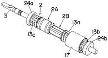
도 1은 본 발명의 하나의 실시형태에 의한 왕복 직선구동 및 롤링 구동이 가 능한 액츄에이터의 구성을 나타내는 측부 단면도이다.1 is a side cross-sectional view showing the configuration of an actuator capable of reciprocating linear drive and rolling drive according to an embodiment of the present invention.
도 2A는 도 1에 나타내는 액츄에이터의 외관구성을 나타내는 사시도이다.FIG. 2A is a perspective view showing an appearance configuration of the actuator shown in FIG. 1. FIG.
도 2B는 실드 케이스(shield case)를 제거한 상태에서의 내부구성을 나타내는 사시도이다.2B is a perspective view showing the internal structure in a state where a shield case is removed.
도 3은 도 1에 나타내는 액츄에이터의 분해 사시도이다.3 is an exploded perspective view of the actuator shown in FIG. 1.
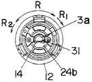
도 4는 도 1에 나타내는 액츄에이터의 후단부에 설치된 샤프트의 회전각도를 규제하기 위한 구조를 나타내는 도면이다.4 is a view showing a structure for regulating the rotation angle of a shaft provided at the rear end of the actuator shown in FIG. 1.
도 5A는 상기 실시형태에서의 제1 가동자를 구성하는 제1 영구자석 및 제1 요크를 샤프트에 끼워 맞춰 고정하는 구조의 변형예를 나타내는 사시도이다.FIG. 5A is a perspective view showing a modification of the structure in which the first permanent magnet and the first yoke constituting the first mover in the above embodiment are fitted to and fixed to a shaft. FIG.
도 5B는 상기 제1 요크의 형상을 나타내는 정면도이다.5B is a front view illustrating the shape of the first yoke.
도 6은 상기 변형예에서의 용수철 수용부재와 상기 제1 요크와의 결합상태를 나타내는 사시도이다.Fig. 6 is a perspective view showing a coupling state between the spring receiving member and the first yoke in the modification.
도 7은 상기 액츄에이터의 제2 가동자를 구성하는 샤프트에 제2 요크 및 용수철 수용부재를 조립한 상태를 나타내는 사시도이다.It is a perspective view which shows the state which assembled the 2nd yoke and the spring receiving member to the shaft which comprises the 2nd movable body of the said actuator.
도 8A는 상기 액츄에이터의 제2 가동자와 제2 고정자의 대향부분의 구성을 나타내는 측부 단면도이다.8A is a side sectional view showing a configuration of opposing portions of a second mover and a second stator of the actuator.
도 8B는 상기 제2 가동자와 제2 고정자의 대향부분의 구성을 나타내는 배면도이다.8B is a rear view showing the configuration of opposing portions of the second mover and the second stator.
도 8C는 상기 제2 가동자와 제2 고정자의 대향부분의 구성을 나타내는 정면도이다.8C is a front view illustrating the configuration of opposing portions of the second mover and the second stator.
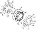
도 9는 상기 액츄에이터의 제2 고정자를 구성하는 제2 보빈(bobbin)과 제2 고정요크 구성을 나타내는 분해 사시도이다.FIG. 9 is an exploded perspective view showing a second bobbin and a second fixed yoke configuration constituting the second stator of the actuator. FIG.
도 10A는 상기 액츄에이터의 실드 케이스와 제2 고정자의 구성을 나타내는 분해 사시도이다.Fig. 10A is an exploded perspective view showing the configuration of the shield case and the second stator of the actuator.
도 10B는 상기 실드 케이스의 구성을 나타내는 정면 단면도이다.10B is a front sectional view showing the structure of the shield case.
도 11은 상기 용수철 수용부재에 용수철부재의 일단을 결합시키는 상태를 나타내는 측면도이다.11 is a side view illustrating a state in which one end of the spring member is coupled to the spring receiving member.
도 12A∼12D는 각각 상기 액츄에이터의 흡진추(吸振錘)의 구성을 나타내는 정면도, 측면 단면도, 배면도 및 사시도이다.12A to 12D are front views, side cross-sectional views, rear views, and perspective views each illustrating a configuration of a suction weight of the actuator.
도 13은, 액츄에이터에서 전압을 일정하게 한 경우에서의 교번전류의 주파수와 각 가동자의 진폭의 관계 및 그 경우에서의 주파수와 전류의 관계를 나타내는 그래프이다.Fig. 13 is a graph showing the relationship between the frequency of the alternating current and the amplitude of each mover when the voltage is constant in the actuator and the relationship between the frequency and the current in that case.
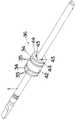
도 14는 본 발명의 하나의 실시형태에 의한 왕복 직선구동 및 롤링 구동이 가능한 액츄에이터를 사용한 전동칫솔의 구성을 나타내는 단면도이다.It is sectional drawing which shows the structure of the electric toothbrush using the actuator which can perform reciprocation linear drive and rolling drive by one Embodiment of this invention.
도 15는 종래의 진동형 리니어 액츄에이터(참고예)의 구성을 나타내는 단면도이다.Fig. 15 is a cross-sectional view showing the structure of a conventional vibration linear actuator (reference example).
발명을 실시하기 위한 최선의 형태Best Mode for Carrying Out the Invention
본 발명의 하나의 실시형태에 의한 왕복 직선구동 및 롤링 구동이 가능한 액츄에이터 및 그것을 사용한 전동칫솔에 대하여, 도면을 참조하면서 상세하게 설명 한다.An actuator capable of reciprocating linear drive and rolling drive and an electric toothbrush using the same according to one embodiment of the present invention will be described in detail with reference to the drawings.
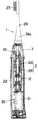
먼저, 전동칫솔의 액츄에이터로서 바람직한 본 실시형태에 의한 왕복 직선구동 및 롤링 구동이 가능한 액츄에이터에 대하여 설명한다. 도 1은 본 실시형태에 의한 왕복 직선구동 및 롤링 구동이 가능한 액츄에이터(2)의 구성을 나타내는 측부 단면도이다. 도 2A는 액츄에이터(2)의 외관구성을 나타내는 사시도이며, 도 2B는 실드 케이스(12)를 제거한 내부구성을 나타내는 사시도이다. 도 3은 액츄에이터(2)의 분해 사시도이다. 도 4는 액츄에이터(2)의 후단부에 설치된 샤프트의 회전각도를 규제하기 위한 구조를 나타내는 도면이다.First, the actuator which can perform the reciprocation linear drive and rolling drive by this embodiment which are preferable as an actuator of an electric toothbrush is demonstrated. 1 is a side sectional view showing the configuration of an
액츄에이터(2)는 샤프트(3)를 그 축방향으로 왕복 직선구동시키는 왕복 직선구동부(2A)와, 샤프트(3)를 그 축주위로 소정 범위에서 왕복 회전구동(롤링 구동)시키는 롤링 구동부(2B)를 구비하고 있다.The
실드 케이스(12)는 대략 원통형상이며, 그 전후의 개구부에 각각 씰(seal)부재(71 및 72)가 끼워 맞춰 고정되어 있다. 또한, 각 씰부재(71 및 72)에는, 각각 샤프트(3)를 화살표 L로 표시하는 바와 같이, 그 축방향으로 왕복 직선이동가능하게 축지지함과 아울러, 화살표 R로 표시하는 바와 같이, 그 축주위로 소정 범위에서 왕복 회전이 가능하도록 축지지하는 베어링(24a 및 24b)이 설치되어 있다. 그리고, 실드 케이스(12) 내에는, 샤프트(3)를 그 축방향으로 왕복 직선구동시키기 위한 왕복 직선구동부(2A)와, 샤프트(3)의 축주위로 롤링 구동시키기 위한 롤링 구동부(2B)가 내장되어 있다.The
먼저, 샤프트(3)를 화살표 L로 표시하는 축방향으로 왕복 직선구동시키기 위 한 왕복 직선구동부(2A)에 대하여 설명한다. 이 왕복 직선구동부(2A)는 제1 가동자(36)와 통형상을 한 제1 고정자(40)를 구비한다.First, the reciprocating
제1 고정자(40)는 대략 원통형상이며, 실드 케이스(12)의 내주면에 배치되어 있다. 제1 고정자(40)는 제1 보빈(38)에 전선을 감아서 형성된 제1 코일(37)과, 제1 보빈(38)의 양측에 설치된 고리형상(環狀)의 제1 고정요크(39)로 구성되어 있다.The
제1 가동자(36)는 샤프트(3), 제1 영구자석(34), 제1 요크(35), 간격대(spacer, 41) 및 철심(鐵心, 42) 등으로 구성되어 있다. 일반적으로, 샤프트(3)를 비자성체로 함으로써, 샤프트(3)를 통한 자속(磁束)의 누설이 없어져, 출력 손실을 줄일 수 있다. 그러나, 비자성재료는 일반적으로 고가이다. 또한, 저렴한 비자성재료의 강도는 낮다. 그 때문에, 샤프트(3)의 강도를 유지하면서, 비용을 줄이기 위하여, 본 실시형태에서는, 샤프트(3)는 자성재료로 형성되어 있다. 그리고, 샤프트(3)에 간격대(41)을 끼워 맞춰 고정하고, 또한, 간격대(41)를 통하여 소정의 간격을 두고 배치된 고리형상 또는 원통형상의 두 개의 제1 영구자석(34)과, 각각 제1 영구자석(34)의 양 단면에 각각 인접하도록 배치된 자성체로 형성된 네 개의 고리형상 또는 원통형상의 제1 요크(35)가 끼워 맞춰 고정되어 있다. 또한, 간격대(41)의 외주면에는, 철심(42)이 끼워 맞춰 고정되어 있다.The
한편, 각 도면에 도시하는 바와 같이, 제1 영구자석(34)의 두께, 즉, 샤프트(3)의 축방향의 길이가 제1 영구자석(34)의 샤프트(3)의 축에 직교하는 방향의 치수(예컨대, 직경)보다 짧으므로, 이하의 설명에서는 「고리형상」이라고 칭한다. 그러나, 본 발명에 의한 액츄에이터에서 사용되는 제1 영구자석(34)은 고리형상에 한정되는 것은 아니며, 샤프트(3)의 축방향의 길이가 샤프트(3)의 축에 직교하는 방향의 치수와 동일 또는 그보다 긴 원통형상이라도 좋다.On the other hand, as shown in each drawing, the thickness of the first
제1 영구자석(34)은 각각 그 두께방향으로 착자되어 있어, 샤프트(3)의 축방향에서의 양 단면의 극성이 각각 다르도록 설정되어 있다. 또한, 두 개의 제1 영구자석(34)은 서로 대향하는 면의 극성이 같아지도록, 샤프트(3)에 고정되어 있다. 예컨대, 좌측의 제1 영구자석(34L)의 좌측 단면의 극성을 S극이라고 하면, 그 제1 영구자석(34L)의 우측 단면의 극성이 N극, 우측의 제1 영구자석(34R)의 좌측 단면의 극성이 N극, 제1 영구자석(34R)의 우측 단면의 극성이 S극으로 된다. 반대의 경우도 마찬가지이다. 이와 같이, 샤프트(3)에 두 개의 제1 영구자석(34)을 그 축방향으로 병설함으로써, 큰 자속을 발생시킬 수 있다.The first
샤프트(3)에 제1 영구자석(34) 등을 끼워 맞춰 고정시켜서 구성된 제1 가동자(36)는 실드 케이스(12)에 고정된 제1 고정자(40)의 내주면에 대하여 소정의 간격을 갖도록, 실드 케이스(12)에 삽입되어 있다. 샤프트(3)에 끼워 맞춰 고정된 두 개의 제1 영구자석(34)의 간격은 제1 고정자(40)의 두 개의 제1 고정요크(39)의 간격보다 좁아지도록 설정되어 있다. 또한, 제1 가동자(36)가 화살표 L로 표시하는 샤프트(3)의 축방향으로 왕복 직선구동되지 않는 상태에 있어서, 두 개의 제1 고정요크(39) 사이의 중심위치와, 두 개의 제1 영구자석(34)의 사이의 중심위치가 대략 일치하도록 설정되어 있다. 한편, 반드시 이 구성예에 한정되는 것은 아니며, 두 개의 제1 영구자석(34)의 간격은 제1 고정자(40)의 두 개의 제1 고정요크 (39)의 간격과 같거나 또는 그보다 넓어도 좋다.The
여기에서, 제1 영구자석(34) 및 제1 요크(35)를 샤프트(3)에 끼워 맞춰 고정하는 구조의 변형예를 도 5A 및 도 5B에 도시한다. 상기 구성예에서는, 자성재료로 형성된 샤프트(3)에 간격대(41)을 끼워맞추고, 또한 간격대(41)에 제1 영구자석(34) 및 제1 요크(35)를 끼워 맞춰 고정하고 있다. 한편, 도 5A 및 도 5B에 나타내는 변형예에서는, 간격대(41) 대신에, 제1 요크(35)의 내주부에 복수(예컨대, 네 개)의 돌기(44) 및 각 돌기(44) 사이의 간격(43)을 형성하고, 돌기(44)를 샤프트(3)의 외주면에 접촉시킴으로써, 제1 요크(35)를 샤프트(3)에 끼워 맞춰 고정시키고 있다. 도시하지 않고 있지만, 각 영구자석(34)에 대하여도 마찬가지이다. 그 결과, 샤프트(3)의 비용 줄임 및 강도를 확보하기 위하여 자성재료에 의해 샤프트(3)를 형성하였음에도 불구하고, 영구자석(34)에 의한 자속이 샤프트(3)측으로 대부분 통과하지 않아, 대부분을 제1 고정요크(39)측으로 통과시킬 수 있어, 제1 영구자석(34)에 의한 자속을 유효하게 이용할 수 있다.Here, the modification of the structure which fits and fixes the 1st
다음에, 화살표 R로 표시하는 바와 같이, 상기 샤프트(3)를 축주위로 롤링 구동시키기 위한 롤링 구동부(2B)에 대하여 설명한다. 이 롤링 구동부(2B)는 제2 가동자(6)와, 통형상을 한 제2 고정자(10)를 구비한다.Next, as shown by arrow R, the rolling
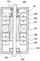
제2 가동자(6)는 샤프트(3)와, 샤프트(3)에 압입(壓入) 고정된 제2 요크(5)와, 제2 요크(5)에 고정된 평판형상의 제2 영구자석(4) 등으로 구성되어 있다. 제2 고정자(10)는 제2 보빈(8)과, 제2 보빈(8)에 전선을 감아서 구성된 제2 코일(7)과, 샤프트(3)의 축방향에서 제2 보빈(8)의 양측에 배치된 제2 고정요크(9) 등으로 구성되어 있다. 제2 고정자(10)는 대략 통형상으로 형성되어, 실드 케이스(12)의 내주면에 고정되어 있다. 제2 가동자(6)는 샤프트(3)가 베어링(24a 및 24b)에 축지지됨으로써, 제2 가동자(6)의 샤프트(3)의 축에 직교하는 방향의 최외주부가 제2 고정자(10)의 최내주부에 대하여 소정의 간격을 유지하도록 지지된다. 이와 같이, 제2 고정자(10)의 안쪽에 제2 가동자(6)를 소정의 간격을 두어 회전이 가능하게 삽입하여 통과시킴으로써, 액츄에이터(2)의 롤링 구동용의 자기회로가 구성된다. 한편, 제2 고정요크(9)는 반드시 샤프트(3)의 축방향에서의 제2 보빈(8)의 양측에 설치할 필요는 없고, 한 쪽에만 설치하여 좋다.The
제2 가동자(6)는 도 1에 도시하는 바와 같이, 화살표 L로 표시하는 샤프트(3)의 축방향에서의 왕복 운동범위내에 있어서, 제2 영구자석(4)과 제2 고정요크(9)의 자극자(磁極子, 11)와의 간격을 일정하게 유지할 수 있는 길이 S2를 갖고 있다. 구체적으로는, 샤프트(3)의 축방향에 있어서, 제2 가동자(6)의 제2 영구자석(4)의 중간위치와 제2 보빈(8)의 양측에 설치된 두 개의 제2 고정요크(9)의 중간위치가 대략 일치한 상태에서, 제2 영구자석(4)의 길이 S2가 제2 고정요크(9) 사이의 거리 S1보다 길어지도록(S1<S2) 설정되어 있다. 그 때문에, 제2 가동자(6)는 샤프트(3)의 축방향에서의 왕복 직선구동 가능범위에 있어서, 제2 영구자석(4)과 제2 고정요크(9)의 자극자(11)가 멀어지는 일 없어, 항상 일정한 간격을 유지할 수 있다. 그 결과, 화살표 R로 표시하는 샤프트(3)의 축주위의 제2 가동자(6)의 롤링 구동을 연속하여 행할 수 있다.As shown in FIG. 1, the
제2 요크(5)를 샤프트(3)에 압입 고정한 상태를 도 7에 도시한다. 또한, 제 2 가동자(6)와 제2 고정자(10)의 대향하는 부분, 즉, 구동력을 발생시키기 위한 주요부분의 구성을 도 8A∼도 8C에 도시한다. 각 도면으로부터 알 수 있는 바와 같이, 제2 요크(5)는 철 등의 자성재료에 의해 대략 통형상으로 형성되어 있고, 그 외주면에 적어도 한 개(도면에서는 네 개)의 홈(25)이 형성되어 있다. 홈(25)은 샤프트(3)의 축방향을 따라 형성되고, 저면이 평면으로 되도록 단면이 대략 ㄷ자 모양(채널형상)으로 형성되어 있다. 그리고, 홈(25)의 깊이와 제2 영구자석(4)의 판두께 및 홈(25)의 폭과 제2 영구자석(4)의 폭이 각각 거의 같아지도록 설정되어 있으므로, 도 8A∼도 8C에 도시하는 바와 같이, 홈(25)에 각각 평판형상의 제2 영구자석(4)이 거의 간격이 없이 끼워 설치된다. 그 결과, 평판형상의 제2 영구자석(4)의 외면(4a)과 제2 요크(5)의 원호형상의 외면(5a)이 원주방향으로 인접하게 배치된 상태로 된다.7 shows a state in which the
제2 영구자석(4)은 샤프트(3)의 축방향에 직교하는 방향의 외면(4a)의 극성과 내면(4b)의 극성이 각각 다르도록, 각각 두께방향으로 착자되어 있다. 또한, 각각 제2 영구자석(4)은 제2 요크(5)에 대하여 같은 방향으로, 예컨대, 네 개의 제2 영구자석(4)의 외면(4a)의 모두가 N극으로 되도록 설치되어 있다. 제2 영구자석(4)을 이렇게 요크(5)에 설치함으로써, 인접하는 두 개의 제2 영구자석(4)의 사이에 배치된 제2 요크(5)의 원호형상 외면(5a)은 모두 S극으로 된다. 반대의 경우도 마찬가지이다.The second
도 8A∼8C는 각각 제2 코일(7)에 전류를 공급하지 않는 초기상태를 나타내고 있다. 제2 코일(7)에 전류를 공급하지 않을 때는, 제2 영구자석(4)이 제2 고정요 크(9)에 미치는 자력과 용수철부재(13a, 13b 및 13c)의 용수철 힘이 균형이 잡히는 위치에서, 제2 가동자(6)가 정지하고 있다. 그리고, 제2 고정요크(9)에 설치된 각자극자(11a 및 11b)가 각각 제2 영구자석(4)과 대향하도록 위치하고 있다. 제2 코일(7)에 한 방향의 전류를 공급하면, 한 쪽의 제2 고정요크(9)의 자극자(11a)가 N극으로 되고, 다른 쪽의 제2 고정요크(9)의 자극자(11b)이 S극으로 된다. 그 때문에, 도 4에 도시하는 바와 같이, 제2 가동자(6)는 샤프트(3)의 축주위의 한 방향, 예컨대, 화살표 R1로 표시하는 방향으로 회동된다. 제2 코일(7)에 역방향의 전류를 공급하면, 한 쪽의 제2 고정요크(9)의 자극자(11a)가 S극으로 되고, 다른 쪽의 제2 고정요크(9)의 자극자(11b)가 N극으로 된다. 그 때문에, 제2 가동자(6)는 샤프트(3)의 축주위의 다른 방향, 예컨대 화살표 R2로 표시하는 방향으로 회전된다. 따라서, 제2 코일(7)에 교번전류를 공급함으로써, 제2 가동자(6)를 화살표 R로 표시하는 샤프트(3)의 축주위로 소정 각도범위에서 롤링 구동시킬 수 있다.8A to 8C respectively show an initial state in which no current is supplied to the
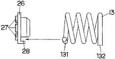
앞족의 베어링(24a)의 후면, 제1 가동자(36)의 앞쪽 단면, 제2 가동자(6)의 뒤쪽 단면, 및 뒤쪽의 베어링(24b)의 전면에 대향하도록, 각각 비자성재료로 형성된 용수철 수용부재(26)가 샤프트(3)에 끼워맞추어져 있다. 또한, 제2 가동자(6)와 뒤쪽의 베어링(24b)의 사이에는, 대략 원통형상의 흡진추(17)가 샤프트(3)에 대하여 비교적 큰 유격을 갖게 하여 끼워 설치되어 있다. 그리고, 코일 용수철(13a 및 13b)이 각각 용수철 수용부재(26)와 흡진추(17)의 사이에 설치되고, 또한 코일 용수철(13c)이 제1 가동자(36)와 앞쪽의 베어링(24a)의 각 용수철 수용부재(26)의 사이에 설치되어 있다.Each formed of a non-magnetic material so as to face the rear face of the front foot bearing 24a, the front end face of the
용수철부재(13a, 13b 및 13c)의 구성 및 용수철 수용부재(26)의 구성을 도 11에 도시한다. 각 용수철부재(13a, 13b 및 13c)는 각각 대략 동일형상이며, 두 개의 팔(131 및 132)를 갖는 비틀림 코일 용수철(13)로 구성되어 있다. 또한, 각 용수철 수용부재(26)에는, 각 용수철부재(13a, 13b 및 13c)의 팔(131 또는 132)을 끼워 지지하여, 용수철부재(13a, 13b 및 13c)의 회전을 저지하기 위한 걸림부(28)가 형성되어 있다.The structure of the
네 개의 용수철 수용부재(26) 중, 두 개는 실드 케이스(12)의 베어링(24a 및 24b)에 대하여, 샤프트(3)의 축주위로 회전이 불가능하게 고정되어 있어, 제1 고정자(40) 및 제2 고정자(10)에 대하여 상대적으로 작용하지 않는다. 또한, 나머지 두 개의 용수철 수용부재(26)는 샤프트(3)와 함께 그 축방향으로 회전하는 제1 가동자(36) 및 제2 가동자(6)에 고정되어, 제1 가동자(36) 및 제2 가동자(6)와 함께 변위한다. 그 때문에, 제2 가동자(6)가 샤프트(3)의 축주위로 회전됨으로써, 각 용수철(13a, 13b 및 13c)이 각각 감김 조임 방향 또는 느슨한 방향으로 회전되어, 각 용수철(13a, 13b 및 13c)에 탄성 반력(反力)이 축적된다. 그 결과, 샤프트(3)의 축주위의 회전가능범위가 제한된다.Of the four
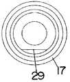
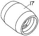
또한, 흡진추(17)의 구성을 도 12A∼12D에 도시한다. 흡진추(17)에도, 용수철부재(13a 및 13b)의 팔(131 또는 132)을 걸어서 회전을 저지하기 위한 걸림부(29 및 30)가 형성되어 있다. 이와 같이 세 개의 용수철 부재(13a, 13b 및 13c)의 각 팔(131 및 132)을, 각각 용수철 수용부재(26) 및 흡진추(17)의 각 걸림부(28, 29 및 30)로 회전정지를 고정함으로써, 제1 가동자(36)를 화살표 L로 표시하는 바와 같이, 샤프트(3)의 축방향으로 왕복 직선구동이 가능한 상태로 지지함과 아울러, 화살표 R로 표시하는 바와 같이, 제2 가동자(6)를 샤프트(3)의 축주위로 소정 범위내에서 왕복 회전이 가능한 상태로 지지한다. 흡진추(17)의 중심위치는 제2 가동자(6)의 회전축과 같은 축상에 배치되어 있으므로, 제2 가동자(6)가 샤프트(3)의 축주위로 회전될 때에, 제2 가동자(6)와 흡진추(17)가 샤프트(3)의 축주위로 각각 반대위상으로 회전구동된다.In addition, the structure of the
본 실시형태에 의한 액츄에이터(2)에서는, 제1 코일(37) 및 제2 코일에 대하여 선택적으로 교번전류를 공급함으로써, 샤프트(3)를 그 축방향으로 왕복 직선구동 또는 그 축주위로 롤링 구동할 수 있다. 또한, 제1 코일(37) 및 제2 코일에 대하여 동시에 교번전류를 공급함으로써, 샤프트(3)를 그 축방향으로 왕복 직선구동하면서, 동시에 그 축주위로 롤링 구동할 수 있다.In the
샤프트(3)를 화살표 L로 표시하는 그 축방향으로 왕복 직선구동시키는 경우, 제1 가동자(36)와 용수철부재(13a, 13b 및 13c)로, 제1 가동자(36)의 왕복 직선운동의 진동계(振動系)를 구성한다. 즉, 제1 가동자(36)의 왕복 직선운동에 따라 세 개의 용수철부재(13a, 13b 및 13c)가 신장 및 압축되어, 압축력 및 인장력을 제1 가동자(36)에 부여한다.When the
제1 코일(37)에 전류가 흐르지 않는 상태에서는, 제1 영구자석(34)이 제1 고정요크(39)에 미치는 자력과 용수철부재(13a, 13b 및 13c)의 밀어붙이는 힘이 균형이 잡히는 위치에서 제1 가동자(36)가 정지하고, 제1 가동자(36)의 두 개의 제1 영구자석(34)의 외측면은 각각 제1 고정자(40)의 두 개의 제1 고정요크(39)의 내측면 과 대향한다.In a state in which no current flows in the first coil 37, the magnetic force applied by the first
제1 코일(37)에 한 방향 전류가 흐르면, 제1 가동자(36)가 한 방향으로 이동하고, 제1 코일(37)에 역방향전류가 흐르면, 제1 가동자(36)가 역방향으로 이동한다. 그 때문에, 제1 코일(37)에 교번전류를 흘려보냄으로써, 제1 가동자(36)를 샤프트(3)의 축방향으로 왕복 구동시킬 수 있다. 특히, 용수철부재(13a, 13b 및 13c)의 용수철 정수(定數) 및 제1 가동자(36)와 제2 가동자(6)의 총 질량으로 결정되는 공진주파수 부근의 교번전류를 제1 코일(37)에 흘려보냄으로써, 제1 가동자(36)의 왕복 직선운동(왕복 진동)을 공진상태에 가까운 상태로 할 수 있고, 이에 의해 제1 가동자(36)의 이동량(진폭량)을 크게 할 수 있다.When the current flows in one direction in the first coil 37, the
한편, 화살표 R로 표시하는 바와 같이, 샤프트(3)를 그 축주위로 왕복 회전구동시키는 경우, 제2 가동자(6)와 용수철부재(13a, 13b 및 13c)로, 제2 가동자(6)의 롤링 구동의 진동계를 구성한다. 즉, 제2 가동자(6)의 롤링 구동에 따라 세 개의 용수철부재(13a, 13b 및 13c)는 샤프트(3)의 축주위에서의 제2 가동자(6)의 롤링 구동에 따라, 감김 조임 방향 및 느슨한 방향으로 비틀어진다. 그 결과, 제2 가동자(6)의 샤프트(3)의 축주위에 회전을 방해하는 방향으로 밀어붙이는 힘을 부여한다. 이 용수철부재(13a, 13b 및 13c)의 용수철 정수와 제1 가동자(36)와 제2 가동자(6)의 총 질량으로 결정되는 공진주파수 부근의 전류를 제2 코일(7)에 공급함으로써, 제2 가동자(6)의 진동량(진폭량)을 크게 할 수 있다.On the other hand, as indicated by the arrow R, when the
제2 코일(7)에 한 방향의 전류를 공급하면, 제2 영구자석(4)은 한 쪽의 제2 고정요크(9)의 자극자(11a)로부터는 자기반발력을 받고, 동시에 다른 쪽의 자극자 (11b)로부터는 자기흡인력을 받는다. 그 때문에, 제2 가동자(6)는 샤프트(3)의 축주위의 한 방향(예컨대, 화살표 R1로 표시하는 방향)으로 큰 힘으로 회전구동된다. 제2 코일(7)에 역방향의 전류를 공급하면, 제2 영구자석(4)은 한 쪽의 제2 고정요크(9)의 자극자(11a)로부터는 자기흡인력을 받고, 동시에 다른 쪽의 자극자(11b)로부터는 자기반발력을 받으므로, 샤프트(3)의 축주위의 다른 방향(예컨대, 화살표 R2로 표시하는 방향)으로 큰 힘으로 회전구동된다. 그 때문에, 제2 코일(7)에 교번전류를 공급함으로써, 제2 가동자(6)를 샤프트(3)의 축주위로 롤링 구동시킬 수 있다.When the current in one direction is supplied to the
또한, 극성이 다른 제2 영구자석(4)의 외면(4a)과 제2 요크(5)의 외면(5a)이 제2 가동자(6)의 원주방향으로 인접하여 배치되어 있기 때문에, 자극자(11a 및 11b)와 제2 요크(5)의 외면(5a)의 사이에서도 가동자(6)를 회전시키는 구동력이 발생된다. 또한, 제2 영구자석(4)의 외면(4a)은 평탄하기 때문에, 자극자(11)와의 대향면적을 크게 확보할 수 있다. 한편, 제2 요크(5)의 외면(5a)은 원호형상이기 때문에, 자극자(11)와의 대향면적을 크게 확보하면서, 자극자(11)와의 간격을 작게 할 수 있다. 그 때문에, 제2 가동자(6)를 샤프트(3)의 축주위로 회전구동시키는 구동력을 더욱 크게 할 수 있어, 제2 가동자(6)는 회전 초기에 있어서의 구동력이 커지므로, 롤링 구동을 원활하게 개시시키는 것이 가능하게 된다.Further, since the
또한, 제1 고정자(40), 제2 고정자(10) 및 실드 케이스(12)를 고정부로 하여, 제1 가동자(36)와 제2 가동자(6)의 총 질량 및 흡진추(17)의 질량의 2질점계(質點系) 진동모델로서 취급할 수 있다. 흡진추(17)는 왕복 직선구동의 진동계의 것과 롤링 구동의 진동계의 것을 겸용하고 있다. 그리고, 제1 가동자(36)에 의한 왕복 직선구동과 제2 가동자(6)의 롤링 구동이 동시에 행하여지는 경우, 흡진추(17)는 샤프트(3)의 축방향에서 제1 가동자(36)와는 반대위상으로 왕복 직선구동되고, 또한, 샤프트(3)의 축주위에서 제2 가동자(6)와는 반대위상으로 회전구동되도록 되어 있다. 이 경우, 제1 가동자(36) 또는 제2 가동자(6)와 흡진추(17)가 같은 위상으로 구동하는 제1차(次, 저차측(低次側))의 진동 모드와, 제1 가동자(36) 또는 제2 가동자(6)와 흡진추(17)가 반대 위상으로 구동하는 제2차(고차측(高次側))의 진동모드가 있다. 이 제2차의 고유진동수 근방의 주파수를 갖는 전류를 제1 코일(37) 및/또는 제2 코일(7)에 공급함으로써 제1 가동자(36) 또는 제2 가동자(6)를 축방향의 왕복 직선구동 및/또는 축주위의 롤링 구동하는 경우, 반대 위상의 구동을 행하는 흡진추(17)가 제1 가동자(36) 및 제2 가동자(6)의 관성력을 없애며, 반대로, 흡진추(17)의 관성력을 제1 가동자(36) 및 제2 가동자(6)가 없앤다. 그것에 의해, 실드 케이스(12)측으로 전달되는 진동을 감소시킬 수 있다. 또한, 흡진추(17)와 샤프트(3)의 사이에, 샤프트(3)의 축방향과 직교하는 방향으로 간격(18)이 형성되어 있다. 이 간격(18)은 공기 틈(air gap)이며, 흡진추(17)를 저항 없이 원활한 동작으로 샤프트(3)의 축주위로 회전구동시키는 작용을 한다. 한편, 베어링 등을 개재시켜도 좋지만, 비용을 낮게 억제하기 위해서는 간격(18)을 형성하는 쪽이 바람직하다.In addition, the total mass and the
또한, 제2 가동자(6)의 롤링 구동시에 흡진추(17)의 관성모멘트가 제1 가동자(36) 및 제2 가동자(6)의 관성모멘트보다 커지도록 설정되어 있다. 본 실시형태 에서는, 흡진추(17)의 중량을 조절함으로써, 흡진추(17)의 관성모멘트가 제1 가동자(36) 및 제2 가동자(6)의 관성모멘트보다 커지도록 설정하여도 좋다. 흡진추(17)의 관성모멘트를 크게 함으로써, 제1 가동자(36) 및 제2 가동자(6)의 왕복 직선구동 방향 또는 롤링 구동 방향의 보조력이 증대하여, 액츄에이터(2)의 출력을 더욱 크게 할 수 있다.Moreover, the moment of inertia of the
또한, 제2 가동자(6)의 샤프트(3)의 축주위에서의 회전동작에 수반하여 각 용수철부재(13a, 13b 및 13c)에 탄성력이 축적된다. 그 결과, 제2 가동자(6)의 샤프트(3)의 축주위에서의 회전이 가능한 각도범위가 규제되어, 샤프트(3)의 롤링 각도가 결정된다.In addition, an elastic force is accumulated in each of the
그런데, 상기 용수철부재(13a, 13b 및 13c)만으로 제2 가동자(6)의 회전을 규제하는 구조에서는, 외부로부터 제2 가동자(6)를 샤프트(3)의 축주위로 허용 범위이상으로 회전시키는 힘이 가하여졌을 때에는 제2 가동자(6)가 허용 범위를 넘어서 회전할 가능성이 있어, 액츄에이터(2)의 구동특성에 악영향을 끼칠 우려가 있다. 그래서, 외부로부터 제2 가동자(6)에 대하여 샤프트(3)의 축주위로 허용 범위이상의 회전력이 가하여졌을 때에, 제2 가동자(6)의 회전을 기계적으로 저지하기 위하여, 도 4에 도시하는 바와 같은 샤프트(3)의 회전규제 구조가 설치되어 있다.By the way, in the structure which restricts rotation of the
샤프트(3)의 후단부(3a)는 단면이 대략 D자 모양으로 형성되어 있다. 한편, 뒤쪽의 씰부재(72)에는, 샤프트(3)의 후단부(3a)가 끼워 맞추어져, 샤프트(3)의 축주위의 회전을 규제하기 위한 대략 부채형의 끼워맞춤 구멍(14)이 형성되어 있다. 샤프트(3)의 후단부(3a)가 끼워맞춤 구멍(14)에 끼워 맞추어짐으로써, 샤프트(3)의 축주위의 회전각도가 일정한 범위로 규제된다. 끼워맞춤 구멍(14)에는 산형상(山形狀) 테이퍼(taper)면(31)이 형성되어 있어, 제2 가동자(6)가 진폭의 중립위치에 있을 때는, 샤프트(3)의 후단부(3a)의 대략 D자 모양 단면의 평면부는 산형상 테이퍼면(31)의 경사면에 접촉하지 않아, 가동자(6)는 샤프트(3)의 축주위로 왕복 회전이 가능하다. 가동자(6)가 샤프트(3)의 축주위의 화살표 R1으로 표시하는 방향으로 허용 범위를 초과하여 회전하면, 샤프트(3)의 후단부(3a)의 대략 D자 모양 단면의 평면부는 산형상 테이퍼면(31)의 경사면에 접촉하여, 그 이상의 회전이 규제된다. 화살표 R2로 표시하는 역방으로에 회전하는 경우도 마찬가지이다. 이에 의해, 제2 가동자(6)의 롤링 각도 이상의 회전이 기계적으로 규제되게 되어, 외적 부가하중이나 충격하중 등에 대하여 액츄에이터(2)의 신뢰성을 확보할 수 있다.The
한편, 샤프트(3)의 후단부(3a)는 샤프트(3)에 제2 요크(5)을 압입 고정할 때의 기준면으로서도 사용할 수 있다. 구체적으로는, 제2 요크(5)의 ㄷ자 모양홈(25)의 평탄한 저면(25a, 도 4 참조)과 샤프트(3)의 후단부(3a)의 대략 D자 모양 단면의 평면부가 대략 평행하게 되도록 제2 요크(5)을 압입시키므로, 샤프트(3)에 대한 제2 요크(5)의 정규적인 조립각도를 용이하게 결정할 수 있다.On the other hand, the
또한, 도 5에 도시하는 변형예에 있어서는, 도 6에 도시하는 바와 같이, 용수철 수용부재(26)의 용수철부재(13a, 13b 또는 13c)와는 접촉하지 않는 측의 단면에 복수(예컨대, 네 개)의 결합 돌기부(26a)를 형성하여, 제1 요크(35)에 형성된 간격(43)에 결합시켜도 좋다. 이러한 구성에 의해, 용수철 수용부재(26)의 제1 요크(35)에 대한 샤프트(3)의 중심축 주위의 회전이 규제된다.In addition, in the modification shown in FIG. 5, as shown in FIG. 6, a plurality (for example, four pieces) are provided in the cross section of the side which does not contact the
또한, 도 7에 도시하는 바와 같이, 용수철 수용부재(26)의 한 면에는, 복수의 돌기(27)가 설치되어 있어, 돌기(27)를 제2 요크(5)의 홈(25)의 길이방향의 단부에 삽입시킴으로써, 용수철 수용부재(26)가 제2 요크(5)에 대하여 회전이 불가능하게 고정된다.In addition, as shown in FIG. 7, a plurality of
도 8B 및 도 8C에 도시하는 바와 같이, 각각 제2 고정요크(9)의 내주부에는, 제2 가동자(6)의 극(제2 영구자석(4)의 외면(4a) 및 요크(5)의 외면(5a))에 대향하도록, 소정수 이하(도면에서는, 네 곳)의 자극자(11)가 설치되어 있다. 도 9에 도시하는 바와 같이, 제2 고정요크(9)의 인접하는 자극자(11)의 사이에는, 각각 절결부(117)가 형성되어 있다. 이와 같이, 자극자(11)의 사이에 절결부(117)를 설치함으로써, 샤프트(3)를 철 등의 자성재료로 형성한 경우에 있어서, 샤프트(3)에 대한 자속누설을 적게 할 수 있어, 제2 영구자석(4)에 의한 자속을 제2 고정요크(9)측에서 유효하게 사용할 수 있다. 한편, 자극자(11)의 수는 적어도 한 개 이상이면 좋지만, 출력을 높이기 위해서는, 자극자(11)의 수를 영구자석(4)의 수(네 개)와 같은 수까지 늘릴 수 있다.As shown in FIG. 8B and FIG. 8C, the poles (the
도 8A에 도시하는 바와 같이, 샤프트(3)의 축방향에 있어서, 제2 고정요크(9)를 제2 보빈(8)의 축방향의 양측에 설치하는 경우, 도 8B 및 도 8C에 도시하는 바와 같이, 한 쪽의 제2 고정요크(9)의 자극자(11a)의 위치와, 다른 쪽의 제2 고정요크(9)의 자극자(11b)의 위치가 제2 가동자(6)의 샤프트(3)의 축주위에서 일치하지 않도록, 각각 제2 고정요크(9)를 배치하고 있다. 또한, 제2 코일(7)에 전류를 공급하지 않는 제2 가동자(6)의 초기위치에서는, 한 쪽의 제2 고정요크(9)의 자극 자(11a)가 제2 영구자석(4)의 샤프트(3)의 축주위에서의 일단부와 제2 요크(5)의 한 쪽의 접점(15a)에 대향하도록 위치하고, 다른 쪽의 제2 고정요크(9)의 자극자(11b)가, 같은 제2 영구자석(4)의 타단부와 제2 요크(5)와 다른 쪽의 접점(15b)에 대향하게 위치하도록 설정되어 있다. 이에 의해, 동일한 제2 영구자석(4)에 대한 한 쪽의 제2 고정요크(9)의 자극자(11a)와의 간격과, 다른 쪽의 제2 고정요크(9)의 자극자(11b)와의 간격이 대략 같아지게 되어, 제2 가동자(6)의 롤링 구동이 효율적으로 행하여진다.As shown in FIG. 8A, in the axial direction of the
또한, 도 9에 도시하는 바와 같이, 샤프트(3)의 축방향에서의 제2 보빈(8)의 양 단면에는, 제2 고정요크(9)를 제2 보빈(8)에 대하여 축주위에 위치 결정하기 위한 고정요크 위치결정부(16)가 각각 설치되어 있다. 도 9에 도시하는 예에서는, 제2 보빈(8)의 단면에, 소정 간격으로 네 곳의 대략 원호형상을 한 돌기(凸) 리브(rib)모양의 고정요크 위치결정부(16)가 돌출 설치되어 있다. 한편, 제2 고정요크(9)에는, 전술한 바와 같이, 인접하는 자극자(11)의 사이에 절결부(117)가 형성되어 있다. 고정요크 위치결정부(16)가 각각 제2 고정요크(9)의 절결부(117)에 끼워 맞추어지도록, 두 개의 제2 고정요크(9)를 샤프트(3)의 축방향을 따라 제2 보빈(8)의 양 단면에 설치함으로써, 샤프트(3)의 축주위에서의 두 개의 제2 고정요크(9)의 상대적인 위치가 고정된다.In addition, as shown in FIG. 9, the second fixed
또한, 도 10A에 도시하는 바와 같이, 대략 원통형상의 실드 케이스(12)에는, 예컨대, 프레스 가공에 의해 내주면측으로 돌출된 회전규제부(20a)가 형성되어 있다. 이에 따라, 제2 보빈(18) 및 제2 고정요크(9)의 외주부에는, 회전규제부(20a) 와 결합되는 결합 오목부(凹部, 19)가 형성되어 있다. 결합 오목부(19)와 회전규제부(20a)를 결합시키도록, 제2 고정자(10)를 실드 케이스(12)의 내주면에 끼워 맞추게 함으로써, 샤프트(3)의 축주위에서의 제2 고정요크(9)의 실드 케이스(12)에 대한 회전도 규제된다. 실드 케이스(12)에는, 마찬가지로 예컨대, 프레스 가공에 의해 내주면측으로 돌출된 복수의 스토퍼(stopper, 20b)가 형성되어 있다. 예컨대, 도 10A에 있어서, 실드 케이스(12)의 오른쪽의 개구부로부터, 제2 고정자(10)를 실드 케이스(12)의 내주면에 끼워 맞추어가면, 왼쪽의 제2 고정요크(9)가 스토퍼(20b)에 접촉하여, 그 위치에서, 샤프트(3)의 축방향의 이동이 규제된다. 이러한 구조에 의해, 실드 케이스(12)에 대한 제2 고정자(10)의 고정이 용이하게 된다. 한편, 제2 고정요크(9)의 외주부에 결합 돌기부를 형성하고, 실드 케이스(12)의 내주면측에 설치된 회전규제부(20a)로서, 타발가공(打拔加工)에 의해 오목홈을 형성하여도 같은 효과를 얻을 수 있다.In addition, as shown in FIG. 10A, the substantially
또한, 도 3에 도시하는 바와 같이, 왕복 직선구동부(2A)와 롤링 구동부(2B)의 사이에, 비자성재료로 형성된 통형상 또는 고리형상의 자기실드부재(magnetic shielding member, 50)를 설치하여도 좋다. 이에 의해, 공통되는 한 개의 샤프트(3)의 축방향으로 왕복 직선구동부(2A)와 롤링 구동부(2B)를 인접하여 설치한 경우라도, 왕복 직선구동부(2A)와 롤링 구동부(2B)로부터의 각 자속을, 자기실드부재(50)에 의해 차단할 수 있다. 또한, 자기실드부재(50)를 원통형상 또는 고리형상으로 하므로, 제1 영구자석(34) 및 제2 영구자석(4)에 의한 자속을 누설함이 없이 차단할 수 있다. 그 결과, 한 쪽의 왕복 직선구동부(2A) 또는 롤링 구동부(2B)에 서의 제1 영구자석(34) 또는 제2 영구자석(4)의 자력의 영향을 다른 쪽의 롤링 구동부(2B) 또는 왕복 직선구동부(2A)에 영향을 미치지 않도록 할 수 있고, 왕복 직선구동부(2A)에 의한 샤프트(3)의 축방향의 왕복 직선구동 및 롤링 구동부(2B)에 의한 샤프트(3)의 축주위의 롤링 구동의 두 개의 동작을 안정되게 얻을 수 있다.As shown in Fig. 3, a cylindrical or annular magnetic shielding
이와 같이, 본 실시형태에 의한 액츄에이터(2)에 의하면, 공통되는 한 개의 샤프트(3)의 축방향을 따라, 각각 다른 위치에 왕복 직선구동부(2A)와 롤링 구동부(2B)가 설치되므로, 샤프트(3)를 그 축방향의 왕복 직선운동과 축주위의 롤링 구동의 두 개의 동작을 동시에 행하는 것이 가능하게 된다.Thus, according to the
또한, 왕복 직선구동부(2A) 및 롤링 구동부(2B)를 구성하는 원통형상 또는 고리형상의 제1 영구자석(34) 및 평판형상의 제2 영구자석(4)을, 제1 고정자(40) 및 제2 고정자(10)측이 아니라, 제1 가동자(36) 및 제2 가동자(6)측에 설치하고 있다. 그 때문에, 원통형상 또는 고리형상의 제1 영구자석(34)인 경우, 종래와 같이 대경의 영구자석을 실드 케이스(12)의 내면에 배치하는 경우와 비교하여, 제1 영구자석(34)의 내경 및 외경이 작아져, 제1 영구자석(34)의 체적이 작게 된다. 그 결과, 왕복 직선구동부(2A)를 소형 경량화하는 것이 가능하게 됨과 아울러, 재료면에서의 제1 영구자석(34)의 비용을 줄이는 것이 가능하게 된다. 또한, 제1 영구자석(34)은 예컨대, 축방향으로 착자된 통형상의 영구자석을 둥글게 자르게 하거나, 또는 고리형상의 자성재료를 그 두께방향으로 착자함으로써 제조할 수 있으므로, 제1 영구자석(34)의 제조가 용이하게 되어, 제조면에서의 비용을 줄일 수 있다.The first
평판형상의 제2 영구자석(4)의 경우도 마찬가지로, 종래와 같이 대경의 영구 자석을 실드 케이스(12)의 내면에 배치하는 경우와 비교하여, 제2 영구자석(4)의 체적이 작게 된다. 그 결과, 롤링 구동부(2B)를 소형 경량화하는 것이 가능하게 됨과 아울러, 재료면에서의 제2 영구자석(4)의 비용을 줄이는 것이 가능하게 된다. 또한, 제2 영구자석(4)은 그 두께방향으로 착자되어 있으므로, 두께방향으로 착자된 큰 판형상의 영구자석을 직사각형으로 절단함으로써 제조할 수 있으므로, 제2 영구자석(4)의 제조가 용이하게 되어, 제조면에서의 비용을 줄일 수 있다. 이들의 각 효과를 종합함으로써, 액츄에이터(2)의 소형 경량화 및 비용의 대폭적인 줄임기 가능하게 된다.Similarly, in the case of the plate-shaped second
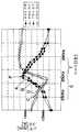
다음에, 본 실시형태에 의한 액츄에이터(2)에 있어서, 제1 코일(37) 또는 제2 코일(7)에 공급되는 교번전류의 전압을 일정하게 한 경우에서의 주파수와 제1 가동자(36) 또는 제2 가동자(6)의 진폭의 관계, 및 그 경우에서의 주파수와 전류의 관계에 대하여, 도 13에 도시하는 그래프를 참조하면서 설명한다.Next, in the
도 13에 있어서, 곡선 A 및 B는 각각 전압을 일정하게 한 경우에서의 주파수와 제1 가동자(36) 또는 제2 가동자(6)의 진폭의 관계를 나타내고, 곡선 C 및 D는 각각 주파수와 전류의 관계를 나타낸다. 도 13 중, ◆은 무부하시(無負荷時)에서의 진폭을, ●은 부하시에서의 진폭을, ◇은 무부하시에서의 전류값을, ○은 부하시에서의 전류값을 각각 나타낸다.In Fig. 13, curves A and B show the relationship between the frequency and the amplitude of the
전술한 바와 같이, 용수철부재(13a, 13b 및 13c)의 용수철 정수 및 제1 가동자(36) 및 제2 가동자(6)의 총 질량 등으로 결정되는 공진주파수(도 13에서 점 P로 표시함) 부근의 주파수를 갖는 교번전류를 제1 코일(37) 또는 제2 코일(7)에 공급 함으로써, 제1 가동자(36) 또는 제2 가동자(6)의 진동량(진폭량)을 크게 할 수 있다. 예컨대, 주파수가 250Hz 부근에서는, 제1 가동자(36) 또는 제2 가동자(6)의 진폭은 최대값 1.1mm을 나타낸다. 주파수가 230Hz 이상, 250Hz 이하의 범위 S 및 250Hz 이상, 280Hz 이하의 범위 T에서는, 각각 진폭이 0.5mm 이상의 값을 나타낸다.As described above, the resonance frequency determined by the spring constant of the
이러한 범위내에 제1 코일(37) 또는 제2 코일(7)에 흐르는 교번전류의 주파수가 설정되면, 용수철부재(13a, 13b 및 13c)를 이용하여 제1 가동자(36) 또는 제2 가동자(6)의 진동량 (진폭량)을 크게 할 수 있다. 여기에서, 공진주파수 부근에서, 또한 공진주파수보다 높은 주파수의 범위 및 공진주파수보다 낮은 주파수의 범위에서 같은 진폭을 얻을 수 있지만, 공진주파수보다 낮은 주파수로 설정하여 제1 가동자(36)를 왕복 직선구동 또는 제2 가동자(6)를 롤링 구동시키는 경우(범위 S 내에서 주파수를 설정한 경우)는, 작은 전류로 목적으로 하는 진폭에서 왕복 직선구동 또는 롤링 구동시킬 수 있다. 특히, 액츄에이터(2)의 전원이 전지인 경우, 전지의 긴 수명화를 도모할 수 있다. 한편, 공진주파수보다 높은 주파수로 설정한 경우(범위 T 내에서 주파수를 설정한 경우)는, 전류가 커지지만, 목적으로 하는 진폭에서 왕복 직선구동 또는 롤링 구동시킬 수 있어, 큰 출력을 얻을 수 있다.When the frequency of the alternating current flowing in the first coil 37 or the
도 13은 일례를 나타내는 것이며, 왕복 직선구동부(2A)의 공진주파수와 롤링 구동부(2B)의 공진주파수와는 다른 경우도 있다. 예컨대, 왕복 직선구동부(2A)와 롤링 구동부(2B)의 적어도 한 쪽을, 그 구동부에서의 공진주파수에 가깝고, 또한 그보다 낮은 주파수에서 구동시키고, 다른 쪽을 그 구동부에서의 공진주파수에 가 깝고, 또한 그보다 높은 주파수에서 구동시켜도 좋다. 또는, 왕복 직선구동부(2A) 및 롤링 구동부(2B)를, 각각 그들의 구동부에서의 공진주파수에 가깝고, 또한 그보다 낮은 주파수에서 구동시켜도 좋다. 반대로, 왕복 직선구동부(2A) 및 롤링 구동부(2B)를, 각각 그들의 구동부에서의 공진주파수에 가깝고, 또한 그보다 높은 주파수에서 구동시켜도 좋다. 또한, 왕복 직선구동부(2A)의 제1 코일(37)에 공급하는 교번전류의 주파수와 롤링 구동부(2B)의 제2 코일(7)에 공급하는 교번전류의 주파수는 동일하여도 좋고, 각각 다른 주파수라도 좋다.FIG. 13 shows an example and may be different from the resonance frequency of the reciprocating
상기 액츄에이터(2)는 각종의 구동원으로서 사용할 수 있다. 하나의 예로서, 상기 액츄에이터를 구비한 전동칫솔(1)의 구성을 도 14에 도시한다.The
전동칫솔(1)은 대략 통형상의 가늘고 긴 하우징(22)과, 하우징(22) 내의 길이방향의 앞쪽에 설치된 상기 도 1에 도시하는 액츄에이터(2)와, 하우징(22) 내의 길이방향의 뒤쪽에 설치된 전지(2차 전지, 21)와, 제어회로(32)와, 하우징(22)의 외주면부에 설치된 스위치(33) 등을 구비하고 있다. 액츄에이터(2)의 샤프트(3)의 일단부는 하우징(22) 앞쪽 단면으로부터 외부로 돌출되어 있다.The
도 14에 도시하는 예에서는, 브러시체(24)는 그 선단의 브러시부(23)이 브러시체(24)의 길이방향에 대하여 대략 직교하는 방향으로 식모(植毛)되어 있는 종류이므로, 샤프트(3)의 일단부에 브러시체(24)의 손잡이부(24a)의 후단부가 착탈가능하게, 또한 샤프트(3)에 대하여 그 축의 주위로는 회동하지 않도록 장착한다. 도 1 및 도 2에 도시하는 바와 같이, 샤프트(3)의 선단부 근방은, 단면이 대략 D자 모양으로 되도록 형성되어 있으므로, 브러시체(24)의 손잡이부(24a)에, 샤프트(3)의 선단부에 끼워 맞추어지는 대략 D자 모양 단면을 갖는 끼워맞춤 구멍을 형성함으로써, 브러시체(24)가 샤프트(3)의 축의 주위로 회전하지 않도록 규제할 수 있다. 그 결과, 브러시체(24)의 브러시부(23)의 돌출방향과, 하우징(22)에 설치된 스위치(33)와의 위치관계를 일정하게 할 수 있으므로, 전동칫솔로서의 조작성은 손상되지 않는다.In the example shown in FIG. 14, the
제어회로(32)는 사용자에 의한 스위치(33)의 전환동작에 따라, 왕복 직선구동부(2A)의 제1 코일(37) 및/또는 롤링 구동부(2B)의 제2 코일(7)에 대하여 교번전류를 공급한다. 그것에 의해, 샤프트(3)를 그 축방향으로 왕복 직선구동하는 모드, 샤프트(3)를 그 축주위로 롤링 구동하는 모드 및 샤프트(3)를 그 축방향으로 왕복 직선구동함과 동시에 그 축주위로 롤링 구동하는 모드를 선택할 수 있다.The
이와 같이 구성된 전동칫솔(1)의 스위치(33)를 조작하여, 액츄에이터(2)의 제1 코일(37) 또는 제2 코일(7)에 전류를 공급함으로써, 샤프트(3)를 그 축방향으로 왕복 직선구동 또는 그 축주위로 롤링 구동시킬 수 있다. 그것에 의해, 샤프트(3)에 설치된 브러시체(24)가 축방향으로 왕복 직선구동 또는 축주위로 롤링 구동되므로, 이것에 의해 사용자의 기호에 따라 브러시부(23)를 왕복 직선구동 또는 롤링 구동시켜서 이닦기를 행할 수 있다.By operating the
전술한 바와 같이, 본 실시형태에 의한 액츄에이터(2)에 의하면, 샤프트(3)를 그 축방향으로 왕복 직선구동시키는 왕복 직선구동부(2A)의 고리형상 또는 원통형상의 제1 영구자석(34)을 직접 또는 간격대(41)를 통하여 샤프트(3)에 끼워 맞춰 고정하고 있으므로, 각각 제1 영구자석(34)의 내경 및 외경이 작아지게 되어, 제1 영구자석(34)의 체적이 작아지게 된다. 또한, 샤프트(3)를 그 축주위로 소정 범위에서 왕복 회전구동하는 롤링 구동부(2B)의 제2 영구자석(4)을 평판형상으로 하여 가동자(6)의 요크(5)에 형성된 홈(25)에 끼워 넣도록 구성되어 있으므로, 제2 영구자석(4)의 체적이 작아지게 되고, 또한 영구자석(4)의 제조공정이나 가동자(6)의 조립공정이 간략화된다. 그 결과, 액츄에이터(2) 및 그것을 사용한 전동칫솔(1)의 비용도 줄일 수 있다.As described above, according to the
또한, 본 발명에 의한 액츄에이터(2)는 전동칫솔(1)의 구동원으로서 사용되는 경우에 한정되지 않고, 상기 면도기나 그 밖의 기기의 구동원으로서 넓은 범위에 적용가능하다.In addition, the
본원은 일본국 특허출원 2003-139573에 기초하고 있고, 그 내용은, 상기 특허출원의 명세서 및 도면을 참조함으로써 결과적으로 본원발명에 합체되어야 할 것이다.This application is based on Japanese Patent Application No. 2003-139573, the contents of which should be incorporated into the present invention as a result by referring to the specification and drawings of the patent application.
또한, 본원발명은, 첨부한 도면을 참조한 실시형태에 의해 충분히 기재되어 있지만, 다양한 변경이나 변형이 가능하다는 것은, 이 분야의 통상의 지식을 갖는 자에 있어서 명확할 것이다. 그 때문에, 그러한 변경 및 변형은, 본원발명의 범위를 벗어나는 것이 아니고, 본원발명의 범위에 포함되는 것으로 해석되어야 한다.Further, the present invention has been sufficiently described by the embodiments with reference to the accompanying drawings, but it will be apparent to those skilled in the art that various changes and modifications are possible. Therefore, such changes and modifications should be interpreted as falling within the scope of the present invention, without departing from the scope of the present invention.
이상 설명한 바와 같이, 본 발명에 의하면, 왕복 직선구동 및 롤링 구동이 가능한 액츄에이터에 있어서, 공통되는 한 개의 샤프트에 왕복 직선구동부와 롤링 구동부를 그 축방향으로 인접하여 설치하고 있으므로, 한 개의 샤프트로 축방향의 왕복 직선운동과 축주위의 롤링 구동을 동시에 행할 수 있다. 또한, 왕복 직선구동부 및 롤링 구동부를 구성하는 각 영구자석을, 각각 고정자측이 아니라 가동자측, 즉, 샤프트 축주위에 설치하고 있으므로, 종래와 같이 대경의 영구자석을 고정자측에 설치한 경우와 비교하여, 각 영구자석을 각각 소형 경량화할 수 있다. 그것에 수반하여, 액츄에이터를 더욱 소형 경량화 및 저비용화할 수 있다.As described above, according to the present invention, in the actuator capable of reciprocating linear drive and rolling drive, since the reciprocating linear drive part and the rolling drive part are provided adjacent to each other in the axial direction, one shaft The reciprocating linear motion in the direction and the rolling drive around the axis can be performed simultaneously. In addition, since the permanent magnets constituting the reciprocating linear drive unit and the rolling drive unit are each provided not on the stator side but on the movable side, that is, around the shaft axis, compared with the case where a large diameter permanent magnet is installed on the stator side as in the prior art. Thus, each permanent magnet can be reduced in size and weight, respectively. Along with it, the actuator can be made smaller, lighter and more cost-effective.
또한, 본 발명에 의한 왕복 직선구동 및 롤링 구동이 가능한 액츄에이터를 사용한 전동칫솔에 의하면, 샤프트의 선단에 장착된 브러시체를, 사용자의 선택에 의해 샤프트 축방향으로 왕복 직선구동하는 모드, 축주위로 롤링 구동하는 모드 및 샤프트 축방향으로 왕복 직선구동함과 동시에 축주위로 롤링 구동하는 모드의 어느 것으로 구동할 수 있다. 또한, 상기한 바와 같이 액츄에이터 자체가 소형 경량화 및 저비용화가 가능하므로, 그것을 이용한 전동칫솔도 소형 경량화 및 저비용화하는 것이 가능하게 된다.Further, according to the electric toothbrush using the actuator capable of reciprocating linear drive and rolling drive according to the present invention, the brush body mounted on the tip of the shaft is rolled around the axis, the mode of reciprocating linear drive in the shaft axial direction by the user's choice. The driving mode and the reciprocating linear driving in the shaft axial direction and the rolling driving mode around the axis can be driven. Further, as described above, since the actuator itself can be reduced in size and weight, the electric toothbrush using the same can also be reduced in size and weight.
Claims (13)
Translated fromKoreanApplications Claiming Priority (2)
| Application Number | Priority Date | Filing Date | Title |
|---|---|---|---|
| JPJP-P-2003-00139573 | 2003-05-16 | ||
| JP2003139573AJP4218413B2 (en) | 2003-05-16 | 2003-05-16 | Linear actuator for vibration and rolling drive and electric toothbrush using the same |
Publications (2)
| Publication Number | Publication Date |
|---|---|
| KR20060010806A KR20060010806A (en) | 2006-02-02 |
| KR100722830B1true KR100722830B1 (en) | 2007-05-29 |
Family
ID=33447346
Family Applications (1)
| Application Number | Title | Priority Date | Filing Date |
|---|---|---|---|
| KR1020057021664AExpired - Fee RelatedKR100722830B1 (en) | 2003-05-16 | 2004-05-14 | Actuator capable of reciprocating linear device and rolling drive, and toothbrush using the same |
Country Status (6)
| Country | Link |
|---|---|
| US (1) | US7443058B2 (en) |
| EP (1) | EP1626484A4 (en) |
| JP (1) | JP4218413B2 (en) |
| KR (1) | KR100722830B1 (en) |
| CN (1) | CN100566092C (en) |
| WO (1) | WO2004102777A1 (en) |
Cited By (1)
| Publication number | Priority date | Publication date | Assignee | Title |
|---|---|---|---|---|
| KR101061107B1 (en)* | 2010-12-15 | 2011-08-31 | 보그워너베루시스템즈코리아 주식회사 | Actuator |
Families Citing this family (49)
| Publication number | Priority date | Publication date | Assignee | Title |
|---|---|---|---|---|
| JP4400463B2 (en) | 2005-01-19 | 2010-01-20 | パナソニック電工株式会社 | Vibration type linear actuator and electric toothbrush using the same |
| JP4400464B2 (en) | 2005-01-19 | 2010-01-20 | パナソニック電工株式会社 | Vibration and rolling linear actuator and electric toothbrush using the same |
| WO2007020599A2 (en)* | 2005-08-16 | 2007-02-22 | Koninklijke Philips Electronics, N.V. | Resonant actuator for a personal care appliance having a programmable actuation capability |
| JP5161775B2 (en)* | 2005-09-08 | 2013-03-13 | コーニンクレッカ フィリップス エレクトロニクス エヌ ヴィ | Actuation system for personal care devices using linear actuators |
| JP4770448B2 (en)* | 2005-12-20 | 2011-09-14 | パナソニック電工株式会社 | Actuator |
| JP4770447B2 (en)* | 2005-12-20 | 2011-09-14 | パナソニック電工株式会社 | Multi-dimensional motion synthesis unit and actuator using the same |
| JP5158534B2 (en)* | 2006-02-03 | 2013-03-06 | 日本パルスモーター株式会社 | Compound drive motor |
| RU2371142C2 (en)* | 2006-12-22 | 2009-10-27 | Панасоник Электрик Воркс Ко., Лтд. | Electric drive and tooth brush wherein it is used |
| KR100904743B1 (en)* | 2007-06-07 | 2009-06-26 | 삼성전기주식회사 | Linear vibration generator |
| WO2008157442A1 (en)* | 2007-06-13 | 2008-12-24 | Discus Dental Llc | Vibratory dental tool |
| DE102007029973A1 (en)* | 2007-06-28 | 2009-01-08 | Braun Gmbh | toothbrush |
| JP5277580B2 (en)* | 2007-07-27 | 2013-08-28 | オムロンヘルスケア株式会社 | electric toothbrush |
| JP5417719B2 (en)* | 2008-02-29 | 2014-02-19 | スミダコーポレーション株式会社 | Vibration type electromagnetic generator |
| WO2010001197A1 (en)* | 2008-07-02 | 2010-01-07 | Koninklijke Philips Electronics N.V. | Brushhead assembly for a power toothbrush |
| CN102271619B (en) | 2008-12-30 | 2014-03-12 | 皇家飞利浦电子股份有限公司 | Pressurized valve system for driving bristle tufts |
| CN101554342B (en)* | 2009-01-05 | 2013-04-03 | 黄拔梓 | Electric toothbrush driving device |
| KR101018214B1 (en)* | 2009-03-16 | 2011-02-28 | 삼성전기주식회사 | Linear vibration motor |
| JP5823410B2 (en)* | 2009-12-23 | 2015-11-25 | コーニンクレッカ フィリップス エヌ ヴェKoninklijke Philips N.V. | Electric toothbrush with actuator on brush head |
| US20130038145A1 (en)* | 2010-02-16 | 2013-02-14 | Sanyo Electric Co., Ltd. | Drive device, and movement mechanism using drive device |
| EP2410641A1 (en) | 2010-07-23 | 2012-01-25 | Braun GmbH | Linear electric motor |
| US9154025B2 (en) | 2010-07-23 | 2015-10-06 | Braun Gmbh | Personal care device |
| EP2420203B1 (en) | 2010-08-19 | 2019-10-23 | Braun GmbH | Resonant motor unit and electric device with resonant motor unit |
| BR112013007034A2 (en)* | 2010-09-29 | 2019-09-24 | Koninl Philips Electronics Nv | "magnetic actuator system for an electric toothbrush and actuator" |
| KR20120052809A (en)* | 2010-11-16 | 2012-05-24 | 현대자동차주식회사 | Actuator |
| ES2451021T3 (en) | 2011-07-25 | 2014-03-26 | Braun Gmbh | Magnetic connection between a toothbrush handle and a brush head |
| PL2550938T3 (en) | 2011-07-25 | 2015-06-30 | Braun Gmbh | Oral hygiene device |
| CN103703668B (en) | 2011-07-25 | 2016-12-07 | 博朗有限公司 | Linear electro-polymer motor and the device with described linear electro-polymer motor |
| JP5622808B2 (en)* | 2012-07-31 | 2014-11-12 | 日本電産コパル株式会社 | Vibration actuator |
| US8937411B2 (en)* | 2012-09-06 | 2015-01-20 | Samsung Electro-Mechanics Co., Ltd. | Vibration generating device |
| JP5842789B2 (en)* | 2012-11-01 | 2016-01-13 | ミツミ電機株式会社 | Actuator and electric hairdressing beauty instrument |
| JP5995083B2 (en)* | 2012-12-27 | 2016-09-21 | パナソニックIpマネジメント株式会社 | Electric linear actuator and output shaft vibration type electric apparatus having the electric linear actuator |
| JP6023691B2 (en)* | 2013-11-18 | 2016-11-09 | 日本電産コパル株式会社 | Vibration actuator |
| JP6402193B2 (en)* | 2013-12-30 | 2018-10-10 | コーニンクレッカ フィリップス エヌ ヴェKoninklijke Philips N.V. | Actuator with enhanced magnetic spring function for personal care equipment |
| RU2663644C2 (en)* | 2014-04-16 | 2018-08-07 | Конинклейке Филипс Н.В. | Suspended motor mounting system in a power toothbrush |
| CN106456298B (en)* | 2014-06-17 | 2019-01-22 | 皇家飞利浦有限公司 | personal care device with active vibration damping |
| JP6627318B2 (en)* | 2015-08-04 | 2020-01-08 | ミツミ電機株式会社 | Actuator and electric beauty appliance |
| KR101801336B1 (en)* | 2016-06-23 | 2017-12-20 | 주식회사 엠플러스 | Linear Vibrator. |
| KR102547929B1 (en)* | 2016-11-08 | 2023-06-27 | 주식회사 엘지생활건강 | A powered device and control method of the powered device |
| JP6715193B2 (en)* | 2017-01-13 | 2020-07-01 | 日立オートモティブシステムズ株式会社 | Linear motor and compressor |
| CN106923926A (en)* | 2017-04-19 | 2017-07-07 | 佛山市爱斯伽罗激光科技有限公司 | A kind of electric toothbrush |
| CN206979072U (en)* | 2017-04-25 | 2018-02-09 | 创科(澳门离岸商业服务)有限公司 | Oral care implement and care head thereof |
| JP6775199B2 (en)* | 2017-05-18 | 2020-10-28 | パナソニックIpマネジメント株式会社 | electric toothbrush |
| CN110617879B (en)* | 2019-10-31 | 2022-12-20 | 广州舒客实业有限公司 | Method for detecting resonance frequency of electric toothbrush and control system |
| WO2021100703A1 (en)* | 2019-11-19 | 2021-05-27 | 京セラインダストリアルツールズ株式会社 | Electric tool |
| CN111181343B (en)* | 2020-01-20 | 2021-07-30 | 维沃移动通信有限公司 | Vibration device and electronic equipment |
| CN113452229B (en)* | 2020-03-25 | 2024-10-25 | 罗章平 | Adjustable frequency and amplitude reciprocating rotary motor |
| CN112155772B (en)* | 2020-10-27 | 2022-03-29 | 上海岩井精工结构件有限公司 | Electric toothbrush drive shaft |
| CN113289994B (en)* | 2021-07-09 | 2022-06-14 | 重庆交通大学 | A device for preventing crystal blockage of tunnel drainage pipe |
| CN118282118A (en)* | 2022-12-30 | 2024-07-02 | 深圳素士科技股份有限公司 | Resonant assembly |
Family Cites Families (12)
| Publication number | Priority date | Publication date | Assignee | Title |
|---|---|---|---|---|
| DE3538017A1 (en) | 1985-10-25 | 1987-04-30 | Triumph Adler Ag | ELECTRIC DRIVE |
| JP2712776B2 (en) | 1990-07-13 | 1998-02-16 | 日産自動車株式会社 | Ultrasonic motor |
| JPH0475457A (en)* | 1990-07-16 | 1992-03-10 | Shicoh Eng Co Ltd | Lineared rotary actuator suited for suspension for automobile or the like |
| JP3622303B2 (en) | 1995-12-25 | 2005-02-23 | 松下電工株式会社 | electric toothbrush |
| AU1944397A (en)* | 1996-03-21 | 1997-10-10 | Sunstar Inc. | Vibration generating device and oral hygiene device using same |
| KR100352937B1 (en)* | 2000-05-20 | 2002-09-16 | 미래산업 주식회사 | Linear Electric Motor of Rotational and Linear Movement Type |
| US6883199B1 (en)* | 2000-06-06 | 2005-04-26 | Koninklijke Philips Electronics, N.V. | Short-life power toothbrush for trial use |
| JP2002176758A (en) | 2000-09-29 | 2002-06-21 | Matsushita Electric Works Ltd | Linear oscillator and electric toothbrush |
| JP2002218727A (en) | 2001-01-15 | 2002-08-02 | Isuzu Motors Ltd | Magnet-type actuator |
| US7122921B2 (en)* | 2002-05-02 | 2006-10-17 | Koninklijke Philips Electronics N.V. | Top loading internal assembly for a power toothbrush |
| JP4306230B2 (en)* | 2002-11-13 | 2009-07-29 | パナソニック電工株式会社 | electric toothbrush |
| JP4206735B2 (en)* | 2002-11-26 | 2009-01-14 | パナソニック電工株式会社 | Electric toothbrush |
- 2003
- 2003-05-16JPJP2003139573Apatent/JP4218413B2/ennot_activeExpired - Fee Related
- 2004
- 2004-05-14CNCNB2004800168276Apatent/CN100566092C/ennot_activeExpired - Fee Related
- 2004-05-14KRKR1020057021664Apatent/KR100722830B1/ennot_activeExpired - Fee Related
- 2004-05-14USUS10/557,252patent/US7443058B2/ennot_activeExpired - Fee Related
- 2004-05-14EPEP04733105Apatent/EP1626484A4/ennot_activeWithdrawn
- 2004-05-14WOPCT/JP2004/006558patent/WO2004102777A1/enactiveApplication Filing
Non-Patent Citations (1)
| Title |
|---|
| 20-1983-00009349 |
Cited By (1)
| Publication number | Priority date | Publication date | Assignee | Title |
|---|---|---|---|---|
| KR101061107B1 (en)* | 2010-12-15 | 2011-08-31 | 보그워너베루시스템즈코리아 주식회사 | Actuator |
Also Published As
| Publication number | Publication date |
|---|---|
| CN100566092C (en) | 2009-12-02 |
| KR20060010806A (en) | 2006-02-02 |
| EP1626484A1 (en) | 2006-02-15 |
| US20070145832A1 (en) | 2007-06-28 |
| CN1806377A (en) | 2006-07-19 |
| JP4218413B2 (en) | 2009-02-04 |
| EP1626484A4 (en) | 2009-01-14 |
| WO2004102777A1 (en) | 2004-11-25 |
| US7443058B2 (en) | 2008-10-28 |
| JP2004343933A (en) | 2004-12-02 |
Similar Documents
| Publication | Publication Date | Title |
|---|---|---|
| KR100722830B1 (en) | Actuator capable of reciprocating linear device and rolling drive, and toothbrush using the same | |
| KR100753067B1 (en) | Rolling drive actuator and toothbrush using the same | |
| EP1626483B1 (en) | Reciprocating linear drive actuator and electric toothbrush | |
| JP4400463B2 (en) | Vibration type linear actuator and electric toothbrush using the same | |
| EP1684401B1 (en) | Linear actuator for both vibrating and rolling movement and electric toothbrush using the same | |
| CA2493603C (en) | Actuator capable of moving in axial and rotational directions | |
| JP4432840B2 (en) | Vibration type actuator | |
| US20160322889A1 (en) | Actuator and electric beauty appliance | |
| CA2994624C (en) | Actuator and electric beauty device | |
| CN100536293C (en) | Actuator | |
| JP2016027790A (en) | Actuator and electric hairdressing apparatus | |
| JP2020108291A (en) | Linear motor |
Legal Events
| Date | Code | Title | Description |
|---|---|---|---|
| A201 | Request for examination | ||
| PA0105 | International application | St.27 status event code:A-0-1-A10-A15-nap-PA0105 | |
| PA0201 | Request for examination | St.27 status event code:A-1-2-D10-D11-exm-PA0201 | |
| P11-X000 | Amendment of application requested | St.27 status event code:A-2-2-P10-P11-nap-X000 | |
| P13-X000 | Application amended | St.27 status event code:A-2-2-P10-P13-nap-X000 | |
| PG1501 | Laying open of application | St.27 status event code:A-1-1-Q10-Q12-nap-PG1501 | |
| E902 | Notification of reason for refusal | ||
| PE0902 | Notice of grounds for rejection | St.27 status event code:A-1-2-D10-D21-exm-PE0902 | |
| P11-X000 | Amendment of application requested | St.27 status event code:A-2-2-P10-P11-nap-X000 | |
| P13-X000 | Application amended | St.27 status event code:A-2-2-P10-P13-nap-X000 | |
| E701 | Decision to grant or registration of patent right | ||
| PE0701 | Decision of registration | St.27 status event code:A-1-2-D10-D22-exm-PE0701 | |
| GRNT | Written decision to grant | ||
| PR0701 | Registration of establishment | St.27 status event code:A-2-4-F10-F11-exm-PR0701 | |
| PR1002 | Payment of registration fee | St.27 status event code:A-2-2-U10-U12-oth-PR1002 Fee payment year number:1 | |
| PG1601 | Publication of registration | St.27 status event code:A-4-4-Q10-Q13-nap-PG1601 | |
| PN2301 | Change of applicant | St.27 status event code:A-5-5-R10-R13-asn-PN2301 St.27 status event code:A-5-5-R10-R11-asn-PN2301 | |
| R18-X000 | Changes to party contact information recorded | St.27 status event code:A-5-5-R10-R18-oth-X000 | |
| PR1001 | Payment of annual fee | St.27 status event code:A-4-4-U10-U11-oth-PR1001 Fee payment year number:4 | |
| FPAY | Annual fee payment | Payment date:20110421 Year of fee payment:5 | |
| PR1001 | Payment of annual fee | St.27 status event code:A-4-4-U10-U11-oth-PR1001 Fee payment year number:5 | |
| LAPS | Lapse due to unpaid annual fee | ||
| PC1903 | Unpaid annual fee | St.27 status event code:A-4-4-U10-U13-oth-PC1903 Not in force date:20120523 Payment event data comment text:Termination Category : DEFAULT_OF_REGISTRATION_FEE | |
| PC1903 | Unpaid annual fee | St.27 status event code:N-4-6-H10-H13-oth-PC1903 Ip right cessation event data comment text:Termination Category : DEFAULT_OF_REGISTRATION_FEE Not in force date:20120523 | |
| P22-X000 | Classification modified | St.27 status event code:A-4-4-P10-P22-nap-X000 |