KR100720989B1 - Multi Chamber Plasma Process System - Google Patents
Multi Chamber Plasma Process SystemDownload PDFInfo
- Publication number
- KR100720989B1 KR100720989B1KR1020050064191AKR20050064191AKR100720989B1KR 100720989 B1KR100720989 B1KR 100720989B1KR 1020050064191 AKR1020050064191 AKR 1020050064191AKR 20050064191 AKR20050064191 AKR 20050064191AKR 100720989 B1KR100720989 B1KR 100720989B1
- Authority
- KR
- South Korea
- Prior art keywords
- plasma
- chamber
- hollow
- inductively coupled
- density
- Prior art date
- Legal status (The legal status is an assumption and is not a legal conclusion. Google has not performed a legal analysis and makes no representation as to the accuracy of the status listed.)
- Expired - Lifetime
Links
Images


Classifications
- H—ELECTRICITY
- H01—ELECTRIC ELEMENTS
- H01J—ELECTRIC DISCHARGE TUBES OR DISCHARGE LAMPS
- H01J37/00—Discharge tubes with provision for introducing objects or material to be exposed to the discharge, e.g. for the purpose of examination or processing thereof
- H01J37/32—Gas-filled discharge tubes
- H01J37/32917—Plasma diagnostics
- H01J37/32935—Monitoring and controlling tubes by information coming from the object and/or discharge
- H—ELECTRICITY
- H01—ELECTRIC ELEMENTS
- H01J—ELECTRIC DISCHARGE TUBES OR DISCHARGE LAMPS
- H01J37/00—Discharge tubes with provision for introducing objects or material to be exposed to the discharge, e.g. for the purpose of examination or processing thereof
- H01J37/32—Gas-filled discharge tubes
- H01J37/32009—Arrangements for generation of plasma specially adapted for examination or treatment of objects, e.g. plasma sources
- H01J37/32082—Radio frequency generated discharge
- H01J37/321—Radio frequency generated discharge the radio frequency energy being inductively coupled to the plasma
- H—ELECTRICITY
- H01—ELECTRIC ELEMENTS
- H01J—ELECTRIC DISCHARGE TUBES OR DISCHARGE LAMPS
- H01J37/00—Discharge tubes with provision for introducing objects or material to be exposed to the discharge, e.g. for the purpose of examination or processing thereof
- H01J37/32—Gas-filled discharge tubes
- H01J37/32009—Arrangements for generation of plasma specially adapted for examination or treatment of objects, e.g. plasma sources
- H01J37/32082—Radio frequency generated discharge
- H01J37/32174—Circuits specially adapted for controlling the RF discharge
- H01J37/32183—Matching circuits
Landscapes
- Physics & Mathematics (AREA)
- Engineering & Computer Science (AREA)
- Plasma & Fusion (AREA)
- Chemical & Material Sciences (AREA)
- Analytical Chemistry (AREA)
- Plasma Technology (AREA)
- Drying Of Semiconductors (AREA)
- Chemical Vapour Deposition (AREA)
Abstract
Description
Translated fromKorean본 발명의 상세한 설명에서 사용되는 도면을 보다 충분히 이해하기 위하여, 각 도면의 간단한 설명이 제공된다.In order to more fully understand the drawings used in the detailed description of the invention, a brief description of each drawing is provided.
도 1은 본 발명의 멀티 챔버 플라즈마 프로세스 시스템의 전체 구성을 보여주는 회로적 구성도이다.1 is a circuit diagram showing the overall configuration of a multi-chamber plasma process system of the present invention.
도 2는 본 발명의 멀티 챔버 플라즈마 프로세스 시스템에 있어서 프로세스 챔버를 적층 구조로 구성한 예를 보여주는 도면이다.2 is a view showing an example in which the process chamber is configured in a stacked structure in the multi-chamber plasma process system of the present invention.
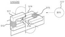
도 3은 도 1의 제1 임피던스 정합기에 구성된 가변 인덕터의 구조를 보여주는 사시도이다.3 is a perspective view illustrating a structure of a variable inductor configured in the first impedance matcher of FIG. 1.
도 4a 내지 도 4c는 도 3의 제1 및 제2 마그네틱 코어의 상대적 위치가 가변되는 다양한 경우를 예시하는 도면이다.4A to 4C are diagrams illustrating various cases in which the relative positions of the first and second magnetic cores of FIG. 3 vary.
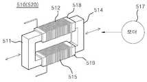
도 5는 도 1의 임피던스 정합기에 구성되는 가변 인덕터의 다른 예를 보여주는 사시도이다.5 is a perspective view illustrating another example of a variable inductor configured in the impedance matcher of FIG. 1.
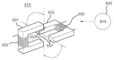
도 6은 도 1의 점화 전원 공급부에 구성된 가변 트랜스포머의 구조를 보여주는 사시도이다.FIG. 6 is a perspective view illustrating a structure of a variable transformer configured in the ignition power supply of FIG. 1.
도 7a 내지 도 7c는 도 6의 가변 트랜스포머의 가변 제어 방식을 설명하기 위한 도면이다.7A to 7C are diagrams for describing a variable control method of the variable transformer of FIG. 6.
도 8 및 도 9는 본 발명의 멀티 챔버 플라즈마 프로세스 시스템에 채용된 프로세스 챔버의 일 예를 보여주는 사시도 및 단면도이다.8 and 9 are a perspective view and a cross-sectional view showing an example of a process chamber employed in the multi-chamber plasma process system of the present invention.
도 10은 도 8에 도시된 프로세스 챔버의 변형예를 보여주는 사시도이다.FIG. 10 is a perspective view illustrating a modification of the process chamber illustrated in FIG. 8.
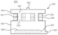
도 11 및 도 12는 본 발명의 멀티 챔버 플라즈마 프로세스 시스템에 채용된 프로세스 챔버의 다른 예를 보여주는 사시도 및 단면도이다.11 and 12 are a perspective view and a cross-sectional view showing another example of a process chamber employed in the multi-chamber plasma process system of the present invention.
도 13 및 도 14는 본 발명의 멀티 챔버 플라즈마 프로세스 시스템에 채용된 프로세스 챔버의 또 다른 예를 보여주는 사시도 및 단면도이다.13 and 14 are a perspective view and a cross-sectional view showing yet another example of a process chamber employed in the multi-chamber plasma process system of the present invention.
도 15는 플라즈마 밀도 조절 기능을 구비한 멀티 챔버 플라즈마 프로세스 시스템의 회로적 구성도이다.15 is a circuit diagram of a multi-chamber plasma process system having a plasma density control function.
도 16 내지 도 18은 본 발명의 멀티 챔버 플라즈마 프로세스 시스템에 채용된 프로세스 챔버들에 플라즈마 밀도 조절기가 구성된 예들을 보여주는 단면도이다.16 to 18 are cross-sectional views illustrating examples in which a plasma density regulator is configured in process chambers employed in the multi-chamber plasma process system of the present invention.
*도면의 주요 부분에 대한 부호의 설명** Description of the symbols for the main parts of the drawings *
100, 110, 120: 프로세스 챔버200, 210, 220: 제2 임피던스정합기100, 110, 120:
300, 310, 320: 바이어스 전원400: 주전원 공급원300, 310, 320: bias power 400: main power supply
500: 제1 임피던스 정합기600: 점화 전원 공급원500: first impedance matcher 600: ignition power source
700: 제어부700: control unit
본 발명은 멀티 챔버 시스템에 관한 것으로, 구체적으로는 유도 결함 플라즈마 방식의 프로세스 챔버를 다중으로 구성하여 반도체 기판이나 액정 유리 기판과 같은 피처리 기판을 병렬로 처리할 수 있는 멀티 챔버 플라즈마 프로세스 시스템에 관한 것이다.The present invention relates to a multi-chamber system, and more particularly, to a multi-chamber plasma process system capable of processing a substrate to be processed in parallel, such as a semiconductor substrate or a liquid crystal glass substrate, by constructing multiple process chambers of inductive defect plasma. will be.
잘 알려진 바와 같이, 반도체 집적회로장치나 액정표시장치를 제조하기 위한 반도체 제조 산업에서는 생산성을 높이기 위해 멀티 챔버 시스템이 실용화 되어 있다. 멀티 챔버 시스템은 다수개의 프로세스 챔버를 클러스터 타입으로 배치하거나, 컨베이어 또는 트랙으로 기판 흐름 경로를 갖게 하고 그 주변에 다수의 프로세스 챔버를 배치하는 구조를 갖는다. 멀티 챔버 시스템에서 프로세스 챔버는 수평 배열되거나 또는 두 개 이상 적층시켜 구성하기도 한다.As is well known, in the semiconductor manufacturing industry for manufacturing a semiconductor integrated circuit device or a liquid crystal display device, a multi-chamber system has been put to practical use to increase productivity. The multi-chamber system has a structure in which a plurality of process chambers are arranged in a cluster type or have a substrate flow path to a conveyor or a track, and a plurality of process chambers are arranged around them. In a multi-chamber system, the process chambers may be arranged horizontally or stacked in two or more.
최근의 반도체 제조 산업에서는 피처리 기판의 대구경화와 직접회로의 미세패턴화, 고정밀화, 복잡화 등에 따른 복합 프로세스의 증가와 일괄 처리에 의한 공정의 단축화가 요구되고 있다. 이러한 점에서 멀티 챔버 시스템은 복합 프로세스의 대응을 용이하게 하고, 일괄 처리에 의한 공정의 단축화로 생산성을 향상시킬 수 있다.In the recent semiconductor manufacturing industry, there is a demand for an increase in complex processes due to large diameters of substrates to be processed, fine patterning of integrated circuits, high precision, and complexity, and shortening of processes by batch processing. In this regard, the multi-chamber system facilitates the coping of complex processes and can improve productivity by shortening the process by batch processing.
단위 면적당 생산성을 높이기 위하여 멀티 챔버 시스템에서도 각 구성들을 보다 효과적으로 배치하고 통합화 될 수 있는 부분들은 통합될 필요가 있다. 대부분의 멀티 챔버 시스템에서 다수의 프로세스 챔버들은 각기 개별적인 전원 공급 구조를 갖고 있어서 비효율적인 면이 있다고 할 수 있다. 그럼으로 멀티 챔버 시스템은 전원 공급 구조에 있어서 효과적인 통합화에 의하여 설비의 면적과 비용을 감 소시킬 필요가 있다.In order to increase productivity per unit area, parts that can be more effectively placed and integrated in multi-chamber systems need to be integrated. In most multi-chamber systems, multiple process chambers each have their own power supply structure, which is inefficient. As a result, multichamber systems need to reduce the area and cost of equipment by effective integration in the power supply structure.
한편, 반도체 제조 공정에서 널리 사용되는 플라즈마 프로세스는 플라즈마를 발생시키는 것과 플라즈마 밀도를 공정 특성에 따라 적절히 유지하는 것이 매우 중요하다. 유도 결합 플라즈마 방식을 채용한 플라즈마 프로세스 챔버를 구비하는 멀티 챔버 시스템에서 전원 공급 구조를 효과적으로 통합화하기 위해서는 점화 전원의 공급, 고주파 전원의 공급, 그리고 임피던스 정합 등을 잘 고려하여 설계하여야 한다. 또한 공정 특성에 따라 각 프로세스 챔버의 플라즈마 밀도를 조절할 수 있어야 한다.On the other hand, in the plasma process widely used in the semiconductor manufacturing process, it is very important to generate plasma and maintain the plasma density appropriately according to the process characteristics. In order to effectively integrate a power supply structure in a multi-chamber system having a plasma process chamber employing an inductively coupled plasma method, the design of the ignition power supply, the high frequency power supply, and the impedance matching should be well considered. In addition, the plasma density of each process chamber should be adjusted according to the process characteristics.
이에 따라, 본 발명은 유도 결합 플라즈마 방식의 프로세스 챔버를 구비하는 멀티 챔버 시스템에 있어서 점화 전원, 고주파 전원, 임피던스 정합기 등을 포함하는 전원 공급 계통을 효과적으로 통합 구성하여 멀티 챔버 시스템의 설비 면적과 비용을 절감하고 각 프로세스 챔버의 플라즈마 밀도를 개별적으로 제어할 수 있도록 하여 공정 수율을 향상 시킬 수 있도록 함으로서 전체적으로 멀티 챔버 시스템의 생산성을 향상 시킬 수 있는 멀티 챔버 플라즈마 프로세스 시스템을 제공하는데 있다.Accordingly, the present invention effectively integrates and configures a power supply system including an ignition power source, a high frequency power source, an impedance matcher, and the like in a multi-chamber system having an inductively coupled plasma process chamber. It is to provide a multi-chamber plasma process system that can improve the overall productivity of the multi-chamber system by reducing the cost and to control the plasma density of each process chamber to improve the process yield.
상기한 기술적 과제를 달성하기 위한 본 발명의 일면은 멀티 챔버 플라즈마 프로세스 시스템에 관한 것이다. 본 발명의 멀티 챔버 플라즈마 프로세스 시스템은: 유도 결합 플라즈마 발생기를 각기 구비하는 복수개의 프로세스 챔버; 각각의 유도 결합 플라즈마 발생기로 플라즈마 발생을 위한 RF 전원을 공급하는 주전원 공급원; 주전원 공급원과 유도 결합 플라즈마 발생기 사이에 연결되는 제1 임피던스 정합기; 주전원 공급원으로부터 RF 전원을 공급 받아 유도 결합 플라즈마 발생기에 구비된 점화 전극으로 점화 전원을 공급하는 점화 전원 공급부; 복수개의 프로세서 챔버들에 구비되는 각각의 서셉터로 각기 바이어스 전원을 공급하기 위한 복수개의 바이어스 전원; 복수개의 프로세서 챔버들에 구비되는 각각의 서셉터와 그에 대응된 바이어스 전원 사이에 연결되는 복수개의 제2 임피던스 정합기 및; 제1 임피던스 정합기와 복수개의 제2 임피던스 정합기 및 점화 전원 공급원을 제어하는 제어부를 포함한다.One aspect of the present invention for achieving the above technical problem relates to a multi-chamber plasma process system. The multi-chamber plasma process system of the present invention comprises: a plurality of process chambers each having an inductively coupled plasma generator; A main power supply for supplying RF power for plasma generation to each inductively coupled plasma generator; A first impedance matcher coupled between the main power source and the inductively coupled plasma generator; An ignition power supply unit receiving RF power from a main power source and supplying ignition power to an ignition electrode provided in the inductively coupled plasma generator; A plurality of bias power supplies for supplying bias power to respective susceptors provided in the plurality of processor chambers; A plurality of second impedance matchers connected between each susceptor provided in the plurality of processor chambers and a bias power source corresponding thereto; And a control unit controlling a first impedance matcher, a plurality of second impedance matchers, and an ignition power supply.
본 발명의 바람직한 실시예에 있어서, 상기 복수개의 프로세스 챔버에 구비되는 유도 결합 플라즈마 발생기는 제1 임피던스 정합기를 통하여 주전원 공급원에 전기적으로 직렬로 연결되고, 유도 결합 플라즈마 발생기에 구비되는 점화 전극은 점화 전원 공급부에 병렬로 연결된다.In a preferred embodiment of the present invention, the inductively coupled plasma generator provided in the plurality of process chambers is electrically connected in series to a main power supply source through a first impedance matcher, and the ignition electrode provided in the inductively coupled plasma generator is an ignition power source. It is connected in parallel to the supply.
본 발명의 바람직한 실시예에 있어서, 상기 복수개의 프로세스 챔버는 적어도 두 개의 프로세스 챔버가 적층된 구조를 갖거나 또는 클러스터 구조를 갖는다.In a preferred embodiment of the present invention, the plurality of process chambers have a structure in which at least two process chambers are stacked or have a cluster structure.
본 발명의 바람직한 실시예에 있어서, 상기 제1 임피던스 정합기 및 복수개의 제2 임피던스 정합기는 각기 임피던스 정합을 위한 적어도 하나의 가변 인덕터를 포함하고, 상기 가변 인덕터는: 말굽 형상을 갖고 양단이 마주 대향하도록 배치된 제1 및 제2 마그네틱 코어; 제1 및 제2 마그네틱 코어에 각기 감겨진 연속된 제1 및 제2 권선 코일 및; 상기 제어부의 제어에 따라서 제1 및/또는 제2 마그네틱 코어를 이동시켜 제1 및 제2 마그네틱 코어의 상대적 위치를 가변시키는 구동 수단을 포함한다. 그리고 상기 가변 인덕터는 제1 및 제2 마그네틱 코어의 상대적 위치가 가변됨에 따라 제1 및 제2 권선 코일에 의해 유기되는 자속의 방향이 상호 일치하거나 엇갈리거나 또는 역방향을 갖게 됨으로서 제1 및 제2 권선 코일에 의한 인덕턴스가 가변되고, 또는 상기 가변 인덕터는 제1 및 제2 마그네틱 코어의 상대적 거리가 가변됨에 따라 제1 및 제2 권선 코일에 의해 유기되는 자속이 제1 및 제2 마그네틱 코어에 집속되는 자속수가 증가하거나 감소하여 제1 및 제2 권선 코일에 의한 인덕턴스가 가변된다.In a preferred embodiment of the present invention, the first impedance matcher and the plurality of second impedance matchers each include at least one variable inductor for impedance matching, the variable inductor having a horseshoe shape and opposing opposite ends. First and second magnetic cores disposed so as to; Continuous first and second winding coils respectively wound around the first and second magnetic cores; And driving means for varying the relative positions of the first and second magnetic cores by moving the first and / or second magnetic cores under the control of the controller. The first and second windings of the variable inductor have mutually coincidental, staggered, or reverse directions of magnetic flux induced by the first and second winding coils as the relative positions of the first and second magnetic cores are varied. The inductance caused by the coil is variable, or the magnetic flux induced by the first and second winding coils is focused on the first and second magnetic cores as the variable inductor varies with the relative distance of the first and second magnetic cores. The number of magnetic fluxes increases or decreases so that the inductance by the first and second winding coils is variable.
본 발명의 바람직한 실시예에 있어서, 상기 제1 임피던스 정합기 및 복수개의 제2 임피던스 정합기는 각기 임피던스 정합을 위한 적어도 하나의 가변 인덕터를 포함하고, 상기 가변 인덕터는: 양단이 개방되고 병렬로 배열된 제1 및 제2 중공형 튜브; 제1 및 제2 중공형 튜브에 각기 권선되는 연속된 제1 및 제2 권선 코일; 말굽 형상을 갖고 양단이 마주 대향하도록 제1 및 제2 중공형 튜브에 장착되는 제1 및 제2 마그네틱 코어 및; 상기 제어부의 제어에 따라서 제1 및/또는 제2 마그네틱 코어를 이동시켜 상대적 거리를 변화시키는 구동 수단을 포함한다. 그리고 상기 가변 인덕터는 제1 및 제2 마그네틱 코어의 상대적 거리가 가변됨에 따라 제1 및 제2 권선 코일에 의해 유기되는 자속이 제1 및 제2 마그네틱 코어에 집속되는 자속수가 증가하거나 감소하여 제1 및 제2 권선 코일에 의한 인덕턴스가 가변된다. 상기 제1 및 제2 중공형 튜브는 절연체로 구성되는 것이 바람직하다.In a preferred embodiment of the present invention, the first impedance matcher and the plurality of second impedance matchers each include at least one variable inductor for impedance matching, wherein the variable inductor is open at both ends and arranged in parallel. First and second hollow tubes; Continuous first and second winding coils respectively wound around the first and second hollow tubes; First and second magnetic cores having a horseshoe shape and mounted to the first and second hollow tubes so that opposite ends thereof face each other; And driving means for changing the relative distance by moving the first and / or second magnetic cores under the control of the controller. In the variable inductor, as the relative distance between the first and second magnetic cores varies, the magnetic flux induced by the first and second winding coils increases or decreases the number of magnetic fluxes focused on the first and second magnetic cores. And an inductance by the second winding coil is variable. Preferably, the first and second hollow tubes are composed of an insulator.
본 발명의 바람직한 실시예에 있어서, 상기 점화전원 공급부는 일차측이 전 원 공급원에 연결되고 이차측이 복수개의 유도 결합 플라즈마 발생기의 점화 전극에 병렬로 연결되는 가변 트랜스포머를 포함하며, 상기 가변 트랜스포머는: 말굽 형상을 갖고 양단이 마주 대향하도록 배치된 제1 및 제2 마그네틱 코어; 제1 마그네틱 코어에 감겨진 1차측 권선 코일; 제2 마그네틱 코어에 감겨진 2차측 권선 코일 및; 상기 제어부의 제어에 따라서 제1 및/또는 제2 마그네틱 코어를 이동시켜 제1 및 제2 마그네틱 코어의 상대적 위치를 가변시키는 구동 수단을 포함한다. 그리고 상기 가변 트랜스포머는 제1 및 제2 마그네틱 코어의 상대적 위치가 가변됨에 따라 제1 마그네틱 코어와 제2 마그네틱 코어에 공통으로 집속되는 자속수가 증가하거나 감소하여 1차측 권선 코일로부터 2차측 권선코일로 전달되는 유도 기전력이 가변된다.In a preferred embodiment of the present invention, the ignition power supply includes a variable transformer whose primary side is connected to a power source and the secondary side is connected in parallel to the ignition electrodes of the plurality of inductively coupled plasma generators. : First and second magnetic cores having a horseshoe shape and arranged opposite to each other; A primary winding coil wound around the first magnetic core; A secondary winding coil wound around a second magnetic core; And driving means for varying the relative positions of the first and second magnetic cores by moving the first and / or second magnetic cores under the control of the controller. In addition, as the variable transformer has a variable relative position of the first and second magnetic cores, the number of magnetic fluxes that are focused on the first magnetic core and the second magnetic core increases or decreases, and is then transferred from the primary winding coil to the secondary winding coil. The induced electromotive force is varied.
본 발명의 바람직한 실시예에 있어서, 상기 복수개의 프로세스 챔버는 피처리 기판이 놓이는 서셉터가 위치한 챔버 하우징의 천정에 적어도 두 개의 홀을 구비하고, 상기 유도 결합 플라즈마 발생기는: 적어도 두 개의 홀에 양단이 결합되는 적어도 하나의 중공형의 C 형상의 외부 방전 브리지; 외부 방전 브리지에 장착되는 적어도 하나의 도넛형상의 마그네틱 코어 및; 마그네틱 코어에 권선되며 제1 임피던스 정합기를 통하여 주전원 공급원에 연결되는 유도 코일을 포함하여, 유도 코일에 의해 유도되는 기전력에 의해 외부 방전 브리지의 내부와 챔버 하우징의 내부를 통해 플라즈마 방전 패스가 형성된다. 상기 외부 방전 브리지와 챔버 하우징의 내측면 전체적으로 절연체층이 구비되는 것이 바람직하다.In a preferred embodiment of the invention, the plurality of process chambers have at least two holes in the ceiling of the chamber housing in which the susceptor on which the substrate is to be placed is located, and the inductively coupled plasma generator comprises: At least one hollow C-shaped external discharge bridge coupled thereto; At least one donut-shaped magnetic core mounted to an external discharge bridge; A plasma discharge pass is formed through the interior of the external discharge bridge and the interior of the chamber housing by electromotive force induced by the induction coil, including an induction coil wound around the magnetic core and connected to the main power source through a first impedance matcher. It is preferable that an insulator layer is provided on the entire inner surface of the outer discharge bridge and the chamber housing.
본 발명의 바람직한 실시예에 있어서, 유도 결합 플라즈마 발생기는 플라즈 마 밀도 조절기를 포함하고, 플라즈마 밀도 조절기는: 외부 방전 브리지의 내측 상부 방전 공간을 가로질러서 전체적으로 설치되는 다공홀이 형성된 밀도 조절 평판 및; 밀도 조절 평판을 상하로 수직 이동시키기 위한 구동 수단을 포함하여, 밀도 조절 평판이 상측으로 이동됨에 따라 플라즈마 밀도가 증가하고 하측으로 이동됨에 따라 플라즈마 밀도가 감소한다.In a preferred embodiment of the present invention, the inductively coupled plasma generator comprises a plasma density regulator, the plasma density regulator comprising: a density regulating plate having a perforated hole formed entirely across the inner upper discharge space of the outer discharge bridge; Including a drive means for vertically moving the density control plate vertically, the plasma density increases as the density control plate is moved upwards and the plasma density decreases as it is moved downwards.
상기 복수개의 프로세스 챔버는 피처리 작업편이 놓이는 서셉터가 위치한 챔버 하우징의 천정에 복수개의 홀을 구비하고, 상기 유도 결합 플라즈마 발생기는: 챔버 하우징 천정의 복수개의 홀과 대응하는 개수의 홀이 하부면에 구비되며, 상부면에 가스 입구가 구비된 중공형 방전관 헤드; 챔버 하우징 천정의 복수개의 홀과 그에 대응된 방전관 헤드 하부면의 복수개의 홀 사이에 연결되는 복수개의 중공형 방전관 브리지; 중공형 방전관 브리지에 장착되는 도넛 형상의 마그네틱 코어 및; 마그네틱 코어에 권선되며 제1 임피던스 정합기를 통하여 주전원 공급원에 연결되는 유도 코일을 포함하여, 유도 코일에 의해 유도되는 기전력에 의해 중공형 방전관 헤드와 복수개의 중공형 방전관 브리지 그리고 챔버 하우징의 내부를 연결하는 플라즈마 방전 패스가 형성된다. 상기 복수개의 중공형 방전관 브리지중 적어도 하나의 중공형 방전관 브리지에는 마그네틱 코어가 장착되지 않을 수 있다. 그리고 상기 중공형 방전관 헤드와 복수개의 중공형 방전 브리지 및 챔버 하우징의 내측면은 전체적으로 절연체층이 구비되는 것이 바람직하다.The plurality of process chambers have a plurality of holes in the ceiling of the chamber housing in which the susceptor on which the workpiece is to be placed is located, wherein the inductively coupled plasma generator comprises: a plurality of holes in the chamber housing ceiling and a corresponding number of holes on the bottom surface of the chamber; A hollow discharge tube head provided in the upper surface and having a gas inlet; A plurality of hollow discharge tube bridges connected between the plurality of holes of the chamber housing ceiling and the plurality of holes of the lower surface of the discharge tube head corresponding thereto; A donut-shaped magnetic core mounted to the hollow discharge tube bridge; A hollow discharge tube head, a plurality of hollow discharge tube bridges and an interior of the chamber housing by electromotive force induced by the induction coil, including an induction coil wound around the magnetic core and connected to a main power source through a first impedance matcher. A plasma discharge pass is formed. At least one hollow discharge tube bridge of the plurality of hollow discharge tube bridges may not be equipped with a magnetic core. The inner surface of the hollow discharge tube head, the plurality of hollow discharge bridges, and the chamber housing is preferably provided with an insulator layer as a whole.
본 발명의 바람직한 실시예에 있어서, 유도 결합 플라즈마 발생기는 플라즈마 밀도 조절기를 포함하고, 플라즈마 밀도 조절기는: 중공형 방전관 헤드의 내측 방전 공간을 가로질러서 전체적으로 설치되는 다공홀이 형성된 밀도 조절 평판 및; 밀도 조절 평판을 상하로 수직 이동시키기 위한 구동 수단을 포함하고, 밀도 조절 평판이 상측으로 이동됨에 따라 플라즈마 밀도가 증가하고 하측으로 이동됨에 따라 플라즈마 밀도가 감소한다.In a preferred embodiment of the present invention, the inductively coupled plasma generator comprises a plasma density regulator, the plasma density regulator comprising: a density regulating plate having a hole formed entirely across the inner discharge space of the hollow discharge tube head; And driving means for vertically moving the density regulating plate vertically, wherein the plasma density increases as the density regulating plate is moved upwards, and the plasma density decreases as it moves downward.
본 발명의 바람직한 실시예, 상기 복수개의 프로세스 챔버는 서셉터가 놓이는 챔버 하우징의 내측 상부 공간에 유도 결합 플라즈마 발생기가 배치되며, 상기 유도 결합 플라즈마 발생기는: 챔버 하우징의 상부 공간에 위치하는 링형의 중공형 코어 재킷; 중공형 코어 재킷을 챔버 하우징의 상부 공간에 고정하도록 챔버 하우징의 상부 측벽으로부터 중공형 코어 재킷에 연장되어 설치되는 적어도 하나의 고정 브리지; 코어 재킷의 내부에 탑재되는 링형의 마그네틱 코어 및; 마그네틱 코어에 권선되며 제1 임피던스 정합기를 통하여 주전원 공급원에 연결되는 유도 코일을 포함하며, 유도 코일에 의해 유도되는 기전력에 의해 중공형 코어 재킷의 외부를 전체적으로 감싸는 플라즈마 방전 패스가 형성된다. 상기 중공형 코어 재킷과 고정 브리지는 절연체로 구성되며, 챔버 하우징의 내측면은 전체적으로 절연체층이 구비되는 것이 바람직하다.In a preferred embodiment of the present invention, the plurality of process chambers are arranged with an inductively coupled plasma generator in an upper space inside the chamber housing in which the susceptor is placed, the inductively coupled plasma generator comprising: a ring-shaped hollow located in the upper space of the chamber housing; Type core jacket; At least one fixed bridge extending from the upper sidewall of the chamber housing to the hollow core jacket to secure the hollow core jacket to the upper space of the chamber housing; A ring-shaped magnetic core mounted inside the core jacket; And an induction coil wound around the magnetic core and connected to the main power source through the first impedance matcher, and an electromotive force induced by the induction coil forms a plasma discharge path that entirely surrounds the outside of the hollow core jacket. The hollow core jacket and the fixed bridge is composed of an insulator, and the inner surface of the chamber housing is preferably provided with an insulator layer as a whole.
본 발명의 바람직한 실시예에 있어서, 유도 결합 플라즈마 발생기는 플라즈마 밀도 조절기를 포함하고, 플라즈마 밀도 조절기는: 중공형 코어 재킷의 상부 영역으로 챔버 하우징의 내측 상부를 가로질러서 전체적으로 설치되며 다공홀이 형성된 밀도 조절 평판; 밀도 조절 평판을 상하로 수직 이동시키기 위한 구동 수단을 포함하고, 밀도 조절 평판이 상측으로 이동됨에 따라 플라즈마 밀도가 증가하고 하 측으로 이동됨에 따라 플라즈마 밀도가 감소한다.In a preferred embodiment of the present invention, the inductively coupled plasma generator comprises a plasma density regulator, the plasma density regulator comprising: a density which is installed entirely across the inner upper portion of the chamber housing to the upper region of the hollow core jacket and has pores formed therein. Adjustable reputation; And driving means for vertically moving the density regulating plate vertically, wherein the plasma density increases as the density regulating plate is moved upwards, and the plasma density decreases as it moves downward.
본 발명과 본 발명의 동작상의 이점 및 본 발명의 실시예에 의하여 달성되는 목적을 충분히 이해하기 위해서는 본 발명의 바람직한 실시예를 예시하는 첨부 도면 및 첨부 도면에 기재된 내용을 참조하여야 한다. 각 도면을 이해함에 있어서, 동일한 부재는 가능한 한 동일한 참조부호로 도시하고자 함에 유의하여야 한다. 그리고 본 발명의 요지를 불필요하게 흐릴 수 있다고 판단되는 공지 기능 및 구성에 대한 상세한 기술은 생략된다.DETAILED DESCRIPTION In order to fully understand the present invention, the operational advantages of the present invention, and the objects achieved by the embodiments of the present invention, reference should be made to the accompanying drawings which illustrate preferred embodiments of the present invention and the contents described in the accompanying drawings. In understanding the drawings, it should be noted that like parts are intended to be represented by the same reference numerals as much as possible. And detailed description of known functions and configurations that are determined to unnecessarily obscure the subject matter of the present invention is omitted.
(실시예)(Example)
이하, 첨부된 도면을 참조하여 본 발명의 바람직한 실시예를 설명함으로써, 본 발명의 멀티 챔버 플라즈마 프로세스 시스템을 상세히 설명한다.Hereinafter, the multi-chamber plasma process system of the present invention will be described in detail with reference to the accompanying drawings.
도 1은 본 발명의 멀티 챔버 플라즈마 프로세스 시스템의 전체 구성을 보여주는 회로적 구성도이다.1 is a circuit diagram showing the overall configuration of a multi-chamber plasma process system of the present invention.
본 발명의 멀티 챔버 플라즈마 프로세스 시스템은 복수개의 프로세스 챔버(100, 110, 120)를 구비한다. 복수개의 프로세스 챔버(100, 110, 120)는 각기 유도 결합 플라즈마 발생기(101, 111, 121)를 구비한다. 복수개의 유도 결합 플라즈마 발생기(101, 111, 121)는 각기 마그네틱 코어(101a, 111a, 121a)와 이에 권선되는 권선 코일(101b, 111b, 121b)을 구비한다. 복수개의 유도 결합 플라즈마 발생기(101, 111, 121)는 전기적으로 직렬로 연결되며, 제1 임피던스 정합기(500)를 통하여 주전원 공급원(400)에 연결된다.The multi-chamber plasma process system of the present invention includes a plurality of
주전원 공급원(400)은 RF 전원을 제1 임피던스 정합기(500)를 통하여 복수개 의 유도 결합 플라즈마 발생기(101, 111, 121)로 공급한다. 주전원 공급원(400)은 점화 전원 공급부(600)로 RF 전원을 공급한다. 점화 전원 공급부(600)는 주전원 공급원(400)으로부터 RF 전원을 공급 받아 복수개의 유도 결합 플라즈마 발생기(101, 111, 121)에 구비된 점화 전극(104, 114, 124)으로 점화 전원을 공급한다.The
복수개의 프로세서 챔버(100, 110, 120)들에 구비되는 각각의 서셉터(103, 113, 123)는 각기 제2 임피던스 정합기(200, 210, 220)를 통하여 해당 바이어스 전원(300, 310, 320)에 연결된다.Each of the
제1 임피던스 정합기(500)와 복수개의 제2 임피던스 정합기(200, 210, 220) 그리고 점화 전원 공급원(600)은 제어부(700)에 의해서 제어된다. 제어부(700)는 임피던스 정합을 위하여 제1 임피던스 정합기(500)를 제어하기 위한 제1 제어신호(701)와 점화 전원 공급원(600)을 제어하기 위한 제2 제어신호(702) 그리고 복수개의 제2 임피던스 정합기(200, 210, 220)를 제어하기 위한 제3 제어신호(703)를 각각 출력한다.The
제1 임피던스 정합기(500)는 입출력단 사이에 직렬로 연결되는 제1 및 제2 가변 인덕터(510, 520)와 제1 및 제2 가변 인덕터(510, 520)의 접속 노드와 접지 사이에 연결되는 커패시터(530)를 구비한다. 제1 및 제2 가변 인덕터(510, 520)는 제어부(700)의 제1 제어 신호(701)에 따라서 인덕턴스 값이 가변된다. 제1 및 제2 가변 인덕터(510, 520)의 구체적인 설명은 후술한다.The
점화 전원 공급원(600)은 가변 트랜스포머(610)로 구성되며, 가변 트랜스포머(610)의 1차측은 주전원 공급원(400)에 연결되고, 2차측은 복수개의 유도 결합 플라즈마 발생기(101, 111, 121)의 점화 전극(104, 114, 124)에 병렬로 연결된다. 가변 트랜스포머(610)는 제어부(700)의 제2 제어신호(702)에 따라서 2차측 유도 전압이 가변된다. 구체적인 설명은 후술되겠지만, 제어부(700)는 복수개의 유도 결합 플라즈마 발생기(101, 111, 121)의 플라즈마 점화 단계에서 점화 전원 공급부(600)가 점화 전원을 공급하도록 하며, 플라즈마 방전이 발생된 후에는 점화 전원 공급부(600)로부터 점화 전원이 공급되는 것이 차단되도록 가변 트랜스포머(610)를 동작 시키는 단속 기능을 수행한다.The
복수개의 제2 임피던스 정합기(200, 210, 220)는 상술한 제1 임피던스 정합기(500)의 구성과 동일하게 구성될 수 있으며, 제2 임피던스 정합기(200, 210, 220)는 제어부(700)의 제3 제어 신호(703)에 따라서 임피던스 정합을 위한 동작을 수행한다.The plurality of
도 2는 본 발명의 멀티 챔버 플라즈마 프로세스 시스템에 있어서 프로세스 챔버를 적층 구조로 구성한 예를 보여주는 도면이다.2 is a view showing an example in which the process chamber is configured in a stacked structure in the multi-chamber plasma process system of the present invention.
도 2에 도시된 바와 같이, 본 발명의 멀티 챔버 플라즈마 프로세스 시스템(800)은 이송챔버(850)에 적어도 두 개의 프로세스 챔버(810)가 수직으로 적층된 구조를 갖도록 구성될 수 있다. 적층된 프로세스 챔버(810)는 앞단에는 수직으로 승하강 가능한 이송 로봇(840)이 구비되며, 일 측으로는 하나 이상의 냉각 또는 가열 스테이지(820)가 적층 구성된다.As shown in FIG. 2, the multi-chamber
이와 같이, 본 발명의 멀티 챔버 플라즈마 처리 시스템은 적어도 두 개의 프로세스 챔버를 적층하여 구성할 수 있으며, 복수개의 프로세스 챔버들을 클러스터 구조를 배치하여 구성할 수 도 있다. 그리고 구체적으로 설명되지는 않았으나 트랙 시스템이나 컨베이어 시스템과 같은 이송 시스템을 사용하여 복수개의 프로세스 챔버를 다양한 구조로 배치 가능할 것이다.As described above, the multi-chamber plasma processing system of the present invention may be configured by stacking at least two process chambers, and may configure a plurality of process chambers by arranging a cluster structure. Although not specifically described, a plurality of process chambers may be arranged in various structures using a transport system such as a track system or a conveyor system.
본 발명의 멀티 챔버 플라즈마 프로세스 시스템은 적층된 구조나 클러스터 구조 형태로 집약된 배치 구조를 갖도록 함과 아울러 점화 전원, 고주파 전원, 임피던스 정합기 등을 포함하는 전원 공급 계통을 효과적으로 통합 구성하여 생산성을 향상시킬 수 있음은 물론 설비 면적과 비용을 효과적으로 절감할 수 있다.The multi-chamber plasma process system of the present invention improves productivity by effectively integrating a power supply system including an ignition power source, a high frequency power source, an impedance matcher, and the like in a stacked structure or a cluster structure. In addition, the size and cost of the plant can be effectively reduced.
도 3은 도 1의 제1 임피던스 정합기에 구성된 가변 인덕터의 구조를 보여주는 사시도이다.3 is a perspective view illustrating a structure of a variable inductor configured in the first impedance matcher of FIG. 1.
도 3을 참조하여, 제1 임피던스 정합기(500)에 구성된 가변 인덕터(510, 520)는 고주파 고전력에 적합한 구조를 제공한다. 가변 인덕터(510, 520)는 말굽 형상을 갖고 양단이 마주 대향하도록 배치된 제1 및 제2 마그네틱 코어(511, 514)를 구비한다. 제1 및 제2 마그네틱 코어(511, 514)에는 각기 제1 및 제2 권선 코일(512, 515)이 감겨진다. 제1 및 제2 권선 코일(512, 515)은 연속된 권선으로 구성된다.Referring to FIG. 3, the
가변 인덕터(510, 520)는 제1 및 제2 마그네틱 코어(511, 514)의 상대적 위치를 가변 시켜 제1 및 제2 권선 코일(512, 515)에 의한 인덕턴스를 가변 시키기 위한 구동 수단(517)을 구비한다. 구동 수단(517)은 예를 들어, 전기 모터로 구성될 수 있다. 구동 수단(517)은 제어부(700)의 제1 제어 신호(701)에 의해서 제어된다.
구동 수단(517)에 의해 제1 및 제2 마그네틱 코어(511, 514)의 상대적 위치가 가변됨으로서 가변 인덕터(510, 520)의 인덕턴스를 가변시키기는 다양한 경우가 첨부 도면 도 4a 내지 도 4c에 도시되어 있다.Various cases of varying inductances of the
도 4a에 도시된 바와 같이, 제1 및 제2 마그네틱 코어(511, 514)는 구동 수단(517)에 의해서 자속 입출력 부분(513, 516)이 일치되거나 엇갈리도록 수직(또는 수평) 방향으로 이동된다. 이 경우 엇갈리는 정도에 따라 가변 인덕터(510, 520)의 인던턴스가 가변된다.As shown in FIG. 4A, the first and second
다른 예로, 도 4b에 도시된 바와 같이, 제1 및 제2 마그네틱 코어(511, 514)는 구동 수단(517)에 의해서 자속 입출력 부분(513, 516)이 상호 일치하거나 엇갈리거나 역방향을 갖도록 회전된다. 이 경우, 회전하는 각도에 따라 가변 인덕터(510, 520)의 인덕턴스가 가변된다.As another example, as shown in FIG. 4B, the first and second
이상과 같이, 가변 인덕터(510, 520)는 제1 및 제2 마그네틱 코어(511, 514)의 상대적 위치(수직 또는 수평 방향으로 엇갈리는 정도, 엇갈리는 회전 각도)가 가변됨에 따라 제1 및 제2 권선 코일(512, 515)에 의해 유기되는 자속의 방향이 상호 일치하거나 엇갈리거나 또는 역방향을 갖게 됨으로서 제1 및 제2 권선 코일에 의한 인덕턴스가 가변된다.As described above, the
또 다른 예로, 도 4c에 도시된 바와 같이, 제1 및 제2 마그네틱 코어(511, 514)는 구동 수단(517)에 의해서 자속 입출력 부분(513, 516)의 상대적 거리가 가깝거나 멀게 이동된다. 이 경우 상대적 거리에 따라 가변 인덕터(510, 520)의 인던턴스가 가변된다. 즉, 가변 인덕터(510 520)는 제1 및 제2 마그네틱 코어(511, 514)의 상대적 거리가 가변됨에 따라 제1 및 제2 권선 코일(512, 515)에 의해 유기되는 자속이 제1 및 제2 마그네틱 코어(511, 514)에 집속되는 자속수가 증가하거나 감소하여 제1 및 제2 권선 코일(512, 515)에 의한 인덕턴스가 가변된다.As another example, as shown in FIG. 4C, the first and second
도 5는 도 1의 임피던스 정합기에 구성되는 가변 인덕터의 다른 예를 보여주는 사시도이다.5 is a perspective view illustrating another example of a variable inductor configured in the impedance matcher of FIG. 1.
도 5를 참조하여, 가변 인덕터(510, 520)는 양단이 개방되고 병렬로 배열된 제1 및 제2 중공형 튜브(518, 519)를 구비한다. 제1 및 제2 중공형 튜브(518, 519)는 절연체로 구성되는 것이 바람직하다. 제1 및 제2 중공형 튜브(518, 519)의 외측으로는 제1 및 제2 권선 코일(512, 515)이 감겨진다. 제1 및 제2 권선 코일(512, 515)은 연속된 권선으로 구성된다. 제1 및 제2 중공형 튜브(518, 519)에는 양측으로 말굽 형상의 제1 및 제2 마그네틱 코어(511, 514)가 마주 대향하도록 장착된다. 그리고 가변 인덕터(510, 520)는 제어부(700)의 제어에 따라서 제1 및/또는 제2 마그네틱 코어(511 and/or 514)를 이동시켜 상대적 거리를 변화시키기 위한 예컨대, 전기 모터와 같은 구동 수단(517)을 구비한다.Referring to FIG. 5, the
가변 인덕터(510, 520)는 제1 및 제2 마그네틱 코어(511, 514)의 상대적 거리가 가변됨에 따라 제1 및 제2 권선 코일(512, 515)에 의해 유기되는 자속이 제1 및 제2 마그네틱 코어(511, 514)에 집속되는 자속수가 증가하거나 감소하여 제1 및 제2 권선 코일(512, 515)에 의한 인덕턴스가 가변된다.The
이상과 같은 가변 인덕터(510, 520)는 복수개의 제2 임피던스 정합기(200, 210, 220)에도 동일하게 구성될 수 있으며, 복수개의 제2 임피던스 정합기(200, 210, 220)에 구비되는 가변 인덕터는 제어부(700)의 제3 제어 신호(703)에 따라서 임피던스 정합을 위한 제어 동작이 수행된다.The
도 6은 도 1의 점화 전원 공급부에 구성된 가변 트랜스포머의 구조를 보여주는 사시도이고, 도 7a 내지 도 7c는 도 6의 가변 트랜스포머의 가변 제어 방식을 설명하기 위한 도면이다.6 is a perspective view illustrating a structure of a variable transformer configured in the ignition power supply of FIG. 1, and FIGS. 7A to 7C are diagrams for describing a variable control method of the variable transformer of FIG. 6.
도 6을 참조하여, 점화 전원 공급부(600)에 구성되는 가변 트랜스포머(610)는 일차측이 주전원 공급원(400)에 연결되고 이차측이 복수개의 유도 결합 플라즈마 발생기(101, 111, 121)의 점화 전극(104, 114, 124)에 병렬로 연결된다.Referring to FIG. 6, the
가변 트랜스포머(610)는 말굽 형상을 갖고 양단이 마주 대향하도록 배치된 제1 및 제2 마그네틱 코어(601, 605)를 구비한다. 제1 마그네틱 코어(601)에는 1차측 권선 코일(602)이 권선되고, 제2 마그네틱 코어(605)에는 2차측 권선 코일(606)이 감겨진다. 여기서 제2 마그네틱 코어(601, 605)에 감겨진 1차측 및 2차측 권선코일(602, 606)은 연속된 권선이 아니다.The
가변 트랜스포머(610)는 예컨대, 전기 모터와 같은 구동 수단(609)을 구비한다. 구동 수단(609)은 제어부(700)의 제2 제어신호(702)에 따라 제1 및/또는 제2 마그네틱 코어(601 and/or 605)를 이동시켜서 상대적 위치를 가변 시킨다. 예를 들어, 수직 또는 수평 방향으로 엇갈리는 정도(도 7a 참조), 엇갈리는 회전 각도(도 7b 참조), 또는 상대적 거리(도 7c 참조)가 가변된다. 그럼으로 제1 마그네틱 코어(601)와 제2 마그네틱 코어(605)에 공통으로 집속되는 자속수가 증가하거나 감소하여 1차측 권선 코일(602)로부터 2차측 권선 코일(606)로 전달되는 유도 기전력 이 가변된다.The
가변 트랜스포머(610)를 구비하는 점화 전원 공급부(600)는 제어부(700)의 제어를 받아 복수개의 유도 결합 플라즈마 발생기(101, 111, 121)의 점화 전극들(104, 114, 124)로 플라즈마 점화를 위한 고주파 고전력의 전원을 공급한다. 그리고 플라즈마 방전이 발생된 후에는 제어부(700)의 제어에 따라 가변 트랜스포머(610)가 동작하여 점화 전원의 공급이 차단된다.The ignition
한편, 본 발명의 멀티 챔버 플라즈마 프로세스 시스템에 구비되는 복수개의 프로세스 챔버들(100, 110, 120)은 유도 결합 플라즈마 발생기(101, 111, 121)를 구비한다. 이들의 구조는 후술하는 바와 같이 다양하게 구현될 수 있다.Meanwhile, the plurality of
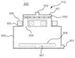
도 8 및 도 9는 본 발명의 멀티 챔버 플라즈마 프로세스 시스템에 채용된 프로세스 챔버의 일 예를 보여주는 사시도 및 단면도이다.8 and 9 are a perspective view and a cross-sectional view showing an example of a process chamber employed in the multi-chamber plasma process system of the present invention.
도 8 및 도 9를 참조하여, 본 발명의 멀티 챔버 플라즈마 프로세스 시스템에 채용된 일예의 프로세스 챔버(900)는 피처리기판(908)이 놓이는 서셉터(907)가 위치한 챔버 하우징(904)의 천정에 적어도 두 개의 홀(909a, 909b)을 구비한다. 두 개의 홀(909a, 909b)에는 유도 결합 플라즈마 발생기(910)가 결합된다.8 and 9, an
유도 결합 플라즈마 발생기(910)는 적어도 두 개의 홀(909a, 909b)에 양단이 결합되는 적어도 하나의 중공형의 C 형상의 외부 방전 브리지(901)를 구비한다. 외부 방전 브리지(901)에는 적어도 하나의 도넛형상의 마그네틱 코어(905)가 장착되며, 이 마그네틱 코어(905)에는 제1 임피던스 정합기(500)(도 1 참조)를 통하여 주전원 공급원(400)에 연결되는 유도 코일(906)이 감겨 있다. 그리고 외부 방전 브리지(901)의 상단 중심부에는 가스 유입구(902)가 구비되며, 챔버 하우징(904)의 하단에는 가스 배출구(903)가 구성된다.The inductively coupled
이와 같은 구조를 갖는 프로세스 챔버(900)는 유도 코일(906)에 의해 유도되는 기전력에 의해 외부 방전 브리지(901)의 내부와 챔버 하우징(904)의 내부를 통해 플라즈마 방전 패스가 형성된다. 프로세스 챔버(900)는 외부 방전 브리지(901)와 챔버 하우징(904)의 내측면 전체적으로 폴리머 방지를 위해 석영과 같은 절연체층(미도시)이 설치될 수 있다.In the
대면적의 피처리 기판의 처리를 위해서 프로세스 챔버(900)는, 도 10에 도시된 바와 같이, 챔버 하우징(904)의 천정에 두 개 이상의 유도 결합 플라즈마 반응기(910a, 910b)를 설치할 수 있다. 두 개 이상의 유도 결합 플라즈마 반응기(910a, 910b)를 설치하여 보다 넓은 볼륨과 향상된 균일도를 갖는 플라즈마를 발생할 수 있다.The
도 11 및 도 12는 본 발명의 멀티 챔버 플라즈마 프로세스 시스템에 채용된 프로세스 챔버의 다른 예를 보여주는 사시도 및 단면도이다.11 and 12 are a perspective view and a cross-sectional view showing another example of a process chamber employed in the multi-chamber plasma process system of the present invention.
도 11 및 도 12를 참조하여, 본 발명의 멀티 챔버 플라즈마 프로세스 시스템에 채용된 다른 예의 프로세스 챔버(920)는 피처리 작업편(928)이 놓이는 서셉터(927)가 놓이는 챔버 하우징(924)의 천정에 복수개의 홀(929)을 구비한다. 복수개의 홀(929)에는 유도 결합 플라즈마 발생기(930)가 결합된다.11 and 12, another
유도 결합 플라즈마 발생기(930)는 중공형 방전관 헤드(921)와 복수개의 중공형 방전관 브리지(931)를 구비한다. 중공형 방전관 헤드(921)는 상기 챔버 하우 징(924)의 천정에 형성된 복수개의 홀(929)과 대응하는 개수의 홀(932)이 하부면에 구비되며, 상부면에 가스 입구(922)가 구비된다. 복수개의 중공형 방전관 브리지(932)는 챔버 하우징(924) 천정의 복수개의 홀(929)과 그에 대응된 방전관 헤드(921) 하부면의 복수개의 홀(932) 사이에 각각 연결된다. 이 실시예에서 중공형 방전관 브리지(932)는 네 개가 사각형으로 배치되며, 이에 적합하게 챔버 하우징(924)의 천정에 네 개의 홀(929)이 그리고 중공형 방전관 헤드(921)의 저면에도 이에 적합하게 네 개의 홀(932)이 각각 형성된다.The inductively coupled
그리고 복수개의 중공형 방전관 브리지(931)에는 각기 도넛 형상의 마그네틱 코어(925)가 장착되며, 마그네틱 코어(925)에는 제1 임피던스 정합기(500)(도 1 참조)를 통하여 주전원 공급원(400)에 연결되는 유도 코일(926)이 감겨 있다.The plurality of hollow
이와 같은 프로세스 챔버(920)는 유도 코일(926)에 의해 유도되는 기전력에 의해 중공형 방전관 헤드(921)와 복수개의 중공형 방전관 브리지(931) 그리고 챔버 하우징(924)의 내부를 연결하는 플라즈마 방전 패스가 형성된다. 여기서, 복수개의 중공형 방전관 브리지(929)는 모두 유도 코일(926)이 감긴 마그네틱 코어(925)가 장착될 수 있다.The
또는 복수개의 중공형 방전관 브리지(923) 중 적어도 하나에는 마그네틱 코어가 장착되지 않을 수도 있다. 마그네틱 코어와 유도 코일이 장착되지 않은 중공형 방전관 브리지도 여전히 플라즈마 방전 패스가 형성된다. 그리고 대면적의 피처리 기판을 처리하기 위해 중공형 방전관 브리지(923)의 수를 증설할 수 있을 것이다.Alternatively, at least one of the plurality of hollow discharge tube bridges 923 may not be equipped with a magnetic core. Hollow discharge tube bridges without magnetic cores and induction coils still form plasma discharge paths. In addition, the number of hollow discharge tube bridges 923 may be increased to process a large-area target substrate.
상술한 예와 같이, 이 프로세스 챔버(920)에서도 중공형 방전관 헤드(921)와 복수개의 중공형 방전관 브리지(931) 그리고 챔버 하우징(924)의 내측면 전체적으로 폴리머 방지를 위해 석영과 같은 절연체층(미도시)이 설치될 수 있다.As in the above-described example, the
도 13 및 도 14는 본 발명의 멀티 챔버 플라즈마 프로세스 시스템에 채용된 프로세스 챔버의 또 다른 예를 보여주는 사시도 및 단면도이다.13 and 14 are a perspective view and a cross-sectional view showing yet another example of a process chamber employed in the multi-chamber plasma process system of the present invention.
도 13 및 도 14를 참조하여, 본 발명의 멀티 챔버 플라즈마 프로세스 시스템에 채용된 또 다른 예의 프로세스 챔버(940)는 피처리 작업편(948)이 놓이는 서셉터(947)가 놓이는 챔버 하우징(944)의 내측 상부 공간에 유도 결합 플라즈마 발생기(950)가 배치된다.With reference to FIGS. 13 and 14, another
유도 결합 플라즈마 발생기(950)는 챔버 하우징(924)의 상부 공간에 위치하는 링형의 중공형 코어 재킷(951)을 구비한다. 중공형 코어 재킷(951)은 챔버 하우징(944)의 상부 공간에 고정하도록 챔버 하우징(944)의 상부 측벽(941)으로부터 중공형 코어 재킷(951)에 연장되어 설치되는 적어도 하나의 고정 브리지(952)를 갖는다. 코어 재킷(951)의 내부에는 링형의 마그네틱 코어(945)와 마그네틱 코어(945)에 감겨진 유도 코일(946)을 탑재된다.Inductively coupled
유도 코일(946)은 제1 임피던스 정합기(500)(도 1 참조)를 통하여 주전원 공급원(400)에 연결된다. 챔버 하우징(944)의 상부 측벽(941)은 고정 브리지(952)가 연결되는 위치에 홀(943) 형성되며, 이를 통하여 유도 코일(946)이 외부로 연장되어 배출된다. 도면에는 구체적으로 도시하지 않았으나 홀(943)을 통해서 냉각수 공급이 이루어 질 수 있다.
이와 같은 프로세스 챔버(940)는 유도 코일(946)에 의해 유도되는 기전력에 의해 중공형 코어 재킷(951)의 외부를 전체적으로 감싸는 플라즈마 방전 패스가 형성된다. 그리고 대면적의 피처리 기판을 처리하기 위해 중공형 코어 재킷(951)의 사이즈를 크게 하고 또한 이에 적합하도록 마그네틱 코어(945)의 사이즈를 크게 할 수 있을 것이다. 또는 중공형 코어 재킷(951)과 마그네틱 코어(945)를 복수개 구비할 수도 있을 것이다.In the
상술한 예와 같이, 이 프로세스 챔버(940)에서도 중공형 코어 재킷(950)과 고정 브리지(952)를 폴리머 방지를 위해 석영과 같은 절연체로 구성하고, 챔버 하우징(924)의 내측면 또한 절연체층(미도시)이 설치될 수 있다.As in the above-described example, in the
이상에서 설명한 바와 같이, 본 발명의 멀티 챔버 플라즈마 프로세스 시스템은 구비되는 복수개의 프로세스 챔버 상술한 예에서와 같은 다양한 형태의 유도 결합 플라즈마 발생기를 구비할 수 있다. 그리고 후술하는 바와 같이, 복수개의 프로세스 챔버들은 각기 플라즈마 밀도 조절을 위한 조절기를 구비할 수 있다.As described above, the multi-chamber plasma process system of the present invention may be provided with a plurality of inductively coupled plasma generators as in the above-described examples of a plurality of process chambers. And as will be described later, the plurality of process chambers may each have a regulator for plasma density control.
도 15는 플라즈마 밀도 조절 기능을 구비한 멀티 챔버 플라즈마 프로세스 시스템의 회로적 구성도이다.15 is a circuit diagram of a multi-chamber plasma process system having a plasma density control function.
도 15를 참조하여, 플라즈마 밀도 조절 기능을 구비하는 멀티 챔버 플라즈마 프로세스 시스템의 전제적인 구성은 도 1에 도시된 바와 기본적으로 동일하게 구성된다. 다만, 복수개의 프로세스 챔버들(100, 110, 120)은 유도 결합 플라즈마 발생기(101, 111, 121)에 의해 발생되는 플라즈마의 밀도를 조절하기 위한 플라즈마 밀도 조절기(102, 112, 122)가 구비된다. 그리고 플라즈마 밀도 조절기(102, 112, 122)는 제어부(700)에서 제공되는 제3 제어 신호(704)에 의해서 제어된다.Referring to FIG. 15, the overall configuration of a multi-chamber plasma process system having a plasma density adjustment function is basically the same as that shown in FIG. 1. However, the plurality of
플라즈마 밀도 조절기는 후술되는 바와 같이, 밀도 조절 평판과 밀도 조절 평판을 구동시키기 위한 구동 수단으로 구성된다. 구동 수단은 제어부(700)의 제3 제어 신호(704)에 따라서 밀도 조절 평판을 구동 시킨다.The plasma density regulator is constituted by a driving means for driving the density adjusting plate and the density adjusting plate, as will be described later. The driving means drives the density adjusting plate according to the
도 16 내지 도 18은 본 발명의 멀티 챔버 플라즈마 프로세스 시스템에 채용된 프로세스 챔버들에 플라즈마 밀도 조절기가 구성된 예들을 보여주는 단면도이다.16 to 18 are cross-sectional views illustrating examples in which a plasma density regulator is configured in process chambers employed in the multi-chamber plasma process system of the present invention.
도 16에 도시된 바와 같이, 일 실시예의 프로세스 챔버(900)는 외부 방전 브리지(901)의 내측 상부 방전 공간을 가로질러서 전체적으로 설치되는 다공홀이 형성된 밀도 조절 평판(1000)이 장착된다. 그리고 밀도 조절 평판(1000)은 구동 수단(미도시)에 의해 상하로 수직 이동된다. 구동 수단은 예컨대, 유압이나 공압 밸브 또는 전기적이 모터와 기어 어셈블리 등 다양한 방식으로 구성될 수 있다.As shown in FIG. 16, the
도 17에 도시된 바와 같이, 다른 실시예의 프로세스 챔버(920)에서는 중공형 방전관 헤드(921)의 내측 방전 공간을 가로질러서 전체적으로 밀도 조절 평판(1000)이 설치된다. 그리고 상술한 바와 같은 구동 수단(미도시)에 의해 밀도 조절 평판(1000)이 상하로 수직 이동된다.As shown in FIG. 17, in the
도 18에 도시된 바와 같이, 또 다른 실시예의 프로세스 챔버(940)는 중공형 코어 재킷(951)의 상부 영역으로 챔버 하우징의 내측 상부를 가로질러서 전체적으로 밀도 조절 평판(1000)이 설치된다. 그리고 상술한 바와 같은 구동 수단(미도시)에 의해 밀도 조절 평판(1000)이 상하로 수직 이동된다.As shown in FIG. 18, another
이상과 같이, 프로세스 챔버(900, 920, 940)에서 밀도 조절 평판(1000)이 상측으로 이동됨에 따라 플라즈마 방전 공간이 넓어지면서 플라즈마 밀도가 증가하고 하측으로 이동됨에 따라 플라즈마 방전 공간이 축소하면서 플라즈마 밀도가 감소한다. 그럼으로 공정 조건이나 프로세스 챔버의 각각의 특성에 따라 플라즈마 밀도를 적절하게 제어하여 공정 수율을 향상 시킬 수 있다.As described above, as the
이상과 같은 본 발명의 멀티 챔버 플라즈마 프로세스 시스템은 반도체 장치의 제조나 액정 디스플레이 장치의 제조를 위한 에싱 공정, 에칭 공정, 화학 기상 증착 공정 등에 다양한 제조 공정에 적용되어 공정 수율을 높일 수 있다.The multi-chamber plasma process system of the present invention as described above can be applied to various manufacturing processes such as an ashing process, an etching process, a chemical vapor deposition process, etc. for manufacturing a semiconductor device or a liquid crystal display device, thereby increasing a process yield.
상술한 바와 같이, 본 발명은 도면에 도시된 실시예를 참고로 설명되었으나 이는 예시적인 것에 불과하며, 본 발명이 속한 기술분야의 통상의 지식을 가진 자라면 이로부터 다양한 변형 및 균등한 타 실시예가 가능하다는 점을 잘 알 수 있을 것이다. 그럼으로 본 발명의 진정한 기술적 보호 범위는 첨부된 특허청구범위의 기술적 사상에 의해 정해져야 할 것이다.As described above, the present invention has been described with reference to the embodiments shown in the drawings, but this is merely exemplary, and those skilled in the art to which the present invention pertains have various modifications and equivalent embodiments. You can see that it is possible. Therefore, the true technical protection scope of the present invention will be defined by the technical spirit of the appended claims.
상술한 바와 같은 본 발명의 멀티 챔버 플라즈마 프로세스 시스템에 의하면, 점화 전원, 고주파 전원, 임피던스 정합기 등을 포함하는 전원 공급 계통을 효과적으로 통합 구성하여 멀티 챔버 시스템의 설비 면적과 비용을 절감하고 각 프로세스 챔버의 플라즈마 밀도를 개별적으로 제어할 수 있다. 그럼으로 공정 수율을 향상 시켜 전체적으로 멀티 챔버 시스템의 생산성을 보다 더 향상 시킬 수 있다.According to the multi-chamber plasma process system of the present invention as described above, the power supply system including an ignition power source, a high frequency power source, an impedance matcher, and the like can be effectively integrated to reduce the installation area and cost of the multi-chamber system, and to process each process chamber. The plasma density of can be controlled individually. This improves process yields, further improving overall multi-chamber system productivity.
Claims (17)
Translated fromKoreanPriority Applications (7)
| Application Number | Priority Date | Filing Date | Title |
|---|---|---|---|
| KR1020050064191AKR100720989B1 (en) | 2005-07-15 | 2005-07-15 | Multi Chamber Plasma Process System |
| JP2005216418AJP4512532B2 (en) | 2005-07-15 | 2005-07-26 | Multi-chamber plasma process system |
| EP05254638AEP1744345B1 (en) | 2005-07-15 | 2005-07-26 | Multi chamber plasma process system |
| AT05254638TATE513306T1 (en) | 2005-07-15 | 2005-07-26 | MULTI-CHAMBER PLASMA PROCESS SYSTEM |
| TW094125307ATWI285926B (en) | 2005-07-15 | 2005-07-26 | Multi chamber plasma process system |
| CN2005100876257ACN1897786B (en) | 2005-07-15 | 2005-07-27 | Multi-chamber plasma processing system |
| US11/192,414US7285916B2 (en) | 2005-07-15 | 2005-07-29 | Multi chamber plasma process system |
Applications Claiming Priority (1)
| Application Number | Priority Date | Filing Date | Title |
|---|---|---|---|
| KR1020050064191AKR100720989B1 (en) | 2005-07-15 | 2005-07-15 | Multi Chamber Plasma Process System |
Publications (2)
| Publication Number | Publication Date |
|---|---|
| KR20070009144A KR20070009144A (en) | 2007-01-18 |
| KR100720989B1true KR100720989B1 (en) | 2007-05-28 |
Family
ID=37075153
Family Applications (1)
| Application Number | Title | Priority Date | Filing Date |
|---|---|---|---|
| KR1020050064191AExpired - LifetimeKR100720989B1 (en) | 2005-07-15 | 2005-07-15 | Multi Chamber Plasma Process System |
Country Status (7)
| Country | Link |
|---|---|
| US (1) | US7285916B2 (en) |
| EP (1) | EP1744345B1 (en) |
| JP (1) | JP4512532B2 (en) |
| KR (1) | KR100720989B1 (en) |
| CN (1) | CN1897786B (en) |
| AT (1) | ATE513306T1 (en) |
| TW (1) | TWI285926B (en) |
Cited By (2)
| Publication number | Priority date | Publication date | Assignee | Title |
|---|---|---|---|---|
| KR100980281B1 (en) | 2007-12-24 | 2010-09-06 | 주식회사 뉴파워 프라즈마 | Dual Plasma Reactor with Multi-Core Plasma Generator |
| KR101296723B1 (en) | 2011-05-31 | 2013-08-20 | 주식회사 뉴파워 프라즈마 | Ignition circuit for plasma ignition |
Families Citing this family (32)
| Publication number | Priority date | Publication date | Assignee | Title |
|---|---|---|---|---|
| KR100799175B1 (en)* | 2006-04-21 | 2008-02-01 | 주식회사 뉴파워 프라즈마 | Plasma Processing System and Control Method thereof |
| WO2009051597A1 (en)* | 2007-10-19 | 2009-04-23 | Mks Instruments, Inc. | Toroidal plasma chamber for high gas flow rate process |
| KR101583667B1 (en)* | 2009-03-06 | 2016-01-08 | 위순임 | A physical vapor deposition plasma reactor having multiple source target assemblies |
| KR101051284B1 (en)* | 2009-06-04 | 2011-07-22 | 주식회사 에스에프에이 | Chemical Vapor Deposition Equipment for Thin Film Solar Cell Manufacturing |
| KR101205242B1 (en)* | 2010-04-30 | 2012-11-27 | 주식회사 테라세미콘 | Plasma processing apparatus |
| US9449793B2 (en) | 2010-08-06 | 2016-09-20 | Lam Research Corporation | Systems, methods and apparatus for choked flow element extraction |
| US9155181B2 (en)* | 2010-08-06 | 2015-10-06 | Lam Research Corporation | Distributed multi-zone plasma source systems, methods and apparatus |
| DE102010048809A1 (en) | 2010-10-20 | 2012-04-26 | Hüttinger Elektronik Gmbh + Co. Kg | Power supply system for a plasma application and / or an induction heating application |
| DE102010048810A1 (en) | 2010-10-20 | 2012-04-26 | Hüttinger Elektronik Gmbh + Co. Kg | System for operating multiple plasma and / or induction heating processes |
| CN103002649B (en)* | 2011-09-13 | 2016-09-14 | 中微半导体设备(上海)有限公司 | The plasma processing apparatus of a kind of inductive coupling and processing method for substrate thereof |
| US8853948B2 (en)* | 2012-04-18 | 2014-10-07 | Dai-Kyu CHOI | Multi discharging tube plasma reactor |
| MY187052A (en)* | 2013-03-15 | 2021-08-27 | Plasmability Llc | Toroidal plasma processing apparatus |
| KR20140137172A (en)* | 2013-05-22 | 2014-12-02 | 최대규 | Remote plasma system having self-management function and self management method of the same |
| RU2552518C2 (en)* | 2013-10-15 | 2015-06-10 | Российская Федерация, от имени которой выступает Государственная корпорация по атомной энергии "Росатом" (Госкорпорация "Росатом") | Method of generation of broadband electromagnetic radiation of uhf range |
| KR101532376B1 (en) | 2013-11-22 | 2015-07-01 | 피에스케이 주식회사 | Apparatus for generating plasma using mutual inductive coupling, and apparatus for treating substrate comprising the same |
| KR101649947B1 (en)* | 2014-07-08 | 2016-08-23 | 피에스케이 주식회사 | Apparatus for generating plasma using dual plasma source and apparatus for treating substrate comprising the same |
| KR101761257B1 (en)* | 2015-10-23 | 2017-07-26 | 주식회사 영신알에프 | Atmospheric pressure plasma generating apparatus having integrated RF matching and analysis sensor unit |
| KR101789613B1 (en)* | 2016-02-03 | 2017-11-20 | 주식회사 영신알에프 | Atmospheric pressure plasma generating apparatus having impedance converter |
| KR102194601B1 (en)* | 2016-04-25 | 2020-12-23 | 주식회사 뉴파워 프라즈마 | Plasma power supply system having a electronic variable impedance matching box |
| KR101881536B1 (en)* | 2017-02-24 | 2018-07-24 | 주식회사 뉴파워 프라즈마 | Power supply apparatus able to control output current and power supply method using the same |
| KR101881535B1 (en)* | 2017-02-24 | 2018-07-24 | 주식회사 뉴파워 프라즈마 | Power supply apparatus having passive element and power supply method for plasma ignition using the same |
| JP2019070184A (en)* | 2017-10-10 | 2019-05-09 | 三菱重工機械システム株式会社 | Film deposition system, control method and program |
| EP3785494A4 (en) | 2018-06-14 | 2022-01-26 | MKS Instruments, Inc. | RADICAL OUTPUT MONITOR FOR A REMOTE PLASMA SOURCE AND METHOD OF USE |
| US20200152437A1 (en)* | 2018-11-14 | 2020-05-14 | Northrop Grumman Systems Corporation | Tapered magnetic ion transport tunnel for particle collection |
| KR102733460B1 (en)* | 2019-11-27 | 2024-11-26 | 주식회사 원익아이피에스 | Plasma processing apparatus and control method the same |
| CN114501765A (en)* | 2022-01-26 | 2022-05-13 | 江苏神州半导体科技有限公司 | Gas dissociation circuit and gas dissociation system based on multi-coil coupling |
| KR20230153587A (en)* | 2022-04-29 | 2023-11-07 | (주)엘오티씨이에스 | Inductively coupled plasma apparatus for treating exhaust gas |
| CN115007567B (en)* | 2022-07-08 | 2025-09-09 | 山西西京医疗设备有限公司 | Vacuum plasma cleaning machine |
| US12293897B2 (en)* | 2023-02-28 | 2025-05-06 | Applied Materials, Inc. | Radio frequency diverter assembly enabling on-demand different spatial |
| KR20250005733A (en)* | 2023-07-03 | 2025-01-10 | 한화정밀기계 주식회사 | Apparatus for processing substrate |
| KR102811325B1 (en)* | 2023-09-07 | 2025-05-23 | (주)에이에스이 | The appartus for manufacturing the semiconductor |
| CN120261246A (en)* | 2024-01-02 | 2025-07-04 | 北京北方华创微电子装备有限公司 | RF power output circuit and semiconductor process equipment |
Citations (4)
| Publication number | Priority date | Publication date | Assignee | Title |
|---|---|---|---|---|
| JPH0729891A (en)* | 1993-07-14 | 1995-01-31 | Nissin Electric Co Ltd | LEP power supply phase fine adjustment mechanism |
| KR20010015590A (en)* | 1997-09-17 | 2001-02-26 | 히가시 데츠로 | Electrical impedance matching system and method |
| KR20010080911A (en)* | 1998-11-12 | 2001-08-25 | 로브그렌 리차드 에이치. | Integrated power modules for plasma processing systems |
| KR20040062443A (en)* | 2001-04-13 | 2004-07-07 | 어플라이드 머티어리얼스, 인코포레이티드 | Inductively coupled plasma source with controllable power distribution |
Family Cites Families (20)
| Publication number | Priority date | Publication date | Assignee | Title |
|---|---|---|---|---|
| JPH0770514B2 (en)* | 1985-06-18 | 1995-07-31 | 松下電器産業株式会社 | Dry etching method |
| US6444137B1 (en)* | 1990-07-31 | 2002-09-03 | Applied Materials, Inc. | Method for processing substrates using gaseous silicon scavenger |
| US5449432A (en)* | 1993-10-25 | 1995-09-12 | Applied Materials, Inc. | Method of treating a workpiece with a plasma and processing reactor having plasma igniter and inductive coupler for semiconductor fabrication |
| DE4413655A1 (en)* | 1994-04-20 | 1995-10-26 | Leybold Ag | Coating system |
| JPH09129621A (en)* | 1995-09-28 | 1997-05-16 | Applied Materials Inc | Pulse waveform bias power |
| US6017221A (en)* | 1995-12-04 | 2000-01-25 | Flamm; Daniel L. | Process depending on plasma discharges sustained by inductive coupling |
| US6176667B1 (en)* | 1996-04-30 | 2001-01-23 | Applied Materials, Inc. | Multideck wafer processing system |
| KR100322330B1 (en)* | 1997-04-21 | 2002-03-18 | 히가시 데츠로 | Method and apparatus for ionized sputtering of materials |
| US6652717B1 (en)* | 1997-05-16 | 2003-11-25 | Applied Materials, Inc. | Use of variable impedance to control coil sputter distribution |
| US6150628A (en)* | 1997-06-26 | 2000-11-21 | Applied Science And Technology, Inc. | Toroidal low-field reactive gas source |
| US6213050B1 (en)* | 1998-12-01 | 2001-04-10 | Silicon Genesis Corporation | Enhanced plasma mode and computer system for plasma immersion ion implantation |
| KR20020029743A (en)* | 1999-08-06 | 2002-04-19 | 로버트 엠. 포터 | Inductively coupled ring-plasma source apparatus for processing gases and materials and method thereof |
| TW445540B (en) | 2000-08-07 | 2001-07-11 | Nano Architect Res Corp | Bundle concentrating type multi-chamber plasma reacting system |
| US7037813B2 (en)* | 2000-08-11 | 2006-05-02 | Applied Materials, Inc. | Plasma immersion ion implantation process using a capacitively coupled plasma source having low dissociation and low minimum plasma voltage |
| US6962644B2 (en)* | 2002-03-18 | 2005-11-08 | Applied Materials, Inc. | Tandem etch chamber plasma processing system |
| JP4037154B2 (en)* | 2002-04-15 | 2008-01-23 | 松下電器産業株式会社 | Plasma processing method |
| US6818562B2 (en)* | 2002-04-19 | 2004-11-16 | Applied Materials Inc | Method and apparatus for tuning an RF matching network in a plasma enhanced semiconductor wafer processing system |
| JP2004014904A (en)* | 2002-06-10 | 2004-01-15 | Tokyo Ohka Kogyo Co Ltd | Simultaneous discharging apparatus |
| US6822396B2 (en)* | 2003-01-31 | 2004-11-23 | Advanced Energy Industries, Inc. | Transformer ignition circuit for a transformer coupled plasma source |
| US8409400B2 (en)* | 2003-05-07 | 2013-04-02 | Gen Co., Ltd. | Inductive plasma chamber having multi discharge tube bridge |
- 2005
- 2005-07-15KRKR1020050064191Apatent/KR100720989B1/ennot_activeExpired - Lifetime
- 2005-07-26EPEP05254638Apatent/EP1744345B1/ennot_activeExpired - Lifetime
- 2005-07-26JPJP2005216418Apatent/JP4512532B2/ennot_activeExpired - Fee Related
- 2005-07-26ATAT05254638Tpatent/ATE513306T1/ennot_activeIP Right Cessation
- 2005-07-26TWTW094125307Apatent/TWI285926B/ennot_activeIP Right Cessation
- 2005-07-27CNCN2005100876257Apatent/CN1897786B/ennot_activeExpired - Fee Related
- 2005-07-29USUS11/192,414patent/US7285916B2/enactiveActive
Patent Citations (4)
| Publication number | Priority date | Publication date | Assignee | Title |
|---|---|---|---|---|
| JPH0729891A (en)* | 1993-07-14 | 1995-01-31 | Nissin Electric Co Ltd | LEP power supply phase fine adjustment mechanism |
| KR20010015590A (en)* | 1997-09-17 | 2001-02-26 | 히가시 데츠로 | Electrical impedance matching system and method |
| KR20010080911A (en)* | 1998-11-12 | 2001-08-25 | 로브그렌 리차드 에이치. | Integrated power modules for plasma processing systems |
| KR20040062443A (en)* | 2001-04-13 | 2004-07-07 | 어플라이드 머티어리얼스, 인코포레이티드 | Inductively coupled plasma source with controllable power distribution |
Cited By (2)
| Publication number | Priority date | Publication date | Assignee | Title |
|---|---|---|---|---|
| KR100980281B1 (en) | 2007-12-24 | 2010-09-06 | 주식회사 뉴파워 프라즈마 | Dual Plasma Reactor with Multi-Core Plasma Generator |
| KR101296723B1 (en) | 2011-05-31 | 2013-08-20 | 주식회사 뉴파워 프라즈마 | Ignition circuit for plasma ignition |
Also Published As
| Publication number | Publication date |
|---|---|
| JP4512532B2 (en) | 2010-07-28 |
| EP1744345A1 (en) | 2007-01-17 |
| CN1897786B (en) | 2011-07-06 |
| US7285916B2 (en) | 2007-10-23 |
| US20070012563A1 (en) | 2007-01-18 |
| JP2007027068A (en) | 2007-02-01 |
| EP1744345B1 (en) | 2011-06-15 |
| TW200703500A (en) | 2007-01-16 |
| ATE513306T1 (en) | 2011-07-15 |
| KR20070009144A (en) | 2007-01-18 |
| TWI285926B (en) | 2007-08-21 |
| CN1897786A (en) | 2007-01-17 |
Similar Documents
| Publication | Publication Date | Title |
|---|---|---|
| KR100720989B1 (en) | Multi Chamber Plasma Process System | |
| CN102832095B (en) | Plasma treatment appts | |
| KR102069923B1 (en) | Plasma processing device and filter unit | |
| US7079085B2 (en) | Antenna structure for inductively coupled plasma generator | |
| US20160079038A1 (en) | Plasma processing apparatus and filter unit | |
| CN101437354A (en) | Plasma processing apparatus | |
| KR20110046351A (en) | Plasma processing apparatus and plasma processing method | |
| US11658010B2 (en) | Substrate support unit and substrate processing apparatus including the same | |
| TWI613722B (en) | Reaction chamber and semiconductor processing device | |
| KR101974267B1 (en) | Plasma processing apparatus | |
| KR20020007155A (en) | Power supply antenna and power supply method | |
| CN102686005A (en) | Plasma processing apparatus and plasma processing method | |
| TW202230440A (en) | Plasma processing apparatus and plasma processing coil | |
| KR102056724B1 (en) | Plasma processing equipment | |
| KR20240004160A (en) | High power cable for heated components in rf environment | |
| JP2002124399A (en) | Plasma generation device | |
| KR102704691B1 (en) | Apparatus for generating plasma, apparatus for treating substrate including the same, and method for controlling the same | |
| KR102197611B1 (en) | System for treating substrate | |
| KR102175081B1 (en) | Plasma generating device and apparatus for treating substrate comprising the same | |
| KR20220141880A (en) | Planar Multilayer Radio Frequency Filters Containing Stacked Coils with Structural Capacitance | |
| KR20100026529A (en) | Capacitively coupled plasma reactor and plasma processing method using the same and semiconductor device manufactured thereby | |
| KR20210039759A (en) | System for treating substrate | |
| JP4052481B2 (en) | Semiconductor manufacturing equipment | |
| KR20170025459A (en) | Filter, electrostatic chuck and apparatus for treating substrate comprising the same | |
| KR20240129788A (en) | Plasma apparatus |
Legal Events
| Date | Code | Title | Description |
|---|---|---|---|
| A201 | Request for examination | ||
| PA0109 | Patent application | Patent event code:PA01091R01D Comment text:Patent Application Patent event date:20050715 | |
| PA0201 | Request for examination | ||
| E902 | Notification of reason for refusal | ||
| PE0902 | Notice of grounds for rejection | Comment text:Notification of reason for refusal Patent event date:20060831 Patent event code:PE09021S01D | |
| PG1501 | Laying open of application | ||
| E701 | Decision to grant or registration of patent right | ||
| PE0701 | Decision of registration | Patent event code:PE07011S01D Comment text:Decision to Grant Registration Patent event date:20070222 | |
| GRNT | Written decision to grant | ||
| PR0701 | Registration of establishment | Comment text:Registration of Establishment Patent event date:20070516 Patent event code:PR07011E01D | |
| PR1002 | Payment of registration fee | Payment date:20070517 End annual number:3 Start annual number:1 | |
| PG1601 | Publication of registration | ||
| PR1001 | Payment of annual fee | Payment date:20100517 Start annual number:4 End annual number:4 | |
| PR1001 | Payment of annual fee | Payment date:20110516 Start annual number:5 End annual number:5 | |
| PR1001 | Payment of annual fee | Payment date:20120515 Start annual number:6 End annual number:6 | |
| FPAY | Annual fee payment | Payment date:20130516 Year of fee payment:7 | |
| PR1001 | Payment of annual fee | Payment date:20130516 Start annual number:7 End annual number:7 | |
| FPAY | Annual fee payment | Payment date:20140515 Year of fee payment:8 | |
| PR1001 | Payment of annual fee | Payment date:20140515 Start annual number:8 End annual number:8 | |
| FPAY | Annual fee payment | Payment date:20150514 Year of fee payment:9 | |
| PR1001 | Payment of annual fee | Payment date:20150514 Start annual number:9 End annual number:9 | |
| FPAY | Annual fee payment | Payment date:20160509 Year of fee payment:10 | |
| PR1001 | Payment of annual fee | Payment date:20160509 Start annual number:10 End annual number:10 | |
| FPAY | Annual fee payment | Payment date:20170516 Year of fee payment:11 | |
| PR1001 | Payment of annual fee | Payment date:20170516 Start annual number:11 End annual number:11 | |
| FPAY | Annual fee payment | Payment date:20190516 Year of fee payment:13 | |
| PR1001 | Payment of annual fee | Payment date:20190516 Start annual number:13 End annual number:13 | |
| PR1001 | Payment of annual fee | Payment date:20210518 Start annual number:15 End annual number:15 | |
| PR1001 | Payment of annual fee | Payment date:20230503 Start annual number:17 End annual number:17 | |
| PR1001 | Payment of annual fee | Payment date:20240503 Start annual number:18 End annual number:18 |