KR100720625B1 - Spectacle Frame Comprising Arms Which Can Be Opended Out Wide Around an Offset Support Point - Google Patents
Spectacle Frame Comprising Arms Which Can Be Opended Out Wide Around an Offset Support PointDownload PDFInfo
- Publication number
- KR100720625B1 KR100720625B1KR1020057003962AKR20057003962AKR100720625B1KR 100720625 B1KR100720625 B1KR 100720625B1KR 1020057003962 AKR1020057003962 AKR 1020057003962AKR 20057003962 AKR20057003962 AKR 20057003962AKR 100720625 B1KR100720625 B1KR 100720625B1
- Authority
- KR
- South Korea
- Prior art keywords
- tip
- spectacle frame
- stub
- open position
- thickness
- Prior art date
- Legal status (The legal status is an assumption and is not a legal conclusion. Google has not performed a legal analysis and makes no representation as to the accuracy of the status listed.)
- Expired - Fee Related
Links
Images


Classifications
- G—PHYSICS
- G02—OPTICS
- G02C—SPECTACLES; SUNGLASSES OR GOGGLES INSOFAR AS THEY HAVE THE SAME FEATURES AS SPECTACLES; CONTACT LENSES
- G02C5/00—Constructions of non-optical parts
- G02C5/22—Hinges
- G02C5/2218—Resilient hinges
Landscapes
- Physics & Mathematics (AREA)
- Health & Medical Sciences (AREA)
- General Physics & Mathematics (AREA)
- Ophthalmology & Optometry (AREA)
- Optics & Photonics (AREA)
- Eyeglasses (AREA)
- Prostheses (AREA)
- Adornments (AREA)
Abstract
Description
Translated fromKorean본 발명은 "텔레스코픽(Telescopic)" 힌지부를 포함하는 안경테에 관한 것이다.The present invention relates to a spectacle frame comprising a "Telescopic" hinge.
두 개의 소자 중 적어도 하나가 이동 가능하고 서로에 대해 지지되어 회전핀에 의해 연결된 두 개의 요소를 포함하는 대부분의 힌지부와 같은 "텔레스코픽" 힌지부는, 이동 가능한 요소에서 하우징 내로 활주하도록 장착된 타이-로드(tie-rod)를 포함하고 회전 핀과 협동하기 위한 수단 및 복원 스프링을 포함하는 특정한 형상을 갖는다.A "telescopic" hinge, such as most hinges, comprising at least one of the two elements that are movable and supported relative to each other and connected by rotation pins, is a tie-mount mounted to slide into the housing from the movable element. It has a particular shape including a tie-rod and means for cooperating with the rotary pin and a restoring spring.
안경테가 착용자의 얼굴에 끼워 맞춤될 때, 이러한 텔레스코픽 힌지부는 보통 2 내지 8°까지 측부의 넓은 개방이 허용되기 때문에 특히 이것이 다른 제3 자(옵티션(optician))에 의해 행해지면 끼워 맞춤이 쉬워지는 이점이 있다. 또한 텔레스코픽 힌지부는 넓게 개방된 위치가 고정되지 않기 때문에 얼굴에 안경테의 끼워 맞춤을 증진시키며, 일단 안경테 착용자에 의해 측부가 해제되면 측부는 복원 스프링의 작용 하에서, 착용자의 얼굴 측부에 대해 지지된다.When the eyeglass frame is fitted to the wearer's face, such telescopic hinges usually allow wide opening of the sides by 2-8 °, which makes fitting easier, especially if this is done by another third party (optician). There is an advantage to losing. The telescopic hinge also enhances the fit of the spectacle frame to the face because the wide open position is not fixed, and once the side is released by the spectacle wearer, the side is supported against the face side of the wearer under the action of a restoring spring.
착용자를 위한 편안한 끼워 맞춤을 보장하기 위해, 측부가 지지 불가능하지 않도록 제 위치에 안경테를 지지하기 위한 충분한 힘으로 얼굴의 측부에 대해 지지되는 것이 중요하고, 이러한 지지력의 강도는 복원력에 의존한다.To ensure a comfortable fit for the wearer, it is important to be supported against the sides of the face with sufficient force to support the spectacle frame in place so that the sides are not unsupportable, and the strength of this support depends on the restoring force.
텔레스코픽 힌지부는 대량 생산되고 렌즈 제작자에게 조립된 상태로 반송되어, 렌즈 제작자 또는 옵티션은 이들의 복원력을 조절할 수 없다.The telescopic hinges are mass produced and returned to the lens manufacturer in an assembled state, so that the lens maker or the optimizer cannot adjust their restoring force.
넓게 개방되는 위치에서, 선단부인 측부의 힌지 측 단부는 안경테 면의 스텁(stub) 형성 부분의 선단부인 힌지 측 단부 상의 지점에 대해 지지되고, 따라서 그 크기가 측부의 두께에 비례하는 레버 아암이 생성된다.In the wide open position, the hinge side end of the side, which is the leading end, is supported against a point on the hinge side end, which is the leading end of the stub forming portion of the spectacle frame surface, thus producing a lever arm whose size is proportional to the thickness of the side. do.
예를 들면, 금속으로 구성된 얇은 측부에 힌지부가 고정될 때, 이러한 지지점은 텔레스코픽 힌지부의 회전 핀에 가까이 위치된다.For example, when the hinge portion is fixed to a thin side made of metal, this support point is located close to the rotating pin of the telescopic hinge portion.
이에 반하여, 안경테를 제조하기 위해 보통 사용되는 재료로써 아세테이트 또는 사출 성형된 열가소성 물질로 구성된 측부가 사용되므로, 두꺼운 측부에 텔레스코픽 힌지부가 고정될 때, 지지점은 힌지부의 회전 핀에 대해 상당히 이동되어, 결과적으로 동일한 각도의 넓은 개방으로 측부의 복원력은 얇은 측부의 경우에서보다 더 커야 하고, 이러한 범위까지 착용자의 편안함을 해치게 된다. 단지 이를 개선하기 위한 옵티션의 선택은 안경테의 측부를 변형하는 것이고, 작동은 측부가 더 두꺼워질수록 더 원활하지 않다.On the contrary, since the side composed of acetate or injection-molded thermoplastic is used as the material commonly used to make the spectacle frame, when the telescopic hinge portion is fixed to the thick side, the support point is moved considerably with respect to the rotating pin of the hinge portion, resulting in As a result of the wide open at the same angle, the restoring force of the side should be greater than in the case of the thin side, which would compromise the comfort of the wearer to this extent. The only choice to improve this is to deform the sides of the spectacle frame, and the operation is not smoother as the sides are thicker.
본 발명은 하나의 안경테 모델에서 다른 모델까지, 더욱 정확히 어떠한 안경테의 두께라도 스프링의 복원력이 동일하게 하는 해결책을 제안한다.The present invention proposes a solution in which the restoring force of the spring is the same for any spectacle frame thickness, from one spectacle frame model to another.
ㆍ측부의 "선단부"인 힌지측 단부는 안경테 면의 스텁 형성 부분의 "선단부"인 힌지측 단부에 평행하게 가까이 근접하고, 상기 선단부들은 상기 힌지부의 관절부 사이를 통과하는 접합면을 형성하는 안정한 개방 위치에서,The hinged end, which is the "tip" of the side, is close in parallel to the hinge side end, which is the "tip" of the stub forming part of the spectacle frame, and the tip is a stable opening forming a joint surface passing between the joints of the hinge part. In position,
ㆍ상기 접합면에 놓여지는 지지점에 대해 피벗됨으로써, 불안정한 넓은 개방 위치로, 측부가 이동 가능하게 되는 텔레스코픽 힌지부에 의해 두 개의 측부가 관절식으로 연결되는 안경테 면을 포함하는 본 발명이 적용되는 형태의 안경테로서, 측부는 외부면 및 내부면을 갖고, 안경테는 안경테 면의 대체로 평면에 직각이 되는 대칭면을 갖는다.The present invention includes a spectacle frame surface in which two sides are articulated by a telescopic hinge part which is movable to a wide open position unstable by pivoting with respect to a support point placed on the joining surface. As a spectacle frame, the side has an outer surface and an inner surface, and the spectacle frame has a symmetrical surface perpendicular to the plane generally.
본 발명에 따라, 상기 지지점은 상기 접합면의 수평면에서 측정되는 측부의 외부면보다 상기 대칭면에 더 가까이 위치된다.According to the invention, the support point is located closer to the plane of symmetry than the outer surface of the side measured in the horizontal plane of the joining surface.
다르게는 "측부의 외부면으로부터 떨어지게 하는" 것으로 기술될 수 있는 지지점의 이러한 위치는 두꺼운 측부를 갖춘 안경테가 얇은 측부를 갖춘 안경테과 같이 행동하게 하고, 그 결과 넓게 개방되는 동일각을 얻기 위해 더욱 작은 힘이 힌지부 상에 필요하게 된다.This position of the support point, which may alternatively be described as "detaking from the outer surface of the side", causes the spectacle frame with a thick side to act like a spectacle frame with a thin side and consequently a smaller force to obtain a wider open angle. It is necessary on this hinge portion.
일 특정 실시예에서, 측부의 선단부 및 스텁의 선단부는 접합 영역을 갖고, 지지점은 상기 접합 영역의 외부 에지 상에 위치된다.In one particular embodiment, the leading end of the side and the leading end of the stub have a joining area, and a support point is located on the outer edge of the joining area.
바람직하게는, 측부의 선단부 및/또는 스텁의 선단부는 상기 측부의 외부면 및/또는 상기 스텁의 외부면으로부터 리세스를 갖는다. 이것은 접합 영역이 측부만큼 두꺼워 지게 되는 경우와 비교하여 접합 영역의 두께에서 감소를 발생시키고, 이러한 감소는 접합 영역이 금속 측부의 두께가 되게 할 수 있다.Preferably, the tip of the side and / or the tip of the stub has a recess from the outer surface of the side and / or the outer surface of the stub. This results in a reduction in the thickness of the bonding area as compared to the case where the bonding area becomes thicker by the side, which can cause the bonding area to be the thickness of the metal side.
바람직하게는, 예를 들어 모따기 가공 될 수 있는 상기 리세스는 측부의 선단부 및/또는 스텁의 선단부가 1.5mm 보다 작은 두께로 감소되게 하는데, 바꾸어 말하면, 접합 영역은 1.5mm 보다 작은 두께가 된다.Preferably, the recess, which can be chamfered, for example, causes the tip of the side and / or the tip of the stub to be reduced to a thickness of less than 1.5 mm, in other words the joining area is less than 1.5 mm.
다른 특정 실시예에서, 접합 영역의 두께는 0 또는 거의 0에 가깝게 될 수 있다. 따라서, 상기 리세스는 측부의 선단부와 스텁의 선단부 사이에 1 내지 5mm의 간극을 형성할 수 있고, 이러한 경우에 지지점은 힌지부 그 자체 상에 위치될 수 있다. 이러한 실시예는 아세테이트 또는 사출 성형된 열가소성 물질로 구성된 측부에 저렴하게 적용될 수 있다. 특히, 요구된 측부를 얻기 위한 이러한 형상은 이러한 측부의 기계 가공, 또는 사출 성형으로 제공될 수 있다.In another particular embodiment, the thickness of the junction region can be zero or near zero. Thus, the recess can form a gap of 1 to 5 mm between the leading end of the side and the leading end of the stub, in which case the support point can be located on the hinge itself. This embodiment can be inexpensively applied to the side composed of acetate or injection molded thermoplastics. In particular, this shape for obtaining the required side can be provided by machining or injection molding of this side.
종래에 안정한 통상의 개방 구성에서, 측부는 사실상 안경테 면에 직각이다. 이러한 목적을 위해, 선단부가 접촉될 때 힌지부는 통상의 개방 위치에서 스텁 및 측부의 외부면이 정렬되도록 설계된다. 이는 각도(α), 보통 2 내지 8°로 넓게 개방되는 위치에서 안경테 면에 고정된 스텁의 외부면 및 측부의 외부면 사이의 선에서 매우 눈에 띄는 "꺾임"이 나타나지 않는다는 것을 의미한다.In a conventional open configuration, which is conventionally stable, the sides are substantially perpendicular to the spectacle frame face. For this purpose, the hinge portion is designed such that the outer surface of the stub and the side is aligned in the normal open position when the tip portion is contacted. This means that there is no very noticeable "bent" in the line between the outer surface of the stub fixed to the spectacle frame surface and the outer surface of the side at an angle α, usually open to 2 to 8 °.
이러한 미적 단점을 극복하기 위해, 본 발명은 안경테의 설계에서 각도α로 통합하는 것을 제안한다. 이를 위해, 안정한 통상의 개방 위치에서, 측부의 외부면은 스텁의 외부면의 평면에 대해 안쪽으로 굽는 각도로 제작된다.To overcome this aesthetic shortcoming, the present invention proposes to integrate the angle α in the design of the spectacle frame. To this end, in a stable normal open position, the outer surface of the side is made at an angle of inward bending with respect to the plane of the outer surface of the stub.
본 발명은 첨부 도면과 결합된 다음의 설명에 따라 더욱 명확히 이해될 것이다.The invention will be more clearly understood in accordance with the following description in conjunction with the accompanying drawings.
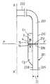
도1a는 안정한 개방 위치에서 종래 기술의 얇은 측부를 갖는 안경테의 텔레스코픽 관절식 영역의 평면도이다.1A is a plan view of a telescopic articulated region of a spectacle frame having a thin side of the prior art in a stable open position.
도1b는 불안정한 넓은 개방 위치에서 도1a와 같은 동일한 관절식 영역의 평면도이다.Figure 1B is a plan view of the same articulated region as in Figure 1A in an unstable wide open position.
도2a는 안정한 개방 위치에서 종래 기술의 두꺼운 측부를 갖는 안경테의 텔레스코픽 관절식 영역의 평면도이다.2A is a plan view of a telescopic articulated region of a spectacle frame with thick sides of the prior art in a stable open position.
도2b는 불안정한 넓은 개방 위치에서 도2a와 같은 동일한 관절식 영역의 평면도이다.FIG. 2B is a top view of the same articulated region as in FIG. 2A in an unstable wide open position.
도3a는 안정한 개방 위치에서 본 발명의 제1 실시예에 따른 두꺼운 측부를 갖는 안경테의 텔레스코픽 관절식 영역의 평면도이다.3A is a plan view of a telescopic articulated region of a spectacle frame having a thick side in accordance with a first embodiment of the present invention in a stable open position;
도3b는 불안정한 넓은 개방 위치에서 도3a와 같은 동일한 관절식 영역의 평면도이다.3B is a top view of the same articulated region as in FIG. 3A in an unstable wide open position.
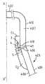
도4a는 안정한 개방 위치에서 본 발명의 제2 실시예에 따른 두꺼운 측부를 갖는 안경테의 텔레스코픽 관절식 영역의 평면도이다.4A is a plan view of a telescopic articulated region of a spectacle frame with a thick side in accordance with a second embodiment of the present invention in a stable open position;
도4b는 불안정한 넓은 개방 위치에서 도4a와 같은 동일한 관절식 영역의 평면도이다.4B is a top view of the same articulated region as in FIG. 4A in an unstable wide open position.
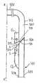
도5a는 안정한 개방 위치에서 본 발명의 제3 실시예에 따른 두꺼운 측부를 갖는 텔레스코픽 관절식 영역의 평면도이다.5A is a plan view of a telescopic articulated region with thick sides in accordance with a third embodiment of the present invention in a stable open position;
도5b는 불안정한 넓은 개방 위치에서 도5a와 같은 동일한 관절식 영역의 평면도이다.FIG. 5B is a top view of the same articulated region as in FIG. 5A in an unstable wide open position. FIG.
도1은 종래 기술의 안경테의 두 개의 얇은 측부(101) 중 한 부분을 도시하고, 피벗 지점(3), 타이-로드(4) 및 복원 스프링(5)이 텔레스코픽 힌지부(C1, C2)에 의해 관절식으로 연결되는 안경테 면(102) 부분이 개략적으로 도시된다. 측부(101)는 "선단부"인 힌지 측 단부(106)를 포함하고, 힌지측 단부는 안경테 면(102)의 스텁(107) 형성 부분의 "선단부"인 힌지 측 단부(113)에 평행하게 가까이 근접한다. 선단부(106 및 113)는 마주보는 영역 또는 접합 영역(Z1)을 갖는다. 마찬가지로 관절부(C1 및 C2)는 서로 마주보는 선단부(15 및 16)를 갖는다. 접합 영역(Z1)은 관절부의 선단면(15 및 16)과 측부(101) 및 스텁(107) 각각의 선단부(106 및 113) 사이를 통과하는 접합면(P, P')에 놓인다. 측부(101)는 내부면(108) 및 외부면(109)을 갖는다. 도1a에서, 측부(101)는 안정한 개방 위치에 있고, 측부의 외부면(109)은 스텁(107)의 외부면(110)과 정렬한다.Figure 1 shows one part of two
도1b는 도1a와 같은 동일한 안경테 부분을 도시하지만, 이러한 경우에 안경테 부분은 스프링(5)의 힘에 반대하여 접합 영역(Z1)의 외부 에지에 위치된 지지점(111)에 대하여 피벗됨으로써 불안정한 넓은 개방 위치로 이동되었다. 이러한 위치에서, 측부(101)의 외부면(109)은 안경테 면(102)의 스텁(107)의 외부면(110)과 2 내지 8°사이의 각도(α)를 이룬다.FIG. 1B shows the same eyeglass frame portion as in FIG. 1A, but in this case the eyeglass frame portion is unstable wide by pivoting against a support point 111 located at the outer edge of the bonding zone Z1 against the force of the
도2a 및 도2b에서, 도1a 및 도1b와 동일한 요소는 동일한 도면 부호로 나타나고, 수정되었지만 유사한 역할을 하는 요소는 도1a 및 도1b에 도시된 도면 부호보다 100만큼 증가되었으며, 면(202) 및 측부(201)가 두꺼운 것만 도1a 및 도1b와 다르다.In Figures 2A and 2B, the same elements as in Figures 1A and 1B are denoted by the same reference numerals, and elements modified but acting similarly have been increased by 100 than those shown in Figures 1A and 1B,
따라서, 도2a 및 도2b와 비교하여 알 수 있는 바와 같이, 접합 영역(Z2)은 영역(Z1)보다 두껍고, 따라서 지지점(211)과 힌지부의 피벗 지점(3) 사이의 거리는 얇은 측부(101)의 경우에서보다 두꺼운 측부(201)의 경우에서 눈에 띄게 크게 된다. 그 결과, 동일한 각도의 넓은 개방에서 두꺼운 측부(201)의 경우에는 타이-로드(4)의 더욱 긴 길이가 밖으로 당겨져야 하고, 이는 스프링(5)이 더욱 압축되어야 함을 의미한다. 따라서 스프링은 더욱 큰 복원력을 발휘하여, 착용자를 불편하게 한다.Thus, as can be seen in comparison with FIGS. 2A and 2B, the junction region Z2 is thicker than the region Z1, so that the distance between the
도3a 및 도3b에서, 도1a 및 도1b와 같은 동일한 요소는 동일한 도면 부호로 나타나고, 수정되었지만 유사한 역할을 하는 요소는 도1a 및 도1b에 도시된 도면 부호보다 200만큼 증가되었으며, 스텁(307)의 선단부(313)가 모따기 가공(12) 된 것만 도2a 및 도2b와 다르다. 이러한 모따기 가공(12)에 의해, 접합 영역(Z3)은 접합 영역(Z1)의 두께에 근접한 두께로 감소되어, 지지점(311)은 동일한 측부 두께의 경우에 도2b에서보다 피벗 지점(3)에 근접하게 된다. 사실상, 이는 얇은 측부(101)를 도시하는 도1b의 경우에서와 같이 피벗 지점(3)으로부터 동일한 거리가 될 것이다.In Figures 3A and 3B, the same elements, such as Figures 1A and 1B, are represented by the same reference numerals, and the elements that have been modified but serve a similar role have been increased by 200 than the reference numerals shown in Figures 1A and 1B, and the
도4a 및 도4b에서, 도1a 및 도1b와 같은 동일한 요소는 동일한 도면 부호로 나타나고, 수정되었지만 유사한 역할을 하는 요소는 도1a 및 도1b에 도시된 도면 부호보다 300만큼 증가되었으며, 본 발명의 제2 실시예에 따른 안경테의 두개의 측부(401) 중 하나를 도시한다. 이때, 측부(401)의 선단부(406)와 스텁(407)의 선단 부(413) 사이에 간극(14)이 존재하게 된다. 접합 영역(Z4)은 두께가 0이 되어, 지지점(411)은 힌지 접합부의 관절부(C1 및 C2)의 대향 단부면(15 및 16) 영역의 외부 에지와 일치한다. 이러한 간극(14)에 의해, 지지점(411)은 두꺼운 측부를 갖는 안경테일지라도 도1a 및 도1b의 얇은 측부의 경우에서보다 더욱 근접하게 되기 때문에 피벗 지점(3)에 가능한 한 근접하게 된다.In Figures 4A and 4B, the same elements as in Figures 1A and 1B are represented by the same reference numerals, and the elements that have been modified but serve a similar role have been increased by 300 than those shown in Figures 1A and 1B, One of the two
도5a 및 도5b에서, 도1a 및 도1b와 같은 동일한 요소는 동일한 도면 부호로 나타나고, 수정되었지만 유사한 역할을 하는 요소는 도1a 및 도1b에 도시된 도면 부호보다 400만큼 증가되었으며, 본 발명의 제3 실시예에 따른 안경테의 두 개의 측부(501) 중 하나를 도시한다. 불안정한 넓은 개방 위치에서의 상기의 수행 모드와는 달리, 측부(501)의 외부면(509) 및 스텁(507)의 외부면(510)은 안경이 착용되는 위치인 불안정한 넓은 개방 위치에서 정렬된다. 이러한 모양을 달성하기 위해, 측부(501)의 선단부(506) 및 스텁(507)의 선단부(513)에서 또한 힌지부(C1', C2')의 대향 단부면(515 및 516)에서 변화가 이루어졌다. 특히, 안정한 개방 상태(도5a)에서 이러한 단부(506, 513, 515, 516)는 비스듬하게 되고, 측부(501)의 외부면(509)은 스텁(507)의 외부면(510)의 평면에 대해 안쪽으로 굽은 각도(α)를 형성한다. 이러한 특정 배열을 제외하고는, 도5a 및 도5b의 실시예는 접합 영역(Z5)이 도면 부호 512에서 스텁(507)의 모따기 가공으로 인해 더욱 얇게 된다는 점에서 도3a 및 도3b의 실시예와 같은 동일한 형태이다. 따라서, 지지점(511)은 피벗 지점에 더 근접하게 된다.In Figures 5A and 5B, the same elements as in Figures 1A and 1B are represented by the same reference numerals, and the elements that have been modified but serve a similar role have been increased by 400 than those shown in Figures 1A and 1B, One of the two
물론, 본 발명은 기술되고 도시된 실시예에 제한되는 것은 아니다. 따라서, 예를 들면, 모따기 가공(12 또는 512)은 스텁의 선단부에 형성되는 대신에 측부의 선단부에 형성될 수 있다. 또한, 모따기 가공 이외의 임의의 형태로 구성된 리세스 역시 가능하다.Of course, the invention is not limited to the described and illustrated embodiments. Thus, for example, chamfering 12 or 512 can be formed at the tip of the side instead of at the tip of the stub. In addition, a recess formed in any shape other than chamfering is also possible.
Claims (8)
Translated fromKoreanApplications Claiming Priority (2)
| Application Number | Priority Date | Filing Date | Title |
|---|---|---|---|
| FR03/07454 | 2003-06-20 | ||
| FR0307454AFR2856483B1 (en) | 2003-06-20 | 2003-06-20 | MOUNT GLASSES OPENING AROUND A SUPPORTING POINT |
Publications (2)
| Publication Number | Publication Date |
|---|---|
| KR20050037601A KR20050037601A (en) | 2005-04-22 |
| KR100720625B1true KR100720625B1 (en) | 2007-05-23 |
Family
ID=33484592
Family Applications (1)
| Application Number | Title | Priority Date | Filing Date |
|---|---|---|---|
| KR1020057003962AExpired - Fee RelatedKR100720625B1 (en) | 2003-06-20 | 2004-06-16 | Spectacle Frame Comprising Arms Which Can Be Opended Out Wide Around an Offset Support Point |
Country Status (18)
| Country | Link |
|---|---|
| US (1) | US7073904B2 (en) |
| EP (1) | EP1636632B1 (en) |
| JP (1) | JP2006511849A (en) |
| KR (1) | KR100720625B1 (en) |
| CN (1) | CN100350299C (en) |
| AT (1) | ATE547736T1 (en) |
| AU (1) | AU2004250350A1 (en) |
| BR (1) | BRPI0411696A (en) |
| CA (1) | CA2497563A1 (en) |
| DE (1) | DE202004020564U1 (en) |
| ES (1) | ES2382738T3 (en) |
| FR (1) | FR2856483B1 (en) |
| HK (1) | HK1062791A2 (en) |
| JO (1) | JO2393B1 (en) |
| MY (1) | MY134436A (en) |
| RU (1) | RU2006102668A (en) |
| TW (1) | TWI262334B (en) |
| WO (1) | WO2004113996A1 (en) |
Families Citing this family (8)
| Publication number | Priority date | Publication date | Assignee | Title |
|---|---|---|---|---|
| US7637609B1 (en)* | 2006-02-24 | 2009-12-29 | Chic Optic, Inc. | Resilient hinge for eyeglasses |
| US7380935B2 (en)* | 2006-09-12 | 2008-06-03 | Chic Optic, Inc. | Mechanical universal hinge |
| US8226227B2 (en)* | 2009-09-18 | 2012-07-24 | Sony Corporation | Glasses for image viewing |
| FR2950706B1 (en)* | 2009-09-29 | 2011-11-11 | Logo | ELASTICALLY ARTICULATED BRACELET GLASSES |
| FR2988492B1 (en)* | 2012-03-21 | 2016-10-28 | Dominique Delamour | TELESCOPIC HINGE FOR EYEWEAR MOUNT |
| CN204422890U (en)* | 2015-02-04 | 2015-06-24 | 景新(香港)有限公司 | An elastic hinge for glasses |
| US12216341B2 (en)* | 2018-06-28 | 2025-02-04 | Lucyd Ltd. | Wireless smartglasses with quick connect front frames |
| CN116068788A (en)* | 2021-10-29 | 2023-05-05 | 富泰京精密电子(烟台)有限公司 | Rotating shaft structure and terminal product |
Citations (1)
| Publication number | Priority date | Publication date | Assignee | Title |
|---|---|---|---|---|
| FR2816072A1 (en)* | 2000-10-26 | 2002-05-03 | Frederic Beausoleil | Spectacle frame spring-loaded hinge has spring tension adjuster in form of screw in closed end of sleeve containing spring and rod |
Family Cites Families (8)
| Publication number | Priority date | Publication date | Assignee | Title |
|---|---|---|---|---|
| US3549246A (en)* | 1966-12-20 | 1970-12-22 | Rivo Sa | Spring biased spectacle temples |
| CH635444A5 (en)* | 1980-03-26 | 1983-03-31 | Nationale Sa | GLASSES HINGE. |
| IT8430853U1 (en)* | 1984-09-25 | 1986-03-25 | Visottica Spa | ELASTIC HINGE FOR GLASSES. |
| CH668492A5 (en)* | 1986-10-22 | 1988-12-30 | Nationale Sa | FRAME OF ELASTIC HINGE GLASSES. |
| DE4008086A1 (en)* | 1989-11-04 | 1991-09-19 | Obe Werk Kg | SPRING HINGE FOR EYEWEAR |
| IT1262254B (en)* | 1993-12-17 | 1996-06-19 | Euroframes Srl | HINGE FOR CONNECTION BETWEEN BAR AND FRAME IN A PAIR OF GLASSES |
| EP0889347A1 (en)* | 1997-07-04 | 1999-01-07 | Italiana Aste S.r.l. | Improvement in a hinge structure in particular for spectacles |
| IT245534Y1 (en)* | 1998-10-09 | 2002-03-22 | Ideal Srl | AUCTION-FLEX PERFECTED FOR EYEWEAR, OF THE TYPE WITH ELASTIC BALL DECK MECHANISM. |
- 2003
- 2003-06-20FRFR0307454Apatent/FR2856483B1/ennot_activeExpired - Lifetime
- 2004
- 2004-06-07TWTW093116304Apatent/TWI262334B/ennot_activeIP Right Cessation
- 2004-06-09HKHK04104139Apatent/HK1062791A2/ennot_activeIP Right Cessation
- 2004-06-11MYMYPI20042263Apatent/MY134436A/enunknown
- 2004-06-16CACA002497563Apatent/CA2497563A1/ennot_activeAbandoned
- 2004-06-16RURU2006102668/28Apatent/RU2006102668A/enunknown
- 2004-06-16CNCNB2004800009195Apatent/CN100350299C/ennot_activeExpired - Fee Related
- 2004-06-16ESES04767352Tpatent/ES2382738T3/ennot_activeExpired - Lifetime
- 2004-06-16WOPCT/FR2004/001489patent/WO2004113996A1/enactiveApplication Filing
- 2004-06-16USUS10/527,808patent/US7073904B2/ennot_activeExpired - Lifetime
- 2004-06-16AUAU2004250350Apatent/AU2004250350A1/ennot_activeAbandoned
- 2004-06-16KRKR1020057003962Apatent/KR100720625B1/ennot_activeExpired - Fee Related
- 2004-06-16BRBRPI0411696-8Apatent/BRPI0411696A/ennot_activeApplication Discontinuation
- 2004-06-16ATAT04767352Tpatent/ATE547736T1/enactive
- 2004-06-16DEDE202004020564Upatent/DE202004020564U1/ennot_activeExpired - Lifetime
- 2004-06-16EPEP04767352Apatent/EP1636632B1/ennot_activeExpired - Lifetime
- 2004-06-16JPJP2005518164Apatent/JP2006511849A/enactivePending
- 2007
- 2007-02-25JOJO200478Apatent/JO2393B1/enactive
Patent Citations (1)
| Publication number | Priority date | Publication date | Assignee | Title |
|---|---|---|---|---|
| FR2816072A1 (en)* | 2000-10-26 | 2002-05-03 | Frederic Beausoleil | Spectacle frame spring-loaded hinge has spring tension adjuster in form of screw in closed end of sleeve containing spring and rod |
Also Published As
| Publication number | Publication date |
|---|---|
| WO2004113996A1 (en) | 2004-12-29 |
| DE202004020564U1 (en) | 2005-09-08 |
| AU2004250350A1 (en) | 2004-12-29 |
| EP1636632A1 (en) | 2006-03-22 |
| FR2856483A1 (en) | 2004-12-24 |
| TW200500684A (en) | 2005-01-01 |
| HK1085543A1 (en) | 2006-08-25 |
| HK1062791A2 (en) | 2004-11-05 |
| ATE547736T1 (en) | 2012-03-15 |
| RU2006102668A (en) | 2007-07-27 |
| JO2393B1 (en) | 2007-06-17 |
| CN100350299C (en) | 2007-11-21 |
| US7073904B2 (en) | 2006-07-11 |
| KR20050037601A (en) | 2005-04-22 |
| TWI262334B (en) | 2006-09-21 |
| ES2382738T3 (en) | 2012-06-13 |
| WO2004113996A8 (en) | 2005-03-31 |
| JP2006511849A (en) | 2006-04-06 |
| CA2497563A1 (en) | 2004-12-29 |
| CN1701257A (en) | 2005-11-23 |
| FR2856483B1 (en) | 2005-09-02 |
| US20060050226A1 (en) | 2006-03-09 |
| EP1636632B1 (en) | 2012-02-29 |
| MY134436A (en) | 2007-12-31 |
| BRPI0411696A (en) | 2006-10-17 |
Similar Documents
| Publication | Publication Date | Title |
|---|---|---|
| KR100720625B1 (en) | Spectacle Frame Comprising Arms Which Can Be Opended Out Wide Around an Offset Support Point | |
| JPH10133153A (en) | Temple joint structure of spectacle frame | |
| AU2022288072A1 (en) | Side shield for eyeglasses | |
| CA2141896C (en) | Folding frameless eyeglasses | |
| KR102211699B1 (en) | Jointing structure of temple for spectacle frame | |
| CN101984768A (en) | Stable positions for spectacles hinges | |
| US4354744A (en) | Frame for eyeglasses | |
| JPS59188619A (en) | Spectacles frame with elastic hinge mechanism | |
| US3841741A (en) | Eyeglass frame | |
| JPH11295663A (en) | Hinge for glasses | |
| JPH1039261A (en) | Folding mechanism of hingeless spectacle temples | |
| JP3814615B2 (en) | Eyeglass frames | |
| US4018516A (en) | Spectacle frame | |
| CN209803471U (en) | Glasses leg and glasses | |
| CN112596267A (en) | Elastic alloy glasses frame | |
| MXPA05014058A (en) | Spectacle frame comprising arms which can be opened out wide around an offset support point | |
| HK1085543B (en) | Spectacle frame comprising arms which can be opened out wide around an offset support point | |
| JP4830192B2 (en) | Hinge | |
| JP2621017B2 (en) | Eyeglass frame hinge mechanism | |
| JPH11326844A (en) | Bending joint structure for eyeglass frames | |
| JP3050814U (en) | Glasses frame | |
| JPH032896Y2 (en) | ||
| JPS6020099Y2 (en) | eyeglass frames | |
| JPS6020098Y2 (en) | eyeglass frame | |
| JPH0472207B2 (en) |
Legal Events
| Date | Code | Title | Description |
|---|---|---|---|
| A201 | Request for examination | ||
| PA0105 | International application | St.27 status event code:A-0-1-A10-A15-nap-PA0105 | |
| PA0201 | Request for examination | St.27 status event code:A-1-2-D10-D11-exm-PA0201 | |
| PG1501 | Laying open of application | St.27 status event code:A-1-1-Q10-Q12-nap-PG1501 | |
| E902 | Notification of reason for refusal | ||
| PE0902 | Notice of grounds for rejection | St.27 status event code:A-1-2-D10-D21-exm-PE0902 | |
| P11-X000 | Amendment of application requested | St.27 status event code:A-2-2-P10-P11-nap-X000 | |
| P13-X000 | Application amended | St.27 status event code:A-2-2-P10-P13-nap-X000 | |
| E701 | Decision to grant or registration of patent right | ||
| PE0701 | Decision of registration | St.27 status event code:A-1-2-D10-D22-exm-PE0701 | |
| GRNT | Written decision to grant | ||
| PR0701 | Registration of establishment | St.27 status event code:A-2-4-F10-F11-exm-PR0701 | |
| PR1002 | Payment of registration fee | St.27 status event code:A-2-2-U10-U12-oth-PR1002 Fee payment year number:1 | |
| PG1601 | Publication of registration | St.27 status event code:A-4-4-Q10-Q13-nap-PG1601 | |
| PR1001 | Payment of annual fee | St.27 status event code:A-4-4-U10-U11-oth-PR1001 Fee payment year number:4 | |
| PR1001 | Payment of annual fee | St.27 status event code:A-4-4-U10-U11-oth-PR1001 Fee payment year number:5 | |
| PR1001 | Payment of annual fee | St.27 status event code:A-4-4-U10-U11-oth-PR1001 Fee payment year number:6 | |
| FPAY | Annual fee payment | Payment date:20130515 Year of fee payment:7 | |
| PR1001 | Payment of annual fee | St.27 status event code:A-4-4-U10-U11-oth-PR1001 Fee payment year number:7 | |
| FPAY | Annual fee payment | Payment date:20140423 Year of fee payment:8 | |
| PR1001 | Payment of annual fee | St.27 status event code:A-4-4-U10-U11-oth-PR1001 Fee payment year number:8 | |
| FPAY | Annual fee payment | Payment date:20150429 Year of fee payment:9 | |
| PR1001 | Payment of annual fee | St.27 status event code:A-4-4-U10-U11-oth-PR1001 Fee payment year number:9 | |
| FPAY | Annual fee payment | Payment date:20160502 Year of fee payment:10 | |
| PR1001 | Payment of annual fee | St.27 status event code:A-4-4-U10-U11-oth-PR1001 Fee payment year number:10 | |
| P22-X000 | Classification modified | St.27 status event code:A-4-4-P10-P22-nap-X000 | |
| FPAY | Annual fee payment | Payment date:20170519 Year of fee payment:11 | |
| PR1001 | Payment of annual fee | St.27 status event code:A-4-4-U10-U11-oth-PR1001 Fee payment year number:11 | |
| PN2301 | Change of applicant | St.27 status event code:A-5-5-R10-R11-asn-PN2301 | |
| PN2301 | Change of applicant | St.27 status event code:A-5-5-R10-R14-asn-PN2301 | |
| FPAY | Annual fee payment | Payment date:20180504 Year of fee payment:12 | |
| PR1001 | Payment of annual fee | St.27 status event code:A-4-4-U10-U11-oth-PR1001 Fee payment year number:12 | |
| P22-X000 | Classification modified | St.27 status event code:A-4-4-P10-P22-nap-X000 | |
| PR1001 | Payment of annual fee | St.27 status event code:A-4-4-U10-U11-oth-PR1001 Fee payment year number:13 | |
| PR1001 | Payment of annual fee | St.27 status event code:A-4-4-U10-U11-oth-PR1001 Fee payment year number:14 | |
| PC1903 | Unpaid annual fee | St.27 status event code:A-4-4-U10-U13-oth-PC1903 Not in force date:20210516 Payment event data comment text:Termination Category : DEFAULT_OF_REGISTRATION_FEE | |
| PC1903 | Unpaid annual fee | St.27 status event code:N-4-6-H10-H13-oth-PC1903 Ip right cessation event data comment text:Termination Category : DEFAULT_OF_REGISTRATION_FEE Not in force date:20210516 | |
| R18-X000 | Changes to party contact information recorded | St.27 status event code:A-5-5-R10-R18-oth-X000 |