KR100717018B1 - Defective nozzle detection method of inkjet image forming apparatus and inkjet image forming apparatus - Google Patents
Defective nozzle detection method of inkjet image forming apparatus and inkjet image forming apparatusDownload PDFInfo
- Publication number
- KR100717018B1 KR100717018B1KR1020050071693AKR20050071693AKR100717018B1KR 100717018 B1KR100717018 B1KR 100717018B1KR 1020050071693 AKR1020050071693 AKR 1020050071693AKR 20050071693 AKR20050071693 AKR 20050071693AKR 100717018 B1KR100717018 B1KR 100717018B1
- Authority
- KR
- South Korea
- Prior art keywords
- nozzle
- detecting
- unit
- bad
- Prior art date
- Legal status (The legal status is an assumption and is not a legal conclusion. Google has not performed a legal analysis and makes no representation as to the accuracy of the status listed.)
- Expired - Fee Related
Links
Images


Classifications
- B—PERFORMING OPERATIONS; TRANSPORTING
- B41—PRINTING; LINING MACHINES; TYPEWRITERS; STAMPS
- B41J—TYPEWRITERS; SELECTIVE PRINTING MECHANISMS, i.e. MECHANISMS PRINTING OTHERWISE THAN FROM A FORME; CORRECTION OF TYPOGRAPHICAL ERRORS
- B41J29/00—Details of, or accessories for, typewriters or selective printing mechanisms not otherwise provided for
- B41J29/38—Drives, motors, controls or automatic cut-off devices for the entire printing mechanism
- B41J29/393—Devices for controlling or analysing the entire machine ; Controlling or analysing mechanical parameters involving printing of test patterns
- B—PERFORMING OPERATIONS; TRANSPORTING
- B41—PRINTING; LINING MACHINES; TYPEWRITERS; STAMPS
- B41J—TYPEWRITERS; SELECTIVE PRINTING MECHANISMS, i.e. MECHANISMS PRINTING OTHERWISE THAN FROM A FORME; CORRECTION OF TYPOGRAPHICAL ERRORS
- B41J2/00—Typewriters or selective printing mechanisms characterised by the printing or marking process for which they are designed
- B41J2/005—Typewriters or selective printing mechanisms characterised by the printing or marking process for which they are designed characterised by bringing liquid or particles selectively into contact with a printing material
- B41J2/01—Ink jet
- B41J2/015—Ink jet characterised by the jet generation process
- B41J2/04—Ink jet characterised by the jet generation process generating single droplets or particles on demand
- B41J2/045—Ink jet characterised by the jet generation process generating single droplets or particles on demand by pressure, e.g. electromechanical transducers
- B41J2/04501—Control methods or devices therefor, e.g. driver circuits, control circuits
- B41J2/0451—Control methods or devices therefor, e.g. driver circuits, control circuits for detecting failure, e.g. clogging, malfunctioning actuator
- B—PERFORMING OPERATIONS; TRANSPORTING
- B41—PRINTING; LINING MACHINES; TYPEWRITERS; STAMPS
- B41J—TYPEWRITERS; SELECTIVE PRINTING MECHANISMS, i.e. MECHANISMS PRINTING OTHERWISE THAN FROM A FORME; CORRECTION OF TYPOGRAPHICAL ERRORS
- B41J2/00—Typewriters or selective printing mechanisms characterised by the printing or marking process for which they are designed
- B41J2/005—Typewriters or selective printing mechanisms characterised by the printing or marking process for which they are designed characterised by bringing liquid or particles selectively into contact with a printing material
- B41J2/01—Ink jet
- B41J2/07—Ink jet characterised by jet control
- B41J2/125—Sensors, e.g. deflection sensors
- B—PERFORMING OPERATIONS; TRANSPORTING
- B41—PRINTING; LINING MACHINES; TYPEWRITERS; STAMPS
- B41J—TYPEWRITERS; SELECTIVE PRINTING MECHANISMS, i.e. MECHANISMS PRINTING OTHERWISE THAN FROM A FORME; CORRECTION OF TYPOGRAPHICAL ERRORS
- B41J2/00—Typewriters or selective printing mechanisms characterised by the printing or marking process for which they are designed
- B41J2/005—Typewriters or selective printing mechanisms characterised by the printing or marking process for which they are designed characterised by bringing liquid or particles selectively into contact with a printing material
- B41J2/01—Ink jet
- B41J2/135—Nozzles
- B41J2/165—Prevention or detection of nozzle clogging, e.g. cleaning, capping or moistening for nozzles
- B41J2/16579—Detection means therefor, e.g. for nozzle clogging
- B—PERFORMING OPERATIONS; TRANSPORTING
- B41—PRINTING; LINING MACHINES; TYPEWRITERS; STAMPS
- B41J—TYPEWRITERS; SELECTIVE PRINTING MECHANISMS, i.e. MECHANISMS PRINTING OTHERWISE THAN FROM A FORME; CORRECTION OF TYPOGRAPHICAL ERRORS
- B41J2/00—Typewriters or selective printing mechanisms characterised by the printing or marking process for which they are designed
- B41J2/005—Typewriters or selective printing mechanisms characterised by the printing or marking process for which they are designed characterised by bringing liquid or particles selectively into contact with a printing material
- B41J2/01—Ink jet
- B41J2/21—Ink jet for multi-colour printing
- B41J2/2132—Print quality control characterised by dot disposition, e.g. for reducing white stripes or banding
- B41J2/2142—Detection of malfunctioning nozzles
Landscapes
- Engineering & Computer Science (AREA)
- Quality & Reliability (AREA)
- Ink Jet (AREA)
Abstract
Translated fromKoreanDescription
Translated fromKorean도 1은 본 발명에 따른 잉크젯 화상형성장치의 일 실시예를 개략적으로 보여주는 도면이다.1 is a view schematically showing an embodiment of an inkjet image forming apparatus according to the present invention.
도 2는 본 발명에 따른 검출수단의 일 실시예를 보여주는 도면이다.2 is a view showing an embodiment of the detection means according to the present invention.
도 3은 본 발명에 따른 검출수단의 다른 실시예를 도시한 사시도이다.3 is a perspective view showing another embodiment of the detection means according to the present invention.
도 4는 도 3의 검출수단을 도시한 측단면도이다.4 is a side sectional view showing the detection means of FIG.
도 5는 본 발명에 따른 프린트 헤드의 일 실시예를 도시한 평면도이다.5 is a plan view showing an embodiment of a print head according to the present invention.
도 6은 본 발명에 따른 프린트 헤드의 구동 메카니즘을 보여주는 도면이다.Figure 6 shows the drive mechanism of the print head according to the invention.
도 7은 본 발명에 따른 화상형성시스템을 보여주는 블록도이다.7 is a block diagram illustrating an image forming system according to the present invention.
도 8은 본 발명에 따른 잉크젯 화상형성장치의 구성을 보여주는 블록도이다.8 is a block diagram showing a configuration of an inkjet image forming apparatus according to the present invention.
도 9는 본 발명에 따른 잉크젯 화상형성장치의 불량 노즐 검출 방법을 보여주는 흐름도(flow chart)이다.9 is a flowchart illustrating a method for detecting a bad nozzle of an inkjet image forming apparatus according to the present invention.
도 10은 본 발명에 따른 제1시험 인쇄 패턴을 보여주는 도면이다.10 is a view showing a first test print pattern according to the present invention.
도 11은 도 10의 블랙 인쇄 패턴의 일부분을 확대한 도면이다.FIG. 11 is an enlarged view of a portion of the black print pattern of FIG. 10.
도 12는 제1시험 인쇄 패턴으로부터 불량 노즐이 속한 그룹을 검출하는 방법을 설명하기 위한 도면이다.12 is a view for explaining a method of detecting a group to which a defective nozzle belongs from the first test print pattern.
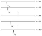
도 13은 본 발명에 따른 제2시험 인쇄 패턴을 보여주는 도면이다.13 is a view showing a second test print pattern according to the present invention.
도 14는 제2시험 인쇄 패턴으로부터 불량 노즐 위치를 검출하는 방법을 설명하기 위한 도면이다.It is a figure for demonstrating the method of detecting the bad nozzle position from a 2nd test printing pattern.
<도면의 주요부분에 대한 부호의 설명><Description of the symbols for the main parts of the drawings>
105..........프린트 헤드 유니트 106..........캐리지105 .......... Print
110..........몸체 111..........프린트 헤드110 ..........
112..........노즐부 113, 115, 116, 117.......인쇄매체 이송부112 ........ Nozzle
114..........지지부재 130..........제어부114 ........
132..........검출수단 160..........구동수단132 ........ Detection means 160 .......... Drive means
165..........메인티넌스부165 .......... Maintenance department
T1C, T1M, T1Y, T1K.......제1시험 인쇄 패턴T1C, T1M, T1Y, T1K ......... Test Print Pattern
T2C, T2M, T2Y, T2K.......제2시험 인쇄 패턴T2C, T2M, T2Y, T2K ....... Second Test Print Pattern
본 발명은 잉크젯 화상형성장치에 관한 것으로서, 보다 상세하게는 불량 노즐 발생시 이를 정확하고 용이하게 검출할 수 있는 잉크젯 화상형성장치(Ink jet image forming apparatus) 및 불량 노즐 검출 방법(Method for detecting defect nozzle)에 관한 것이다.The present invention relates to an inkjet image forming apparatus, and more particularly, an ink jet image forming apparatus and a method for detecting defect nozzle, which can accurately and easily detect when a defective nozzle occurs. It is about.
일반적으로, 잉크젯 화상형성장치는 인쇄매체의 이송방향과 직각방향으로 왕 복 주행되는 프린트 헤드로부터 잉크를 분사하여 화상을 형성하는 장치를 말한다. 이와 같이 인쇄매체의 이송방향과 직각방향으로 이송되면서 인쇄매체에 잉크를 분사하여 화상을 형성하는 화상형성장치를 셔틀 방식 잉크젯 화상형성장치라 한다. 이러한 셔틀 방식 잉크젯 화상형성장치의 프린트 헤드에는 잉크를 분사하는 복수의 노즐이 형성된 노즐부가 마련되어 있다.In general, an inkjet image forming apparatus refers to an apparatus for forming an image by ejecting ink from a printhead reciprocated in a direction perpendicular to a conveying direction of a print medium. The image forming apparatus which forms an image by spraying ink onto the printing medium while being transferred in a direction perpendicular to the conveying direction of the printing medium is called a shuttle type inkjet image forming apparatus. The print head of the shuttle-type inkjet image forming apparatus is provided with a nozzle portion having a plurality of nozzles for ejecting ink.
근래에는 사용자들의 고속 인쇄 요구를 만족시키기 위해 인쇄매체의 폭에 해당되는 길이의 노즐부를 갖는 프린트 헤드를 사용하여 고속 인쇄를 구현하려는 시도가 행하여지고 있다. 이와 같은 방식으로 작동되는 화상형성장치를 라인 프린팅 방식 잉크젯 화상형성장치라 한다.In recent years, attempts have been made to implement high speed printing by using a print head having a nozzle portion having a length corresponding to a width of a print medium in order to satisfy a high speed printing demand of users. The image forming apparatus operated in this manner is called a line printing inkjet image forming apparatus.
일반적으로, 라인 프린팅 방식 잉크젯 화상형성장치의 프린트 헤드는 고정되어 있고, 인쇄매체만이 이송된다. 즉, 프린트 헤드가 고정된 상태에서 인쇄매체만이 이송되며 인쇄가 이루어지므로, 프린트 헤드에 구비된 각각의 노즐들은 인쇄매체의 이송방향에 대해 일대일 대응관계를 이루게 된다. 노즐부 중 어느 하나의 노즐이 손상되면 인쇄매체에는 흰 선(white line)과 같은 미싱 라인(missing line)이 나타난다. 따라서, 불량 노즐을 보상하기 위해 불량 노즐의 위치를 정확하게 검출하는 것이 매우 중요하다.In general, the print head of the line printing type inkjet image forming apparatus is fixed, and only the print medium is conveyed. That is, since only the print medium is transferred and printing is performed while the print head is fixed, each nozzle provided in the print head has a one-to-one correspondence with respect to the print direction of the print medium. If any of the nozzles is damaged, a missing line, such as a white line, appears on the print medium. Therefore, it is very important to accurately detect the position of the defective nozzle to compensate for the defective nozzle.
셔틀 방식의 경우 노즐부의 노즐 수가 많지 않으므로 시험 인쇄(test page printing)를 통해 불량 노즐을 검출할 수 있다. 그러나, 라인 프린팅 방식의 경우 노즐부의 노즐 수가 너무 많으므로 불량 노즐의 정확한 위치를 검출하기가 쉽지 않다. 또한, 불량 노즐의 정확한 위치 검출을 위해 검출수단으로 고정밀 스캐너가 필 요하게 된다. 고정밀 스캐너를 사용할 경우 잉크젯 화상형성장치의 제조 원가가 상승된다. 또한, 고정밀 스캐너를 사용하더라도 노즐열이 길고, 각 노즐 간의 간격이 매우 좁으므로, 스큐(skew) 등과 같은 물리적인 오차로 인해 불량 노즐의 정확한 위치를 검출하기가 난이하다. 따라서, 불량 노즐의 정확한 위치를 검출할 필요성이 요청된다.In the case of the shuttle method, since the number of nozzles in the nozzle unit is not large, a defective nozzle may be detected through test page printing. However, in the case of the line printing method, since the number of nozzles in the nozzle part is too large, it is difficult to detect the exact position of the defective nozzle. In addition, a high-precision scanner is required as a detection means for accurate position detection of a defective nozzle. The use of high precision scanners increases the manufacturing cost of the inkjet image forming apparatus. In addition, even when a high-precision scanner is used, the nozzle array is long and the interval between the nozzles is very narrow, which makes it difficult to detect the exact position of the defective nozzle due to physical errors such as skew. Thus, a need exists to detect the exact position of a bad nozzle.
본 발명은 상기한 바와 같은 문제점을 개선하기 위해 창출된 것으로서, 저가의 검출수단을 이용하여 불량 노즐을 정확하게 검출할 수 있는 잉크젯 화상형성장치 및 불량 노즐 검출 방법을 제공하는데 그 목적이 있다. 또한, 본 발명은 불량 노즐 검출시 상기 불량 노즐을 회복시킬 수 있는 잉크젯 화상형성장치 및 불량 노즐 검출 방법을 제공하는데 그 목적이 있다.An object of the present invention is to provide an inkjet image forming apparatus and a bad nozzle detecting method capable of accurately detecting a bad nozzle using a low-cost detecting means, which have been created to improve the above problems. Another object of the present invention is to provide an inkjet image forming apparatus and a bad nozzle detecting method capable of recovering the bad nozzle when a bad nozzle is detected.
본 발명에 따른 잉크젯 화상형성장치는: 인쇄매체의 폭에 해당되는 길이의 노즐부를 갖는 프린트 헤드; 상기 프린트 헤드를 구동시켜 상기 인쇄매체에 화상을 인쇄하는 구동수단; 상기 노즐부를 소정 개수의 그룹으로 분할한 후 불량 노즐이 발생된 그룹을 검출하기 위한 제1시험 인쇄 패턴과, 상기 그룹에서 상기 불량 노즐이 몇 번째 위치되었는지를 검출하기 위한 제2시험 인쇄 패턴을 인쇄하도록 상기 구동수단의 동작을 제어하는 제어신호를 생성하는 제어부; 및 상기 제1, 제2시험 인쇄 패턴으로부터 상기 노즐부의 불량 노즐 발생 위치를 검출하는 검출수단;을 구비하는 것을 특징으로 한다.An inkjet image forming apparatus according to the present invention comprises: a print head having a nozzle portion having a length corresponding to a width of a print medium; Driving means for driving the print head to print an image on the print medium; After dividing the nozzle portion into a predetermined number of groups, a first test print pattern for detecting a group in which a bad nozzle is generated and a second test print pattern for detecting how many times the bad nozzle is located in the group are printed. A control unit for generating a control signal for controlling the operation of the driving means; And detecting means for detecting a defective nozzle occurrence position of the nozzle part from the first and second test print patterns.
일 실시예로서, 상기 제어부는, 상기 검출수단이 상기 각 그룹의 위치를 검출하도록, 상기 제1시험 인쇄 패턴이 각 그룹의 위치를 나타내는 참조 표시(reference indication)를 포함하도록 인쇄하는 것을 특징으로 한다. 여기서, 상기 참조 표시는 상기 인쇄매체의 폭방향으로 소정 간격 이격되며, 상기 인쇄매체의 이송방향으로 선 모양인 것을 특징으로 한다.In one embodiment, the control unit prints the first test print pattern to include a reference indication indicating the position of each group, so that the detecting means detects the position of each group. . Here, the reference mark is spaced apart a predetermined interval in the width direction of the print medium, it characterized in that the line shape in the conveying direction of the print medium.
일 실시예로서, 상기 제어부는, 상기 검출수단이 상기 그룹에서 상기 불량 노즐이 몇 번째 위치되었는지를 검출하도록, 상기 불량 노즐이 속한 상기 그룹의 첫 번째 노즐부터 소정 시간 간격으로 상기 노즐들을 순차적으로 구동시켜 상기 제2시험 인쇄 패턴을 인쇄하는 것을 특징으로 한다.In one embodiment, the control unit sequentially drives the nozzles at predetermined time intervals from the first nozzle of the group to which the defective nozzle belongs so that the detection means detects the position of the defective nozzle in the group. The second test print pattern is printed.
일 실시예로서, 상기 검출수단은, 상기 인쇄매체에 광을 주사하는 발광부와, 상기 인쇄매체로부터 반사되는 광을 수광하는 수광부를 구비하는 것을 특징으로 한다.In one embodiment, the detecting means includes a light emitting part for scanning light onto the print medium and a light receiving part for receiving light reflected from the print medium.
일 실시예로서, 상기 검출수단은, 상기 노즐부를 통과하면서 잉크가 분사된 상기 인쇄매체에 광을 주사하고 이로부터 반사되는 광을 검출하여 상기 인쇄매체로부터 불량 노즐에 대한 정보를 읽어들이는 독취부;를 구비하는 것을 특징으로 한다. 여기서, 상기 독취부는, 케이스; 및 상기 케이스의 내부에 설치되는 것으로, 광원으로부터 소정 간격 이격되게 설치되어 상기 광원에서 출사된 광을 상기 인쇄매체로 반사시키는 반사부와, 상기 인쇄매체로부터 반사된 광을 소정의 경로로 반사시키는 미러부와, 상기 미러부에서 반사된 광의 광경로 상에 위치하는 렌즈부와, 상기 렌즈부를 통과한 광을 검출하여 상기 인쇄매체로부터 불량 노즐에 대한 정보 를 읽어들이는 독취수단;을 구비하는 것을 특징으로 한다. 또한, 상기 미러부는 하나의 미러를 구비하는 것을 특징으로 한다. 상기 검출수단은, 불량 노즐 검출력을 높이기 위해 상기 제1, 제2시험 인쇄 패턴에 보색광을 주사하는 것을 특징으로 한다.In one embodiment, the detection unit, the reading unit for scanning the light to the printing medium, the ink is injected while passing through the nozzle unit and detects the light reflected therefrom to read information about the defective nozzle from the printing medium It is characterized by including; Here, the reading unit, the case; And a reflection part installed inside the case and spaced apart from the light source by a predetermined distance to reflect the light emitted from the light source to the print medium, and a mirror to reflect the light reflected from the print medium through a predetermined path. And a lens unit positioned on an optical path of the light reflected from the mirror unit, and reading means for detecting the light passing through the lens unit and reading information on the bad nozzle from the print medium. It is done. In addition, the mirror unit is characterized in that it comprises a mirror. The detection means is characterized by scanning complementary light on the first and second test print patterns in order to increase the defective nozzle detection force.
본 발명에 따른 불량 노즐 검출 방법은: 인쇄매체의 폭에 해당되는 길이의 노즐부를 갖는 프린트 헤드를 구비하는 잉크젯 화상형성장치에 있어서, (a) 불량 노즐이 발생된 그룹을 검출하기 위한 제1시험 인쇄 패턴을 인쇄하는 단계; (b) 검출수단에 의해 상기 제1시험 인쇄 패턴으로부터 상기 불량 노즐이 발생된 그룹을 검출하는 단계; (c) 상기 불량 노즐이 발생된 그룹에서 상기 불량 노즐이 몇 번째 위치되었는지를 검출하기 위한 제2시험 인쇄 패턴을 인쇄하는 단계; 및 (d) 상기 검출수단에 의해 상기 제2시험 인쇄 패턴으로부터 상기 불량 노즐이 발생된 위치를 검출하는 단계;를 포함하는 것을 특징으로 한다.A method for detecting a bad nozzle according to the present invention includes: an inkjet image forming apparatus having a print head having a nozzle portion having a length corresponding to a width of a print medium, the method comprising: (a) a first test for detecting a group in which a bad nozzle is generated; Printing a print pattern; (b) detecting, by detection means, a group in which the bad nozzle is generated from the first test print pattern; (c) printing a second test print pattern for detecting how many times the defective nozzle is located in the group in which the defective nozzle is generated; And (d) detecting a position at which the defective nozzle is generated from the second test print pattern by the detecting means.
일 실시예로서, 상기 (a) 단계는, 상기 검출수단이 상기 각 그룹의 위치를 검출하도록, 상기 제1시험 인쇄 패턴이 각 그룹의 위치를 나타내는 참조 표시(reference indication)를 포함하도록 인쇄하는 것을 특징으로 한다. 여기서, 상기 참조 표시는 상기 인쇄매체의 폭방향으로 소정 간격 이격되며, 상기 인쇄매체의 이송방향으로 선 모양인 것을 특징으로 한다.In one embodiment, the step (a) may be performed such that the first test print pattern includes a reference indication indicating the position of each group, so that the detecting means detects the position of each group. It features. Here, the reference mark is spaced apart a predetermined interval in the width direction of the print medium, it characterized in that the line shape in the conveying direction of the print medium.
일 실시예로서, 상기 (c) 단계는, 상기 검출수단이 상기 그룹에서 상기 불량 노즐이 몇 번째 위치되었는지를 검출하도록, 상기 불량 노즐이 속한 상기 그룹의 첫 번째 노즐부터 소정 시간 간격으로 상기 노즐들을 순차적으로 구동시켜 상기 제 2시험 인쇄 패턴을 인쇄하는 것을 특징으로 한다.In an embodiment, the step (c) may include the nozzles at predetermined time intervals from the first nozzle of the group to which the defective nozzle belongs, so that the detecting means detects the position of the defective nozzle in the group. It is characterized in that for driving sequentially to print the second test print pattern.
일 실시예로서, 상기 검출수단은, 상기 인쇄매체에 광을 주사하는 발광부와, 상기 인쇄매체로부터 반사되는 광을 수광하는 수광부를 구비하는 것을 특징으로 한다.In one embodiment, the detecting means includes a light emitting part for scanning light onto the print medium and a light receiving part for receiving light reflected from the print medium.
일 실시예로서, 상기 검출수단은, 상기 노즐부를 통과하면서 잉크가 분사된 상기 인쇄매체에 광을 주사하고 이로부터 반사되는 광을 검출하여 상기 인쇄매체로부터 불량 노즐에 대한 정보를 읽어들이는 독취부;를 구비하는 것을 특징으로 한다. 여기서, 상기 독취부는, 케이스; 및 상기 케이스의 내부에 설치되는 것으로, 광원으로부터 소정 간격 이격되게 설치되어 상기 광원에서 출사된 광을 상기 인쇄매체로 반사시키는 반사부와, 상기 인쇄매체로부터 반사된 광을 소정의 경로로 반사시키는 미러부와, 상기 미러부에서 반사된 광의 광경로 상에 위치하는 렌즈부와, 상기 렌즈부를 통과한 광을 검출하여 상기 인쇄매체로부터 불량 노즐에 대한 정보를 읽어들이는 독취수단;을 구비하는 것을 특징으로 한다. 또한, 상기 검출수단은, 불량 노즐 검출력을 높이기 위해 상기 제1, 제2시험 인쇄 패턴에 보색광을 주사하는 것을 특징으로 한다.In one embodiment, the detection unit, the reading unit for scanning the light to the printing medium, the ink is injected while passing through the nozzle unit and detects the light reflected therefrom to read information about the defective nozzle from the printing medium It is characterized by including; Here, the reading unit, the case; And a reflection part installed inside the case and spaced apart from the light source by a predetermined distance to reflect the light emitted from the light source to the print medium, and a mirror to reflect the light reflected from the print medium through a predetermined path. And a lens unit positioned on an optical path of the light reflected from the mirror unit, and reading means for detecting the light passing through the lens unit and reading information on the defective nozzle from the print medium. It is done. In addition, the detection means is characterized by scanning the complementary light to the first, second test printing pattern in order to increase the bad nozzle detection force.
일 실시예로서, 상기 (b) 단계는, 노이즈에 의한 검출 오차를 최소화하기 위해 상기 제1시험 인쇄 패턴을 n회 반복하여 검출하고, 검출된 값이 문턱 전압(threshold level) 이상인 횟수에 따라 상기 불량 노즐이 발생된 그룹을 검출하는 것을 특징으로 한다. 여기서, 불량 노즐 검출 방법은, 상기 문턱 전압을 조절하여 상기 불량 노즐 검출 성능을 향상시키는 것을 특징으로 한다.In an embodiment, the step (b) may be performed by repeatedly detecting the first test print pattern n times in order to minimize the detection error caused by noise, and according to the number of times the detected value is equal to or greater than a threshold level. And detecting a group in which a bad nozzle is generated. Here, the bad nozzle detection method is characterized by improving the bad nozzle detection performance by adjusting the threshold voltage.
일 실시예로서, 상기 불량 노즐이 발생된 위치를 검출한 후 상기 불량 노즐에 대하여 인쇄 대기 상태로 회복시키기 위한 회복(maintenance) 동작을 실시하는 단계;를 더 포함하는 것을 특징으로 한다.In an embodiment, the method may further include performing a maintenance operation for restoring to the printing standby state with respect to the defective nozzle after detecting the position where the defective nozzle is generated.
이하, 첨부된 도면들을 참조하여 본 발명에 따른 잉크젯 화상형성장치 및 잉크젯 화상형성장치의 불량 노즐 검출 방법을 상세히 설명한다. 설명의 빠른 이해를 위해 잉크젯 화상형성장치의 전체적인 구성을 먼저 설명한 후, 잉크젯 화상형성장치의 불량 노즐 보상 방법을 설명한다. 이 과정에서 도면에 도시된 선들의 두께나 구성요소의 크기 등은 설명의 명료성과 편의상 과장되게 도시되어 있을 수 있다. 또한, 후술되는 용어들은 본 발명에서의 기능을 고려하여 정의된 용어들로서 이는 사용자, 운용자의 의도 또는 관례에 따라 달라질 수 있다. 그러므로, 이러한 용어들에 대한 정의는 본 명세서 전반에 걸친 내용을 토대로 내려져야 할 것이다.Hereinafter, a bad nozzle detection method of an inkjet image forming apparatus and an inkjet image forming apparatus according to the present invention will be described in detail with reference to the accompanying drawings. The overall configuration of the inkjet image forming apparatus will be described first for a quick understanding of the description, and then a bad nozzle compensation method of the inkjet image forming apparatus will be described. In this process, the thickness of the lines or the size of the components shown in the drawings may be exaggerated for clarity and convenience of description. In addition, terms to be described below are terms defined in consideration of functions in the present invention, which may vary according to the intention or convention of a user or an operator. Therefore, definitions of these terms should be made based on the contents throughout the specification.
도 1은 본 발명에 따른 잉크젯 화상형성장치의 일 실시예를 개략적으로 보여주는 도면이다.1 is a view schematically showing an embodiment of an inkjet image forming apparatus according to the present invention.
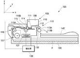
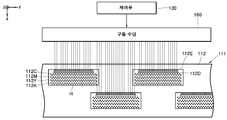
도 1을 참조하면, 잉크젯 화상형성장치(125)는 급지카세트(120)와, 프린트 헤드 유니트(105)와, 이와 대면되게 위치되는 지지부재(114)와, 노즐부(112)의 불량 노즐 발생 여부를 감지하는 검출수단(132)과, 인쇄매체(P)를 제1방향(x 방향)으로 이송시키는 인쇄매체 이송부(117, 116, 115, 113), 및 인쇄매체(P)가 배지 후 적재되는 적재부(140)를 구비한다. 또한, 잉크젯 화상형성장치(125)는 각각의 구성요소의 동작을 제어하는 제어부(130)를 구비한다.Referring to FIG. 1, the inkjet
인쇄매체(P)는 급지카세트(120)에 적재된다. 급지카세트(120)에 적재된 인쇄 매체(P)는 후술하는 인쇄매체 이송부(117, 116, 115, 113)에 의해 프린트 헤드(111)를 지나 적재부(140)로 이송된다. 여기서, 적재부(140)는 배지 트레이(tray)와 같이 화상이 형성된 인쇄매체(P)가 배지 후 적재되는 부분을 의미한다.The print medium P is loaded in the
인쇄매체 이송부(117, 116, 115, 113)는 급지카세트(120)에 적재된 인쇄매체(P)를 소정의 경로를 따라 이송시키는 것으로, 본 실시예에서는 픽업롤러(117)와, 보조롤러(116)와, 피딩롤러(115), 및 배지롤러(113)를 구비한다. 인쇄매체 이송부(117, 116, 115, 113)는 모터와 같은 구동원(131)에 의해 구동되며, 인쇄매체(P)를 이송시키는 이송력을 제공한다. 상기 구동원(131)의 동작은 후술하는 제어부(130)에 의해 제어된다. 즉, 제어부(130)는 구동원(131)의 동작을 제어하여 인쇄매체(P)의 이송속도를 결정한다.The print
픽업롤러(117)는 급지카세트(120)의 일측에 설치되며, 급지카세트(120)에 적재된 인쇄매체(P)를 한 장씩 픽업하여 인출한다. 피딩롤러(115)는 프린트 헤드(111)의 입측에 설치되며, 픽업롤러(117)에 의해 인출된 인쇄매체(P)를 프린트 헤드(111)로 이송시킨다. 피딩롤러(115)는 인쇄매체(P)를 이송시키는 이송력을 제공하는 구동롤러(driving roller, 115A)와, 이에 탄력적으로 맞물리는 종동롤러(idle roller, 115B)를 포함한다. 픽업롤러(117)와 피딩롤러(115) 사이에는 인쇄매체(P)를 이송시키는 한 쌍의 보조롤러(116)가 더 설치될 수 있다. 배지롤러(113)는 프린트 헤드(111)의 출측에 설치되며, 인쇄가 완료된 인쇄매체(P)를 화상형성장치(125)의 밖으로 배지시킨다. 화상형성장치(125)에서 배지된 인쇄매체(P)는 적재부(140)에 적재된다.The
일 실시예로서, 배지롤러(113)는 인쇄매체(P)의 폭방향으로 나란하게 설치되는 스타휠(113A)과, 이에 대면되어 인쇄매체(P)의 배면을 지지하는 지지롤러(113B)를 구비한다. 노즐부(112)를 통과하면서 그 상면에 잉크가 분사된 인쇄매체(P)는 잉크에 의하여 젖어서 웨이브가 생길 수 있다. 또한, 웨이브로 인해 인쇄매체(P)와 노즐부(112)와의 간격이 유지되지 않을 가능성이 매우 높다. 스타휠(113A)은 노즐부(112)의 하방으로 이송되는 인쇄매체(P)가 노즐부(112) 또는 몸체(110)의 저면에 접촉되거나 인쇄매체(P)와 노즐부(112)와의 간격이 변하는 것을 방지하기 위한 것으로서, 적어도 일부분은 노즐부(112)보다 더 돌출되도록 설치되어 인쇄매체(P)의 상면에 점접촉된다.In one embodiment, the
지지부재(114)는 노즐부(112)와 인쇄매체(P)가 소정의 간격을 유지하도록 프린트 헤드(111)의 하측에 마련되어 이송되는 인쇄매체(P)의 배면을 지지한다. 노즐부(112)와 인쇄매체(P)와의 간격은 약 0.5 ∼ 2.5 mm 정도이다.The
검출수단(132)은 제조 공정 상에서 발생된 불량 노즐이나, 인쇄 작업을 수행하는 중 발생되는 노즐부(112)의 불량 노즐 발생 여부를 검출한다. 불량 노즐(defect nozzle)이란 잉크를 분사하지 못하는 손상된 노즐(dead nozzle)이나 기능이 약화된 노즐(weak nozzle)과 같이, 잉크를 정상적으로 분사하지 못하는 노즐을 의미한다. 즉, 불량 노즐(defect nozzle)은 여러 가지 원인으로 인해 노즐에서 잉크가 분사되지 않거나, 설계 사양보다 작은 잉크 액적량이 분사되는 노즐을 의미한다. 이와 같은 불량 노즐은 프린트 헤드(111)의 제조 공정이나, 인쇄 작업을 수행하는 중 발생될 수 있다. 일반적으로, 제조 공정상에서 발생된 불량 노즐에 대한 정보는 프린트 헤드(111)에 구비된 메모리(미도시)에 별도로 기억되며, 이와 같은 정보는 프린트 헤드(111)를 화상형성장치(125)에 장착시 화상형성장치(125)로 전달된다.The detection means 132 detects whether or not a defective nozzle generated in the manufacturing process or the
잉크젯 화상형성장치의 프린트 헤드는 잉크 액적(ink droplet)에 분사력을 제공하는 구동수단의 종류에 따라 크게 열구동 방식과 압전구동 방식으로 분류된다. 열구동 방식으로 잉크를 분사하는 경우, 잉크를 분사시키는 데 작용되는 히터(heater)가 단선되거나 히터의 구동회로가 고장나는 경우, 또는 FET(Field Emission Transistor)가 고장나는 경우와 같이, 전기적인 구성 요소의 손상에 의해 발생되는 노즐의 불량은 쉽게 감지될 수 있다. 마찬가지로, 압전구동 방식으로 잉크를 분사하는 경우, 압전소자 자체의 불량이나 압전소자를 구동하는 구동회로의 손상에 의해 발생되는 노즐의 불량도 쉽게 감지될 수 있다.The print head of the inkjet image forming apparatus is classified into a heat driving method and a piezoelectric driving method according to the type of driving means for providing injection force to ink droplets. In the case of spraying ink by a thermal drive method, electrical configuration such as when a heater acting to eject ink is broken or a driving circuit of the heater is broken, or a field emission transistor (FET) is broken. Failure of the nozzle caused by damage to the element can be easily detected. Similarly, when the ink is ejected by the piezoelectric drive method, the failure of the nozzle caused by the failure of the piezoelectric element itself or the driving circuit for driving the piezoelectric element can be easily detected.
상기와 달리, 이물질이나 찌꺼기 등에 의해 노즐이 막히는 경우와 같이, 불량 노즐의 발생 원인을 쉽게 감지할 수 없는 경우도 있다. 불량 노즐이 발생된 원인을 쉽게 감지할 수 없는 경우 시험 인쇄(test page printing)를 실시하여 불량 노즐을 검출한다. 불량 노즐(defect nozzle)이 발생되면 불량 노즐에 의해 인쇄되는 부분의 인쇄 농도는 손실 도트(missing dot)로 인해 정상적인 노즐에 의해 인쇄되는 부분의 인쇄 농도보다 낮다. 검출수단(132)은 시험 인쇄시 정상 노즐에 의해 인쇄되는 영역과 불량 노즐에 의해 인쇄되는 영역 사이에는 농도 차이를 이용하여 불량 노즐을 검출하게 된다.Unlike the above, in some cases, such as when the nozzle is clogged by foreign matter or debris, it may not be possible to easily detect the cause of the defective nozzle. If the cause of the defective nozzle cannot be easily detected, test page printing is performed to detect the defective nozzle. If a defective nozzle occurs, the print density of the portion printed by the defective nozzle is lower than the print density of the portion printed by the normal nozzle due to the missing dot. The detection means 132 detects the defective nozzle by using the difference in concentration between the area printed by the normal nozzle and the area printed by the bad nozzle during test printing.
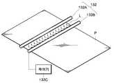
도 2는 본 발명에 따른 검출수단의 일 실시예를 보여주는 도면이다.2 is a view showing an embodiment of the detection means according to the present invention.
도 2를 참조하면, 검출수단(132)은 인쇄매체(P)에 광(L)을 주사하는 발광부(132A)와, 인쇄매체(P)로부터 반사되는 광(L)을 수광하는 수광부(132B)를 구비한다. 검출수단(132)은 인쇄매체(P)로부터 반사되는 광(L)량의 차이를 감지하여 불량 노즐 발생 위치를 검출한다. 검출수단(132)은 인쇄매체(P)의 폭방향으로 설치되는 것이 바람직하다. 발광부(132A)로부터 인쇄매체(P)로 광(L)이 출사되고, 수광부(132B)에는 인쇄매체(P)에서 반사된 광(L)이 수광된다. 즉, 발광부(132A)에서 출사된 광(L)은 인쇄매체(P)에 반사되어 수광부(132B)로 유입된다. 이때, 불량 노즐이 발생되면, 수광부(132B)로 유입되는 광량의 변화가 있게 되므로, 이에 의해 불량 노즐의 발생 위치를 검출하게 된다. 발광부(132A)와 수광부(132B)의 일 예로 빛을 발하는 광원(예를 들어, 발광 다이오드(light emitting diode)과, 그 빛을 받아들이는 포토센서를 들 수 있다.Referring to FIG. 2, the
검출수단(132)은 제어기(132C)를 더 구비할 수 있다. 제어기(132C)는 수광부(132B)로부터 출력되는 센싱 전류를 미리 결정된 특정치와 비교, 판단하여 불량 노즐 발생 위치에 대한 정보 신호를 생성한다. 검출수단(132)은 제어기(132C)로부터 발생되는 신호(signal)를 받아 불량 노즐의 위치를 검출하게 된다.The detecting means 132 may further include a
상술한 바와 같이, 검출수단(132)에 의해 검출된 불량 노즐의 위치에 대한 정보는 별도의 메모리(미도시)에 저장된 후, 후술하는 제어부(130)로 전달된다.As described above, the information on the position of the defective nozzle detected by the detection means 132 is stored in a separate memory (not shown), and then transferred to the
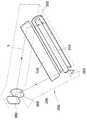
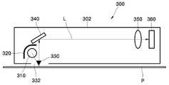
도 3은 본 발명에 따른 검출수단의 다른 실시예를 도시한 사시도이고, 도 4는 도 3의 검출수단을 도시한 측단면도이다.3 is a perspective view showing another embodiment of the detection means according to the invention, Figure 4 is a side cross-sectional view showing the detection means of FIG.
도 3, 도 4, 및 도 1을 참조하면, 검출수단(132)은 노즐부(112)를 통과하면 서 잉크가 분사된 인쇄매체(P)에 광을 주사하고 인쇄매체(P)로부터 반사되는 광을 검출하여 인쇄매체(P)로부터 불량 노즐에 대한 정보를 읽어들이는 독취부(300)를 구비한다.3, 4, and 1, the
독취부(300)는 노즐부(112)와 배지롤러(113) 사이에 설치되며, 노즐부(112)를 통과한 인쇄매체(P)의 상면에 광을 주사하여 이로부터 반사되는 광량을 검출하고, 이 광량을 전기적인 신호로 바꿈으로써 인쇄매체(P)로부터 불량 노즐에 대한 정보를 읽어들이게 된다. 상기 독취부(300)는 외장을 구성하는 케이스(302)와, 상기 케이스(302)의 내부에 설치되는 것으로 광원(310)과, 반사부(320)와, 미러부(340)와, 렌즈부(350), 및 독취수단(360)을 구비한다.The
광원(310)은 인쇄매체(P)를 스캐닝하기 위한 광(L)이 출사되는 것으로, 본 실시예에서는 CCF(cold cathode fluorescent) 램프(Lamp)를 사용하였다. 반사부(reflector, 320)는 광원(310)으로부터 소정 간격 이격되게 설치되어 광원(310)에서 출사된 광을 인쇄매체(P)로 반사시킨다.The
리딩홀(reading hall, 332)은 광원(310)에서 출사된 광(L)과 반사부(320)로부터 반사된 광(L)이 소정의 방향으로 이송되는 인쇄매체(P)의 인쇄면과 만나는 부위에 형성된다. 리딩포인트(reading point, 330)는 인쇄매체(P)의 인쇄면에 대한 정보가 읽혀지는 부분으로 리딩홀(332)의 영역 내에 형성된다.The
미러부(340)는 리딩홀(332)을 통과하는 인쇄매체(P)로부터 반사되는 반사광(L)을 후술하는 렌즈부(350)로 반사시킨다. 독취부(300)의 두께를 줄이기 위해 상기 미러부(340)는 하나의 미러를 구비하는 것이 바람직하다.The
렌즈부(350)는 상기 미러부(340)로부터 반사된 반사광(L)의 광경로 상에 배치되는 것으로, 상기 렌즈부(350)를 통과한 광은 독취수단(360)으로 입사된다. 독취수단(360)은 인쇄매체(P)의 인쇄면으로부터 반사되어 상기 렌즈부(350)를 통과한 광량을 검출하고, 이 광량을 전기적인 신호로 바꿈으로써 불량 노즐 발생 여부에 대한 정보를 읽어들이게 된다. 독취수단(360)으로는 심도(depth of focus)가 뛰어난 CCD(charge coupled device)가 채용되는 것이 바람직하다. 또는, 독취수단(360)으로 CIS(contact image sensor)가 사용될 수도 있다. CIS와 CCD는 본 발명이 속하는 기술 분야의 당업자에게 널리 알려져 있으므로, 이에 대한 상세한 설명은 생략한다. 또한, 독취수단은 CIS나 CCD 이외의 다른 형태의 독취수단이 적용될 수도 있다.The
또한, 도 3에 도시된 바와 같이 독취부(300)의 외관을 이루는 케이스(302)는 삼각형의 형상을 갖는 평판 형태인 것이 바람직하다. 광원(310)과 반사부(320)와 미러부(340)는 삼각형 형상의 밑변부에 위치되며, 삼각형 형상의 꼭지점에 해당하는 위치에는 렌즈부(350)와 독취수단(360)이 위치된다. 상기와 같이 독취부(300)를 구성함으로써 검출수단(132)을 소형화할 수 있다.In addition, as shown in FIG. 3, the
검출수단(132)의 또 다른 실시예로서, 프린트 헤드(111)의 각 노즐에 노즐 체크 신호를 전송하여 신호의 응답 여부에 따라 불량 노즐 발생 위치를 자동으로 검출할 수 있다.As another embodiment of the detection means 132, a nozzle check signal may be transmitted to each nozzle of the
검출수단(132)는 상술한 바와 같은 일련의 프로세스에 의해 불량 노즐의 발생 위치를 검출하게 된다. 검출수단(132)에 의해 검출된 불량 노즐에 대한 정보는 메모리(미도시)에 저장되며, 제어부(130)는 상기 메모리(미도시)에 저장된 불량 노즐 정보에 따라 각 구성요소의 동작을 제어하게 된다.The detection means 132 detects the occurrence position of the defective nozzle by a series of processes as described above. Information about the defective nozzles detected by the detection means 132 is stored in a memory (not shown), and the
다시 도 1을 참조하면, 프린트 헤드 유니트(105)는 인쇄매체(P)에 잉크를 분사하여 화상을 인쇄한다. 프린트 헤드 유니트(105)는 몸체(110)와, 몸체(110)의 일측에 마련되는 프린트 헤드(111)와, 프린트 헤드(111)에 구비되는 노즐부(112), 및 상기 몸체(110)가 장착되는 캐리지(106)를 구비한다. 캐리지(106)에는 몸체(110)가 카트리지 형태로 장착된다. 노즐부(112)의 입측에는 피딩롤러(115)가, 출측에는 배지롤러(113)가 회전 가능하게 설치된다.Referring back to FIG. 1, the
도면으로 첨부되지는 않았지만, 몸체(110)에는 잉크가 수용되는 카트리지 형태의 잉크 저장 공간이 착탈 가능하게 설치된다. 또한, 몸체(110)에는 노즐부(112)의 각 노즐들과 연통되고 잉크를 분사하기 위한 압력을 제공하는 구동수단(예를 들면, 압전 방식의 압전(피에조)소자, 열구동 방식의 히터)이 마련된 챔버와, 몸체(110)에 수용된 잉크를 챔버로 공급하기 위한 유로(예를 들면, 오리피스(orifice)), 유로를 통해 유입된 잉크를 챔버로 공급하는 공통 유로인 매니폴드와, 매니폴드로부터 각각의 챔버로 잉크를 공급하기 위한 개별 유로인 리스트릭터 등이 더 구비될 수 있다. 챔버, 유로, 매니폴드, 리스트릭터 등은 본 발명이 속하는 기술분야의 당업자에게 잘 알려져 있으므로 이에 대한 상세한 설명은 생략한다. 한편, 잉크가 수용되는 잉크 저장 공간은 프린트 헤드 유니트(105)와 별도로 설치될 수도 있다. 이와 같이 별도로 설치된 잉크 저장 공간(미도시)에 수용된 잉크는 호스와 같은 이동수단을 통해 프린트 헤드 유니트(105)로 공급된다.Although not attached to the drawings, the ink storage space of the cartridge type in which the ink is accommodated is detachably installed in the
도 5는 본 발명에 따른 프린트 헤드의 일 실시예를 도시한 평면도이고, 도 6은 본 발명에 따른 프린트 헤드의 구동 메카니즘을 보여주는 도면이다. 이하, 설명의 편의를 위해 구성 및 작용이 동일한 구성요소에 대해서는 동일한 참조번호로 인용하였다.5 is a plan view showing an embodiment of a print head according to the present invention, and FIG. 6 is a view showing a driving mechanism of the print head according to the present invention. Hereinafter, for the convenience of description, the same reference numerals are used for components having the same configuration and operation.
도 5 및 도 1을 참조하면, 프린트 헤드(111)는 제1방향(x 방향)으로 이송되는 인쇄매체(P)에 대해 제2방향(y 방향)으로 설치된다. 상기 프린트 헤드(111)는 열에너지와 압전소자 등을 잉크 분사 동력원으로 사용하며, 에칭, 증착, 스퍼터링 등의 반도체 제조 공정에 의하여 고해상도를 가지도록 제조된다. 프린트 헤드(111)에는 이송되는 인쇄매체(P)에 잉크를 분사하여 화상을 형성하는 노즐부(112)가 구비된다. 노즐부(112)는 인쇄매체(P)의 폭에 해당되는 길이를 갖거나, 인쇄매체(P)의 폭보다 길게 형성되는 것이 바람직하다.5 and 1, the
도 6 및 도 1을 참조하면, 구동수단(160)은 잉크 액적(ink droplet)을 분사시키는 분사력(firing force)을 제공하는 것으로, 소정의 주파수(frequency)로 프린트 헤드(111)를 구동시켜 인쇄매체(P)에 화상을 인쇄한다. 구동수단(160)은 잉크 액적(ink droplet)에 분사력(firing force)을 제공하는 액츄에이터의 종류에 따라 크게 두 가지 방식으로 분류된다. 그 하나는 히터(heater)를 이용하여 잉크에 버블(bubble)을 발생시켜 그 버블의 팽창력에 의해 잉크 액적을 분사시키는 열구동 방식이고, 다른 하나는 압전소자를 사용하여 그 압전소자의 변형으로 인해 잉크에 가해지는 압력에 의해 잉크 액적을 분사시키는 압전소자 방식이다. 여기서, 노즐부(112)의 각 노즐들을 구동시키는 구동수단(160)의 구동 동작은 후술하는 제어부 (130)에 의해 제어된다.6 and 1, the driving means 160 provides a firing force for ejecting ink droplets. The driving means 160 prints by driving the
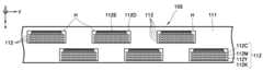
상술한 바와 같이 프린트 헤드(111)에는 화상을 인쇄하는 노즐부(112)가 구비된다. 노즐부(112)는 헤드 칩(head chip)(H) 형태로 프린트 헤드(111)에 장착될 수도 있고, 라인 형태로 프린트 헤드(111)에 장착될 수도 있다. 또한, 노즐부(112)의 노즐열(nozzle array)은 길이 방향으로 하나의 라인 형태로 배열될 수도 있고, 서로 엇갈리게 배치되는 두 개의 라인 형태로 배열될 수도 있다. 이하, 첨부된 도면을 참조하여 프린트 헤드(111) 및 노즐부(112)의 구성을 설명한다.As described above, the
일 실시예로서, 도 5에 도시된 바와 같이, 프린트 헤드(111)에는 다수의 노즐열(112C, 112M, 112Y, 112K)이 형성된 다수의 헤드 칩(head chip)(H)이 장착된다. 각 헤드 칩(H)에는 각 노즐들을 선택적으로 구동시키거나 각 노즐들을 그룹 단위로 시분할 구동시키는 구동회로(112D)가 마련된다. 다수의 헤드 칩(H)이 일렬로 배열되면, 경계 부분인 헤드 칩(H) 사이의 노즐 간격이 동일한 헤드 칩(H) 내에서의 노즐 간격보다 더 이격되어 인쇄매체(P) 상에 잉크가 분사되지 않는 영역이 발생될 수 있다. 따라서, 상기 다수의 헤드 칩(H)은 도시된 바와 같이 제2방향(y 방향)으로 지그재그(zigzag)로 배치되는 것이 바람직하다.As an example, as shown in FIG. 5, the
또한, 각 헤드 칩(H)의 노즐열(112C, 112M, 112Y, 112K) 중 동일한 색상의 잉크를 분사하는 노즐열은 제2방향(y 방향)으로의 해상도를 향상시키기 위해 서로 엇갈리게 배치되는 것이 바람직하다. 상기와 같이 노즐열(112C, 112M, 112Y, 112K)을 엇갈리게 배열하면 각 노즐열의 노즐에서 분사되는 잉크 도트가 다른 노즐열의 노즐에서 분사되는 잉크 도트의 사이에 착탄되어 제2방향(y 방향)으로의 해상도를 향상시킬 수 있다.In addition, nozzle rows for injecting ink of the same color among the
또한, 노즐부(112)에 구비된 각 노즐들에는 후술하는 제어부(130)에 의한 구동 신호와 잉크 분사를 위한 전력, 화상 데이터 등이 전달되는 구동회로(112D)와 케이블(112E)이 연결된다. 케이블(112E)로는 FPC(Flexible Printed Circuit)나, FFC(Flexible Flat Cable)와 같은 유연한 케이블이 사용되는 것이 바람직하다.In addition, each of the nozzles provided in the
본 실시예에서는 헤드 칩(H)을 갖는 프린트 헤드(111)를 예로 들어 설명하였으나, 본 발명의 프린트 헤드(111)는 다양한 형태로 구성될 수 있다. 예를 들어, 프린트 헤드는 인쇄매체의 폭에 해당되는 길이에 상응하는 하나의 헤드 칩으로 제조될 수 있다. 또는, 프린트 헤드에는 인쇄매체의 폭에 해당되는 길이의 노즐열이 제2방향으로 배열될 수도 있다. 즉, 도시된 프린트 헤드(111)는 본 발명의 일 실시예일 뿐이며, 첨부된 도면에 의하여 본 발명의 기술적 범위가 제한되는 것은 아니다.In the present embodiment, the
도 7은 본 발명에 따른 화상형성시스템을 보여주는 블록도이고, 도 8은 본 발명에 따른 잉크젯 화상형성장치의 구성을 보여주는 블록도이다. 여기서, 화상형성시스템은 호스트인 데이터 입력부(135)와 잉크젯 화상형성장치(125)를 포함한다.7 is a block diagram showing an image forming system according to the present invention, and FIG. 8 is a block diagram showing the configuration of an inkjet image forming apparatus according to the present invention. Here, the image forming system includes a
도 7을 참조하면, 데이터 입력부(135)는 PC(Personal Computer), 디지털 카메라, 또는 PDA(Personal Digital Assistant)와 같은 호스트(host) 시스템을 의미하며, 인쇄하고자 하는 화상 데이터를 인쇄 페이지 순서대로 입력받는다. 데이터 입력부(135)는 응용 프로그램(210), 그래픽스 디바이스 인터페이스(GDI; graphics device interface)(220), 화상형성장치 드라이버(230), 사용자 인터페이스(240), 및 스풀러(250)를 포함한다.Referring to FIG. 7, the
응용프로그램(210)은 화상형성장치(125)를 이용하여 출력이 가능한 오브젝트(object)를 생성하고 편집하는 기능을 한다. GDI(220)는 호스트 상의 운영체제에 존재하는 프로그램으로서, 응용프로그램(210)에서 생성된 오브젝트를 받아 화상형성장치 드라이버(230)에 전달하며, 화상형성장치 드라이버(230)가 요청하는 오브젝트에 관한 명령어를 생성한다. 화상형성장치 드라이버(230)는 컴퓨터 상에 존재하는 프로그램으로서 화상형성장치(125)가 해석할 수 있는 명령어를 생성한다. 화상형성장치 드라이버(230)를 위한 사용자 인터페이스(240)는 컴퓨터 상에 존재하는 프로그램으로 화상형성장치 드라이버(230)가 명령어를 생성하는 환경변수를 제공한다. 스풀러(Spooler)(250)는 호스트 상의 운영체제에 존재하는 프로그램으로서 화상형성장치 드라이버(230)가 생성한 명령어를 화상형성장치(125)와 연결된 물리적인 입출력장치(미도시)에 전달한다.The
화상형성장치(125)는 비디오 컨트롤러(170), 제어부(130), 및 인쇄 환경 정보부(136)를 포함한다. 또한, 비디오 컨트롤러(170)는 비휘발성 메모리(NVRAM; non-volatile random access memory)(185), SRAM(미도시), SDRAM(미도시), NOR Flash(미도시), 및 실시간 클럭(RTC; real time clock)(190)을 포함한다. 상기 비디오 컨트롤러(170)는 화상형성장치 드라이버(230)가 생성한 명령어를 해석하여 비트맵(bitmap)화 한 후, 제어부(130)로 전달한다. 상기 제어부(130)는 비디오 컨트롤러(170)가 생성한 비트맵을 화상형성장치(125)의 각 구성요소로 전달하여 인쇄매체(P)에 화상이 형성되게 한다. 상술한 바와 같은 과정을 통해 화상형성장치(125) 에서 인쇄가 수행된다.The
도 8 및 도 7을 참조하면, 제어부(130)는 잉크젯 화상형성장치(125)의 마더보드(mother board) 상에 마련되며, 불량 노즐을 검출하거나, 불량 노즐 검출시 프린트 헤드(111)에 구비된 노즐부(112)의 회복(maintenance) 동작, 노즐부(112)의 분사 동작, 및 인쇄매체 이송부(113, 115, 116, 117)의 이송 동작 등을 제어한다. 즉, 제어부(130)는 불량 노즐을 검출하도록 검출수단(132)을 동작시키고, 불량 노즐 검출시 메인티넌스부(165)를 동작시키며, 노즐부(112)에서 분사되는 잉크가 인쇄매체(P)의 원하는 부위에 착탄되도록 각 구성요소의 동작을 동기화시킨다. 또한, 제어부(130)는 데이터 입력부(135)를 통해 입력되는 화상 데이터를 메모리(137)에 저장시키고, 메모리(137)에 인쇄하고자 하는 화상 데이터의 저장이 완료되었는지를 확인한다.8 and 7, the
화상형성장치(125)에는 메인티넌스부(maintenance unit: 165)가 구비된다. 메인티넌스부(165)는 프린트 헤드(111)를 인쇄 대기 상태로 회복시키기 위한 장치로, 프린트 헤드의 노즐부(112)를 와이핑하는 와이핑 부재(미도시), 및 스핏팅(spitting) 동작시 노즐부(112)로부터 소량 분사된 잉크를 수용하여 보관하는 폐잉크 수용부(미도시) 등을 포함한다. 상기 메인티넌스부(165)의 동작은 흡인(suction) 동작과, 와이핑(wiping) 동작, 및 스핏팅(spitting) 동작을 포함한다.The
흡인(suction) 동작은 프린트 헤드(111)의 노즐 구멍 내에 남아있는 잉크를 빨아들여 잉크가 분사되는 부분을 클리닝하는 동작을 의미한다. 와이핑 동작은 노즐부(112)의 표면에 남아있는 잉크를 닦아내는 동작을 의미한다. 스핏팅(spitting) 동작은 프린트 헤드(111)에 소량의 잉크를 미리 분사시키는 동작을 의미한다. 즉, 잉크를 분사하는 노즐이 건조하여 잉크가 정상적으로 분사되지 않는 것을 방지하기 위해 인쇄 전이나 인쇄 중 프린트 헤드의 잉크 분사 노즐을 통해 잉크를 스핏팅한다. 메인티넌스부(maintenance unit)(165) 그 자체의 구성 및 작용은 당해 분야에서 널리 알려져 있으므로 이에 대한 상세한 설명은 생략한다.The suction operation refers to an operation of sucking ink remaining in the nozzle hole of the
이하, 본 발명에 따른 불량 노즐 검출 방법(method for detecting defect nozzle)을 상기 제어부의 동작과 결부시켜 설명한다.Hereinafter, a method for detecting defect nozzle according to the present invention will be described in conjunction with the operation of the control unit.
도 9는 본 발명에 따른 잉크젯 화상형성장치의 불량 노즐 검출 방법을 보여주는 흐름도(flow chart)이고, 도 10은 본 발명에 따른 제1시험 인쇄 패턴을 보여주는 도면이며, 도 11은 도 10의 블랙 인쇄 패턴의 일부분을 확대한 도면이다.FIG. 9 is a flowchart illustrating a method for detecting a bad nozzle of an inkjet image forming apparatus according to the present invention, FIG. 10 is a view illustrating a first test printing pattern according to the present invention, and FIG. 11 is a black print of FIG. A portion of the pattern is enlarged.
도 9, 도 7, 및 도 8을 참조하면, 화상형성장치(125)는 데이터 입력부인 호스트(135)로부터 인쇄하고자 하는 화상 데이터를 입력받는다. 사용자(user)가 화상 품질(image quality) 상의 문제를 발견했을 때나, 검출수단(132)에 의해 불량 노즐(defect nozzle)이 감지되면, 불량 노즐 검출 프로세스에 따라 불량 노즐을 검출하게 된다(S5 단계). 즉, 불량 노즐 검출 모드는 사용자의 선택에 의해 실행될 수도 있고, 검출수단(132)에 의해 감지된 정보가 제어부(130)로 전달되어 자동으로 실행될 수도 있다. 불량 노즐이 검출되지 않은 경우 일반 모드에 따라 인쇄하게 되며(S80 단계), 그렇지 않은 경우 불량 노즐 검출 모드에 따라 다음 단계가 진행된다.9, 7, and 8, the
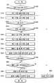
불량 노즐 검출 모드는 불량 노즐이 발생된 그룹을 검출하기 위한 제1시험 인쇄 패턴을 인쇄하는 단계(S10 단계)와, 검출수단(132)에 의해 상기 제1시험 인쇄 패턴으로부터 불량 노즐이 발생된 그룹을 검출하는 단계(S15, S20, S25, S30 단계)와, 상기 불량 노즐이 발생된 그룹에서 상기 불량 노즐이 몇 번째 위치되었는지를 검출하기 위한 제2시험 인쇄 패턴을 인쇄하는 단계(S35 단계), 및 검출수단(132)에 의해 제2시험 인쇄 패턴으로부터 불량 노즐이 발생된 위치를 검출하는 단계(S40, S45, S50 단계)를 포함한다. 이하, 각각의 단계에 대해 첨부된 도면을 참조하여 상세히 설명한다.The bad nozzle detection mode includes printing a first test print pattern for detecting a group in which a bad nozzle is generated (step S10), and a group in which a bad nozzle is generated from the first test print pattern by the detection means 132. Detecting (S15, S20, S25, S30), printing a second test print pattern for detecting the position of the defective nozzle in the group in which the defective nozzle is generated (step S35), And detecting the position where the defective nozzle is generated from the second test print pattern by the detection means 132 (steps S40, S45, S50). Hereinafter, each step will be described in detail with reference to the accompanying drawings.
도 10 및 도 8을 참조하면, 불량 노즐이 속한 그룹을 검출하기 위해 제어부(130)는 구동수단(160)의 동작을 제어하여 제1시험 인쇄 패턴을 인쇄한다(S10 단계). 본 발명의 노즐부(112)는 인쇄매체(P)의 폭에 해당되는 길이를 가지므로, 불량 노즐이 발생된 위치를 검출하기가 쉽지 않다. 따라서, 제어부(130)는 불량 노즐이 발생된 위치를 정확하게 검출하기 위해 각 노즐부(112)를 소정 개수의 그룹(G1, G2, G3...)으로 분할한다. 이와 같이 분할된 노즐부(112)에 의해 인쇄된 인쇄 패턴이 도 10에 도시되어 있다. 여기서, 검출수단(130)에 의해 분할된 각 그룹의 위치(G1, G2, G3...)가 용이하게 검출될 수 있도록, 제어부(130)는 제1시험 인쇄 패턴(T1C, T1M, T1Y, T1K)이 각 그룹의 위치를 나타내는 참조 표시(reference indication : RI)을 포함하도록 인쇄한다. 도시된 바와 같이, 참조 표시(RI)는 인쇄매체(P)의 폭방향(y 방향)으로 소정 간격 이격되며, 인쇄매체(P)의 이송방향(x 방향)으로 소정 길이를 갖는 선 모양인 것이 바람직하다.10 and 8, in order to detect a group to which a bad nozzle belongs, the
도 11을 참조하면, 검출수단(132)은 제1시험 인쇄 패턴(T1C, T1M, T1Y, T1K)을 스캐닝하여 불량 노즐이 속한 그룹을 검출한다(S15 단계). 먼저, 제1시험 인쇄 패턴(T1C, T1M, T1Y, T1K) 중 참조 표시(RI)가 검출수단(132)에 의해 스캐닝된다. 스캐닝된 참조 표시(RI)는 별도의 메모리(미도시)에 저장된다. 다음으로, 검출수단(132)은 제1시험 인쇄 패턴(T1C, T1M, T1Y, T1K)을 스캐닝하여 불량 노즐(defect nozzle)이 속하는 그룹이 어느 그룹에 속하는지를 검출한다. 이와 같이, 제1시험 인쇄 패턴(T1C, T1M, T1Y, T1K)으로부터 불량 노즐의 정확한 위치를 검출하지 않고 불량 노즐이 속한 그룹의 위치를 검출하는 이유는 화상형성장치에 설치된 스캐너와 같은 검출수단(132)으로는 정확한 노즐의 위치를 검출하는 것이 쉽지 않게 때문이다. 물론, 고가의 검출수단을 사용한다면 정확한 노즐의 위치를 검출할 수도 있겠지만, 고가의 검출수단을 사용할 경우 화상형성장치의 원가가 증가된다. 따라서, 상술한 바와 같이 참조 표시(RI)로부터 불량 노즐이 속한 그룹을 먼저 검출하는 것이 바람직하다.Referring to FIG. 11, the detecting
도 12는 제1시험 인쇄 패턴으로부터 불량 노즐이 속한 그룹을 검출하는 방법을 설명하기 위한 도면이다. 도 12는 검출수단으로 CCD 독취부를 이용하여 도 11에 도시된 제1시험 인쇄 패턴을 측정한 전압 신호(signal)를 보여주는 그래프이다.12 is a view for explaining a method of detecting a group to which a defective nozzle belongs from the first test print pattern. FIG. 12 is a graph showing a voltage signal obtained by measuring the first test print pattern shown in FIG. 11 using a CCD reading unit as a detection unit.
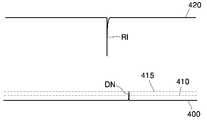
도 12 및 도 11을 참조하면, 검출수단(132)이 인쇄매체(P) 영역을 스캐닝시 출력 전압은 도시된 바와 같이 수평선을 갖는 참조번호 420의 파형을 갖는다. 그러나, 검출수단(132)이 블랙으로 인쇄된 참조 표시(RI) 부분을 스캐닝시 전압은 도시된 바와 같이 반사되는 광량의 차이로 인해 떨어진다. 이와 같은 원리로 각 노즐 그룹이 메모리(미도시)에 저장된다. 다음으로, 검출수단(132)이 인쇄영역을 스캐닝하면 전압은 참조번호 400의 파형을 갖는다. 불량 노즐이 발생되면, 불량 노즐에 의해 인쇄되는 영역과 정상 노즐에 의해 인쇄되는 영역 사이에는 농도 차이가 발생된다. 따라서, 검출수단(132)이 불량 노즐에 의해 인쇄되는 영역을 스캐닝시 도 12에 도시된 바와 같은 불량 노즐 발생 신호(signal)(DN)를 발생시킨다. 도시된 바와 같이, 불량 노즐 발생 신호(DN)는 문턱 전압(threshold level)(410)보다 높은 신호(signal)를 보이므로, 이와 같은 원리에 의해 불량 노즐이 발생된 그룹을 검출하게 된다. 여기서, 문턱 전압(threshold level)(410)은 불량 노즐을 검출하기 위해 기준이 되는 전압을 의미한다. 따라서, 검출수단(132)은 문턱 전압(410)을 기준으로 불량 노즐을 검출하게 된다.12 and 11, when the
그러나, 불량 노즐이 발생되지 않았음에도 노이즈(noise) 등에 의해 문턱 전압(410) 이상의 전압이 발생될 수 있다. 노이즈에 의한 검출 오차를 최소화하기 위해 상기 제1시험 인쇄 패턴(T1K)을 n회 반복하여 검출하고(S20 단계), 검출된 값(DN)이 문턱 전압(410) 이상인 횟수에 따라 불량 노즐인지 여부를 결정하는 것이 바람직하다(S25 단계). 일 실시예로서, n회 반복하여 검출시, 불량 노즐로 검출된 값(DN)이 반복 횟수의 70% 이상인 경우 불량 노즐로 판단하고, 이보다 작은 경우 노이즈(noise) 성분에 의한 것으로 판단하는 것이 바람직하다.However, even though a bad nozzle is not generated, a voltage higher than the
또한, 문턱 전압(410)이 불량 노즐 발생시의 전압(415)보다 높을 경우 불량 노즐이 발생되더라도 검출되지 않을 수 있다. 따라서, 인쇄하고자 하는 잉크의 색상(color)에 따라 문턱 전압(410)을 조절하여 불량 노즐 검출 성능을 향상시키는 것이 바람직하다. 일 실시예로서, 각각의 색상에 따라 인쇄영역을 스캐닝시 출력되는 전압(400)이 각각 다르게 나타난다. 여기서, 문턱 전압(410)을 각 색상에 따라 출력되는 출력 전압(400)에 근접되게 조정하면 불량 노즐 검출 성능을 향상시킬 수 있다.In addition, when the
또한, 불량 노즐 검출력을 높이기 위해 검출수단(132)은 제1시험 인쇄 패턴(T1K)에 따라 각 인쇄 패턴에 대응되는 보색광을 주사하는 것이 바람직하다. 예를 들어, 블랙 인쇄 패턴(T1K)의 경우 백색광이나 레드(Red), 그린(Green), 블루(Blue) 중 어느 하나의 광원을 주사하여 불량 노즐을 검출한다. 또한, 시안 인쇄 패턴(T1C)의 경우 레드(Red) 광원을, 마젠타 인쇄 패턴(T1M)의 경우 그린(Green) 광원을, 옐로우 인쇄 패턴(T1Y)의 경우 블루(Blue) 광원을 주사하여 불량 노즐을 검출하면 검출력을 향상시킬 수 있다.In addition, in order to increase the defective nozzle detection force, the detection means 132 preferably scans complementary light corresponding to each print pattern according to the first test print pattern T1K. For example, in the case of the black print pattern T1K, a bad nozzle is detected by scanning white light or one of red, green, and blue light sources. Also, a bad nozzle is scanned by scanning a red light source for a cyan print pattern T1C, a green light source for a magenta print pattern T1M, and a blue light source for a yellow print pattern T1Y. Detection can improve the detection power.
상술한 바와 같은 방법으로 1차적으로 불량 노즐이 발생된 그룹이 결정된다(S30 단계). 불량 노즐이 발생된 그룹이 결정되면, 상기 그룹으로부터 불량 노즐이 발생된 위치를 검출하여야 한다.In the manner as described above, the group in which the bad nozzle is generated is determined first (step S30). Once the group in which the bad nozzles are generated is determined, the position where the bad nozzles are generated from the group should be detected.
도 13은 본 발명에 따른 제2시험 인쇄 패턴을 보여주는 도면이고, 도 14는 제2시험 인쇄 패턴으로부터 불량 노즐 위치를 검출하는 방법을 설명하기 위한 도면이다.FIG. 13 is a view showing a second test print pattern according to the present invention, and FIG. 14 is a view for explaining a method of detecting a defective nozzle position from the second test print pattern.
도 13 및 도 8을 참조하면, 불량 노즐이 발생된 그룹에서 불량 노즐이 몇 번째 위치되었는지를 검출하기 위해, 제어부(130)는 구동수단(160)의 동작을 제어하여 제2시험 인쇄 패턴(T2C, T2M, T2Y, T2K)을 인쇄한다(S35 단계). 이때, 모든 노즐부(112)에 대해 인쇄할 필요없이 도 13에 도시된 바와 같이 불량 노즐이 속한 것으로 검출된 그룹에 대해서만 인쇄하는 것이 바람직하다. 제어부(130)는 검출수단 (132)이 상기 그룹에서 불량 노즐이 몇 번째 위치되었는지를 검출할 수 있도록, 도 13에 도시된 바와 같이 불량 노즐이 속한 그룹의 첫 번째 노즐부터 소정 시간 간격으로 각 노즐들을 순차적으로 구동시켜 제2시험 인쇄 패턴(T2C, T2M, T2Y, T2K)을 인쇄하는 것이 바람직하다(S40 단계).Referring to FIGS. 13 and 8, in order to detect how many defective nozzles are located in the group in which the defective nozzles are generated, the
이하, 설명의 빠른 이해를 위해 도 13에 도시된 제2시험 인쇄 패턴(T2C, T2M, T2Y, T2K) 중 블랙 인쇄 패턴(T2K)을 예로 들어 설명한다. 도 13에 도시된 실시예에서는 10개의 노즐 단위로 노즐부(112)의 노즐들을 그룹핑하였다.Hereinafter, the black test pattern T2K of the second test print patterns T2C, T2M, T2Y, and T2K shown in FIG. 13 will be described as an example for quick understanding. In the embodiment shown in FIG. 13, the nozzles of the
도 14, 도 13, 및 도 8을 참조하면, N1 노즐은 정상 노즐이므로 도시된 바와 같이 정상적으로 인쇄된다. 인쇄매체(P)가 검출수단(132)의 검출 영역을 통과시 N1 노즐에 의해 인쇄된 부분에만 블랙 색상이 인쇄된다. 따라서, 검출수단(132)은 도시된 바와 같이 N1 노즐에 대응하는 n1 신호(signal)를 발생시킨다. 다음으로, 검출수단(132)은 N2 노즐에 대응하는 n2 신호를 발생시킨다. 즉, 정상 노즐의 경우 도시된 바와 같은 신호(n1, n2, n6, n10)를 발생시킨다.14, 13, and 8, since the N1 nozzle is a normal nozzle, it is normally printed as shown. When the print medium P passes through the detection area of the detection means 132, black color is printed only on the portion printed by the N1 nozzle. Accordingly, the detection means 132 generates an n1 signal corresponding to the N1 nozzle as shown. Next, the detection means 132 generates an n2 signal corresponding to the N2 nozzle. That is, in the case of the normal nozzle, the signals n1, n2, n6, n10 as shown are generated.
한편, 불량 노즐 발생시 도 13에 도시된 바와 같이 인쇄가 이루어지지 않거나 인쇄 농도가 낮게 인쇄된다(DN). 따라서, 검출수단(132)은 불량 노즐인 N5 노즐에 의해 인쇄되는 영역에서는 신호를 발생시키지 않거나 약한 신호를 발생시키게 된다. 즉, 정상 노즐에 의해 인쇄되는 영역과 불량 노즐에 의해 인쇄되는 영역 사이에는 상기와 같은 신호(signal) 차이가 발생되므로, 검출수단(132)은 이를 이용하여 불량 노즐의 위치를 검출하게 된다. 제1시험 인쇄 패턴(T1C, T1M, T1Y, T1K)의 검출시와 같이, 불량 노즐 발생 위치에 대한 검출력을 높이기 위해 검출수단 (132)은 제2시험 인쇄 패턴(T2C, T2M, T2Y, T2K)에 따라 각 인쇄 패턴에 보색광을 주사하는 것이 바람직하다.On the other hand, when a bad nozzle occurs, as shown in FIG. 13, printing is not performed or print density is low (DN). Therefore, the detection means 132 does not generate a signal or generates a weak signal in the area printed by the N5 nozzle which is a defective nozzle. That is, since the signal difference is generated between the area printed by the normal nozzle and the area printed by the bad nozzle, the detection means 132 detects the location of the bad nozzle using the same. As in the case of detecting the first test print patterns T1C, T1M, T1Y, and T1K, the detection means 132 performs a second test print pattern (T2C, T2M, T2Y, T2K) in order to increase the detection force on the defective nozzle occurrence position. In accordance with this, it is preferable to scan complementary light on each printing pattern.
상술한 바와 같이 본 발명은 제1시험 인쇄 패턴으로부터 불량 노즐이 속한 그룹을 검출하고, 제2시험 인쇄 패턴으로부터 불량 노즐이 발생된 정확한 위치를 검출하게 된다. 검출수단(132)에 의해 검출된 불량 노즐의 위치는 별도의 메모리(미도시)에 저장된다. 불량 노즐이 발생되면 인쇄 화질이 저하된다. 따라서, 불량 노즐을 회복시키거나 이를 보상하며 인쇄 작업을 수행하는 것이 바람직하다.As described above, the present invention detects the group to which the bad nozzle belongs from the first test print pattern, and detects the exact position where the bad nozzle is generated from the second test print pattern. The position of the bad nozzle detected by the detecting means 132 is stored in a separate memory (not shown). If a bad nozzle occurs, print quality deteriorates. Therefore, it is desirable to perform a print job while recovering or compensating for a defective nozzle.
도 8 및 도 9를 참조하면, 불량 노즐 발생시 제어부(130)는 메인티넌스부(165)의 동작을 제어하여, 불량 노즐을 인쇄 대기 상태로 회복시키기 위한 회복 동작(maintenance)을 실시하는 것이 바람직하다(S50 단계). 또한, 회복 동작은 불량 노즐이나 불량 노즐이 속한 그룹에 대해 소정 횟수 반복하여 실시하는 것이 보다 바람직하다(S55 단계). 이와 같이 회복 동작을 실시한 후 검출수단(132)을 이용하여 불량 노즐이 회복되었는지를 다시 검출한다(S60 단계). 제어부(130)는 불량 노즐이 회복되었다면 일반 모드로 인쇄(S80 단계)하도록 하고, 그렇지 않은 경우 불량 노즐의 위치를 메모리(미도시)에 저장시킨 후(S65 단계) 저장된 불량 노즐 정보에 따라 불량 노즐을 보상하며 인쇄 작업을 수행하도록 한다. 불량 노즐 보상 방법으로는 프린트 헤드를 진동시키며 인쇄하거나, 에러 분산(error diffusion) 방법을 이용하여 불량 노즐을 보상하는 방법 등이 있다.8 and 9, when a bad nozzle is generated, the
상술한 바와 같은 구성 및 방법에 의하면, 본 발명은 2단계의 시험 인쇄 패턴으로부터 불량 노즐의 위치를 용이하게 검출할 수 있다.According to the above-described configuration and method, the present invention can easily detect the position of the defective nozzle from the two-step test print pattern.
이상에서 설명한 바와 같이, 본 발명에 따른 잉크젯 화상형성장치 및 잉크젯 화상형성장치의 불량 노즐 검출 방법은 고가의 검출수단을 사용하지 않고도 라인 프린팅 방식 잉크젯 화상형성장치의 불량 노즐의 발생 위치를 정확하게 검출할 수 있다. 셔틀 방식 잉크젯 화상형성장치와 달리 라인 프린팅 방식 잉크젯 화상형성장치의 노즐부는 인쇄매체의 폭에 해당되는 길이로 구성되므로 불량 노즐을 검출하기가 쉽지 않다. 본 발명은 제1시험 인쇄 패턴으로부터 불량 노즐이 속한 그룹을 검출하고, 제2시험 인쇄 패턴으로부터 불량 노즐의 위치를 검출한다. 이와 같이 2단계의 시험 인쇄 패턴을 인쇄하여 불량 노즐을 검출함으로써 저가의 검출수단을 사용하더라도 불량 노즐을 용이하게 검출할 수 있다. 또한, 본 발명은 불량 노즐 발생시 사용자의 선택이나 화상형성장치의 자가 진단을 통해 회복 동작을 실시함으로써, 찌꺼기 등에 의한 노즐 막힘 등 불량 노즐 발생시 이를 회복시켜 인쇄할 수 있으므로 프린트 헤드의 수명을 향상시킬 수 있다. 또한, 본 발명은 회복 동작에 의해서도 불량 노즐이 회복되지 않을 경우 불량 노즐에 대한 정보를 별도의 메모리에 저장한 후, 이후의 인쇄 작업시 상기 불량 노즐에 대한 정보를 제공하여 불량 노즐을 보상하며 인쇄하도록 할 수 있다.As described above, the defective nozzle detection method of the inkjet image forming apparatus and the inkjet image forming apparatus according to the present invention can accurately detect the occurrence position of the defective nozzle of the line printing type inkjet image forming apparatus without using expensive detecting means. Can be. Unlike the shuttle inkjet image forming apparatus, the nozzle portion of the line printing inkjet image forming apparatus is configured to have a length corresponding to the width of the printing medium, so that it is difficult to detect a defective nozzle. The present invention detects the group to which the bad nozzle belongs from the first test print pattern, and detects the position of the bad nozzle from the second test print pattern. In this way, by printing the two-step test print pattern to detect the defective nozzles, the defective nozzles can be easily detected even using a low-cost detection means. In addition, the present invention can perform a recovery operation through the user's selection or self-diagnosis of the image forming apparatus when a bad nozzle occurs, it is possible to recover and print when a bad nozzle, such as nozzle clogging due to debris can improve the life of the print head have. In addition, the present invention stores the information about the bad nozzles in a separate memory when the bad nozzles are not recovered even by the recovery operation, and provides information on the bad nozzles in a subsequent print job to compensate for the bad nozzles and print. You can do that.
본 발명은 도면에 도시된 실시예를 참고로 하여 설명되었으나, 이는 예시적인 것에 불과하며, 당해 기술이 속하는 분야에서 통상의 지식을 가진 자라면 이로부터 다양한 변형 및 균등한 타 실시예가 가능하다는 점을 이해할 것이다. 따라서, 본 발명의 진정한 기술적 보호범위는 아래의 특허청구범위에 의해서 정하여져야 할 것이다.Although the present invention has been described with reference to the embodiments shown in the drawings, this is merely exemplary, and those skilled in the art to which the art belongs can make various modifications and other equivalent embodiments therefrom. Will understand. Therefore, the true technical protection scope of the present invention will be defined by the claims below.
Claims (20)
Translated fromKoreanPriority Applications (3)
| Application Number | Priority Date | Filing Date | Title |
|---|---|---|---|
| KR1020050071693AKR100717018B1 (en) | 2005-08-05 | 2005-08-05 | Defective nozzle detection method of inkjet image forming apparatus and inkjet image forming apparatus |
| US11/476,751US20070030300A1 (en) | 2005-08-05 | 2006-06-29 | Inkjet image forming apparatus, and method of detecting malfunctioning nozzle thereof |
| CNA2006101009600ACN1907708A (en) | 2005-08-05 | 2006-08-04 | Inkjet image forming apparatus, and method of detecting malfunctioning nozzle thereof |
Applications Claiming Priority (1)
| Application Number | Priority Date | Filing Date | Title |
|---|---|---|---|
| KR1020050071693AKR100717018B1 (en) | 2005-08-05 | 2005-08-05 | Defective nozzle detection method of inkjet image forming apparatus and inkjet image forming apparatus |
Publications (2)
| Publication Number | Publication Date |
|---|---|
| KR20070016746A KR20070016746A (en) | 2007-02-08 |
| KR100717018B1true KR100717018B1 (en) | 2007-05-10 |
Family
ID=37699012
Family Applications (1)
| Application Number | Title | Priority Date | Filing Date |
|---|---|---|---|
| KR1020050071693AExpired - Fee RelatedKR100717018B1 (en) | 2005-08-05 | 2005-08-05 | Defective nozzle detection method of inkjet image forming apparatus and inkjet image forming apparatus |
Country Status (3)
| Country | Link |
|---|---|
| US (1) | US20070030300A1 (en) |
| KR (1) | KR100717018B1 (en) |
| CN (1) | CN1907708A (en) |
Cited By (1)
| Publication number | Priority date | Publication date | Assignee | Title |
|---|---|---|---|---|
| US10509340B2 (en) | 2016-10-17 | 2019-12-17 | Hp Printing Korea Co., Ltd. | Image forming apparatus and method for color registration correction |
Families Citing this family (38)
| Publication number | Priority date | Publication date | Assignee | Title |
|---|---|---|---|---|
| JP2008307827A (en)* | 2007-06-15 | 2008-12-25 | Fujifilm Corp | Inkjet image forming method and image forming apparatus |
| JP4862807B2 (en)* | 2007-11-30 | 2012-01-25 | ブラザー工業株式会社 | Image recording device |
| US8449068B2 (en)* | 2009-02-19 | 2013-05-28 | Hewlett-Packard Development Company, L.P. | Light-scattering drop detector |
| US8177318B2 (en)* | 2008-03-25 | 2012-05-15 | Hewlett-Packard Development Company, L.P. | Orifice health detection device |
| US8529011B2 (en)* | 2008-03-25 | 2013-09-10 | Hewlett-Packard Development Company, L.P. | Drop detection mechanism and a method of use thereof |
| US8100499B2 (en)* | 2009-03-30 | 2012-01-24 | Xerox Corporation | Method and system for detecting print head roll |
| US8511786B2 (en)* | 2009-10-19 | 2013-08-20 | Hewlett-Packard Development Company, L.P. | Light scattering drop detect device with volume determination and method |
| JP5328630B2 (en)* | 2009-12-18 | 2013-10-30 | キヤノン株式会社 | Inkjet recording apparatus and method for determining number of preliminary ejections |
| JP5473704B2 (en)* | 2010-03-24 | 2014-04-16 | 富士フイルム株式会社 | Test pattern printing method and inkjet recording apparatus |
| CN101839865A (en)* | 2010-04-13 | 2010-09-22 | 富美科技有限公司 | Automatic distinguishing method of printing effect |
| US8355127B2 (en) | 2010-07-15 | 2013-01-15 | Hewlett-Packard Development Company, L.P. | GRIN lens array light projector and method |
| JP5631663B2 (en)* | 2010-08-27 | 2014-11-26 | 富士フイルム株式会社 | Image recording device |
| JP5729972B2 (en)* | 2010-11-10 | 2015-06-03 | キヤノン株式会社 | Inkjet recording apparatus and inkjet recording method |
| US9493019B2 (en) | 2011-06-10 | 2016-11-15 | Hewlett-Packard Development Company, L.P. | Printing system with oscillating pagewide printhead |
| EP2836366B1 (en)* | 2012-04-09 | 2019-10-23 | Hewlett-Packard Development Company, L.P. | Nozzle ejection trajectory detection |
| TWI607889B (en)* | 2012-09-21 | 2017-12-11 | 滿捷特科技公司 | Method, printing medium and device for discriminating defective nozzles in an inkjet head |
| CN104442038A (en)* | 2013-09-13 | 2015-03-25 | 研能科技股份有限公司 | Printing compensation method suitable for printing module |
| JP2015182337A (en)* | 2014-03-25 | 2015-10-22 | セイコーエプソン株式会社 | Printing device, control method, and printing system |
| JP6565331B2 (en)* | 2014-06-30 | 2019-08-28 | 株式会社リコー | Nozzle inspection apparatus and image forming apparatus |
| JP6300699B2 (en)* | 2014-10-08 | 2018-03-28 | 富士フイルム株式会社 | Test image, test image forming system, test image forming method, test image forming program, storage medium, storage medium, abnormal recording element detection system, abnormal recording element detection method, abnormal recording element detection program, and storage medium |
| US9216603B1 (en)* | 2015-01-23 | 2015-12-22 | Xerox Corporation | System and method for generation of test patterns for measurement of printhead to substrate separation in a printer |
| JP6374328B2 (en)* | 2015-02-02 | 2018-08-15 | 株式会社沖データ | Recording device |
| JP6408946B2 (en)* | 2015-03-25 | 2018-10-17 | 株式会社沖データ | Recording device |
| CN105651501B (en)* | 2015-12-25 | 2018-04-20 | 广州兴森快捷电路科技有限公司 | The detection method of condition of nozzles under a kind of horizontal line |
| JP7060521B2 (en)* | 2016-07-29 | 2022-04-26 | ヒューレット-パッカード デベロップメント カンパニー エル.ピー. | Printing devices, computer-readable media and printing methods |
| DE102016117211A1 (en)* | 2016-09-13 | 2018-03-15 | Schmid Rhyner Ag | Method and device for ink-jet application on flat substrates |
| CN108995377B (en)* | 2017-06-07 | 2020-08-07 | 北大方正集团有限公司 | Inkjet digital printing system, activation method, activation device and readable medium |
| DE102017211988A1 (en)* | 2017-07-13 | 2019-01-17 | Heidelberger Druckmaschinen Ag | Detection of failed pressure nozzles at the pressure edge |
| CN107745586A (en)* | 2017-10-18 | 2018-03-02 | 佛山市东鹏陶瓷有限公司 | A kind of detection method and its ceramic tile production process to inkjet printing defect |
| DE102018217476A1 (en)* | 2017-11-22 | 2019-05-23 | Heidelberger Druckmaschinen Ag | Variable pressure nozzle test pattern |
| WO2019172869A1 (en)* | 2018-03-05 | 2019-09-12 | Hewlett-Packard Development Company, L.P. | Zonal actuator fault detection with scan mode signal propagation |
| CN109866505A (en)* | 2019-01-29 | 2019-06-11 | 北大方正集团有限公司 | Nozzle maintenance method, device, equipment and storage medium |
| JP7408980B2 (en)* | 2019-09-27 | 2024-01-09 | コニカミノルタ株式会社 | Image forming device, image forming system and program |
| DE102019216153A1 (en)* | 2019-10-21 | 2021-04-22 | Heidelberger Druckmaschinen Ag | Closed-loop GVA |
| CN111300987B (en)* | 2020-02-27 | 2021-02-02 | 深圳怡化电脑股份有限公司 | Ink jet interval time determining method, device, computer equipment and storage medium |
| EP3871892B1 (en)* | 2020-02-28 | 2022-02-09 | Heidelberger Druckmaschinen AG | Detektion method to minimize maculature |
| CN113002179B (en)* | 2021-02-23 | 2022-08-12 | 上海汉图科技有限公司 | An inkjet printer maintenance method and inkjet printer |
| JP2023053672A (en) | 2021-10-01 | 2023-04-13 | セイコーエプソン株式会社 | Recording device, recording and reading system, and recording method |
Citations (3)
| Publication number | Priority date | Publication date | Assignee | Title |
|---|---|---|---|---|
| JP2002059565A (en) | 2000-06-05 | 2002-02-26 | Fuji Photo Film Co Ltd | Method and apparatus for recording image |
| KR20050001217A (en)* | 2003-06-27 | 2005-01-06 | 삼성전자주식회사 | Detecting method of missing nozzles in a inkjet printer |
| JP2005022218A (en) | 2003-07-01 | 2005-01-27 | Seiko Epson Corp | Discharge inspection apparatus, discharge inspection method, and printing system |
Family Cites Families (5)
| Publication number | Priority date | Publication date | Assignee | Title |
|---|---|---|---|---|
| US5587730A (en)* | 1994-09-30 | 1996-12-24 | Xerox Corporation | Redundant full width array thermal ink jet printing for improved reliability |
| US5880852A (en)* | 1995-05-23 | 1999-03-09 | Canon Kabushiki Kaisha | Reading unit and recording apparatus on which the reading unit is mountable |
| US6672706B2 (en)* | 1997-07-15 | 2004-01-06 | Silverbrook Research Pty Ltd | Wide format pagewidth inkjet printer |
| US6715854B2 (en)* | 2001-10-31 | 2004-04-06 | Hewlett-Packard Development Company, L.P. | Installing printheads in a hardcopy apparatus |
| US20050018006A1 (en)* | 2003-06-27 | 2005-01-27 | Samsung Electronics Co., Ltd. | Method of determining missing nozzles in an inkjet printer |
- 2005
- 2005-08-05KRKR1020050071693Apatent/KR100717018B1/ennot_activeExpired - Fee Related
- 2006
- 2006-06-29USUS11/476,751patent/US20070030300A1/ennot_activeAbandoned
- 2006-08-04CNCNA2006101009600Apatent/CN1907708A/enactivePending
Patent Citations (3)
| Publication number | Priority date | Publication date | Assignee | Title |
|---|---|---|---|---|
| JP2002059565A (en) | 2000-06-05 | 2002-02-26 | Fuji Photo Film Co Ltd | Method and apparatus for recording image |
| KR20050001217A (en)* | 2003-06-27 | 2005-01-06 | 삼성전자주식회사 | Detecting method of missing nozzles in a inkjet printer |
| JP2005022218A (en) | 2003-07-01 | 2005-01-27 | Seiko Epson Corp | Discharge inspection apparatus, discharge inspection method, and printing system |
Cited By (2)
| Publication number | Priority date | Publication date | Assignee | Title |
|---|---|---|---|---|
| US10509340B2 (en) | 2016-10-17 | 2019-12-17 | Hp Printing Korea Co., Ltd. | Image forming apparatus and method for color registration correction |
| US10908524B2 (en) | 2016-10-17 | 2021-02-02 | Hewlett-Packard Development Company, L.P. | Image forming apparatus and method for color registration correction |
Also Published As
| Publication number | Publication date |
|---|---|
| CN1907708A (en) | 2007-02-07 |
| KR20070016746A (en) | 2007-02-08 |
| US20070030300A1 (en) | 2007-02-08 |
Similar Documents
| Publication | Publication Date | Title |
|---|---|---|
| KR100717018B1 (en) | Defective nozzle detection method of inkjet image forming apparatus and inkjet image forming apparatus | |
| KR100750161B1 (en) | Defective nozzle compensation method and apparatus for inkjet image forming apparatus | |
| KR100788664B1 (en) | Printhead and scanning-type inkjet image forming apparatus having the same, and high resolution implementation method | |
| KR100833232B1 (en) | Defective nozzle compensation method of inkjet image forming apparatus and inkjet image forming apparatus | |
| CN1978197B (en) | Method and device for compensating faulty nozzles and inkjet image forming device using the same | |
| US7533953B2 (en) | Method and apparatus for compensating for defective nozzle in inkjet image forming apparatus | |
| CN100482469C (en) | Inkjet image forming apparatus and method of performing high resolution printing using a multi-pass method | |
| KR20070095465A (en) | High quality printing method of inkjet image forming apparatus and inkjet image forming apparatus | |
| KR20070054322A (en) | Defective nozzle compensation method, apparatus and recording medium of inkjet image forming apparatus | |
| KR100823257B1 (en) | Printing method of inkjet image forming apparatus and inkjet image forming apparatus | |
| CN101372180A (en) | Inkjet imaging device and printing method thereof | |
| CN1939729B (en) | Ink jet image forming apparatus, and method for compensating defective nozzle thereof | |
| US20050285896A1 (en) | Ejection head, image forming apparatus and image forming method | |
| KR100644709B1 (en) | Defective nozzle compensation method of print head, ink jet image forming apparatus and ink jet image forming apparatus | |
| US7703871B2 (en) | Liquid ejecting device and method of controlling liquid ejecting device | |
| KR100694120B1 (en) | Line printing method inkjet image forming apparatus and printing quality improvement method | |
| KR20070022847A (en) | High quality printing method of inkjet image forming apparatus and inkjet image forming apparatus | |
| KR100833231B1 (en) | An image potential printing method of an inkjet image forming apparatus and an inkjet image forming apparatus | |
| KR100694136B1 (en) | Inkjet Image Forming Device and Defective Nozzle Compensation Method | |
| JP4529376B2 (en) | Liquid ejection device, correction pattern, correction pattern forming method, and liquid ejection system | |
| KR100694122B1 (en) | Compensation method of inkjet image forming apparatus | |
| KR20070041706A (en) | Printing method of inkjet image forming apparatus and inkjet image forming apparatus |
Legal Events
| Date | Code | Title | Description |
|---|---|---|---|
| A201 | Request for examination | ||
| PA0109 | Patent application | St.27 status event code:A-0-1-A10-A12-nap-PA0109 | |
| PA0201 | Request for examination | St.27 status event code:A-1-2-D10-D11-exm-PA0201 | |
| D13-X000 | Search requested | St.27 status event code:A-1-2-D10-D13-srh-X000 | |
| D14-X000 | Search report completed | St.27 status event code:A-1-2-D10-D14-srh-X000 | |
| E902 | Notification of reason for refusal | ||
| PE0902 | Notice of grounds for rejection | St.27 status event code:A-1-2-D10-D21-exm-PE0902 | |
| E13-X000 | Pre-grant limitation requested | St.27 status event code:A-2-3-E10-E13-lim-X000 | |
| P11-X000 | Amendment of application requested | St.27 status event code:A-2-2-P10-P11-nap-X000 | |
| P13-X000 | Application amended | St.27 status event code:A-2-2-P10-P13-nap-X000 | |
| PG1501 | Laying open of application | St.27 status event code:A-1-1-Q10-Q12-nap-PG1501 | |
| E701 | Decision to grant or registration of patent right | ||
| PE0701 | Decision of registration | St.27 status event code:A-1-2-D10-D22-exm-PE0701 | |
| GRNT | Written decision to grant | ||
| PR0701 | Registration of establishment | St.27 status event code:A-2-4-F10-F11-exm-PR0701 | |
| PR1002 | Payment of registration fee | St.27 status event code:A-2-2-U10-U11-oth-PR1002 Fee payment year number:1 | |
| PG1601 | Publication of registration | St.27 status event code:A-4-4-Q10-Q13-nap-PG1601 | |
| LAPS | Lapse due to unpaid annual fee | ||
| PC1903 | Unpaid annual fee | St.27 status event code:A-4-4-U10-U13-oth-PC1903 Not in force date:20100505 Payment event data comment text:Termination Category : DEFAULT_OF_REGISTRATION_FEE | |
| PC1903 | Unpaid annual fee | St.27 status event code:N-4-6-H10-H13-oth-PC1903 Ip right cessation event data comment text:Termination Category : DEFAULT_OF_REGISTRATION_FEE Not in force date:20100505 | |
| R18-X000 | Changes to party contact information recorded | St.27 status event code:A-5-5-R10-R18-oth-X000 | |
| P22-X000 | Classification modified | St.27 status event code:A-4-4-P10-P22-nap-X000 |