KR100715069B1 - Push on switch, electronic apparatus mounted with same, and method for mounting same - Google Patents
Push on switch, electronic apparatus mounted with same, and method for mounting sameDownload PDFInfo
- Publication number
- KR100715069B1 KR100715069B1KR1020010003203AKR20010003203AKR100715069B1KR 100715069 B1KR100715069 B1KR 100715069B1KR 1020010003203 AKR1020010003203 AKR 1020010003203AKR 20010003203 AKR20010003203 AKR 20010003203AKR 100715069 B1KR100715069 B1KR 100715069B1
- Authority
- KR
- South Korea
- Prior art keywords
- switch
- push
- wiring board
- printed wiring
- contact
- Prior art date
- Legal status (The legal status is an assumption and is not a legal conclusion. Google has not performed a legal analysis and makes no representation as to the accuracy of the status listed.)
- Expired - Fee Related
Links
Images


Classifications
- H—ELECTRICITY
- H01—ELECTRIC ELEMENTS
- H01H—ELECTRIC SWITCHES; RELAYS; SELECTORS; EMERGENCY PROTECTIVE DEVICES
- H01H13/00—Switches having rectilinearly-movable operating part or parts adapted for pushing or pulling in one direction only, e.g. push-button switch
- H01H13/70—Switches having rectilinearly-movable operating part or parts adapted for pushing or pulling in one direction only, e.g. push-button switch having a plurality of operating members associated with different sets of contacts, e.g. keyboard
- H01H13/78—Switches having rectilinearly-movable operating part or parts adapted for pushing or pulling in one direction only, e.g. push-button switch having a plurality of operating members associated with different sets of contacts, e.g. keyboard characterised by the contacts or the contact sites
- H01H13/807—Switches having rectilinearly-movable operating part or parts adapted for pushing or pulling in one direction only, e.g. push-button switch having a plurality of operating members associated with different sets of contacts, e.g. keyboard characterised by the contacts or the contact sites characterised by the spatial arrangement of the contact sites, e.g. superimposed sites
- H—ELECTRICITY
- H01—ELECTRIC ELEMENTS
- H01H—ELECTRIC SWITCHES; RELAYS; SELECTORS; EMERGENCY PROTECTIVE DEVICES
- H01H13/00—Switches having rectilinearly-movable operating part or parts adapted for pushing or pulling in one direction only, e.g. push-button switch
- H01H13/02—Details
- H—ELECTRICITY
- H01—ELECTRIC ELEMENTS
- H01H—ELECTRIC SWITCHES; RELAYS; SELECTORS; EMERGENCY PROTECTIVE DEVICES
- H01H1/00—Contacts
- H01H1/58—Electric connections to or between contacts; Terminals
- H01H1/5805—Connections to printed circuits
- H—ELECTRICITY
- H01—ELECTRIC ELEMENTS
- H01H—ELECTRIC SWITCHES; RELAYS; SELECTORS; EMERGENCY PROTECTIVE DEVICES
- H01H13/00—Switches having rectilinearly-movable operating part or parts adapted for pushing or pulling in one direction only, e.g. push-button switch
- H01H13/02—Details
- H01H13/26—Snap-action arrangements depending upon deformation of elastic members
- H01H13/48—Snap-action arrangements depending upon deformation of elastic members using buckling of disc springs
- H—ELECTRICITY
- H01—ELECTRIC ELEMENTS
- H01H—ELECTRIC SWITCHES; RELAYS; SELECTORS; EMERGENCY PROTECTIVE DEVICES
- H01H1/00—Contacts
- H01H1/58—Electric connections to or between contacts; Terminals
- H01H2001/5888—Terminals of surface mounted devices [SMD]
- H—ELECTRICITY
- H01—ELECTRIC ELEMENTS
- H01H—ELECTRIC SWITCHES; RELAYS; SELECTORS; EMERGENCY PROTECTIVE DEVICES
- H01H2205/00—Movable contacts
- H01H2205/016—Separate bridge contact
- H01H2205/024—Means to facilitate positioning
- H01H2205/026—Adhesive sheet
- H—ELECTRICITY
- H01—ELECTRIC ELEMENTS
- H01H—ELECTRIC SWITCHES; RELAYS; SELECTORS; EMERGENCY PROTECTIVE DEVICES
- H01H2221/00—Actuators
- H01H2221/008—Actuators other then push button
- H01H2221/014—Slide selector
- H—ELECTRICITY
- H01—ELECTRIC ELEMENTS
- H01H—ELECTRIC SWITCHES; RELAYS; SELECTORS; EMERGENCY PROTECTIVE DEVICES
- H01H2221/00—Actuators
- H01H2221/062—Damping vibrations
- H—ELECTRICITY
- H01—ELECTRIC ELEMENTS
- H01H—ELECTRIC SWITCHES; RELAYS; SELECTORS; EMERGENCY PROTECTIVE DEVICES
- H01H2225/00—Switch site location
- H01H2225/028—Switch site location perpendicular to base of keyboard
- H—ELECTRICITY
- H01—ELECTRIC ELEMENTS
- H01H—ELECTRIC SWITCHES; RELAYS; SELECTORS; EMERGENCY PROTECTIVE DEVICES
- H01H2239/00—Miscellaneous
- H01H2239/008—Static electricity considerations
- H—ELECTRICITY
- H01—ELECTRIC ELEMENTS
- H01H—ELECTRIC SWITCHES; RELAYS; SELECTORS; EMERGENCY PROTECTIVE DEVICES
- H01H9/00—Details of switching devices, not covered by groups H01H1/00 - H01H7/00
- H01H9/12—Means for earthing parts of switch not normally conductively connected to the contacts
Landscapes
- Physics & Mathematics (AREA)
- Electromagnetism (AREA)
- Push-Button Switches (AREA)
Abstract
Translated fromKoreanDescription
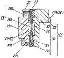
Translated fromKorean도 1은 본 발명의 제 1 실시예에 의한 푸시온 스위치의 단면도,1 is a cross-sectional view of a push-on switch according to a first embodiment of the present invention,
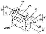
도 2는 본 발명의 제 1 실시예에 의한 푸시온 스위치의 완성 상태의 사시도,2 is a perspective view of a completed state of a push-on switch according to a first embodiment of the present invention;
도 3은 본 발명의 제 1 실시예에 의한 푸시온 스위치의 분해 사시도,3 is an exploded perspective view of a push-on switch according to a first embodiment of the present invention;
도 4는 본 발명의 제 1 실시예에 의한 푸시온 스위치의 가압 조작 상태를 도시하는 단면도,4 is a cross-sectional view showing a pressing operation state of a push-on switch according to the first embodiment of the present invention;
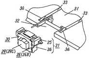
도 5a는 본 발명의 제 1 실시예에 의한 푸시온 스위치의 장착 방법을 설명하는 사시도,5A is a perspective view illustrating a mounting method of a push-on switch according to a first embodiment of the present invention;
도 5b는 본 발명의 제 1 실시예에 의한 푸시온 스위치의 다른 장착 방법을 설명하는 사시도,5B is a perspective view for explaining another mounting method of the push-on switch according to the first embodiment of the present invention;
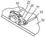
도 6은 본 발명의 제 1 실시예에 의한 푸시온 스위치가 프린트 배선판에 탑재된 상태를 도시하는 전자기기의 부분 사시도,6 is a partial perspective view of an electronic apparatus showing a state in which a push-on switch according to a first embodiment of the present invention is mounted on a printed wiring board;
도 7a는 본 발명의 제 1 실시예에 의한 푸시온 스위치가 프린트 배선판에 조금 어긋나게 탑재된 상태를 도시하는 단면도,FIG. 7A is a cross-sectional view showing a state in which a push-on switch according to a first embodiment of the present invention is mounted slightly off a printed wiring board; FIG.
도 7b는 본 발명의 제 1 실시예에 의한 푸시온 스위치의 납땜 고정 후의 상태를 도시하는 단면도,7B is a cross-sectional view showing a state after soldering fixing of a push-on switch according to the first embodiment of the present invention;
도 8은 본 발명의 제 2 실시예에 의한 푸시온 스위치의 단면도,8 is a cross-sectional view of a push-on switch according to a second embodiment of the present invention;
도 9는 본 발명의 제 2 실시예에 의한 푸시온 스위치의 가압 조작 상태를 도시하는 단면도,9 is a sectional view showing a pressurizing operation state of a push-on switch according to a second embodiment of the present invention;
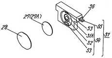
도 10은 본 발명의 제 3 실시예에 의한 푸시온 스위치의 사시도,10 is a perspective view of a push-on switch according to a third embodiment of the present invention;
도 11은 본 발명의 제 3 실시예에 의한 푸시온 스위치의 분해 사시도,11 is an exploded perspective view of a push-on switch according to a third embodiment of the present invention;
도 12는 본 발명의 제 4 실시예에 의한 푸시온 스위치를 장착하는 상태를 도시하는 전자기기의 부분 사시도,12 is a partial perspective view of an electronic apparatus showing a state in which a push-on switch according to a fourth embodiment of the present invention is mounted;
도 13은 본 발명의 제 5 실시예에 의한 푸시온 스위치를 프린트 배선판에 장착한 상태를 도시하는 전자기기의 부분 사시도,Fig. 13 is a partial perspective view of an electronic apparatus showing a state in which a push-on switch according to a fifth embodiment of the present invention is mounted on a printed wiring board;
도 14는 본 발명의 제 5 실시예에 의한 푸시온 스위치를 프린트 배선판에 장착한 다른 장착 상태를 도시하는 부분 사시도,14 is a partial perspective view showing another mounting state in which the push-on switch according to the fifth embodiment of the present invention is mounted on a printed wiring board;
도 15는 종래의 푸시온 스위치의 단면도,15 is a cross-sectional view of a conventional push-on switch,
도 16은 종래의 푸시온 스위치의 분해 사시도.
16 is an exploded perspective view of a conventional push-on switch.
도면의 주요 부분에 대한 부호의 설명Explanation of symbols for the main parts of the drawings
21 : 케이스21A : 케이스의 오목부21
22B : 벽부22 : 중앙 고정 접점22B: wall portion 22: center fixed contact
23 : 외측 고정 접점24 : 스위치 본체부23: outside fixed contact 24: switch body portion
25 : 수취부26 : 접속용 단자25: receiver 26: terminal for connection
26A : 평행부27 : 반구형상 가동 접점26A: Parallel part 27: Hemispherical movable contact
27A : 중앙 정점부28 : 절연 시트27A: center vertex 28: insulation sheet
29 : 조작체29A : 가압부29:
29B : 플랜지부29C : 조작부29B: Flange 29C: Operation
30 : 커버30A : 개구부
30:
본 발명은 각종 전자기기의 조작 부분 등에 사용되는 횡가압식 푸시온 스위치와 그것을 장착한 전자기기 및 그 장착 방법에 관한 것이다.BACKGROUND OF THE
최근, 전자기기의 구성상, 프린트 배선판면에 대하여 평행하게 가압 조작하는 횡가압식의 저렴한 푸시온 스위치에 대한 요망이 높아지고 있고, 또한 전자기기의 소형·박형화에 따라, 그것에 대응할 수 있는 푸시온 스위치에 대한 요망이 강해지고 있다.Background Art In recent years, there has been a growing demand for low-push-type push-on switches that are pressurized in parallel to the printed wiring board surface, and the push-on switches that can cope with them are becoming smaller and thinner. The demand for it is getting stronger.
이러한 요망에 대응하는 일반적인 횡가압식 푸시온 스위치로서는 일본 실용실안 공개 공보 제 1993-1126 호에 개시된 것이 알려져 있다.As a general lateral pressure push-on switch corresponding to such a request, one disclosed in Japanese Utility Model Publication No. 1993-1126 is known.
도 15는 종래의 푸시온 스위치의 측면 단면도, 도 16은 종래의 푸시온 스위치의 분해 사시도이고, 동일 도면에서와 같이, 상방에 개구된 오목부를 구비한 수지제의 케이스(1)는 그 오목부의 내측 저면에 한 쌍의 외측 고정 접점(2) 및 중앙 고정 접점(3)이 삽입 성형에 의해 고정되어 있고, 각각의 고정 접점(2 및 3)은 케이스(1)의 외벽 측면에 설치된 단자(4)에 전기적으로 도통되어 있다.Fig. 15 is a side cross-sectional view of a conventional push-on switch, and Fig. 16 is an exploded perspective view of a conventional push-on switch. As shown in the same figure, the
그리고, 외형이 사각형인 외주부(5A)의 중앙에 상방으로 아치형상으로 만곡된 교부(橋部)(5B)를 갖는 탄성 박판 금속제의 가동 접점(5)은 그 외주부(5A)가 외측 고정 접점(2) 위에 접촉하는 상태로 탑재되어 있다.In addition, the
이 때, 가동 접점(5)의 교부(5B)는 중앙 고정 접점(3)의 상방에 소정의 간격을 유지하면서 대향 유지되어 있다.At this time, the intersecting
그리고, 그 상방에는 절연 수지로 이루어지는 가요성을 갖는 방진용 시트(6)가 탑재되고, 또한 그 위에는 조작부재(7)가 탑재되어 있다.And above it, the
이 조작부재(7)는 케이스(1)에 형성된 측벽 구멍부(1A)로부터 전방으로 돌출되는 조작부(8)와, 그 후방에 일체 형성된 판형상의 평탄부(9)로 이루어지고, 이 평탄부(9)의 중앙에는 전방이 개구된 C형상(여기서 C형상이란 사변형의 한 변을 제외한 형태를 포함하는 형상을 말함)의 구멍(10)이 형성되고, 그 중앙의 잔부가 접점 가압부(11)로서 기능하도록 그 근원 부분에는 얇은 부분(12)이 형성되어 있다.This
그리고, 조작부재(7)는 접점 가압부(11)가 가동 접점(5)의 교부(5B)의 상방에 위치하도록 케이스(1)의 오목부 주변의 단부 상에 조작부재(7)의 평탄부(9)가 탑재되어 있다.And the
그리고 조작부재(7)의 평탄부(9)의 상방으로부터 가압판(13)의 장착각(13A)이 케이스(1)의 외측벽에 설치된 결합부(1B)에 결합되어 장착되어 있다.The mounting angle 13A of the
그로 인해, 조작부재(7)의 평탄부(9)는 케이스(1)의 오목부 주변의 단부와 가압판(13)의 하면 사이에 끼워져 있고, 전후로 미끄럼 운동할 수 있게 되어 있다.Therefore, the flat part 9 of the
또한 이 가압판(13)은 상면에 한 쌍의 슬릿부(14) 사이에 하방을 향하여 L형상으로 구부려진 절곡부(15)를 갖고 있고, 절곡부(15)의 전방의 하면측에 있는 경사면은 조작부재(7)의 접점 가압부(11)의 선단부(11A)에 접촉 상태로 되어 있다.Moreover, this
이와 같이 구성된 종래의 푸시온 스위치는 보통은 사용 기기의 프린트 배선판(도시하지 않음)의 전단면으로부터 조작부(8)를 돌출시키도록 프린트 배선판 상에 탑재되고, 그 단자(4)를 프린트 배선판 상에 형성된 배선 패턴(도시하지 않음)에 납땜 고정되어 장착된다.The conventional push-on switch configured as described above is usually mounted on the printed wiring board so as to protrude the operation unit 8 from the front end face of the printed wiring board (not shown) of the equipment used, and the
또한 그 동작은 프린트 배선판의 전단면으로부터 돌출된 조작부재(7)의 조작부(8)를 도 15에 도시하는 화살표 방향으로 가압하면, 조작부(8)와 일체의 평탄부(9)가 케이스(1)와 가압판(13) 사이의 평행면을 따라 화살표 방향으로 미끄럼 운동하고, 그에 수반하여 접점 가압부(11)도 동일 방향으로 이동한다.In addition, when the operation part 8 of the
이 때, 접점 가압부(11)는 선단부(11A)가 가압판(13)의 절곡부(15)의 경사면에 접촉한 상태인 채로 이동하기 때문에, 접점 가압부(11)의 근원 부분에 형성되어 있는 얇은 부분(12)을 지점으로 하여 접점 가압부(11) 전체가 하방으로 굴곡하고, 접점 가압부(11)의 선단부(11A)의 하면이 시트(6)를 거쳐서 가동 접점(5)의 교부(5B)를 하방으로 가압하여 교부(5B)의 휘어짐을 반전시켜 교부(5B)의 하면을 중앙 고정 접점(3)에 접촉시키고, 가동 접점(5)을 거쳐서 외측 고정 접점(2) 및 중앙 고정 접점(3)을 도통시켜 스위치를 온 상태로 한다.At this time, the
다음에 조작부(8)에 관한 가압력을 해제하면, 조작부재(7)는 가동 접점(5)의 교부(5B)의 탄성 복원력에 의해서 접점 가압부(11)가 상방으로 복귀됨과 동시에, 절곡부(15)를 따라 본래의 위치로 미끄럼 운동 복귀함으로써, 도 15에 도시하는 스위치 오프 상태로 복귀한다.Next, when the pressing force with respect to the operation part 8 is released, the
그러나 상기 종래의 푸시온 스위치에 있어서는, 조작부재(7)에 접점 가압부(11)를 형성하기 위해서, 평탄부(9)에 C형상의 구멍(10)을 형성함과 동시에, 그 근원부를 얇은 부분(12)으로 하여 형성해야 하고, 최근의 소형·박형화의 요망에 대응하기 위해서는, 조작부재(7)의 접점 가압부(11)의 리치를 짧게 함과 동시에, 그 얇은 부분(12)을 보다 얇게 형성하거나, 또한 가동 접점(5)을 더욱 소형화하지 않으면 안되며, 이것은 매우 정밀한 금형 가공을 필요로 함과 동시에, 생산시에 있어서의 수지원재료의 특성, 수지 성형기의 운전 조건, 금형의 유지 보수 등의 모든 관리를 충분히 실행하는 것이 필요 불가결하기 때문에, 제조 비용이 비싸진다는 과제가 있었다.However, in the conventional push-on switch, in order to form the
또한 이 스위치는 프린트 배선판에 대하여 단자(4)의 납땜에 의해서만 고정되기 때문에, 프린트 배선판에 대하여 수평 방향으로 가압되는 가압 조작력에 대한 장착 강도가 더욱 향상되는 것이 요망되었다.
본 발명은 이러한 종래의 과제를 해결하기 위한 것으로, 금형 가공 및 부품 제작 등이 용이하고 저렴하게 제조할 수 있음과 동시에, 프린트 배선판의 단부면에 의해 가압 조작력을 받을 수 있는 소형화된 횡가압식 푸시온 스위치를 제공하는 것을 목적으로 한다.Moreover, since this switch is fixed only by the soldering of the
SUMMARY OF THE INVENTION The present invention has been made to solve such a conventional problem, and can be easily and inexpensively manufactured in a mold processing, a part manufacturing, etc., and at the same time, a miniaturized lateral pressure type push-on capable of receiving a pressing operation force by an end surface of a printed wiring board. It is an object to provide a switch.
삭제delete
본 발명은 전방이 개구된 오목부의 저면에 중앙 고정 접점과 외측 고정 접점이 고정된 스위치 본체부를 갖는 절연 수지제의 케이스의 오목부 내에, 고정 접점에 결합하여 스위치 접점을 구성하는 반구형상 가동 접점을 수용하고, 그 전방에 반구형상 가동 접점을 후단부에 의해 가압할 수 있도록 케이스에 전후 이동 가능하게 조작체를 배치하여 커버에 의해 유지함과 동시에, 케이스의 스위치 본체부의 상부에 스위치 본체부보다도 크게 수평 방향으로 돌출되는 수취부를 설치하고, 이 수취부에 중앙 고정 접점 및 외측 고정 접점에 도통된 단자를 설치하는 것이다.The present invention provides a hemispherical movable contact which couples to a fixed contact and forms a switch contact in a recess of an insulated resin case having a switch main part having a center fixed contact and an outer fixed contact fixed to a bottom of a recess having an open front. It is accommodated and placed in the case so as to move forward and backward in the case so that the hemispherical movable contact can be pressed by the rear end, and held by the cover, and horizontally larger than the switch body part on the upper part of the switch body part of the case. The receiving part which protrudes in the direction is provided, and the terminal connected to the center fixed contact and the outer fixed contact is provided in this receiving part.
이에 의해, 복잡한 기구를 필요로 하는 횡가압 조작 대신에, 조작 방향에 대하여 동일 방향의 전후 이동이 가능하도록 배치된 조작체의 후단부에 의해 직접 반구형상 가동 접점을 가압하도록 구성되기 때문에, 각 구성 부재의 구조를 간단한 형상으로 할 수 있어, 금형 가공 및 부품 제작 등이 용이하며 저렴하게 제조할 수 있고, 또한 조작감이 양호한 횡가압식 푸시온 스위치를 얻을 수 있다.As a result, instead of the lateral pressure operation requiring a complicated mechanism, the hemispherical movable contact is directly pressurized by the rear end of the operating body arranged so as to be able to move forward and backward in the same direction with respect to the operation direction. Since the structure of the member can be made simple, it is easy to manufacture molds and parts, can be manufactured at low cost, and a lateral pressure push-on switch having a good operating feeling can be obtained.
또한 스위치 본체부의 후부를 사용기기의 프린트 배선판에 형성된 절결부 단부면에 접촉하여 스위치 본체부를 배치시키고, 또한 스위치의 케이스의 수취부 하면을 프린트 배선판의 상면에 접촉 상태로 되도록 장착하며, 수취부에 설치된 단자를 프린트 배선판의 상면에 형성된 배선 패턴에 접속시킴으로써, 조작체에 가해지는 가압 조작력을 스위치 본체부의 후방에 위치하는 프린트 배선판의 절결부 단부면에 의해 수취할 수 있기 때문에 높은 접속 신뢰성을 얻을 수 있다.
In addition, the rear part of the switch main body is placed in contact with the end face of the cutout portion formed on the printed wiring board of the used device, and the lower end of the receiving part of the switch is mounted so as to be in contact with the upper surface of the printed wiring board. By connecting the provided terminal to the wiring pattern formed on the upper surface of the printed wiring board, the pressurizing operation force applied to the operating body can be received by the cutout end face of the printed wiring board located behind the switch main body, thereby obtaining high connection reliability. have.
이하, 본 발명의 실시예에 대하여, 도면을 이용하여 설명한다.
EMBODIMENT OF THE INVENTION Hereinafter, the Example of this invention is described using drawing.
(실시예 1)(Example 1)
도 1은 본 발명의 제 1 실시예에 의한 푸시온 스위치의 측면 단면도, 도 2는 외관 사시도, 도 3은 분해 사시도이며, 도면에 도시하는 바와 같이 절연 수지제의 케이스(21)는 그 전방에 개구된 오목부(21A)의 저면에 중앙 고정 접점(22)과 이것을 끼운 상태로 대칭 위치에 배치된 2개의 외측 고정 접점(23)을 거의 동일 높이에 노출시켜 삽입 성형 고정된 스위치 본체부(24)를 구비하고 있다.1 is a side cross-sectional view of a push-on switch according to a first embodiment of the present invention, FIG. 2 is an external perspective view, and FIG. 3 is an exploded perspective view. The switch
또한, 스위치 본체부(24)의 상부에는 스위치 본체부(24)보다도 크게 수평 방향의 측방 및 후방으로 돌출 형성된 수취부(25)를 구비하고 있다.In addition, an upper portion of the switch
이 중앙 고정 접점(22) 및 외측 고정 접점(23)은 수취부(25)의 후방각부에 각각 하나씩 설치된 접속용 단자(26)에 각각 도통되어 있고, 각각의 접속용 단자(26)는 수취부(25)의 측면 및 후면을 따라 평행하게 연장되어 있는 평행부(26A)와, 수취부(25) 하면과 동일 높이 위치에서 평행부(26A)로부터 측방으로 돌출되는 돌출부(26B)로 이루어지는 형상을 갖고 있다.The center fixed
또, 이 접속용 단자(26)의 형상을 평행부(26A)만으로 한 경우에도, 리플로우(reflow) 납땜 장착에 대응할 수 있지만, 돌출부(26B)를 형성함으로써 더욱 안정된 장착 상태를 얻을 수 있게 된다.In addition, even when the
그리고 탄성 금속 박판으로 이루어지는 원형의 반구형상 가동 접점(27)은 그 중앙 정점부(27A)의 이면을 중앙 고정 접점(22)과 소정의 간격을 유지하면서 대향 유지할 수 있도록, 그 외주 단부가 케이스(21)의 외측 고정 접점(23) 상에 탑재되어 케이스(21)의 오목부(21A) 내에 수용되어 있다.The circular hemispherical
반구형상 가동 접점(27)의 전방에는 가요성을 지닌 절연 시트(28)가 케이스(21)의 오목부(21A)를 막아 방진성을 높임과 동시에, 반구형상 가동 접점(27)을 유지하도록 설치되어 있다.In front of the hemispherical
즉, 이 절연 시트(28)에 의해서 반구형상 가동 접점(27)과 각각의 고정 접점(22, 23)은 소정의 위치 관계를 유지할 수 있도록 되어 있다.That is, with this insulating
그리고 이 반구형상 가동 접점(27)의 전방에는 절연 시트(28)를 거쳐서 조작체(29)가 그 후단부의 가압부(29A)에서 반구형상 가동 접점(27)의 중앙 정점부(27A)를 가압할 수 있도록 전후 이동이 가능하게 배치되어 있다.And in front of this hemispherical
이 조작체(29)는 케이스(21)의 전방으로 돌출 형성된 벽부(21B)를 따라 플랜지부(29B)가 전후로 가이드됨과 동시에, 플랜지부(29B)의 전방으로 돌출 형성된 조작부(29C)가 케이스(21)에 장착된 커버(30)의 개구부(30A)로부터 전방으로 돌출되도록 삽입 통과되어 유지되어 있다.As for the
그리고 이 커버(30)는 도 2에 도시하는 바와 같이 케이스(21)의 좌우에 형성된 단부(21C)에 대하여 장착각(30B)을 걸어 둠으로써 장착된다.As shown in FIG. 2, the
또, 케이스(21)로의 커버(30)의 장착 방법은 케이스(21)의 전방에 설치된 다월(도시하지 않음)을 커버(21)의 관통 구멍에 삽입 통과시켜 코킹 고정하거나, 그 밖의 방법을 이용하여도 무방하다.In addition, the mounting method of the
이와 같이 구성된 본 실시예에 의한 푸시온 스위치의 동작에 대하여 다음에 설명한다.The operation of the push-on switch according to the present embodiment configured as described above will be described next.
우선 도 1에 도시하는 스위치의 오프 상태에 있어서, 조작체(29)의 조작부(29C)에 대하여 도면에 도시하는 화살표 방향으로 가압력을 가하면, 조작부(29C)는 그 플랜지부(29B)의 주위가 케이스(21)의 벽부(21B)의 내주를 따라 가이드되어 위치 어긋남이나 경사를 발생시키지 않고 똑바로 화살표 방향으로 움직이고, 그 후단부의 가압부(29A)가 절연 시트(28)를 거쳐서 반구형상 가동 접점(27)의 중앙 정점부(27A) 부분을 가압한다.First, in the OFF state of the switch shown in FIG. 1, when a pressing force is applied to the
그리고 반구형상 가동 접점(27)으로의 가압력이 소정의 크기를 넘으면, 반구형상 가동 접점(27)은 절도감을 갖고 그 휘어짐이 반전되며, 중앙 정점부(27A) 이면이 중앙 고정 접점(22)에 접촉함으로써 반구형상 가동 접점(27)을 거쳐서 중앙 고정 접점(22)과 외측 고정 접점(23) 사이가 도통되고, 수취부(25)에 설치된 2개의 접속용 단자(26) 사이가 도통된 상태, 즉 도 4에 도시하는 스위치가 온 상태로 된다.And when the pressing force to the hemispherical
또한 가압 조작시에 반구형상 가동 접점(27)은 절연 시트(28)에 의해 소정 위치에 유지되어 있기 때문에,In addition, since the hemispherical
1) 항상 명확한 절도감을 얻을 수 있음과 동시에, 중앙 고정 접점(22)과 외측 고정 접점(23)에 대하여 안정된 접촉 도통 상태를 용이하게 얻을 수 있다.1) A clear state of theft is always obtained, and a stable contact conduction state can be easily obtained with respect to the center fixed
2) 또한, 반구형상 가동 접점(27)을 가압하기 위한 조작체(29)의 가압부(29A)와 반구형상 가동 접점(27) 상면과의 사이의 미끄럼 운동 저항을 감소시켜, 그 가압 조작시의 동작을 원활하게 하는 역할도 한다.2) In addition, the sliding resistance between the pressurizing
다음에 조작체(29)로의 가압력을 제거하면 반구형상 가동 접점(27)은 그 탄성 복원력에 의해 본래의 형상으로 복원됨과 동시에, 조작체(29)를 본래의 위치에 복귀시켜 도 1에 도시하는 스위치가 오프 상태로 복귀된다.Next, when the pressing force to the operating
또, 이 때에 조작체(29)는 플랜지부(29B)의 전면이 커버(30)의 후면에 접촉하기 때문에 용이하게 정위치에 정지할 수 있다.At this time, the operating
상기한 바와 같이, 본 실시예에 의한 푸시온 스위치는 조작부(29C)에 가압 조작력을 가하여 조작 방향과 동일 방향으로 조작체(29)를 이동시켜 그 후단부의 가압부(29A)에 의해 직접 반구형상 가동 접점(27)을 가압할 수 있도록 구성되기 때문에, 각 구성 부재의 구조를 간단한 형상으로 할 수 있어 금형 가공 및 부품 제작 등을 용이하고 저렴하게 제조할 수 있으며, 또한 조작감이 양호한 횡가압식 푸시온 스위치를 얻을 수 있다.As described above, the push-on switch according to the present embodiment applies a pressurizing operation force to the
다음에, 본 실시예에 의한 푸시온 스위치의 장착 방법 및 그것이 장착된 전자기기에 대하여 설명한다.Next, the mounting method of the push-on switch according to the present embodiment and the electronic apparatus to which it is mounted will be described.
도 5는 본 실시예에 의한 푸시온 스위치의 프린트 배선판으로의 장착 방법을 설명하는 도면으로, 그 장착 방법으로는 도 5a 및 도 5b에 도시하는 바와 같이 2가지의 방법이 있다.FIG. 5 is a view explaining a mounting method of the push-on switch to the printed wiring board according to the present embodiment, and there are two methods as shown in FIGS. 5A and 5B.
우선 제 1 장착 방법은 도 5a에 도시하는 바와 같이, 프린트 배선판(31)의 전단부에 케이스(21)의 스위치 본체부(24)의 외형보다도 조금 큰 사각형, 즉 스위치 본체부(24)의 좌우 방향에 대하여 조금 큰 폭과, 커버(30)의 두께를 포함하는 케이스(21)의 전후 방향의 두께와 대략 동일 치수의 깊이를 갖는 절결부(32)를 형성하고, 그 절결부(32)의 각부를 둘러싸도록 각각 프린트 배선판(31) 상의 배선 패턴(33)에 접속되어 있는 랜드부(34)를 형성한다.First, in the first mounting method, as shown in FIG. 5A, a quadrangle slightly larger than an outer shape of the switch
다음에 본 실시예에 의한 푸시온 스위치를 케이스(21)의 상방에 설치된 수취부(25)의 부분을 유지하여 스위치 본체부(24)가 프린트 배선판(31)의 절결부(32) 상에 위치하도록 이동시킨다.Next, the push-on switch according to this embodiment holds the portion of the receiving
계속해서, 푸시온 스위치를 화살표로 도시하는 바와 같이 하방으로 이동시켜 스위치 본체부(24)를 절결부(32) 내에 삽입하고, 도 6에 도시하는 바와 같이 푸시온 스위치의 수취부(25)에 설치된 접속용 단자(26)가 프린트 배선판(31)의 랜드부(34) 상에 위치하도록, 또한 그 때 스위치 본체부(24)의 후부가 절결부(32)의 후단면에 접촉하도록 푸시온 스위치의 수취부(25)의 하면을 프린트 배선판(31)의 상면에 접촉시켜 탑재한다.Subsequently, as shown by the arrow, the push-on switch is moved downward to insert the switch
마지막으로 접속용 단자(26)를 랜드부(34)에 접속함으로써, 조작부(29C)가 프린트 배선판(31)의 전단부로부터 돌출된 상태로 푸시온 스위치가 장착된 전자기기를 얻을 수 있다.Finally, by connecting the
또, 푸시온 스위치를 리플로우 납땜 공법을 이용하여 프린트 배선판(31)에 장착할 때에 있어서도, 전술한 바와 같이 접속용 단자(26)는 돌출부(26B)를 갖기 때문에 넓은 면적에서 납땜 고정할 수 있어서, 접속 강도가 높고 적은 공정수로 안정된 장착 상태를 얻을 수 있다.Moreover, also when attaching a push-on switch to the printed
또, 프린트 배선판(31)의 랜드부(34)는 절결부(32)의 각각의 각부로부터 조금 간극을 두고 형성해 두면, 크림(cream) 납땜 등이 절결부(32)의 부분에 밀려나오지 않고 안정된 푸시온 스위치의 장착 상태를 얻을 수 있다.When the
또한, 절결부(32)의 단부면 부분을 하방이 좁아진 형상으로 가공하고 케이스(21)의 스위치 본체부(24)의 형상도 그것에 대응한 형상으로 형성함으로써, 장착시의 삽입 위치가 조금 어긋난 경우에도 그 경사면을 따라 푸시온 스위치를 소정 위치에 용이하게 탑재할 수 있다.Moreover, when the end surface part of the
또한, 푸시온 스위치를 장착했을 때 스위치 본체부(24)의 측부가 접촉하는 절결부(32)의 횡방향의 간격을 스위치 본체부(24)보다도 약간 큰 폭으로 형성하여 절결부(32)의 측부단면에서 스위치 본체부(24)의 측부를 유지하도록 하면, 푸시온 스위치의 삽입시의 좌우 방향에 대한 상하 요동을 용이하게 억제할 수 있고, 또한 위치 정밀도도 높게 푸시온 스위치를 장착할 수 있다.In addition, when the push-on switch is mounted, the horizontal gap of the
다음에 본 실시예에 의한 푸시온 스위치의 제 2 장착 방법은 도 5b에 도시하는 바와 같이, 푸시온 스위치를 케이스(21)의 상방에 설치된 수취부(25)의 부분을 유지하여 수평 화살표 방향으로 절결부(32)의 전방으로부터 스위치 본체부(24)를 삽입한다.Next, in the second mounting method of the push-on switch according to the present embodiment, as shown in Fig. 5B, the push-on switch is held in the horizontal arrow direction while holding the portion of the receiving
이 때 수취부(25)의 하면을 프린트 배선판(31)의 상면에서 떨어진 상태로 하여 삽입하고 절결부(32)의 후단면에 스위치 본체부(24)의 후부가 접촉한 시점에서 삽입을 정지시키며, 계속해서 푸시온 스위치를 수직 화살표 방향으로 이동시켜 도 6에 도시하는 바와 같이 푸시온 스위치를 그 수취부(25)의 하면이 프린트 배선판(31)의 상면에 접촉하도록 탑재한다.At this time, the lower surface of the receiving
마지막으로 접속용 단자(26)를 랜드부(34)에 접속함으로써, 조작부(29C)가 프린트 배선판(31)의 전단으로부터 돌출된 상태로 푸시온 스위치가 장착된 전자기기를 얻을 수 있다.Finally, by connecting the
또, 이 경우 푸시온 스위치의 스위치 본체부(24)를 프린트 배선판(31)의 절결부(32) 내의 소정 위치까지 삽입한 후에 하강시켜 탑재하기 때문에, 푸시온 스위치의 후단부와 절결부(32)의 후단면을 용이하게 접촉할 수 있다.In this case, since the switch
또한, 절결부(32)의 측면을 후방이 좁아진 형상으로 가공하고 케이스(21)의 스위치 본체부(24) 측면 형상도 그것에 대응한 형상으로 함으로써, 스위치 본체부(24)의 삽입 위치가 조금 어긋난 경우에도 그 경사면을 따라 푸시온 스위치를 소정 위치에 용이하게 삽입할 수 있다.In addition, by processing the side surface of the
상기 설명한 바와 같이, 본 실시예에 의한 푸시온 스위치는 프린트 배선판(31)의 상면에 그 수취부(25)의 두께만큼을 돌출시킨 상태로 장착할 수 있기 때문에 전자기기의 소형·박형화가 유효하다.As described above, the push-on switch according to the present embodiment can be mounted on the upper surface of the printed
또, 도 7a에 도시하는 바와 같이 푸시온 스위치가 프린트 배선판(31)에 대하여 조금 전방으로 어긋나게 탑재된 경우, 또는 탑재 후의 공정 이동중에 푸시온 스위치가 조금 어긋나게 된 경우를 위해서 프린트 배선판(31)의 랜드부(34)의 푸시온 스위치의 후방측에 위치하는 부분을 크게 형성해 두면, 그 납땜 고정시에 도 7b에 도시하는 바와 같이 납땜의 표면 장력에 의해서 푸시온 스위치가 화살표 방향으로 인장되어 고정된다. 즉 셀프 정렬 효과를 이용하여 푸시온 스위치를 프린트 배선판(31)의 절결부(32)에 바르게 장착할 수 있어, 우수한 장착 안정성을 용이하게 얻을 수 있다.In addition, as shown in FIG. 7A, when the push-on switch is mounted slightly forward with respect to the printed
또한 도 7b에 도시하는 바와 같이, 수취부(25)의 하면이 프린트 배선판(31) 상에 밀착 상태로 장착되고 스위치 본체부(24)의 후부가 절결부(32)의 후단면에 밀착되어 장착되어 있기 때문에, 프린트 배선판(31)에 대하여 평행하게 인가되는 조작체(29)에의 가압 조작력를 스위치 본체부(24)를 거쳐서 절결부(32)의 후단면에서 받을 수 있기 때문에 랜드부(34)와 단자(26)와의 납땜 고정 부분에 불필요한 부하가 인가되는 것을 방지할 수 있고, 반복하여 가압 조작된 경우에도 안정된 전기적 접속, 절단 조작을 장기간에 걸쳐 실행할 수 있다.In addition, as shown in FIG. 7B, the bottom surface of the receiving
또한 가압부(29A)의 대략 중앙 위치가 프린트 배선판(31)의 판두께 방향의 대략 중앙에 위치하도록 수취부(25)의 두께를 형성해 두면 푸시온 스위치에 인가되는 가압 조작력을 보다 확실히 프린트 배선판에 흡수시킬 수 있고 단자(26)의 접속부로의 응력을 적게 할 수 있으며, 푸시온 스위치와 프린트 배선판(31)과의 접속 안정성을 더욱 향상시킬 수 있다.In addition, if the thickness of the receiving
또한 여기서는 푸시온 스위치의 조작부(29C)를 프린트 배선판(31)의 전단면으로부터 돌출시켜 장착하는 예를 설명했지만, 조작부(29C)를 포함하는 푸시온 스위치 전체를 프린트 배선판(31)의 전단면보다도 후방에 배치하여 전자기기에 설치된 조작부재에 의해 조작부(29C)를 조작할 수도 있고, 또한 절결부(32) 대신에 프린트 배선판(31)에 소정 형상의 관통 구멍을 형성하여 거기에 푸시온 스위치를 장착하여도 무방하고, 어느 경우에도 전자기기의 소형화에 크게 기여할 수 있다.In addition, although the example in which the
또한 전술한 장착 방법은 본 발명의 푸시온 스위치 이외의 전자 부품에 있어 서도 케이스의 상부에 케이스의 본체부보다도 크게 수평 방향의 측방으로 돌출되는 수취부를 구비하고, 그 수취부에 접속용 단자가 설치되어 있는 전자 부품에 대하여도 용이하게 적용할 수 있다.In addition, the above-described mounting method includes a receiving part that protrudes laterally in a horizontal direction larger than the main body part of the case even in electronic parts other than the push-on switch of the present invention, and a terminal for connection is provided in the receiving part. The present invention can also be easily applied to electronic components.
또, 본 실시예에 의한 푸시온 스위치에서는 절연 시트(28)를 개재시킨 것에 대하여 설명하고 있지만, 절연 시트(28)는 없어도 무방하고, 이 경우에는 부품수 및 제조 공정수가 적게 들기 때문에 보다 저렴한 것을 실현할 수 있다.In addition, in the push-on switch according to the present embodiment, the insulating
(실시예 2)(Example 2)
도 8은 본 발명의 제 2 실시예에 의한 푸시온 스위치의 측면 단면도로서, 실시예 1의 구성과 다른 점은 조작체(41)가 탄성체 재료로 구성되어 있는 점이며, 그 이외의 부분은 실시예 1에 의한 것과 동일하므로 상세한 설명은 생략한다.Fig. 8 is a side sectional view of a push-on switch according to a second embodiment of the present invention, which differs from the configuration of the first embodiment in that the operating body 41 is made of an elastic material, and other portions are implemented. Since it is the same as that of Example 1, detailed description is abbreviate | omitted.
이 조작체(41)로서 이용할 수 있는 재료로서는 고무 재료 및 엘라스토머 등의 탄성 수지 재료 등을 예로 들 수 있다.As a material which can be used as this operating body 41, rubber materials, elastic resin materials, such as an elastomer, etc. are mentioned, for example.
도 8에 도시하는 바와 같이, 이 조작체(41)는 케이스(21)에 장착된 커버(30)의 개구부(30A)에 조작부(41A)를 삽입 통과시켜 유지됨과 동시에, 조작부(41A) 후방의 플랜지부(41B)의 전면이 커버(30)의 이면에 접촉되어 위치가 규제되어 있다.As shown in FIG. 8, this operation body 41 is hold | maintained by inserting the
또한 조작체(41)의 측면은 케이스(21)의 벽부(21B)에 의해 가이드되고, 또한 후단부에 설치된 가압부(41C)에 의해 절연 시트(28)를 거쳐서 반구형상 가동 접점(27)의 중앙 정점부(27A)를 가압 가능하게 되도록 케이스(21)에 전후 이동 가능하게 배치되어 있다.In addition, the side surface of the operating body 41 is guided by the
그 밖의 구성 부분은, 실시예 1에 의한 것과 동일하므로 설명을 생략한다.Since other components are the same as those in the first embodiment, the description is omitted.
다음에 본 실시예에 의한 푸시온 스위치의 동작에 대하여 설명한다.Next, the operation of the push-on switch according to the present embodiment will be described.
우선 도 8에 도시하는 스위치의 오프 상태에 있어서, 조작체(41)의 조작부(41A)에 도면에 도시하는 화살표 방향으로 가압력을 인가하여 가압 조작하면, 조작체(41)의 조작부(41A)로부터 가압부(41C)에 걸친 부분이 탄성 압축 변형을 일으키면서 조작체(41)가 수평 후방 방향으로 움직이고, 후단부의 가압부(41C)가 절연 시트(28)를 거쳐서 반구형상 가동 접점(27)의 중앙 정점부(27A)를 가압하여 간다.First, in the OFF state of the switch shown in FIG. 8, when a pressing force is applied to the
그리고 가압력이 소정의 크기를 넘으면 도 9에 도시하는 바와 같이 반구형상 가동 접점(27)이 절도감을 갖고 반전하여 중앙 정점부(27A) 이면이 중앙 고정 접점(22)에 접촉하고, 반구형상 가동 접점(27)을 거쳐서 중앙 고정 접점(22)과 외측 고정 접점(23) 사이가 도통되며, 그것에 대응하는 접속용 단자(26)가 도통 상태로 된 스위치의 온 상태로 된다.When the pressing force exceeds a predetermined size, as shown in Fig. 9, the hemispherical
그리고 가압 조작력을 제거하면 반구형상 가동 접점(27)은 그 탄성 복원력에 의해 본래의 형상으로 복원하여 조작체(41)를 본래의 위치에 복귀시킴과 동시에, 조작체(41)도 본래의 상태로 복귀되어 도 8에 도시하는 스위치의 오프 상태로 복귀된다.When the pressurized operating force is removed, the hemispherical
이상과 같이 본 실시예에 의한 푸시온 스위치는 실시예 1에 의한 것에 비해서 조작체(41)를 탄성체 재료로 형성하기 때문에, 조작체(41)의 휨을 포함시킨 길이가 긴 가압 조작 스토로크를 갖도록 할 수 있다.As described above, the push-on switch according to the present embodiment forms the operating body 41 with an elastic material as compared with that of the first embodiment, so that the push-on switch has a long pressing operation stroke including the bending of the operating body 41. can do.
또, 그 탄성체 재료의 선정은 필요로 하는 가압 조작 스토로크가 얻어지도록 적절히 선정하여 조작체(41)를 형성하면 된다.In addition, the selection of the elastic material may be appropriately selected so as to obtain the required press operation stroke, so as to form the operating body 41.
또한 본 실시예에 의한 푸시온 스위치는 스위치가 온 상태로 전환된 후에도 조작체(41)가 탄성 변형 가능한 것, 즉 가압 조작시에 오버 스토로크를 갖는 것도 이용할 수 있지만, 이 경우에는 반구형상 가동 접점(27) 및 중앙 고정 접점(22), 외측 고정 접점(23)으로 구성되는 접점 부분에 과대한 부하가 인가되지 않도록 해야 한다.In addition, the push-on switch according to the present embodiment may be one in which the operating body 41 is elastically deformable even after the switch is turned on, that is, having an over stroke during pressurization operation. Excess load should not be applied to the contact portion consisting of the
또한 본 실시예에 의한 푸시온 스위치는 조작체(41)의 탄성력을 이용하여 조작체(41) 자신 및 반구형상 가동 접점(27)을 조금 후방으로 가압 밀착하도록 하여 내장하는 것도 가능해지고, 푸시온 스위치를 구성하는 각 부재의 이동을 방지할 수 있기 때문에, 휴대용의 전자기기 등에 사용된 경우에도 각 부재의 상하 요동 등을 억제하여 그것에 기인하는 이음(異音) 등을 용이하게 저감할 수 있다.In addition, the push-on switch according to the present embodiment can also be built by pressing the operation body 41 itself and the hemispherical
또한 전자기기측의 조작부재를 조작체(41)의 조작부(41A)에 소정의 가압력이 부하된 상태로 항상 접촉시켜 놓으면, 진동 등에 의한 이음이나 접촉음을 더욱 용이하게 저감할 수 있다.In addition, if the operation member on the electronic device side is always in contact with the
또, 본 실시예에 의한 푸시온 스위치의 프린트 배선판에 대한 장착 방법 및 장착 상태는 실시예 l의 경우와 동일하기 때문에 상세한 설명은 생략한다.In addition, since the mounting method and mounting state of the push-on switch to the printed wiring board according to the present embodiment are the same as those of the first embodiment, detailed description thereof will be omitted.
또한 본 실시예에서는 조작체(41)의 조작부(41A), 플랜지부(41B) 및 가압부(41C)를 일체 형성한 것에 대하여 설명하였지만, 플랜지부를 경질 재료로 형성하고, 이것에 탄성을 갖는 조작부 및 가압부 또는 그것들이 일체 형성된 것을 내 장하도록 하여도 무방하다.
In addition, in this embodiment, although the
(실시예 3)(Example 3)
도 10은 본 발명의 제 3 실시예에 의한 푸시온 스위치의 외관 사시도이고, 도 11은 분해 사시도이다.10 is an external perspective view of a push-on switch according to a third embodiment of the present invention, and FIG. 11 is an exploded perspective view.
도면에 도시하는 바와 같이 본 실시예에 의한 푸시온 스위치는 실시예 1과 비교하여 조작체 및 커버를 제거한 구조로 되어 있다.As shown in the figure, the push-on switch according to the present embodiment has a structure in which the operating body and the cover are removed in comparison with the first embodiment.
즉, 절연 수지제의 케이스(51)는 전방에 개구된 오목부(51A)의 내측 저면에 중앙 고정 접점(52)과 이것을 끼운 상태로 대칭 위치에 배치된 2개의 외측 고정 접점(53)을 노출시켜 삽입 성형에 의해 고정된 스위치 본체부(54)를 구비함과 동시에, 그 스위치 본체부(54)의 상부에 스위치 본체부(54)의 측방 및 후방을 향하여 스위치 본체부(54)보다도 크게 수평 방향으로 돌출된 수취부(55)를 구비한 것으로 되어 있다.That is, the
그리고, 이 중앙 고정 접점(52) 및 외측 고정 접점(53)에 각각 도통된 접속용 단자(56)가 수취부(55)에 설치되어 있는 것은 실시예 1의 경우와 동일하다.In addition, the
또한, 이 케이스(51)의 오목부(51A) 내에는 반구형상 가동 접점(27)이 그 중앙 정점부(27A)의 이면을 중앙 고정 접점(52)과 소정의 간격을 유지하고 대향하도록 하여 외주 단부가 외측 고정 접점(53) 상에 탑재됨과 동시에, 중앙 정점부(27A)의 전면이 오목부(51A)를 막도록 부착된 가요성을 갖는 절연 시트(28)에 부착되어 위치 결정되어 유지되어 있는 것도 실시예 1의 경우와 동일하다.Further, in the
다음에 이와 같이 구성된 본 실시예에 의한 푸시온 스위치의 동작에 대하여 설명하겠지만, 그 동작에 대해서도 실시예 1에 의한 것의 경우와 동일하므로 간단히 설명한다.Next, the operation of the push-on switch according to the present embodiment configured as described above will be described. However, the operation thereof is the same as that of the first embodiment, and will be described briefly.
본 실시예에 의한 푸시온 스위치는 전술한 바와 같이 조작 부분이 외측으로 돌출되어 있지 않기 때문에, 절연 시트(28)를 거쳐서 반구형상 가동 접점(27)을 가압할 수 있도록 배치된 전자기기의 조작 부재(도시하지 않음)를 후방으로 이동시키고, 반구형상 가동 접점(27)에 후방으로의 가압 조작력을 인가한다.In the push-on switch according to the present embodiment, since the operation portion does not protrude outward as described above, the operation member of the electronic device arranged to press the hemispherical
그리고 반구형상 가동 접점(27)으로의 가압력이 소정의 크기를 넘으면 반구형상 가동 접점(27)은 절도감을 갖고 반전되며, 그 중앙 정점부(27A)의 이면과 중앙 고정 접점(52)이 접촉함으로써 중앙 고정 접점(52)과 외측 고정 접점(53) 사이가 도통되며, 그것에 대응하는 접속용 단자(26) 사이가 도통된다.When the pressing force to the hemispherical
그리고 가압 조작력을 제외하면 반구형상 가동 접점(27)은 그 탄성 복원력에 의해 본래의 형상으로 복원되어 스위치가 오프 상태로 복귀된다.Except for the pressing operation force, the hemispherical
또, 본 실시예에 의한 푸시온 스위치의 프린트 배선판에 대한 장착 방법 및 장착 상태는 실시예 1의 경우와 동일하므로 설명을 생략한다.In addition, since the mounting method and mounting state of the push-on switch to the printed wiring board according to the present embodiment are the same as those of the first embodiment, the description thereof is omitted.
이와 같이 본 실시예에 의한 푸시온 스위치는 실시예 1에 의한 것에 비해서, 더욱 적은 부품수로 구성할 수 있음과 동시에, 케이스(51)의 형상도 더욱 간단한 형상이므로 보다 저렴하고 조작성이 우수한 푸시온 스위치를 용이하게 얻을 수 있다.As described above, the push-on switch according to the present embodiment can be configured with a smaller number of parts than in the first embodiment, and the shape of the
(실시예 4)(Example 4)
도 12는 본 발명의 제 4 실시예에 의한 푸시온 스위치 및 그것이 장착되는 프린트 배선판으로 이루어지는 전자기기의 일부를 도시하는 사시도로서, 도면에 도시하는 바와 같이 본 실시예에 의한 푸시온 스위치는 실시예 1에 비교하여 케이스(61)의 스위치 본체부(62)에 볼록부(63)로 이루어지는 요철부를 설치한 것이다.Fig. 12 is a perspective view showing a part of an electronic apparatus comprising a push-on switch according to a fourth embodiment of the present invention and a printed wiring board on which it is mounted. As shown in the figure, the push-on switch according to this embodiment is an embodiment. Compared with 1, the uneven part which consists of the
이 볼록부(63)는 케이스(61)의 횡방향의 중심선으로부터 대칭인 2개소의 위치에, 상하 방향에 일정폭으로 상단부가 케이스(61)의 상방에 설치된 수취부(64)에 연결되고, 또한 그 하단부는 케이스(61)의 하단부 위치에 정렬되도록 형성되어 있다.The
그 밖의 구성 부분 및 동작은 실시예 1에 의한 것과 동일하므로 상세한 설명은 생략한다.Other components and operations are the same as those in the first embodiment, so detailed description thereof will be omitted.
또한 이 푸시온 스위치가 장착되는 프린트 배선판(65)의 절결부(66)에는 도 12에 도시하는 바와 같이 그 후단부면에 케이스(61)의 볼록부(63)를 삽입하기 위한 오목부(67)가 형성되어 있다.Further, in the
본 실시예에 있어서의 푸시온 스위치는 이 볼록부(63)를 절결부(66)의 오목부(67) 내에 삽입 결합시키도록 하여 프린트 배선판(65)에 장착하는 것이고, 이 볼록부(63) 및 오목부(67)를 결합시킴으로써, 푸시온 스위치의 단자를 납땜 고정할 때까지 푸시온 스위치를 안정적으로 유지할 수 있다.The push-on switch in the present embodiment is such that the
또한 경사 방향으로 가압 조작력이 인가된 경우에도 절결부(66)의 대향하는 한 쌍의 측방 단면과 함께 결합 부분에 있어서도 그 경사 방향의 왜곡 응력을 흡수할 수 있기 때문에, 푸시온 스위치의 장착 강도를 향상시킨다고 하는 효과를 갖는다.In addition, even when the pressing operation force is applied in the inclined direction, the distortion stress in the inclined direction can be absorbed in the engagement portion together with the pair of side cross-sections of the
또한 이와 같이 결합 부분을 구성한 경우, 가장 큰 조작력이 인가되는 푸시온 스위치의 중앙 위치에 대하여 그 양측 후방을 결합 상태로 할 수 있기 때문에 안정된 장착 상태를 얻을 수 있다. 또, 이 결합 부분의 형성 위치나 형상·개수 등은 적절히 선택하여 형성하면 좋다.In addition, in the case where the engaging portion is constituted in this manner, the rear side of both sides can be in the engaged state with respect to the center position of the push-on switch to which the greatest operating force is applied, thereby obtaining a stable mounting state. Moreover, what is necessary is just to select and form the formation position, shape, number, etc. of this engagement part suitably.
(실시예 5)(Example 5)
도 13은 본 발명의 제 5 실시예에 의한 푸시온 스위치를 프린트 배선판에 장착한 상태를 나타내는 전자기기의 일부 사시도로서, 도면에 도시하는 바와 같이 본 실시예에 의한 푸시온 스위치가 실시예 1에 의한 푸시온 스위치와 상이한 점은 접속용 단자(71)의 설치 방법 및 그 프린트 배선판으로의 장착 방법에 있다.FIG. 13 is a partial perspective view of an electronic apparatus showing a state in which a push-on switch according to a fifth embodiment of the present invention is mounted on a printed wiring board. The difference from the push-on switch is in the installation method of the
즉 도면에 도시하는 바와 같이, 본 실시예에 의한 푸시온 스위치는 실시예 1에 의한 푸시온 스위치를 상하 방향을 반대로 한 상태, 즉 실시예 1에 있어서 케이스(21)의 수취부(25)의 상면측으로 되는 부분을 프린트 배선판(72)의 상면에 접촉시켜 장착 접속한 것이다.That is, as shown in the figure, the push-on switch according to the present embodiment is a state in which the push-on switch according to the first embodiment is reversed in the up and down direction, that is, the receiving
그리고 수취부(25)에 설치된 접속용 단자(71)는 본 실시예와 같이 장착한 경우, 프린트 배선판(72) 상면의 배선 패턴(73)에 접속할 수 있도록 설치되어 있어 납땜에 의해 접속용 단자(71)는 배선 패턴(73)에 접속 고정되는 것이 가능하다.When the terminal 71 for connection provided in the receiving
그 이외의 부분의 구성 및 동작 등에 대해서는, 실시예 1의 경우와 동일하므로 상세한 설명은 생략한다.Since the structure, operation | movement, etc. of other parts are the same as that of Example 1, detailed description is abbreviate | omitted.
이와 같이 본 실시예에 의한 푸시온 스위치는 프린트 배선판(72)에 대하여 넓은 면적의 수취부(25)를 접촉시켜 장착할 수 있기 때문에, 그 수취부(25)에 의해서 프린트 배선판(72) 상에 안정적으로 자립할 수 있고 납땜 공정 등을 안정적으로 실행할 수 있음과 더불어, 가압 조작시의 조작력을 그 넓은 접촉면에 분산하여 받을 수 있기 때문에, 푸시온 스위치의 쓰러짐 등도 용이하게 방지할 수 있다.As described above, the push-on switch according to the present embodiment can be mounted by contacting the printed
그리고 본 실시예에 의하면 프린트 배선판(72)에 절결부를 형성할 필요가 없어, 그 가공 비용을 저감할 수 있다.And according to this embodiment, it is not necessary to form a notch in the printed
또, 도 14에 도시하는 바와 같이 단자(71)에 인가하여 커버(74)에도 보강 단자(74A)를 설치하여 그것을 프린트 배선판(75) 상에 설치한 랜드부(76)에 납땜하여 고정함에 의해, 장착 강도를 더욱 향상시킬 수 있고, 또한 그 랜드부(76)를 전자기기의 어스(earth)용 배선부에 도통시켜 정전기 대책에 활용할 수도 있다.In addition, as shown in FIG. 14, by applying the reinforcing terminal 74A to the
이상 설명한 바와 같이 본 발명에 따르면 프린트 배선판의 단부면에서 가압 조작력을 받도록 장착할 수 있는 조작성 등이 우수한 횡가압식 푸시온 스위치를 얻을 수 있다.As described above, according to the present invention, it is possible to obtain a lateral pressure push-on switch excellent in operability and the like which can be mounted so as to receive a pressing operation force from the end surface of the printed wiring board.
또한 소형의 푸시온 스위치라 하더라도, 본 발명의 구성에 따르면 금형 가공 및 부품 제작 등이 용이하고, 또한 저렴하게 제조할 수 있다.In addition, even in the case of a small push-on switch, according to the configuration of the present invention, it is easy to manufacture molds and parts, and can be manufactured at low cost.
또한 이 푸시온 스위치를 장착함으로써 전자기기의 형상을 소형·박형화할 수 있다.Moreover, the shape of an electronic device can be made small and thin by attaching this push-on switch.
본 발명의 푸시온 스위치는 조작 방향에 대하여 동일 방향의 전후 이동이 가능하도록 배치된 조작체의 후단부에 의해 직접 반구형상 가동 접점을 가압하는 구성되어 있기 때문에, 각 구성 부재의 구조를 간단한 형상으로 할 수 있어, 금형 가공 및 부품 제작 등이 용이하며 저렴하게 제조할 수 있고, 또한 조작감이 양호하다.Since the push-on switch of the present invention is configured to press the hemispherical movable contact directly by the rear end of the operating body arranged so as to be able to move back and forth in the same direction with respect to the operation direction, the structure of each structural member can be simplified. It is possible to manufacture molds and parts easily, and to manufacture them inexpensively, and the operation feeling is good.
Claims (15)
Translated fromKoreanApplications Claiming Priority (2)
| Application Number | Priority Date | Filing Date | Title |
|---|---|---|---|
| JP2000015167AJP3959916B2 (en) | 2000-01-25 | 2000-01-25 | Push-on switch, electronic device equipped with the same, and method of attaching the same |
| JP2000-015167 | 2000-01-25 |
Publications (2)
| Publication Number | Publication Date |
|---|---|
| KR20010076393A KR20010076393A (en) | 2001-08-11 |
| KR100715069B1true KR100715069B1 (en) | 2007-05-07 |
Family
ID=18542503
Family Applications (1)
| Application Number | Title | Priority Date | Filing Date |
|---|---|---|---|
| KR1020010003203AExpired - Fee RelatedKR100715069B1 (en) | 2000-01-25 | 2001-01-19 | Push on switch, electronic apparatus mounted with same, and method for mounting same |
Country Status (5)
| Country | Link |
|---|---|
| US (1) | US6489580B2 (en) |
| EP (1) | EP1120802B1 (en) |
| JP (1) | JP3959916B2 (en) |
| KR (1) | KR100715069B1 (en) |
| DE (1) | DE60136876D1 (en) |
Families Citing this family (33)
| Publication number | Priority date | Publication date | Assignee | Title |
|---|---|---|---|---|
| JP4039030B2 (en)* | 2001-10-29 | 2008-01-30 | 松下電器産業株式会社 | Push-on switch |
| JP4075608B2 (en)* | 2002-03-13 | 2008-04-16 | 松下電器産業株式会社 | Push-on switch |
| US6878893B2 (en)* | 2002-03-28 | 2005-04-12 | Mitsumi Electric Co., Ltd. | Tactile switch |
| US7201175B2 (en)* | 2002-05-03 | 2007-04-10 | Whirlpool Corporation | User interface for an in-sink dishwasher |
| US6747218B2 (en)* | 2002-09-20 | 2004-06-08 | Sherwood Services Ag | Electrosurgical haptic switch including snap dome and printed circuit stepped contact array |
| JP4180877B2 (en)* | 2002-10-22 | 2008-11-12 | Smk株式会社 | 2-stage push switch |
| USD607415S1 (en)* | 2004-02-13 | 2010-01-05 | Albright International Limited | Switch |
| US6967295B2 (en)* | 2004-02-17 | 2005-11-22 | Lee Chun Ting | Connecting structure between a liquidizer switch and a circuit board |
| USD571302S1 (en) | 2004-08-13 | 2008-06-17 | Luke Bedggood | Switch |
| US20060139908A1 (en)* | 2004-12-28 | 2006-06-29 | Dailyline Corp. | Desktop stationery set |
| JP2007329022A (en)* | 2006-06-08 | 2007-12-20 | Matsushita Electric Ind Co Ltd | Push switch |
| US8089776B2 (en)* | 2006-06-19 | 2012-01-03 | Sony Ericsson Mobile Communications Ab | Side switch for a contact exposed on an edge of a circuit board and method |
| JP4862697B2 (en) | 2007-03-08 | 2012-01-25 | パナソニック株式会社 | Switch device |
| US7880103B2 (en)* | 2007-08-13 | 2011-02-01 | Honeywell International Inc. | Microswitch with push-in wire connector |
| JP2009231062A (en)* | 2008-03-24 | 2009-10-08 | Smk Corp | Terminal structure of switch for base board mounting |
| JP2010040428A (en)* | 2008-08-07 | 2010-02-18 | Smk Corp | Switch |
| JP2010118336A (en)* | 2008-10-14 | 2010-05-27 | Panasonic Corp | Push switch, and electronic device loading the same |
| KR101620043B1 (en)* | 2009-11-20 | 2016-05-12 | 삼성전자주식회사 | Apparatus for connecting side key of mobile terminal |
| JP5428890B2 (en)* | 2010-01-21 | 2014-02-26 | パナソニック株式会社 | Push-on switch |
| US20130145884A1 (en)* | 2011-12-07 | 2013-06-13 | Phong Nguyen | Unknown |
| JP2013149351A (en) | 2012-01-17 | 2013-08-01 | Panasonic Corp | Push switch |
| WO2013125706A1 (en)* | 2012-02-23 | 2013-08-29 | シチズン電子株式会社 | Pushbutton switch |
| JP2013206824A (en)* | 2012-03-29 | 2013-10-07 | Smk Corp | Pressure type switch |
| CN102760600B (en)* | 2012-06-29 | 2015-12-16 | 惠州Tcl移动通信有限公司 | A kind of side compression type button assembly and mobile communication equipment |
| JP5590745B2 (en)* | 2012-08-22 | 2014-09-17 | 不二電子工業株式会社 | Long stroke dome type movable contact |
| EP2711953B1 (en)* | 2012-09-19 | 2017-02-22 | BlackBerry Limited | Keypad apparatus for use with electronic devices and related methods |
| FR3003079A1 (en)* | 2013-03-05 | 2014-09-12 | C & K Components Sas | VERY REDUCED NOISE-EFFECT ELECTRICAL SWITCH AND METHOD OF ATTENUATING THE NOISE OF A TOUCH-SWITCHING SWITCH |
| GB2518200A (en)* | 2013-09-13 | 2015-03-18 | Nokia Corp | Apparatus, system and method for a side actuator arrangement |
| USD757661S1 (en) | 2013-12-12 | 2016-05-31 | Citizen Electronics Co., Ltd. | Push switch |
| CN106104734B (en)* | 2014-03-11 | 2018-01-09 | 西铁城电子株式会社 | Button switch |
| JP5958976B2 (en)* | 2014-03-25 | 2016-08-02 | アルプス電気株式会社 | Push switch |
| CN107395790A (en)* | 2017-06-14 | 2017-11-24 | 深圳天珑无线科技有限公司 | A kind of mobile terminal |
| JP7584974B2 (en)* | 2020-09-29 | 2024-11-18 | キヤノン株式会社 | Electronics |
Citations (4)
| Publication number | Priority date | Publication date | Assignee | Title |
|---|---|---|---|---|
| US4707765A (en)* | 1984-07-26 | 1987-11-17 | Nihon Kaiheiki Kogyo Kabushiki Kaisha | Printed wiring board mounted control instrument |
| US4894498A (en)* | 1987-06-04 | 1990-01-16 | Alps Electric Co., Ltd. | Push button switch having radial leads |
| KR920003351A (en)* | 1990-07-13 | 1992-02-29 | 가다오까 마사다까 | Pushbutton switch |
| KR0138937Y1 (en)* | 1995-07-31 | 1999-05-15 | 배순훈 | Mounting structure of button assembly for tact switch |
Family Cites Families (8)
| Publication number | Priority date | Publication date | Assignee | Title |
|---|---|---|---|---|
| US3272951A (en)* | 1964-11-25 | 1966-09-13 | Sperry Rand Corp | Switch indicator device for printed circuit |
| US4331851A (en)* | 1980-06-16 | 1982-05-25 | Texas Instruments Incorporated | Printed circuit board having data input devices mounted thereon and input devices therefor |
| JPH0211691Y2 (en)* | 1980-07-31 | 1990-03-28 | ||
| US4703139A (en)* | 1983-09-06 | 1987-10-27 | Kb Denver, Inc. | Method in a snap dome switch keyboard assembly for reducing contact bounce time |
| JPH0138824Y2 (en)* | 1985-12-25 | 1989-11-20 | ||
| JPH051126A (en) | 1991-06-24 | 1993-01-08 | Toray Ind Inc | Production of oxymethylene copolymer |
| FR2734398B1 (en)* | 1995-05-16 | 1997-07-18 | Itt Composants Instr | SIDE OPERATION ELECTRIC SWITCH |
| EP0917167B1 (en)* | 1997-07-23 | 2000-10-11 | Molex Incorporated | Electrical switch and circuit structure |
- 2000
- 2000-01-25JPJP2000015167Apatent/JP3959916B2/ennot_activeExpired - Lifetime
- 2001
- 2001-01-19KRKR1020010003203Apatent/KR100715069B1/ennot_activeExpired - Fee Related
- 2001-01-24USUS09/767,844patent/US6489580B2/ennot_activeExpired - Lifetime
- 2001-01-25DEDE60136876Tpatent/DE60136876D1/ennot_activeExpired - Lifetime
- 2001-01-25EPEP01101738Apatent/EP1120802B1/ennot_activeExpired - Lifetime
Patent Citations (4)
| Publication number | Priority date | Publication date | Assignee | Title |
|---|---|---|---|---|
| US4707765A (en)* | 1984-07-26 | 1987-11-17 | Nihon Kaiheiki Kogyo Kabushiki Kaisha | Printed wiring board mounted control instrument |
| US4894498A (en)* | 1987-06-04 | 1990-01-16 | Alps Electric Co., Ltd. | Push button switch having radial leads |
| KR920003351A (en)* | 1990-07-13 | 1992-02-29 | 가다오까 마사다까 | Pushbutton switch |
| KR0138937Y1 (en)* | 1995-07-31 | 1999-05-15 | 배순훈 | Mounting structure of button assembly for tact switch |
Also Published As
| Publication number | Publication date |
|---|---|
| EP1120802A3 (en) | 2003-08-06 |
| JP3959916B2 (en) | 2007-08-15 |
| JP2001210176A (en) | 2001-08-03 |
| KR20010076393A (en) | 2001-08-11 |
| DE60136876D1 (en) | 2009-01-22 |
| US6489580B2 (en) | 2002-12-03 |
| US20010013466A1 (en) | 2001-08-16 |
| EP1120802B1 (en) | 2008-12-10 |
| EP1120802A2 (en) | 2001-08-01 |
Similar Documents
| Publication | Publication Date | Title |
|---|---|---|
| KR100715069B1 (en) | Push on switch, electronic apparatus mounted with same, and method for mounting same | |
| EP1884971B1 (en) | Lateral pushing type push switch | |
| KR100491682B1 (en) | Coaxial Connector with Switch | |
| KR100330863B1 (en) | Coaxial Connector | |
| US6312263B1 (en) | Board-to-board connector capable of readily electrically connecting two parallel boards to each other | |
| US20030209418A1 (en) | Push-on switch | |
| EP1928008A1 (en) | Arrangement for surface mounting an electrical component by soldering, and electrical component for such an arrangement | |
| JP2004152495A (en) | IC socket for narrow pitch IC package | |
| JP5235844B2 (en) | Side key module of mobile communication terminal | |
| CN1319090C (en) | Push-button switch | |
| JP2012212613A (en) | Card edge connector having floating function | |
| US6166337A (en) | Device including a printed circuit board which is contacted by depressing a key located at a housing wall which makes an angle with the printed circuit board | |
| KR101097374B1 (en) | Side key module for mobile communication terminal | |
| KR101197285B1 (en) | Side switch module | |
| JP5428890B2 (en) | Push-on switch | |
| JP2022043622A (en) | Push switch | |
| KR100331729B1 (en) | Push switch | |
| JP3900607B2 (en) | Push-on switch | |
| KR100300362B1 (en) | Push-button switch | |
| CN212183499U (en) | Radio frequency switch | |
| JP4094535B2 (en) | Connector for component mounting | |
| JP4201682B2 (en) | Two-stage push switch | |
| JPH0448586Y2 (en) | ||
| KR20230001939U (en) | Waterproof small sized tact switch | |
| JPH0633619Y2 (en) | Electrical component mounting device |
Legal Events
| Date | Code | Title | Description |
|---|---|---|---|
| PA0109 | Patent application | St.27 status event code:A-0-1-A10-A12-nap-PA0109 | |
| PG1501 | Laying open of application | St.27 status event code:A-1-1-Q10-Q12-nap-PG1501 | |
| A201 | Request for examination | ||
| P11-X000 | Amendment of application requested | St.27 status event code:A-2-2-P10-P11-nap-X000 | |
| P13-X000 | Application amended | St.27 status event code:A-2-2-P10-P13-nap-X000 | |
| PA0201 | Request for examination | St.27 status event code:A-1-2-D10-D11-exm-PA0201 | |
| E902 | Notification of reason for refusal | ||
| PE0902 | Notice of grounds for rejection | St.27 status event code:A-1-2-D10-D21-exm-PE0902 | |
| P11-X000 | Amendment of application requested | St.27 status event code:A-2-2-P10-P11-nap-X000 | |
| P13-X000 | Application amended | St.27 status event code:A-2-2-P10-P13-nap-X000 | |
| E701 | Decision to grant or registration of patent right | ||
| PE0701 | Decision of registration | St.27 status event code:A-1-2-D10-D22-exm-PE0701 | |
| GRNT | Written decision to grant | ||
| PR0701 | Registration of establishment | St.27 status event code:A-2-4-F10-F11-exm-PR0701 | |
| PR1002 | Payment of registration fee | St.27 status event code:A-2-2-U10-U11-oth-PR1002 Fee payment year number:1 | |
| PG1601 | Publication of registration | St.27 status event code:A-4-4-Q10-Q13-nap-PG1601 | |
| R18-X000 | Changes to party contact information recorded | St.27 status event code:A-5-5-R10-R18-oth-X000 | |
| PR1001 | Payment of annual fee | St.27 status event code:A-4-4-U10-U11-oth-PR1001 Fee payment year number:4 | |
| PR1001 | Payment of annual fee | St.27 status event code:A-4-4-U10-U11-oth-PR1001 Fee payment year number:5 | |
| FPAY | Annual fee payment | ||
| PR1001 | Payment of annual fee | St.27 status event code:A-4-4-U10-U11-oth-PR1001 Fee payment year number:6 | |
| FPAY | Annual fee payment | ||
| PR1001 | Payment of annual fee | St.27 status event code:A-4-4-U10-U11-oth-PR1001 Fee payment year number:7 | |
| PR1001 | Payment of annual fee | St.27 status event code:A-4-4-U10-U11-oth-PR1001 Fee payment year number:8 | |
| PR1001 | Payment of annual fee | St.27 status event code:A-4-4-U10-U11-oth-PR1001 Fee payment year number:9 | |
| LAPS | Lapse due to unpaid annual fee | ||
| PC1903 | Unpaid annual fee | St.27 status event code:A-4-4-U10-U13-oth-PC1903 Not in force date:20160428 Payment event data comment text:Termination Category : DEFAULT_OF_REGISTRATION_FEE | |
| PC1903 | Unpaid annual fee | St.27 status event code:N-4-6-H10-H13-oth-PC1903 Ip right cessation event data comment text:Termination Category : DEFAULT_OF_REGISTRATION_FEE Not in force date:20160428 | |
| PN2301 | Change of applicant | St.27 status event code:A-5-5-R10-R13-asn-PN2301 St.27 status event code:A-5-5-R10-R11-asn-PN2301 | |
| PN2301 | Change of applicant | St.27 status event code:A-5-5-R10-R13-asn-PN2301 St.27 status event code:A-5-5-R10-R11-asn-PN2301 |