KR100713272B1 - Vacuum cleaner - Google Patents
Vacuum cleanerDownload PDFInfo
- Publication number
- KR100713272B1 KR100713272B1KR1020050041157AKR20050041157AKR100713272B1KR 100713272 B1KR100713272 B1KR 100713272B1KR 1020050041157 AKR1020050041157 AKR 1020050041157AKR 20050041157 AKR20050041157 AKR 20050041157AKR 100713272 B1KR100713272 B1KR 100713272B1
- Authority
- KR
- South Korea
- Prior art keywords
- main body
- air
- vacuum cleaner
- foreign matter
- dust collecting
- Prior art date
- Legal status (The legal status is an assumption and is not a legal conclusion. Google has not performed a legal analysis and makes no representation as to the accuracy of the status listed.)
- Expired - Fee Related
Links
Images


Classifications
- A—HUMAN NECESSITIES
- A47—FURNITURE; DOMESTIC ARTICLES OR APPLIANCES; COFFEE MILLS; SPICE MILLS; SUCTION CLEANERS IN GENERAL
- A47L—DOMESTIC WASHING OR CLEANING; SUCTION CLEANERS IN GENERAL
- A47L9/00—Details or accessories of suction cleaners, e.g. mechanical means for controlling the suction or for effecting pulsating action; Storing devices specially adapted to suction cleaners or parts thereof; Carrying-vehicles specially adapted for suction cleaners
- A47L9/32—Handles
- A47L9/327—Handles for suction cleaners with hose between nozzle and casing
- A—HUMAN NECESSITIES
- A47—FURNITURE; DOMESTIC ARTICLES OR APPLIANCES; COFFEE MILLS; SPICE MILLS; SUCTION CLEANERS IN GENERAL
- A47L—DOMESTIC WASHING OR CLEANING; SUCTION CLEANERS IN GENERAL
- A47L5/00—Structural features of suction cleaners
- A47L5/12—Structural features of suction cleaners with power-driven air-pumps or air-compressors, e.g. driven by motor vehicle engine vacuum
- A47L5/22—Structural features of suction cleaners with power-driven air-pumps or air-compressors, e.g. driven by motor vehicle engine vacuum with rotary fans
- A47L5/36—Suction cleaners with hose between nozzle and casing; Suction cleaners for fixing on staircases; Suction cleaners for carrying on the back
- A47L5/362—Suction cleaners with hose between nozzle and casing; Suction cleaners for fixing on staircases; Suction cleaners for carrying on the back of the horizontal type, e.g. canister or sledge type
- A—HUMAN NECESSITIES
- A47—FURNITURE; DOMESTIC ARTICLES OR APPLIANCES; COFFEE MILLS; SPICE MILLS; SUCTION CLEANERS IN GENERAL
- A47L—DOMESTIC WASHING OR CLEANING; SUCTION CLEANERS IN GENERAL
- A47L9/00—Details or accessories of suction cleaners, e.g. mechanical means for controlling the suction or for effecting pulsating action; Storing devices specially adapted to suction cleaners or parts thereof; Carrying-vehicles specially adapted for suction cleaners
- A47L9/02—Nozzles
- A—HUMAN NECESSITIES
- A47—FURNITURE; DOMESTIC ARTICLES OR APPLIANCES; COFFEE MILLS; SPICE MILLS; SUCTION CLEANERS IN GENERAL
- A47L—DOMESTIC WASHING OR CLEANING; SUCTION CLEANERS IN GENERAL
- A47L9/00—Details or accessories of suction cleaners, e.g. mechanical means for controlling the suction or for effecting pulsating action; Storing devices specially adapted to suction cleaners or parts thereof; Carrying-vehicles specially adapted for suction cleaners
- A47L9/10—Filters; Dust separators; Dust removal; Automatic exchange of filters
- A47L9/16—Arrangement or disposition of cyclones or other devices with centrifugal action
- A47L9/1683—Dust collecting chambers; Dust collecting receptacles
- A—HUMAN NECESSITIES
- A47—FURNITURE; DOMESTIC ARTICLES OR APPLIANCES; COFFEE MILLS; SPICE MILLS; SUCTION CLEANERS IN GENERAL
- A47L—DOMESTIC WASHING OR CLEANING; SUCTION CLEANERS IN GENERAL
- A47L9/00—Details or accessories of suction cleaners, e.g. mechanical means for controlling the suction or for effecting pulsating action; Storing devices specially adapted to suction cleaners or parts thereof; Carrying-vehicles specially adapted for suction cleaners
- A47L9/24—Hoses or pipes; Hose or pipe couplings
Landscapes
- Engineering & Computer Science (AREA)
- Mechanical Engineering (AREA)
- Filters For Electric Vacuum Cleaners (AREA)
Abstract
Translated fromKoreanDescription
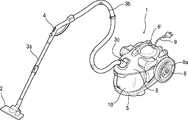
Translated fromKorean도 1은 종래기술에 의한 진공청소기의 사시도.1 is a perspective view of a vacuum cleaner according to the prior art.
도 2는 종래기술에 의한 진공청소기 집진유니트의 사시도.Figure 2 is a perspective view of a vacuum cleaner dust collecting unit according to the prior art.
도 3은 본 발명에 의한 진공청소기의 바람직한 실시예의 구성을 보인 사시도.Figure 3 is a perspective view showing the configuration of a preferred embodiment of a vacuum cleaner according to the present invention.
도 4는 본 발명 실시예을 구성하는 본체의 부분정면도.4 is a partial front view of a main body constituting an embodiment of the present invention;
도 5는 본 발명 실시예를 구성하는 본체로부터 집진유니트가 분리된 상태를 보인 사시도.5 is a perspective view showing a state in which the dust collection unit is separated from the main body constituting the embodiment of the present invention.
도 6은 본 발명 실시예를 구성하는 본체의 분해사시도.Figure 6 is an exploded perspective view of the body constituting the embodiment of the present invention.
도 7은 본 발명 실시예를 구성하는 집진유니트의 분해사시도.Figure 7 is an exploded perspective view of the dust collecting unit constituting the embodiment of the present invention.
도 8은 도 5의 Ⅰ-Ⅰ'의 단면도.8 is a cross-sectional view taken along the line II ′ of FIG. 5;
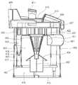
도 9는 본 발명 실시예의 본체 내부구성을 보인 단면도.9 is a cross-sectional view showing the internal structure of the embodiment of the present invention.
도 10은 본 발명 실시예를 구성하는 본체를 이동시키는 상태를 보인 사용상태도.10 is a use state showing a state of moving the main body constituting the embodiment of the present invention.
도 11은 본 발명 실시예을 구성하는 이동핸들의 다른 설치상태를 보인 부분정면도.11 is a partial front view showing another installation state of the moving handle constituting the embodiment of the present invention.
<도면의 주요 부분에 대한 부호의 설명><Explanation of symbols for the main parts of the drawings>
50. 흡입노즐체60. 연장관50.
62. 연장관걸이70. 연결호스62. Extension Hose 70. Connecting Hose
80. 동작핸들82. 조작부80. Operation handle 82. Control panel
90. 커넥터`100. 본체90. Connector `100. Body
110. 제1베이스150. 제2베이스110.
170. 전방서포터200. 커버170.
210. 이동핸들212. 핸들힌지210. Moving
220. 걸이고정부300. 모터하우징220. Hanging
400. 집진유니트400. Dust collection unit
본 발명은 진공청소기에 관한 것으로, 보다 상세하게는 본체에 설치되는 이동핸들이 본체 상측을 돌출되지 않도록 구성되는 진공청소기에 관한 것이다.The present invention relates to a vacuum cleaner, and more particularly, to a vacuum cleaner configured so that the movable handle installed on the main body does not protrude from the upper side of the main body.
도 1에는 일반적인 진공청소기의 구성이 도시되어 있다. 도시된 바와 같이, 진공청소기는, 실내의 공기를 흡입하는 흡입수단이 내장된 본체(1)와, 상기 본체(1)에서 발생하는 흡입력에 의하여 바닥면의 공기가 유입되는 흡입노즐(2)을 포함하는 구성을 가진다. 1 shows a configuration of a general vacuum cleaner. As shown, the vacuum cleaner includes a main body 1 having suction means for sucking air in the room, and a
한편 상기 본체(1)는, 흡입수단이 수납되어 체결되는 하부본체(5)와, 상기 하부본체(5)에 내장된 부품이 외부로 드러나지 않도록 하고, 진공청소기를 제어하 는 전장부(미도시)가 내장되는 상부본체(6)로 구성되어 진다.On the other hand, the main body 1, the
상기 상부본체(6)의 상면에는 이동핸들(6')이 더 구비된다. 상기 이동핸들(6')은 청소기의 이동시 사용자의 파지를 용이하게 하기 위한 것으로, 상기 상부본체(6)의 상면으로부터 상측으로 라운드지게 돌출 형성된다.A moving handle 6 'is further provided on the upper surface of the
또한 상기 본체(1)가 바닥면을 원활하게 이동할 수 있도록 그 본체의 양측면에 바퀴(8)가 체결되고, 상기 바퀴(8)에는 흡입노즐(2)을 통하여 흡입된 공기에서 이물질이 분리된 상태의 공기가 본체(1)에서 토출되는 토출부(8a)가 구성되어 진다.In addition,
그리고 상기 본체(1)와 흡입노즐(2) 사이에는, 플렉시블한 재질의 것으로 만들어지는 흡입호스(3b)와, 상기 흡입호스(3b)의 단부에 연결되는 조작부(82)와, 상기 조작부(82)와 흡입노즐(2)을 연결하는 연장관(3a) 등이 순차적으로 설치되어 있어서, 본체(1)에서 발생하는 흡입력을 상기 흡입노즐(2)로 전달할 수 있게 된다.Between the main body 1 and the
따라서 상기 본체(1)에 내장되어 있는 전장부(미도시)와 연결된 파워코드(9)를 통하여 전기를 인가하면, 진공청소기는 운전대기 상태가 된다. 이때, 사용자가 조작부(82)의 버튼을 이용하여 흡입단계를 조정하면, 각 단계에 적당한 흡입력이 본체(1)에 내장되어 있는 흡입수단에 의하여 발생된다. Therefore, when electricity is applied through the power cord 9 connected to the electric part (not shown) built in the main body 1, the vacuum cleaner is in a standby state. At this time, when the user adjusts the suction step by using the button of the
상기 흡입수단을 통하여 발생된 흡입력은 흡입연결부(3c)에 체결되어 있는 흡입호스(3b) 및 연장관(3a)을 거쳐 흡입노즐(2)로 전달된다. 상기 흡입노즐(2)로 전달된 흡입력에 의하여 먼지나 보푸라기 등의 이물질이 포함된 공기가 흡입되고, 흡입된 공기중의 이물은 집진유니트(10)에 의하여 분리되며, 이물이 필터링된 공기 는 토출부(8a)를 통하여 본체(1) 외부로 토출되는 과정에 의해 청소가 수행된다.The suction force generated through the suction means is transmitted to the
도 2는 종래의 먼지필터(14)가 체결된 상태의 집진유니트(10)를 도시한 것으로, 일측에는 흡입연결부(3c)를 통하여 본체(1)로 유입된 공기가 집진유니트(10) 내벽을 따라 접선방향으로 유동하도록 함으로써 사이클론을 유발하는 흡입가이드(12)가 성형되고, 내부에는 상기 흡입가이드(12)를 통하여 유입된 질량이 큰 먼지가 분리될 수 있도록 구멍(13a)이 성형된 분리판(13)이 조립되고, 상기 흡입가이드(12)의 타측 외벽에는 본체(1)로부터의 착탈을 용이하도록 하는 손잡이(15)가 구비된다.2 shows a
그리고, 집진유니트(10)의 상부를 개폐 가능하도록 구성되는 상면커버(11)에는, 중앙에 토출구(11a)가 성형되고, 상기 토출구(11a)의 저면 가장자리에 먼지필터(14)가 체결된다.The
상기 먼지필터(14)의 필터본체(14b)는 길이방향의 주름이 원주방향으로 반복되게 형성된 원통형상을 가지고 있다. 그리고, 상기 필터본체(14b)의 저부를 고정하여 지지하는 하측고정부(14a) 테두리는 필터본체(14b)의 저부를 감싸도록 상방으로 일정부분 돌출되어 있다.The
상기 먼지필터(14)의 필터본체(14b)는, 공기가 강하게 유동되는 것을 고려하여 일정 이상의 강도가 확보되고 세척시 형태를 유지할 수 있는 재질의 것으로 성형하는 것이 바람직하다. 예를 들면, 섬유재로 활용이 가능한 폴리에스테르 재질로 구성할 수도 있다.The filter
또한 상기 필터본체(14b)의 상부와 저부를 고정하여 지지하는 상측고정부(미 도시)와 하측고정부(14a)도 필터본체(14b)가 원기둥 형태를 유지할 수 있도록 구성됨과 동시에, 세척이 가능한 합성수지재로 구성할 수도 있다.In addition, the upper and lower fixing portions (not shown) and the
상기 필터본체(14b)가 길이방향의 주름이 다수개 성형되는 것에 의하여 유동하는 공기와의 접촉표면적을 넓혀줄 수 있게 되므로, 집진효율이 극대화 된다. 즉, 토출구(11a)를 통하여 배출되는 공기에 미세한 이물질이 포함되지 않도록 상기 필터본체(14b)에 의하여 걸러주게 되는 것이다.Since the filter
이러한 과정을 거치면서 먼지필터(14)의 필터본체(14b) 표면에 미세한 이물질이 쌓이게 되면, 공기의 유동이 원활하게 이루어지지 않게 된다. 따라서, 상기 먼지필터(14)의 표면에 묻어있는 이물질을 털어주거나 세척해야 한다.If fine foreign matters are accumulated on the surface of the
그러나 상기와 같이 구성되는 종래의 진공청소기에서는 공기중의 이물이 상기 먼지필터(14)에 의해 단한번 필터링되므로, 공기의 정화능력이 낮은 문제점이 있다. However, in the conventional vacuum cleaner configured as described above, since foreign matters in the air are filtered only once by the
또한, 상기 상부본체(6)의 상면에는 이동핸들(6')이 상측으로 돌출 형성되어 있으므로, 외관이 수려하지 못하며, 청소 작업시 상기 파워코드(9) 등과 간섭이 생겨 작업에 방해가 되는 문제점이 있다.In addition, since the movable handle 6 'protrudes upward on the upper surface of the
상기와 같은 종래의 문제점을 해결하기 위한 본 발명의 목적은, 공기중의 이물이 이중으로 필터링되는 진공청소기를 제공하는 것이다.An object of the present invention for solving the conventional problems as described above is to provide a vacuum cleaner in which foreign matter in the air is filtered twice.
본 발명의 다른 목적은, 청소기 이동시 사용자가 파지하는 이동핸들이 본체의 상면으로부터 돌출되지 않도록 구비되는 진공청소기를 제공하는 것이다.Another object of the present invention is to provide a vacuum cleaner which is provided such that the moving handle gripped by the user does not protrude from the upper surface of the main body when the cleaner moves.
상기와 같은 목적을 달성하기 위한 본 발명의 진공청소기는, 내부에는 모터와 같은 다수의 부품이 내장되는 본체와; 상기 본체에 안착되고, 싸이클론 유동에 의해서 이중으로 공기중의 이물을 필터링하는 집진유니트와; 상기 본체와 이격되어 바닥면에 근접한 상태로 이동하면서, 공기와 이물의 흡입을 안내하는 흡입노즐체와; 상기 흡입노즐체의 일단에 연결 설치되며, 길이조절이 가능하도록 구성되는 연장관과; 상기 흡입노즐체와 상기 본체 사이에 구비되어, 상기 흡입노즐체를 통해 유입되는 공기와 이물을 안내하는 신축성 재질의 연결호스와; 상기 본체에 설치되어, 상기 본체의 이동을 용이하게 하는 이동핸들을 포함하는 구성을 가지며; 상기 이동핸들은 상기 본체의 외면으로부터 외측으로 돌출되지 않도록 보관되는 것을 특징으로 한다.Vacuum cleaner of the present invention for achieving the above object, the body and a plurality of parts are built-in, such as a motor; A dust collecting unit mounted on the main body and filtering foreign matter in the air by a cyclone flow; A suction nozzle body for guiding suction of air and foreign materials while moving in a state of being spaced apart from the main body and close to the bottom surface; An extension pipe connected to one end of the suction nozzle body and configured to be adjustable in length; A connection hose provided between the suction nozzle body and the main body and configured to guide air and foreign substances introduced through the suction nozzle body; It is installed in the main body, has a configuration including a movement handle to facilitate the movement of the main body; The movable handle is stored so as not to protrude outward from the outer surface of the main body.
이와 같이 구성되는 본 발명에 의하면, 진공청소기의 이물 필터링 능력이 향상되고, 외관이 수려해지는 이점이 있다.According to this invention comprised in this way, there exists an advantage that the foreign material filtering capability of a vacuum cleaner improves and appearance is beautiful.
이하에서는 도면을 참조하여 본 발명의 바람직한 구체적 실시예를 상세하게 설명한다.Hereinafter, exemplary embodiments of the present invention will be described in detail with reference to the accompanying drawings.
도 3은 본 발명에 의한 진공청소기의 바람직한 실시예의 사시도가 도시되어 있다.3 shows a perspective view of a preferred embodiment of the vacuum cleaner according to the invention.
이에 도시된 바와 같이, 본 발명에 의한 진공청소기는, 바닥면에 근접한 상태로 이동하면서 공기와 이물의 흡입을 안내하는 흡입노즐체(50)와, 상기 흡입노즐체(50)의 일단에 연결 설치되며 길이조절이 가능하도록 구성되는 연장관(60)과, 상 기 연장관(60)과 연결되어 상기 흡입노즐체(50)를 통해 유입되는 공기와 이물을 안내하는 신축성 재질의 연결호스(70)와, 상기 연결호스(70)의 일단과 연결되고 다수의 부품이 내장되는 본체(100) 등으로 구성된다.As shown in the drawing, the vacuum cleaner according to the present invention is connected to one end of the
보다 상세하게는 상기 흡입노즐체(50)와 본체(100)는 이격되어 있으며, 이러한 흡입노즐체(50)와 본체(100) 사이에는 상기 연장관(60)과 연결호스(70) 등이 구비되어 공기와 이물의 유동을 안내하게 된다.In more detail, the
한편, 상기와 같은 연장관(60)의 일단(선단)부, 즉 상기 흡입노즐체(50)가 연결되는 부위에는 연장관걸이(62)가 외측으로 돌출 형성된다. 상기 연장관걸이(62)는 아래에서 설명할 본체(100)의 걸이고정부(220)에 삽입되어 걸어지는 부분이다.On the other hand, one end (tip) of the
상기 연장관(60)의 다른 일단(후단)에는 동작핸들(80)이 구비된다. 상기 동작핸들(80)은 사용자가 청소작업시 파지를 용이하게 하는 부분으로, 이러한 동작핸들(80)의 전면에는 사용자가 진공청소기를 조작할 수 있도록 하는 조작부(82)가 형성된다.The other end (rear end) of the
따라서 사용자는 한손으로 상기 동작핸들(80)을 파지한 상태에서 상기 조작부(82)를 조작하여 청소기의 동작여부와 청소기의 강약을 조절할 수 있게 된다.Therefore, the user can control the operation of the cleaner and the strength of the cleaner by manipulating the
상기 본체(100)와 연결호스(70)의 연결 부위에는 커넥터(90)가 더 구비된다. 상기 커넥터(90)는 상기 조작부(82)로부터 입력된 사용자의 조작 신호가 상기 본체(100)로 인가되도록 하기 위한 연결단자의 기능과, 상기 연결호스(70)를 통해 유입되는 공기를 상기 본체(100)로 안내하는 기능을 동시에 수행한다.The
따라서 도시되지는 않았지만, 상기 커넥터(90)의 단부에는 복수개의 전기 연결단이 더 구비되며, 이러한 커넥터(90)는 상기 동작핸들(80)에 상기 조작부(82)가 구비되는 경우와 같이 조작부(82)가 상기 본체(100) 외에 구비되는 경우에 전기 연결단을 포함한다.Therefore, although not shown, a plurality of electrical connection ends are further provided at the end of the
즉, 상기 조작부(82)가 상기 본체(100)의 어느 곳에 구비되는 경우에는 상기 커넥터(90)에는 전기 연결단이 구비되지 아니하고 공기의 유입통로로서의 기능만이 수행되도록 구성된다.That is, when the
상기 본체(100)에는, 상기 본체(100)의 바닥면에 제공되는 제1베이스(110)와, 상기 제1베이스(110)의 직근 상측에 놓이는 제2베이스(150)와, 상기 본체(100) 뒷쪽편의 양측에 제공되어 상기 본체(100)의 이동이 원활하게 수행되도록 하는 바퀴(111)와, 상기 본체(100)의 상부 외관을 형성하는 커버(200)와, 상기 본체(100)의 전방부에서 상기 커버(200)와 상기 베이스(110)(150)가 연결되어 양자가 견고하게 결합 지지되도록 하는 전방서포터(170) 등이 구비된다.The
상기 전방서포터(170)에는 상기 커넥터(90)가 연결되어 외기가 흡입되도록 하는 것은 물론이다. 그리고, 상기 전방서포터(170)는 상기 본체(100) 앞쪽 부분이 원래의 형상대로 견고하게 지지되도록 한다.Of course, the
상기 제2베이스(150)는 상기 제1베이스(110)의 직근 상방에 제공되어 진공청소기의 외관이 미려하게 되고, 상기 본체(100)의 하측부의 강도가 증가하여 외부 충격에 대해서 견고하게 지지되도록 한다.The
상기 커버(200)의 후방에는 본체 배기구(302)가 형성되는 배기커버(301)가 제공되어, 상기 본체(100)에 의해서 깨끗해진 공기가 배출된다. 그리고, 상기 본체(100)의 상면에는 이동핸들(210)이 구비된다.An
상기 이동핸들(210)은 사용자가 진공청소기의 본체(100)를 이동하고자 하는 경우에 파지를 용이하게 하기 위한 것으로, 선단부에 형성되는 핸들힌지(212)를 축으로 회동 가능하게 설치된다. 그리고 상기 핸들힌지(212)는 상기 본체(100)의 상면으로부터 상측으로 돌출되지 않도록 보관된다.The movement handle 210 is for facilitating the gripping when the user wants to move the
보다 상세하게는 상기 이동핸들(210)은 상기 커버(200)의 상면에 설치된다. 즉, 상기 커버(200) 상면에 상기 핸들힌지(212)가 구비되고, 상기 이동핸들(210)은 이러한 핸들힌지(212)를 축으로 회동 가능하도록 설치된다.In more detail, the
그리고 도 4에 도시된 바와 같이, 상기 이동핸들(210)이 상기 커버(200)에 접촉한 상태에서는 상기 이동핸들(210)의 상면이 상기 커버(200)의 상면 상측으로 돌출되지 않도록 구성된다. 보다 상세하게는 상기 본체(100) 상면, 즉 상기 커버(200)의 상면과 상기 이동핸들(210)의 상면이 동일 평면을 이루도록 구성된다.As shown in FIG. 4, in the state where the
보강 설명하면, 상기 이동핸들(210)은 상기 본체(100)를 이동시키고자 할 때에는 직립되어 사용되고, 보관시에는 뉘어져 있게 되는데, 이처럼 상기 이동핸들(210)이 뉘어져 있는 경우에는 이동핸들(210)의 상면과 상기 본체(100)의 상면이 동일 평면상에 위치되도록 구성된다. 물론 이때 상기 본체(100)의 상면이 일정한 곡률을 가지도록 라운드지게 형성되는 경우에는 상기 이동핸들(210)의 상면도 본체(100)의 상면과 대응되는 곡률을 가지도록 형성됨이 바람직하다.Reinforcement description, the moving
상기 커버(200)의 후면에는 걸이고정부(220)가 후방으로 돌출 형성된다. 상 기 걸이고정부(220)는 상기 연장관걸이(62)가 걸어져 고정되는 부분이다. 즉, 상기 연장관(60)이 사용되지 않는 경우에는 상기 연장관걸이(62)를 상기 걸이고정부(220)에 삽입하여 보관한다.The rear side of the
상기 전방서포터(170)의 후방에는 집진유니트(400)가 안착되어 외기가 유입되고, 상기 집진유니트(400)의 내부에는 싸이클론 유동에 의해서 이물이 걸러지도록 하는 싸이클론 부재가 수용된다.At the rear of the
한편, 도 5에 제시되는 바와 같이, 상기 집진유니트(400)는 상기 본체(100) 내부의 집진유니트 수용부(151)에 상하 방향으로 안착된다. 그러므로, 상기 집진유니트 수용부(151)의 내부에서 장착시에는 하방으로 누르고, 탈거시에는 상측으로 당기면 된다.On the other hand, as shown in Figure 5, the
상기 전방서포터(170)에는 본체 흡입구(171)가 형성되고, 상기 본체 흡입구(171)와 정렬되는 상기 집진유니트(400)의 대응되는 위치에는 집진유니트 흡입구(401)가 위치한다. 그리고, 집진유니트(400)에서 상기 집진유니트 흡입구(401)와 반대되는 방향에는 배출구가 형성된다. 상기 배출구는 모터측 흡입구(172)와 정렬되어, 집진유니트(400)를 통과하는 중에 깨끗해진 공기가 모터측으로 흡입되도록 한다.The
특히, 상기 배출구와 상기 모터측 흡입구(172)는 상기 본체(100)의 크기를 줄이고 공기가 원활히 유동되도록 하기 위하여 납작한 직 사각형의 형상으로 제공된다.In particular, the outlet and the
도 6는 본 발명에 따른 진공청소기 본체의 분해 사시도이다.6 is an exploded perspective view of a vacuum cleaner body according to the present invention.
도 6를 참조하면, 상기 제1베이스(110) 상측부의 전방부에는 상기 제2베이스(150)가 놓이고, 뒷쪽에는 모터하우징(300)이 놓인다. 그리고, 그 상측에는 순차적으로 상기 커버(200)가 덮혀져서 상기 본체(100)가 이루어진다.Referring to FIG. 6, the
여기서, 상기 커버(200)는, 상기 전방서포터(170)가 별도의 부분으로서 상기 커버(200)에 체결된 상태에서 상기 베이스(110)(150)에 결합된다. 그리고, 상기 모터하우징(300)에서는 상기 모터측 흡입구(172)를 통하여 흡입된 공기의 유동 방향이 수직으로 꺾여서 하방으로 유입된다. 그리고, 유입된 공기는 모터하우징(300)에서 유동 방향이 수평으로 다시금 꺾여서 후방으로 배출되도록 한다. 상기 모터하우징(300)의 내부에 모터가 수용되는 것은 물론이다.Here, the
도 7는 본 발명에 따른 집진유니트의 분해 사시도이다.7 is an exploded perspective view of the dust collecting unit according to the present invention.
도 7를 참조하면, 본 발명의 집진유니트(400)는 스펀지등과 같은 다공성 필터가 사용되지 아니하고, 싸이클론 유동에 의해서 이물이 걸러지도록 한다. 그리고, 상기 싸이클론 유동은 서로 분리되는 두 개소 이상의 분리챔버에서 각각 수행되도록 하여, 공기 중의 미세먼지까지 완전하게 필터링되도록 하는 것에 일 특징이 있다.Referring to FIG. 7, the
상세하게 설명하면, 복수 개의 이물분리챔버(도 8의 423, 424참조, 이하 분리챔버라고도 한다.)와, 복수개의 이물저장챔버(도 8의 416, 417참조, 이하 저장챔버라고도 한다.)가 형성되는 집진바디(406)와, 상기 집진바디(406)의 하측부에 밀폐로 제공되어, 상기 이물저장챔버(416)(417)에 저장되는 이물이 누설되지 않도록 하는 챔버 실링부(415)(402)와, 상기 집진바디(406)의 상방에 놓여서 상기 집진바 디(406)에서 배기되는 공기의 유동이 가이드되는 배기부(407)와, 상기 배기부(407)의 상방에 소정의 간격으로 제공되어 배기부(407)를 통과한 공기가 일 방향으로 향하도록 하는 간격부(408)와, 상기 간격부(408)의 상방에 놓이는 커버구조(409)(410)(411)(412)가 포함된다.In detail, a plurality of foreign material separation chambers (see 423 and 424 of FIG. 8, hereinafter also referred to as separation chambers) and a plurality of foreign material storage chambers (see 416 and 417 of FIG. 8, also referred to as storage chambers hereinafter). The
상세하게, 상기 커버구조는 모체를 이루는 제 1 커버(410)와, 상기 제 1 커버(410)의 전방 및 후방에 각각 놓이는 제 3 커버(412) 및 제 2 커버(409)와, 상기 제 1 커버(410)와 제 2 커버(409)가 같이 고정되도록 하는 커버 삽지구(411)가 포함된다. 상기 커버 삽지구(411)는 상기 제 1 커버(410) 상면부의 일부분을 덮어서 외관이 아름답게 구현되고, 상기 제 1 커버(410) 및 제 2 커버(409)가 동시에 고정되도록 하는 기능이 수행된다.In detail, the cover structure includes a
상기 집진바디(406)의 내부에는, 싸이클론 유동에서 오물 분리가 원활히 수행되도록 하는 원추형 필터(405)와, 상기 원추형 필터(405)의 하방에 놓여서 포집된 이물의 재비산을 방지하는 차단부(404)와, 상기 차단부(404)의 하방에 형성되어 회전운동되는 공기의 유속을 느리게 하여, 이물이 저장챔버의 내부에 가라앉도록 하는 유동방지판(403)이 더 형성된다.Inside the
여기서, 상기 차단부(404)와 상기 유동방지판(403)은 한 몸으로 형성되고, 상기 원추형 필터(405)는 별도의 부품으로 형성될 수 있다. 이와 같이, 상기 차단부(404)가 별도의 물품으로서 상기 원추형 필터(405)에 추가적으로 끼워져서 장착될 수 있기 때문에, 상기 원추형 필터(405)에 이물질이 끼었을 때에는 차단부(404)를 원추형 필터(405)에서 탈거한 뒤에, 원추형 필터(405)의 벽면에 붙어있는 이물 을 편리하게 제거할 수 있다.Here, the blocking
상세하게는, 머리카락이나 종이등과 같은 이물질이 외부에서 흡입되었을 때에는, 원추형 필터(405)의 외벽에 붙어서 흡입력을 급감시키게 된다. 이때에는, 사용자가 이를 제거해서 원래의 상태로 원추형 필터(405)를 깨끗하게 해야만 되는데, 이때에는 상기 차단부(404)를 원추형 필터(405)에서 분리한 뒤에, 손을 원추형 필터(405)쪽으로 넣어서 머리카락등을 편리하게 제거할 수 있는 것이다. 그리고, 상기 원추형 필터(405)는 하측의 직경이 좁기 때문에, 머리카락등을 하방으로 당기기만 하면 편리하게 이물이 제거된다.In detail, when foreign matter such as hair or paper is sucked from the outside, the suction force is drastically reduced by sticking to the outer wall of the
또한, 상기 제 1 커버(410)의 일측부에는 개폐버튼(413)이 놓인다. 그리고, 상기 개폐버튼(413)과 일단이 닿아서 상기 개폐버튼(413)의 푸쉬 동작에 의해서 회동운동이 수행되는 개폐레버(414)가 형성된다. 또한, 상기 개폐레버(414)의 타단은 상기 제 1 챔버 실링부(415)와 닿는다. 그러므로, 상기 개폐버튼(413)의 누르는 동작에 의해서, 상기 개폐레버(414)는 소정의 힌지점을 중심으로 회전된다. 그리고, 상기 개폐레버(414)의 타단부에서, 상기 제 1 챔버 실링부(415)와 상기 개폐레버(414)와의 접촉이 떨어지면, 상기 제 1 챔버 실링부(415)는 자중에 의해서 힌지점을 중심으로 회전되고, 상기 이물저장챔버(416)(417)의 내부에 포집되어 있던 이물은 자중에 의해서 낙하되어 폐기된다.In addition, an opening and
또한, 상기 챔버 실링부(415)(402)에 의해서 각각의 대응되는 저장챔버(415)(416)의 하측면이 밀폐 실링된다. 그리고, 상기 제 1 챔버 실링부(415)는 상기 집진바디(406)에 힌지결합되고, 이물의 폐기시에 제 1 챔버 실링부(415)가 힌지 운동에 의해서 열려서 이물이 손쉽게 버려질 수 있도록 한다. 그리고, 상기 집진바디(406)의 상면에는 제 1 이물분리챔버(423)와 제 2 이물분리챔버(424)를 구획하고 유로를 형성하는 분리판(437)이 형성된다.In addition, the lower surfaces of the corresponding
또한, 상기 집진바디(406)의 외측면에는 상기 배기부(407)가 집진바디(406)의 바깥쪽으로 안착될 때 위치가 용이하게 찾아지고, 삽입 동작이 원활히 수행되도록 하기 위한 다수개의 가이드 리브(459)가 형성된다. 그리고, 상기 가이드 리브(459)의 상측모서리 부위는 부드럽게 만곡되도록 하여, 배기부(407)의 삽입동작이 손쉽게 수행되도록 한다.In addition, the outer surface of the
도 8은 도 5의 Ⅰ-Ⅰ'의 단면도로서, 도 8을 참조하여, 집진유니트(400)의 내부 구성 및 집진유니트의 동작을 상세하게 설명한다.FIG. 8 is a cross-sectional view taken along line II ′ of FIG. 5, with reference to FIG. 8, which describes the internal structure of the
먼저, 상기 도 7에서 상세하게 설명된 바와 같이, 본 발명에 따른 집진유니트(400)에는, 집진바디(406)와, 상기 집진바디(406)의 하측을 선택적으로 밀폐시키는 실링부(402)(415)와, 상기 집진바디(406)의 내부에 수용되어 집진효율을 증대시키는 원추형 필터(405)와, 포집된 이물의 재비산을 막는 차단부(404)와, 싸이클론 유동의 유속이 저하되어 이물이 낙하되도록 하고, 먼지의 들뜸을 방지하는 유동방지판(403)과, 상기 집진바디(406)의 상측에 놓여서 상기 집진바디(406)로부터 배기되는 공기가 원활히 유동되도록 하는 배기부(407)와, 상기 배기부(407)를 경유한 공기가 일방향으로 모이도록 하는 간격부(408)와, 상기 배기부(407)의 상측부에 놓이는 커버(409)(410)(411)(412)가 포함된다.First, as described in detail with reference to FIG. 7, the
상기 집진바디(406)의 구성을 설명한다.The configuration of the
상기 집진바디(406)는 상하로 연장되는 복수개의 벽이 제공되는데, 최외각에 형성되는 외벽(418)과, 상기 외벽(418)의 안쪽에 형성되는 중간벽(419)과, 상기 중간벽(419)의 안쪽에 형성되는 내벽(420)이 포함된다. 그리고, 상기 중간벽(419) 및 내벽(420)은, 상기 집진유니트측 흡입구(401)가 통과되는 간격에는 형성되지 않도록 함으로써, 원활하게 공기가 유입되도록 한다.The
상기 외벽(418) 및 중간벽(419)의 사이 공간은 제 1 이물저장챔버(416)가 되고, 상기 중간벽(419)과 상기 내벽(420)의 사이 공간은 제 2 이물저장챔버(417)가 되고, 상기 내벽(420)의 내부 공간은 제 1 이물분리챔버(423)가 된다. 다만, 구체적으로 집진유니트(400)의 형태에 따라서, 공간의 사용상의 목적은 달라질 수 있을 것이다.The space between the
상기되는 구성에 의한 작용 내지 동작을 공기의 유동순서를 기준으로 상세하게 설명한다. 먼저, 공기는 상기 집진유니트측 흡입구(401)를 통하여 집진유니트(400)의 내부로 유입된다. 여기서, 상기 집진유니트측 흡입구(401)는 외측으로는 상기 전방서포터(170)와 접하고, 내측으로는 상기 제 1 이물분리챔버(423)와 연통되어 외기가 유입된다. 그리고, 상기 집진유니트측 흡입구(401)의 내측에는 공기의 유동방향을 상기 제 1 이물분리챔버(423)의 내주면 방향으로 안내하기 위하여, 제 1 유입 가이드(421)가 상기 내벽(420)에서 안쪽으로 돌출되어 있다.The operation or operation by the above-described configuration will be described in detail based on the flow order of air. First, air is introduced into the
상기 제 1 이물분리챔버(423)의 내부에서 공기가 싸이클론 유동하는 중에, 이물은 하방으로 낙하되고 깨끗한 공기는 원추형 필터(405)의 개공을 통과하여 상측방향으로 배출된다. 이와 같이 원추형 필터(405)가 적용되는 것은, 집진유니트측 흡입구(401)가 상측에 위치하기 때문에 원추형 필터(405)의 상측부에는 비교적 고속회전의 싸이클론 유동이 일어나고, 하측부에는 비교적 저속의 싸이클론 유동이 일어나기 때문이다. 즉, 고속의 싸이클론 유동에서는 이물이 외측으로 좀더 많이 치우쳐서 회전되지만, 저속의 싸이클론 유동에서는 이물이 내측으로 좀더 많이 퍼진 상태이기 때문에, 이물이 걸러지도록 하기 위해서는, 필터 부재가 원추형으로 적용되는 것이 바람직하다.During the cyclone flow of air in the first foreign
상기 원추형 필터(405)는 제 1 분리챔버(423)의 상면벽을 이루는 분리판(437)의 중심부에 안착되고, 상기 분리판(437)에서 선택적으로 분리가 가능한 구조로 제공될 수도 있다. 그리고, 상기 원추형 필터(405)에는 다수의 개공이 형성되어 공기가 외부로부터 통과하여 안쪽으로 유입되는 것은 물론이다.The
여기서, 낙하된 이물의 재비산이 방지되기 위하여 상기 원추형 필터(405)의 하측에는 차단부(404)가 놓이고, 도시되는 바와 같이 상기 차단부(404)는 하방으로 갈수록 지름이 확장됨으로써, 이물의 재비산이 차단되어 들뜨지 않도록 한다. 또한, 상기 차단부(404)의 하방에는 유동방지판(403)이 일정간격으로 형성되어, 일단 포집된 이물에 대해서는 싸이클론 공기 유동이 도달되지 않도록 함으로써, 이물이 들뜨는 현상이 원천적으로 없어지도록 한다.Here, the blocking
상기 제 1 분리챔버(423)의 내부에서 걸러진 이물은 하측방향에 형성되는 제 1 저장챔버(416)에 저장된다. 여기서, 저장된 이물의 누설이 방지되도록 하기 위하여, 상기 제 1 저장챔버(416)의 하단부에는 제 1 챔버실링부(415)가 놓인다.The foreign material filtered in the
한편, 상기 원추형 필터(405)를 통과하여 분리판(437)의 상측으로 유입된 공 기는 큰 이물은 걸러진 상태이다. 그러므로, 이차적으로 미세한 이물이 걸러지도록 하는 싸이클론 유동이 더 필요하게 된다. 이하에서는 더 수행되는 싸이클론 유동에 대해서 상세하게 설명한다.On the other hand, the large amount of foreign matter is filtered out of the air flowing through the
상기 원추형 필터(405)를 통과한 공기는 제 2 유입가이드(422)를 통하여 제 2 분리챔버(424)의 내부로 유입된다. 또한, 상기 제 2 유입가이드(422)는 상기 제 2 분리챔버(424)의 내주면을 접선방향으로 향하도록 하기 때문에, 제 2 분리챔버(424)의 내부로 유입되는 공기는 챔버의 내부에서 싸이클론 유동된다.Air passing through the
상기 제 2 이물분리챔버(424)의 내부에서 싸이클론 유동에 의해서 분리되는 이물은 하방으로 낙하되어 제 2 이물저장챔버(417)에 저장된다. 그리고, 낙하된 이물이 다시금 비산되지 않도록 하기 위하여, 상기 제 2 이물분리챔버(424)의 하측부는 점진적으로 수축되어 있다. 그리고, 상기 제 2 이물저장챔버(417)의 내부에 포집되는 이물이 누설되지 않도록 하기 위하여, 상기 제 2 이물저장챔버(417)의 하측부는 제 2 챔버실링부(402)에 의해서 밀폐된다.The foreign matter separated by the cyclone flow in the second foreign
여기서, 상기 제 2 챔버실링부(402)는 바 형태의 연결구조에 의해서 상기 제 1 챔버실링부(415)와 결합되어 있다. 이와 같이, 상기 제 1 챔버실링부(415)와 제 2 챔버실링부(402)가 바 형태의 연결구조에 의해서 연결되는 것은, 상기 제 1 이물저장챔버(416)의 내부용적을 크게 하기 위한 것이다. 다시 말하면, 상기 제 2 챔버실링부(402)의 하단에서 제 1 챔버실링부(415) 상단까지의 이격되는 공간에는 이물이 저장되기 때문에, 이물이 보다 많이 수용되도록 하기 위해서는 바 형태와 같은 작은 공간을 차지하는 부재에 의해서 연결되는 것이 바람직한 것이다.Here, the second
상기 제 2 이물분리챔버(424)의 내부에서 이물이 걸러진 뒤에는 배기부측 흡입구(425)를 경유하여 배기부(407)로 유입되어, 상기 배기부(407)와 간격부(408)의 사이 간격에 해당되는 공간에 모인다. 여기서, 상기 배기부측 흡입구(425)의 직경은 상기 제 2 이물분리챔버(424)의 내경보다 축소되는데, 이와 같은 직경의 관계로 인하여 제 2 이물분리챔버(424)의 이물이 상기 배기부(407)로 함께 유동할 가능성은 더욱 줄어드는 장점을 얻을 수 있다. 다시 말하면, 상기 제 2 이물분리챔버(424)의 내면에 모여있는 이물은 상기 배기부측 흡입구(425)를 통하여 유출되지 않게 되는 것이다.After the foreign material is filtered inside the second foreign
설명된 바와 같이, 두 군데의 싸이클론 유동에 의해서 이물이 걸러진 공기는, 상기 모터측 흡입구(172)를 통하여 모터로 유입된다. 그리고, 모터를 통과한 뒤에는 상기 본체(100)의 후면으로 배기된다.As described, air filtered by foreign matter by two cyclone flows is introduced into the motor through the
한편, 상기 간격부(408)의 상측부에는 소정의 커버구조가 더 형성된다. 상세하게는, 전체적인 커버구조를 이루는 제 1 커버(410)와, 상기 제 1 커버(410)의 전방 및 후방을 보호하는 제 3 커버(412) 및 제 2 커버(409)와, 상기 제 1 커버(410)에 상기 제 2 커버(409)가 고정되도록 하는 커버 삽지구(411)가 제공된다.Meanwhile, a predetermined cover structure is further formed on the upper portion of the
상기되는 집진유니트(400)의 동작과 함께 상기 본체(100)의 전체적인 동작 내지 작용을 도 9에 제시되는 진공청소기의 세로 단면도를 참조하여 상세하게 설명한다.The overall operation to the operation of the
도 9를 참조하면, 외기는 커넥터(90)와 연결되는 본체측 흡입구(171)를 통하여 상기 본체(100)로 유입되고, 집진유니트측 흡입구(401)를 통하여 집진유니트 (400)의 내부로 유입된다. 그리고, 집진유니트(400)의 내부에서는 이미 설명된 바와 같은 동작 및 작용에 의해서 이물이 걸러진 뒤에, 모터측 흡입구(172)를 통하여 모터하우징(300)의 내부로 유입된다.Referring to FIG. 9, outside air flows into the
이때, 상기 모터하우징(300)은 수직으로 세워진 상태에서 유입구는 상방을 향하고 있다. 그러므로, 상기 집진유니트(400)를 통과하여 수평으로 유입된 공기는 진행방향이 꺾여서 하방으로 향하게 된다. 그리고, 상기 모터하우징(300)을 통과한 뒤에는, 상기 본체(100)의 배면에 제공되는 본체 배기구(302)를 통하여 외부로 배출된다.At this time, the inlet is directed upward in the state in which the
한편, 상기의 이동핸들(210)은 사용자가 상기 본체(100)를 이동하고자 하는 경우에 사용하게 되는데, 이때에는 도 10과 같이 상기 이동핸들(210)을 상기 핸들힌지(212)를 축으로 회동한 상태에서 손으로 파지한다.On the other hand, the movement handle 210 is used when the user wants to move the
보다 상세하게는 먼저 상기 이동핸들(210)이 도 3과 같이 누워져 있는 상태에서 중앙부를 들어올린다. 이렇게 되면 상기 이동핸들(210)은 핸들힌지(212)를 축으로 반시계방향으로 회동하여 도 10과 같이 직립한 상태가 되고, 이때 사용자는 손으로 상기 이동핸들(210)을 파지하여 상기 본체(100)를 들어올린다.In more detail, first, the moving
그리고 사용후에는 상기 이동핸들(210)을 다시 상기 본체(100)의 상면에 밀착시킨다. 이렇게 되면, 상기와는 반대로 상기 이동핸들(210)이 상기 핸들힌지(212)를 축으로 시계방향으로 회동하여 상기 도 3과 같이 되고, 이때에는 상기 이동핸들(210)의 상면과 상기 본체(100)의 상면이 동일 평면상에 위치하게 되는 것이다.After use, the moving
이러한 본 발명의 범위는 상기에서 예시한 실시예에 한정되지 않고, 상기와 같은 기술범위 안에서 당업계의 통상의 기술자에게 있어서는 본 발명을 기초로 하는 다른 많은 변형이 가능할 것이다.The scope of the present invention is not limited to the above-exemplified embodiments, and many other modifications based on the present invention will be possible to those skilled in the art within the above technical scope.
예를 들어, 상기의 실시예에서는 상기 이동핸들(210)이 누워져 있는 상태에서는 상기 이동핸들(210)의 상면과 상기 본체(100)의 상면이 동일 평면상에 위치하게 되는 경우를 예시하고 있으나, 상기 이동핸들(210)의 상면 위치가 상기 본체(100)의 상면 위치보다 하측에 위치되도록 구성할 수 있음은 물론이다.For example, in the above exemplary embodiment, the upper surface of the moving
또한 상기의 실시예에서는 상기 이동핸들(210)이 눕혀지는 상태에서는 도 3과 같이 상기 본체(100)의 후단에 위치되고 있으나, 이러한 이동핸들(210)의 위치가 본체(100)의 상면 후단에 위치되지 않고 중앙부분에 위치되는 등 다른 부분에 위치되도록 구성될 수도 있다.In addition, in the above embodiment, the
즉, 도 11과 같이 상기 이동핸들(210)이 상기 본체(100) 상면에 눕혀진 경우에, 상기 본체(100)의 상면 후단부에 위치되지 않고 후단으로부터 소정 거리 이격된 부분에 위치되도록 구성할 수 있다. 물론 이때에는 상기 이동핸들(210)의 외면은 상기 본체(100)의 상면과 대응되는 곡률을 가지도록 형성됨이 바람직하다.That is, when the
상기와 같은 본 발명에 의한 진공청소기에서는, 외부로부터 흡입되는 공기중의 이물이 싸이클론 유동에 의해 이중으로 필터링된다. 따라서 진공청소기의 공기 정화능력(이물 필터링 능력)이 향상되는 이점이 있다.In the vacuum cleaner according to the present invention as described above, foreign matter in the air sucked from the outside is double filtered by the cyclone flow. Therefore, there is an advantage that the air purification capacity (foreign material filtering ability) of the vacuum cleaner is improved.
뿐만 아니라, 본 발명에서는 본체에 구비되는 이동핸들이 본체의 외측으로 돌출되지 않도록 구성된다. 따라서 전체적으로 진공청소기의 외관이 수려해지는 이점이 있으며, 이동핸들에 의해 청소작업이 방해받지 않게 되므로, 작업능률이 향상되는 효과가 있다.In addition, in the present invention, the moving handle provided in the main body is configured not to protrude to the outside of the main body. Therefore, there is an advantage that the appearance of the vacuum cleaner as a whole is beautiful, and since the cleaning operation is not disturbed by the moving handle, there is an effect of improving the work efficiency.
Claims (5)
Translated fromKoreanPriority Applications (1)
| Application Number | Priority Date | Filing Date | Title |
|---|---|---|---|
| KR1020050041157AKR100713272B1 (en) | 2005-05-17 | 2005-05-17 | Vacuum cleaner |
Applications Claiming Priority (1)
| Application Number | Priority Date | Filing Date | Title |
|---|---|---|---|
| KR1020050041157AKR100713272B1 (en) | 2005-05-17 | 2005-05-17 | Vacuum cleaner |
Publications (2)
| Publication Number | Publication Date |
|---|---|
| KR20060118803A KR20060118803A (en) | 2006-11-24 |
| KR100713272B1true KR100713272B1 (en) | 2007-05-04 |
Family
ID=37705756
Family Applications (1)
| Application Number | Title | Priority Date | Filing Date |
|---|---|---|---|
| KR1020050041157AExpired - Fee RelatedKR100713272B1 (en) | 2005-05-17 | 2005-05-17 | Vacuum cleaner |
Country Status (1)
| Country | Link |
|---|---|
| KR (1) | KR100713272B1 (en) |
Families Citing this family (22)
| Publication number | Priority date | Publication date | Assignee | Title |
|---|---|---|---|---|
| CA2599303A1 (en) | 2007-08-29 | 2009-02-28 | Gbd Corp. | Surface cleaning apparatus |
| US10165912B2 (en) | 2006-12-15 | 2019-01-01 | Omachron Intellectual Property Inc. | Surface cleaning apparatus |
| US9888817B2 (en) | 2014-12-17 | 2018-02-13 | Omachron Intellectual Property Inc. | Surface cleaning apparatus |
| CN101939110B (en) | 2007-12-19 | 2015-01-21 | Gbd公司 | Structure of cyclone separator assembly and surface cleaning device having said cyclone separator assembly |
| US12156626B2 (en) | 2009-03-13 | 2024-12-03 | Omachron Intellectual Property Inc. | Surface cleaning apparatus |
| US10722086B2 (en) | 2017-07-06 | 2020-07-28 | Omachron Intellectual Property Inc. | Handheld surface cleaning apparatus |
| US9456721B2 (en) | 2013-02-28 | 2016-10-04 | Omachron Intellectual Property Inc. | Surface cleaning apparatus |
| US11950745B2 (en) | 2014-12-17 | 2024-04-09 | Omachron Intellectual Property Inc. | Surface cleaning apparatus |
| US10136778B2 (en) | 2014-12-17 | 2018-11-27 | Omachron Intellectual Property Inc. | Surface cleaning apparatus |
| US10251519B2 (en) | 2014-12-17 | 2019-04-09 | Omachron Intellectual Property Inc. | Surface cleaning apparatus |
| US10631693B2 (en) | 2017-07-06 | 2020-04-28 | Omachron Intellectual Property Inc. | Handheld surface cleaning apparatus |
| US10537216B2 (en) | 2017-07-06 | 2020-01-21 | Omachron Intellectual Property Inc. | Handheld surface cleaning apparatus |
| US10750913B2 (en) | 2017-07-06 | 2020-08-25 | Omachron Intellectual Property Inc. | Handheld surface cleaning apparatus |
| US10506904B2 (en) | 2017-07-06 | 2019-12-17 | Omachron Intellectual Property Inc. | Handheld surface cleaning apparatus |
| US10702113B2 (en) | 2017-07-06 | 2020-07-07 | Omachron Intellectual Property Inc. | Handheld surface cleaning apparatus |
| US10842330B2 (en) | 2017-07-06 | 2020-11-24 | Omachron Intellectual Property Inc. | Handheld surface cleaning apparatus |
| US11930987B2 (en) | 2018-04-20 | 2024-03-19 | Omachron Intellectual Property Inc. | Surface cleaning apparatus |
| US10827889B2 (en) | 2018-05-30 | 2020-11-10 | Omachron Intellectual Property Inc. | Surface cleaning apparatus |
| US10932634B2 (en) | 2018-05-30 | 2021-03-02 | Omachron Intellectual Property Inc. | Surface cleaning apparatus |
| US11006799B2 (en) | 2018-08-13 | 2021-05-18 | Omachron Intellectual Property Inc. | Cyclonic air treatment member and surface cleaning apparatus including the same |
| US11013384B2 (en) | 2018-08-13 | 2021-05-25 | Omachron Intellectual Property Inc. | Cyclonic air treatment member and surface cleaning apparatus including the same |
| US11192122B2 (en) | 2018-08-13 | 2021-12-07 | Omachron Intellectual Property Inc. | Cyclonic air treatment member and surface cleaning apparatus including the same |
Citations (2)
| Publication number | Priority date | Publication date | Assignee | Title |
|---|---|---|---|---|
| KR20020088983A (en)* | 2001-05-22 | 2002-11-29 | 주식회사 엘지이아이 | Accessories custody structure of vacuum cleaner |
| KR20050041157A (en)* | 2003-10-30 | 2005-05-04 | 삼성에스디아이 주식회사 | Image processing method for display panel |
- 2005
- 2005-05-17KRKR1020050041157Apatent/KR100713272B1/ennot_activeExpired - Fee Related
Patent Citations (2)
| Publication number | Priority date | Publication date | Assignee | Title |
|---|---|---|---|---|
| KR20020088983A (en)* | 2001-05-22 | 2002-11-29 | 주식회사 엘지이아이 | Accessories custody structure of vacuum cleaner |
| KR20050041157A (en)* | 2003-10-30 | 2005-05-04 | 삼성에스디아이 주식회사 | Image processing method for display panel |
Non-Patent Citations (2)
| Title |
|---|
| 1020020088983 * |
| 1020050041157 - 720269 * |
Also Published As
| Publication number | Publication date |
|---|---|
| KR20060118803A (en) | 2006-11-24 |
Similar Documents
| Publication | Publication Date | Title |
|---|---|---|
| KR100709417B1 (en) | Vacuum cleaner | |
| KR100709418B1 (en) | Vacuum cleaner | |
| KR100713272B1 (en) | Vacuum cleaner | |
| KR100713285B1 (en) | Vacuum cleaner | |
| KR100697429B1 (en) | Vacuum cleaner | |
| KR100633605B1 (en) | Dust collection unit of vacuum cleaner | |
| KR100553042B1 (en) | Dust collection unit of vacuum cleaner | |
| KR100677982B1 (en) | Motor filter seating structure of vacuum cleaner | |
| KR100963337B1 (en) | Dust collection assembly of vacuum cleaner | |
| KR20050104613A (en) | A dust collector for vacuum cleaner | |
| KR100575319B1 (en) | Dust collection unit of vacuum cleaner | |
| KR100693571B1 (en) | Vacuum cleaner | |
| KR100603523B1 (en) | Vacuum cleaner | |
| KR20060086088A (en) | Dust collection unit of vacuum cleaner | |
| KR100676531B1 (en) | Dust collection unit switchgear of vacuum cleaner | |
| KR100553043B1 (en) | Dust collection unit of vacuum cleaner | |
| KR100548933B1 (en) | Suction structure of vacuum cleaner | |
| KR100564443B1 (en) | Dust collector of vacuum cleaner and vacuum cleaner | |
| KR100569351B1 (en) | Nozzle Parking Structure of Vacuum Cleaner | |
| KR100831777B1 (en) | Dust collection assembly of vacuum cleaner | |
| KR100676533B1 (en) | Euro structure of vacuum cleaner | |
| KR100553044B1 (en) | Dust collection unit of vacuum cleaner | |
| KR100676532B1 (en) | Cover structure of dust collection unit | |
| KR100709403B1 (en) | Handle structure of vacuum cleaner | |
| KR100596251B1 (en) | Dust collection unit of vacuum cleaner |
Legal Events
| Date | Code | Title | Description |
|---|---|---|---|
| A201 | Request for examination | ||
| PA0109 | Patent application | St.27 status event code:A-0-1-A10-A12-nap-PA0109 | |
| PA0201 | Request for examination | St.27 status event code:A-1-2-D10-D11-exm-PA0201 | |
| E902 | Notification of reason for refusal | ||
| PE0902 | Notice of grounds for rejection | St.27 status event code:A-1-2-D10-D21-exm-PE0902 | |
| T11-X000 | Administrative time limit extension requested | St.27 status event code:U-3-3-T10-T11-oth-X000 | |
| PG1501 | Laying open of application | St.27 status event code:A-1-1-Q10-Q12-nap-PG1501 | |
| P11-X000 | Amendment of application requested | St.27 status event code:A-2-2-P10-P11-nap-X000 | |
| P13-X000 | Application amended | St.27 status event code:A-2-2-P10-P13-nap-X000 | |
| E701 | Decision to grant or registration of patent right | ||
| PE0701 | Decision of registration | St.27 status event code:A-1-2-D10-D22-exm-PE0701 | |
| GRNT | Written decision to grant | ||
| PR0701 | Registration of establishment | St.27 status event code:A-2-4-F10-F11-exm-PR0701 | |
| PR1002 | Payment of registration fee | St.27 status event code:A-2-2-U10-U11-oth-PR1002 Fee payment year number:1 | |
| PG1601 | Publication of registration | St.27 status event code:A-4-4-Q10-Q13-nap-PG1601 | |
| PN2301 | Change of applicant | St.27 status event code:A-5-5-R10-R13-asn-PN2301 St.27 status event code:A-5-5-R10-R11-asn-PN2301 | |
| R18-X000 | Changes to party contact information recorded | St.27 status event code:A-5-5-R10-R18-oth-X000 | |
| R18-X000 | Changes to party contact information recorded | St.27 status event code:A-5-5-R10-R18-oth-X000 | |
| PR1001 | Payment of annual fee | St.27 status event code:A-4-4-U10-U11-oth-PR1001 Fee payment year number:4 | |
| PR1001 | Payment of annual fee | St.27 status event code:A-4-4-U10-U11-oth-PR1001 Fee payment year number:5 | |
| PR1001 | Payment of annual fee | St.27 status event code:A-4-4-U10-U11-oth-PR1001 Fee payment year number:6 | |
| FPAY | Annual fee payment | Payment date:20130326 Year of fee payment:7 | |
| PR1001 | Payment of annual fee | St.27 status event code:A-4-4-U10-U11-oth-PR1001 Fee payment year number:7 | |
| FPAY | Annual fee payment | Payment date:20140414 Year of fee payment:8 | |
| PR1001 | Payment of annual fee | St.27 status event code:A-4-4-U10-U11-oth-PR1001 Fee payment year number:8 | |
| PR1001 | Payment of annual fee | St.27 status event code:A-4-4-U10-U11-oth-PR1001 Fee payment year number:9 | |
| PN2301 | Change of applicant | St.27 status event code:A-5-5-R10-R13-asn-PN2301 St.27 status event code:A-5-5-R10-R11-asn-PN2301 | |
| FPAY | Annual fee payment | Payment date:20160324 Year of fee payment:10 | |
| PR1001 | Payment of annual fee | St.27 status event code:A-4-4-U10-U11-oth-PR1001 Fee payment year number:10 | |
| FPAY | Annual fee payment | Payment date:20170314 Year of fee payment:11 | |
| PR1001 | Payment of annual fee | St.27 status event code:A-4-4-U10-U11-oth-PR1001 Fee payment year number:11 | |
| P22-X000 | Classification modified | St.27 status event code:A-4-4-P10-P22-nap-X000 | |
| LAPS | Lapse due to unpaid annual fee | ||
| PC1903 | Unpaid annual fee | St.27 status event code:A-4-4-U10-U13-oth-PC1903 Not in force date:20180425 Payment event data comment text:Termination Category : DEFAULT_OF_REGISTRATION_FEE | |
| PC1903 | Unpaid annual fee | St.27 status event code:N-4-6-H10-H13-oth-PC1903 Ip right cessation event data comment text:Termination Category : DEFAULT_OF_REGISTRATION_FEE Not in force date:20180425 | |
| PN2301 | Change of applicant | St.27 status event code:A-5-5-R10-R13-asn-PN2301 St.27 status event code:A-5-5-R10-R11-asn-PN2301 |