KR100711314B1 - Multijoint manipulator - Google Patents
Multijoint manipulatorDownload PDFInfo
- Publication number
- KR100711314B1 KR100711314B1KR1020057014380AKR20057014380AKR100711314B1KR 100711314 B1KR100711314 B1KR 100711314B1KR 1020057014380 AKR1020057014380 AKR 1020057014380AKR 20057014380 AKR20057014380 AKR 20057014380AKR 100711314 B1KR100711314 B1KR 100711314B1
- Authority
- KR
- South Korea
- Prior art keywords
- arm
- arm body
- articulated manipulator
- bodies
- drive
- Prior art date
- Legal status (The legal status is an assumption and is not a legal conclusion. Google has not performed a legal analysis and makes no representation as to the accuracy of the status listed.)
- Expired - Lifetime
Links
Images


Classifications
- B—PERFORMING OPERATIONS; TRANSPORTING
- B25—HAND TOOLS; PORTABLE POWER-DRIVEN TOOLS; MANIPULATORS
- B25J—MANIPULATORS; CHAMBERS PROVIDED WITH MANIPULATION DEVICES
- B25J9/00—Programme-controlled manipulators
- B25J9/06—Programme-controlled manipulators characterised by multi-articulated arms
- B—PERFORMING OPERATIONS; TRANSPORTING
- B25—HAND TOOLS; PORTABLE POWER-DRIVEN TOOLS; MANIPULATORS
- B25J—MANIPULATORS; CHAMBERS PROVIDED WITH MANIPULATION DEVICES
- B25J17/00—Joints
- B25J17/02—Wrist joints
- B25J17/0241—One-dimensional joints
- B25J17/025—One-dimensional joints mounted in series
- B—PERFORMING OPERATIONS; TRANSPORTING
- B25—HAND TOOLS; PORTABLE POWER-DRIVEN TOOLS; MANIPULATORS
- B25J—MANIPULATORS; CHAMBERS PROVIDED WITH MANIPULATION DEVICES
- B25J19/00—Accessories fitted to manipulators, e.g. for monitoring, for viewing; Safety devices combined with or specially adapted for use in connection with manipulators
- B25J19/0025—Means for supplying energy to the end effector
- B25J19/0029—Means for supplying energy to the end effector arranged within the different robot elements
- Y—GENERAL TAGGING OF NEW TECHNOLOGICAL DEVELOPMENTS; GENERAL TAGGING OF CROSS-SECTIONAL TECHNOLOGIES SPANNING OVER SEVERAL SECTIONS OF THE IPC; TECHNICAL SUBJECTS COVERED BY FORMER USPC CROSS-REFERENCE ART COLLECTIONS [XRACs] AND DIGESTS
- Y10—TECHNICAL SUBJECTS COVERED BY FORMER USPC
- Y10T—TECHNICAL SUBJECTS COVERED BY FORMER US CLASSIFICATION
- Y10T74/00—Machine element or mechanism
- Y10T74/20—Control lever and linkage systems
- Y10T74/20207—Multiple controlling elements for single controlled element
- Y10T74/20305—Robotic arm
- Y10T74/20329—Joint between elements
- Y10T74/20335—Wrist
Landscapes
- Engineering & Computer Science (AREA)
- Robotics (AREA)
- Mechanical Engineering (AREA)
- Manipulator (AREA)
- Laser Surgery Devices (AREA)
- Materials For Medical Uses (AREA)
- Non-Disconnectible Joints And Screw-Threaded Joints (AREA)
Abstract
Translated fromKoreanDescription
Translated fromKorean본 발명은 복수의 암체와 각 암체를 회전할 수 있게 연결하는 관절부를 가진 다관절 매니퓰레이터에 관한 것으로, 특히 그 관절부가 인접하는 2개의 암체를 함께 축회전할 수 있게 연결하는 동축관절부와, 한쪽 암체를 다른쪽 암체에 대해 원추회전(圓錐回轉)할 수 있게 연결하는 경사관절부에 의해 구성되는 다관절 매니퓰레이터 관한 것이다.The present invention relates to a multi-joint manipulator having a plurality of arm bodies and a joint portion rotatably connecting each arm body, and particularly, a coaxial joint portion for rotatably connecting two arm bodies adjacent to the joint portion, and one arm body. The articulated manipulator is constituted by an inclined joint that connects to the other arm so as to be able to conical rotate.
종래의 기술로서, 경사관절부에 의해 2개의 암체(arm member)를 연결하는 다관절 매니퓰레이터가 제안되어 있다. 경사관절부는, 연결되는 2개의 암체에 관해서, 한쪽 암체를 다른쪽 암체에 대해 원추회전할 수 있게 연결하게 된다. 원추회전하는 암체는, 각 암체의 축선에 소정 각도로 경사진 회전축선 주위를 회전하게 된다. 이와 같은 경사관절부를 구비할 수 있는 다관절 매니퓰레이터는, 그 선단에 설치되는 대상물을 목표로 하는 위치로 변위구동하게 된다(예컨대, 특허문헌 1 참조).As a conventional technique, a multi-joint manipulator connecting two arm members by an inclined joint has been proposed. The inclined joint portion connects one arm body to the other arm body so as to be conical rotation with respect to the other arm body. The conical rotating body rotates around the rotation axis inclined at a predetermined angle with respect to the axis of each arm body. The articulated manipulator which can be provided with such an inclined joint part is displaced and driven to the position aimed at the object installed in the front-end (for example, refer patent document 1).
또 다관절 매니퓰레이터는, 각 암체의 직렬방향으로 삽통하는 중공공간이 형 성된다. 이 중공공간에 전원배선 및 신호배선 등이 배설됨으로써, 암체를 회전하기 위한 전력 및 신호 전송로를 다관절 매니퓰레이터 내에 설치할 수가 있다(예컨대, 특허문헌 2 및 특허문헌 3 참조).In the articulated manipulator, a hollow space is inserted into the arm body in the serial direction. By arranging the power supply wiring, the signal wiring, and the like in the hollow space, the power and signal transmission path for rotating the arm body can be provided in the articulated manipulator (see, for example, Patent Documents 2 and 3).
특허문헌 1 ; 일본국 특개소62-148182호 공보
특허문헌 2 ; 일본국 특개평10-225881호 공보Patent document 2; Japanese Patent Application Laid-Open No. 10-225881
특허문헌 3 ; 일본국 특개2001-138279호 공보Patent document 3; Japanese Patent Application Laid-Open No. 2001-138279
특허문헌 2에 개시된 다관절 매니퓰레이터는, 삭조를 내장하기 위한 중공공간이 형성되어 있다. 이 다관절 매니퓰레이터는, 중공공간이 형성되어 있기 때문에, 코어레스전동 직접구동모터인 이른바 중공 다이렉트 모터를 갖고 있다. 전원배선 및 신호배선 등의 삭조(索條)는, 중공 다이렉트 모터를 삽통해서 각 암체의 축선방향으로 뻗어 있다.In the articulated manipulator disclosed in Patent Literature 2, a hollow space for incorporating a cutting pipe is formed. Since the articulated manipulator has a hollow space, it has a so-called hollow direct motor which is a coreless electric direct drive motor. Cutting lines such as power supply wiring and signal wiring extend in the axial direction of each arm body by inserting a hollow direct motor.
중공 다이렉트 모터는, 그 고정자 부분이 한쪽 암체에 고정되고, 로터부분이 다른쪽 암체에 고정되게 된다. 중공 다이렉트 모터는 링 모양으로 형성된 특수한 형상의 모터이다. 따라서 중공 다이렉트 모터를 가진 다관절 매니퓰레이터는 생산비용이 높아지게 된다. 또 중공 다이렉트 모터는, 그 사이즈에 대해 얻어지는 파워가 작고, 회전축 선상에 엔코더를 배치할 수가 없어, 높은 정밀도의 위치결정을 하기가 어렵다고 하는 문제가 있다.
특허문헌 3에 개시되어 있는 다관절 매니퓰레이터는, 암체 자체에 1개의 모터를 내장하고 있다. 이 경우, 암체 자체에 모터가 내장되기 때문에, 각 암체를 내장하는 모터보다 작게 할 수가 없게 된다. 즉 다관절 매니퓰레이터를 충분히 소형화할 수가 없다고 하는 문제가 있게 된다. 또 모터로부터의 구동력을 내치(內齒)의 베벨기어 또는 벨트에 의해 전달하고 있다.
내치의 베벨기어인 경우에는 가공이 복잡해지게 된다. 또 모터 중심의 입력축과 감속기의 출력축이 직교하고 있지 않기 때문에, 지지부의 가공 및 조립에 고정밀도가 요구되고 있다. 또 베벨기어 및 감속기구의 중공부가 밀봉되어 있지 않기 때문에, 윤활유 또는 오일 등의 윤활제가 누출되게 된다. 또한 모터가 베벨기어의 안쪽에 배치되어 있기 때문에, 중공부의 이용공간에 간섭이 있게 되어 공간의 이용효율을 나쁘게 하고 있다.
또 벨트의 경우에는, 장력조정을 할 수 있는 구조 및 벨트를 부착할 수 있는 구조로 할 필요가 있어, 암체의 구조가 복잡해지게 된다.In the hollow direct motor, the stator portion is fixed to one arm, and the rotor portion is fixed to the other arm. The hollow direct motor is a specially shaped motor formed in a ring shape. Therefore, the articulated manipulator with a hollow direct motor has high production costs. In addition, the hollow direct motor has a problem that the power obtained with respect to the size thereof is small, and the encoder cannot be arranged on the line of the rotation axis, and it is difficult to perform high-precision positioning.
The articulated manipulator disclosed in Patent Literature 3 incorporates one motor in the arm itself. In this case, since the motor is built in the arm itself, it cannot be made smaller than the motor in which each arm is embedded. That is, there is a problem that the articulated manipulator cannot be miniaturized sufficiently. In addition, the driving force from the motor is transmitted by internal tooth bevel gears or belts.
In the case of internal tooth bevel gears, processing becomes complicated. Moreover, since the input shaft of a motor center and the output shaft of a speed reducer are not orthogonal, high precision is calculated | required for the processing and assembly of a support part. In addition, since the hollow parts of the bevel gear and the reduction mechanism are not sealed, lubricant such as lubricating oil or oil leaks. In addition, since the motor is disposed inside the bevel gear, there is interference in the use space of the hollow part, which makes the space use efficiency worse.
In the case of the belt, it is necessary to have a structure in which the tension can be adjusted and a structure in which the belt can be attached, and the structure of the arm body becomes complicated.
삭제delete
삭제delete
삭제delete
이에, 본 발명의 목적은 특수한 모터를 이용하지 않고 단순한 기구로 소형화할 수 있는 다관절 매니퓰레이터를 제공하는 데에 있다.Accordingly, an object of the present invention is to provide a multi-joint manipulator which can be miniaturized by a simple mechanism without using a special motor.
본 발명은, 직렬로 설치되는 복수의 암체와, 인접하는 2개의 암체를 회전할 수 있게 연결하는 관절부를 가진 다관절 매니퓰레이터로서, 상기 인접하는 2개의 암체를 상대적으로 회전구동하는 복수의 구동수단을 더 갖고서, 그 중 적어도 1개의 암체는, 양단부가 관절부에 의해 2개의 다른 암체에 각각 연결되고, 상기 1개의 암체에는 이 1개의 암체에 대해 연결되는 2개의 암체를 회전구동하는 2개의 구동수단이 내장되며, 상기 1개의 암체에 내장된 각 구동수단은, 상기 1개의 암체의 축선방향에 관해 적어도 부분적으로 공통의 영역에 배치되는 것을 특징으로 하는 다관절 매니퓰레이터이다.The present invention relates to a multi-joint manipulator having a plurality of arm bodies installed in series and a joint portion for rotatably connecting two adjacent arm bodies, wherein the plurality of drive means for relatively rotating the two adjacent arm bodies are provided. Further, at least one of the arm bodies has two driving means for rotationally driving two arm bodies each having two ends connected to two other arm bodies by joint portions, wherein the one arm body is connected with respect to the one arm body. Each drive means built-in and built in the one arm is an articulated manipulator, characterized in that it is disposed at least in common with respect to the axial direction of the one arm.
본 발명에 의하면, 2개의 구동수단이 상기 1개의 암체에 내장되기 때문에, 1개의 암체의 양측의 다른 암체 중 적어도 한쪽 암체에는, 구동수단을 내장시킬 필요가 없게 된다. 그에 따라 구동수단의 형상에 관계없이 다른 암체를 소형화할 수 있게 된다. 또, 2개의 구동수단이 암체의 축선방향에 관해 부분적으로 공통의 영역에 배치되기 때문에, 2개의 구동수단을 1개의 암체의 축선에 수직인 방향으로 늘어놓아 배치할 수가 있게 된다. 이에 따라 상기 1개의 암체의 축선 치수를 작게 한 경우라도, 1개의 암체에 내장되는 2개의 구동수단이 상호 접촉하는 것을 방지할 수 있어, 1개의 암체의 축선 치수를 작게 할 수가 있게 된다. 이와 같이 1개의 암체 및 1개의 암체의 양측으로 연결되는 2개의 다른 암체를 소형화할 수가 있어, 전체로서 다관절 매니퓰레이터의 직렬방향 길이를 소형화할 수 있게 된다.According to the present invention, since the two driving means are built in the one arm body, it is not necessary to embed the driving means in at least one arm body of the other arm bodies on both sides of the one arm body. This makes it possible to miniaturize other arm bodies regardless of the shape of the drive means. Moreover, since two drive means are arrange | positioned in the part common to the axial direction of an arm body, two drive means can be arrange | positioned in the direction perpendicular to the axis line of one arm body. Accordingly, even when the axis dimension of the one arm body is reduced, the two driving means built in one arm body can be prevented from contacting each other, and the axis dimension of one arm body can be reduced. Thus, one arm body and two other arm bodies connected to both sides of one arm body can be miniaturized, and the whole length of the articulated manipulator can be miniaturized as a whole.
또 본 발명은 직렬로 설치되는 복수의 암체와, 인접하는 2개의 암체를 회전할 수 있게 연결하는 관절부를 가진 다관절 매니퓰레이터로서, 상기 인접하는 2개의 암체를 상대적으로 회전구동하는 복수의 구동수단을 더 갖고서, 그 중 적어도 1개의 구동수단은 이 구동수단에 의해 회전구동되는 각 암체의 어느 하나에 내장되어 각 암체를 회전시키는 구동력을 출력하는 구동원과, 각 암체의 회전을 제동하는 구동원과는 별개의 제동부를 갖고서, 구동원과 제동부는 암체의 축선방향에 관해 적어도 부분적으로 공통의 영역에 배치되는 것을 특징으로 하는 다관절 매니퓰레이터이다.In addition, the present invention is a multi-articulated manipulator having a plurality of arm bodies installed in series and a joint portion for rotatably connecting two adjacent arm bodies, a plurality of drive means for relatively rotationally driving the two adjacent arm bodies Further, at least one of the driving means is embedded in any one of the respective arm bodies rotated and driven by the driving means, and outputs a driving force for rotating each arm body, and a drive source for braking the rotation of each arm body. The braking portion of the articulated manipulator is characterized in that the drive source and the braking portion are arranged in at least partially a common area with respect to the axial direction of the arm body.
이와 같은 본 발명에 의하면, 구동원과 제동부가 암체의 축선방향에 관해 부분적으로 공통의 영역에 배치되어, 구동원 및 제동부가 1개의 암체의 축선에 수직인 방향으로 늘어놓아 배치되어 있다. 그에 따라 구동원과 제동부가 암체의 축선방향으로 일렬로 배치되는 경우에 비해, 1개의 암체의 축선 치수를 작게 할 수가 있다. 또, 경사 설치의 경우는 축선수직치수도 작게 할 수가 있다. 따라서 전체적으로 다관절 매니퓰레이터의 직렬방향 길이 및 굵기를 소형화할 수가 있게 된다.According to the present invention as described above, the driving source and the braking part are arranged in a part common to the axial direction of the arm body, and the driving source and the braking part are arranged in a direction perpendicular to the axis line of one arm body. Thereby, compared with the case where the drive source and the braking part are arranged in a line in the axial direction of the arm body, the axis dimension of one arm body can be made small. In the case of inclined installation, the shaft bow dimension can also be reduced. Accordingly, the overall length and thickness of the articulated manipulator can be reduced.
또 본 발명은, 구동원으로부터 주어지는 회전구동력을 구동원이 설치되는 암체와는 다른 암체에다 감속해서 부여하는 감속기구와, 관절부가 연결하는 2개의 암체의 회전축선에 평행한 축선을 가진 복수의 평기어를 구비할 수 있는 기어열로 이루어져, 구동원으로부터의 회전구동력을 감속기구로 전달하는 전달기구를 더 갖춘 것을 특징으로 한다.In addition, the present invention provides a plurality of spur gears having a reduction gear that decelerates and gives a rotational driving force given from the driving source to an arm body different from the arm body on which the driving source is installed, and an axis parallel to the rotation axis of the two arm bodies connecting the joints. It is made of a gear train that can be provided, characterized in that it further comprises a transmission mechanism for transmitting the rotational driving force from the drive source to the reduction mechanism.
이와 같은 본 발명에 의하면, 구동수단은, 인접하는 2개의 암체를 상대적으로 회전시킴에 있어, 감속기구를 매개로 다른쪽 암체에다 회전구동력을 부여할 수 있게 된다. 감속기구를 매개로 회전구동력을 부여함으로써, 소형의 구동수단이라 하더라도 큰 토크를 얻을 수가 있게 된다. 따라서 소형의 구동수단을 이용할 수 있고, 구동수단이 내장되는 1개의 암체를 더 소형화할 수 있게 된다. 또 감속기구를 매개로 구동력을 전달함으로써, 구동수단의 회전각도에 대해 2개의 암체의 상대각도를 미세하게 제어할 수가 있어, 위치결정 정밀도를 향상시킬 수가 있게 된다.According to the present invention as described above, the driving means can impart rotational driving force to the other arm body through the deceleration mechanism in relatively rotating two adjacent arm bodies. By applying the rotational driving force via the reduction mechanism, it is possible to obtain a large torque even with a small driving means. Therefore, a small drive means can be used, and one arm body in which the drive means is built can be further miniaturized. In addition, by transmitting the driving force through the reduction mechanism, the relative angles of the two arm bodies can be finely controlled with respect to the rotation angle of the driving means, and the positioning accuracy can be improved.
또 평기어로 구동력을 전달함으로써, 단순한 기구로 실현할 수가 있게 된다. 그에 따라 구동모터가 내장되는 암체의 구조를 간략화할 수가 있어, 암체를 한층 더 소형화할 수 있게 된다. 또, 다관절 매니퓰레이터의 설계 및 가공, 조립을 용이하게 할 수 있어, 신뢰성을 향상시킬 수 있게 된다. 또 감속기구에 고정되는 감속기구측 평기어가 미리 정한 배치위치에 설치되는 경우, 구동수단에 고정되는 구동수단측 평기어를 감속기구측 평기어에 서로 맞물리게 한 다음, 임의의 위치에 배치할 수가 있게 된다. 그에 따라 암체 내에서의 구동수단의 배치위치를 선택할 수 있게 된다.In addition, by transmitting the driving force to the spur gear, it can be realized by a simple mechanism. As a result, the structure of the arm body in which the drive motor is incorporated can be simplified, and the arm body can be further miniaturized. Moreover, the design, processing, and assembly of the articulated manipulator can be facilitated, and the reliability can be improved. When the reduction gear side spur gear fixed to the reduction gear is provided at a predetermined arrangement position, the spur gear side gear fixed to the drive means can be engaged with the reduction gear side spur gear, and then placed in any position. Will be. Thereby, the arrangement position of the drive means in the arm body can be selected.
또 본 발명은, 각 암체에는 삭조가 삽통해서 설치되고, 감속기구 및 전달기구가 설치되는 영역을 삽통하여 인접하는 2개의 암체 사이에 걸쳐 설치되는 통 모양의 삭조보호부재를 더 갖추되, 상기 삭조가 삭조보호부재를 삽통해서 설치되는 것을 특징으로 한다.In addition, the present invention is further provided with a tubular cutting member protection member provided in each arm body by inserting a cutting tub and inserted between two adjacent arm bodies through a region in which a reduction mechanism and a transmission mechanism are installed. It is characterized in that it is installed by inserting the cutting protection member.
이와 같은 본 발명에 의하면, 암체에 삭조를 삽통함으로써, 암체의 외주표면에다 삭조를 따르게 할 필요가 없게 된다. 그에 따라 암체의 외표면으로부터 돌출하는 부분을 줄일 수가 있고, 삭조가 암체 외의 장애물에 접촉하는 것을 방지할 수 있게 된다. 삭조는, 예컨대 전기 배선으로서, 기단부의 암체로부터 선단부의 암체를 향해 뻗도록 되어 있다.According to the present invention as described above, by inserting the cutting tub into the rock body, it is not necessary to follow the cutting tub on the outer circumferential surface of the rock body. Thereby, the part which protrudes from the outer surface of a rock body can be reduced, and it becomes possible to prevent a cutting vessel from contacting the obstacle other than a rock body. The cutting tub is, for example, an electrical wiring, so as to extend from the base body to the base body at the tip end.
또, 통 모양의 삭조보호부재가 감속기구 및 전달기구가 설치되는 영역을 삽통하고, 그 삭조보호부재를 삭조가 삽통하게 된다. 그에 따라, 가동 중의 감속기구 및 전달기구에 삭조가 접촉하지 않도록 하여, 삭조의 파손을 막을 수가 있다.In addition, the cylindrical cutting bar protection member inserts the region where the reduction mechanism and the transmission mechanism are installed, and the cutting bar inserts the cutting bar protection member. As a result, the cutting tub can be prevented from contacting the deceleration mechanism and the transmission mechanism during operation, thereby preventing the cutting tub from being damaged.
또 본 발명은, 감속기구 및 전달기구가 설치되는 영역과 삭조보호부재 내의 공간이 밀봉되게 구분되어 있는 것을 특징으로 한다.In addition, the present invention is characterized in that the area in which the reduction mechanism and the transmission mechanism are installed and the space in the cutting protection member are separated to be sealed.
이와 같은 본 발명에 의하면, 감속기구 및 전달기구에서의 분위기 중의 액체가 누출되어 삭조로 침입하는 것을 방지할 수가 있다. 예컨대 윤활유 또는 오일 등의 윤활제가, 감속기구 및 전달기구에 도포되는 경우라 하더라도, 그들 윤활제가 누출되어 삭조가 배치되는 영역으로 침입하는 것을 방지할 수 있게 된다. 그에 따라 윤활부족에 의한 감속기구 및 전달기구의 손상을 방지함과 더불어, 삭조가 배치되는 영역이 오염되는 것을 방지할 수 있게 된다.According to the present invention as described above, it is possible to prevent the liquid in the atmosphere from the deceleration mechanism and the transmission mechanism from leaking into the cutting tank. Even if lubricants such as lubricating oil or oil are applied to the reduction mechanism and the delivery mechanism, the lubricants can be prevented from leaking out and intruding into the area where the cutting vessel is arranged. As a result, damage to the reduction mechanism and the transmission mechanism due to lack of lubrication can be prevented, and contamination of the area where the cutting bar is disposed can be prevented.
또 본 발명은, 상기 관절부 중 적어도 1개가, 인접하는 2개의 암체를 이들 2개의 암체의 축선에 대해 경사지는 회전축선 주위에 회전할 수 있게 연결하는 경사관절부로서, 경사관절부에 의해 연결되는 2개의 암체 중, 다관절 매니퓰레이터의 유단부(遊端部)측 암체에 구동수단이 내장된 것을 특징으로 한다.Moreover, at least 1 of the said joint part is an inclination joint part which connects two adjacent arm bodies rotatably about the axis of rotation inclined with respect to the axis of these two arm bodies, and is connected by the inclination joint part, A drive means is built in the arm-end side arm body of an articulated manipulator among arm bodies.
이와 같은 본 발명에 의하면, 구동수단이 내장되는 유단부측 암체가, 구동수단이 내장되지 않은 기단부측 암체에 대해 회전하게 된다. 환언하면 구동수단이 내장되는 암체는 종동측으로 되고, 구동수단이 내장되지 않은 암체는 구동측으로 된다.According to the present invention as described above, the end end side arm body in which the driving means is incorporated rotates with respect to the proximal end side arm body in which the driving means is not incorporated. In other words, the arm body in which the drive means is built becomes the driven side, and the arm body in which the drive means is not incorporated becomes the drive side.
종동측으로 되는 암체는, 구동수단에 의해 구동측으로 되는 암체에 대해 경사관절부의 회전축선 주위를 원추회전하게 된다. 구동수단이 내장되는 암체는 구동수단이 내장되지 않은 암체에 비해 축선방향 길이가 길다. 따라서, 구동수단이 내장되는 암체가 종동측으로 되어 경사회전축의 회전축선 주위를 원추회전함으로써, 구동수단이 내장되지 않은 암체가 종동측으로 되어 원추회전하는 경우에 비해, 암체의 회전반경을 크게 할 수 있게 된다. 이와 같이 종동측 암체의 회전반경을 크게 함으로써, 다관절 매니퓰레이터의 가동범위를 확대할 수 있게 된다. 이에 따라 다관절 매니퓰레이터의 전체 길이가 미리 정해지는 경우라 하더라도, 다관절 매니퓰레이터의 가동범위를 확대할 수가 있게 된다.The arm on the driven side is conically rotated around the rotation axis of the inclined joint with respect to the arm on the driving side by the drive means. The arm body in which the drive means is incorporated has a longer axial length than the arm body in which the drive means is not incorporated. Therefore, when the arm body in which the drive means is incorporated becomes the driven side and conical turns around the rotation axis of the inclined rotation shaft, the rotation radius of the arm body can be made larger than in the case where the arm body in which the drive means is not incorporated becomes the driven side and the cone rotates. It becomes possible. In this way, by increasing the rotation radius of the driven arm body, the movable range of the articulated manipulator can be expanded. As a result, even if the total length of the articulated manipulator is predetermined, the movable range of the articulated manipulator can be expanded.
또 본 발명은, 직렬로 설치되는 복수의 암체와, 인접하는 2개의 암체를 회전할 수 있게 연결하는 관절부 및, 상기 인접하는 2개의 암체를 상대적으로 회전구동하는 구동수단을 가진 다관절 매니퓰레이터로서, 관절부 중 적어도 1개가, 인접하는 2개의 암체를 이들 2개의 암체의 축선에 대해 경사지는 회전축선 주위에다 회전할 수 있게 연결하는 경사관절부에서, 이 경사관절부에 의해 연결되는 2개의 암체 중, 다관절 매니퓰레이터의 유단부측의 암체에 구동수단이 내장되어 있는 것을 특징으로 하는 다관절 매니퓰레이터이다.In addition, the present invention is a multi-articulated manipulator having a plurality of arm bodies installed in series, a joint portion for rotatably connecting two adjacent arm bodies, and a drive means for relatively rotationally driving the two adjacent arm bodies, At least one of the joints is a multi-joint of the two arm bodies connected by the inclined joint portion, in the inclined joint portion which rotatably connects two adjacent arm bodies around the rotation axis inclined with respect to the axis of these two arm bodies. The articulated manipulator is characterized in that a driving means is built in the arm body on the side of the manipulator.
이와 같은 본 발명에 의하면, 구동수단이 내장되는 유단부측 암체가 구동수단이 내장되지 않은 기단부측 암체에 대해 회전하게 된다. 환언하면, 구동수단이 내장되는 암체는 종동측으로 되고, 구동수단이 내장되지 않은 암체는 구동측으로 된다.According to the present invention as described above, the end end side arm body in which the drive means is built is rotated with respect to the proximal end side arm body in which the drive means is not incorporated. In other words, the arm body in which the drive means is incorporated becomes the driven side, and the arm body in which the drive means is not incorporated becomes the drive side.
종동측으로 되는 암체는, 구동수단에 의해 구동측으로 되는 암체에 대해 경사관절부의 회전축선 주위를 원추회전하게 된다. 구동수단이 내장되는 암체는 구동수단이 내장되지 않은 암체에 비해 축선방향 길이가 길다. 따라서 구동수단이 내장되는 암체가 종동측으로 되어 경사 회전축의 회전축선 주위에 원추회전함으로써, 구동수단이 내장되지 않은 암체가 종동측으로 되어 원추회전하는 경우에 비해, 암체의 회전반경을 크게 할 수 있게 된다. 이와 같이 종동측 암체의 회전반경을 크게 함으로써, 다관절 매니퓰레이터의 가동범위를 확대할 수 있게 된다. 그에 따라 다관절 매니퓰레이터의 전체 길이가 미리 정해지는 경우라 하더라도, 다관절 매니퓰레이터의 가동범위를 확대할 수가 있게 된다.The arm on the driven side is conically rotated around the rotation axis of the inclined joint with respect to the arm on the driving side by the drive means. The arm body in which the drive means is incorporated has a longer axial length than the arm body in which the drive means is not incorporated. Therefore, the arm body in which the drive means is built becomes the driven side and conical turns around the rotation axis of the inclined rotation shaft, so that the radius of rotation of the arm body can be made larger than in the case where the arm body in which the drive means is not incorporated becomes the driven side and the cone is rotated. Will be. In this way, by increasing the rotation radius of the driven arm body, the movable range of the articulated manipulator can be expanded. As a result, even if the total length of the articulated manipulator is predetermined, the movable range of the articulated manipulator can be expanded.
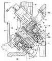
도 1은, 본 발명의 한 실시예에 다른 다관절 매니퓰레이터(20)의 일부를 나타낸 단면도,1 is a cross-sectional view showing a part of an articulated
도 2는, 다관절 매니퓰레이터(20)를 모식화해서 나타낸 측면도,2 is a side view schematically showing the articulated
도 3은, 다관절 매니퓰레이터(20)를 나타낸 단면도,3 is a cross-sectional view showing the articulated
도 4는, 다관절 매니퓰레이터(20)의 경사관절부 부근을 확대해서 나타낸 단면도,4 is an enlarged cross-sectional view showing the vicinity of the inclined joint portion of the articulated
도 5는, 다관절 매니퓰레이터(20)의 동축관절부 부근을 확대해서 나타낸 단면도로서, 전달기구가 보이도록 도 1의 방향에서 90°회전시킨 도면,FIG. 5 is an enlarged cross-sectional view of the vicinity of the coaxial joint of the articulated
도 6은, 본 실시예의 제1암체(30A) 및 제2암체(30B)의 변형상태를 모식적으로 나타낸 도면,FIG. 6 is a view schematically showing a deformation state of the
도 7은, 비교예의 제1암체(30A) 및 제2암체(30B)의 변형상태를 모식적으로 나타낸 도면,7 is a diagram schematically showing a deformation state of the
도 8은, 본 발명의 다른 실시예인 다관절 매니퓰레이터(100)의 일부를 나타낸 단면도,8 is a cross-sectional view showing a part of an articulated
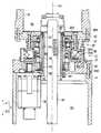
도 9는, 다관절 매니퓰레이터(100)를 나타낸 단면도,9 is a sectional view showing the articulated
도 10은, 도 8의 A-A선 절단면에서 본 다관절 매니퓰레이터(100)의 단면도,FIG. 10 is a cross-sectional view of the articulated
도 11은, 제1암체(30A)에 수용되는 2개의 구동모터(33, 34) 및 브레이크(133)를 설명하기 위한 사시도,11 is a perspective view for explaining the two
도 12는, 본 발명의 또 다른 실시예인 다관절 매니퓰레이터(300)의 일부를 나타낸 단면도,12 is a cross-sectional view showing a part of an articulated
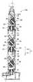
도 13은, 다관절 매니퓰레이터(300)를 모식화 해서 나타낸 측면도,13 is a side view schematically showing the articulated
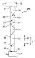
도 14는, 다관절 매니퓰레이터(300)를 나타낸 단면도이다.14 is a cross-sectional view illustrating the articulated
도 1은, 본 발명의 한 실시예에 따른 다관절 매니퓰레이터(20)의 일부를 나타낸 단면도이다. 본 발명의 한 실시예인 다관절 매니퓰레이터(20)는 복수의 암체(30)와, 이 암체(30)을 회전할 수 있게 연결하는 복수의 관절부(31, 32)를 갖고 있다. 각 암체(30)는 관절부(31, 32)에 의해 각각 연결되어 직렬로 뻗도록 되어있다.1 is a cross-sectional view showing a part of an articulated
각 관절부(31, 32)는, 동축관절부(31)와 경사관절부(32)를 갖고 있다. 동축관절부(31)는, 인접하는 2개의 암체(30)를 그 각 암체(30)의 축선(L)과 동축(同逐)의 동축회전축선(R1) 주위에다 회전할 수 있게 연결하게 된다. 또 경사관절부(32)는, 인접하는 2개의 암체(30) 중 한쪽을 각 암체(30)의 축선(L)에 대해 경사진 경사 회전축선(R2) 주위에 원추회전할 수 있게 연결한다.Each
한편, 본 발명에서 「원추회전」은, 경사 회전축선(R2)을 중심으로 해서, 2개의 암체(30)의 연결위치를 정점(頂点)으로 하는 가상 원추(假想圓錐)의 외주면을 따라 상대적으로 회전하는 것을 말한다. 또 본 발명에서 「회전」은 회전축선 주위에서 각변위하는 상태도 포함한다.On the other hand, in the present invention, the "conical rotation" is relatively along the outer circumferential surface of the virtual cone having the connection position of the two arm bodies 30 as the apex centered on the inclined rotation axis R2. It means to rotate. In addition, in this invention, "rotation" also includes the state displaced around a rotation axis.
이와 같은 동축관절부(31) 및 경사관절부(32)를 포함한 다관절 매니퓰레이터(20)는, 복수의 암체(30)를 각각 상대적으로 회전시켜 줌으로써, 뱀의 움직임과 같이 움직이도록 해서 3차원 위치결정을 할 수 있도록 한다. 예컨대 설비 등이 복잡해서 조립작업 경로가 복잡한 경우, 또 천정과 마루의 간격이 작아 저자세 작업이 필요한 경우 등에도, 본 발명에 따른 다관절 매니퓰레이터(20)는 그 선단에 연결되는 대상물을 적절히 목적하는 위치 및 자세로 배치할 수 있다.The articulated
도 2는 다관절 매니퓰레이터(20)를 모식화해서 나타낸 측면도이고, 도 3은 다관절 매니퓰레이터(20)를 나타낸 단면도이다. 예컨대 다관절 매니퓰레이터(20)는 직렬로 설치되는 6개의 암체(c1 ~ c6)와, 인접하는 2개의 암체를 회전할 수 있게 연결하는 복수의 관절부(31, 32)를 갖는다.2 is a side view schematically illustrating the articulated
다관절 매니퓰레이터(20)의 직렬방향 한쪽 단부에 설치되는 제1암체(c1)는 기대(21)에 연결되고, 직렬방향 다른쪽 단부에 설치되는 제6암체(c6)에는 핸드장치(hand unit;22)가 연결된다. 제1 ~ 제6암체(c1 ~ c6)는 그 각각의 축선이 동축으로 배치되어 일직선상으로 뻗는 상태로 변형될 수 있다. 각 관절부(31, 32)는 3개의 동축관절부(31)와 3개의 경사회전부(32)를 갖는다. 본 실시예의 경우, 암체(c1 ~ c6)의 직렬방향으로 동축관절부(31)와 경사관절부(32)가 교대로 배치되어 있다. 다관절 매니퓰레이터(20)는 인접하는 암체를 상대적으로 회전시켜줌으로써, 선단부의 암체(c6)를 목표로 하는 위치 및 자세로 배치할 수 있게 된다.The first arm c1 installed at one end in the serial direction of the articulated
다관절 매니퓰레이터(20)의 선단부에는, 각종 핸드장치, 이른바 엔드 이펙터(end effector)가 연결되어 있다. 다관절 매니퓰레이터(20)는 핸드장치를 목표위치에다 배치하게 된다. 예컨대 다관절 매니퓰레이터(20)는 자동차 밖에서 자동차 내로 핸드장치(22)를 배치하게 된다. 또, 예컨대 다관절 매니퓰레이터(20)는 마루의 면과 천정 사이의 공간에 핸드장치(22)를 배치한다. 목표위치에 배치된 핸드장치(22)는 예컨대 핸들링, 실링, 도장, 스폿용접, 아크용접 등을 실행한다.Various hand devices, so-called end effectors, are connected to the distal end of the articulated
도 1에 도시된 것과 같이, 각 암체(30)는 그 축선(L) 주위를 일주하는 주벽부(周壁部;41)와, 축선방향(Z) 양단부에 설치되고서 주벽부(41)에 연결되어 주벽부(41)를 막아주는 단벽부(端壁部;42)를 갖는다. 각 암체(30)는, 주벽부(41)와 각 단벽부(42)에 의해 각 암체(30) 내부에 암 내부공간(40)이 형성되어 있다.As shown in FIG. 1, each arm 30 is connected to the
또, 인접하는 2개의 암체(30)는 베어링(36)에 의해 회전할 수 있게 연결된다. 이 베어링(36)은 내륜(內輪)측 링과 외륜측 링이 상대적으로 회전할 수 있게 설치되어 있다. 베어링(36)의 내륜측 링이 한쪽 암체에 고정되고, 베어링(36)의 외륜측 링은 다른쪽 암체에 고정된다. 이 베어링(36)은, 예컨대 링 모양의 크로스 롤러 베어링에 의해 실현되게 된다. 크로스 롤러 베어링(cross roller bearing)에 의해 실현됨으로써, 단체(單體) 베어링으로부터 레디얼 하중 및 액시얼 하중을 받게 되더라도 2개의 암체를 회전할 수 있게 지지할 수가 있다.In addition, two adjacent arm bodies 30 are rotatably connected by a
동축관절부(31)에서는, 연결되는 2개의 암체(30)의 축선과 베어링(36)의 회전축선이 일치하게 된다. 동축관절부(31)가 연결하는 2개의 암체(30)는 베어링(36)에 고정되는 동축연결면(37)을 각각 갖는다. 각 동축연결면(37)이 각 암체(30)의 단벽부(42)에 설치되고서 암체(30)의 축선(L)에 수직으로 된다.In the coaxial
경사관절부(32)에서는, 연결되는 2개의 암체(30)의 축선과 베어링(36)의 회전축이 경사져 있게 된다. 경사관절부(32)가 연결하는 2개의 암체(30)는 베어링(36)에 고정되는 경사연결면(38)을 각각 갖는다. 각 경사연결면(38)은 각 암체(30)의 단벽부(42)에 설치되고서, 암체(30)의 축선(L)에 대해 경사져 있게 된다. 또 각 경사연결면(38)은 상호평행하게 되어 있다. 본 실시예에서는, 경사연결면(38)과 암체의 축선이 45°의 경사각을 이루도록 되어 있다.In the inclined
이와 같이 베어링(36)에 의해 연결되는 2개의 암체(30)는 베어링(36)의 회전축선 주위를 회전하게 된다. 따라서, 베어링(36)의 회전축선이 각 암체(30)의 회전축선(R1, R2)으로 된다. 또 각 단벽부(42)에는 암체(30)의 회전축선(R1, R2)을 따라 단벽부(42)를 관통하는 관통구멍(39)이 형성되어 있다. 이 관통구멍(39)은 회전축선(R1, R2)과 동축으로 뻗어 암 내부공간(40)과 연통하게 된다.In this way, the two arm bodies 30 connected by the bearing 36 rotate around the rotation axis of the
다관절 매니퓰레이터(20)는 전기배선 또는 호스 등으로 이루어진 삭조(索條;35)를 구비하고 있다. 이 삭조(35)는 암체(30)의 내부를 축선방향(Z)으로 삽통하게 된다. 또 삭조(35)는 가요(可撓)성을 가져, 암체(30)가 회전을 하게 되면 다관절 매니퓰레이터(20)와 함께 변형되게 된다.The articulated
또 다관절 매니퓰레이터(20)는, 인접하는 2개의 각 암체(30)를 상대적으로 회전구동하는 구동수단을 갖도록 되어 있다. 이 구동수단은 구동모터(33, 34)를 포함해서 실현되게 된다. 각 암체(30)는, 2개의 구동모터(33, 34)가 내장되는 제1암체(30A)와, 구동모터(33, 34)가 내장되지 않은 제2암체(30B)를 갖는다. 여기서, 제 1암체(30A)와 제2암체(30B)라 함은 구동모터(33, 34)를 포함하고 있는지 여부에 따라 식별하기 위한 호칭으로서, 다관절 매니퓰레이터(20)를 구성하는 제1 ~ 제6암체(c1 ~ c6) 중 제1암체(c1)와 제2암체(c2)의 호칭과는 구별되어야 할 것이다.The articulated
제1암체(30A)의 한쪽 편에는 제2암체(30B)가 연결된다. 본 실시예에서는, 제1암체(30A)와 제2암체(30B)가 교대로 배치되어 있다.The
제1암체(30A)에 내장되는 2개의 구동모터(33, 34) 중 한쪽 구동모터(33)는, 제1암체(30A)와 그 축선방향 한쪽(Z1)에 연결되는 제2암체(30B)를 상대회전시키기 위해 설치된 것이다. 또 제1암체(30A)에 내장되는 2개의 구동모터(33, 34) 중 다른 쪽 구동모터(34)는, 제1암체(30A)와 그 축선방향 다른 한쪽(Z2)에 연결되는 제2암체(30B)를 상대회전하기 위해 설치된다. 한쪽 구동모터(33)와 다른쪽 구동모터(34)는, 내장되는 제1암체(30A)의 축선방향(Z1, Z2)에 관해 제1암체(30A)의 암 내부공간(40) 중 적어도 부분적으로 공통의 중첩영역(135)에 배치되고서, 축선방향에 수직인 방향으로 배열된다.One of the two driving
또 다관절 매니퓰레이터(20)는, 암체를 구동하는 구동원으로 되는 구동모터(33, 34) 외에, 구동모터(33, 34)로부터 전달되는 회전구동력을 감속하는 감속기구(44)와, 복수의 평기어를 구비할 수 있는 기어열로 이루어져, 구동모터(33, 34)로부터의 회전구동력을 감속기구(44)로 전달하게 되는 전달기구(45)를 갖고 있다. 감속기구(44)는, 입력되는 회전속도에 대해 출력되는 회전속도가 현저히 낮은, 높은 감속비로 된 것이 쓰이게 된다. 본 실시예에서는, 높은 감속비를 실현하는 감속기구로서, 파동기어기구인 이른바 하모닉 드라이브(등록상표)가 쓰이게 된다. 또 높 은 감속비의 감속기구로는 하모닉 드라이브 이외의 기구라도 좋은바, 유성기어 감속기구나 특수 톱날형 감속기구도 적용될 수 있다.In addition to the
도 4는 다관절 매니퓰레이터(20)의 경사관절부 부근을 확대해서 나타낸 단면도이다. 감속기구(44)는 입력축(48)과 출력축(49) 및 고정축(50)을 갖는다. 입력축(48) 및 출력축(49)은 미리 정해진 회전축선 주위를 회전하게 된다. 감속기구(44)는 회전구동하게 되는 입력축(48)의 회전속도에 비례해서 고정축(50)에 대해 출력축(49)을 감속시켜 회전구동하게 된다. 환언하면, 고정축(50)과 출력축(49)을 상대적으로 회전시킨다. 본 실시예에서는, 앞에서 설명한 바와 같이, 감속기구(44)로 링 모양의 파동기어기구(harmonic reduction gear)가 쓰여져, 입력축(48) 및 출력축(49)의 회전축선이 베어링(36)의 회전축선(R1)과 동축으로 설치되어 있다.4 is an enlarged cross-sectional view showing the vicinity of the inclined joint portion of the articulated
경사관절부(32)에 임하는 제1암체(30A)의 단벽부(42)에는, 볼트 부재에 의해 구동모터(33) 및 감속기구(44)의 출력축(49)이 착탈될 수 있게 고정된다. 또 경사관절부(32)에 임하는 제2암체(30B)의 단벽부(42)에는, 볼트 부재에 의해 감속기구(44)의 고정축(50)이 착탈될 수 있게 고정된다.The
구동모터(33)는 그 회전축(43)이 회전할 수 있게 설치되어, 회전축(43)과 일체로 구동측 평기어(46)가 고정된다. 구동측 평기어(46)는 종동측 평기어(47)와 서로 맞물리게 된다. 종동측 평기어(47)는 회전할 수 있게 설치되어, 볼트 부재에 의해 감속기구(44)의 입력축(48)에 착탈될 수 있게 고정된다. 감속기구(44)의 입력축(48)이 감속기구(44)의 내주에 설치되어 링 모양을 이루도록 되어 있다. 또, 종동측 기어(47)도 링 모양으로 형성되어 있다. 종동측 기어(47)는, 감속기구(44)의 내 부공간과 외부공간이 연통하도록 감속기구(44)의 입력축(48)에 고정된다. 또 종동측 평기어(47) 및 감속기구(44)의 입력축(48)은, 베어링(36)의 회전축선과 동축으로 배치되어, 베어링(36)의 회전축선 주위를 회전할 수 있게 설치된다.The
구동측 기어(46)는 베어링(36)의 회전축선, 즉 2개의 암체(30A, 30B)의 회전축선(R2)과 평행한 축선을 갖도록 되어 있다. 이에 따라 구동모터(33)의 회전축(43)은 구동측 평기어(46) 및 종동측 평기어(47)가 서로 맞물린 상태에서, 암체(30A, 30B)의 회전축선(R2)과 평행하도록 배치되어 있다.The
또 감속기구(44)의 출력축(49)은 제1암체(30A)에 고정되고, 감속기구(44)의 고정축(50)은 제2암체(30B)에 고정된다. 이에 따라 감속기구(44)의 입력축(48)으로부터 회전구동력이 주어지면, 고정축(50)에 대해 출력축(49)이 감속되어 회전하게 되어, 제1암체 및 제2암체(30A, 30B)가 상대적으로 회전하게 된다. 또, 구동측 기어(46)의 이빨 수는 종동측 기어(47)의 이빨 수보다 적어, 감속비를 더 크게 할 수가 있다.The
도 5는 다관절 매니퓰레이터(20)의 동축관절부 부근을 확대해서 나타낸 단면도이다. 단, 전달기구가 보여지도록 도 1을 90°회전시킨 방향의 도면으로 되어 있다. 동축관절부(31)도 경사관절부(32)와 마찬가지로 감속기구(44) 및 전달기구(45)가 설치되어 있다. 구체적으로는, 동축관절부(31)에 임하는 제1암체(30A)의 단벽부(42)에는, 볼트 부재에 의해 구동모터(34) 및 감속기구(44)의 출력축(49)이 착탈될 수 있게 고정되는 한편, 동축관절부(31)에 임하는 제2암체(30B)의 단벽부(42)에는, 볼트 부재에 의해 감속기구(44)의 고정축(50)이 착탈될 수 있게 고정되어 있다.5 is an enlarged cross-sectional view of the vicinity of the coaxial joint of the articulated
구동모터(34)는 그 회전축(43)이 회전할 수 있게 설치되고서, 회전축(43)과 일체로 구동측 평기어(46)가 고정되어 있다. 이 구동측 평기어(46)는 종동측 평기어(47)와 서로 맞물려지게 된다. 또, 이 종동측 평기어(47)는 회전할 수 있게 설치되어, 볼트 부재에 의해 감속기구(44)의 입력축(48)에 착탈될 수 있게 고정되어 있다. 그리고, 상기 종동측 평기어(47) 및 감속기구(44)의 입력축(48)은 베어링(36)의 회전축선과 동축으로 배치되어, 베어링(36)의 회전축선 주위를 회전할 수 있게 설치된다.The
구동측 기어(46)는 베어링(36)의 회전축선, 즉 2개의 암체(30A, 30B)의 회전축선(R1)에 평행한 축선을 갖도록 되어 있다. 그에 따라, 구동모터(34)의 회전축(43)은 구동측 평기어(46) 및 종동측 평기어(47)가 서로 맞물린 상태로 암체(30A, 30B)의 회전축선(R1)과 평행하도록 배치될 수 있게 된다. 상기 구동측 기어(46)의 이빨 수는 종동측 기어(47)의 이빨 수보다 적어 감속비를 더 크게 할 수가 있다.The
또, 링 모양으로 형성된 감속기구(44)의 중공공간(54)은, 연결되는 2개의 암체(30A, 30B) 중 한쪽 암체(30A)의 단벽부(42)의 관통구멍(39)과 다른쪽 암체(30B)의 단벽부(42)의 관통구멍(39)을 연통하게 된다. 삭조(35)는 한쪽 단벽부(42)의 관통구멍(39)에서부터 감속기구(44)의 중공공간(54)을 삽통해서 다른쪽 단벽부(42)의 관통구멍(39)으로 뻗게 됨으로써 복수의 암체에 걸쳐 삽통될 수 있게 된다.Further, the
또, 다관절 매니퓰레이터(20)에는, 인접하는 2개의 암체(30A, 30B) 중 한쪽 암체(30A)의 단벽부(42)의 관통구멍(39)과, 감속기구(44)의 중공공간(54) 및 다른쪽 암체(30B)의 단벽부(42)의 관통구멍(39)을 삽통하는 통 모양의 삭조보호부재 (55)가 설치되어 있다. 각 삭조보호부재(55)는 인접하는 2개의 암체(30A, 30B)의 사이에 설치되고서, 인접하는 2개의 암체(30A, 30B)의 회전축선(R1, R2)과 동축으로 배치되도록 되어 있다.In addition, the articulated
삭조보호부재(55)는 어느 한쪽 암체의 한쪽 단벽부(42)에 고정되고서, 다른 쪽 암체의 단벽부(42)까지 뻗도록 되어 있다. 또, 삭조보호부재(55)는 고정이 되는 한쪽 암체(30)와 함께 회전을 하게 된다. 본 실시예에서는, 삭조보호부재(55)가 제1암체(30A)의 단벽부(42)에 고정되도록 되어 있다. 또 삭조보호부재(55)의 외주면과 제1암체(30A)의 단벽부(42)의 관통구멍(39)에 임하는 내주면(56)과는 개스킷 또는 0링 등의 밀봉부재에 의해 그 간극이 막혀지도록 되어 있다. 또 삭조보호부재(55)의 외주면과 제2암체(30B)의 단벽부(42)의 관통구멍(39)에 임하는 내주면과는, 오일 실 등의 밀봉부재에 의해, 그 간극이 막혀지도록 되어 있다. 즉, 제2암체(30B)의 단벽부(42)와 삭조보호부재(55)의 상대회전을 허용은 하지만, 삭조보호부재(55)의 외주면(57)과 제2암체(30B)의 단벽부(42)의 내주면의 간극이 막혀지게 된다.The cutting
이에 따라 감속기구(44) 및 전달기구(45)가 설치되는 영역과 삭조보호부재(55) 내의 공간이 밀봉되게 구분되게 된다. 감속기구(44) 및 전달기구(45)에는, 원활한 구동력의 전달 및 구동력의 감속을 실행하기 위해 윤활유 또는 오일 등의 윤활제가 도포된다. 밀봉부재에 의해 삭조보호부재(55)와 각 단벽부의 내주면(56, 57)과의 간극이 막혀지게 되므로, 감속기구(44) 및 전달기구(45)에 도포된 윤활제가 누설되어 삭조보호부재(55) 및 암 내부공간(40)에 침입하는 것을 방지할 수가 있게 된다.Accordingly, the area in which the
또, 삭조(35)가 삭조보호부재(55)를 삽통해서 뻗게 됨으로써, 감속기구(44) 및 전달기구(45)에 삭조(35)가 접촉하는 것을 방지할 수 있게 된다. 2개의 암체(30A, 30B)를 상대회전함에 있어, 감속기구(44) 및 전달기구(45)가 가동하더라도, 삭조(35)가 감속기구(44) 및 전달기구(45)에 접촉하지 않기 때문에, 삭조(35)의 파손을 막을 수 있게 된다. 또 삭조보호부재(55)는 삭조(35)에 임하는 부분이 삭조(35)에 대해 마찰저항이 적은 재료로 만들어지는 것이 바람직하다.In addition, since the cutting
이상과 같이 본 발명의 1실시예에 의하면, 제1암체 및 제2암체(30A, 30B)에 암 내부공간(40)이 형성되게 된다. 또, 삭조보호부재(55)가 인접한 2개의 암체(30A, 30B) 사이를 연통하게 된다. 이에 따라 삭조(35)를 다관절 매니퓰레이터(20)에 내장시켜 각 암체의 직렬방향으로 뻗게 할 수가 있다.As described above, according to the exemplary embodiment of the present invention, the arm
삭조(35)는 다관절 매니퓰레이터(20)의 외부표면을 따르지 않는다. 이에 의해 삭조(35)가 다관절 매니퓰레이터(20) 주변의 장애물에 접촉하는 것이 방지될 수 있다. 따라서, 작업공간이 좁은 경우 또는 장애물이 다수 배치된 경우라 하더라도 삭조(35)의 파손을 막을 수 있게 된다.The cutting
삭조(35)는, 예컨대 구동모터(33, 34)를 회전시키기 위한 전력이나 구동모터(33, 34)의 회전지령을 나타낸 전기신호 등을 공급하는 전기배선이어도 좋고, 다관절 매니퓰레이터(20)의 선단부에 연결되는 핸드장치의 동력, 핸드장치가 소비하는 소비물 등을 공급하는 호스이어도 좋다. 예컨대 핸드장치가 접착장치인 경우에는, 접착제를 삭조(35)에 의해 공급되도록 하여도 좋다. 또 핸드장치가 도포장치인 경 우에는, 삭조(35)에 의해 도료가 공급되도록 하여도 좋다.The cutting
또 제1암체(30A)에 2개의 구동모터(33, 34)를 배치해서, 각 구동모터(33, 34)를 축선방향(Z)에 수직인 방향으로 배열함으로써, 2개의 구동모터(33, 34)를 내장하기 위해 필요한 제1암체(30A)의 축선방향 치수를 소형화할 수가 있다. 그리고, 제2암체(30B)에는 구동모터(33, 34)를 배치할 필요가 없기 때문에, 구동모터(33, 34)의 크기에 관계없이 제2암체(30B)의 형상을 소형화할 수가 있다. 그에 따라, 제1암체 및 제2암체(30A, 30B)를 소형화할 수 있기 때문에, 전체적으로 다관절 매니퓰레이터(20)를 소형화할 수 있게 된다. 다관절 매니퓰레이터(20)를 소형화함으로써, 좁은 작업공간이라 하더라도 다관절 매니퓰레이터(20)의 선단부를 목표하는 위치 및 자세로 유지되게 할 수가 있다.In addition, by arranging two
그리고, 다관절 매니퓰레이터(20)는 고감속비의 감속기구(44)를 가져, 이 감속기구(44)를 이용해서 구동모터(33, 34)로부터의 구동회전력을, 연결되는 2개 암체의 어느 한쪽에다 전하게 된다. 이에 따라 소형의 구동모터(33, 34)를 이용하는 경우라 하더라도, 암체를 회전시키는데 필요한 토크를 얻을 수 있게 된다. 바꿔 말해, 소형의 구동모터(33, 34)를 이용할 수가 있어, 구동모터를 내장하는 제1암체(30A)의 축선방향 치수를 한층 더 소형화할 수 있게 된다. 또 구동모터(33, 34)의 회전축(43)의 회전이 제어되어, 다관절 매니퓰레이터(20)의 위치결정이 이루어지는 경우, 고감속비의 감속기구(44)를 개입시킴으로써 위치결정 정밀도를 향상시킬 수 있게 된다.The articulated
또, 삭조(35)는 삭조보호부재(55)를 통과해서, 연결되는 2개의 암체 사이로 뻗게 된다. 삭조(35)는 삭조보호부재(55)에 의해 감속기구(44) 및 전달기구(45)에 접촉하지 않게 된다. 그에 따라 감속기구(44) 및 전달기구(45)가 암체를 회전하기 위해 회전변위하게 되어도, 삭조(35)가 회전변위하는 감속기구(44) 및 전달기구(45)에 접촉되는 것이 방지될 수 있게 된다.In addition, the cutting
그리고, 감속기구(44) 및 전달기구(45)가 배치되는 영역과 삭조보호부재(55)의 중공공간이 밀하게 구분되어 있기 때문에, 감속기구(44) 및 전달기구(45)에 윤활제를 도포하더라도, 윤활제가 누설되어 삭조보호부재(55)의 중공공간 및 암체 내부공간(40)으로 윤활제가 침입하는 것이 방지될 수가 있다. 동시에 윤활부족에 의한 감속기구(44) 및 전달기구(45)의 손상도 방지될 수 있게 된다. 또, 이와는 반대로, 삭조 내를 흐르는 물질인 예컨대 도료 및 접착제 등이 감속기구(44) 및 전달기구(45)에 침입하지 못하게 된다. 또 감속기구(44) 및 전달기구(45)의 열이 삭조(35)로 전해지기 어렵게 된다.Since the hollow spaces of the area where the
또, 평기어(46, 47)를 써서 전달기구(45)를 달성함으로써, 단순한 구성의 전달기구(45)를 실현할 수 있게 된다. 평기어(46, 47)를 이용함으로써, 벨트에 의한 전달에 비해 구동모터(33, 34)로부터의 회전구동력을 확실히 전달할 수 있게 되어, 허용될 수 있는 동력도 커지게 된다. 그에 따라 전달기구(45)의 신뢰성을 향상시킬 수가 있어, 고정밀도의 위치결정을 실행할 수 있게 된다. 또 구동측 기어(46) 보다도 종동측 기어(47)의 이빨 수를 많게 함으로써, 전달기구(45)에서도 감속기구를 달성할 수가 있기 때문에 구동모터(33, 34)의 회전속도를 한층 더 감속시킬 수 있게 된다.Moreover, by using the spur gears 46 and 47 to achieve the
또, 내치 베벨기어 전달과 달리 전달기구(45)의 각 기어(46, 47)는, 구동모터(33, 34)의 회전축(43)의 회전축선과 감속기구(44)의 입력축(48)의 회전축선을 나란해지도록 할 수가 있다. 그에 따라 구동모터(33, 34)를 지지하는 지지부 및 감속기구(44)를 지지하는 지지부의 가공 및 조립이 쉬워질 수 있게 된다.In addition, unlike the internal bevel gear transmission, the
여기서, 벨트전달에 의해서도 구동모터(33)와 감속기구(44)의 회전축을 평행하도록 할 수 있으나, 한편으로는 벨트의 부착 및 장력을 조정하는 기구를 각각 설치할 필요가 있어, 구조가 복잡해지게 된다. 또 그 기구를 형성하기 위해 암체의 형상이 대형화된다. 또, 벨트의 휨용량이 작기 때문에 고감속비를 얻을 수 없는 경우가 있다.Here, the rotational axis of the
본 실시예에서는, 전달기구(45)에 평기어를 이용함으로써 전달기구(45)로서 벨트를 이용하는 경우에 비해 제1암체(30A)의 구조를 간략화할 수가 있어, 제1암체(30A)를 더 소형화할 수가 있다.In this embodiment, by using the spur gear for the
또, 종동측 기어(47)에 서로 맞물리는 위치에 있으면, 구동측 기어(46)의 배치위치를 쉽게 이동시킬 수가 있다. 그에 따라, 삭조(35)가 제1암체 내를 삽통하는 공간을 충분히 확보할 수 있음과 더불어, 제1암체(30A)가 소형이 되도록 한 배치위치에 각 구동모터(33, 34)를 쉽게 배치할 수 있게 된다.Moreover, if it is in the position which meshes with the driven
또 본 실시예에서는, 경사관절부(32)에 의해 연결되는 2개의 암체의 회전축선(R2)이 각 암체의 축선에 대해 모두 45°만큼 경사져 있게 된다. 이에 따라 다관절 매니퓰레이터(20)를 제조하기 위해 필요한 부품의 종류가 줄여질 수가 있다.In addition, in this embodiment, the rotation axis R2 of the two arm bodies connected by the inclined
도 6은 본 실시예의 제1암체(30A) 및 제2암체(30B)의 변형상태를 모식적으로 나타낸 도면이다. 도 7은 비교예의 제1암체(30A) 및 제2암체(30B)의 변형상태를 모식적으로 나타낸 도면이다. 암의 길이(L5)를 가급적 짧게 한 경우에는, 구동모터(33, 34)가 포함된 제1암체(30A)의 축선방향 길이(L4)보다 제2암(30B)의 축선방향 길이(L3)가 짧게 형성된다.FIG. 6 is a diagram schematically showing a deformation state of the
이 경우, 경사관절부(32)에 의해 연결되는 각 암체(30A, 30B) 중 기단부측인 기대(21)측에 제2암체(30B)를 배치해서, 경사관절부(32)의 유단부(遊端部)측인 핸드장치측에 제1암체(30A)를 배치하는 것이 바람직하다. 즉, 기대측을 구동측의 암체로 하고, 핸드장치측을 종동측의 암체로 하면, 종동측의 암체에 구동모터(33, 34)가 고정되게 된다. 제1암체(30A)의 2개의 구동모터(33, 34) 중 한쪽 구동모터(33)는, 미리 정한 위치에 배치되는 제2암체(30B)에 대해 제1암체(30A)를 회전구동시키게 된다. 본 실시예에서는, 도 6에 도시된 것과 같이, 제1암체(30A)가 그 축선방향 길이(L4)를 모선(母線)으로 해서, 경사관절부(32)의 회전축선(R2) 주위를 회전하게 된다. 이에 대해 비교예에서는, 도 7에 도시된 것과 같이, 제2암체(30B)가 그 축선방향 길이(L3)를 모선으로 해서, 경사관절부(32)의 회전축선(R2) 주위를 회전하게 된다. 제1암체(30A)의 축선방향 길이(L4)는 제2암체(30B)의 축선방향 길이(L3)보다 길기 때문에, 본 실시예가 비교예에 비해 회전하는 암체의 회전반경을 크게 할 수가 있어, 다관절 매니퓰레이터의 가동범위를 넓게 할 수가 있다. 따라서, 다관절 매니퓰레이터의 암 길이를 가급적 작게 한 경우라 하여도, 비교예에 비해 암체의 가동범위를 넓게 할 수가 있다. 환언하면, 다관절 매니퓰레이터의 암 길이(L5)가 미리 정해져 있는 경우, 제2암체(30B)의 축선방향 길이(L3)를 작게 하여 제 1암체(30A)를 각변위시켜 줌으로써 가동범위를 넓어지게 할 수 있게 된다.In this case, the
그리고, 본 실시예에서는, 다관절 매니퓰레이터가 기대(21)로부터 위쪽을 향해 뻗고서, 기대측에 배치되는 제2암체(30B)가 아래쪽에 위치하고, 핸드장치측에 배치되는 제1암체(30A)가 위쪽에 위치하는 경우가 많다. 또, 제1암체(30A)는 경사관절부(32)보다 위쪽에 배치되는 일이 많다. 그에 따라 구동모터(33)는 경사관절부(32)보다 위쪽에 배치되어, 구동모터(33)에 경사관절부(32)의 감속기구(44) 등으로부터 윤활제가 침입하는 것을 방지할 수 있게 된다.In the present embodiment, the articulated manipulator extends upward from the
또, 감속기구(44)로서 하모닉 드라이브를 이용한 경우에는, 뒤에 설명되듯이, 윤활제가 필요한 하모닉 드라이브의 윤활영역이 제2암체(30B)측에 설치되도록 되어 있다. 제2암체(30B)가 경사관절부(32)보다 아래쪽에 위치함으로써, 윤활제가 하모닉 드라이브의 윤활영역으로 이동하기가 쉬워 하모닉 드라이브가 윤활부족으로 되는 것을 방지할 수가 있다.In addition, when a harmonic drive is used as the
하모닉 드라이브에 대해 설명하자면, 이는 도 4 및 도 5에 도시된 것과 같이, 그 입력축(48)이, 타원형 캠의 외주에 두께가 얇은 볼 베어링(200)이 끼워져 전체가 타원형을 이루도록 된 부품이다. 이 베어링(200)의 내륜(inner ring;202)은 캠(201)을 매개로 종동측 평기어(47)에 고정되어 있고, 베어링(200)의 외륜(203)은 볼(204)을 매개로 탄성변형할 수 있도록 되어 있다. 또, 고정축(50)은 강체(剛體)로 된 링 모양의 부품이다. 고정축(50)에는 그 내주부를 일주하는 내치(內齒; 205)가 형성되어 있는바, 이 내치(205)는 출력축(49)의 외주부에 형성되는 외치(206)가 맞물리도록 형성되고서, 외치(205)의 이빨 수보다 2개가 많게 형성되어 있다. 출력 축(49)은 탄발성 및 가요성을 가진 원통형상 부분(207)과, 이 원통형상 부분(207)의 일 단부에 배열된 고정부분(208)을 가진 금속제 부품이다. 원통형상 부분(207)에는 그 외주부에 고정축(5O)의 내치(205)와 맞물리는 외치(206)가 형성되어 있다. 고정부분(208)은 제1암체(30A)와 일체로 고정되게 된다.Referring to the harmonic drive, as shown in Figs. 4 and 5, the
원통형상 부분(207)은 베어링(200)의 외륜(203)에 끼워져 타원형으로 휘어지도록 되어 있다. 원통형상 부분(207)의 외치(203)는 타원으로 휘어진 외주부 중 장축(長軸)부분에서 고정축(50)의 내치(205)와 맞물리게 된다. 또 타원형상 부분(207)의 외치(203)는, 타원으로 휘어진 외주부 중 단축(短軸) 부분에서 고정축(50)의 내치(205)와 맞물려지지 않게 된다. 입력축(48)을 회전시키면, 입력축(48)과 함께 원통형상 부분(207)이 탄성변형되어, 내치(205)와 외치(206)가 맞물리는 위치가 순차로 이동하게 된다. 입력축(48)이 1회전을 하면, 출력축(49)은 고정축(50)의 내치(205) 보다 출력축(50)의 외치(206)의 이빨 수가 2개가 적기 때문에, 이빨 수의 차이 2개 분만큼 입력축(48)의 회전방향과 반대방향으로 이동하게 된다. 이 반대방향으로의 이동을 출력으로서 취출하여 고감속비 기구를 실현할 수 있게 된다.The
하모닉 드라이브에서, 내치(205)와 외치(206)의 사이 및 베어링의 외륜(203)과 원통형상 부분(207) 사이가 고속으로 회전접촉하고 있어서 윤활제를 충분히 보급할 필요가 있다. 따라서 내치(205)와 외치(206) 사이 및 베어링의 외륜(203)과 원통형상 부분(207) 사이가 윤활이 필요한 윤활영역으로 된다.In the harmonic drive, between the
따라서, 하모닉 드라이브에서의 윤활영역은 고정축(50)측, 즉 제2암체(30B) 측에 마련되어 있다. 앞에서 설명한 바와 같이 제2암체(30B)이 아래쪽에 배치되면, 하모닉 드라이브 중 윤활영역이 아래쪽에 배치되게 된다. 따라서, 윤활제가 윤활영역으로 이동하기가 쉬워, 하모닉 드라이브가 윤활부족에 빠지는 것이 방지될 수가 있다.Accordingly, the lubrication area in the harmonic drive is provided on the fixed
도 8은 본 발명의 다른 실시예에 따른 다관절 매니퓰레이터(100)의 일부를 나타낸 단면도이고, 도 9는 다관절 매니퓰레이터(100)를 나타낸 단면도이다. 도 10은 도 8의 A-A선 절단면에서 본 다관절 매니퓰레이터(100)의 단면도이고, 도 11은 제1암체(30A)에 수용되는 2개의 구동모터(33, 34) 및 브레이크(133)를 설명하기 위한 사시도이다. 다관절 매니퓰레이터(100)는, 그 구동수단으로서 구동원인 구동모터(33)와 제동부인 브레이크(133)가 별개로 설치되어 있다. 구동모터(33)는 그 회전축이 구동측 기어에 고정되게 된다. 이 구동측 기어가 종동측 기어(47)에 서로 맞물려짐으로써 종동측 기어(47)를 회전구동하게 된다. 브레이크(133)는 그 회전축이 제동측 기어에 고정된다. 이 제동측 기어가 종동측 기어(47)에 서로 맞물려짐으로서 종동측 기어(47)를 제동하게 된다. 이와 같이 종동측 기어(47)는 구동측 기어(46)와 제동측 기어의 2개의 기어에 서로 맞물려짐으로써 구동 및 제동이 이루어질 수 있게 된다. 구동모터(33)와 브레이크(133)는 제1암체(30A)의 축선방향(Z)에 관해서는 적어도 부분적으로 공통영역에 배치되어 있다. 기타의 구성에 대해서는 도 1에 도시된 다관절 매니퓰레이터(20)와 마찬가지로 구성되어 있어, 그에 대한 설명을 생략하기로 하고서 동일한 참조부호를 붙이기로 한다.8 is a cross-sectional view showing a part of the articulated
통상, 구동모터(33)와 브레이크(133)는 일체로 설치되고서, 이들 구동모터(33)와 브레이크(133)가 동축으로 배열되어 있다. 이 경우, 브레이크(133)를 포함 한 구동모터(33)는, 브레이크(133)를 포함하는 것만큼 그 축선방향 치수가 커지게 된다. 이와 같은 경우에는, 제1암체(30A)가 구동모터(33)를 수용하기 위해 필요한 공간보다 브레이크(133)만큼 더 큰 공간이 필요하게 된다. 환언하면, 제1암체의 축선방향 치수 및 외경 치수가 브레이크(133) 분만큼 커지게 된다.Usually, the
본 발명에서는, 구동모터(33)와 브레이크(133)를 별개로 설치하고서, 제1암체(30A)의 축선방향으로 구동모터(33)와 브레이크(133)를 배열하도록 하였다. 이에 따라, 브레이크(133) 분을 고려하지 않고 제1암체(30A)의 축선방향 치수 및 외경 치수를 작게 할 수가 있다. 구동모터(33) 및 브레이크(133)는, 삭조(35)가 제1암체(30A)를 삽통하게 되는 공간을 확보하면서도, 제1암체(30A)의 축선방향 치수 및 외경 치수가 작아질 수 있도록 배치되어 있다.In the present invention, the
제1암체(30A)는, 축선방향 한쪽(Z1)의 구동모터(33)와 브레이크(133)가 분리되는 한쪽의 구동수단과, 축선방향 다른 한쪽(Z2)의 구동모터(34)와 브레이크가 일체로 된 다른쪽 구동수단을 내장하게 된다.The
또, 앞에서 설명한 바와 같이, 최적 위치(P1) 근방에 축선방향 한쪽(Z1)의 구동모터(33)가 고정됨으로써, 축선방향 한쪽(Z1)의 구동모터(33)의 축선방향 치수가 큰 경우라 하더라도, 주벽부(41) 및 단벽부(42)의 내면(52, 53)에 접촉을 하지 않아, 축선방향 한쪽(Z1)의 구동모터(33)를 제1암체(30A)에 내장할 수가 있게 되어, 제1암체(30A)를 소형화할 수 있게 된다. 환언하면, 축선방향 한쪽(Z1)의 구동모터(33)를 제1암체(30A)에 내장함으로써 제1암체(30A)의 축선방향 치수를 작게 할 수가 있다.As described above, when the driving
또, 축선방향 다른 한쪽(Z2)의 구동모터(34)는 삭조(35)가 삽통하는 공간을 확보함으로써, 축선방향 한쪽(Z1)의 구동모터(33), 브레이크(133), 단벽부(42) 및, 주벽부(41)에 접촉하지 않는 한 임의의 위치에 배치할 수가 있다.In addition, the
이상과 같은 본 발명의 다른 형태의 다관절 매니퓰레이터(100)에서는, 도 1에 도시된 다관절 매니퓰레이터(20)와 마찬가지 효과를 얻을 수가 있다. 그리고 구동모터(33)와 브레이크(133)를 분할해서 배치함으로써, 제1암체(30A)를 축선방향으로 더 소형화할 수가 있다.In the articulated
다음에는, 도 12와 도 13 및 도 14를 참조해서, 본 발명의 또 다른 실시예에 따른 다관절 매니퓰레이터(300)에 대해 설명한다. 다관절 매니퓰레이터(300)에서의 복수의 암체(30)는, 일단이 경사지고 타단이 수평암체인 외에, 상단과 하단이 같은 방향 또는 반대방향으로 함께 경사진 암체로 이루어져 있고, 이에 대응하여 다관절 매니퓰레이터(300)는, 복수의 암체를 연결하는 동축관절부(31)와 경사회전부(32)의 배열 및 개수가 도 1에 도시된 다관절 매니퓰레이터(20)와는 다르게 되어 있다. 이러한 것을 제외하면, 다관절 매니퓰레이터(300)는 다관절 매니퓰레이터(20)와 거의 마찬가지 구성으로 되어 있다. 따라서, 다관절 매니퓰레이터(20)와 마찬가지 구성에 대해서는 설명을 생략하고 같은 참조부호를 붙이기로 한다.Next, the articulated
도 12는 본 발명의 한 실시예인 다관절 매니퓰레이터(300)의 일부를 나타낸 단면도이다. 도 13은 다관절 매니퓰레이터(300)를 모식화해서 나타낸 측면도이고, 도 14는 다관절 매니퓰레이터(300)를 나타낸 단면도이다. 다관절 매니퓰레이터(300)는, 직렬로 설치되는 6개의 암체(c1 ~ c6)와, 근접하는 2개의 암체를 회전할 수 있게 연결하는 복수의 관절부(31, 32)를 갖도록 되어 있다. 다관절 매니퓰레이터(300)의 직렬방향 일단부에 설치되는 제1암체(c1)는 기대(21)에 연결되고, 직렬방향 타단부에 설치되는 제6암체(c6)에는 핸드장치(22)가 연결되어 있다. 제1 ~ 제6암체(c1 ~ c6)는 각각의 축선이 동축으로 배치되어 일직선 형상으로 뻗은 상태로 변형될 수 있다. 각 관절부(31, 32)는 2개의 동축관절부(31)와 4개의 경사회전부(32)를 갖는다.12 is a cross-sectional view showing a part of an articulated
도 13과 도 2를 비교하면 알 수 있듯이, 본 실시예에 따른 다관절 매니퓰레이터(300)에서의 암체(c1)는, 도 1 등에 도시된 다관절 매니퓰레이터(20)에서의 암체(c1)와 동일한 형상을 갖는다. 다관절 매니퓰레이터(300)에서의 암체(c2)는, 도 13에 도시된 것과 같이, 그 하단과 상단이 함께 오른쪽 위로 45°의 각도로 경사져, 다관절 매니퓰레이터(20)에서의 암체(c2)와는 다른 형상을 갖게 되고, 다관절 매니퓰레이터(300)에서의 암체(c3)는, 그 하단이 오른쪽 위로 45°각도로 경사지면서 상단이 왼쪽 위로 45°의 각도로 경사져, 다관절 매니퓰레이터(20)에서의 암체(c3)와는 다른 형상을 갖도록 되어 있다. 또, 다관절 매니퓰레이터(300)에서의 암체(c4)는, 그 하단이 오른쪽 위가 아니라 왼쪽 위로 45°의 각도로 경사져 있음을 제외하면, 다관절 매니퓰레이터(20)에서의 암체(c4)와 같은 형상을 갖게 되고, 마찬가지로 다관절 매니퓰레이터(300)에서의 암체(c5)는, 상단이 오른쪽 위가 아니라 왼쪽 위로 45°의 각도로 경사져 있는 것을 제외하면, 다관절 매니퓰레이터(20)에서의 암체(c5)와 같은 형상을 하게 되고, 다관절 매니퓰레이터(300)에서의 암체(c6)는, 하단이 오른쪽 위가 아니라 왼쪽 위로 45°각도로 경사져 있는 것을 제외 하면, 다관절 매니퓰레이터(20)에서의 암체(c6)와 같은 형상을 하도록 되어 있다.As can be seen by comparing FIG. 13 and FIG. 2, the arm body c1 of the articulated
도 14에 도시된 것과 같이, 다관절 매니퓰레이터(300)에서의 암체(c1)와 암체(c2)는 경사관절부(32)에 의해 연결되고, 암체(c2)와 암체(c3)는 경사관절부(32)에 의해 연결되고, 암체(c3)와 암체(c4)는 경사관절부(32)에 의해 연결되고, 암체(c4)와 암체(c5)는 동축관절부(32)로 연결되고, 암체(c5)와 암체(c6)는 동축관절부(32)에 의해 연결되어 있다.As shown in FIG. 14, the arm body c1 and the arm body c2 in the articulated
이와 같이, 다관절 매니퓰레이터(300)에서는, 다관절 매니퓰레이터(2O)와 달리, 암체(c2)의 상단과 하단이 상호 평행하도록 경사진 경사관절부(32)에 의해 인접하는 암체에 연결되는 한편, 암체(c3)의 상단과 하단이 상호 직교하는 방향으로 경사진 경사관절부(32)에 의해 인접하는 암체에 연결되도록 되어 있다.As described above, in the articulated
다관절 매니퓰레이터(300)는, 다관절 매니퓰레이터(20)와 마찬가지로, 인접하는 2개의 각 암체(30)를 상대적으로 회전구동하는 구동수단을 갖고 있는바, 이 구동수단은 구동모터(33, 34)를 포함하도록 되어 있다. 다관절 매니퓰레이터(300)의 각 암체(30)는, 2개의 구동모터(33, 34)가 내장되는 제1암체(30A)와, 구동모터(33, 34)가 내장되지 않은 제2암체(30B) 및, 구동모터(33)만 내장되는 제3암체(30C) 중 어느 한 가지로 구성되어 있다. 다관절 매니퓰레이터(300)에서, 암체(c1)는 제2암체(30B)이고, 암체(c2)는 제3암체(30C)이고, 암체(c3)는 제3암체(30C)이고, 암체(c4)는 제1암체(30A)이고, 암체(c5)는 제2암체(30B)이고, 암체(c6)는 제1암체(30A)이다.The articulated
다관절 매니퓰레이터(300)에서도, 다관절 매니퓰레이터(20)의 경우와 마찬가 지로, 제1암체(30A)에 내장되는 2개의 구동모터(33, 34)는, 내장되는 제1암체(30A)의 축선방향(Z1, Z2)에 관해 제1암체(30A)의 암 내부공간(40) 중 적어도 부분적으로 공통의 중첩영역(135)에 배치되고서, 축선방향에 수직인 방향으로 배열되어 있다.In the articulated
본 실시예에 따른 다관절 매니퓰레이터(300)에서는, 암체(c4, c6)의 각각이 제1암체(30A)로 이루어지고서, 이 제1암체(30A)에 2개의 구동모터(33, 34)가 배치되어, 각 구동모터(33, 34)가 축선방향(Z)에 수직인 방향으로 배열됨으로써, 2개의 구동모터(33, 34)를 내장하기 위해 필요한 제1암체(30A)의 축선방향 치수가 소형화될 수 있게 된다. 그리고, 제2암체(30B;암체(c4, c6)에 인접한 암체(c5))에는 구동모터(33, 34)를 배치할 필요가 없기 때문에, 구동모터(33, 34)의 크기에 관계없이 제2암체(30B)의 형상을 소형화할 수 있게 된다. 그에 따라, 제1암체 및 제2암체(30A, 30B)를 소형화할 수 있기 때문에, 전체적으로 다관절 매니퓰레이터(20)를 소형화할 수 있게 된다. 다관절 매니퓰레이터(20)를 소형화함으로써, 좁은 작업공간이더라도 다관절 매니퓰레이터(20)의 선단부를 목표로 하는 위치 및 자세로 유지시킬 수 있게 된다. 한편, 다관절 매니퓰레이터(20)에서는, 제1암체(30A)에 연결되는 양측의 암체가 모두 제2암체(30B)이기 때문에 제1암체(30A) 양측 암체의 형상을 소형화할 수 있는 것에 대해, 다관절 매니퓰레이터(300)에서는, 제1암체(30A)에 연결되는 암체가 한쪽이 제2암체(30B)이고 다른 한쪽이 제3암체(30C)이기 때문에, 한쪽의 암체인 제2암체(30B)의 형상을 소형화할 수 있게 된다.In the articulated
또, 본 실시예에 따른 다관절 매니퓰레이터(300)에서는, 암체(c2)의 상단과 하단이 상호평행하도록 경사지고, 암체(c3)의 상단과 하단이 상호직교하는 방향으로 경사지고, 암체(c2)의 상단과 암체(c3)의 하단이 경사관절부(32)에 의해 연결되어 있기 때문에, 예컨대 암체(c2)에 수평인 자세를 취하고 암체(c3)에는 수직인 자세를 취하도록 하여, 이들 암체(c2)의 자세와 암체(c3)의 자세를 조합함으로써, 핸드장치(22)를 기대(21)에 가까운 낮은 위치로도 이동시킬 수가 있어, 기대(21)에 대한 핸드장치(22)의 동작범위를 넓어지게 할 수가 있다.In addition, in the articulated
한편, 본 실시예에 따른 다관절 매니퓰레이터(300)에서도, 앞에서 설명한 효과 외에, 도 1에 도시된 다관절 매니퓰레이터(20)에서 얻어지는 효과와 마찬가지의 효과를 얻을 수가 있음은 말할 것도 없다.On the other hand, the articulated
이상과 같은 본 발명의 실시예는, 발명의 예시에 지나지 않고 발명의 범위 내에서 여러 가지로 구성을 변경할 수가 있게 된다. 예컨대, 다관절 매니퓰레이터(20)의 관절부를 배열하는 순서는, 앞에서 설명한 순서에 한하지 않고 다른 순서로 하여도 좋다. 또 관절부의 수 및 암체의 수에 대해서도 한정되지 않는다. 또, 경사관절 각도에 대해도 45°에 한하지 않는다. 또 삭조(35)는, 암체의 직렬방향 한쪽에서 다른쪽으로 뻗은 선상체이면 되지, 전기배선 및 호스로 한정되지는 않는다.The embodiments of the present invention as described above are merely illustrative of the invention and can be modified in various ways within the scope of the invention. For example, the order of arranging the joint portions of the articulated
이상 설명한 바와 같이, 본 발명에 의하면, 1개의 암체 및 그 1개의 암체에 연결되는 양쪽의 2개의 다른 암체 중 적어도 한쪽 암체를 소형화할 수가 있어, 다관절 매니퓰레이터를 소형화할 수 있게 된다. 또 다관절 매니퓰레이터를 소형화함 으로써, 좁은 공간인 예컨대 천정과 마루 사이가 작은 공간이라 하더라도, 천정 및 마루에 접촉하지 않고 각 암체를 회전구동할 수가 있다. 그에 따라 다관절 매니퓰레이터에 연결되는 대상물을 쉽고 확실하게 이동시킬 수가 있다.As described above, according to the present invention, at least one arm of one arm and two other arm bodies connected to the arm can be downsized, and the articulated manipulator can be downsized. In addition, by miniaturizing the articulated manipulator, even in a narrow space, for example, a small space between the ceiling and the floor, each arm can be rotated without contacting the ceiling and the floor. This makes it possible to easily and reliably move the object connected to the articulated manipulator.
또, 본 발명에 의하면, 구동원과 제동부가 암체의 축선방향으로 1열로 나란히 설치되는 경우에 비해, 1개의 암체의 축선 치수를 작게 할 수가 있다. 그에 따라 전체적으로 다관절 매니퓰레이터의 직렬방향 길이를 소형화할 수가 있다. 다관절 매니퓰레이터를 소형화함으로써, 좁은 공간인 예컨대 천정과 마루 사이가 작은 공간이라 하더라도, 천정이나 마루에 접촉하지 않고 각 암체를 회전구동할 수가 있게 된다. 이에 따라 다관절 매니퓰레이터에 연결되는 대상물을 쉽고 확실하게 이동시킬 수 있게 된다.Moreover, according to this invention, the axis dimension of one arm body can be made small compared with the case where a drive source and a braking part are provided side by side in the axial direction of an arm body. As a result, the series length of the articulated manipulator can be reduced as a whole. By miniaturizing the articulated manipulator, even in a narrow space, for example, a small space between the ceiling and the floor, each arm can be rotated without contacting the ceiling or the floor. Accordingly, the object connected to the articulated manipulator can be easily and reliably moved.
또, 본 발명에 의하면, 감속기구를 매개로 회전구동력을 전달해서 암체를 상대회전시켜 줌으로써, 소형의 구동수단에서 암체를 회전시키는데 필요한 토크를 얻을 수가 있다. 소형의 구동수단을 이용함으로써, 구동수단이 내장되는 1개의 암체의 형상을 소형화할 수가 있고, 그에 따라 다관절 매니퓰레이터를 더 소형화할 수가 있다.Further, according to the present invention, the torque required to rotate the arm body in the small drive means can be obtained by transmitting the rotational driving force through the reduction mechanism to make the arm body rotate relatively. By using the small drive means, the shape of one arm body in which the drive means is built can be reduced, and thus the articulated manipulator can be further reduced in size.
그리고, 평기어로 구동수단에서 감속기구로 구동력을 전달하기 때문에, 구동수단이 내장되는 1개의 암체의 구조를 간략화할 수가 있어, 1개의 암체를 소형화할 수가 있다. 또, 다관절 매니퓰레이터의 설계 및 가공, 조립이 쉬워지도록 할 수 있다. 또, 감속기구측 기어가 미리 정해진 위치에 배치되는 경우, 감속기구측 기어에 맞물리는 위치라면, 구동수단측 기어를 임의의 위치에 배치할 수 있게 된다. 이에 따라 구동수단을 암체 내의 적절한 위치에 배치할 수가 있어, 암체의 내부공간을 유효하게 이용할 수 있게 된다. 예컨대 구동수단의 배치위치를 선택할 수 있기 때문에, 암체를 소형화한 경우라도 구동수단이 수용되는 수용공간을 암체에 확보할 수 있게 된다. 또 삭조가 삽통하기 위한 충분한 공간을 암체에 확보할 수 있게 된다.Since the driving force is transmitted from the drive means to the reduction mechanism, the structure of one arm body in which the drive means is built can be simplified, and the size of one arm body can be reduced. In addition, the articulated manipulator can be designed, fabricated and assembled easily. In addition, when the reduction gear side gear is disposed at a predetermined position, the driving means side gear can be arranged at any position as long as the gear is engaged with the reduction gear side gear. As a result, the driving means can be disposed at an appropriate position in the arm body, and the inner space of the arm body can be effectively used. For example, since the arrangement position of the drive means can be selected, it is possible to secure the accommodating space in which the drive means is accommodated, even when the arm is downsized. In addition, it is possible to secure sufficient space in the rock body for the cutting piercing.
또, 본 발명에 의하면, 삭조가 암체 내를 삽통하게 됨으로써, 암체의 외주표면을 따라 삭조를 배치할 필요가 없게 된다. 따라서, 삭조가 암체 외부의 장애물에 접촉하는 것을 막을 수 있게 된다. 그리고, 삭조가 삭조보호부재를 삽통하기 때문에, 감속기구 및 전달기구에 접촉하는 것이 방지된다. 이와 같이, 삭조가 암체 외의 장애물, 감속기구, 전달기구에 접촉하지 않기 때문에, 삭조가 파손되는 것이 방지되어, 다관절 매니퓰레이터에서의 작업을 원활히 실행할 수 있게 된다.In addition, according to the present invention, since the cutting tub penetrates the inside of the female body, it is not necessary to arrange the cutting tub along the outer peripheral surface of the female body. Therefore, it is possible to prevent the cutting claws from contacting obstacles outside the rock body. And since the cutting line penetrates the cutting line protection member, contact with the reduction mechanism and the transmission mechanism is prevented. In this way, since the cutting member does not come into contact with obstacles, reduction mechanisms, and transmission mechanisms other than the arm body, the cutting member is prevented from being broken and the work in the articulated manipulator can be smoothly executed.
또, 본 발명에 의하면, 감속기구 및 전달기구에서의 분위기 중의 액체가 누출되어 삭조 공간으로 침입하는 것을 방지할 수 있게 된다. 예컨대, 윤활유 또는 오일 등의 윤활제가 감속기구 및 전달기구에 도포되는 경우라 하더라도, 그들 윤활제가 누출되어 삭조 공간으로 침입하는 것을 방지할 수가 있어, 윤활부족에 의한 감속기구 및 전달기구의 손상을 방지할 수 있게 된다. 또, 삭조가 오염되는 것도 방지할 수 있게 된다.In addition, according to the present invention, it is possible to prevent the liquid in the atmosphere from the deceleration mechanism and the transmission mechanism from leaking into the cutting chamber space. For example, even when lubricant such as lubricating oil or oil is applied to the reduction mechanism and the transmission mechanism, it is possible to prevent the leakage of these lubricants and invade into the cutting chamber space, thereby preventing damage to the reduction mechanism and the transmission mechanism due to lack of lubrication. You can do it. In addition, it is possible to prevent the cutting vessel from being contaminated.
또, 본 발명에 의하면, 다관절 매니퓰레이터의 전체 길이가 미리 정해지는 경우라 하더라도, 구동수단이 내장되지 않은 암체를 구동측 암체로 함으로써, 다관절 매니퓰레이터의 가동범위를 확대할 수 있게 된다. 따라서, 다관절 매니퓰레이터 의 전체 길이를 대형화하지 않고도, 미리 필요한 가동범위를 얻을 수가 있다. 또, 다관절 매니퓰레이터의 전체 길이가 같으면 그 가동범위를 확대할 수가 있게 된다.According to the present invention, even if the total length of the articulated manipulator is predetermined, the movable range of the articulated manipulator can be expanded by using the arm body without the drive means as the drive side arm body. Therefore, the required moving range can be obtained in advance without increasing the total length of the articulated manipulator. If the total length of the articulated manipulator is the same, the movable range can be expanded.
또, 본 발명에 의하면, 다관절 매니퓰레이터의 전체 길이가 미리 정해지는 경우라 하더라도, 구동수단이 내장되지 않은 암체를 구동측 암체로 함으로써, 다관절 매니퓰레이터의 가동범위를 확대할 수가 있다. 따라서, 다관절 매니퓰레이터의 전체 길이를 대형화하지 않고, 미리 필요한 가동범위를 얻을 수 있다. 또 다관절 매니퓰레이터의 전체 길이가 같으면, 그 가동범위를 확대할 수 있게 된다.According to the present invention, even if the total length of the articulated manipulator is predetermined, the movable range of the articulated manipulator can be expanded by using the arm body without the drive means as the drive side arm body. Therefore, the required moving range can be obtained in advance without increasing the overall length of the articulated manipulator. If the total length of the articulated manipulator is the same, the movable range can be extended.
Claims (10)
Translated fromKoreanApplications Claiming Priority (2)
| Application Number | Priority Date | Filing Date | Title |
|---|---|---|---|
| JP2003031656 | 2003-02-07 | ||
| JPJP-P-2003-00031656 | 2003-02-07 |
Publications (2)
| Publication Number | Publication Date |
|---|---|
| KR20050096179A KR20050096179A (en) | 2005-10-05 |
| KR100711314B1true KR100711314B1 (en) | 2007-04-27 |
Family
ID=32844310
Family Applications (1)
| Application Number | Title | Priority Date | Filing Date |
|---|---|---|---|
| KR1020057014380AExpired - LifetimeKR100711314B1 (en) | 2003-02-07 | 2004-02-05 | Multijoint manipulator |
Country Status (8)
| Country | Link |
|---|---|
| US (1) | US7841256B2 (en) |
| EP (1) | EP1598153B1 (en) |
| JP (1) | JP4263189B2 (en) |
| KR (1) | KR100711314B1 (en) |
| CN (1) | CN1771115B (en) |
| AT (1) | ATE495860T1 (en) |
| DE (1) | DE602004031084D1 (en) |
| WO (1) | WO2004069493A1 (en) |
Families Citing this family (40)
| Publication number | Priority date | Publication date | Assignee | Title |
|---|---|---|---|---|
| DE102006052402A1 (en)* | 2006-10-27 | 2008-04-30 | Schunk Gmbh & Co. Kg Spann- Und Greiftechnik | Motorized joint-link unit for robot finger or robot arm, has motor driving gear mechanism and arranged transversely in relation to pivot axis on joint section, and link formed as hollow body which is open on one side to accommodate motor |
| US20080314181A1 (en)* | 2007-06-19 | 2008-12-25 | Bruce Schena | Robotic Manipulator with Remote Center of Motion and Compact Drive |
| CN101412221B (en)* | 2007-10-15 | 2011-05-04 | 鸿富锦精密工业(深圳)有限公司 | Rotating mechanism |
| JPWO2009069389A1 (en)* | 2007-11-26 | 2011-04-07 | 株式会社安川電機 | Vertical articulated robot |
| JP5499647B2 (en)* | 2009-11-10 | 2014-05-21 | 株式会社安川電機 | Robot and robot system |
| CN102114637A (en)* | 2009-12-30 | 2011-07-06 | 鸿富锦精密工业(深圳)有限公司 | Manipulator arm |
| CN102811843A (en)* | 2010-09-03 | 2012-12-05 | Abb研究有限公司 | Industrial robot, component system for the industrial robot and method for assembling the industrial robot |
| CN102950593A (en)* | 2011-08-25 | 2013-03-06 | 鸿富锦精密工业(深圳)有限公司 | Robot |
| JP5890653B2 (en)* | 2011-10-28 | 2016-03-22 | 川崎重工業株式会社 | Multi-axis robot |
| CN103101057B (en)* | 2011-11-10 | 2015-10-14 | 鸿富锦精密工业(深圳)有限公司 | Robot arm |
| JP5580378B2 (en)* | 2012-08-31 | 2014-08-27 | ファナック株式会社 | Articulated robot having a cover attached to an end effector mounting portion |
| CN103770125B (en)* | 2012-10-26 | 2016-12-21 | 鸿富锦精密工业(深圳)有限公司 | Robot arm |
| JP5763607B2 (en)* | 2012-11-19 | 2015-08-12 | 株式会社安川電機 | robot |
| JP5413524B1 (en)* | 2013-01-17 | 2014-02-12 | 株式会社安川電機 | robot |
| CA2807287C (en) | 2013-02-26 | 2018-06-12 | Ahmad Kamal Bakir | Manipulator arm module |
| DE102013216449A1 (en)* | 2013-08-20 | 2015-02-26 | Kuka Roboter Gmbh | Industrial robot with at least one drive |
| KR101558375B1 (en)* | 2013-12-17 | 2015-10-07 | 현대자동차 주식회사 | Mounting position variation apparatus for assembly device |
| CN104608146A (en)* | 2015-01-27 | 2015-05-13 | 中国科学技术大学 | Novel mechanical arm based on double-bevel deflection joints |
| US10173330B2 (en)* | 2015-07-28 | 2019-01-08 | Kabushiki Kaisha Yaskawa Denki | Robot arm |
| FR3040145B1 (en)* | 2015-08-21 | 2018-02-09 | Nimbl'bot | ARTICULATED ROBOT ARM |
| CN105150239B (en)* | 2015-08-26 | 2017-02-01 | 希美埃(芜湖)机器人技术有限公司 | Hollow bias structure of wrist of industrial robot |
| EP3360212B1 (en)* | 2015-10-06 | 2023-06-07 | FLX Solutions, Inc., | Snake-like robot |
| CN105150242B (en)* | 2015-10-15 | 2017-03-08 | 哈尔滨工业大学 | A self-deformable robot module unit and a snake-like robot |
| CN107303670A (en)* | 2016-04-19 | 2017-10-31 | 上海技美科技股份有限公司 | Common collaboration robot, robot system and common collaboration robot perform the control method of operation task |
| NL2016878B1 (en)* | 2016-06-02 | 2018-01-25 | State Of The Art Ltd | Link for an articulated manipulator |
| US10288458B2 (en)* | 2016-06-29 | 2019-05-14 | GM Global Technology Operations LLC | Systems and methods for sensor platform |
| US10175658B2 (en) | 2016-06-29 | 2019-01-08 | GM Global Technology Operations LLC | Systems and methods for sensor platform |
| USD824977S1 (en) | 2016-09-09 | 2018-08-07 | GYS Tech, LLC | Robotic arm |
| CN106363642A (en)* | 2016-11-18 | 2017-02-01 | 中国科学院合肥物质科学研究院 | Humanoid robot trunk structure |
| JP2018134697A (en)* | 2017-02-21 | 2018-08-30 | セイコーエプソン株式会社 | robot |
| US10022861B1 (en)* | 2017-04-27 | 2018-07-17 | Engineering Services Inc. | Two joint module and arm using same |
| CN107379004B (en)* | 2017-08-29 | 2023-02-17 | 天津大学 | Three-degree-of-freedom hollow flexible wrist |
| JP6640821B2 (en)* | 2017-11-24 | 2020-02-05 | ファナック株式会社 | Robot structure |
| JP6730351B2 (en)* | 2018-03-20 | 2020-07-29 | ファナック株式会社 | Robot arm structure and robot |
| NL2021133B1 (en)* | 2018-06-15 | 2019-12-20 | Exact Dynamics B V | Delay unit, Arm joint provided with two respectively three delay units, as well as a robot arm |
| JP7190689B2 (en)* | 2018-07-24 | 2022-12-16 | 国立研究開発法人産業技術総合研究所 | JOINT STRUCTURE AND JOINT DRIVING DEVICE, AND BIPED ROBOT |
| JP7469035B2 (en)* | 2019-12-12 | 2024-04-16 | ファナック株式会社 | Robot joint structure |
| CN112109111B (en)* | 2020-08-24 | 2024-01-23 | 同济大学 | Three-dimensional mechanical joint, mechanical arm and control method for chamfer cylindrical connection |
| JP2025084630A (en)* | 2023-11-22 | 2025-06-03 | 株式会社安川電機 | Robot, robot manufacturing method |
| CN120023804B (en)* | 2025-04-24 | 2025-07-25 | 墨恒机器人科技(常州)有限公司 | An intelligent automated manipulator for warehousing logistics |
Citations (3)
| Publication number | Priority date | Publication date | Assignee | Title |
|---|---|---|---|---|
| JPH06315879A (en)* | 1993-02-24 | 1994-11-15 | Fanuc Robotics North America Inc | Electric rotary joint and assembly of modular robot using the same |
| JPH11198088A (en)* | 1998-01-19 | 1999-07-27 | Nachi Fujikoshi Corp | Wrist structure of industrial robot |
| JP2001138279A (en)* | 1999-11-10 | 2001-05-22 | Natl Aerospace Lab | Articulated robot and its controlling method |
Family Cites Families (17)
| Publication number | Priority date | Publication date | Assignee | Title |
|---|---|---|---|---|
| JPS56163624A (en) | 1980-05-20 | 1981-12-16 | Umetani Youji | Active cord mechanism |
| FR2562459B1 (en)* | 1984-02-07 | 1986-05-23 | Gabillet Maurice | MODULAR HANDLING ARM |
| JPS62148182A (en) | 1985-12-24 | 1987-07-02 | 株式会社小松製作所 | joint device |
| US4973215A (en) | 1986-02-18 | 1990-11-27 | Robotics Research Corporation | Industrial robot with servo |
| JP2602815B2 (en)* | 1986-08-08 | 1997-04-23 | 株式会社東芝 | Joint device |
| SE8605070L (en) | 1986-11-26 | 1988-05-27 | Komatsu Mfg Co Ltd | BUILDING ROBOT ARM |
| JPH04115592A (en) | 1990-09-05 | 1992-04-16 | Matsushita Electric Ind Co Ltd | Printed wiring board |
| JPH04115592U (en)* | 1991-03-29 | 1992-10-14 | 邦男 高木 | robot arm |
| DE4242575C2 (en)* | 1991-12-17 | 1997-04-30 | Toshiba Kawasaki Kk | Joint module for a manipulator |
| JP2746543B2 (en)* | 1995-02-21 | 1998-05-06 | 株式会社神戸製鋼所 | Industrial robot wrist device |
| US5697754A (en)* | 1996-02-20 | 1997-12-16 | Lincoln Industries Corp | Automatic ramp car with hydraulically powered elements |
| FR2753925B1 (en)* | 1996-10-02 | 1998-10-23 | Commissariat Energie Atomique | ROBOT OBLIQUE ARTICULATION |
| JPH10175188A (en)* | 1996-12-17 | 1998-06-30 | Fanuc Ltd | Robot structure |
| JPH10225881A (en) | 1997-02-14 | 1998-08-25 | Natl Aerospace Lab | Offset rotation joint, and articulated robot having same offset rotary joint |
| US5860327A (en)* | 1997-06-10 | 1999-01-19 | Stanev; Stefan | Apparatus for two dimensional orientation of an object |
| JP2003025269A (en) | 2001-07-12 | 2003-01-29 | National Aerospace Laboratory Of Japan | Offset rotational joint unit with rotation correction mechanism |
| JP3952955B2 (en)* | 2003-01-17 | 2007-08-01 | トヨタ自動車株式会社 | Articulated robot |
- 2004
- 2004-02-05KRKR1020057014380Apatent/KR100711314B1/ennot_activeExpired - Lifetime
- 2004-02-05DEDE602004031084Tpatent/DE602004031084D1/ennot_activeExpired - Lifetime
- 2004-02-05USUS10/544,080patent/US7841256B2/enactiveActive
- 2004-02-05JPJP2005504872Apatent/JP4263189B2/ennot_activeExpired - Lifetime
- 2004-02-05CNCN2004800094060Apatent/CN1771115B/ennot_activeExpired - Lifetime
- 2004-02-05EPEP04708466Apatent/EP1598153B1/ennot_activeExpired - Lifetime
- 2004-02-05WOPCT/JP2004/001177patent/WO2004069493A1/enactiveApplication Filing
- 2004-02-05ATAT04708466Tpatent/ATE495860T1/ennot_activeIP Right Cessation
Patent Citations (3)
| Publication number | Priority date | Publication date | Assignee | Title |
|---|---|---|---|---|
| JPH06315879A (en)* | 1993-02-24 | 1994-11-15 | Fanuc Robotics North America Inc | Electric rotary joint and assembly of modular robot using the same |
| JPH11198088A (en)* | 1998-01-19 | 1999-07-27 | Nachi Fujikoshi Corp | Wrist structure of industrial robot |
| JP2001138279A (en)* | 1999-11-10 | 2001-05-22 | Natl Aerospace Lab | Articulated robot and its controlling method |
Non-Patent Citations (3)
| Title |
|---|
| 06315879 * |
| 11198088 * |
| 13138279 * |
Also Published As
| Publication number | Publication date |
|---|---|
| CN1771115A (en) | 2006-05-10 |
| CN1771115B (en) | 2012-04-04 |
| JPWO2004069493A1 (en) | 2006-05-25 |
| US20060179964A1 (en) | 2006-08-17 |
| US7841256B2 (en) | 2010-11-30 |
| JP4263189B2 (en) | 2009-05-13 |
| EP1598153A4 (en) | 2007-09-05 |
| ATE495860T1 (en) | 2011-02-15 |
| KR20050096179A (en) | 2005-10-05 |
| DE602004031084D1 (en) | 2011-03-03 |
| EP1598153B1 (en) | 2011-01-19 |
| EP1598153A1 (en) | 2005-11-23 |
| WO2004069493A1 (en) | 2004-08-19 |
Similar Documents
| Publication | Publication Date | Title |
|---|---|---|
| KR100711314B1 (en) | Multijoint manipulator | |
| US7597025B2 (en) | Articulated robot | |
| US6696810B2 (en) | Wrist structure for a robot | |
| JP2746543B2 (en) | Industrial robot wrist device | |
| US8347753B2 (en) | Industrial robot with tubular member for a cable harness | |
| US8863606B2 (en) | Robot wrist structure and robot | |
| JP4614878B2 (en) | Finger unit of robot hand and assembling method | |
| CN109421065B (en) | Robots and Robotic Systems | |
| US20150059511A1 (en) | Robot joint structure | |
| EP0279591A1 (en) | Robotic Manipulator | |
| JP2008073775A (en) | Industrial robot | |
| CN107685340A (en) | Rotary axis assemblies and articulated robots | |
| CN111843982A (en) | Industrial robot and reachable radius extension method thereof | |
| US9114527B2 (en) | Robot | |
| KR20170016292A (en) | Robot for industrial use | |
| CN112405597B (en) | Rotating components and robots | |
| US12280497B2 (en) | Arm robot | |
| JP2007521144A (en) | Robot parts | |
| CN113172617A (en) | Gears and Robots | |
| EP0167632A1 (en) | Wrist assembly of industrial robot | |
| JP2004338071A (en) | Hollow wrist of industrial robot and industrial robot | |
| KR102782209B1 (en) | Cable-driven revolute joint device for wearable robots | |
| JP6316701B2 (en) | Link device | |
| JP2005040923A (en) | Robot axis structure and articulated robot equipped with it | |
| JP2019150940A (en) | robot |
Legal Events
| Date | Code | Title | Description |
|---|---|---|---|
| A201 | Request for examination | ||
| PA0105 | International application | Patent event date:20050804 Patent event code:PA01051R01D Comment text:International Patent Application | |
| PA0201 | Request for examination | ||
| PG1501 | Laying open of application | ||
| E902 | Notification of reason for refusal | ||
| PE0902 | Notice of grounds for rejection | Comment text:Notification of reason for refusal Patent event date:20060609 Patent event code:PE09021S01D | |
| E701 | Decision to grant or registration of patent right | ||
| PE0701 | Decision of registration | Patent event code:PE07011S01D Comment text:Decision to Grant Registration Patent event date:20070122 | |
| GRNT | Written decision to grant | ||
| PR0701 | Registration of establishment | Comment text:Registration of Establishment Patent event date:20070418 Patent event code:PR07011E01D | |
| PR1002 | Payment of registration fee | Payment date:20070417 End annual number:3 Start annual number:1 | |
| PG1601 | Publication of registration | ||
| PR1001 | Payment of annual fee | Payment date:20100310 Start annual number:4 End annual number:4 | |
| PR1001 | Payment of annual fee | Payment date:20110412 Start annual number:5 End annual number:5 | |
| PR1001 | Payment of annual fee | Payment date:20120413 Start annual number:6 End annual number:6 | |
| FPAY | Annual fee payment | Payment date:20130312 Year of fee payment:7 | |
| PR1001 | Payment of annual fee | Payment date:20130312 Start annual number:7 End annual number:7 | |
| FPAY | Annual fee payment | Payment date:20140311 Year of fee payment:8 | |
| PR1001 | Payment of annual fee | Payment date:20140311 Start annual number:8 End annual number:8 | |
| FPAY | Annual fee payment | Payment date:20150416 Year of fee payment:9 | |
| PR1001 | Payment of annual fee | Payment date:20150416 Start annual number:9 End annual number:9 | |
| FPAY | Annual fee payment | Payment date:20160408 Year of fee payment:10 | |
| PR1001 | Payment of annual fee | Payment date:20160408 Start annual number:10 End annual number:10 | |
| FPAY | Annual fee payment | Payment date:20170407 Year of fee payment:11 | |
| PR1001 | Payment of annual fee | Payment date:20170407 Start annual number:11 End annual number:11 | |
| FPAY | Annual fee payment | Payment date:20180410 Year of fee payment:12 | |
| PR1001 | Payment of annual fee | Payment date:20180410 Start annual number:12 End annual number:12 | |
| PC1801 | Expiration of term | Termination date:20240805 Termination category:Expiration of duration |