KR100707563B1 - Optical fiber connector and connecting method - Google Patents
Optical fiber connector and connecting methodDownload PDFInfo
- Publication number
- KR100707563B1 KR100707563B1KR1020050024640AKR20050024640AKR100707563B1KR 100707563 B1KR100707563 B1KR 100707563B1KR 1020050024640 AKR1020050024640 AKR 1020050024640AKR 20050024640 AKR20050024640 AKR 20050024640AKR 100707563 B1KR100707563 B1KR 100707563B1
- Authority
- KR
- South Korea
- Prior art keywords
- optical fiber
- guide hole
- covering material
- optical
- ferrule
- Prior art date
- Legal status (The legal status is an assumption and is not a legal conclusion. Google has not performed a legal analysis and makes no representation as to the accuracy of the status listed.)
- Expired - Fee Related
Links
Images


Classifications
- G—PHYSICS
- G02—OPTICS
- G02B—OPTICAL ELEMENTS, SYSTEMS OR APPARATUS
- G02B6/00—Light guides; Structural details of arrangements comprising light guides and other optical elements, e.g. couplings
- G02B6/24—Coupling light guides
- G02B6/36—Mechanical coupling means
- G02B6/38—Mechanical coupling means having fibre to fibre mating means
- G02B6/3801—Permanent connections, i.e. wherein fibres are kept aligned by mechanical means
- G—PHYSICS
- G02—OPTICS
- G02B—OPTICAL ELEMENTS, SYSTEMS OR APPARATUS
- G02B6/00—Light guides; Structural details of arrangements comprising light guides and other optical elements, e.g. couplings
- G02B6/24—Coupling light guides
- G02B6/36—Mechanical coupling means
- G02B6/38—Mechanical coupling means having fibre to fibre mating means
- G02B6/3807—Dismountable connectors, i.e. comprising plugs
- G02B6/381—Dismountable connectors, i.e. comprising plugs of the ferrule type, e.g. fibre ends embedded in ferrules, connecting a pair of fibres
- G02B6/3818—Dismountable connectors, i.e. comprising plugs of the ferrule type, e.g. fibre ends embedded in ferrules, connecting a pair of fibres of a low-reflection-loss type
- G02B6/382—Dismountable connectors, i.e. comprising plugs of the ferrule type, e.g. fibre ends embedded in ferrules, connecting a pair of fibres of a low-reflection-loss type with index-matching medium between light guides
- G—PHYSICS
- G02—OPTICS
- G02B—OPTICAL ELEMENTS, SYSTEMS OR APPARATUS
- G02B6/00—Light guides; Structural details of arrangements comprising light guides and other optical elements, e.g. couplings
- G02B6/24—Coupling light guides
- G02B6/36—Mechanical coupling means
- G02B6/38—Mechanical coupling means having fibre to fibre mating means
- G02B6/3807—Dismountable connectors, i.e. comprising plugs
- G02B6/3833—Details of mounting fibres in ferrules; Assembly methods; Manufacture
- G02B6/3834—Means for centering or aligning the light guide within the ferrule
- G02B6/3838—Means for centering or aligning the light guide within the ferrule using grooves for light guides
- G—PHYSICS
- G02—OPTICS
- G02B—OPTICAL ELEMENTS, SYSTEMS OR APPARATUS
- G02B6/00—Light guides; Structural details of arrangements comprising light guides and other optical elements, e.g. couplings
- G02B6/24—Coupling light guides
- G02B6/36—Mechanical coupling means
- G02B6/38—Mechanical coupling means having fibre to fibre mating means
- G02B6/3807—Dismountable connectors, i.e. comprising plugs
- G02B6/3833—Details of mounting fibres in ferrules; Assembly methods; Manufacture
- G02B6/3855—Details of mounting fibres in ferrules; Assembly methods; Manufacture characterised by the method of anchoring or fixing the fibre within the ferrule
- G02B6/3857—Crimping, i.e. involving plastic deformation
- G—PHYSICS
- G02—OPTICS
- G02B—OPTICAL ELEMENTS, SYSTEMS OR APPARATUS
- G02B6/00—Light guides; Structural details of arrangements comprising light guides and other optical elements, e.g. couplings
- G02B6/24—Coupling light guides
- G02B6/36—Mechanical coupling means
- G02B6/38—Mechanical coupling means having fibre to fibre mating means
- G02B6/3807—Dismountable connectors, i.e. comprising plugs
- G02B6/3887—Anchoring optical cables to connector housings, e.g. strain relief features
- G02B6/3888—Protection from over-extension or over-compression
Landscapes
- Physics & Mathematics (AREA)
- General Physics & Mathematics (AREA)
- Optics & Photonics (AREA)
- Mechanical Coupling Of Light Guides (AREA)
Abstract
Translated fromKoreanDescription
Translated fromKorean도1은 본 발명의 제1실시예에 따른 광섬유 커넥터의 구조를 나타내는 단면도이고,1 is a sectional view showing the structure of an optical fiber connector according to a first embodiment of the present invention,
도2a 내지 도2c는 제1실시예에 따라 광섬유를 연결하는 방법을 설명하는 단면도들,FIGS. 2A to 2C are cross-sectional views illustrating a method of connecting an optical fiber according to the first embodiment,
도3은 제1실시예의 변형예에 사용되는 홈부의 형상을 나타내는 단면도,3 is a cross-sectional view showing a shape of a groove portion used in a modification of the first embodiment,
도4는 본 발명의 제2실시예에 따른 광섬유 커넥터의 구조를 나타내는 단면도,4 is a cross-sectional view showing the structure of an optical fiber connector according to a second embodiment of the present invention,
도5는 제2실시예에 따른 광섬유 커넥터의 구조를 나타내는 사시도,5 is a perspective view showing a structure of an optical fiber connector according to a second embodiment,
도6은 도5의 VI-VI선에 따른 단면도,6 is a sectional view taken along the line VI-VI in Fig. 5,
도7a 내지 도7c는 제2실시예에 따라 광섬유를 연결하는 방법을 설명하는 단면도들,FIGS. 7A to 7C are cross-sectional views illustrating a method of connecting optical fibers according to a second embodiment,
도8은 본 발명의 제3실시예에 따른 광섬유 커넥터의 구조를 나타내는 단면도,8 is a cross-sectional view showing the structure of an optical fiber connector according to a third embodiment of the present invention,
도9는 본 발명의 제4실시예에 따른 광섬유 커넥터의 구조를 나타내는 단면도,9 is a sectional view showing the structure of an optical fiber connector according to a fourth embodiment of the present invention,
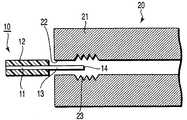
도10a 내지 도10d는 제4실시예에 따라 광섬유를 연결하는 방법을 설명하는 단면도들,10A to 10D are cross-sectional views illustrating a method of connecting optical fibers according to a fourth embodiment,
도11은 본 발명의 제5실시예에 따른 광섬유 커넥터의 구조를 나타내는 단면도,11 is a cross-sectional view showing the structure of an optical fiber connector according to a fifth embodiment of the present invention,
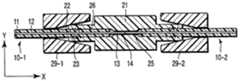
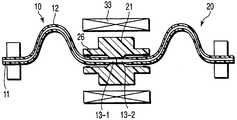
도12는 광섬유의 축에 수직한 평면을 따라 얻어지는, 본 발명의 제6실시예에 따른 광섬유 커넥터의 구조를 설명하는 단면도,12 is a sectional view for explaining a structure of an optical fiber connector according to a sixth embodiment of the present invention obtained along a plane perpendicular to the axis of the optical fiber,
도13은 안내구멍의 축방향에서 볼 때의 페룰을 도시한, 제6실시예에 따른 광섬유 커넥터의 구조를 설명하는 정면도,13 is a front view for explaining the structure of the optical fiber connector according to the sixth embodiment showing a ferrule viewed in the axial direction of the guide hole,
도14는 제6실시예에 따른 광섬유 커넥터의 구조를 설명하고 광섬유의 연결방법을 나타내는 사시도,FIG. 14 is a perspective view illustrating a structure of an optical fiber connector according to a sixth embodiment,
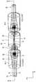
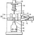
도15는 본 발명의 제7실시예에 따른 광섬유 절단장치의 전체구조를 나타내는 도면,15 is a view showing the entire structure of an optical fiber cutting apparatus according to a seventh embodiment of the present invention,
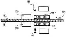
도16은 도15의 주요부를 나타내는 단면도,16 is a cross-sectional view showing the main part of Fig. 15,
도17a 내지 도17e는 본 발명의 제7실시예에 따라 광섬유를 절단하는 공정을 나타내는 단면도들이다.17A to 17E are cross-sectional views illustrating a process of cutting an optical fiber according to a seventh embodiment of the present invention.
본 발명은 광섬유를 광학적으로 연결하는 광섬유 커넥터와, 이 광섬유 커넥터를 사용하여 광섬유를 광학적으로 연결하는 광섬유 연결방법에 관한 것이다.The present invention relates to an optical fiber connector for optically connecting an optical fiber and an optical fiber connection method for optically connecting an optical fiber using the optical fiber connector.
광통신 기술 및 광전송 기술에서, 보드(board)에 장착된 LSI들 사이에 광전송라인이 형성되는 광배선(optical wiring)이 최근에 개발되었다. 이 기술에서, 광전송라인은 예컨대 광섬유나 웨이브가이드 필름(waveguide film)으로 형성된다. 현 단계에서, 웨이브가이드 필름의 전송손실은 광섬유보다 3 자릿수 또는 4 자릿수 정도까지 크다. 따라서, 비교적 긴 거리에 대해서는 광섬유를 사용하는 것이 효과적이다.In optical communication technology and optical transmission technology, optical wiring is recently developed in which an optical transmission line is formed between LSIs mounted on a board. In this technique, the optical transmission line is formed of, for example, an optical fiber or a waveguide film. At this stage, the transmission loss of the waveguide film is three or four digits larger than that of the optical fiber. Therefore, it is effective to use an optical fiber for a relatively long distance.
예컨대, 보드상의 LSI들이 광섬유에 의해 연결될 때, LSI들 사이에서 광섬유의 길이를 조정하는 것이 필요하다. 이 경우에, 광섬유의 각 끝에 광커넥터를 부착할 수 있는데, 광섬유의 각 끝을 가공(특히 연마)하는 공정에 비용이 많이 들기 때문에 비현실적이다. 대신, 기계적인 스플라이싱(splicing)이라고 불리는 방법이 효과적인바, 여기서는 연마 없이 응력파단을 이용하여 끝면을 형성하여서, 광섬유를 LSI에 반영구적으로 연결하게 된다.For example, when the LSIs on the board are connected by optical fibers, it is necessary to adjust the length of the optical fibers between the LSIs. In this case, optical connectors can be attached to each end of the optical fiber, which is impractical because of the high cost of processing (especially polishing) each end of the optical fiber. Instead, a method called mechanical splicing is effective. In this case, the end face is formed by using stress fracture without polishing, so that the optical fiber is permanently connected to the LSI.
기계적인 스플라이싱 방법으로, 일본 특허출원공개공보 평4-124606호에는 광섬유를 쉬스(sheath)라고 불리는 얇은 관에 삽입하고, 광섬유를 고정시키도록 쉬스를 크림핑(crimping:눌러서 찌그러지게 하는 것)하는 기술이 소개되어 있다. 또한, 일본 특허출원공개공보 평2-12112호에는 다른 기계적인 스플라이싱 방법이 소개되어 있는데, 여기서는 광섬유를 보유지지하기 위한 카운터 보어(counter bore)가 알루미늄으로 된 스플릿 슬리이브(split sleeve)에 형성되어 있고, 응력파단에 의해 형성된 끝면을 가진 광섬유들이 상기 카운터 보어에서 서로 접촉하도록 되어 있다. 이 상태에서, 광섬유는 서로에 대해 축방향으로 압력을 받고, 스플릿 슬리이브는 광섬유를 고정하도록 조여지게 된다. 이 방법은 연마를 필요로 하지 않고, 공구를 사용해서 광섬유들이 현장에서 연결될 수 있으며, 많은 비용이 들지 않는다.As a mechanical splicing method, Japanese Patent Application Laid-Open No. 4-124606 discloses a method of inserting an optical fiber into a thin tube called a sheath, crimping the sheath to fix the optical fiber, ) Is introduced. Japanese Patent Application Laid-open No. Hei 2-12112 discloses another mechanical splicing method in which a counter bore for holding an optical fiber is divided into a split sleeve made of aluminum And optical fibers having end faces formed by stress fracture are brought into contact with each other at the counter bores. In this state, the optical fibers are axially pressed against each other, and the split sleeves are tightened to fix the optical fibers. This method does not require polishing, and the optical fiber can be connected in the field using a tool, and is not expensive.
상기 일본 특허출원공개공보 평4-124606호에서 소개된 기술은, 광섬유의 연결 끝을 연마하는 데에 많은 비용이 들고, 각 쉬스가 찌그러져야 하기 때문에 큰 공구가 필요해서, 현장에서 연결시키는 것이 어렵다고 하는 단점이 있다. 또한, 광섬유가 쉬스에 삽입되어 그 안에 고정되기 때문에, 광섬유 고정부가 예컨대 열팽창에 의해 용이하게 이동되는 단점이 있다.The technique disclosed in Japanese Patent Application Laid-Open Publication No. 4-124606 has a problem in that it is expensive to polish the connection end of the optical fiber and a large tool is required because each of the sheaths must be squashed, . Further, since the optical fiber is inserted into the sheath and fixed in the sheath, there is a disadvantage that the optical fiber fixing portion is easily moved by, for example, thermal expansion.
한편, 상기 일본 특허출원공개공보 평2-12112호의 기술은 현장에서 처리가 가능하나, 광섬유가 알루미늄으로 된 스플릿 슬리이브에서 서로 접촉하기 때문에, 스플릿 슬리이브가 조여질 때 발생하는 변형에 의해 스플릿 슬리이브가 이동하는 것을 방지할 필요가 있다. 이를 위해서, 슬리이브의 재료의 강도를 늘리는 것이 필요한데, 이로 인해서 수지로 슬리이브를 형성하는 것이 곤란하게 된다. 또한, 슬리이브가 금속으로 형성될 때에는 슬리이브가 불가피하게 커지게 되는 단점이 있다.On the other hand, the technique of Japanese Patent Application Laid-Open No. Hei 2-12112 can be processed in the field, but since the optical fibers are in contact with each other in the aluminum split sleeves, due to the deformation that occurs when the split sleeves are tightened, It is necessary to prevent the Eve from moving. For this purpose, it is necessary to increase the strength of the material of the sleeve, which makes it difficult to form the sleeve with the resin. Further, when the sleeve is formed of a metal, there is a disadvantage that the sleeve is inevitably enlarged.
본 발명의 제1양상에 따르면, 피복재보다 더 높은 열변형온도를 가진 수지로 형성되고서, 광섬유의 팁(tip)이 서로 마주보게 위치된 상태로 광섬유가 그 안에 삽입되도록 된 안내구멍과, 상기 피복재와 함께 광섬유를 고정시키도록 상기 안내구멍의 내벽에 원주방향으로 형성된 광섬유 고정용 홈부를 포함하는 몸체를 구비하는, 피복재로 피복된 적어도 한 쌍의 광섬유를 광학적으로 연결하는 광섬유 커넥터가 제공된다.According to a first aspect of the present invention, there is provided an optical fiber connector comprising: a guide hole formed of a resin having a thermal deformation temperature higher than that of a covering material so that an optical fiber is inserted into the optical fiber with tips of the optical fibers facing each other; And a body including an optical fiber fixing groove formed in the inner wall of the guide hole so as to fix the optical fiber together with the optical fiber fixing the optical fiber. The optical fiber connector is optically connected with at least one pair of optical fibers covered with the covering member.
본 발명의 제2양상에 따르면, 피복재보다 더 높은 열변형온도를 가진 재료로 형성되고서, 광섬유의 팁이 서로 마주보게 위치된 상태로 광섬유가 그 안에 삽입되도록 된 안내구멍과, 상기 피복재와 함께 광섬유를 고정시키도록 상기 안내구멍의 내벽에 원주방향으로 형성된 광섬유 고정용 홈부를 포함하는 몸체를 구비하되, 상기 광섬유의 피복재가 열변형될 때 상기 피복재의 일부가 홈부에 의해 물려져서 상기 안내구멍에 있는 광섬유를 고정시키는, 피복재로 피복된 적어도 한 쌍의 광섬유를 광학적으로 연결하는 광섬유 커넥터가 제공된다.According to a second aspect of the present invention, there is provided an optical fiber connector comprising: a guide hole which is formed of a material having a higher thermal deformation temperature than a cover material and into which an optical fiber is inserted so that tips of the optical fiber are positioned opposite to each other; Wherein a part of the cover is hooked by the groove when the cover of the optical fiber is thermally deformed so that the cover is fixed to the guide hole, There is provided an optical fiber connector for optically connecting at least a pair of optical fibers coated with a covering material for fixing the optical fibers.
본 발명의 제3양상에 따르면, 피복재보다 더 높은 열변형온도를 가진 재료로 형성되고서, 광섬유의 팁이 서로 마주보게 위치된 상태로 광섬유가 그 안에 삽입되도록 된 안내구멍과, 상기 피복재와 함께 광섬유를 고정시키도록 상기 안내구멍의 내벽에 원주방향으로 형성된 광섬유 고정용 홈부를 포함하는 몸체를 구비한 광섬유 커넥터를 준비하는 단계와; 상기 광섬유의 팁의 끝면을 노출시키는 단계; 상기 광섬유의 팁의 끝면이 서로 마주보게 된 상태로 적어도 한 쌍의 광섬유를 상기 안내구멍의 양쪽으로부터 상기 광섬유 커넥터의 안내구멍으로 삽입하는 단계; 상기 안내구멍에 광섬유를 고정시키기 위해, 홈부에서 상기 피복재와 이 피복재의 두 물림부가 열변형되도록 광섬유가 상기 안내구멍으로 삽입될 때 또는 그 후에 광섬유를 피복하는 피복재를 가열하는 단계;를 포함하는, 피복재로 피복된 적어도 한 쌍의 광섬유를 광학적으로 연결하는 방법이 제공된다.According to a third aspect of the present invention, there is provided an optical fiber connector, comprising: a guide hole formed of a material having a thermal deformation temperature higher than that of a covering material so that an optical fiber is inserted into the optical fiber with the tips of the optical fiber facing each other; Preparing an optical fiber connector having a body including an optical fiber fixing groove formed in an inner wall of the guide hole in a circumferential direction so as to fix the optical fiber connector; Exposing an end surface of the tip of the optical fiber; Inserting at least one pair of optical fibers into the guide hole of the optical fiber connector from both sides of the guide hole with the end faces of the optical fiber facing each other; Heating the covering material covering the optical fiber when the optical fiber is inserted into the guide hole or after the optical fiber is thermally deformed so that the covering material and the two pieces of the covering material in the groove portion are thermally deformed to fix the optical fiber to the guide hole. There is provided a method of optically connecting at least a pair of optical fibers covered with a covering material.
삭제delete
삭제delete
삭제delete
본 발명의 제4양상에 따르면, 다수의 광섬유를 보유지지하도록 된 페룰(ferrule)과; 광섬유의 축에 수직한 방향 및 평행한 방향으로 상기 페룰에 압력을 가하도록 된 크림핑부재;를 포함하는, 적어도 한 쌍의 광섬유를 광학적으로 연결하는 광섬유 커넥터가 제공된다.According to a fourth aspect of the present invention, there is provided a fiber optic device comprising: a ferrule adapted to hold a plurality of optical fibers; There is provided an optical fiber connector for optically connecting at least a pair of optical fibers including a crimping member adapted to apply pressure to the ferrule in a direction perpendicular to the axis of the optical fiber and in a parallel direction.
이하, 본 발명의 실시예가 첨부도면을 참조로 하여 상세하게 설명된다. 도면에서, 같은 참조부호는 같은 부재를 나타낸다. 도면은 개략적인 것으로, 두께와 평면의 치수 및 층두께의 백분율 등의 관계는 실제에서 달라질 수 있다. 따라서, 특정한 두께와 치수는 아래의 설명을 고려하여 결정되어야 한다. 치수의 관계나 비율은 도면 사이에서도 달라질 수 있다.Hereinafter, embodiments of the present invention will be described in detail with reference to the accompanying drawings. In the drawings, like reference numerals designate like elements. The drawings are schematic, and the relationship between the thickness and the dimensions of the plane and the percentage of the layer thickness, etc. may vary in practice. Therefore, specific thicknesses and dimensions should be determined taking into consideration the following description. The relationship or proportions of dimensions can also vary between drawings.
또한, 아래에서 설명될 실시예는 단지 본 발명의 기술사상을 구체화하기 위한 장치와 방법을 예로 든 것으로, 각 구성부재의 재료와, 형상, 구조, 배치 등은 특정하게 한정되지 않는다. 본 발명의 기술사상은 청구범위의 범주 내에서 벗어나지 않고서 다양하게 변경될 수 있다.In addition, the embodiments described below merely exemplify an apparatus and method for embodying the technical idea of the present invention, and the material, shape, structure, arrangement, and the like of each constituent member are not particularly limited. The technical spirit of the present invention can be variously changed without departing from the scope of the claims.
또한, 아래에서 설명되는 실시예의 광섬유 커넥터는 광섬유를 연결한 후에, 광섬유 스플라이싱과 같은 연결이 이루어지기 전의 상태로 되돌릴 수 없다.In addition, the optical fiber connector of the embodiment described below can not be returned to the state before connection such as optical fiber splicing is performed after the optical fiber is connected.
(제1실시예)(Embodiment 1)
도1은 본 발명의 제1실시예에 따른 광섬유 커넥터의 구조를 나타내는 단면도이다.1 is a cross-sectional view showing the structure of an optical fiber connector according to a first embodiment of the present invention.
도1에서, 참조부호 10(10-1,10-2)은 광섬유를 나타낸다. 각 광섬유(10)는 코어(11)를 피복재(12)로 덮어씌워서 형성된다. 코어는 수정이나 플라스틱으로 형성될 수 있다. 피복재(12)는 굽힘력 및 마찰력과 같은 외력에 대한 광섬유의 내구성을 증가시키는 주 피복재이다. 피복재(12)는 자외선 경화 수지나 연질 플라스틱 또는 폴리아미드 수지 등으로 이루어진 단층 또는 다층으로 형성될 수 있다.In Fig. 1, reference numeral 10 (10-1, 10-2) denotes an optical fiber. Each of the
각 광섬유(10)의 끝부로부터 피복재(12)의 일부가 제거된 후에(도면에서 참조부호 13은 피복재(12)가 제거된 광섬유(10)의 끝부를 나타낸다), 각 광섬유(10)의 끝면은 응력파단을 사용하여 형성된다. 이 상태에서, 광섬유(10)는 나중에 설명되는 페룰의 안내구멍으로 양쪽에서 삽입되어, 광섬유의 끝면들이 서로 접촉하게 된다.After the part of the
도1에서, 참조부호 20은 광섬유 커넥터를 나타낸다. 광섬유 커넥터(20)는 위치선정용 안내구멍(22)과, 이 안내구멍(22)의 내면에 구비되는 광섬유 고정용 홈부(23)로 이루어진 원통형 페룰(21;몸체)로 형성된다.In Fig. 1,
페룰(21)은 지르코니아(zirconia), 유리, 에폭시 수지, 폴리페닐렌설파이드(polyphenylene sulfide;PPS) 수지, 폴리에틸렌테레프탈레이트(polyethylene terephthalate;PBT) 수지, 페놀 수지, 폴리에스테르 수지, 폴리이미드(polyimide) 수지, 탄화불소(fluorocarbon resin) 수지나, 액정 폴리머 등과 같은 세라믹재료와 알루미늄으로 만들어질 수 있다. 내열온도(이 경우에, 각 재료의 굽힙탄성계수가 실온에서의 굽힙탄성계수의 절반이나 그 이하인 가장 낮은 온도)가, 광섬유(10)의 피복재(12)가 열변형되는 온도보다 높으면 된다. 특히, 페룰이 약 5㎛ 내지 30㎛ 두께의 유리 충전재가 70% 내지 80% 혼합된 에폭시 수지로 형성된다면, 안내구멍(22)은 금속주형을 사용하는 수지성형으로 용이하게 형성될 수 있다.The
안내구멍(22)은 페룰의 축방향으로 페룰(21)의 중앙을 관통하여 뻗으며, 광섬유(10)의 외경보다 1㎛ 내지 2㎛ 정도 큰 내경을 가진다. 홈부(23)는 안내구멍(22)의 양끝 근처에 위치된다. 각 홈부(23)는 안내구멍(22)의 내면에 형성되고서 원주방향으로 뻗은 V자 모양의 단면을 가지는 다수의 홈을 가진다.The
도2a 내지 도2c는 제1실시예 따라 광섬유를 연결하는 방법을 설명하는 단면도들이다.2A to 2C are cross-sectional views illustrating a method of connecting optical fibers according to a first embodiment.
도2a에 도시된 바와 같이, 피복재(12)가 각 광섬유(10)의 끝부(13)에서 제거되어, 광입출력 끝면(14)을 형성한다. 끝면(14)은 예컨대 응력파단 등에 의해 형성되고 광학적인 끝면으로서 작용한다. 페룰(21)의 안내구멍(22)은 예컨대 1㎛의 직경을 갖는데, 이 직경은 각 광섬유(10)의 직경보다 약간 크다. 안내구멍(22)은 그 내면에 형성된 홈부(23)를 가져서 이 홈부는 내면으로부터 돌출되지 않는다.The
도2b에 도시된 바와 같이, 끝면이 형성된 광섬유(10) 중 하나가 안내구멍(22)으로 삽입된다. 이때, 삽입된 광섬유(10)의 피복재(12)의 일부가 홈부(23) 중 하나에 보유지지된다. 이 상태에서, 다른 광섬유(10)가 반대쪽으로부터 안내구멍(22)으로 삽입되어, 광섬유(10)의 끝면(14)들이 서로 접촉한다. 이 상태에서, 광섬유(10)는 외부로부터 서로에 대하여 압력을 받는 상태로 보유지지된다.As shown in Fig. 2B, one of the
이 상태에서, 형성된 조립체가 가열되면, 각 광섬유의 피복재(12)가 열적으로 팽창하게 되어서, 도2c에 도시된 바와 같이 대응하는 홈부(23)를 채우게 된다. 그러므로, 광섬유(10)는 이들의 끝면이 서로 견고하게 접촉된 상태로 고정된다.In this state, when the formed assembly is heated, the covering
만약, 홈부(23)의 내경이 광섬유(10)의 피복재(12)의 외경보다 크면, 광섬유(10)는 더 부드럽게 삽입될 수 있지만, 이렇게 삽입된 광섬유(10)의 피복재(12)는 도2b에 도시된 바와 같이 홈부(23)에 의해 고정되지 못한다. 이 경우에는, 다음 공정에서 다른 광섬유(10)를 삽입하고 나서, 삽입된 양쪽 광섬유(10)를 가열하여 서로에 대해 압력을 받게 한다. 그 결과, 광섬유 커넥터로 피복재를 미는 힘이 피복재(12)에 가해져, 피복재(12)의 일부가 변형되면서 도2c에 도시된 것처럼 홈부(23)를 채우게 된다. 홈부(23)의 내경이 피복재(12)의 외경보다 크면, 광섬유(10)가 부드럽게 삽입될 수 있어서, 광섬유의 끝면이 확실하게 서로 접촉될 수 있다.If the inner diameter of the
홈부(23)의 내경은 홈부의 가장 안쪽 선단의 내경을 뜻하며, 이는 안내구멍(22)의 내경과 같다. 만약, 광섬유(10)를 삽입하는 것의 부드러움이 감소될 수 있다면, 홈부(23)의 내경은 광섬유를 더 확실하게 보유지지하도록 감소될 수 있다.The inner diameter of the
도3은 홈부(23)의 변형예를 나타내는 단면도이다. 이 변형예에서, 홈부(23)는 톱니모양의 단면을 가진다. 페룰의 중심에 가깝게 위치된 각 홈의 부분은 완만하게 경사져 있고, 반대쪽 부분(바깥부분)은 광축에 대하여 수직선을 가지는 가파른 기울기를 형성한다. 이러한 모양의 홈부(23)는 광섬유가 삽입될 때 광섬유(10)에 대한 낮은 저항을 나타낸다. 또한, 열변형된 후에 홈부(23)는 킥백효과(kickback effect)를 나타내는데, 즉 광섬유(10)가 페룰에서 나오는 방향으로 높은 저항을 나타낸다.3 is a cross-sectional view showing a modified example of the
그러므로, 이러한 변형예에서, 페룰(21)에 형성되어 있고 그 내면에 고정용 홈부(23)를 가진 위치선정용 안내구멍(22)의 양끝으로부터 광섬유(10)가 페룰(21)로 삽입될 때, 광섬유(10)의 피복재(12)는 열변형되어, 피복재(12)의 일부가 홈부(23)에 의해 물리게 됨으로써 광섬유(10)를 고정하게 된다. 그 결과, 축방향 힘만 광섬유(10)의 접촉부분, 즉 광학적인 연결부에 가해지고, 방사상 힘은 가해지지 않게 된다.Therefore, in this modified example, when the
따라서, 광섬유(10)의 초기 위치이동을 방지하기 위해 강성재료로 광섬유 커넥터(20)를 형성할 필요가 없다. 또한, 광섬유 커넥터(20)는 수지로 형성될 수 있다. 이로 인해 재료의 선택범위가 넓어지며, 저렴하고 소형인 커넥터가 제공될 수 있게 된다. 또한, 피복재(12)가 열변형 가능한 온도까지 가열되면 되기 때문에, 현장에서의 처리가 비교적 용이하게 실현될 수 있다. 또한, 다른 구성품이 필요하지 않아서, 비용과 크기가 더 줄어들 수 있게 된다.Therefore, it is not necessary to form the
(제2실시예)(Second Embodiment)
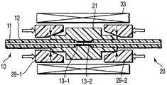
도4는 본 발명의 제2실시예에 따른 광섬유 커넥터의 구조를 나타내는 단면도이다.4 is a cross-sectional view showing the structure of an optical fiber connector according to a second embodiment of the present invention.
도4에서, 참조부호 21은 페룰(몸체)을 나타내며, 이는 기둥 몸체의 축방향으로 구멍을 내어 형성된다. 페룰(21)은 에폭시 수지나, 폴리페닐렌설파이드 수지, 폴리에틸렌테레프탈레이트 수지, 페놀 수지, 폴리에스테르 수지, 폴리이미드 수지 또는 불화탄소 수지 등으로 형성될 수 있다. 특히, 약 30㎛ 두께의 유리 충전재가 약 80% 혼합된 에폭시 수지로 페룰(21)을 형성하는 것이 바람직하다. 이 경우에, 페룰(21)은 금속주형을 사용하는 수지성형에 의해 용이하게 형성될 수 있다. 페룰(21)은 양끝을 얇게 하여 형성된 고정부(26)를 구비한다. 각 고정부(26)는 이 고정부(26)에 형성되어 있는 안내구멍(22)의 내면에 형성된 홈부(23)를 가진다. 페룰(21)이 광섬유(10)를 보유지지할 때, 홈부(23)는 광섬유(10)의 피복재(12)를 물어서 광섬유가 도4의 X축 방향으로 이동되는 것을 방지한다. 또한, 안내구멍(22)은 페룰(21)의 중앙에서 좁아지고, 이 좁아진 부분은 광섬유 안내부(25)로 작용한다.In Fig. 4,
원통형의 크림핑부재(29-1)가 X축의 양의 방향으로 페룰(21)에 끼워지고 원통형의 크림핑부재(29-2)가 X축의 음의 방향으로 페룰(21)에 끼워질 때, 고정부(26)는 안쪽으로 변형된다. 이러한 구조는 페룰(21)에 삽입된 광섬유(10)를 견고하게 고정시킨다.When the cylindrical crimping member 29-1 is fitted in the
이때, 페룰(21)을 변형시키는 이와 같은 센 힘이, 광섬유의 끝면이 서로 접촉하게 되는 페룰의 부분에는 가해지지 않는다. 그러므로, 페룰(21)이 수지와 같은 변형가능한 재료로 형성되더라도, 광섬유의 끝면은 변형되지 않아서, 연결손실(connection loss)의 상한이 처음 설계된 대로 결정될 수 있다.At this time, such a force for deforming the
도5는 제2실시예에 따른 광섬유 커넥터에 의해 실제로 연결된 광섬유의 상태를 나타내는 사시도이다. 도6은 도5의 VI-VI선에 따른 단면도이다. 도5와 도6은 하나의 광섬유를 위한 커넥터의 한 예를 나타내며, 크림핑부재(29:29-1,29-2)가 광섬유(10)의 피복재(12)를 눌러서 찌그러지게 하기 직전의 상태를 도시한다. 도면에서, 참조부호 27은 페룰(21)의 각 고정부(26)에 형성된 축방향 슬릿(slit)을 나타내고, 각 고정부(26)는 스플릿 슬리이브의 형태로 되어 있다. 크림핑부재(29)가 화살표로 표시된 바와 같이 안쪽으로 밀어부쳐지면, 고정부(26)의 내경은 감소되고 홈부(23)가 피복재(12)를 물게 된다.5 is a perspective view showing a state of an optical fiber actually connected by the optical fiber connector according to the second embodiment. 6 is a sectional view taken along the line VI-VI in Fig. Figs. 5 and 6 show an example of a connector for one optical fiber. The state before the crimping member 29 (29-1, 29-2) presses the
도5에 도시된 광섬유(10)는, 예컨대 광통신에 사용되는 수정을 기초로 한 광섬유나, 차량제어시스템에 사용되는 플라스틱을 기초로 한 광섬유(POF)가 될 수 있다. 광섬유(10)는 각각 코어(11)를 피복재(12)로 덮어씌움으로써 얻어진다. 피복재(12)는 굽힘력과 마찰력과 같은 외력에 대해서 내구성을 가져야 한다. 피복재(12)는 자외선 경화 수지나 연질 플라스틱 또는 폴리아미드 수지 등으로 이루어진 단층 또는 다층으로 형성될 수 있다.The
광섬유(10)의 각 끝부(13)는 피복재(12)로 피복되어 있지 않고, 응력파단으로 형성된 광학적인 끝면(14)을 가진다. 광섬유(10)들은 X축의 양의 방향과 음의 방향으로 각각 페룰(21)의 안내구멍(22)으로 삽입되고, 따라서 코어(11)의 끝면(14)들이 X축의 양의 방향과 음의 방향으로 각각 광섬유 안내부(25)로 삽입된다. 그 결과, 끝면(14)은 서로 접촉하게 된다. 안내구멍(22)의 내경은 광섬유(10)의 외경보다 약 1㎛ 내지 2㎛ 더 크고, 광섬유 안내부(25)의 내경은 광섬유(10)의 코어의 직경보다 약간 크다.Each
크림핑부재(29-1,29-2)가 X축의 양의 방향과 음의 방향으로 각각 광섬유(10)에 끼워질 때, 페룰(21)의 고정부(26)는 안쪽으로 변형되어 광섬유를 고정시킨다. 이 때문에, 도5에 도시된 바와 같이 크림핑부재(29)는 테이퍼진 내면을 가지며, 페룰(21)의 고정부(26)는 슬릿(27)을 가진다. 크림핑부재(29)는 수지나 금속으로 형성될 수 있으나, 비용을 줄이기 위해 크림핑부재(29)의 재료로 수지를 사용하는 것이 바람직하다. 페룰(21)은 크림핑부재(29)와 같은 재료로 형성될 수 있다. 또한, 홈부(23)가 피복재(12)를 물게 되어서, 광섬유(10)를 더 확실하게 고정시키게 되는 것이다.When the crimping members 29-1 and 29-2 are fitted in the
제2실시예의 광섬유 커넥터에서는, 광섬유(10)의 끝면 사이에 약간의 간극이 있더라도, 심각한 문제가 생기지 않게 된다. 이 경우에, 광신호의 손실 또는 반사가 약간 증가하는 경향이 있으나, 시스템이 이 경향을 반영하여 설계되면 된다.In the optical fiber connector of the second embodiment, even if there is a slight clearance between the end surfaces of the
제2실시예에 따른 구조는, 광섬유(10)를 보유지지하는 기구가 크림핑부재(29)와 같은 기계적 변형기구에 의해 이루어질 수 있어서, 커넥터 자체가 수지로 형성될 수 있게, 즉 적은 비용으로 형성될 수 있게 한다.The structure according to the second embodiment is advantageous in that the mechanism for holding the
전술된 광섬유 커넥터를 사용하여, 한 쌍의 광섬유가 다음의 방법으로 연결된다. 도7a 내지 도7c는 제2실시예에 따라 광섬유를 연결하는 방법을 설명하는 단면도들이다.Using the above-described optical fiber connector, a pair of optical fibers are connected in the following manner. 7A to 7C are cross-sectional views illustrating a method of connecting optical fibers according to a second embodiment.
먼저, 피복재(12)의 일부가 광섬유(10)로부터 제거된 후에, 이 제거로 생긴 노출부분에는 예컨대 응력파단에 의해 절단되어 노출된 광학적인 끝면(14-1,14-2)이 형성된다.First, after a part of the covering
이어서, 도7a에 도시된 바와 같이, 광섬유(10) 중 하나, 즉 광섬유(10-1)가 그 광학적인 끝면을 앞으로 하여 페룰(21)의 한쪽 안내구멍(22)으로 삽입된다. 이후에, 광섬유(10-1)의 노출된 코어(11)가 광섬유 안내부(25)로 삽입된다. 이 상태에서, 광섬유(10)는 외부의 고정기구(31)에 의해 굽혀진 상태로 유지된다. 다른 광섬유(10-2)가 페룰(21)의 다른쪽 안내구멍(22)으로 삽입된다. 이후에, 광섬유(10-1,10-2)의 끝면은 서로 접촉하게 되고, 광섬유(10-1,10-2)는 압력에 의해서 굽혀진 상태로 유지된다.7A, one of the
그 후에, 도7b에 도시된 바와 같이, 고정부(26) 주위의 페룰(21)의 일부가 가열기(33)에 의해 가열되고, 도7c에 도시된 바와 같이 미리 광섬유(10-1,10-2)에 끼워진 크림핑부재(29-1,29-2)가 X축의 양의 방향과 음의 방향으로 각각 안쪽으로 밀어부쳐진다. 그 결과, 각 슬릿(27)의 너비가 좁아져 대응하는 고정부(26)의 내경이 감소되어서, 홈부(23)가 피복재(12)를 물게 된다(도7c의 화살표 참조). 이때, 고정부(26)의 온도가 도7b에 도시된 가열공정에서 피복재(12)의 연화온도보다 높은 값으로 올라가면, 홈부(23)는 더 깊게 피복재(12)를 물 수 있게 된다. 만약 광섬유 안내부(25)와 같은, 고정부(26) 이외의 부분이 가열되지 않으면, 광섬유 안내부(25)의 변형은 억제된다. 이후에, 가열기(33)가 제거되어 전체 커넥터를 실온으로 냉각시킴으로써, 피복재(12)가 경화되어 광섬유(10-1,10-2)를 고정시키는 접착제로 작용하게 된다.7B, a part of the
일련의 공정 동안에, 광섬유 안내부(25)에는 다른 힘이나 열이 가해지는 것이 방지되어, 광섬유(10-1,10-2)의 광학적인 연결이 유지되면서 광섬유의 연결이 간단한 구조로 실현될 수 있다.During the series of processes, the
(제3실시예)(Third Embodiment)
도8을 참조로 하여 본 발명의 제3실시예가 설명될 것이다. 제3실시예는, 광섬유 안내부(25)가 직선이 아니라 구부러져 있다는 점에서 제2실시예와 다르다.A third embodiment of the present invention will be described with reference to FIG. The third embodiment is different from the second embodiment in that the optical
이러한 구조에서, 광섬유(10-1,10-2)의 끝면(14)이 서로 접촉할 때, 광섬유 자체의 좌굴력(buckling force) 때문에 X축 방향으로 잔류응력이 생기게 된다. 이 잔류응력은 끝면(14)에 계속 밀어부치는 힘을 가하여 광학적인 연결을 유지시킨다. 또한, 광섬유(10-1,10-2)가 광섬유 안내부(25)의 한쪽의 구부러진 벽을 따라 안내되기 때문에, 이들은 같은 방향(아래쪽이나 위쪽)으로 진행하여, 광섬유가 서로 접촉할 때 광섬유의 피복재의 외주의 방사상 이동은 최소로 억제될 수 있다. 즉, 광섬유가 매우 정확하게 정렬될 수 있다.In this structure, when the end faces 14 of the optical fibers 10-1 and 10-2 are in contact with each other, residual stress is generated in the X-axis direction due to a buckling force of the optical fiber itself. This residual stress applies a constant pushing force to the
(제4실시예)(Fourth Embodiment)
도9를 참조로 하여 본 발명의 제4실시예가 설명될 것이다.A fourth embodiment of the present invention will be described with reference to FIG.
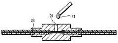
제4실시예는, 페룰(21)이 굴절률 맞춤재료(matching agent)로 작용하는 투명한 접착제를 수용하는 접착제 주입용 구멍(24)을 갖는다는 점에서 제1실시예와 다르다. 페룰(21)은 제2실시예에서와 같이 광섬유 안내부(25)와 고정부(26)를 갖추며, 접착제 주입용 구멍(24)이 고정부의 표면에서 방사상 중심부까지 고정부(26)에 형성되어 있다. 또한, 광섬유 안내부의 직경은 제2실시예에서와 같이 고정부(26)의 안내구멍(22)의 직경보다 더 작다.The fourth embodiment differs from the first embodiment in that the
제1실시예와 제2실시예에서 사용된 광섬유 연결방법에서, 페룰(21)은 가열된 후에 실온으로 냉각된다. 그러므로, 광섬유 안내부(25)는 페룰(21)의 변형에 따라 변형되어서 광섬유(10-1,10-2)의 끝면(14)이 잘못 배열되거나 접촉되지 않을 수 있다. 이에 비해, 투명한 접착제(41)인 굴절률 맞춤재료가 도9에 도시된 접착제 주입용 구멍(24)을 통해 주입되는 제4실시예에서는, 잘못된 배열이나 접촉되지 않은 상태로 인한 굴절률의 급격한 변화와, 이러한 굴절률의 급격한 변화로 생기는 끝면에서의 반사가 방지될 수 있다.In the optical fiber connection method used in the first and second embodiments, the
또한, 광섬유(10)의 연결부와 그 근처는 투명한 접착제(41)에 의해 고정된다. 투명한 접착제(41)와 페룰(21)이 수지로 형성될 때, 광섬유(10)의 끝면은 페룰의 내경과 광섬유의 외경의 차이에 상응한 정도로 서로 잘못 배열될 수 있다. 또한, 끝면들 사이에서 약간의 간극이 생기는 경우가 있을 수 있다. 물론, 이러한 잘못된 배열이나 간극이 광신호의 손실 또는 반사를 증가시킬 수 있는 경향을 반영하여 시스템을 설계해야 한다. 또한, 투명한 접착제(41)가 굴절률 맞춤재료로 작용하기 때문에, 빛의 반사를 상당히 감소시킬 수 있다.In addition, the connection portion of the
상기 구조는 광섬유(10)를 보유지지하는 기구가 광섬유(10)의 끝면(14)으로부터 떨어져 위치될 수 있게 한다. 이로 인해서, 고정부는 광섬유(10)의 연결부로부터 분리되어 위치하게 된다. 이러한 구조는, 광섬유의 연결부(광섬유의 끝면)를 서로로부터 이동시키기 않고, 고정기구가 접촉끼워맞춤기구와 같은 기계적 변형기구에 의해 이루어질 수 있게 한다. 따라서, 필요한 구성품이 예컨대 수지로 형성될 수 있어서, 저렴한 비용으로 형성될 수 있다. 또한, 광학적인 연결을 위하여 페룰에 광섬유를 끼운 후, 투명한 접착제(41)가 광섬유의 연결부 주위에서 경화되어서, 충분한 기계적 강도를 제공하게 된다.The structure allows the mechanism for holding the
도10a 내지 도10d는 제4실시예에서 사용되는 광섬유를 연결하는 방법을 나타내는 단면도들이다.FIGS. 10A to 10D are cross-sectional views illustrating a method of connecting optical fibers used in the fourth embodiment.
피복재(12)의 일부가 제거되어 한쪽 광섬유(10)의 끝부가 노출된 후에 광학적인 끝면으로 작용하는 광섬유(10)의 끝면은, 예컨대 응력파단에 의해 노출된다. 광섬유(10)의 노출된 끝면 쪽이 페룰(21)의 안내구멍(22)으로 삽입되고, 광섬유(10)는 외부의 고정기구(31)에 의해 굽혀진 상태로 유지된다. 비슷하게, 다른쪽 광섬유(10)가 반대쪽에서부터 페룰(21)의 안내구멍(22)으로 삽입된다. 이후에, 광섬유(10)의 끝면은 서로 접촉되어 광섬유(10)는 압력에 의해서 굽혀진 상태로 유지되게 된다(도10a 참조).The end face of the
다음으로, 외부의 고정기구(31)가 제거되고, 투명한 접착제(41)가 접착제 주입용 구멍(24)을 통해 페룰의 광섬유(10)의 연결부 주위로 주입된다(도10c 참조). 그 후, 투명한 접착제(41)가 경화되어 연결부와 그 근처를 완전히 고정시킨다(도10d 참조).Next, the
그러므로, 광학적으로 연결된 부분이 서로 올바르게 정렬되면서 광섬유가 연결될 수 있게 된다.Therefore, the optical fibers can be connected while the optically connected portions are properly aligned with each other.
(제5실시예)(Fifth Embodiment)
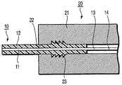
도11을 참조로 하여 본 발명의 제5실시예가 설명될 것이다. 이 실시예는 제4실시예에 크림핑부재(29:29-1,29-2)를 부가하여 얻어진다.A fifth embodiment of the present invention will be described with reference to FIG. This embodiment is obtained by adding a crimping member 29 (29-1, 29-2) to the fourth embodiment.
제5실시예에서, 외부의 크림핑부재(29)가 피복재(12)의 변형끼워맞춤을 보조하기 위해 준비되고, 연결이 완료된 후에도 있었던 곳에 남겨 진다. 도11에 도시된 바와 같이, 각 크림핑부재(29)는 테이퍼진 내경부가 있다. 크림핑부재(29)가 광섬유(10)의 축을 따라 미끄러질 때, 고정부(26)는 안쪽으로 변형되고 눌려 찌그러지게 된다. 크림핑부재(29)는 수지나 금속으로 형성될 수 있다. 비용을 감소시키기 위해 수지로 크림핑부재(29)를 형성하는 것이 바람직하다. 이 경우에, 페룰과 같은 수지가 사용될 수 있다.In the fifth embodiment, an outer crimping member 29 is prepared to assist the deformation fit of the
제5실시예에서의 제조공정은 크림핑부재(29)가 사용된다는 것을 제외하고 도10a 내지 도10d에 도시된 것과 거의 같다. 특히, 도10b에 도시된 변형단계에서, 광섬유에 미리 끼워진 크림핑부재(29)는 양쪽에서 고정부에 대하여 압력을 가하여서 홈부(23)가 피복재(12)를 물게 한다. 그 결과, 변형끼워맞춤은 더 확실하게 수행된다. 또한, 고정된 크림핑부재(29)를 있었던 곳에 남겨 둠으로써 눌러서 찌그러지게 하는 효과가 유지되어, 커넥터의 신뢰도를 더 향상시킨다.The manufacturing process in the fifth embodiment is almost the same as that shown in Figs. 10A to 10D except that the crimping member 29 is used. Particularly, in the deformation step shown in Fig. 10B, the crimping member 29 previously fitted in the optical fiber applies pressure to the fixing portion on both sides so that the
(제6실시예)(Sixth Embodiment)
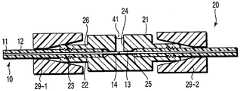
도12 내지 도14를 참조로 하여 본 발명의 제6실시예가 설명될 것이다. 제1실시예에서 제5실시예는 단일한 코어가 있는 광섬유를 사용하는 반면에, 제6실시예는 다수의 광섬유 배열을 사용한다.A sixth embodiment of the present invention will be described with reference to Figs. 12 to 14. Fig. In the first embodiment, the fifth embodiment uses an optical fiber with a single core, while the sixth embodiment uses a plurality of optical fiber arrays.
도12는 광섬유의 축에 수직한 평면을 나타내는 단면도이다. 도12에서, 참조부호 51은 코어를 나타내고, 참조부호 52는 제1피복재를 나타내며, 참조부호 53은 제2피복재를 나타낸다. 코어(51)를 제1피복재(52)로 덮어씌워 형성된 4개의 광섬유가 제2피복재(53)로 덮어씌워져서, 광섬유 배열(50)을 이룬다. 이 구조는 리본 모양으로 모아진 다수의 광섬유(코어 + 제1피복재)로 형성된 테이프 광섬유로 불린다.12 is a cross-sectional view showing a plane perpendicular to the axis of the optical fiber. In FIG. 12,
도13은 안내구멍의 축방향에서 본 페룰(61)의 정면도로서, 이는 제6실시예에서 사용된다. 참조부호 66은 페룰(61)의 양끝을 좁혀서 얻어진 고정부를 나타낸다. 슬릿(67)은 각 고정부(66)에 형성되어 있다. 또한, 참조부호 62는 그 안에 광섬유 배열(50)을 삽입하기 위한 안내구멍을 나타내고, 참조부호 65는 그 안에 광섬유 배열(50)의 코어(51)를 삽입하기 위한 광섬유 안내부를 나타낸다.13 is a front view of the
도14는 광섬유가 제6실시예에 따른 광섬유 커넥터에 의해 연결되는 상태를 나타내는 사시도이다. 제1실시예에서와 같이, 광섬유를 고정시키기 위한 홈부(63)가 안내구멍(62)의 개구부 근처에 형성되어 있다. 또한, 제1실시예에서와 같이, 광섬유 배열(50)은 그 광학적인 끝면이 노출된 후에 안내구멍(62)에 삽입된다. 코어(51)는 각 광섬유 안내부(65)로 삽입되어 그 안에서 고정된다. 이때, 형성된 구조물은 열처리 되어, 광섬유 배열(50)의 제2피복재(53)를 열변형시켜서, 광섬유 배열(50)을 홈부(63)에 보유지지하게 된다. 또한, 크림핑부재를 사용함으로써 더 확실한 고정을 실현할 수 있게 된다. 설명을 용이하게 하기 위해, 도14에서는 단지 하나의 광섬유 배열(50)만을 나타내었는데, 다른 광섬유 배열이 반대쪽에서 삽입되게 된다.14 is a perspective view showing a state where the optical fiber is connected by the optical fiber connector according to the sixth embodiment. A
(제7실시예)(Seventh Embodiment)
제7실시예는 응력파단을 사용하여 광섬유의 끝면을 형성하는 장치와 방법에 관한 것으로, 이들은 전술된 각각의 실시예에 사용된다.The seventh embodiment relates to an apparatus and a method for forming end faces of an optical fiber using stress fracture, which are used in the respective embodiments described above.
예컨대, 일본 특허 제3424527호에는, 광섬유의 피복재를 자동으로 제거하고 응력파단을 사용하여 끝면을 형성하는 장치를 소개하고 있다. 이 방법에서는, 광섬유의 피복재를 제거한 후, 피복재가 없는 광섬유가 상부 조임구와 하부 조임구에 의해 고정된다. 그 후에, 새김눈형성용 블레이드가 미끄럼이동되어 광섬유에 새김눈을 형성한다. 받침유니트(chock unit)가 새김눈에 대하여 밀어부쳐져서, 광섬유가 파단되고 그 끝면을 형성하게 된다. 절단될 때 광섬유가 상부 조임구와 하부 조임구에 의해 고정되기 때문에, 절단압력과 형성된 새김눈의 깊이가 정확하게 제어될 수 있다. 따라서, 수직한 끝면이 형성될 수 있고, 이로 인해 우수한 광학적인 끝면이 얻어질 수 있다.For example, Japanese Patent No. 3424527 discloses an apparatus for automatically removing a cover material of an optical fiber and forming an end surface using stress fracture. In this method, after removing the covering material of the optical fiber, the optical fiber without the covering material is fixed by the upper tightening means and the lower tightening means. Thereafter, the blade for forming a nick is slid to form a nick in the optical fiber. A chock unit is pushed against the nick to break the optical fiber and form its end face. Since the optical fiber is fixed by the upper fastener and the lower fastener when cut, the cutting pressure and the depth of the formed nick can be accurately controlled. Thus, a vertical end surface can be formed, whereby an excellent optical end surface can be obtained.
그러나, 광섬유의 연결끝을 처리하기 위한 전술된 장치에서는, 피복재가 제거된 후 광섬유를 조임고정해야 하는데, 이로 인해서 제거될 피복재의 길이("여분길이"라 한다)는 조임구가 광섬유를 조임고정할 수 있게 충분한 값으로 설정되어야 한다. 그러므로, 여분길이가 길어야 한다.However, in the above-described apparatus for treating the connection end of an optical fiber, the length of the cover material to be removed (referred to as "extra length") must be such that the fastener fixes the optical fiber It should be set to a value sufficient to do so. Therefore, the extra length should be long.
한편, 비슷한 방법이, 일본의 86년도 전자통신학회 전국대회의 9 ~ 182페이지에 기록된 "고강도 연결용 자동 광섬유 절단기의 개발"에 소개되어 있다. 이 방법에서는, 피복재를 제거하지 않고서 광섬유에 새김눈을 형성하고, 광섬유를 파단시킨 후에 피복재를 광섬유에서 제거한다. 파단 후에 피복재가 제거되기 때문에, 광섬유는 그 끝 근처에서 절단될 수 있다. 그러므로, 원하는 길이의 피복재가 파단 후에 잘려질 수 있어서 이용효율이 향상된다.On the other hand, a similar method is introduced in "Development of automatic fiber cutters for high-strength connections", which is recorded on pages 9-182 of Japan's 86th National Conference of Electronics and Telecommunications. In this method, a notch is formed in the optical fiber without removing the covering material, and the covering material is removed from the optical fiber after breaking the optical fiber. Since the covering material is removed after rupture, the optical fiber can be cut near its end. Therefore, the covering material having a desired length can be cut after the fracture, thereby improving the utilization efficiency.
그러나, 이 방법에서는, 피복재가 있는 상태에서 광섬유에 새김눈이 형성되어야 한다. 따라서, 절단압력을 증가시켜야 하고, 이로 인해 새김눈이 크게 형성되며 새김눈의 크기가 불규칙하게 될 수 있다. 이 때문에, 파단 후에 광섬유의 끝면을 매끄럽게 하는 것이 어려워지고, 끝면에서 난반사를 일으킬 수 있게 된다. 또한, 새김눈의 크기가 초기의 절단단계에서 매우 불규칙하게 될 수 있기 때문에, 새김눈을 형성하는 동안 새김눈에 대하여 광섬유의 좌우부분에 축방향 인장력을 부여하는 것이 필요하다. 이는 절단기의 구조를 복잡하게 하여, 크기와 비용이 증대되게 한다.However, in this method, it is necessary to form a nick in the optical fiber in the presence of the covering material. Therefore, the cutting pressure must be increased, which results in a large scoring and irregular size of the scoring. Therefore, it becomes difficult to smooth the end face of the optical fiber after the fracture, and diffuse reflection can be caused at the end face. In addition, since the size of the nicks can become very irregular in the initial cutting step, it is necessary to apply an axial tensile force to the left and right portions of the optical fiber with respect to the nicks during formation of the nicks. This complicates the structure of the cutter, resulting in increased size and cost.
이에 비해, 제7실시예는 저렴한 비용으로 광섬유의 피복재의 여분길이를 최소화할 수 있고 소형으로 만들어질 수 있는 광섬유 절단장치를 제공하며, 이 절단장치에서 사용되는 광섬유 절단방법을 제공한다.In contrast, the seventh embodiment provides an optical fiber cutting apparatus that can minimize the extra length of the covering material of the optical fiber at low cost and can be made compact, and provides a method for cutting an optical fiber used in the cutting apparatus.
도15와 도16은 제7실시예에 따른 광섬유 절단장치의 주요부를 설명하는 도면들이다. 특히, 도15는 개략도이고 도16은 단면도이다.FIGS. 15 and 16 are views for explaining the main part of the optical fiber cutting apparatus according to the seventh embodiment. Particularly, Fig. 15 is a schematic view and Fig. 16 is a sectional view.
도면에서, 참조부호 131은 상부 조임구를 나타내고, 참조부호 132는 하부 조임구를 나타낸다. 상부 조임구와 하부 조임구는 제1조임구(130)를 구성한다. 제1조임구(130)는 피복재와 함께 광섬유를 조임고정한다. 제1조임구(130)는 광섬유에 손상을 가하지 않는 고무나 연질 플라스틱과 같은 연질재료로 형성된다. 제1조임구(130)는 소정 압력으로 광섬유를 보유지지하여, 광섬유의 피복재를 제거하거나 광섬유를 파단시키기 위해 축방향 힘이 가해질 때 광섬유가 이동하지 않게 한다.In the figure,
스트립퍼(110;stripper)는 결합된 블레이드 지지부(111,112)로 형성되어, 지지점 주위로 선회할 수 있게 되어 있다. 블레이드 지지부(111,112)는 이 블레이드 지지부(111,112)에 장착된 블레이드(120)를 약 80℃ 내지 120℃까지 가열하는 가열기를 각각 내장하여서, 광섬유의 피복재가 용이하게 제거될 수 있다. 블레이드(120)는 높은 경도와 내구성을 가지는 스테인리스강이나 알루미늄 합금과 같은 재료로 형성된다. 전체 스트립퍼(110)는 이동나사(113)에 의해 도15의 좌우로 미끄럼이동될 수 있다.The
블레이드(120)가 광섬유(181)에 도달하기 직전의 깊이까지 광섬유(181)의 피복재(182)의 일부를 물도록 한 후, 스트립퍼(110)가 광섬유(181)의 파단영역으로부터 멀리 이동하여(즉, 도15에서 오른쪽으로 이동하여), 피복재(182)의 일부를 벗겨낸다. 도16에서 참조부호 170은 피복재(182)가 스트립퍼(110)에 의해 제거된 광섬유(181)의 노출부를 나타낸다. 상기 "피복재의 일부"는 광섬유(181)의 파단될 부분을 포함하고서, 약 2mm의 축방향 길이를 가진 매우 좁은 부분이다. 이 "피복재의 일부"는, 나중에 설명되는 제2조임구에 의해 조임고정되는 광섬유(181)의 부분은 포함하지 않는다. 벗기는 공정이 끝난 후, 블레이드 지지부(111,112)는 각각 위아래로 크게 열리고, 도15의 오른쪽으로 후퇴될 수 있다.The
제2조임구(140)는 상부 조임구(141)와 하부 조임구(142)로 이루어져 있다. 스트립퍼(110)가 작동될 때, 상부 조임구(141)와 하부 조임구(142)는 각각 위아래로 크게 열리고, 후퇴위치에 위치된다. 스트립퍼(110)는, 광섬유의 피복재가 소정의 간격(광섬유가 피복재와 함께 파단되는 것이 방지되기에 충분해야 한다)으로, 예컨대 축방향으로 약 2mm 정도로 제거될 때, 블레이드(120)가 도15의 오른쪽으로 후퇴되도록 설치된다. 스트립퍼(110)가 후퇴된 후, 상부 조임구(141)와 하부 조임구(142)는 일부 제거된 피복재와 함께 광섬유를 고정시킨다.The
새김눈형성용 블레이드(160)는 WC-초경합금이나 소결 다이아몬드 등으로 형성되고, 블레이드홀더(162)에 레일(163)을 매개로 하여 도15에서 수직으로 이동가능하게 고정되어 있다. 새김눈형성용 블레이드(160)가 블레이드홀더(162)의 이동에 따라 수직으로 이동할 때, 이 블레이드가 광섬유에 미소한 새김눈을 형성한다. 경질 고무나 연질 플라스틱으로 이루어진 받침유니트(151)가 광섬유의 새김눈에 대하여 밀어부쳐지면, 광섬유가 소성파괴에 의해 파단된다. 참조부호 152는 받침유니트를 해제하기 위한 스프링을 표시하고, 참조부호 153은 받침유니트를 작동시키는 버튼을 표시한다. 버튼(153)을 누르면, 받침유니트(151)가 광섬유에 대하여 아래쪽으로 밀어부쳐져 소성파괴에 의해 광섬유를 파단시키게 된다. 소성파괴에 의해 광섬유를 파단시키기 위해서, 제1조임구(130)와 제2조임구(140)는 소정 간격으로 서로 떨어져 있어야 한다.The
제7실시예의 광섬유 절단장치에서는, 피복재가 조임고정되기 때문에, 피복재(182)를 제거하여 노출된 광섬유(181)의 부분의 폭이, 새김눈형성용 블레이드(160)가 광섬유에서 새김눈을 형성할 수 있는 정도의 크기로 설정되면 된다. 따라서, 소성파괴에 의한 광섬유(181)의 파단 후에 피복재(182)가 제거된 광섬유(181)의 노출부의 길이는 최소화될 수 있는데, 예컨대 스플라이싱에 의해 광섬유 연결부가 소형화될 수 있다. 또한, 예컨대 다수의 광섬유가 제2피복재로 덮어씌워진 테이프 광섬유가 파단되면, 제거될 피복재가 남겨진 상태로 절단되어서, 광섬유들이 서로 분리되는 것이 방지된다. 그러므로, 테이프 광섬유의 취급성이 향상되고, 파단 후에 예컨대 먼지제거가 용이하게 수행될 수 있다.In the optical fiber cutting apparatus of the seventh embodiment, since the cover material is tightened and fixed, the
이하에서, 도17a 내지 도17e를 참조로 하여 전술된 광섬유 절단장치를 사용하여 광섬유를 절단하는 방법을 설명한다.Hereinafter, a method of cutting an optical fiber using the above-described optical fiber cutting apparatus with reference to Figs. 17A to 17E will be described.
먼저, 도17a에 도시된 바와 같이, 제1조임구(130)가 피복재(182)와 함께 광섬유(181)를 조임고정한 후, 스트립퍼(110)의 블레이드(120)가 피복재(182)의 일부를 물게 된다.17A, after the
이어서, 도17b에 도시된 바와 같이, 스트립퍼(110)가 광섬유의 끝쪽(도17b에서 오른쪽)으로 이동하여, 피복재(182)의 일부를 제거한다. 참조부호 170은 피복재(182)를 제거하여 노출된 광섬유(181)의 노출부를 표시한다. 참조부호 183은 피복재(182)의 제거된 부분을 표시한다.Then, as shown in Fig. 17B, the
이후, 도17c에 도시된 바와 같이, 노출부(170)가 소정의 간격까지 도달하면, 스트립퍼(110)의 블레이드 지지부(111,112)가 수직으로 크게 열려서, 광섬유(181)를 따라 도17c의 오른쪽으로 후퇴한다. 그 후에, 제2조임구(140)가 피복재의 제거된 부분(183)과 함께 광섬유(181)를 조임고정한다. 이때, 제2조임구(140)는, 광섬유(181)가 휘어지고 소성파괴에 의해 파단될 수 있는 간격만큼 제1조임구(130)로부터 떨어져 있어야 하는데, 제7실시예에서 이 간격은 약 10mm로 설정된다.17C, when the exposed
이어서, 도17d에 도시된 바와 같이, 새김눈형성용 블레이드(160)가 광섬유(181)의 노출부(170)와 접촉하여서, 광섬유(181)에 미소한 새김눈을 형성한다(이 실시예에서는, 약 5㎛ 내지 10㎛의 깊이를 가진 새김눈이 형성된다).17D, the
마지막으로, 도17e에 도시된 바와 같이, 받침유니트(151)가 광섬유(181)의 노출부(170)에 대하여 아래쪽으로 밀어부쳐져서, 소성파괴에 의해 광섬유를 파단시키게 된다.Finally, as shown in FIG. 17E, the
이 실시예의 방법은, 피복재(182)가 스트립퍼(110)에 의해 제거될 때, 광섬유(181)를 파단하기 위해 필요한 피복재(182)의 일부가 남겨지고, 광섬유(181)가 제2조임구(140)에 의해 조임고정된 피복재(182)의 남겨진 부분과 함께 파단되는 점이 특징이다. 그 결과, 광섬유의 끝면을 형성하는 데에 필요한 피복재의 여분길이는 최소화될 수 있다. 노출부(170)의 길이는, 새김눈형성용 블레이드(160)가 광섬유와 접촉할 수 있는 크기로 설정되면 된다. 이 길이는 약 2mm로 설정될 수 있다. 이 경우에, 새김눈이 노출부(170)의 중앙부분에 형성된다면, 파단 후 광섬유의 노출부(170)의 길이는, 상기 노출부(170) 길이의 절반인 약 1mm의 아주 작은 값으로 될 수 있다. 따라서, 제7실시예의 장치에 의해 만들어진 광섬유들이 연결된다면, 필요한 커넥터의 크기가 줄어들 수 있다.The method of this embodiment is such that when the
전술된 바와 같이, 광섬유 파단영역 근처의 피복재가 스트립퍼에 의해 제거된 후에 스트립퍼는 광섬유로부터 분리된다. 그러므로, 광섬유의 여분길이는, 스트립퍼를 분리시키는 것 대신에 광섬유의 축을 따라 스트립퍼를 이동시키는 방법에 비하여, 적은 비용으로 최소화될 수 있다. 또한, 피복재가 제거된 후, 새김눈이 광섬유의 표면에 형성되고, 이어서 광섬유가 소성파괴에 의해 파단됨으로써, 아주 신뢰성 있고 소형인 절단장치가 만들어질 수 있다.As described above, after the cover material near the optical fiber rupture area is removed by the stripper, the stripper is separated from the optical fiber. Therefore, the extra length of the optical fiber can be minimized at low cost, compared with a method of moving the stripper along the axis of the optical fiber instead of separating the stripper. Further, after the covering material is removed, the nicks are formed on the surface of the optical fiber, and then the optical fiber is broken by the plastic fracture, so that a very reliable and compact cutting apparatus can be made.
(변형예)(Modified example)
전술된 실시예들은 단순히 본 발명의 기술사상을 구체화하기 위한 장치나 방법의 예를 들어 설명하기 위한 것으로, 이 기술사상은 실시예에서 설명된 재료나, 모양, 구조, 배치 등에 한정되지 않는다. 본 발명은 그 범주에서 벗어나지 않는 다양한 방법으로 변경될 수 있다.The above-described embodiments are merely illustrative of an apparatus or method for embodying the technical idea of the present invention, and the technical idea is not limited to the material, shape, structure, arrangement and the like described in the embodiment. The present invention may be modified in various ways without departing from the scope thereof.
예컨대, 실시예에서 사용된 페룰이나 크림핑부재의 모양은 동축의 것으로 한정되지 않고, 평행한 평판 형태와 같은 다른 모양을 가질 수 있다. 또한, 홈부는 동축의 홈으로 한정되지 않고, 원주상으로 배열된 딤플(dimple)로 형성될 수 있다.For example, the shapes of the ferrules or crimping members used in the embodiments are not limited to coaxial, but may have other shapes, such as parallel plate shapes. Further, the groove portion is not limited to the coaxial groove, but may be formed by a dimple arranged in a circumferential direction.
당해업자는 추가의 장점과 응용을 용이하게 알 수 있다. 그러므로, 더 넓은 관점에서 본 발명은 여기에 도시되고 설명한 특정한 실시예에 한정되지 않는다. 따라서, 청구범위에 의해 정의된 본 발명의 정신과 범주에서 벗어나지 않는 다양한 변경이 이루어질 수 있다.The skilled artisan can readily ascertain additional advantages and applications. Therefore, the invention in its broader aspects is not limited to the specific embodiments shown and described herein. Accordingly, various modifications may be made without departing from the spirit and scope of the invention as defined by the appended claims.
이상과 같이 본 발명에 의하면, 현장에서 가공할 수 있으며 저렴하고 소형화가 가능한 광섬유 커넥터와 광섬유의 연결방법을 제공하는 효과가 있게 된다.As described above, according to the present invention, it is possible to provide a method of connecting an optical fiber connector and an optical fiber which can be processed in the field and which is inexpensive and can be miniaturized.
Claims (25)
Translated fromKoreanApplications Claiming Priority (6)
| Application Number | Priority Date | Filing Date | Title |
|---|---|---|---|
| JP2004089300 | 2004-03-25 | ||
| JPJP-P-2004-00089300 | 2004-03-25 | ||
| JP2004108060AJP2005292499A (en) | 2004-03-31 | 2004-03-31 | Optical fiber manufacturing method and manufacturing apparatus thereof |
| JPJP-P-2004-00108060 | 2004-03-31 | ||
| JP2004287959AJP2005309367A (en) | 2004-03-25 | 2004-09-30 | Optical fiber connector, optical fiber connector, and optical fiber connection method |
| JPJP-P-2004-00287959 | 2004-09-30 |
Publications (2)
| Publication Number | Publication Date |
|---|---|
| KR20060044703A KR20060044703A (en) | 2006-05-16 |
| KR100707563B1true KR100707563B1 (en) | 2007-04-13 |
Family
ID=34989900
Family Applications (1)
| Application Number | Title | Priority Date | Filing Date |
|---|---|---|---|
| KR1020050024640AExpired - Fee RelatedKR100707563B1 (en) | 2004-03-25 | 2005-03-24 | Optical fiber connector and connecting method |
Country Status (4)
| Country | Link |
|---|---|
| US (1) | US7314317B2 (en) |
| KR (1) | KR100707563B1 (en) |
| CN (1) | CN100406941C (en) |
| TW (1) | TWI266915B (en) |
Families Citing this family (29)
| Publication number | Priority date | Publication date | Assignee | Title |
|---|---|---|---|---|
| BRPI0612362A2 (en)* | 2005-04-22 | 2010-11-03 | Ilsin Tech Co Ltd | portable fiber optic processing apparatus |
| JP2007107658A (en)* | 2005-10-14 | 2007-04-26 | Pentax Corp | Insert member fixing structure |
| JP4349372B2 (en)* | 2006-01-25 | 2009-10-21 | ミツミ電機株式会社 | Optical module and optical module manufacturing method |
| JP4864658B2 (en) | 2006-11-21 | 2012-02-01 | 株式会社東芝 | Optical fiber connection method |
| JP3955617B1 (en)* | 2007-01-10 | 2007-08-08 | 耕三 山野井 | Mechanical splice |
| JP5297025B2 (en)* | 2007-11-20 | 2013-09-25 | 住友電気工業株式会社 | Optical connector and method of mounting optical connector on coated optical fiber |
| DE102007062658A1 (en)* | 2007-12-24 | 2009-06-25 | Bktel Communications Gmbh | Hybrid connection |
| DE102008062848A1 (en)* | 2008-12-23 | 2010-06-24 | Jt Optical Engine Gmbh + Co. Kg | Splice connection between two optical fibers and method for producing such a splice connection |
| ES2366510B1 (en)* | 2008-12-30 | 2012-09-07 | Airbus Operations, S.L. | OPTICAL FIBER CONNECTION DEVICE FOR COMPOSITE MATERIAL STRUCTURES. |
| US9268091B2 (en)* | 2010-02-18 | 2016-02-23 | Corning Cable Systems Llc | Methods for laser processing arrayed optical fibers along with splicing connectors |
| US20110267598A1 (en)* | 2010-04-30 | 2011-11-03 | Vestas Wind Systems A/S | Optical sensor system and detecting method for an enclosed semiconductor device module |
| KR101038195B1 (en)* | 2010-07-08 | 2011-06-01 | 박찬설 | Fiber Optic Connector and How to Assemble It |
| JP5357231B2 (en)* | 2010-12-15 | 2013-12-04 | 三菱鉛筆株式会社 | Optical connector |
| CN102173793B (en)* | 2011-03-16 | 2013-04-24 | 辽宁爱尔创生物材料有限公司 | Zirconia ceramic casing pipe and preparation process thereof |
| US20130315542A1 (en)* | 2012-03-11 | 2013-11-28 | Hoya Corporation Usa | Connector assembly for optical fiber |
| JP6018437B2 (en) | 2012-06-29 | 2016-11-02 | オムロン株式会社 | Optical fiber type photoelectric switch head |
| CN102729395B (en)* | 2012-07-13 | 2014-09-10 | 常州市新盛电器有限公司 | Production method of fiber arrays |
| US8915654B2 (en)* | 2012-10-16 | 2014-12-23 | Verizon Patent And Licensing Inc. | Optical multi-port connectors |
| US9256031B2 (en)* | 2012-11-02 | 2016-02-09 | Tyco Electronics Corporation | Terminus assembly for terminating an optical cable |
| US9084652B2 (en)* | 2013-03-13 | 2015-07-21 | Ultimate Wireforms, Inc. | Archwire assembly with non-linear crimpable orthodontic stop and method of manufacture |
| TWI464472B (en)* | 2013-03-15 | 2014-12-11 | Protai Photonic Co Ltd | Back post for optical fiber connector |
| US8764316B1 (en) | 2013-05-23 | 2014-07-01 | Corning Cable Systems Llc | Fiber optic connector with vented ferrule holder |
| JP6383617B2 (en) | 2014-09-11 | 2018-08-29 | 株式会社フジクラ | Optical fiber connection structure, optical fiber connector |
| JP6557052B2 (en)* | 2015-04-30 | 2019-08-07 | 三和電気工業株式会社 | Optical connector ferrule |
| EP3449295B1 (en) | 2016-05-13 | 2020-04-08 | NLIGHT, Inc. | Double helix coolant path for high power fiber connector |
| JP6201072B1 (en) | 2017-02-20 | 2017-09-20 | 株式会社フジクラ | Coating removal blade, removal blade unit, and optical fiber coating removal device |
| JP6958010B2 (en)* | 2017-06-15 | 2021-11-02 | 住友電気工業株式会社 | Manufacturing method of optical connection parts |
| US10969551B2 (en)* | 2019-01-16 | 2021-04-06 | Te Connectivity Corporation | Sheathed optical ribbon cable assembly |
| WO2022055771A1 (en)* | 2020-09-14 | 2022-03-17 | Commscope Technologies Llc | Mating springs for use with optical connection devices |
Citations (2)
| Publication number | Priority date | Publication date | Assignee | Title |
|---|---|---|---|---|
| KR970028625A (en)* | 1995-11-20 | 1997-06-24 | 쿠라우찌 노리타카 | Fiber Connector |
| KR19990062322A (en)* | 1997-12-31 | 1999-07-26 | 유기범 | How to insert optical fiber into optical connector and optical connector manufactured through it |
Family Cites Families (26)
| Publication number | Priority date | Publication date | Assignee | Title |
|---|---|---|---|---|
| JPS5652712A (en)* | 1979-10-08 | 1981-05-12 | Oki Electric Ind Co Ltd | Connector for optical fiber |
| JPS59160110A (en)* | 1983-03-02 | 1984-09-10 | Fujitsu Ltd | How to form the terminal part of an optical connector |
| JPS6086507A (en) | 1983-10-19 | 1985-05-16 | Fujitsu Ltd | optical connector |
| KR910006773B1 (en)* | 1984-01-30 | 1991-09-02 | 후루까와덴끼 고오교오 가부시끼가이샤 | Plastic optical fiber cord withe ferrule |
| US4662713A (en)* | 1984-08-13 | 1987-05-05 | American Telephone And Telegraph Company At&T Bell Laboratories | Optical fiber connector and articles connected therewith |
| JPS61252503A (en) | 1985-05-02 | 1986-11-10 | Nippon Telegr & Teleph Corp <Ntt> | Optical fiber core terminal processing machine |
| JPH07104455B2 (en) | 1987-09-03 | 1995-11-13 | 住友電気工業株式会社 | Optical fiber high strength connection method |
| US4824197A (en) | 1988-04-18 | 1989-04-25 | Minnesota Mining And Manufacturing Company | Stamped precision lightguide interconnect centering element |
| JPH0750219B2 (en) | 1988-10-21 | 1995-05-31 | 日本電気株式会社 | Optical connector terminal structure |
| GB2233471B (en)* | 1989-06-30 | 1993-02-24 | Philips Nv | Optical fibre connectors |
| US5013122A (en)* | 1989-08-29 | 1991-05-07 | Amp Incorporated | Threaded crimping body for fiber optic termination |
| JPH04124606A (en) | 1990-09-14 | 1992-04-24 | Fujitsu Ltd | Connecting method for optical fiber cable |
| AU635172B2 (en)* | 1991-05-13 | 1993-03-11 | Nippon Telegraph & Telephone Corporation | Multifiber optical connector plug with low reflection and low insertion loss |
| JPH0560945A (en) | 1991-09-04 | 1993-03-12 | Munekata Kk | Optical fiber connector |
| JPH06138345A (en) | 1992-10-27 | 1994-05-20 | Seiko Giken:Kk | Optical fiber splicer |
| US5436994A (en)* | 1993-02-26 | 1995-07-25 | Ott; Conrad L. | Ferrule holder for fiber optic connector |
| US5440658A (en)* | 1993-06-29 | 1995-08-08 | Savage, Jr.; John M. | Modular fiber optic cable assembly |
| US5363461A (en)* | 1993-07-20 | 1994-11-08 | Bergmann Ernest E | Field installable optical fiber connectors |
| JPH095557A (en) | 1995-06-19 | 1997-01-10 | Sumitomo Electric Ind Ltd | Optical fiber connection device and connection method using the device |
| JP3241596B2 (en) | 1996-06-05 | 2001-12-25 | ヒロセ電機株式会社 | Optical fiber cable connector and connection method |
| JP3675991B2 (en) | 1996-10-18 | 2005-07-27 | 株式会社フジクラ | Optical fiber connection mechanism and optical connector using the same |
| JP3424527B2 (en) | 1997-10-16 | 2003-07-07 | 住友電気工業株式会社 | Optical fiber connection terminal processor with fiber positioning push-up mechanism |
| US6017154A (en)* | 1998-02-05 | 2000-01-25 | Lucent Technologies, Inc. | Optical fiber connector with cable anchoring means |
| WO2001033273A1 (en)* | 1999-10-29 | 2001-05-10 | The Furukawa Electric Co., Ltd. | Optical connector housing, optical connector using the optical connector housing and connection structure between optical connector and optical component using the optical connector housing |
| JP3433422B2 (en)* | 2000-03-17 | 2003-08-04 | 住友電気工業株式会社 | Multi-core ferrule for optical connector with guide hole |
| US6576165B2 (en) | 2000-12-22 | 2003-06-10 | Fitel Usa Corp. | Optical fiber connectors |
- 2005
- 2005-02-04USUS11/049,758patent/US7314317B2/ennot_activeExpired - Fee Related
- 2005-03-23TWTW094108982Apatent/TWI266915B/ennot_activeIP Right Cessation
- 2005-03-24KRKR1020050024640Apatent/KR100707563B1/ennot_activeExpired - Fee Related
- 2005-03-25CNCN2005100676532Apatent/CN100406941C/ennot_activeExpired - Fee Related
Patent Citations (2)
| Publication number | Priority date | Publication date | Assignee | Title |
|---|---|---|---|---|
| KR970028625A (en)* | 1995-11-20 | 1997-06-24 | 쿠라우찌 노리타카 | Fiber Connector |
| KR19990062322A (en)* | 1997-12-31 | 1999-07-26 | 유기범 | How to insert optical fiber into optical connector and optical connector manufactured through it |
Also Published As
| Publication number | Publication date |
|---|---|
| KR20060044703A (en) | 2006-05-16 |
| TW200535483A (en) | 2005-11-01 |
| TWI266915B (en) | 2006-11-21 |
| US7314317B2 (en) | 2008-01-01 |
| CN100406941C (en) | 2008-07-30 |
| US20050213893A1 (en) | 2005-09-29 |
| CN1673789A (en) | 2005-09-28 |
Similar Documents
| Publication | Publication Date | Title |
|---|---|---|
| KR100707563B1 (en) | Optical fiber connector and connecting method | |
| US6668128B2 (en) | Optical fiber wire holder, fusion-splicing apparatus, cleaving apparatus, and optical fiber splicing method | |
| US4830456A (en) | Optical connector and process for producing the same | |
| US7815377B2 (en) | Dual function splice component for mechanical splice connector | |
| US8480311B2 (en) | Optical connector, method of attaching the optical connector to coated optical fiber, and optical connection member | |
| EP1664871B1 (en) | Optical ferrule | |
| JP5053709B2 (en) | Optical connection member | |
| CN101868744B (en) | Optical fiber connection part and installation method thereof | |
| JP2021157194A (en) | Optical ferrule having waveguide access impossible space | |
| US10107967B1 (en) | Fiber array assemblies for multifiber connectorized ribbon cables and methods of forming same | |
| TWI275848B (en) | Multi-fiber optic device | |
| KR100779891B1 (en) | Optical transmission medium connecting method, optical connecting structure, and optical transmission medium connecting part | |
| EP1312955B1 (en) | Process for coupling optical fibres | |
| US20050084216A1 (en) | Optical interconnect device | |
| EP1673649A1 (en) | Apparatus and method for manufacturing ribbon cables | |
| JP5462080B2 (en) | Fiber optic connector | |
| JP2005309367A (en) | Optical fiber connector, optical fiber connector, and optical fiber connection method | |
| JP7616661B2 (en) | Multi-fiber optical ferrule and optical connector | |
| JPH08334647A (en) | Method for fusion splicing optical fiber and optical waveguide and fiber clamp device used therefor | |
| KR20070030732A (en) | Optical interconnect devices | |
| HK1053703B (en) | Fusion-splicing apparatus and cleaving apparatus for optical fibres |
Legal Events
| Date | Code | Title | Description |
|---|---|---|---|
| A201 | Request for examination | ||
| PA0109 | Patent application | St.27 status event code:A-0-1-A10-A12-nap-PA0109 | |
| PA0201 | Request for examination | St.27 status event code:A-1-2-D10-D11-exm-PA0201 | |
| PG1501 | Laying open of application | St.27 status event code:A-1-1-Q10-Q12-nap-PG1501 | |
| D13-X000 | Search requested | St.27 status event code:A-1-2-D10-D13-srh-X000 | |
| D14-X000 | Search report completed | St.27 status event code:A-1-2-D10-D14-srh-X000 | |
| E902 | Notification of reason for refusal | ||
| PE0902 | Notice of grounds for rejection | St.27 status event code:A-1-2-D10-D21-exm-PE0902 | |
| T11-X000 | Administrative time limit extension requested | St.27 status event code:U-3-3-T10-T11-oth-X000 | |
| P11-X000 | Amendment of application requested | St.27 status event code:A-2-2-P10-P11-nap-X000 | |
| P13-X000 | Application amended | St.27 status event code:A-2-2-P10-P13-nap-X000 | |
| E701 | Decision to grant or registration of patent right | ||
| PE0701 | Decision of registration | St.27 status event code:A-1-2-D10-D22-exm-PE0701 | |
| GRNT | Written decision to grant | ||
| PR0701 | Registration of establishment | St.27 status event code:A-2-4-F10-F11-exm-PR0701 | |
| PR1002 | Payment of registration fee | St.27 status event code:A-2-2-U10-U11-oth-PR1002 Fee payment year number:1 | |
| PG1601 | Publication of registration | St.27 status event code:A-4-4-Q10-Q13-nap-PG1601 | |
| PR1001 | Payment of annual fee | St.27 status event code:A-4-4-U10-U11-oth-PR1001 Fee payment year number:4 | |
| FPAY | Annual fee payment | Payment date:20110318 Year of fee payment:5 | |
| PR1001 | Payment of annual fee | St.27 status event code:A-4-4-U10-U11-oth-PR1001 Fee payment year number:5 | |
| LAPS | Lapse due to unpaid annual fee | ||
| PC1903 | Unpaid annual fee | St.27 status event code:A-4-4-U10-U13-oth-PC1903 Not in force date:20120407 Payment event data comment text:Termination Category : DEFAULT_OF_REGISTRATION_FEE | |
| PC1903 | Unpaid annual fee | St.27 status event code:N-4-6-H10-H13-oth-PC1903 Ip right cessation event data comment text:Termination Category : DEFAULT_OF_REGISTRATION_FEE Not in force date:20120407 | |
| P22-X000 | Classification modified | St.27 status event code:A-4-4-P10-P22-nap-X000 | |
| P22-X000 | Classification modified | St.27 status event code:A-4-4-P10-P22-nap-X000 | |
| P22-X000 | Classification modified | St.27 status event code:A-4-4-P10-P22-nap-X000 | |
| R18-X000 | Changes to party contact information recorded | St.27 status event code:A-5-5-R10-R18-oth-X000 |