KR100707294B1 - Communication systems and radio stations, methods of controlling controllable structures and computational methods for using such communication systems - Google Patents
Communication systems and radio stations, methods of controlling controllable structures and computational methods for using such communication systemsDownload PDFInfo
- Publication number
- KR100707294B1 KR100707294B1KR1020007014452AKR20007014452AKR100707294B1KR 100707294 B1KR100707294 B1KR 100707294B1KR 1020007014452 AKR1020007014452 AKR 1020007014452AKR 20007014452 AKR20007014452 AKR 20007014452AKR 100707294 B1KR100707294 B1KR 100707294B1
- Authority
- KR
- South Korea
- Prior art keywords
- earth
- magnetic field
- coordinates
- radio station
- control means
- Prior art date
- Legal status (The legal status is an assumption and is not a legal conclusion. Google has not performed a legal analysis and makes no representation as to the accuracy of the status listed.)
- Expired - Fee Related
Links
Images


Classifications
- H—ELECTRICITY
- H01—ELECTRIC ELEMENTS
- H01Q—ANTENNAS, i.e. RADIO AERIALS
- H01Q3/00—Arrangements for changing or varying the orientation or the shape of the directional pattern of the waves radiated from an antenna or antenna system
- H01Q3/24—Arrangements for changing or varying the orientation or the shape of the directional pattern of the waves radiated from an antenna or antenna system varying the orientation by switching energy from one active radiating element to another, e.g. for beam switching
- H—ELECTRICITY
- H01—ELECTRIC ELEMENTS
- H01Q—ANTENNAS, i.e. RADIO AERIALS
- H01Q1/00—Details of, or arrangements associated with, antennas
- H01Q1/12—Supports; Mounting means
- H01Q1/22—Supports; Mounting means by structural association with other equipment or articles
- H01Q1/24—Supports; Mounting means by structural association with other equipment or articles with receiving set
- H01Q1/241—Supports; Mounting means by structural association with other equipment or articles with receiving set used in mobile communications, e.g. GSM
- H01Q1/242—Supports; Mounting means by structural association with other equipment or articles with receiving set used in mobile communications, e.g. GSM specially adapted for hand-held use
- H—ELECTRICITY
- H01—ELECTRIC ELEMENTS
- H01Q—ANTENNAS, i.e. RADIO AERIALS
- H01Q3/00—Arrangements for changing or varying the orientation or the shape of the directional pattern of the waves radiated from an antenna or antenna system
- H01Q3/26—Arrangements for changing or varying the orientation or the shape of the directional pattern of the waves radiated from an antenna or antenna system varying the relative phase or relative amplitude of energisation between two or more active radiating elements; varying the distribution of energy across a radiating aperture
Landscapes
- Engineering & Computer Science (AREA)
- Computer Networks & Wireless Communication (AREA)
- Variable-Direction Aerials And Aerial Arrays (AREA)
- Support Of Aerials (AREA)
- Mobile Radio Communication Systems (AREA)
Abstract
Translated fromKoreanDescription
Translated fromKorean본 발명은 움직임 중일 수 있는 적어도 하나의 제 2 무선국 및 적어도 하나의 제 1 무선국을 지닌 통신 시스템에 관한 것이다. 상기 제 2 무선국은 상기 제 1 무선국과 통신하기 위한 적어도 하나의 제어 가능 구조와, 상기 제어 가능 구조를 상기 움직임에 따라 제어하기 위한 제어 수단을 가지며, 상기 제어 수단은 지구 자기장의 측정치를 제공하기 위한 자기장 센서를 포함한다.The present invention relates to a communication system having at least one second radio station and at least one first radio station that may be in motion. The second radio station has at least one controllable structure for communicating with the first radio station and control means for controlling the controllable structure according to the movement, the control means for providing a measurement of the earth's magnetic field. Magnetic field sensor.
이러한 통신 시스템으로는 지상 및/또는 위성 셀룰라 이동 라디오 시스템 또는 여타 적당한 시스템이 될 수 있다. 이러한 통신 시스템은 예를 들면, UMTS(Universal Mobile Communications Systems: 범용 이동 통신 시스템) 표준에 따라 동작하는, 제 3 세대 이동 통신 시스템일 수 있다.Such a communication system may be a terrestrial and / or satellite cellular mobile radio system or other suitable system. Such a communication system can be, for example, a third generation mobile communication system, operating according to the Universal Mobile Communications Systems (UMTS) standard.
본 발명은 더 나아가 그러한 통신 시스템에서 사용하기 위한 무선 통신 방법 및 무선국에 관한 것이다.The invention further relates to a wireless communication method and radio station for use in such a communication system.
상기 종류의 통신 시스템은 케이 후지모또 등(K, Fujimoto et al.)의, "이동 안테나 시스템 안내서", {1994년, 아테크 하우스 사(Artech House, Inc.), 436-451 페이지}에 알려져 있다. 알려진 시스템은 육상 이동 위성 통신 시스템이며, 이 시스템에서 제 1 무선국은 위성이며 제 2 무선국은 운송 수단 내의 이동 무선국이다. 제 2 무선국은 제어 가능 구조와 같은 위상 배열 안테나 시스템(phased array antenna system)으로 구성된다. 위상 배열 안테나 시스템은 지자기(geomagnetic) 센서 및 광섬유(optical-fiber) 자이로(gyro)를 혼합해서 사용하는 개방 루프 추적(open-loop tracking) 방법을 채택하고 있다. 현재의 개방 루프 방법에서 광섬유 자이로는 주로 운송 수단의 운동에 대한 정보를 제공하기 위해 사용되며, 상기 지자기 센서는 적당한 시간 간격으로 상기 광섬유 자이로의 누적 오류를 교정(calibrate)하기 위하여 절대 방향을 제공한다.A communication system of this kind is known from K. Fujimoto et al., "Mobile Antenna System Guide," Artech House, Inc., 1994, pages 436-451. have. A known system is a land mobile satellite communication system, in which a first radio station is a satellite and a second radio station is a mobile radio station in a vehicle. The second station consists of a phased array antenna system, such as a controllable structure. Phased array antenna systems employ an open-loop tracking method that uses a mixture of geomagnetic sensors and optical-fiber gyro. In current open loop methods, fiber optic gyros are primarily used to provide information about the movement of vehicles, and the geomagnetic sensors provide absolute direction to calibrate the cumulative errors of the fiber optic gyros at appropriate time intervals. .
상기-기술된 시스템은 광섬유 자이로로 구성된다. 광섬유 자이로의 주요 약점은 상대적으로 비싸다는 것 또는 고정된 좌표계에 대해 다른 위치로 자유롭고 재빨리 배향될 수 있는, 예를 들면, 셀룰라 핸드셋으로 얻을 수 있는 빠른 운동을 따라가기에 너무 느리다는 것이다.The above-described system consists of an optical fiber gyro. The major drawback of fiber optic gyros is that they are relatively expensive or too slow to follow the fast movements that can be achieved with a cellular handset, for example, which can be freely and quickly oriented to a different position relative to a fixed coordinate system.
본 발명의 하나의 목적은 통신에 대한 최적 조건을 제공하기 위하여 제 2 무선국의 제어 가능 구조를 제어하기 위해 값싸고 충분히 빠른 제어 메커니즘을 지닌 상기 종류의 통신 시스템을 제공하는 것이다.One object of the present invention is to provide a communication system of this kind with a cheap and fast enough control mechanism to control the controllable structure of a second radio station in order to provide an optimum condition for communication.
이를 위해, 본 발명에 의한 상기 통신 시스템은 제 2 무선국의 제어 가능 구조를 제어하기 위한 수단이 지구 중력장의 측정치를 제공하기 위한 중력장 센서 및 상기 측정치로부터 제어 정보를 연산하기 위한 연산 수단을 포함하는 것을 특징으로 한다.To this end, the communication system according to the present invention is characterized in that the means for controlling the controllable structure of the second radio station comprises a gravitational field sensor for providing a measurement of the earth's gravitational field and calculation means for calculating control information from the measurement. It features.
광섬유 자이로의 다른 약점으로는 오로지 상대적 방향 변화만을 감지할 수 있다는 것이다. 따라서, 이 측정치는 시간에 따라 방향성(directional) 오류에 영향 받기 쉽다.Another weakness of fiber optic gyros is that they can only detect relative orientation changes. Therefore, this measurement is susceptible to directional errors over time.
본 발명의 하나의 목적은 한 고정된 좌표계에서, 제어 가능 구조의 방사(radiation) 방향의 절대 측정치를 결정하는 것이고, 이 측정치는 시간에 따른(during time) 방향성 오류에 의해 더 이상 영향 받지 않는다.One object of the present invention is to determine, in one fixed coordinate system, an absolute measurement of the radiation direction of the controllable structure, which measurement is no longer affected by directional errors over the time.
이를 위해, 본 발명에 의한 상기 통신 시스템은 제어 수단이 지구 자기장의 복각 및 편각 값을 저장하기 위한 메모리를 포함하며, 연산 수단이 제 2 무선국에 부여된 이동 좌표계 내의 위치 설정 정보의 국소 좌표(local coordinates)라고 불리우는 좌표를, 지구에 부여된 고정 좌표계 내의 전역 좌표(global coordinates)라고 불리우는 대응하는 좌표로 변환하기 위한 변환 단계를 포함하고, 상기 변환은 자기장 및 중력장 센서의 측정치 및 상기 값으로부터 계산되는 것을 특징으로 한다. 상기 위치 설정 정보는, 예를 들면, 제 2 무선국의 안테나의 최대 방사 방향이며, 또는 다른 예를 들면, 제 2 무선국으로부터 제 1 무선국으로의 방향이다.To this end, the communication system according to the present invention includes a memory for the control means to store the dip and declination values of the earth's magnetic field, and the arithmetic means has local coordinates of the positioning information in the movement coordinate system assigned to the second radio station. a transformation step for transforming coordinates called coordinates into corresponding coordinates called global coordinates within a fixed coordinate system imparted to the earth, the transformation being calculated from the measurements and the values of the magnetic and gravity field sensors. It is characterized by. The positioning information is, for example, the maximum radial direction of the antenna of the second radio station, or is another, for example, the direction from the second radio station to the first radio station.
안내서 "이동 안테나 시스템 안내서"에 설명된 통신 시스템의 제 2 무선국은 위상 배열 안테나 시스템으로 구성된다. 이 종류의 제어 가능 구조는 아직 모든 통신 시스템에서 사용될 수는 없다. 더 자세히 말하면, 이동 통신 시스템에 사용될 수 없다. 여기서 동작 주파수는 약 1 내지 2 GHz가 되는데, 현재의 기술로는 이만한 주파수에 이를 만큼 충분히 작은 위상 배열 안테나 시스템의 제작이 허용되지 않기 때문이다.The second radio station of the communication system described in the guide "Mobile Antenna System Guide" consists of a phased array antenna system. This kind of controllable architecture is not yet available in all communication systems. In more detail, it cannot be used in a mobile communication system. The operating frequency here is about 1 to 2 GHz, because current technology does not allow the fabrication of a phased array antenna system small enough to reach this frequency.
본 발명의 다른 목적은 1 GHz 보다 작은 주파수로부터 약 2 GHz까지의 주파수에 동작하는, 제 3 세대 통신 시스템에 사용되는 것이다.Another object of the present invention is to be used in third generation communication systems operating at frequencies from less than 1 GHz to frequencies up to about 2 GHz.
이를 위해, 본 발명에 의한 상기 통신 시스템은, 상기 연산 수단이, 상기 국소 좌표 내에서 먼저 계산되고 이 후, 상기 변환 단계를 이용해 전역 좌표계으로 변환된 방위(bearing) 벡터로써 한정된 기준(reference) 방향의 결정을 허용하며, 상기 제어 가능 구조는 헤딩(heading)으로 불리는 최대 방사 방향을 지닌 방향성 안테나 세트를 포함하고, 상기 변환 단계는 적어도 하나의 상기 방향성 안테나의 상기 헤딩을 한정하는 벡터의 좌표를 상기 국소 좌표로부터 상기 전역 좌표로 변환시키며, 상기 제어 수단은 상기 기준 방향에 대해 상기 방향성 안테나 세트 중에서 적어도 하나의 방향성 안테나를 선택하도록 의도되는 것을 특징으로 한다.To this end, the communication system according to the present invention is characterized in that a reference direction defined by the computing means is first calculated within the local coordinates and then transformed into a global coordinate system using the transforming step. Wherein the controllable structure comprises a set of directional antennas having a maximum radial direction called heading, wherein the converting step comprises the coordinates of a vector defining the heading of at least one of the directional antennas; And converting from local coordinates to said global coordinates, said control means being intended to select at least one directional antenna from said set of directional antennas for said reference direction.
더 일반적으로, 본 발명은 이동 국 기반 공간 분할 다중 엑세스(MS-SDMA) 시스템의 적용 범위 내에 있다. MS-SDMA 통신 시스템은 실질적으로 통신 용량을 증가시키기 위한 방향성 안테나 사용을 목표로 하며, 신호 품질의 개선 뿐 아니라 인체로의 전자기 방사도 줄이기 위함이다. 결과적으로, 본 발명은 사용자에게 더 나은 서비스 품질을 보증하는 데에도 기여한다.More generally, the present invention is within the scope of mobile station based spatial division multiple access (MS-SDMA) systems. The MS-SDMA communication system aims to use directional antennas to substantially increase the communication capacity, to improve the signal quality as well as to reduce the electromagnetic radiation to the human body. As a result, the present invention also contributes to ensuring a better quality of service for the user.
본 발명의 이들 및 기타 양상은 다음에 설명된 실시예를 참조하여 분명해지고 명료하게 될 것이다.These and other aspects of the invention will be apparent from and elucidated with reference to the embodiments described below.
도 1은 본 발명에 의한 통신 시스템에 해당하는 블럭도.1 is a block diagram corresponding to a communication system according to the present invention.
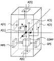
도 2는 본 발명에 의해 복수의 방향성 안테나로 구성되는 MS-SDMA 휴대용 이동 국의 개략적인 사시도.2 is a schematic perspective view of an MS-SDMA portable mobile station composed of a plurality of directional antennas according to the present invention;
도 3은 지구에 적용되는 고정 좌표계을 도시한 도면.3 shows a fixed coordinate system applied to the earth.
도 4는 본 발명에 의한 연산 방법에 해당하는 블럭도.Figure 4 is a block diagram corresponding to the calculation method according to the present invention.
도 5는 지구에 적용되는 고정 좌표계 내의 중력 및 자기장을 도시한 도면.5 shows gravity and magnetic fields in a fixed coordinate system applied to the earth.
도 6은 본 발명에 의해 한 통신 시스템 내에 통합된 카메라의 위치를 제어하기 위한 장치에 해당하는 블럭도.Fig. 6 is a block diagram corresponding to an apparatus for controlling the position of a camera integrated in one communication system by the present invention.
이러한 통신 시스템이 도 1에 묘사되어 있다. 이는 움직임(MOT)중 일 수 있는 적어도 하나의 제 2 무선국(SS) 및 제 1 무선국(PS)으로 구성된다. 제 2 무선국은 제 1 무선국과 통신하기 위한 적어도 하나의 제어 가능 구조(CS) 및 제 2 무선국의 운동에 따라 제어 가능 구조를 제어하기 위한 제어 수단(CONT)를 지닌다. 상기 제어 가능 구조(CS)의 제어 수단(CONT)은 지구 자기(H) 및 중력(G)장의 측정치를 제공하기 위한 자기장 센서(MFS) 및 중력장 센서(GFS)와, 예를 들면, 마이크로-제어기(micro-controller)일 수 있는, 연산 수단(COMP)으로 구성된다. 연산 수단은 각 센서로부터의 출력을 판독하며 제 2 무선국의 동태에 따라 적당한 시간 간격으로 제어 가능 구조를 제어하는데 필요한 계산을 한다.Such a communication system is depicted in FIG. 1. It consists of at least one second radio station (SS) and a first radio station (PS), which may be in motion (MOT). The second radio station has at least one controllable structure CS for communicating with the first radio station and control means CONT for controlling the controllable structure in accordance with the movement of the second radio station. The control means CONT of the controllable structure CS comprises a magnetic field sensor MFS and a gravity field sensor GFS for providing measurements of the earth's magnetic (H) and gravity (G) fields, for example a micro-controller. a computing means (COMP), which may be a micro-controller. The computing means reads the output from each sensor and makes the necessary calculations to control the controllable structure at appropriate time intervals in accordance with the dynamics of the second radio station.
바람직한 실시예에서, 자기장 및 중력장 센서는 3차원 센서이다. 바람직하게, 상기 3차원 자기장 센서는 3개의, 가급적 직교하며(orthogonal), 값이 싸며 매우 빠른 응답 시간을 가진 AMR(Anisotropic Magneto Resistive) 자기장 센서 소자를 사용하는 센서이다. 3차원적 중력장 센서는 또한 매우 값이 싼 구성 부품이며 빠른 응답 시간을 갖는 두 개의 제 2원적 중력장 센서 소자가 바람직하게 결합된 것이다.In a preferred embodiment, the magnetic and gravity field sensors are three-dimensional sensors. Preferably, the three-dimensional magnetic field sensor is a sensor that uses three, preferably orthogonal, inexpensive and very fast response times with AMR (Anisotropic Magneto Resistive) magnetic field sensor elements. The three-dimensional gravity field sensor is also a very inexpensive component and is preferably a combination of two secondary far-field sensor elements with fast response time.
바람직한 실시예에서, 통신 시스템은 MS-SDMA 통신 시스템이며, 여기서 제 1 무선국은 무선 기지국이며 제 2 무선국은 휴대용 이동 국이다. 휴대용 이동 국은 복수의 방향성 안테나를 포함하는 제어 가능 구조를 장착하고 있다. 도 2는, 예로서, 제어 가능 안테나 구조로서 여섯 개의 선택 가능 안테나 A[n](n=1 내지 6)를 도시하고 있다. 제어 가능 안테나 구조는 자기장 센서(MFS), 중력장 센서(GFS) 및 이들 센서에 의해 실행되는 측정치를 처리하는 연산 수단(COMP)에 의해 제어된다.In a preferred embodiment, the communication system is an MS-SDMA communication system, where the first radio station is a wireless base station and the second radio station is a portable mobile station. Portable mobile stations are equipped with a controllable structure comprising a plurality of directional antennas. 2 shows six selectable antennas A [n] (n = 1 to 6) as an example of a controllable antenna structure. The controllable antenna structure is controlled by magnetic field sensors (MFS), gravitational field sensors (GFS) and computing means (COMP) for processing the measurements carried out by these sensors.
다른 실시예에서, 제어 가능 구조는 위상 배열 안테나 시스템으로 구성된다. 이러한 제어 가능 안테나 구조는 오직 본 발명에 의한 통신 시스템에 대해 사용 가능하고, 10 GHz 보다 높은 주파수에서 동작한다. 가까운 미래에, 새로운 물질을 사용함으로써 약 몇 GHz의 라디오 주파수에 대한 이동 국을 가진 위상 배열 안테나의 집적 또한 가능케 할 수 있다.In another embodiment, the controllable structure consists of a phased array antenna system. This controllable antenna structure is only available for the communication system according to the present invention and operates at frequencies higher than 10 GHz. In the near future, the use of new materials may also enable the integration of phased array antennas with mobile stations for radio frequencies of about several GHz.
다음 부분은 바람직한 실시예에 해당하는 연산 방법을 설명한다. 상기 제어 가능 안테나 구조의 방사 방향들의 절대 측정치를 결정하기 위하여, 본 연산 방법은 제 2 무선국에 단단히(rigidly) 부착된 이동 3차원 좌표계(moving three-dimensional coordinate system)(이후, 국소 좌표계이라 불리움)에서 제어 가능 안테나 구조의 방사 방향을 한정하는 알려진 벡터 좌표를, 지구에 단단히 부착된 고정 3차원적 좌표계(이후, 전역 좌표계이라 불리움)에서 그 대응하는 좌표로 변환하기 위한 변환 단계를 포함하는 것을 필요로 한다. 이를 위해, 상기 연산 방법은 추후 한정될 지구 자기장, 복각 및 편각과 관련된 기준 각의 값 뿐 아니라 지구 자기장 및 지구 중력장의 3차원적 측정치를 사용한다.The following part describes the calculation method corresponding to the preferred embodiment. In order to determine an absolute measurement of the radial directions of the controllable antenna structure, the present computation method is a moving three-dimensional coordinate system (hereinafter referred to as local coordinate system) rigidly attached to the second radio station. It is necessary to include a transforming step for transforming a known vector coordinate that defines the radial direction of the controllable antenna structure from the fixed three-dimensional coordinate system (hereinafter referred to as the global coordinate system) firmly attached to the earth to its corresponding coordinate. Shall be. To this end, the calculation method uses three-dimensional measurements of the earth's magnetic field and the earth's gravitational field, as well as values of reference angles associated with the earth's magnetic field, dip and declination, which will be defined later.
국소 좌표는 단위 길이의 3개의 직교 벡터 (i,j,k)의 세트(도 2 참조)로 한정된다. 전역 좌표계은 단위 길이의 3개의 직교 벡터 (I,J,K)의 세트로 한정된다.I,J,K시스템은 도 3에 따라 한정된다.:Local coordinates are defined by a set of three orthogonal vectors (i, j, k ) of unit length (see FIG. 2). The global coordinate system is defined by a set of three orthogonal vectors (I, J, K ) of unit length.The I, J, K system is defined according to FIG.
-I는 지구 중력장(G) 방향과 일치한다.-I is consistent with the Earth's gravity field(G) direction.
-J는 지리적 북극(N) 방향과 일치한다.J coincides with the geographic north pole (N ) direction.
-K는 지리적 동극(E) 방향과 일치한다.K coincides with the geographic east (E ) direction.
복수의 방향성 안테나를 포함하는 제어 가능 구조의 경우에, 각 이동국 안테나는 헤딩(heading)이라 불리우는 최대 방사 방향으로써 특징지어진다. 안테나 A[n]을 생각해보면, 헤딩이 벡터r로 한정된다. 상기 국소 좌표계를 참조하면, 이 벡터는 다음과 같이 표현된다:In the case of a controllable structure comprising a plurality of directional antennas, each mobile station antenna is characterized by a maximum radiation direction called heading. Considering antenna A [n], the heading is defined by the vectorr . Referring to the local coordinate system, this vector is expressed as follows:

여기서 rx, ry및 rz는 파라메터로, 상기 이동국의 역학적 설계로부터 알려진다.Where rx , ry and rz are parameters, known from the mechanical design of the mobile station.
안테나 헤딩은 전역 좌표계에서 다음과 같이 표현된다:Antenna headings are represented in the global coordinate system as:

여기서 좌표 Rx,Ry 및 Rz는 알려져 있지 않다. 게다가, 이 값들은 상기 이동 국 및 지구의 상대 위치에 따라 변경된다.The coordinates Rx , Ry and Rz are not known here. In addition, these values change according to the relative positions of the mobile station and the earth.
도 4는 변환이 국소 좌표 (rx,ry,rz)가 전역 좌표 (Rx,Ry,Rz)로 되도록 하는 다양한 단계를 설명한다.4 illustrates various steps by which the transformation causes the local coordinates (rx , ry , rz ) to be global coordinates (Rx , Ry , Rz ).
* 적당한 시간 간격에서, 상기 연산 과정은 시작된다(ST).At a suitable time interval, the computation process starts (ST).
* 단계 S1 동안, 벡터r에 해당하는 국소 좌표 (rl)가 다운로드 된다. 이 값들은 각 이동 국 안테나 A[n]에 대한 표 안에 저장된다. 이 표에서, rx[n], ry[n], rz[n]은 상기 이동 국의 역학적 디자인에 의존하는 데이타이고, 동작 기간 중에 보통 변함이 없을 것이다. 따라서, 이것들은 예를 들면, 읽기 전용 기억 장치(ROM:Read Only Memory) 내에 저장된다.During step S1, local coordinates rl corresponding to the vectorr are downloaded. These values are stored in the table for each mobile station antenna A [n]. In this table, rx [n], ry [n], rz [n] are data that depends on the mechanical design of the mobile station and will normally remain unchanged during the operation period. Therefore, they are stored in, for example, a read only memory (ROM).
* 단계 S2 중에, 지구 자기장 H와 관련된 기준 각의 값들이 다운로드 된다. 이들 기준 각은 복각 및 편각이며 도 5에 의해 한정된다:During step S2, the values of the reference angles associated with the earth magnetic field H are downloaded. These reference angles are dip and declination and are defined by FIG. 5:
- 편각 (δ)은 지리적 북쪽 (N) 방향 및 지구 자기장H의, 수평 평면(HP)에서의 수평 투영인Hh 사이의 각도이다. 이 값은 동쪽(E)에서는 양(positive)으로 측정되며 0도 및 360도 사이에서 변한다.-Declination (δ) is the angle between the geographical north (N ) direction andHh , the horizontal projection in the horizontal plane (HP) of the earth's magnetic fieldH. This value is measured positive in the east (E ) and varies between 0 and 360 degrees.
- 복각(
복각 및 편각의 값은 지구 상에서 이동 국의 위치에 의존한다. 이 값들은 이동 국의 지리적 좌표에 기초하여 계산된다. 편각 및 복각은 또한 시간에 따라 변하는데, 소위 "영년 변화(secular variation)를 따른다. 전용 관측소에서 이 변화를 수세기 동안 측정해 왔다. 지난 500년 사이에 최악의 경우의 영년 변화는 10년 당 2도가 되고 있다. 현 이동 안테나의 지향성(directivity)이 본 수치 보다 더 넓다는 것을 고려해 본다면, 고정 값을 상기 통신 시스템의 성능에 심각한 결함을 주지 않고도, 편각 및 복각에 사용 가능하다.The values of dip and declination depend on the position of the mobile station on the earth. These values are calculated based on the geographic coordinates of the mobile station. The declination and dip also change over time, following the so-called “secular variation. Dedicated stations have measured this change for centuries. The worst-case perennial change over the last 500 years has been 2 per 10 years. Given that the directivity of the current mobile antenna is wider than this figure, fixed values can be used for declination and dip without seriously impairing the performance of the communication system.
본 발명에서, 이동 국의 위치에서 편각 및 복각의 값은 다른 방식으로 얻어질 수 있다:In the present invention, the values of declination and dip at the location of the mobile station can be obtained in different ways:
- 무선 기지국으로부터 수신함으로써. 무선 기지국은 그 위치의 편각 및 복각을 공통 다운링크 채널에 의해 송신할 수 있다. 이러한 타입의 채널은 대부분의 셀룰라 시스템에서 발견된다. 상기 무선 기지국에서의 편각 및 복각의 값이 상기 이동 국의 위치내의 것과 정확히 같지 않더라도, 그 차이는 이동 통신 셀의 정상 사이즈에 대해 대단히 작다.By receiving from a wireless base station. The wireless base station can transmit the declination and dip of that location by a common downlink channel. This type of channel is found in most cellular systems. Although the values of declination and dip at the wireless base station are not exactly the same as in the location of the mobile station, the difference is very small relative to the normal size of the mobile communication cell.
- 상기 이동 국의 지리적 좌표(위도/경도)의 함수로서 표현된 편각 및 복각의 장착된(on-board) 지리적 데이타 베이스를 판독함으로써, 상기 이동 국 좌표는 이동 통신 네트워크의 고정된 부분(예를 들어, 삼각법을 사용하여) 또는 온-보드 GPS 수신기로 제공된다.By reading an on-board geographic database of declinations and dips represented as a function of the geographic coordinates (latitude / longitude) of the mobile station, the mobile station coordinates being a fixed part of a mobile communication network (e.g. For example, using trigonometry) or an on-board GPS receiver.
- 이동 국의 지리적 좌표의 함수로서 편각 및 복각을 반환하는, 인터넷 지리적 데이타 베이스를 주기적으로 참조함으로써. 모든 제 2 및 제 3 세대 이동 네트워크 표준에 사용 가능한 라디오 패킷 서비스는 본 서비스를 빠르고, 믿을 수 있으며 저렴하게 제공할 수 있다.By periodically referencing the Internet geographical database, which returns declination and dip as a function of the geographical coordinates of the mobile station. Radio packet services available for all second and third generation mobile network standards can provide this service quickly, reliably and inexpensively.
상기 복각 및 편각의 값은 앞서 기술한 포착(acquisition) 모드에 따라, 어떤 타입의 메모리에도 저장될 수 있다. 바람직한 실시예에서, 이 메모리는 플래쉬(flash) 메모리이다.The dip and declination values may be stored in any type of memory, depending on the acquisition mode described above. In a preferred embodiment, this memory is a flash memory.
* 단계 S3 중에, 지구 자기장의 측정에 필요한 민감도(sensitivity) 및 정확도를 구비하고 이동 국에 연결된 자기 저항 센서(magneto-resistive field sensor)는 지구 자기장 H의 국소 좌표의 측정치를 제공한다. 지구 자기장은 국소 좌표계에서 다음과 같이 표현된다:During step S3, a magneto-resistive field sensor with the sensitivity and accuracy required for the measurement of the earth's magnetic field and connected to the mobile station provides a measure of the local coordinates of the earth's magnetic field H. The earth's magnetic field is expressed in the local coordinate system as follows:

다음으로, 지구 자기장의 방향은H와 같은 방향을 가지나 단위 길이인 벡터 h로 표현된다:Next, the direction of the earth's magnetic field is represented by the vector h, which has the same direction asH but in unit length:

여기서 H는 장의 세기이다.Where H is the strength of the field.
* 단계 S4 중에, 지구 중력장의 측정에 필요한 적당한 민감도 및 정확도를 가지며 이동 국에 연결된 중력장 센서는 지구 중력장G의 국소 좌표의 측정치를 제공한다. 지구 중력장은 다음과 같은 국소 좌표계으로 표현된다:During step S4, the gravitational field sensor connected to the mobile station with the appropriate sensitivity and accuracy necessary for the measurement of the gravitational field, provides a measure of the local coordinates of the gravitational fieldG. The earth's gravitational field is expressed in the local coordinate system:

지구 중력장의 방향은G와 방향은 같지만 단위 길이인 벡터g로 표현된다:The direction of the Earth's gravitational field is expressed as a vectorg in the same direction asG but in unit length:

여기서 G는 장의 세기이다.Where G is the strength of the field.
도 3에 의해,I는 단위 길이의 벡터로 지구 중력장과 방향이 일치한다. 이것은 정확히g의 정의(definition)이며, 수학식 6에 의해 표현된다. 따라서:3,I is a unit length vector that coincides with the Earth's gravitational field. This is exactly the definition ofg and is represented by equation (6). therefore:

벡터h는 두 번의 연속 회전에 의해J로 전달된다(carried over):Vectorh is carriered overJ by two consecutive rotations:
- 각도

- 각도
벡터 회전은 선형 변환이며, 3x3 행렬로 표현된다:Ri(u,


* 단계 S5 중에, 제 1 회전축에 해당하는 단위 길이 벡터e의 좌표는 다음과 같이 계산된다:During step S5, the coordinates of the unit length vectore corresponding to the first axis of rotation are calculated as follows:

e의 성분은 식 수학식 4와 수학식 7을 이용해서 유도된다:The components ofe are derived using equations (4) and (7):


단계 S6 중에, 제 1 회전은R1(e,

* 단계 S7 중에, 벡터hh는 다음과 같이 유도된다:During step S7, the vectorhh is derived as follows:

연산 후에, 다음과 같은 결과가 된다:After the operation, the result is:

여기서:here:


* 단계 S8 중에, 제 2 회전은R2(g,

* 단계 S9 중에, 벡터J는 다음과 같이 유도된다.During step S9, the vectorJ is derived as follows.

연산 후, 다음과 같이 된다.:After the operation, it looks like this:

여기서:here:


* 단계 S10 중에, 벡터K는 다음과 같이 얻어진다:During step S10, the vectorK is obtained as follows:

식 수학식 7과 수학식 20으로 주어진I 및J의 식을 사용하면:Using equationsI andJ given by equations (7) and (20):

* 단계 S11 중에서, 국소 좌표계 내의 벡터r의 식은 전역 좌표계 내의 같은 벡터의 수학식 2에서 유도되며,I, J및 K를 수학식 7, 수학식 20 및 수학식 25로 치환한다:In step S11, the expression of the vectorr in the local coordinate system is derived from

r에 대한 수학식 26을 고려하고 계수를 수학식 1의 계수와 같게 하면, 다음과 같이 된다:Considering equation 26 forr and making the coefficient equal to the coefficient in


알려지지 않은 Rx, Ry,Rz를 가지는 선형 시스템의 솔루션(solution)은 크레머 방법(Cramer's method)을 사용해 얻어지고, 전역 좌표계 내의 안테나의 헤딩을 정의하는 벡터의 좌표 (rg)를 제공한다.:The solution of a linear system with unknown Rx, Ry, Rz is obtained using the Cramer's method and provides the coordinates (rg) of the vector defining the heading of the antenna in the global coordinate system. :


여기서:here:


값 Rx[n], Ry[n], Rz[n]은 이동 국 위치에 의존한다. 이 값들은, 예를 들면, 임의 엑세스 메모리(RAM) 내에 저장될 수 있고 적당한 시간 간격에 이동 국의 동태에 따라 치환된다.The values Rx [n], Ry [n], Rz [n] depend on the mobile station position. These values may, for example, be stored in any access memory (RAM) and are substituted according to the dynamics of the mobile station at appropriate time intervals.
* 상기 연산의 마지막에서, 상기 절차는 시작점으로 돌아간다(RET).At the end of the operation, the procedure returns to the starting point (RET).
이 후, 상기 연산은 제어 가능 안테나 구조를 제어하는데 사용되며, 제어 가능 안테나 구조가 복수의 방향성 안테나로 구성되는 경우에 가장 최적의 안테나를 고르거나 위상 배열 안테나 시스템으로 구성되는 제어 가능 안테나 구조의 경우에 위상 배열 안테나를 재배열(realign)할 수 있고, 이 동작은 제 2 무선국의 동태와는 상관없이, 통신을 위한 최적의 조건을 제공하기 위해 실행된다. 이를 위해, 방향성 안테나 세트 내의 적절한 안테나 선택 또는 상기 위상 배열 안테나의 상기 재편성이 적당한 시간 간격으로, 기준 방향에 대해 실행되는데, 이는 바람직한 실시예에서 제 1 무선국 헤딩에 해당한다.Thereafter, the operation is used to control the controllable antenna structure, and in the case of the controllable antenna structure configured to select the most optimal antenna or to configure the phased array antenna system when the controllable antenna structure is composed of a plurality of directional antennas. It is possible to realign the phased array antennas in, and this operation is performed to provide optimum conditions for communication, regardless of the dynamics of the second radio station. To this end, the appropriate antenna selection in the directional antenna set or the realignment of the phased array antenna is performed in the reference direction, at appropriate time intervals, which in the preferred embodiment corresponds to the first radio station heading.
디. 핀크(D. Fink) 등이 쓴, 전자 엔지니어의 가이드 책, 4번째 판 (ISBN 0-07-021077-2)의 29.82 페이지, 29.3.1.1.1 섹션에서 이 기준 방향을 찾는 방법을 설명한다. 그 동작 원리는 단일 송신기 소스의 신호가 두 개의 알려진 지점 또는 소자에 수신된 단일 송신기 소스의 사용에 기초하고 있다. 운송 수단으로부터 상기 소스로의 방향은 상기 두 지점 또는 소자에서의 상기 신호의 차동 위상(differential phase)을 측정함으로써 결정된다.D. Page 29.82, page 29.3.1.1.1 of the Electronic Engineer's Guide, 4th edition (ISBN 0-07-021077-2), by D. Fink et al. Describes how to find this reference direction. The principle of operation is based on the use of a single transmitter source where a signal from a single transmitter source is received at two known points or elements. The direction from the vehicle to the source is determined by measuring the differential phase of the signal at the two points or elements.
무선 신호 방향을 찾는 다른 방법은 코닌클리즈케 필립스 일렉트로닉스 엔. 브이.(Koninklijke Philips Electronics N.V.)가 출원하고 아직 개시되지 않은, 유럽 특허 출원 번호 제 98 402738.3 호에 설명되어 있다. 이 방법은 예를 들면, 안테나 A[1] 및 A[2]에 의해 한정된 직교 좌표계(Cartesian system)로 무선 신호 RF의 도래각(angle of arrival)을 계산한다. 이어서, 상기 방법은 예를 들면 안테나 A[2] 및 A[3]에 의해 한정된 다른 직교 좌표계로 무선 신호 RF의 도래각을 계산한다. 상기 계산된 도래각을 사용해서, 3차원의 방위(bearing) 벡터가 계산되고, 이는 라디오 신호 RF의 소스를 가리키며 상기 기준 방향과 일치한다.Another way to find the direction of the wireless signal is Koninklizke Philips Electronics N. It is described in European Patent Application No. 98 402738.3, filed by Koninklijke Philips Electronics N.V. and not yet disclosed. This method calculates the angle of arrival of the radio signal RF, for example, in a Cartesian system defined by antennas A [1] and A [2]. The method then calculates the angle of arrival of the radio signal RF in another Cartesian coordinate system defined by antennas A [2] and A [3], for example. Using the calculated angle of arrival, a three-dimensional bearing vector is calculated, which points to the source of the radio signal RF and coincides with the reference direction.
이 방법으로 얻은 방위 벡터는 국소 좌표계 내에서 알려진다. 그 후, 방위 벡터는 앞서 설명된 변환 방법을 사용하여 전역 좌표계으로 변환된다. 방향성 안테나의 세트에서, 전역 좌표계 내의 상기 3차원 방위 벡터와 그 패턴이 가장 잘 대응하는 안테나{즉, 무선 신호 RF의 소스의 방향에서 최고치의 이득(gain)을 제공하는 안테나}가 선택된다.The orientation vector obtained in this way is known in the local coordinate system. The azimuth vector is then transformed into the global coordinate system using the transformation method described above. In the set of directional antennas, the antenna with which the three-dimensional orientation vector in the global coordinate system and its pattern best corresponds (ie, the antenna providing the highest gain in the direction of the source of the radio signal RF) is selected.
다른 방법을 사용하여 상기 방위 벡터를 얻을 수 있는데, 예를 들면 GPS 측정치에 기초한 방법이 있다.Another method can be used to obtain the azimuth vector, for example a method based on GPS measurements.
도 6은 본 발명에 의해 한 통신 시스템 내에 집적된 카메라의 위치를 제어하기 위한 장치 및 방법에 해당하는 제 2 실시예를 설명한다. 이는 더 구체적으로는 상기 카메라 서포트(support)의 동태와 관계없는 카메라 위치 설정 제어에 알맞다. 그러한 카메라는, 예를 들면, 이동 무선국 내에 집적될 수 있다.Figure 6 illustrates a second embodiment corresponding to an apparatus and method for controlling the position of a camera integrated in one communication system by the present invention. This is more particularly suitable for camera positioning control independent of the dynamics of the camera support. Such a camera may be integrated in a mobile radio station, for example.
카메라(CAM)는 그 서포트(support)에 대하여(relative to its support) 움직일 수 있으며, 서포트는 상기 이동 국 몸체(body)이며, 상기 이동 국이 상기 카메라 위치를 제어하기 위한 제어 수단을 구비한다. 다음의 동작은 카메라 위치를 제어하기 위해 실행된다.The camera CAM can move relative to its support, the support being the mobile station body, and the mobile station having control means for controlling the camera position. The following operation is performed to control the camera position.
초기화 단계 (REF) 중에, 전역 좌표계에 대해서 국소 좌표계의 초기 오일러 각도 {β1(0), β2(0), β3(0)}가 한정된다. 오일러 각도 (β1, β2, β3)는 3 회의 연속 회전으로 제 1 기준 시스템 (u1,u2,u3 )으로부터 제 2 기준 시스템 (v1,v2,v3 )까지 가는 것을 허용한다.:During the initialization step REF, the initial Euler angles {β1 (0), β2 (0), β3 (0)} of the local coordinate system are defined with respect to the global coordinate system. Euler angles (β1 , β2 , β3 ) go from the first reference system (u1 ,u2 ,u3 ) to the second reference system (v1 ,v2 ,v3 ) in three consecutive revolutions. Allow:
각도 β1으로,u1 둘레로의, 제 1 회전, Rot1(a first one, Rot1,aroundu1with an angle β1):To the angle β1,u1 round, the first rotating, Rot1 (a first one, Rot1,u1 around with an angle β1) :

각도 β2,u2 둘레의, 제 2 회전, Rot2(a second one, Rot2,aroundu2with an angle β2):Angle β2,u2 of the circumference, the second rotation, Rot2 (a second one, Rot2,u2 around with an angle β2) :

각도 β3,u3 둘레의, 3차 회전, Rot3(a third one, Rot3,aroundu3with an angle β3):Angles β3,u3 of the circumference, the third rotation, Rot3 (a third one, Rot3,u3 around with an angle β3) :

초기 각도는 상기 카메라가 유지되어야 하는 기준 위치에 해당하며, 예를 들면, 사용자에 의해 역학적으로 조정된다. 그 후, 다음의 단계가 규칙적으로 실행된다.The initial angle corresponds to the reference position at which the camera is to be maintained, for example dynamically adjusted by the user. After that, the following steps are executed regularly.
제 2 단계에서, 연산 수단 (CAL)은 3차원의 중력 및 자기장 센서(GFS 및 MFS)가 제공한 각각의 중력장(G) 및 자기장(H)의 측정치로부터 전역 좌표계을 먼저 결정한다. 제 2 실시예에서, 전역 좌표계은 다음의 직교 시스템 (u1,u2,u3)에 의해 한정된다. 여기서:In a second step, the computing means CAL first determines the global coordinate system from the measurements of the respective gravitational and magnetic fields H provided by the three-dimensional gravity and magnetic field sensors GFS and MFS. In the second embodiment, the global coordinate system is defined by the following orthogonal systemu1 ,u2 ,u3 . here:

결과적으로, 상기 연산 수단(CAL)은 전역 좌표계에 대해 상기 서포트에 적용되는 국소 좌표계의 현재 오일러 각도 {β1(t), β2(t), β3(t)}를 제공하는데, 여기서 t는 계산 시간이다.As a result, the computing means CAL provides the current Euler angles {β1 (t), β2 (t), β3 (t)} of the local coordinate system applied to the support relative to the global coordinate system, where t Is the calculation time.
제 3 단계에서, 정정(correction) 수단 (COR)은 초기 오일러 각도 및 현재 오일러 각도로부터 회전 {Δβ1(t), Δβ2(t), Δβ3(t)}을 연산하는데, 이것은 상기 카메라 서포트로 수행된다.:In a third step, the correction means (COR) calculates rotation {Δβ1 (t), Δβ2 (t), Δβ3 (t)} from the initial Euler angle and the current Euler angle, which is said camera support. Is performed as:
Δβi(t)=βi(t)-βi(0), i=1,2 또는 3Δβi (t) = βi (t) -βi (0), i = 1,2 or 3
마지막으로, 상기 제어 수단은 장치를 구동하는데, 예를 들면, 스텝 바이 스텝 모터(a step by step motor) (SSM)인데, 이 장치는 상기 카메라를 한정된 위치 내에 유지하기 위해 상기 정정 수단(COR)에 의해 연산된 회전 {-Δβ1(t), -Δβ2(t), -Δβ3(t)}를 실행한다.Finally, the control means drives an apparatus, for example a step by step motor (SSM), which is adapted to maintain the camera in a defined position. Rotation {-Δβ1 (t), -Δβ2 (t), and -Δβ3 (t)} calculated by
상기 카메라 위치 설정의 제어는 데이터 처리 수단(PROC)을 추가함으로써 향상시킬 수 있는데, 상기 수단은, 예를 들면, 카메라(CAM)가 제공한 일련의 화상(picture) 내 객체 인식 및 객체 운동 예측을 허용한다. 이를 위해, 상기 화상은 먼저 디지털화(digitized)된다. 화상 내의 객체의 인식은 불변량(invariants)의 검출에 기초를 두는데, 이것은 상기 객체의 파라미터가 되며, 푸리에 변환 또는 푸리에-멜린 변환을 이용한다. 상기 경우에 있어서, 불변량의 검출은 스케일링(scaling)과는 관계가 없다. 그리고 나서 동작 예측 수단을 이용하여 상기 객체의 운동에 대한 예측이 실행된다. 메모리의 비용의 이유로, 화상의 부표본화(sub-sampling)가 상기 데이터 처리 수단(PROC)이 적용되기 전에 실행될 수 있다.The control of the camera positioning can be improved by the addition of data processing means PROC, which means for example object recognition and object motion prediction in a series of pictures provided by the camera CAM. Allow. For this purpose, the picture is first digitized. Recognition of an object in an image is based on the detection of invariants, which becomes a parameter of the object and uses a Fourier transform or a Fourier-Melin transformation. In this case, the detection of the invariant has nothing to do with scaling. Prediction of the motion of the object is then performed using motion prediction means. For reasons of memory cost, sub-sampling of the image can be performed before the data processing means PROC is applied.
그 결과로서, 그러한 시스템이 예를 들면, 이미지(image) 처리 수단(PROC)이 제공한 동작 예측(p)을 사용하여 화상의 소자의 운동을 좇을 수 있다(follow the movement of an element). 이 경우, 정정 수단(COR)은 상기 스텝 바이 스텝 모터(SSM)에 의해 이루어지는 회전을 실행하는데, 상기 소자 동작으로 인한 각도를 카메라 서포트의 각도에 더함으로써 상기 소자가 운동할 때 카메라의 동작을 가능케 한다.As a result, such a system can follow the movement of an element of the image using, for example, motion prediction p provided by image processing means PROC. In this case, the correction means COR executes the rotation made by the step-by-step motor SSM, which enables the operation of the camera when the device moves by adding the angle resulting from the device operation to the angle of the camera support. do.
다른 데이터 처리 수단(PROC), 이를테면, 음성 인식 및 음성원(voice source)의 국소화(localization)를 위한 수단 역시 카메라가 상기 제어 수단에 의해 유지되어야 하는 기준 위치를 한정하기 위해 제공될 수 있다.Other data processing means (PROC), such as means for speech recognition and localization of voice sources, may also be provided to define the reference position at which the camera should be maintained by the control means.
Claims (12)
Translated fromKorean


Applications Claiming Priority (4)
| Application Number | Priority Date | Filing Date | Title |
|---|---|---|---|
| EP99400960.3 | 1999-04-20 | ||
| EP99400960 | 1999-04-20 | ||
| EP99402663 | 1999-10-26 | ||
| EP99402663.1 | 1999-10-26 |
Publications (2)
| Publication Number | Publication Date |
|---|---|
| KR20010053033A KR20010053033A (en) | 2001-06-25 |
| KR100707294B1true KR100707294B1 (en) | 2007-04-16 |
Family
ID=26153654
Family Applications (1)
| Application Number | Title | Priority Date | Filing Date |
|---|---|---|---|
| KR1020007014452AExpired - Fee RelatedKR100707294B1 (en) | 1999-04-20 | 2000-04-12 | Communication systems and radio stations, methods of controlling controllable structures and computational methods for using such communication systems |
Country Status (7)
| Country | Link |
|---|---|
| US (1) | US6850737B1 (en) |
| EP (1) | EP1090440B1 (en) |
| JP (1) | JP4450517B2 (en) |
| KR (1) | KR100707294B1 (en) |
| CN (1) | CN1248362C (en) |
| DE (1) | DE60039277D1 (en) |
| WO (1) | WO2000064006A1 (en) |
Families Citing this family (13)
| Publication number | Priority date | Publication date | Assignee | Title |
|---|---|---|---|---|
| US7003083B2 (en)* | 2001-02-13 | 2006-02-21 | International Business Machines Corporation | Selectable audio and mixed background sound for voice messaging system |
| EP1249890A1 (en)* | 2001-04-09 | 2002-10-16 | TDK Corporation | Broadcasting receiving apparatus with a geomagnetic sensor to control the directivity of the antenna |
| US20030162519A1 (en)* | 2002-02-26 | 2003-08-28 | Martin Smith | Radio communications device |
| US20040004951A1 (en)* | 2002-07-05 | 2004-01-08 | Interdigital Technology Corporation | Method for performing wireless switching |
| EP1562257A1 (en)* | 2004-02-06 | 2005-08-10 | Sony International (Europe) GmbH | Antenna motion tracking for short range wireless mobile communication system |
| US7346336B2 (en)* | 2004-08-10 | 2008-03-18 | Gerald Kampel | Personal activity sensor and locator device |
| JP2006094368A (en)* | 2004-09-27 | 2006-04-06 | Nec Corp | Mobile phone, azimuth detection method of mobile phone, and mobile phone system |
| EP1646112A1 (en)* | 2004-10-11 | 2006-04-12 | Sony Deutschland GmbH | Directivity control for short range wireless mobile communication systems |
| JP2006197418A (en)* | 2005-01-17 | 2006-07-27 | Sharp Corp | Mobile communication terminal and communication sensitivity adjustment method |
| US9147935B2 (en)* | 2011-08-10 | 2015-09-29 | Qualcomm Incorporated | Maintenance of mobile device RF beam |
| CN103267961B (en)* | 2013-04-23 | 2016-07-06 | 中国科学技术大学 | The direction-finding method of a kind of mobile terminal, system and this mobile terminal |
| CN103607493B (en)* | 2013-11-29 | 2016-03-23 | 哈尔滨工业大学 | The correction for direction method of smart mobile phone |
| KR101925570B1 (en) | 2017-10-20 | 2018-12-06 | 국방과학연구소 | Method and apparatus for providing target tracing in antenna system |
Citations (3)
| Publication number | Priority date | Publication date | Assignee | Title |
|---|---|---|---|---|
| JPH02148902A (en)* | 1988-11-30 | 1990-06-07 | Hitachi Ltd | antenna direction adjustment device |
| JPH0579849A (en)* | 1991-09-20 | 1993-03-30 | Fujitsu Ten Ltd | Avm system |
| WO1998029968A2 (en)* | 1996-12-30 | 1998-07-09 | At & T Corp. | Portable satellite phone for communication with direct link to satellite |
Family Cites Families (13)
| Publication number | Priority date | Publication date | Assignee | Title |
|---|---|---|---|---|
| US3680124A (en)* | 1964-05-11 | 1972-07-25 | Us Navy | System for determining azimuth |
| JPS615601A (en)* | 1984-06-20 | 1986-01-11 | Nec Corp | Antenna tracking device |
| EP0432647B1 (en)* | 1989-12-11 | 1995-06-21 | Kabushiki Kaisha Toyota Chuo Kenkyusho | Mobile antenna system |
| US5419521A (en)* | 1993-04-15 | 1995-05-30 | Matthews; Robert J. | Three-axis pedestal |
| US5446465A (en)* | 1993-06-18 | 1995-08-29 | Diefes; Debra L. | Satellite location and pointing system for use with global positioning system |
| US5471218A (en)* | 1993-07-01 | 1995-11-28 | Trimble Navigation Limited | Integrated terrestrial survey and satellite positioning system |
| JPH10126135A (en)* | 1994-09-09 | 1998-05-15 | Software Sekkei:Kk | Direction measurement method and direction measurement device for beam antenna and direction controller for antenna |
| US5948044A (en)* | 1996-05-20 | 1999-09-07 | Harris Corporation | Hybrid GPS/inertially aided platform stabilization system |
| EP0886425A1 (en)* | 1997-06-23 | 1998-12-23 | Gérard Peudepiece | Portable emergency call system for mobile radio |
| CA2307877C (en)* | 1997-10-30 | 2005-08-30 | The Microoptical Corporation | Eyeglass interface system |
| US6065219A (en)* | 1998-06-26 | 2000-05-23 | Dresser Industries, Inc. | Method and apparatus for determining the shape of an earth borehole and the motion of a tool within the borehole |
| US6150977A (en)* | 1998-10-30 | 2000-11-21 | Trw Inc. | Method for enhancing the performance of a satellite communications system using multibeam antennas |
| US6016120A (en)* | 1998-12-17 | 2000-01-18 | Trimble Navigation Limited | Method and apparatus for automatically aiming an antenna to a distant location |
- 2000
- 2000-04-12KRKR1020007014452Apatent/KR100707294B1/ennot_activeExpired - Fee Related
- 2000-04-12CNCNB008010595Apatent/CN1248362C/ennot_activeExpired - Fee Related
- 2000-04-12DEDE60039277Tpatent/DE60039277D1/ennot_activeExpired - Lifetime
- 2000-04-12WOPCT/EP2000/003268patent/WO2000064006A1/enactiveIP Right Grant
- 2000-04-12EPEP00917079Apatent/EP1090440B1/ennot_activeExpired - Lifetime
- 2000-04-12JPJP2000613036Apatent/JP4450517B2/ennot_activeExpired - Fee Related
- 2000-04-18USUS09/551,011patent/US6850737B1/ennot_activeExpired - Lifetime
Patent Citations (3)
| Publication number | Priority date | Publication date | Assignee | Title |
|---|---|---|---|---|
| JPH02148902A (en)* | 1988-11-30 | 1990-06-07 | Hitachi Ltd | antenna direction adjustment device |
| JPH0579849A (en)* | 1991-09-20 | 1993-03-30 | Fujitsu Ten Ltd | Avm system |
| WO1998029968A2 (en)* | 1996-12-30 | 1998-07-09 | At & T Corp. | Portable satellite phone for communication with direct link to satellite |
Also Published As
| Publication number | Publication date |
|---|---|
| WO2000064006A1 (en) | 2000-10-26 |
| JP2002542696A (en) | 2002-12-10 |
| KR20010053033A (en) | 2001-06-25 |
| CN1314015A (en) | 2001-09-19 |
| EP1090440A1 (en) | 2001-04-11 |
| EP1090440B1 (en) | 2008-06-25 |
| CN1248362C (en) | 2006-03-29 |
| US6850737B1 (en) | 2005-02-01 |
| DE60039277D1 (en) | 2008-08-07 |
| JP4450517B2 (en) | 2010-04-14 |
Similar Documents
| Publication | Publication Date | Title |
|---|---|---|
| CN109425365B (en) | Method, device and equipment for calibrating laser scanning equipment and storage medium | |
| KR100707294B1 (en) | Communication systems and radio stations, methods of controlling controllable structures and computational methods for using such communication systems | |
| US6377211B1 (en) | Apparatus and method for pointing a directional device from a moving vehicle toward a spacecraft | |
| KR101809294B1 (en) | Method and system of determining spatial orientation information of a body from multiple electromagnetic signals | |
| WO2023207110A1 (en) | Satellite navigation anti-deception method and system based on integrated navigation and using array antenna | |
| CN108493611B (en) | Device, method and system for rapidly aligning communication-in-motion antenna and communication satellite | |
| EP1795864A1 (en) | Magnetic sensor control method, magnetic sensor controller and portable terminal device | |
| KR20170082016A (en) | Method and apparatus for estimating position in terminal | |
| JP3589990B2 (en) | Antenna control method and antenna control device | |
| KR20020030244A (en) | A three-axis magnetic sensor, an omnidirectional magnetic sensor and an azimuth measureing method using the same | |
| KR20060050321A (en) | Bearing data generation method, bearing sensor unit and portable electronic device | |
| CN108886392B (en) | Antenna selection method and electronic device | |
| CN111148020A (en) | Positioning system, method, device and computer readable storage medium | |
| KR102747497B1 (en) | Phase center compensation for high-precision GNSS antennas | |
| US9217639B1 (en) | North-finding using inertial navigation system | |
| JP4019149B2 (en) | Radio wave arrival direction identification system | |
| CN107248891B (en) | Direction and gesture measuring device for mobile communication antenna pointing monitoring | |
| WO2025064119A1 (en) | Location of target object using 2-antenna aoa, wireless ranging, and user equipment orientations | |
| WO2018011810A1 (en) | Imaging system and method for accurately directing antennas | |
| JP2006023293A (en) | Portable electronic apparatus with azimuth detecting function and calibration method therefor, and method and device for measuring offset of magnetic sensor | |
| US6735524B1 (en) | Spatially resolved and spatially aware antenna for radio navigation | |
| US20240253829A1 (en) | Radio ranging for gps-denied landing of unmanned aircraft | |
| Tan et al. | Multi-Sensor Based IoT Indoor Localization | |
| JP2024131897A (en) | Attitude and orientation estimation device, satellite communication earth station, and attitude and orientation estimation method | |
| WO2024236887A1 (en) | Positioning system |
Legal Events
| Date | Code | Title | Description |
|---|---|---|---|
| PA0105 | International application | St.27 status event code:A-0-1-A10-A15-nap-PA0105 | |
| PG1501 | Laying open of application | St.27 status event code:A-1-1-Q10-Q12-nap-PG1501 | |
| A201 | Request for examination | ||
| P11-X000 | Amendment of application requested | St.27 status event code:A-2-2-P10-P11-nap-X000 | |
| P13-X000 | Application amended | St.27 status event code:A-2-2-P10-P13-nap-X000 | |
| PA0201 | Request for examination | St.27 status event code:A-1-2-D10-D11-exm-PA0201 | |
| E902 | Notification of reason for refusal | ||
| PE0902 | Notice of grounds for rejection | St.27 status event code:A-1-2-D10-D21-exm-PE0902 | |
| P11-X000 | Amendment of application requested | St.27 status event code:A-2-2-P10-P11-nap-X000 | |
| P13-X000 | Application amended | St.27 status event code:A-2-2-P10-P13-nap-X000 | |
| E701 | Decision to grant or registration of patent right | ||
| PE0701 | Decision of registration | St.27 status event code:A-1-2-D10-D22-exm-PE0701 | |
| GRNT | Written decision to grant | ||
| PR0701 | Registration of establishment | St.27 status event code:A-2-4-F10-F11-exm-PR0701 | |
| PR1002 | Payment of registration fee | St.27 status event code:A-2-2-U10-U12-oth-PR1002 Fee payment year number:1 | |
| PG1601 | Publication of registration | St.27 status event code:A-4-4-Q10-Q13-nap-PG1601 | |
| R17-X000 | Change to representative recorded | St.27 status event code:A-5-5-R10-R17-oth-X000 | |
| PN2301 | Change of applicant | St.27 status event code:A-5-5-R10-R11-asn-PN2301 | |
| PN2301 | Change of applicant | St.27 status event code:A-5-5-R10-R14-asn-PN2301 | |
| PR1001 | Payment of annual fee | St.27 status event code:A-4-4-U10-U11-oth-PR1001 Fee payment year number:4 | |
| PR1001 | Payment of annual fee | St.27 status event code:A-4-4-U10-U11-oth-PR1001 Fee payment year number:5 | |
| FPAY | Annual fee payment | ||
| PR1001 | Payment of annual fee | St.27 status event code:A-4-4-U10-U11-oth-PR1001 Fee payment year number:6 | |
| FPAY | Annual fee payment | ||
| PR1001 | Payment of annual fee | St.27 status event code:A-4-4-U10-U11-oth-PR1001 Fee payment year number:7 | |
| R18-X000 | Changes to party contact information recorded | St.27 status event code:A-5-5-R10-R18-oth-X000 | |
| PN2301 | Change of applicant | St.27 status event code:A-5-5-R10-R13-asn-PN2301 St.27 status event code:A-5-5-R10-R11-asn-PN2301 | |
| PR1001 | Payment of annual fee | St.27 status event code:A-4-4-U10-U11-oth-PR1001 Fee payment year number:8 | |
| PR1001 | Payment of annual fee | St.27 status event code:A-4-4-U10-U11-oth-PR1001 Fee payment year number:9 | |
| PR1001 | Payment of annual fee | St.27 status event code:A-4-4-U10-U11-oth-PR1001 Fee payment year number:10 | |
| PR1001 | Payment of annual fee | St.27 status event code:A-4-4-U10-U11-oth-PR1001 Fee payment year number:11 | |
| LAPS | Lapse due to unpaid annual fee | ||
| PC1903 | Unpaid annual fee | St.27 status event code:A-4-4-U10-U13-oth-PC1903 Not in force date:20180407 Payment event data comment text:Termination Category : DEFAULT_OF_REGISTRATION_FEE | |
| PC1903 | Unpaid annual fee | St.27 status event code:N-4-6-H10-H13-oth-PC1903 Ip right cessation event data comment text:Termination Category : DEFAULT_OF_REGISTRATION_FEE Not in force date:20180407 | |
| R18-X000 | Changes to party contact information recorded | St.27 status event code:A-5-5-R10-R18-oth-X000 | |
| R18-X000 | Changes to party contact information recorded | St.27 status event code:A-5-5-R10-R18-oth-X000 | |
| R18-X000 | Changes to party contact information recorded | St.27 status event code:A-5-5-R10-R18-oth-X000 |