KR100706790B1 - Oxidation treatment apparatus and method - Google Patents
Oxidation treatment apparatus and methodDownload PDFInfo
- Publication number
- KR100706790B1 KR100706790B1KR1020050116482AKR20050116482AKR100706790B1KR 100706790 B1KR100706790 B1KR 100706790B1KR 1020050116482 AKR1020050116482 AKR 1020050116482AKR 20050116482 AKR20050116482 AKR 20050116482AKR 100706790 B1KR100706790 B1KR 100706790B1
- Authority
- KR
- South Korea
- Prior art keywords
- ozone
- processing chamber
- chamber
- load lock
- boat
- Prior art date
- Legal status (The legal status is an assumption and is not a legal conclusion. Google has not performed a legal analysis and makes no representation as to the accuracy of the status listed.)
- Expired - Fee Related
Links
Images


Classifications
- H—ELECTRICITY
- H01—ELECTRIC ELEMENTS
- H01L—SEMICONDUCTOR DEVICES NOT COVERED BY CLASS H10
- H01L21/00—Processes or apparatus adapted for the manufacture or treatment of semiconductor or solid state devices or of parts thereof
- H01L21/02—Manufacture or treatment of semiconductor devices or of parts thereof
- H01L21/02104—Forming layers
- H01L21/02107—Forming insulating materials on a substrate
- H01L21/02225—Forming insulating materials on a substrate characterised by the process for the formation of the insulating layer
- H01L21/02227—Forming insulating materials on a substrate characterised by the process for the formation of the insulating layer formation by a process other than a deposition process
- H01L21/0223—Forming insulating materials on a substrate characterised by the process for the formation of the insulating layer formation by a process other than a deposition process formation by oxidation, e.g. oxidation of the substrate
- H01L21/02233—Forming insulating materials on a substrate characterised by the process for the formation of the insulating layer formation by a process other than a deposition process formation by oxidation, e.g. oxidation of the substrate of the semiconductor substrate or a semiconductor layer
- H—ELECTRICITY
- H01—ELECTRIC ELEMENTS
- H01L—SEMICONDUCTOR DEVICES NOT COVERED BY CLASS H10
- H01L21/00—Processes or apparatus adapted for the manufacture or treatment of semiconductor or solid state devices or of parts thereof
- H01L21/67—Apparatus specially adapted for handling semiconductor or electric solid state devices during manufacture or treatment thereof; Apparatus specially adapted for handling wafers during manufacture or treatment of semiconductor or electric solid state devices or components ; Apparatus not specifically provided for elsewhere
- H01L21/67005—Apparatus not specifically provided for elsewhere
- H01L21/67011—Apparatus for manufacture or treatment
- H01L21/67017—Apparatus for fluid treatment
- H—ELECTRICITY
- H01—ELECTRIC ELEMENTS
- H01L—SEMICONDUCTOR DEVICES NOT COVERED BY CLASS H10
- H01L21/00—Processes or apparatus adapted for the manufacture or treatment of semiconductor or solid state devices or of parts thereof
- H01L21/02—Manufacture or treatment of semiconductor devices or of parts thereof
- H01L21/02104—Forming layers
- H01L21/02107—Forming insulating materials on a substrate
- H01L21/02296—Forming insulating materials on a substrate characterised by the treatment performed before or after the formation of the layer
- H01L21/02299—Forming insulating materials on a substrate characterised by the treatment performed before or after the formation of the layer pre-treatment
- H01L21/02312—Forming insulating materials on a substrate characterised by the treatment performed before or after the formation of the layer pre-treatment treatment by exposure to a gas or vapour
- H—ELECTRICITY
- H01—ELECTRIC ELEMENTS
- H01L—SEMICONDUCTOR DEVICES NOT COVERED BY CLASS H10
- H01L21/00—Processes or apparatus adapted for the manufacture or treatment of semiconductor or solid state devices or of parts thereof
- H01L21/02—Manufacture or treatment of semiconductor devices or of parts thereof
- H01L21/04—Manufacture or treatment of semiconductor devices or of parts thereof the devices having potential barriers, e.g. a PN junction, depletion layer or carrier concentration layer
- H01L21/50—Assembly of semiconductor devices using processes or apparatus not provided for in a single one of the groups H01L21/18 - H01L21/326 or H10D48/04 - H10D48/07 e.g. sealing of a cap to a base of a container
- H01L21/56—Encapsulations, e.g. encapsulation layers, coatings
- H—ELECTRICITY
- H01—ELECTRIC ELEMENTS
- H01L—SEMICONDUCTOR DEVICES NOT COVERED BY CLASS H10
- H01L21/00—Processes or apparatus adapted for the manufacture or treatment of semiconductor or solid state devices or of parts thereof
- H01L21/67—Apparatus specially adapted for handling semiconductor or electric solid state devices during manufacture or treatment thereof; Apparatus specially adapted for handling wafers during manufacture or treatment of semiconductor or electric solid state devices or components ; Apparatus not specifically provided for elsewhere
- H01L21/67005—Apparatus not specifically provided for elsewhere
- H01L21/67011—Apparatus for manufacture or treatment
- H01L21/67098—Apparatus for thermal treatment
- H—ELECTRICITY
- H01—ELECTRIC ELEMENTS
- H01L—SEMICONDUCTOR DEVICES NOT COVERED BY CLASS H10
- H01L21/00—Processes or apparatus adapted for the manufacture or treatment of semiconductor or solid state devices or of parts thereof
- H01L21/67—Apparatus specially adapted for handling semiconductor or electric solid state devices during manufacture or treatment thereof; Apparatus specially adapted for handling wafers during manufacture or treatment of semiconductor or electric solid state devices or components ; Apparatus not specifically provided for elsewhere
- H01L21/67005—Apparatus not specifically provided for elsewhere
- H01L21/67011—Apparatus for manufacture or treatment
- H01L21/67155—Apparatus for manufacturing or treating in a plurality of work-stations
- H01L21/67201—Apparatus for manufacturing or treating in a plurality of work-stations characterized by the construction of the load-lock chamber
- H—ELECTRICITY
- H01—ELECTRIC ELEMENTS
- H01L—SEMICONDUCTOR DEVICES NOT COVERED BY CLASS H10
- H01L21/00—Processes or apparatus adapted for the manufacture or treatment of semiconductor or solid state devices or of parts thereof
- H01L21/67—Apparatus specially adapted for handling semiconductor or electric solid state devices during manufacture or treatment thereof; Apparatus specially adapted for handling wafers during manufacture or treatment of semiconductor or electric solid state devices or components ; Apparatus not specifically provided for elsewhere
- H01L21/67005—Apparatus not specifically provided for elsewhere
- H01L21/67242—Apparatus for monitoring, sorting or marking
- H01L21/67248—Temperature monitoring
- H—ELECTRICITY
- H01—ELECTRIC ELEMENTS
- H01L—SEMICONDUCTOR DEVICES NOT COVERED BY CLASS H10
- H01L21/00—Processes or apparatus adapted for the manufacture or treatment of semiconductor or solid state devices or of parts thereof
- H01L21/67—Apparatus specially adapted for handling semiconductor or electric solid state devices during manufacture or treatment thereof; Apparatus specially adapted for handling wafers during manufacture or treatment of semiconductor or electric solid state devices or components ; Apparatus not specifically provided for elsewhere
- H01L21/683—Apparatus specially adapted for handling semiconductor or electric solid state devices during manufacture or treatment thereof; Apparatus specially adapted for handling wafers during manufacture or treatment of semiconductor or electric solid state devices or components ; Apparatus not specifically provided for elsewhere for supporting or gripping
Landscapes
- Engineering & Computer Science (AREA)
- Physics & Mathematics (AREA)
- Condensed Matter Physics & Semiconductors (AREA)
- General Physics & Mathematics (AREA)
- Manufacturing & Machinery (AREA)
- Computer Hardware Design (AREA)
- Microelectronics & Electronic Packaging (AREA)
- Power Engineering (AREA)
Abstract
Translated fromKoreanDescription
Translated fromKorean도 1은 본 발명의 산화 처리 장치의 일 예를 보여주는 도면;1 shows an example of an oxidation treatment apparatus of the present invention;
도 2는 오존 분사 노즐의 내부를 보여주기 위해 일부분을 절단한 사시도;2 is a perspective view of a portion cut away to show the interior of the ozone injection nozzle;
도 3은 도 1의 제 1 오존 공급 유닛의 종단면도;3 is a longitudinal sectional view of the first ozone supply unit of FIG. 1;
도 4는 도 3에서 선 Ⅰ-Ⅰ을 따라 절단한 제 1 오존 분사 노즐과 냉각 부재의 횡단면도;4 is a cross-sectional view of the first ozone jet nozzle and the cooling member taken along the line I-I in FIG. 3;
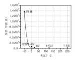
도 5는 온도에 따른 오존의 수명을 보여주는 도면;5 shows the life of ozone with temperature;
도 6은 도 3의 분리판의 사시도;6 is a perspective view of the separator of FIG. 3;
도 7은 오존 분사 노즐과 냉각관에서 오존과 냉각 유체가 흐르는 경로를 보여주는 도면;7 is a view illustrating a path through which ozone and a cooling fluid flow in an ozone injection nozzle and a cooling tube;
도 8은 본 발명의 산화 처리 장치의 다른 예를 보여주는 도면;8 shows another example of the oxidation treatment apparatus of the present invention;
도 9는 본 발명의 산화 처리 장치의 또 다른 예를 보여주는 도면;9 shows another example of the oxidation treatment apparatus of the present invention;
도 10은 도 9의 제 2 오존 공급 유닛의 구조를 개략적으로 보여주는 도면; 그리고FIG. 10 schematically shows the structure of the second ozone supply unit of FIG. 9; FIG. And
도 11은 산화 처리 장치의 또 다른 예를 보여주는 도면이다.11 is a view showing still another example of the oxidation treatment apparatus.
* 도면의 주요 부분에 대한 부호의 설명 *Explanation of symbols on the main parts of the drawings
100 : 처리실 120 : 공정 튜브100: process chamber 120: process tube
140 : 플랜지 200 : 로드록 챔버140: flange 200: load lock chamber
300 : 보트 400 : 제 1 오존 공급 유닛300: boat 400: first ozone supply unit
420 : 오존 발생기 440 : 오존 분사 노즐420: ozone generator 440: ozone injection nozzle
460 : 냉각 부재 464 : 냉각관460: cooling member 464: cooling tube
490 : 분리판 500 : 제 2 오존 공급 유닛490: separator 500: second ozone supply unit
600 : 제거 가스 공급 부재600: removal gas supply member
본 발명은 반도체 소자를 제조하는 장치 및 방법에 관한 것으로, 더 상세하게는 반도체 기판을 산화 처리하는 장치 및 방법에 관한 것이다.The present invention relates to an apparatus and method for manufacturing a semiconductor device, and more particularly, to an apparatus and method for oxidizing a semiconductor substrate.
반도체 소자를 제조하기 위해 반도체 웨이퍼와 같은 기판 상에 다양한 공정들이 수행된다. 이들 공정들 중 산화 공정은 웨이퍼 상에 산소(O)를 공급하여 산화막을 형성하는 공정이다. 일반적으로 사용되는 산화 공정에 의하면 처리실 내에 복수매의 웨이퍼들이 적재된 보트를 위치시키고 그 내부로 반응가스로서 산소(O2)와 수소(H2)를 주입하여 산화 공정을 수행하였다. 그러나 이 경우, 수소(H)가 산화막 내에 함입되어 산화막의 신뢰성을 저하시킨다. 특히, 산화 공정이 플래시 메모리에서 전하가 터널링되는 터널 산화막(tunnel oxidation layer)을 형성하는 공정인 경우, 산화막에 합입된 수소(H)가 비록 소량이라 할지라도 터널 산화막의 신뢰성을 크게 저하시킨다.Various processes are performed on a substrate, such as a semiconductor wafer, to manufacture a semiconductor device. Among these processes, an oxidation process is a process of forming an oxide film by supplying oxygen (O) on a wafer. In general, the oxidation process is performed by placing a boat loaded with a plurality of wafers in a processing chamber and injecting oxygen (O2 ) and hydrogen (H2 ) as reaction gas into the boat. In this case, however, hydrogen (H) is embedded in the oxide film, thereby lowering the reliability of the oxide film. In particular, when the oxidation process is a process of forming a tunnel oxide layer in which charge is tunneled in the flash memory, even if a small amount of hydrogen (H) incorporated into the oxide film, the reliability of the tunnel oxide film is greatly reduced.
또한, 처리실 내로 수소(H2)와 산소(O2)를 공급하여 산화 공정을 진행하는 경우, 이들을 반응하여 산소(O)를 발생시키기 위해서는 처리실 내부가 고온으로 유지되어야 하므로 20 내지 30Å 두께의 얇은 산화막을 형성하기 어렵다.In addition, when the oxidation process is performed by supplying hydrogen (H2 ) and oxygen (O2 ) into the process chamber, the inside of the process chamber must be maintained at a high temperature so as to generate oxygen (O) by reacting them. It is difficult to form an oxide film.
또한, 웨이퍼들이 처리실로 유입되기 전 웨이퍼 표면에 잔류하는 탄화수소(hydrocarbon)로 인해 산화 공정 진행시 웨이퍼 상에 양질의 산화막을 형성하기 어렵다.In addition, it is difficult to form a high quality oxide film on the wafer during the oxidation process due to hydrocarbons remaining on the wafer surface before the wafers are introduced into the process chamber.
또한, 일반적으로 처리실 내에는 다양한 금속 구조물들이 제공된다. 공정 진행 중 이들 금속 구조물로부터 발생하는 나트륨, 철, 망간 등과 같은 금속 파티클들이 웨이퍼에 흡착되어 공정 불량을 유발한다.Also, various metal structures are generally provided within the process chamber. Metal particles, such as sodium, iron, and manganese, generated from these metal structures during the process are adsorbed onto the wafer, causing process defects.
본 발명은 반도체 기판 상에 양질의 산화막을 형성할 수 있는 산화 처리 장치 및 방법을 제공하는 것을 목적으로 한다.An object of the present invention is to provide an oxidation treatment apparatus and method capable of forming a high quality oxide film on a semiconductor substrate.
또한, 본 발명은 산화 공정에 의해 웨이퍼 상에 산화막을 형성할 때, 산화막 내에 수소가 함입되는 것을 최소화할 수 있는 산화 처리 장치 및 방법을 제공하는 것을 목적으로 한다.In addition, an object of the present invention is to provide an oxidation treatment apparatus and method capable of minimizing the incorporation of hydrogen into an oxide film when forming an oxide film on the wafer by an oxidation process.
또한, 본 발명은 공정 진행시 처리실 내 금속 파티클을 제거하여 웨이퍼 상에 양질의 산화막을 형성할 수 있는 산화 처리 장치 및 방법을 제공하는 것을 목적으로 한다.In addition, an object of the present invention is to provide an oxidation treatment apparatus and method capable of forming a high quality oxide film on a wafer by removing metal particles in the processing chamber during the process.
또한, 본 발명은 산화 공정 진행 전에 반도체 기판 상에 잔류하는 탄화수소를 제거하여 반도체 기판 상에 양질의 산화막을 형성할 수 있는 산화 처리 장치 및 방법을 제공하는 것을 목적으로 한다.In addition, an object of the present invention is to provide an oxidation treatment apparatus and method capable of forming a high quality oxide film on a semiconductor substrate by removing hydrocarbons remaining on the semiconductor substrate before the oxidation process.
본 발명은 산화 공정을 수행하는 장치를 제공한다. 본 발명의 일 특징에 의하면, 상기 장치는 공정이 수행되는 공간을 제공하며 공정 진행시 가열 부재에 의해 공정 온도로 가열되는 처리실, 공정 진행시 상기 처리실 내에 위치되며 기판을 지지하는 보트, 그리고 상기 처리실 내로 오존 가스를 공급하는 제 1 오존 공급 유닛을 포함한다. 상기 제 1 오존 공급 유닛은 상기 처리실 외부에 배치되며 오존을 발생시키는 오존 발생기와 상기 처리실 내에 배치되며 상기 오존 발생기로부터 공급받은 오존을 상기 처리실 내로 분사하는 오존 분사 노즐을 포함한다. 일 예에 의하면, 상기 보트에는 상기 기판들이 상하로 적층되며, 상기 오존 분사 노즐은 상하방향으로 수직하게 배치되고, 상기 오존 분사 노즐에는 그 길이 방향을 따라 복수의 분사구들이 형성될 수 있다.The present invention provides an apparatus for carrying out an oxidation process. According to one aspect of the invention, the apparatus provides a space in which the process is performed and the process chamber is heated to the process temperature by the heating member during the process, the boat located in the process chamber and supporting the substrate during the process, and the process chamber A first ozone supply unit for supplying ozone gas into the chamber. The first ozone supply unit includes an ozone generator disposed outside the treatment chamber and generating ozone, and an ozone injection nozzle disposed in the treatment chamber and injecting ozone supplied from the ozone generator into the treatment chamber. According to an example, the substrates may be stacked up and down in the boat, and the ozone spray nozzle may be vertically disposed in the vertical direction, and a plurality of spray holes may be formed in the ozone spray nozzle in the longitudinal direction thereof.
본 발명의 다른 특징에 의하면, 상기 제 1 오존 공급 유닛은 상기 오존 분사 노즐 내로 공급된 오존을 냉각하는 냉각 부재를 더 포함한다. 일 예에 의하면, 상기 냉각 부재는 상기 오존 분사 노즐을 감싸도록 배치되며 냉각 유체가 흐르는 냉각관을 포함한다. 또한, 상기 냉각관 내에는 상기 냉각관 내에서 냉각 유체가 제 1 영역을 따라 아래에서 위 방향으로 흐른 후 다시 제 2 영역을 따라 위에서 아래 방향으로 흐르도록 상기 냉각관 내 공간을 상기 제 1 영역과 상기 제 2 영역으로 구 획하는 분리판이 설치될 수 있다. 또한, 상기 오존 분사 노즐은 상기 냉각관 내에 배치되고, 상기 냉각관에는 상기 오존 분사 노즐에 형성된 분사구들 각각에 대응되도록 홀들이 제공되고, 상기 제 1 오존 공급 유닛은 상기 오존 분사 노즐에 형성된 분사구 및 이와 대응되는 상기 냉각관의 홀에 삽입되며 내부에 통공이 형성된 분사관들을 더 포함할 수 있다.According to another feature of the invention, the first ozone supply unit further comprises a cooling member for cooling the ozone supplied into the ozone injection nozzle. In one embodiment, the cooling member is disposed to surround the ozone injection nozzle and includes a cooling tube through which a cooling fluid flows. In addition, in the cooling tube, a space in the cooling tube is formed in the cooling tube so that the cooling fluid flows from the bottom to the top along the first area and then flows from the top to the bottom along the second area. A separator plate may be installed to define the second area. In addition, the ozone injection nozzle is disposed in the cooling tube, the cooling tube is provided with holes corresponding to each of the injection holes formed in the ozone injection nozzle, and the first ozone supply unit includes an injection hole formed in the ozone injection nozzle and Corresponding to the hole of the cooling tube corresponding to this may further include a spray pipe formed in the through hole.
본 발명의 또 다른 특징에 의하면, 상기 장치는 상기 오존 분사 노즐과 상기 오존 발생기를 연결하는 오존 공급관과 연결되며, 공정 진행시 상기 처리실 내에서 금속 파티클과 반응하여 이를 제거하는 제거 가스를 공급하는 제거 가스 공급관을 더 포함한다. 상기 제거 가스는 트리클로로에탄(trichloroethane; C2H3Cl3), 트리클로로에틸렌(trichloroethylene; C2HCl3), 또는 하이드로젼 클로라이드(Hydrogen chloride; HCl) 중 적어도 어느 하나를 포함할 수 있다.According to another feature of the invention, the device is connected to the ozone supply pipe connecting the ozone injection nozzle and the ozone generator, the removal to supply a removal gas to react with the metal particles in the process chamber to remove them during the process It further comprises a gas supply pipe. The removal gas may include at least one of trichloroethane (C2 H3 Cl3 ), trichloroethylene (C2 HCl3 ), or hydrochloride chloride (HCl).
본 발명의 또 다른 특징에 의하면, 상기 장치는 상기 처리실 아래에 배치되며 상기 보트로 웨이퍼의 로딩이 이루어지는 공간을 제공하는 로드록 챔버, 상기 처리실과 상기 로드록 챔버 간에 상기 보트를 이동시키는 구동기, 그리고 상기 로드록 챔버 내에 위치되는 상기 보트에 놓인 기판 상에 보호막(passivation layer)을 형성하기 위해 상기 로드록 챔버로 오존을 공급하는 제 2 오존 공급 유닛을 더 구비한다. 상기 제 2 오존 공급 유닛은 상기 처리실 외부에 배치되며 오존을 발생시키는 오존 발생기와 상기 처리실 내에 배치되며 상기 오존 발생기로부터 공급받은 오존을 상기 처리실 내로 분사하는 오존 분사 노즐을 포함한다. 상기 제 2 오존 공급 유닛의 오존 분사 노즐은 상하 방향으로 수직하게 배치되고, 그 길이 방향을 따라 복수의 분사구들이 형성될 수 있다.According to another feature of the invention, the apparatus is disposed below the process chamber and provides a space for wafer loading into the boat, a driver for moving the boat between the process chamber and the load lock chamber, and And a second ozone supply unit for supplying ozone to said loadlock chamber to form a passivation layer on said boat placed in said loadlock chamber. The second ozone supply unit includes an ozone generator disposed outside the treatment chamber and generating ozone, and an ozone injection nozzle disposed in the treatment chamber and injecting ozone supplied from the ozone generator into the treatment chamber. The ozone injection nozzles of the second ozone supply unit may be disposed vertically in the vertical direction, and a plurality of injection holes may be formed along the longitudinal direction.
본 발명의 또 다른 특징에 의하면, 상기 장치는 상기 로드록 챔버 내부를 공정 온도로 가열하는 가열 부재를 더 포함하고, 상기 제 2 오존 공급 유닛은 상기 오존 분사 노즐로 공급된 오존을 냉각하는 냉각 부재를 더 포함한다.According to another feature of the invention, the apparatus further comprises a heating member for heating the inside of the load lock chamber to a process temperature, the second ozone supply unit cooling member for cooling the ozone supplied to the ozone injection nozzle It further includes.
또한, 본 발명은 기판 표면을 산화 처리하는 방법을 제공한다. 상기 방법에 의하면, 처리실의 외부에서 오존을 발생시키고 기판들이 적재된 보트가 놓인 상기 처리실 내로 상기 오존을 공급하여 기판 표면을 산화 처리한다.The present invention also provides a method of oxidizing a substrate surface. According to the method, the substrate surface is oxidized by generating ozone outside the processing chamber and supplying the ozone into the processing chamber in which the boat on which the substrates are loaded is placed.
또한, 상기 방법에 의하면, 상기 오존은 상기 처리실 내에 배치된 오존 분사 노즐을 통해 기판들로 분사하고, 상기 오존 분사 노즐 내 오존을 냉각 유체로 냉각한다.Further, according to the method, the ozone is sprayed to the substrates through an ozone spray nozzle disposed in the processing chamber, and the ozone in the ozone spray nozzle is cooled with a cooling fluid.
또한, 상기 방법에 의하면, 상기 처리실로 오존을 공급하여 산화 공정을 수행하는 동안에 상기 처리실 내에 잔류하는 금속 파티클과 반응하여 상기 금속을 제거하는 제거 가스를 상기 처리실로 공급한다. 상기 제거 가스는 상기 오존 가스의 1/10 내지 1/10000의 부피비로 공급될 수 있다. 상기 제거 가스는 트리클로로에탄(trichloroethane; C2H3Cl3), 트리클로로에틸렌(trichloroethylene; C2HCl3), 또는 하이드로젼 클로라이드(Hydrogen chloride; HCl) 중 적어도 어느 하나를 포함할 수 있다.In addition, according to the method, a removal gas for reacting with metal particles remaining in the treatment chamber to remove the metal during the oxidation process by supplying ozone to the treatment chamber is supplied to the treatment chamber. The removal gas may be supplied in a volume ratio of 1/10 to 1/10000 of the ozone gas. The removal gas may include at least one of trichloroethane (C 2 H 3 Cl 3), trichloroethylene (C 2 HCl 3), or hydrochloride chloride (HCl).
또한, 상기 방법에 의하면, 상기 처리실에서 공정이 진행되기 전에, 상기 기판들이 상기 보트에 적재되는 로드록 챔버 내로 오존을 공급하여 상기 기판의 표면 에 보호막(passivation layer)을 형성한다. 상기 로드록 챔버 내로 오존을 공급하여 상기 기판의 표면에 보호막을 형성하는 동안에 상기 로드록 챔버 내에서 상기 기판은 가열될 수 있다.In addition, according to the method, before the process proceeds in the processing chamber, ozone is supplied into the load lock chamber in which the substrates are loaded in the boat to form a passivation layer on the surface of the substrate. The substrate may be heated in the load lock chamber while supplying ozone into the load lock chamber to form a protective film on the surface of the substrate.
이하, 본 발명의 실시예를 첨부된 도면 도 1 내지 도 11을 참조하면서 더욱 상세히 설명한다. 본 발명의 실시예는 여러 가지 형태로 변형될 수 있으며, 본 발명의 범위가 아래에서 상술하는 실시예로 인해 한정되어 지는 것으로 해석돼서는 안 된다. 본 실시예는 당업계에서 평균적인 지식을 가진 자에게 본 발명을 더욱 완전하게 설명하기 위해서 제공된 것이다. 따라서 도면에서의 요소의 형상은 더욱 명확한 설명을 강조하기 위해서 과장된 것이다.Hereinafter, an embodiment of the present invention will be described in more detail with reference to FIGS. 1 to 11. Embodiment of the present invention may be modified in various forms, the scope of the present invention should not be construed as being limited by the embodiments described below. This example is provided to more fully explain the present invention to those skilled in the art. Therefore, the shape of the elements in the drawings are exaggerated to emphasize a more clear description.
본 발명은 웨이퍼(W)와 같은 기판을 산화 처리하는 장치(10)를 제공한다. 예컨대, 본 발명의 장치(10)는 플래시 메모리 제조 공정에서 산소를 이용하여 터널 산화막(tunnel oxidation layer)을 수행하는 공정일 수 있다. 그러나 이 외에 웨이퍼(W) 상으로 산소를 공급하여 게이트 산화막 등과 같은 산화막을 형성하는 다양한 공정에 적용될 수 있다.The present invention provides an
도 1은 본 발명의 산화 처리 장치(10)를 개략적으로 보여주는 도면이다. 도 1을 참조하면, 산화 처리 장치(10)는 처리실(100), 로드록 챔버(200), 보트(300), 그리고 제 1 오존 공급 유닛(400)을 가진다. 보트(300)는 공정 진행시 웨이퍼들(W)을 지지한다. 로드록 챔버(200) 내부 공간은 기설정된 진공압으로 유지된다. 보트(300)가 로드록 챔버(200)에 위치된 상태에서, 웨이퍼들(W)은 이송로봇(도시되지 않음)에 의해 보트(300)로 로딩되고, 보트(300)로부터 언로딩된다. 상기 이송로봇 은 로드록 챔버(200)의 외부에 위치되며, 로드록 챔버(200)의 일측벽에는 이송로봇의 아암이 유출입되는 개구(도시되지 않음)가 형성된다. 상기 개구는 도어(도시되지 않음)에 의해 개폐된다. 로드록 챔버(200)의 상부에는 처리실(100)이 배치된다.1 is a view schematically showing an
처리실(100)은 웨이퍼들(W)에 대해 확산 공정을 수행하는 공간을 제공한다. 보트(300)는 보트 구동기(380)에 의해 처리실(100)과 로드록 챔버(200) 사이를 상하로 수직 이동된다. 로드록 챔버(200)와 처리실(100) 사이에는 보트(300)가 이동되는 통로를 개폐하는 개폐 부재(220)가 설치된다. 보트(300)에 웨이퍼들(W)의 적재가 완료되면, 보트(300)는 로드록 챔버(200)로부터 처리실(100)로 이동된다.The
보트(300)는 상부판(320), 하부판(340), 그리고 수직 지지대들(360)을 포함한다. 상부판(320)과 하부판(340)은 원판 형상을 가지며, 상하로 서로 대향 되도록 배치된다. 상부판(320)과 하부판(340) 사이에는 복수의 수직 지지대들(360)이 결합된다. 수직 지지대(360)는 3 내지 4개가 제공되며, 각각의 수직 지지대(360)는 상하 방향으로 길게 제공된 로드 형상을 가진다. 각각의 수직 지지대(360)에는 웨이퍼(W)의 가장자리 일부가 놓이는 받침대들(362)이 설치된다. 받침대들(362)은 상하 방향으로 일정거리 이격되게 배치된다. 상술한 구조로 인해 각각의 웨이퍼(W)는 동일 평면 상에 배치된 3 내지 4개의 받침대들(362)에 의해 지지된다. 예컨대, 각 수직 지지대(360)에는 대략 25 내지 50개의 받침대(362)가 제공되어, 25매 내지 50매의 웨이퍼들(W)이 동시에 보트(300)에 적재될 수 있다.The
처리실(100)은 공정 튜브(process tube)(120), 플랜지(flange)(140), 그리고 가열 부재(heating member)(160)를 가진다. 플랜지(140)는 로드록 챔버(200)의 상 부면에 놓인다. 플랜지(140)는 중공 원통형의 측벽(142)과 중앙부가 개방된 링 형상의 상부벽(144)을 가지고, 하부는 개방된다. 플랜지(140)의 측벽(142)에는 배기관(146)이 결합되는 출구와 제 1 오존 공급 유닛(400)이 삽입되는 입구가 형성된다. 출구와 입구는 서로 대향되도록 배치된다. 플랜지(140)의 상부벽(144) 상에는 공정 튜브(120)가 설치된다. 공정 튜브(120)와 플랜지(140)의 접촉면에는 오링(도시되지 않음) 같은 실링부재가 설치된다. 공정 튜브(120)는 중공원통형의 측벽(122)과 돔(dome) 형상의 상부벽(124)을 가지고, 하부는 개방된다. 공정 진행시 보트(300)는 공정 튜브(120) 내의 공간에 위치된다. 공정 튜브(120)의 측벽(122) 외측에는 공정 진행시 공정 튜브(120) 내부를 공정온도로 가열하는 히터 부재(160)가 설치된다. 일 예에 의하면, 히터 부재(160)로는 공정 튜브(120)를 감싸는 열선이 사용될 수 있다.
비록 상술한 도면에는 도시하지 않았으나, 처리실(100) 및 로드록 챔버(200)에는 공정 진행 후 그 내부를 퍼지하기 위해 질소가스와 같은 비활성 가스를 공급하는 퍼지가스 공급관이 설치될 수 있다.Although not shown in the above-described drawings, the
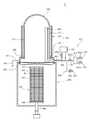
제 1 오존 공급 유닛(400)은 처리실(100) 내로 오존을 공급한다. 도 2는 제 1 오존 공급 유닛(400)의 내부 구조를 보여주기 위해 일부를 절단한 사시도이고, 도 3은 제 1 오존 공급 유닛(400)의 종단면도이며, 도 4는 도 3의 선 Ⅰ-Ⅰ을 따라 절단한 횡단면도이다. 도 2 내지 도 4를 참조하면, 제 1 오존 공급 유닛(400)은 오존 발생기(420), 오존 공급관(432), 오존 분사 노즐(440), 그리고 냉각 부재(460)를 가진다. 오존 발생기(420)는 처리실(100) 외부에 제공되며 오존을 발생시킨다. 오존 발생기(420)에는 오존 발생을 위해 사용되는 반응가스를 공급하는 반응가스 공급관이 연결된다. 예컨대, 반응가스 공급관은 산소를 공급하는 산소 공급관(422)과 수소를 공급하는 수소 공급관(424)을 포함한다. 오존 발생기(420)에서 발생된 오존은 오존 공급관(432)을 오존 분사 노즐(440)로 공급한다. 산소 공급관(422), 수소 공급관(424), 그리고 오존 공급관(432)에는 그 내부 통로를 개폐하거나 그 내부 통로로 흐르는 유체의 량을 조절하는 밸브(422a, 424a, 432a)가 설치된다.The first
오존 분사 노즐(440)은 긴 로드 형상을 가지며 수평부(442)와 수직부(444)를 가진다. 수평부(442)는 오존 공급관(432)과 연결되며 상술한 플랜지(140)에 형성된 입구를 통해 처리실(100) 내로 삽입된다. 수직부(444)는 수평부(442)의 끝단으로부터 상하 방향으로 수직하게 연장된다. 수직부(444)는 공정 튜브(120) 내에 위치된 보트(300)의 최상단에 적재된 웨이퍼(W)와 인접한 위치 또는 이보다 높은 위치까지 길게 연장된다. 수직부(444)에는 그 길이방향을 따라 복수의 분사구들이 형성된다. 분사구들은 동일 간격으로 배치될 수 있으며, 선택적으로 상부로 갈수록 조밀한 간격으로 배치될 수 있다.The
본 발명에 의하면, 산소(O2)와 수소(H2), 또는 이들을 포함하는 반응가스들을 처리실(100)로 공급하여 오존을 발생시키지 않고, 외부에서 발생된 오존을 직접 처리실(100)로 공급한다. 따라서 처리실(100) 내에서는 수소(H2)가 없는 분위기, 또는 공정 진행시 오존 발생 이외에 다른 이유로 수소를 처리실(100)로 공급하는 경우에는 수소의 량이 매우 작은 분위기에서 산화 공정을 진행한다. 따라서 확산 공 정시 웨이퍼에 형성된 산화막 내에 수소가 함유되어 산화막의 신뢰성을 저하시키는 것을 방지할 수 있다.According to the present invention, oxygen (O2 ), hydrogen (H2 ), or reaction gases including the same are supplied to the
또한, 본 발명에 의하면 오존을 외부에서 발생한 후 이를 처리실(100)로 공급하므로 처리실(100) 내 온도를 비교적 저온(예컨대, 약 800℃ 이하의 온도)으로 유지할 수 있다. 따라서 웨이퍼(W) 상에 약 10 내지 60Å 두께로 비교적 얇게 산화막을 형성할 수 있다.In addition, according to the present invention, since ozone is generated from the outside and supplied to the
일반적으로, 오존은 도 5에 도시된 바와 같이 고온에서 그 수명이 매우 짧다. 처리실(100) 내부는 가열 부재(160)에 의해 고온으로 유지되므로, 오존이 오존 분사 노즐(440)을 통해 웨이퍼(W)로 분사되기 전에 오존(O3)이 산소(O2)로 분해된다. 따라서 오존 분사 노즐(440)의 수직부(444)에서 상부로 갈수록 오존의 량이 크게 줄어들어, 상부에 위치될수록 웨이퍼(W)로 공급되는 오존의 량이 감소된다. 이로 인해 웨이퍼들(W) 간 산화막의 두께 균일도가 크게 저하된다.In general, ozone has a very short life at high temperatures as shown in FIG. 5. Since the inside of the
냉각 부재(460)는 오존 분사 노즐(440)을 냉각하여 오존 분사 노즐(440) 내에서 오존의 수명(lifetime)을 길게 한다. 다시 도 2 내지 도 4를 참조하면, 냉각 부재(460)는 냉각관(462), 온도 조절부(464), 냉각 유체 공급관(466), 냉각 유체 회수관(468), 그리고 분리판(469)을 가진다. 냉각관(462)은 오존 분사 노즐(440)을 전체적으로 감싸도록 배치된다. 따라서 냉각관(462)은 오존 분사 노즐(440)과 유사하게 수평부(462a)와 수직부(462b)를 가진다. 냉각관(462)은 횡단면이 대체로 직사각 형상으로 형성된다. 냉각관(462)에는 복수의 홀들이 형성된다. 홀들은 오존 분 사 노즐(440)에 형성된 분사구와 대응되는 위치에 각각 형성된다. 오존 분사 노즐(440)에 형성된 분사구 및 이와 대응되는 위치의 냉각관(462)에 형성된 홀에는 분사관(480)이 삽입된다. 분사관(480) 내에는 통공(480a)이 형성되어 오존 분사 노즐(440) 내로 공급된 오존은 분사관(480)들을 통해 웨이퍼(W)로 공급된다. 냉각관(462) 내에는 분리판(469)이 설치된다. 분리판(469)은 냉각관(462) 내 공간을 제 1 영역(463a)과 제 2 영역(463b)으로 분리한다.The cooling member 460 cools the
도 6은 분리판(469)의 일 예를 보여준다. 도 6을 참조하면, 분리판(469)은 수평부(469a)와 수직부(469b)를 가진다. 분리판(469)의 수평부(469a)는 냉각관(462)의 수평부(462a) 내에 배치되고, 분리판(469)의 수직부(462b)는 냉각관(462)의 수직부(462b) 내에 배치되며 분리판(469)의 수평부(469b)의 끝단으로부터 이와 수직하게 연장된다. 상술한 구조로 인해 제 1 영역(463a)은 분리판(469)의 전방에 위치되고, 제 2 영역(463b)은 분리판(469)의 후방에 위치된다. 제 1 영역(463a)과 제 2 영역(463b)이 냉각관(462)의 상단 영역(463c)에서 서로 통하도록 분리판(469)의 수직부(469b)는 냉각관(462)의 상단으로부터 이격되는 높이까지 연장된다. 분리판(469)에는 상술한 분사관(480)들이 삽입되는 관통홀들(469c)이 형성된다.6 shows an example of a separator 469. Referring to FIG. 6, the separator 469 has a
냉각관(462)의 제 1 영역(463a)에는 냉각 유체 공급관(466)이 연결되고, 제 2 영역(463b)에는 냉각 유체 회수관(468)이 연결된다. 냉각 유체 공급관(466)에는 그 내부 통로를 개폐하거나 그 내부를 흐르는 유체의 유량을 조절하는 밸브(466a)가 설치된다. 밸브(466a)로는 솔레노이드 밸브와 같이 전기적으로 제어 가능한 밸브가 사용된다. 온도 조절부(464)에서 온도 조절된 냉각 유체는 냉각 유체 공급관 (466)을 통해 제 1 영역(463a)으로 공급된다. 도 7에 도시된 바와 같이 냉각 유체는 제 1 영역(462a)에서 아래에서 위를 향하도록 흐른 후, 냉각관(462)의 상단에 제공된 영역(462c)을 통해 제 2 영역(462b)으로 유입된다. 냉각 유체는 제 2 영역(462b)에서 위에서 아래를 향하는 방향으로 흐른 후 냉각 유체 회수관(468)을 통해 온도 조절부(464)로 회수된다. 도 7에서 실선은 오존의 이동경로를 나타내고, 점선은 냉각 유체의 이동경로를 나타낸다. 제 1 영역(462a)과 제 2 영역(462b)을 흐르는 냉각 유체에 의해 오존 분사 노즐(440) 내 오존이 저온으로 유지된다.The cooling
일 예에 의하면, 냉각 유체로는 질소 가스와 같은 비활성 기체가 사용된다. 질소 가스는 상온 상태에서 냉각관(462)으로 공급될 수 있으며, 선택적으로 질소 가스는 온도 조절부(464)에서 오존의 냉각에 적합한 온도로 온도 조절된 후 냉각관(462)으로 공급될 수 있다. 이와 달리 냉각 유체로는 냉각수가 사용될 수 있다.In one example, an inert gas such as nitrogen gas is used as the cooling fluid. Nitrogen gas may be supplied to the
본 발명에 의하면, 처리실(100) 내에서 오존 분사 노즐(440) 내 오존이 냉각 유체에 의해 냉각되므로, 오존 분사 노즐(440) 내에서 오존의 수명이 길게 유지된다. 따라서 보트(300)에 적재된 전체 웨이퍼(W)에 대해 대체로 균일한 량의 오존이 공급되므로 웨이퍼들(W) 간 산화막의 두께 산포가 대체로 균일하다.According to the present invention, since the ozone in the
도 8은 본 발명의 산화 처리 장치(12)의 다른 예를 보여주는 도면이다. 도 8의 산화 처리 장치(12)에 의하면, 도 1의 산화 처리 장치(10)에 제공된 구성요소 이외에 공정 진행시 처리실(100) 내로 제거 가스를 공급하는 제거 가스 공급부재(600)가 더 제공된다. 공정 진행 중 처리실(100) 내 금속 파티클이 발생되며, 처리실(100) 내 금속 파티클이 산화막 내에 함유되면 산화막의 신뢰성을 크게 저하된 다. 이는 처리실(100) 내에 제공된 금속 재질의 구성물로부터 발생 될 수 있다.8 shows another example of the
제거 가스는 공정 진행시 처리실(100) 내 금속 파티클과 반응하고, 이에 의해 생성된 금속 반응물은 처리실(100)로부터 배기된다. 예컨대, 처리실(100) 내에서 발생되는 금속 파티클은 나트륨(Na), 철(Fe), 망간(Mn) 등일 수 있으며, 제거 가스로는 트리클로로에탄(trichloroethane; C2H3Cl3), 트리클로로에틸렌(trichloroethylene; C2HCl3), 또는 하이드로젼 클로라이드(Hydrogen chloride; HCl) 등이 사용될 수 있다. 제거 가스는 처리실(100) 내로 적정량 공급되는 것이 바람직하다. 제거 가스가 매우 적은 량으로 공급되면 금속의 제거가 충분히 이루어지지 않고, 제거 가스가 매우 많은 량으로 공급되면 제거 가스로부터 발생되는 수소가 다량 산화막 내로 함유될 수 있다. 예컨대, 처리실(100)로 공급되는 제거 가스는 산화 가스의 약 1/10에서 1/10000의 부피비 범위에서 공급되는 것이 바람직하다.The removal gas reacts with the metal particles in the
일 예에 의하면, 제거 가스 공급부재(600)는 오존 공급관(432)과 결합되는 제거 가스 공급관(620)을 가진다. 제거 가스 공급관(620)에는 그 내부 통로를 개폐하거나 그 내부 통로를 흐르는 제거 가스의 유량을 조절하는 밸브(622)가 설치된다. 상술한 구조로 인해, 제거 가스는 오존과 함께 오존 분사 노즐(440)을 통해 처리실(100)로 공급될 수 있다. 선택적으로 제거 가스 공급부재는 처리실(100) 내에 설치된 제거 가스 분사노즐(도시되지 않음)과 이에 결합된 제거 가스 공급관을 가지고, 제거 가스와 오존은 별개의 노즐을 통해 처리실(100) 내로 공급될 수 있다.According to one example, the removal
처리실(100) 내로 산소(O2)와 수소(H2)를 공급하여 처리실(100)에서 오존을 발생시키고, 여기에 하이드로젼 클로라이드(HCl)과 같은 제거 가스를 함께 공급하면 산소와 수소의 반응에 의해 생성된 물 분자와 하이드로젼 클로라이드 가스의 반응으로 인해 부식 등과 같은 악영향이 발생된다. 그러나 본 발명의 경우, 외부에서 오존을 발생시킨 후 이를 처리실(100)로 공급하므로 상술한 문제는 발생되지 않는다.Oxygen (O2 ) and hydrogen (H2 ) are supplied into the
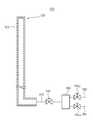
도 9는 본 발명의 산화 처리 장치(14)의 또 다른 예를 보여주는 도면이다. 도 9의 산화 처리 장치(14)는 도 1의 산화 처리 장치(10)에 제공된 구성요소 이외에 로드록 챔버(200)에 설치되는 제 2 오존 공급 유닛(500)을 더 포함한다. 제 2 오존 공급 유닛(500)은 보트(300)가 처리실(100)로 유입되기 전에 로드록 챔버(200)로 오존을 공급한다. 로드록 챔버(200)로 공급된 오존은 웨이퍼(W) 표면에서 탄화 수소(hydrocarbon)를 제거하고 로드록 챔버(200) 내에서 보트(300)에 적재된 웨이퍼들(W) 상에 보호막(passivation layer)을 형성한다.9 is a view showing still another example of the
보호막 형성 공정은 로드록 챔버(200) 내부를 상온으로 유지한 상태에서 수행하여, 웨이퍼들(W) 상에 비교적 얇은 두께의 보호막을 형성할 수 있다. 도 10은 도 9의 제 2 오존 공급 유닛(500)의 구조를 보여주는 도면이다. 도 10을 참조하면, 제 2 오존 공급 유닛(500)은 오존 분사 노즐(520), 오존 공급관(540), 그리고 오존 발생기(560)를 가진다. 오존 발생기(560)는 로드록 챔버(200)의 외부에 배치되며, 오존을 발생시킨다. 오존 발생기(560)에는 오존 발생에 필요한 반응가스를 공급하 는 반응가스 공급관이 연결된다. 반응가스 공급관은 산소를 공급하는 산소 공급관(562)과 수소를 공급하는 수소 공급관(564)을 포함한다. 산소 공급관(562)과 수소 공급관(564)에는 밸브(562a, 564a)가 설치된다.The protective film forming process may be performed while keeping the inside of the
오존 발생기(560)에서 발생된 오존은 오존 공급관(540)을 통해 오존 분사 노즐(520)로 공급된다. 오존 공급관(540)에는 그 내부 통로를 개폐하거나 그 내부 통로를 흐르는 오존의 유량을 조절하는 밸브(542)가 설치된다. 오존 분사 노즐(520)은 로드록 챔버(200) 내에 배치된다.Ozone generated from the
오존 분사 노즐(520)은 긴 로드 형상을 가지며, 상하 방향으로 수직하게 배치된다. 오존 분사 노즐(520)에는 그 길이방향을 따라 복수의 분사구들(522)이 형성되며, 오존 분사 노즐(520)은 보트(300)에 적재된 웨이퍼들(W) 전체에 대해 오존을 공급할 수 있도록 충분한 길이를 가진다.The
도 11은 본 발명의 산화 처리 장치(16)의 또 다른 예를 보여주는 도면이다. 도 11의 산화 처리 장치(16)는 도 1의 산화 처리 장치(10)에 제공된 구성요소 이외에 로드록 챔버(200)에 설치되는 제 2 오존 공급 유닛(500′)과 로드록 챔버(200)를 가열하는 가열 부재(260)를 가진다. 제 2 오존 공급 유닛(500′)은 제 1 오존 공급 유닛(300)과 동일한 구조를 가지고, 가열 부재(260)는 로드록 챔버(200)의 둘레를 감싸도록 배치된다. 도 11의 산화 처리 장치 사용시 로드록 챔버(200)에서 웨이퍼들(W) 상에 비교적 두꺼운 두께의 보호막을 형성할 수 있다.11 is a view showing another example of the
본 발명에 의하면, 웨이퍼들(W)이 처리실(100)로 유입되기 전에 로드록 챔버(200)로 오존을 공급하여 로드록 챔버(200)에서 웨이퍼들(W)에 대해 초기 산화를 진행하여 탄화 수소를 제거하므로 처리실(100)에서 산화 공정 수행시 웨이퍼(W) 상에 양질의 산화막을 형성할 수 있다.According to the present invention, before the wafers W are introduced into the
다음에는 상술한 장치를 사용하여 확산 공정을 수행하는 방법을 순차적으로 설명한다.Next, a method of performing the diffusion process using the above-described apparatus will be described sequentially.
처음에 로드록 챔버(200) 내에 배치된 보트(300)로 웨이퍼들(W)이 적재된다. 로드록 챔버(200) 내로 오존이 공급되어, 웨이퍼(W) 상에 탄화 수소(hydrocarbon)를 제거하고 보호막을 형성한다. 이때, 로드록 챔버(200)의 온도는 상온 내지 약 150℃의 온도로 유지될 수 있으며, 웨이퍼(W)에는 약 2 내지 10Å 두께로 보호막이 형성될 수 있다. 고온에서 공정이 수행되는 경우, 오존 분사 노즐(440)은 냉각 부재(460)에 의해 냉각될 수 있다.The wafers W are initially loaded into a
이후, 보트(300)는 처리실(100)로 유입된다. 오존 발생기(420)에 오존이 발생된 후, 오존 분사 노즐(440)로 공급된다. 오존 분사 노즐(440) 둘레에 제공된 냉각관(462)으로 냉각된 질소 가스가 공급되어 오존 분사 노즐(440) 내에서 오존이 분해되는 것을 방지한다. 또한, 오존 분사 노즐(440)을 통해 처리실(100)로 오존이 분사되어, 웨이퍼(W) 상에 산화막을 형성한다. 이와 함께, 제거 가스 공급관을 통해 제거 가스가 공급되어 처리실(100) 내 금속 파티클을 처리실(100)로부터 제거한다.Thereafter, the
상술한 실시예에서는 보트에 복수의 웨이퍼들이 적층되어 배치된 상태에서 공정을 수행하는 장치를 예로 들어 설명하였다. 그러나 이는 일 예에 불과하며, 본 발명의 기술적 사상은 하나의 웨이퍼에 대해 공정을 수행하는 장치에도 적용될 수 있다.In the above embodiment, an apparatus for performing a process in a state in which a plurality of wafers are stacked and arranged in a boat has been described as an example. However, this is only an example, and the inventive concept may be applied to an apparatus that performs a process on one wafer.
본 발명에 의하면, 산화 공정시 외부에서 오존을 발생한 후 처리실 내로 공급하므로 웨이퍼 상에 형성된 산화막 내에 수소가 함유되어 산화막의 신뢰성을 저하시키는 것을 방지할 수 있다.According to the present invention, since ozone is externally generated during the oxidation process and then supplied into the processing chamber, hydrogen can be contained in the oxide film formed on the wafer, thereby preventing the reliability of the oxide film from being lowered.
또한, 본 발명에 의하면 오존을 외부에서 발생한 후 이를 처리실(100)로 공급하므로 처리실 내 온도를 비교적 저온으로 유지할 수 있어, 비교적 얇은 두께의 산화막을 형성할 수 있다.In addition, according to the present invention, since ozone is generated from the outside and supplied to the
또한, 본 발명에 의하면, 처리실 내 오존 분사 노즐이 냉각 부재에 의해 냉각되므로 오존 분사 노즐 전체 영역에서 오존이 분해되는 것을 최소화할 수 있다.Further, according to the present invention, since the ozone injection nozzle in the processing chamber is cooled by the cooling member, it is possible to minimize the decomposition of ozone in the entire area of the ozone injection nozzle.
또한, 본 발명에 의하면, 제거 가스에 의해 처리실 내 금속 파티클 등이 제거되므로, 산화 공정에 의해 형성된 산화막의 신뢰성이 저하되는 것을 방지할 수 있다.Moreover, according to this invention, since metal particle etc. in a process chamber are removed by removal gas, the reliability of the oxide film formed by the oxidation process can be prevented.
또한, 본 발명에 의하면, 로드록 챔버에서 웨이퍼들에 대해 초기 산화를 진행하여 탄화 수소를 제거하므로, 처리실에서 산화 공정 수행시 웨이퍼 상에 양질의 산화막을 형성할 수 있다.In addition, according to the present invention, since the hydrocarbon is removed by performing initial oxidation on the wafers in the load lock chamber, it is possible to form a high quality oxide film on the wafer during the oxidation process in the processing chamber.
Claims (22)
Translated fromKoreanPriority Applications (2)
| Application Number | Priority Date | Filing Date | Title |
|---|---|---|---|
| KR1020050116482AKR100706790B1 (en) | 2005-12-01 | 2005-12-01 | Oxidation treatment apparatus and method |
| US11/563,980US20070134415A1 (en) | 2005-12-01 | 2006-11-28 | Oxidation Treatment Apparatus and Method |
Applications Claiming Priority (1)
| Application Number | Priority Date | Filing Date | Title |
|---|---|---|---|
| KR1020050116482AKR100706790B1 (en) | 2005-12-01 | 2005-12-01 | Oxidation treatment apparatus and method |
Publications (1)
| Publication Number | Publication Date |
|---|---|
| KR100706790B1true KR100706790B1 (en) | 2007-04-12 |
Family
ID=38161679
Family Applications (1)
| Application Number | Title | Priority Date | Filing Date |
|---|---|---|---|
| KR1020050116482AExpired - Fee RelatedKR100706790B1 (en) | 2005-12-01 | 2005-12-01 | Oxidation treatment apparatus and method |
Country Status (2)
| Country | Link |
|---|---|
| US (1) | US20070134415A1 (en) |
| KR (1) | KR100706790B1 (en) |
Cited By (1)
| Publication number | Priority date | Publication date | Assignee | Title |
|---|---|---|---|---|
| WO2016171452A1 (en)* | 2015-04-21 | 2016-10-27 | 주식회사 유진테크 | Substrate processing apparatus and method for cleaning chamber |
Families Citing this family (10)
| Publication number | Priority date | Publication date | Assignee | Title |
|---|---|---|---|---|
| KR101047230B1 (en)* | 2006-03-28 | 2011-07-06 | 가부시키가이샤 히다치 고쿠사이 덴키 | Substrate treating apparatus |
| JP5616591B2 (en)* | 2008-06-20 | 2014-10-29 | 株式会社日立国際電気 | Semiconductor device manufacturing method and substrate processing apparatus |
| KR100996210B1 (en)* | 2010-04-12 | 2010-11-24 | 세메스 주식회사 | Gas injection unit and apparatus and method for depositing thin layer with the same |
| KR101205436B1 (en)* | 2011-01-04 | 2012-11-28 | 삼성전자주식회사 | Chemical Vapor Deposition Apparatus |
| DE102012101456A1 (en) | 2012-02-23 | 2013-08-29 | Schott Solar Ag | Process for producing a solar cell |
| JP6002312B2 (en)* | 2012-03-28 | 2016-10-05 | クックジェ エレクトリック コリア カンパニー リミテッド | Equipment and cluster equipment for selective epitaxial growth |
| US20140144380A1 (en)* | 2012-11-28 | 2014-05-29 | Samsung Electronics Co., Ltd. | Gas supply pipes and chemical vapor deposition apparatus |
| RU2548835C1 (en)* | 2013-11-01 | 2015-04-20 | Елена Анатольевна Чекалова | Making of wear-proof coating on metal part surface |
| JP6860048B2 (en)* | 2019-08-30 | 2021-04-14 | 株式会社明電舎 | Atomic layer deposition method |
| CN113755823B (en)* | 2021-09-07 | 2023-10-13 | 北京北方华创微电子装备有限公司 | Gas injection device of semiconductor heat treatment equipment and semiconductor heat treatment equipment |
Citations (4)
| Publication number | Priority date | Publication date | Assignee | Title |
|---|---|---|---|---|
| KR980005855A (en)* | 1996-06-29 | 1998-03-30 | 김광호 | Method of forming oxide film and apparatus |
| KR0137593B1 (en)* | 1994-11-05 | 1998-06-01 | 양승택 | Method of ozone high pressure oxidation |
| KR20010020883A (en)* | 1999-05-24 | 2001-03-15 | 히가시 데쓰로 | Oxidation processing unit |
| KR20050049377A (en)* | 2003-11-20 | 2005-05-25 | 도쿄 엘렉트론 가부시키가이샤 | Oxidation method and apparatus for object to be processed |
Family Cites Families (20)
| Publication number | Priority date | Publication date | Assignee | Title |
|---|---|---|---|---|
| US4341592A (en)* | 1975-08-04 | 1982-07-27 | Texas Instruments Incorporated | Method for removing photoresist layer from substrate by ozone treatment |
| JPS61191015A (en)* | 1985-02-20 | 1986-08-25 | Hitachi Ltd | Semiconductor vapor phase growth method and device |
| US4812201A (en)* | 1986-07-25 | 1989-03-14 | Tokyo Electron Limited | Method of ashing layers, and apparatus for ashing layers |
| KR0155158B1 (en)* | 1989-07-25 | 1998-12-01 | 카자마 젠쥬 | Vertical processing device and processing method |
| JP2662722B2 (en)* | 1990-01-12 | 1997-10-15 | 東京エレクトロン株式会社 | Batch type heat treatment equipment |
| US5407350A (en)* | 1992-02-13 | 1995-04-18 | Tokyo Electron Limited | Heat-treatment apparatus |
| US5447294A (en)* | 1993-01-21 | 1995-09-05 | Tokyo Electron Limited | Vertical type heat treatment system |
| US5484484A (en)* | 1993-07-03 | 1996-01-16 | Tokyo Electron Kabushiki | Thermal processing method and apparatus therefor |
| JPH0786271A (en)* | 1993-09-17 | 1995-03-31 | Fujitsu Ltd | Method for producing silicon oxide film |
| TW273574B (en)* | 1993-12-10 | 1996-04-01 | Tokyo Electron Co Ltd | |
| JP3583467B2 (en)* | 1994-05-30 | 2004-11-04 | 株式会社東芝 | Apparatus and method for manufacturing semiconductor device |
| US5709754A (en)* | 1995-12-29 | 1998-01-20 | Micron Technology, Inc. | Method and apparatus for removing photoresist using UV and ozone/oxygen mixture |
| JP3523986B2 (en)* | 1997-07-02 | 2004-04-26 | シャープ株式会社 | Method and apparatus for manufacturing polycrystalline semiconductor |
| US6709715B1 (en)* | 1999-06-17 | 2004-03-23 | Applied Materials Inc. | Plasma enhanced chemical vapor deposition of copolymer of parylene N and comonomers with various double bonds |
| US6376387B2 (en)* | 1999-07-09 | 2002-04-23 | Applied Materials, Inc. | Method of sealing an epitaxial silicon layer on a substrate |
| KR100406174B1 (en)* | 2000-06-15 | 2003-11-19 | 주식회사 하이닉스반도체 | Showerhead used chemically enhanced chemical vapor deposition equipment |
| US20060042757A1 (en)* | 2004-08-27 | 2006-03-02 | Seiichiro Kanno | Wafer processing apparatus capable of controlling wafer temperature |
| DE102004046821A1 (en)* | 2004-09-27 | 2006-04-06 | Siemens Ag | Cooling device of an electrical machine |
| US7972441B2 (en)* | 2005-04-05 | 2011-07-05 | Applied Materials, Inc. | Thermal oxidation of silicon using ozone |
| US20070091540A1 (en)* | 2005-10-20 | 2007-04-26 | Applied Materials, Inc. | Method of processing a workpiece in a plasma reactor using multiple zone feed forward thermal control |
- 2005
- 2005-12-01KRKR1020050116482Apatent/KR100706790B1/ennot_activeExpired - Fee Related
- 2006
- 2006-11-28USUS11/563,980patent/US20070134415A1/ennot_activeAbandoned
Patent Citations (4)
| Publication number | Priority date | Publication date | Assignee | Title |
|---|---|---|---|---|
| KR0137593B1 (en)* | 1994-11-05 | 1998-06-01 | 양승택 | Method of ozone high pressure oxidation |
| KR980005855A (en)* | 1996-06-29 | 1998-03-30 | 김광호 | Method of forming oxide film and apparatus |
| KR20010020883A (en)* | 1999-05-24 | 2001-03-15 | 히가시 데쓰로 | Oxidation processing unit |
| KR20050049377A (en)* | 2003-11-20 | 2005-05-25 | 도쿄 엘렉트론 가부시키가이샤 | Oxidation method and apparatus for object to be processed |
Cited By (1)
| Publication number | Priority date | Publication date | Assignee | Title |
|---|---|---|---|---|
| WO2016171452A1 (en)* | 2015-04-21 | 2016-10-27 | 주식회사 유진테크 | Substrate processing apparatus and method for cleaning chamber |
Also Published As
| Publication number | Publication date |
|---|---|
| US20070134415A1 (en) | 2007-06-14 |
Similar Documents
| Publication | Publication Date | Title |
|---|---|---|
| US20070134415A1 (en) | Oxidation Treatment Apparatus and Method | |
| KR100684910B1 (en) | Plasma processing apparatus and its cleaning method | |
| KR102068368B1 (en) | Purging device and purging method for substrate-containing vessel | |
| JP2021073697A (en) | System of substrate processing with environment control of substrate carrier and purge chamber, apparatus, and method | |
| TWI423326B (en) | Oxidation device and method for semiconductor process | |
| US20090104792A1 (en) | Semiconductor Device Producing Method | |
| US7926445B2 (en) | Oxidizing method and oxidizing unit for object to be processed | |
| US20080268654A1 (en) | Oxidizing method and oxidizing unit for object to be processed | |
| KR100605884B1 (en) | Surface treatment method and surface treatment apparatus | |
| US20180258534A1 (en) | Gas spraying apparatus, substrate processing facility including the same, and method for processing substrate using substrate processing facility | |
| JP7047117B2 (en) | Manufacturing method of semiconductor device, substrate processing device and recording medium | |
| KR100905899B1 (en) | Substrate lifting unit, substrate processing apparatus and method using same | |
| US20230207289A1 (en) | Support unit and apparatus for treating substrate with the unit | |
| JP4086054B2 (en) | Process for oxidizing object, oxidation apparatus and storage medium | |
| KR102771375B1 (en) | Substrate processing apparatus and cleaning method | |
| US20210310739A1 (en) | Cleaning method and heat treatment apparatus | |
| JP6937332B2 (en) | Substrate processing equipment, semiconductor equipment manufacturing methods and programs | |
| KR20080062339A (en) | Substrate treatment apparatus and method for manufacturing same | |
| KR20200059419A (en) | Method for treating substrate and apparatus for treating substrate | |
| JPH0355841A (en) | Vertical type processing equipment | |
| JP2020147833A6 (en) | Substrate processing equipment, semiconductor equipment manufacturing methods and programs | |
| KR20080062211A (en) | Apparatus and Method for Processing Substrates | |
| KR102869344B1 (en) | Buffer unit and method for treating substrate using the same | |
| KR100978131B1 (en) | Substrate processing apparatus | |
| KR20140033900A (en) | Substrate processing method |
Legal Events
| Date | Code | Title | Description |
|---|---|---|---|
| A201 | Request for examination | ||
| PA0109 | Patent application | St.27 status event code:A-0-1-A10-A12-nap-PA0109 | |
| PA0201 | Request for examination | St.27 status event code:A-1-2-D10-D11-exm-PA0201 | |
| D13-X000 | Search requested | St.27 status event code:A-1-2-D10-D13-srh-X000 | |
| D14-X000 | Search report completed | St.27 status event code:A-1-2-D10-D14-srh-X000 | |
| E902 | Notification of reason for refusal | ||
| PE0902 | Notice of grounds for rejection | St.27 status event code:A-1-2-D10-D21-exm-PE0902 | |
| P11-X000 | Amendment of application requested | St.27 status event code:A-2-2-P10-P11-nap-X000 | |
| P13-X000 | Application amended | St.27 status event code:A-2-2-P10-P13-nap-X000 | |
| E701 | Decision to grant or registration of patent right | ||
| PE0701 | Decision of registration | St.27 status event code:A-1-2-D10-D22-exm-PE0701 | |
| GRNT | Written decision to grant | ||
| PR0701 | Registration of establishment | St.27 status event code:A-2-4-F10-F11-exm-PR0701 | |
| PR1002 | Payment of registration fee | St.27 status event code:A-2-2-U10-U11-oth-PR1002 Fee payment year number:1 | |
| PG1601 | Publication of registration | St.27 status event code:A-4-4-Q10-Q13-nap-PG1601 | |
| PR1001 | Payment of annual fee | St.27 status event code:A-4-4-U10-U11-oth-PR1001 Fee payment year number:4 | |
| PR1001 | Payment of annual fee | St.27 status event code:A-4-4-U10-U11-oth-PR1001 Fee payment year number:5 | |
| FPAY | Annual fee payment | ||
| PR1001 | Payment of annual fee | St.27 status event code:A-4-4-U10-U11-oth-PR1001 Fee payment year number:6 | |
| R18-X000 | Changes to party contact information recorded | St.27 status event code:A-5-5-R10-R18-oth-X000 | |
| FPAY | Annual fee payment | ||
| PR1001 | Payment of annual fee | St.27 status event code:A-4-4-U10-U11-oth-PR1001 Fee payment year number:7 | |
| PR1001 | Payment of annual fee | St.27 status event code:A-4-4-U10-U11-oth-PR1001 Fee payment year number:8 | |
| LAPS | Lapse due to unpaid annual fee | ||
| PC1903 | Unpaid annual fee | St.27 status event code:A-4-4-U10-U13-oth-PC1903 Not in force date:20150406 Payment event data comment text:Termination Category : DEFAULT_OF_REGISTRATION_FEE | |
| PC1903 | Unpaid annual fee | St.27 status event code:N-4-6-H10-H13-oth-PC1903 Ip right cessation event data comment text:Termination Category : DEFAULT_OF_REGISTRATION_FEE Not in force date:20150406 | |
| P22-X000 | Classification modified | St.27 status event code:A-4-4-P10-P22-nap-X000 |