KR100704324B1 - Automated Analytical Instruments and Automated Analytical Methods - Google Patents
Automated Analytical Instruments and Automated Analytical MethodsDownload PDFInfo
- Publication number
- KR100704324B1 KR100704324B1KR1020007012142AKR20007012142AKR100704324B1KR 100704324 B1KR100704324 B1KR 100704324B1KR 1020007012142 AKR1020007012142 AKR 1020007012142AKR 20007012142 AKR20007012142 AKR 20007012142AKR 100704324 B1KR100704324 B1KR 100704324B1
- Authority
- KR
- South Korea
- Prior art keywords
- station
- receptacle
- mtu
- reaction receptacle
- amplification
- Prior art date
- Legal status (The legal status is an assumption and is not a legal conclusion. Google has not performed a legal analysis and makes no representation as to the accuracy of the status listed.)
- Expired - Fee Related
Links
Images


Classifications
- C—CHEMISTRY; METALLURGY
- C12—BIOCHEMISTRY; BEER; SPIRITS; WINE; VINEGAR; MICROBIOLOGY; ENZYMOLOGY; MUTATION OR GENETIC ENGINEERING
- C12Q—MEASURING OR TESTING PROCESSES INVOLVING ENZYMES, NUCLEIC ACIDS OR MICROORGANISMS; COMPOSITIONS OR TEST PAPERS THEREFOR; PROCESSES OF PREPARING SUCH COMPOSITIONS; CONDITION-RESPONSIVE CONTROL IN MICROBIOLOGICAL OR ENZYMOLOGICAL PROCESSES
- C12Q1/00—Measuring or testing processes involving enzymes, nucleic acids or microorganisms; Compositions therefor; Processes of preparing such compositions
- C12Q1/68—Measuring or testing processes involving enzymes, nucleic acids or microorganisms; Compositions therefor; Processes of preparing such compositions involving nucleic acids
- C12Q1/6813—Hybridisation assays
- C12Q1/6834—Enzymatic or biochemical coupling of nucleic acids to a solid phase
- G—PHYSICS
- G01—MEASURING; TESTING
- G01N—INVESTIGATING OR ANALYSING MATERIALS BY DETERMINING THEIR CHEMICAL OR PHYSICAL PROPERTIES
- G01N33/00—Investigating or analysing materials by specific methods not covered by groups G01N1/00 - G01N31/00
- G01N33/48—Biological material, e.g. blood, urine; Haemocytometers
- G01N33/50—Chemical analysis of biological material, e.g. blood, urine; Testing involving biospecific ligand binding methods; Immunological testing
- B—PERFORMING OPERATIONS; TRANSPORTING
- B01—PHYSICAL OR CHEMICAL PROCESSES OR APPARATUS IN GENERAL
- B01F—MIXING, e.g. DISSOLVING, EMULSIFYING OR DISPERSING
- B01F29/00—Mixers with rotating receptacles
- B01F29/10—Mixers with rotating receptacles with receptacles rotated about two different axes, e.g. receptacles having planetary motion
- B—PERFORMING OPERATIONS; TRANSPORTING
- B01—PHYSICAL OR CHEMICAL PROCESSES OR APPARATUS IN GENERAL
- B01F—MIXING, e.g. DISSOLVING, EMULSIFYING OR DISPERSING
- B01F29/00—Mixers with rotating receptacles
- B01F29/30—Mixing the contents of individual packages or containers, e.g. by rotating tins or bottles
- B01F29/32—Containers specially adapted for coupling to rotating frames or the like; Coupling means therefor
- B01F29/322—Containers specially adapted for coupling to rotating frames or the like; Coupling means therefor of two or more containers supported for simultaneous mixing, e.g. for bottles in crates
- B—PERFORMING OPERATIONS; TRANSPORTING
- B01—PHYSICAL OR CHEMICAL PROCESSES OR APPARATUS IN GENERAL
- B01L—CHEMICAL OR PHYSICAL LABORATORY APPARATUS FOR GENERAL USE
- B01L7/00—Heating or cooling apparatus; Heat insulating devices
- B01L7/52—Heating or cooling apparatus; Heat insulating devices with provision for submitting samples to a predetermined sequence of different temperatures, e.g. for treating nucleic acid samples
- B01L7/525—Heating or cooling apparatus; Heat insulating devices with provision for submitting samples to a predetermined sequence of different temperatures, e.g. for treating nucleic acid samples with physical movement of samples between temperature zones
- B01L7/5255—Heating or cooling apparatus; Heat insulating devices with provision for submitting samples to a predetermined sequence of different temperatures, e.g. for treating nucleic acid samples with physical movement of samples between temperature zones by moving sample containers
- B—PERFORMING OPERATIONS; TRANSPORTING
- B03—SEPARATION OF SOLID MATERIALS USING LIQUIDS OR USING PNEUMATIC TABLES OR JIGS; MAGNETIC OR ELECTROSTATIC SEPARATION OF SOLID MATERIALS FROM SOLID MATERIALS OR FLUIDS; SEPARATION BY HIGH-VOLTAGE ELECTRIC FIELDS
- B03C—MAGNETIC OR ELECTROSTATIC SEPARATION OF SOLID MATERIALS FROM SOLID MATERIALS OR FLUIDS; SEPARATION BY HIGH-VOLTAGE ELECTRIC FIELDS
- B03C1/00—Magnetic separation
- B03C1/02—Magnetic separation acting directly on the substance being separated
- B03C1/28—Magnetic plugs and dipsticks
- B03C1/282—Magnetic plugs and dipsticks with associated accumulation indicator, e.g. Hall sensor
- B—PERFORMING OPERATIONS; TRANSPORTING
- B03—SEPARATION OF SOLID MATERIALS USING LIQUIDS OR USING PNEUMATIC TABLES OR JIGS; MAGNETIC OR ELECTROSTATIC SEPARATION OF SOLID MATERIALS FROM SOLID MATERIALS OR FLUIDS; SEPARATION BY HIGH-VOLTAGE ELECTRIC FIELDS
- B03C—MAGNETIC OR ELECTROSTATIC SEPARATION OF SOLID MATERIALS FROM SOLID MATERIALS OR FLUIDS; SEPARATION BY HIGH-VOLTAGE ELECTRIC FIELDS
- B03C1/00—Magnetic separation
- B03C1/02—Magnetic separation acting directly on the substance being separated
- B03C1/28—Magnetic plugs and dipsticks
- B03C1/288—Magnetic plugs and dipsticks disposed at the outer circumference of a recipient
- B—PERFORMING OPERATIONS; TRANSPORTING
- B03—SEPARATION OF SOLID MATERIALS USING LIQUIDS OR USING PNEUMATIC TABLES OR JIGS; MAGNETIC OR ELECTROSTATIC SEPARATION OF SOLID MATERIALS FROM SOLID MATERIALS OR FLUIDS; SEPARATION BY HIGH-VOLTAGE ELECTRIC FIELDS
- B03C—MAGNETIC OR ELECTROSTATIC SEPARATION OF SOLID MATERIALS FROM SOLID MATERIALS OR FLUIDS; SEPARATION BY HIGH-VOLTAGE ELECTRIC FIELDS
- B03C1/00—Magnetic separation
- B03C1/02—Magnetic separation acting directly on the substance being separated
- B03C1/30—Combinations with other devices, not otherwise provided for
- C—CHEMISTRY; METALLURGY
- C12—BIOCHEMISTRY; BEER; SPIRITS; WINE; VINEGAR; MICROBIOLOGY; ENZYMOLOGY; MUTATION OR GENETIC ENGINEERING
- C12Q—MEASURING OR TESTING PROCESSES INVOLVING ENZYMES, NUCLEIC ACIDS OR MICROORGANISMS; COMPOSITIONS OR TEST PAPERS THEREFOR; PROCESSES OF PREPARING SUCH COMPOSITIONS; CONDITION-RESPONSIVE CONTROL IN MICROBIOLOGICAL OR ENZYMOLOGICAL PROCESSES
- C12Q1/00—Measuring or testing processes involving enzymes, nucleic acids or microorganisms; Compositions therefor; Processes of preparing such compositions
- C12Q1/68—Measuring or testing processes involving enzymes, nucleic acids or microorganisms; Compositions therefor; Processes of preparing such compositions involving nucleic acids
- C12Q1/6813—Hybridisation assays
- C12Q1/6832—Enhancement of hybridisation reaction
- G—PHYSICS
- G01—MEASURING; TESTING
- G01N—INVESTIGATING OR ANALYSING MATERIALS BY DETERMINING THEIR CHEMICAL OR PHYSICAL PROPERTIES
- G01N35/00—Automatic analysis not limited to methods or materials provided for in any single one of groups G01N1/00 - G01N33/00; Handling materials therefor
- G01N35/02—Automatic analysis not limited to methods or materials provided for in any single one of groups G01N1/00 - G01N33/00; Handling materials therefor using a plurality of sample containers moved by a conveyor system past one or more treatment or analysis stations
- G01N35/025—Automatic analysis not limited to methods or materials provided for in any single one of groups G01N1/00 - G01N33/00; Handling materials therefor using a plurality of sample containers moved by a conveyor system past one or more treatment or analysis stations having a carousel or turntable for reaction cells or cuvettes
- B—PERFORMING OPERATIONS; TRANSPORTING
- B01—PHYSICAL OR CHEMICAL PROCESSES OR APPARATUS IN GENERAL
- B01F—MIXING, e.g. DISSOLVING, EMULSIFYING OR DISPERSING
- B01F29/00—Mixers with rotating receptacles
- B01F29/40—Parts or components, e.g. receptacles, feeding or discharging means
- B01F29/403—Disposition of the rotor axis
- B01F29/4035—Disposition of the rotor axis with a receptacle rotating around two or more axes
- B01F29/40354—Disposition of the rotor axis with a receptacle rotating around two or more axes arranged for planetary motion
- B—PERFORMING OPERATIONS; TRANSPORTING
- B01—PHYSICAL OR CHEMICAL PROCESSES OR APPARATUS IN GENERAL
- B01L—CHEMICAL OR PHYSICAL LABORATORY APPARATUS FOR GENERAL USE
- B01L2200/00—Solutions for specific problems relating to chemical or physical laboratory apparatus
- B01L2200/14—Process control and prevention of errors
- B01L2200/143—Quality control, feedback systems
- B01L2200/147—Employing temperature sensors
- B—PERFORMING OPERATIONS; TRANSPORTING
- B01—PHYSICAL OR CHEMICAL PROCESSES OR APPARATUS IN GENERAL
- B01L—CHEMICAL OR PHYSICAL LABORATORY APPARATUS FOR GENERAL USE
- B01L2300/00—Additional constructional details
- B01L2300/18—Means for temperature control
- B01L2300/1805—Conductive heating, heat from thermostatted solids is conducted to receptacles, e.g. heating plates, blocks
- B01L2300/1822—Conductive heating, heat from thermostatted solids is conducted to receptacles, e.g. heating plates, blocks using Peltier elements
- B—PERFORMING OPERATIONS; TRANSPORTING
- B01—PHYSICAL OR CHEMICAL PROCESSES OR APPARATUS IN GENERAL
- B01L—CHEMICAL OR PHYSICAL LABORATORY APPARATUS FOR GENERAL USE
- B01L2300/00—Additional constructional details
- B01L2300/18—Means for temperature control
- B01L2300/1805—Conductive heating, heat from thermostatted solids is conducted to receptacles, e.g. heating plates, blocks
- B01L2300/1827—Conductive heating, heat from thermostatted solids is conducted to receptacles, e.g. heating plates, blocks using resistive heater
- B—PERFORMING OPERATIONS; TRANSPORTING
- B01—PHYSICAL OR CHEMICAL PROCESSES OR APPARATUS IN GENERAL
- B01L—CHEMICAL OR PHYSICAL LABORATORY APPARATUS FOR GENERAL USE
- B01L9/00—Supporting devices; Holding devices
- B01L9/06—Test-tube stands; Test-tube holders
- B—PERFORMING OPERATIONS; TRANSPORTING
- B03—SEPARATION OF SOLID MATERIALS USING LIQUIDS OR USING PNEUMATIC TABLES OR JIGS; MAGNETIC OR ELECTROSTATIC SEPARATION OF SOLID MATERIALS FROM SOLID MATERIALS OR FLUIDS; SEPARATION BY HIGH-VOLTAGE ELECTRIC FIELDS
- B03C—MAGNETIC OR ELECTROSTATIC SEPARATION OF SOLID MATERIALS FROM SOLID MATERIALS OR FLUIDS; SEPARATION BY HIGH-VOLTAGE ELECTRIC FIELDS
- B03C2201/00—Details of magnetic or electrostatic separation
- B03C2201/26—Details of magnetic or electrostatic separation for use in medical or biological applications
- C—CHEMISTRY; METALLURGY
- C12—BIOCHEMISTRY; BEER; SPIRITS; WINE; VINEGAR; MICROBIOLOGY; ENZYMOLOGY; MUTATION OR GENETIC ENGINEERING
- C12Q—MEASURING OR TESTING PROCESSES INVOLVING ENZYMES, NUCLEIC ACIDS OR MICROORGANISMS; COMPOSITIONS OR TEST PAPERS THEREFOR; PROCESSES OF PREPARING SUCH COMPOSITIONS; CONDITION-RESPONSIVE CONTROL IN MICROBIOLOGICAL OR ENZYMOLOGICAL PROCESSES
- C12Q2537/00—Reactions characterised by the reaction format or use of a specific feature
- C12Q2537/10—Reactions characterised by the reaction format or use of a specific feature the purpose or use of
- G—PHYSICS
- G01—MEASURING; TESTING
- G01N—INVESTIGATING OR ANALYSING MATERIALS BY DETERMINING THEIR CHEMICAL OR PHYSICAL PROPERTIES
- G01N35/00—Automatic analysis not limited to methods or materials provided for in any single one of groups G01N1/00 - G01N33/00; Handling materials therefor
- G01N2035/00346—Heating or cooling arrangements
- G01N2035/00356—Holding samples at elevated temperature (incubation)
- G—PHYSICS
- G01—MEASURING; TESTING
- G01N—INVESTIGATING OR ANALYSING MATERIALS BY DETERMINING THEIR CHEMICAL OR PHYSICAL PROPERTIES
- G01N35/00—Automatic analysis not limited to methods or materials provided for in any single one of groups G01N1/00 - G01N33/00; Handling materials therefor
- G01N2035/00465—Separating and mixing arrangements
- G01N2035/00524—Mixing by agitating sample carrier
- G—PHYSICS
- G01—MEASURING; TESTING
- G01N—INVESTIGATING OR ANALYSING MATERIALS BY DETERMINING THEIR CHEMICAL OR PHYSICAL PROPERTIES
- G01N35/00—Automatic analysis not limited to methods or materials provided for in any single one of groups G01N1/00 - G01N33/00; Handling materials therefor
- G01N35/02—Automatic analysis not limited to methods or materials provided for in any single one of groups G01N1/00 - G01N33/00; Handling materials therefor using a plurality of sample containers moved by a conveyor system past one or more treatment or analysis stations
- G01N35/04—Details of the conveyor system
- G01N2035/0401—Sample carriers, cuvettes or reaction vessels
- G01N2035/0437—Cleaning cuvettes or reaction vessels
- G—PHYSICS
- G01—MEASURING; TESTING
- G01N—INVESTIGATING OR ANALYSING MATERIALS BY DETERMINING THEIR CHEMICAL OR PHYSICAL PROPERTIES
- G01N35/00—Automatic analysis not limited to methods or materials provided for in any single one of groups G01N1/00 - G01N33/00; Handling materials therefor
- G01N35/02—Automatic analysis not limited to methods or materials provided for in any single one of groups G01N1/00 - G01N33/00; Handling materials therefor using a plurality of sample containers moved by a conveyor system past one or more treatment or analysis stations
- G01N35/04—Details of the conveyor system
- G01N2035/0439—Rotary sample carriers, i.e. carousels
- G01N2035/0453—Multiple carousels working in parallel
- G01N2035/0455—Coaxial carousels
- G—PHYSICS
- G01—MEASURING; TESTING
- G01N—INVESTIGATING OR ANALYSING MATERIALS BY DETERMINING THEIR CHEMICAL OR PHYSICAL PROPERTIES
- G01N35/00—Automatic analysis not limited to methods or materials provided for in any single one of groups G01N1/00 - G01N33/00; Handling materials therefor
- G01N35/10—Devices for transferring samples or any liquids to, in, or from, the analysis apparatus, e.g. suction devices, injection devices
- G01N2035/1027—General features of the devices
- G01N2035/103—General features of the devices using disposable tips
- G—PHYSICS
- G01—MEASURING; TESTING
- G01N—INVESTIGATING OR ANALYSING MATERIALS BY DETERMINING THEIR CHEMICAL OR PHYSICAL PROPERTIES
- G01N35/00—Automatic analysis not limited to methods or materials provided for in any single one of groups G01N1/00 - G01N33/00; Handling materials therefor
- G01N35/0098—Automatic analysis not limited to methods or materials provided for in any single one of groups G01N1/00 - G01N33/00; Handling materials therefor involving analyte bound to insoluble magnetic carrier, e.g. using magnetic separation
- G—PHYSICS
- G01—MEASURING; TESTING
- G01N—INVESTIGATING OR ANALYSING MATERIALS BY DETERMINING THEIR CHEMICAL OR PHYSICAL PROPERTIES
- G01N35/00—Automatic analysis not limited to methods or materials provided for in any single one of groups G01N1/00 - G01N33/00; Handling materials therefor
- G01N35/0099—Automatic analysis not limited to methods or materials provided for in any single one of groups G01N1/00 - G01N33/00; Handling materials therefor comprising robots or similar manipulators
- G—PHYSICS
- G01—MEASURING; TESTING
- G01N—INVESTIGATING OR ANALYSING MATERIALS BY DETERMINING THEIR CHEMICAL OR PHYSICAL PROPERTIES
- G01N35/00—Automatic analysis not limited to methods or materials provided for in any single one of groups G01N1/00 - G01N33/00; Handling materials therefor
- G01N35/10—Devices for transferring samples or any liquids to, in, or from, the analysis apparatus, e.g. suction devices, injection devices
- G01N35/1065—Multiple transfer devices
- Y—GENERAL TAGGING OF NEW TECHNOLOGICAL DEVELOPMENTS; GENERAL TAGGING OF CROSS-SECTIONAL TECHNOLOGIES SPANNING OVER SEVERAL SECTIONS OF THE IPC; TECHNICAL SUBJECTS COVERED BY FORMER USPC CROSS-REFERENCE ART COLLECTIONS [XRACs] AND DIGESTS
- Y10—TECHNICAL SUBJECTS COVERED BY FORMER USPC
- Y10T—TECHNICAL SUBJECTS COVERED BY FORMER US CLASSIFICATION
- Y10T156/00—Adhesive bonding and miscellaneous chemical manufacture
- Y10T156/11—Methods of delaminating, per se; i.e., separating at bonding face
- Y10T156/1105—Delaminating process responsive to feed or shape at delamination
- Y—GENERAL TAGGING OF NEW TECHNOLOGICAL DEVELOPMENTS; GENERAL TAGGING OF CROSS-SECTIONAL TECHNOLOGIES SPANNING OVER SEVERAL SECTIONS OF THE IPC; TECHNICAL SUBJECTS COVERED BY FORMER USPC CROSS-REFERENCE ART COLLECTIONS [XRACs] AND DIGESTS
- Y10—TECHNICAL SUBJECTS COVERED BY FORMER USPC
- Y10T—TECHNICAL SUBJECTS COVERED BY FORMER US CLASSIFICATION
- Y10T156/00—Adhesive bonding and miscellaneous chemical manufacture
- Y10T156/19—Delaminating means
- Y10T156/1906—Delaminating means responsive to feed or shape at delamination
- Y—GENERAL TAGGING OF NEW TECHNOLOGICAL DEVELOPMENTS; GENERAL TAGGING OF CROSS-SECTIONAL TECHNOLOGIES SPANNING OVER SEVERAL SECTIONS OF THE IPC; TECHNICAL SUBJECTS COVERED BY FORMER USPC CROSS-REFERENCE ART COLLECTIONS [XRACs] AND DIGESTS
- Y10—TECHNICAL SUBJECTS COVERED BY FORMER USPC
- Y10T—TECHNICAL SUBJECTS COVERED BY FORMER US CLASSIFICATION
- Y10T29/00—Metal working
- Y10T29/53—Means to assemble or disassemble
- Y10T29/53657—Means to assemble or disassemble to apply or remove a resilient article [e.g., tube, sleeve, etc.]
- Y—GENERAL TAGGING OF NEW TECHNOLOGICAL DEVELOPMENTS; GENERAL TAGGING OF CROSS-SECTIONAL TECHNOLOGIES SPANNING OVER SEVERAL SECTIONS OF THE IPC; TECHNICAL SUBJECTS COVERED BY FORMER USPC CROSS-REFERENCE ART COLLECTIONS [XRACs] AND DIGESTS
- Y10—TECHNICAL SUBJECTS COVERED BY FORMER USPC
- Y10T—TECHNICAL SUBJECTS COVERED BY FORMER US CLASSIFICATION
- Y10T29/00—Metal working
- Y10T29/53—Means to assemble or disassemble
- Y10T29/53683—Spreading parts apart or separating them from face to face engagement
- Y—GENERAL TAGGING OF NEW TECHNOLOGICAL DEVELOPMENTS; GENERAL TAGGING OF CROSS-SECTIONAL TECHNOLOGIES SPANNING OVER SEVERAL SECTIONS OF THE IPC; TECHNICAL SUBJECTS COVERED BY FORMER USPC CROSS-REFERENCE ART COLLECTIONS [XRACs] AND DIGESTS
- Y10—TECHNICAL SUBJECTS COVERED BY FORMER USPC
- Y10T—TECHNICAL SUBJECTS COVERED BY FORMER US CLASSIFICATION
- Y10T29/00—Metal working
- Y10T29/53—Means to assemble or disassemble
- Y10T29/53796—Puller or pusher means, contained force multiplying operator
- Y10T29/53839—Puller or pusher means, contained force multiplying operator having percussion or explosive operator
- Y10T29/53843—Tube, sleeve, or ferrule inserting or removing
- Y—GENERAL TAGGING OF NEW TECHNOLOGICAL DEVELOPMENTS; GENERAL TAGGING OF CROSS-SECTIONAL TECHNOLOGIES SPANNING OVER SEVERAL SECTIONS OF THE IPC; TECHNICAL SUBJECTS COVERED BY FORMER USPC CROSS-REFERENCE ART COLLECTIONS [XRACs] AND DIGESTS
- Y10—TECHNICAL SUBJECTS COVERED BY FORMER USPC
- Y10T—TECHNICAL SUBJECTS COVERED BY FORMER US CLASSIFICATION
- Y10T436/00—Chemistry: analytical and immunological testing
- Y10T436/11—Automated chemical analysis
- Y10T436/111666—Utilizing a centrifuge or compartmented rotor
- Y—GENERAL TAGGING OF NEW TECHNOLOGICAL DEVELOPMENTS; GENERAL TAGGING OF CROSS-SECTIONAL TECHNOLOGIES SPANNING OVER SEVERAL SECTIONS OF THE IPC; TECHNICAL SUBJECTS COVERED BY FORMER USPC CROSS-REFERENCE ART COLLECTIONS [XRACs] AND DIGESTS
- Y10—TECHNICAL SUBJECTS COVERED BY FORMER USPC
- Y10T—TECHNICAL SUBJECTS COVERED BY FORMER US CLASSIFICATION
- Y10T436/00—Chemistry: analytical and immunological testing
- Y10T436/11—Automated chemical analysis
- Y10T436/113332—Automated chemical analysis with conveyance of sample along a test line in a container or rack
- Y10T436/114998—Automated chemical analysis with conveyance of sample along a test line in a container or rack with treatment or replacement of aspirator element [e.g., cleaning, etc.]
- Y—GENERAL TAGGING OF NEW TECHNOLOGICAL DEVELOPMENTS; GENERAL TAGGING OF CROSS-SECTIONAL TECHNOLOGIES SPANNING OVER SEVERAL SECTIONS OF THE IPC; TECHNICAL SUBJECTS COVERED BY FORMER USPC CROSS-REFERENCE ART COLLECTIONS [XRACs] AND DIGESTS
- Y10—TECHNICAL SUBJECTS COVERED BY FORMER USPC
- Y10T—TECHNICAL SUBJECTS COVERED BY FORMER US CLASSIFICATION
- Y10T436/00—Chemistry: analytical and immunological testing
- Y10T436/11—Automated chemical analysis
- Y10T436/119163—Automated chemical analysis with aspirator of claimed structure
- Y—GENERAL TAGGING OF NEW TECHNOLOGICAL DEVELOPMENTS; GENERAL TAGGING OF CROSS-SECTIONAL TECHNOLOGIES SPANNING OVER SEVERAL SECTIONS OF THE IPC; TECHNICAL SUBJECTS COVERED BY FORMER USPC CROSS-REFERENCE ART COLLECTIONS [XRACs] AND DIGESTS
- Y10—TECHNICAL SUBJECTS COVERED BY FORMER USPC
- Y10T—TECHNICAL SUBJECTS COVERED BY FORMER US CLASSIFICATION
- Y10T436/00—Chemistry: analytical and immunological testing
- Y10T436/25—Chemistry: analytical and immunological testing including sample preparation
- Y10T436/2575—Volumetric liquid transfer
Landscapes
- Chemical & Material Sciences (AREA)
- Health & Medical Sciences (AREA)
- Life Sciences & Earth Sciences (AREA)
- Chemical Kinetics & Catalysis (AREA)
- General Health & Medical Sciences (AREA)
- Biochemistry (AREA)
- Organic Chemistry (AREA)
- Engineering & Computer Science (AREA)
- Molecular Biology (AREA)
- Analytical Chemistry (AREA)
- Immunology (AREA)
- Proteomics, Peptides & Aminoacids (AREA)
- Wood Science & Technology (AREA)
- Zoology (AREA)
- Physics & Mathematics (AREA)
- Microbiology (AREA)
- Biotechnology (AREA)
- Clinical Laboratory Science (AREA)
- Biophysics (AREA)
- Bioinformatics & Cheminformatics (AREA)
- General Engineering & Computer Science (AREA)
- Genetics & Genomics (AREA)
- General Physics & Mathematics (AREA)
- Pathology (AREA)
- Biomedical Technology (AREA)
- Hematology (AREA)
- Urology & Nephrology (AREA)
- Food Science & Technology (AREA)
- Medicinal Chemistry (AREA)
- Cell Biology (AREA)
- Automatic Analysis And Handling Materials Therefor (AREA)
- Apparatus Associated With Microorganisms And Enzymes (AREA)
- Measuring Or Testing Involving Enzymes Or Micro-Organisms (AREA)
- Investigating Or Analysing Materials By The Use Of Chemical Reactions (AREA)
- Mixers Of The Rotary Stirring Type (AREA)
- Saccharide Compounds (AREA)
- Investigating Or Analysing Biological Materials (AREA)
- Mixers With Rotating Receptacles And Mixers With Vibration Mechanisms (AREA)
- Spectrometry And Color Measurement (AREA)
- Ultra Sonic Daignosis Equipment (AREA)
Abstract
Translated fromKoreanDescription
Translated fromKorean본 발명은 다양한 진단 분석(diagnostic assay)을 동시에 수행하는 자동 분석기에 관한 것이다.The present invention relates to an automated analyzer that simultaneously performs various diagnostic assays.
본원에 기술되거나 또는 참조된 참고 문헌은 청구된 발명의 종래 기술로 인정되지 않는다.The references described or referenced herein are not admitted to be prior art to the claimed invention.
진단 분석은 생물학적 항원의 존재 또는 양, 세포 이상, 질병 상태 및 숙주 유기체 또는 샘플에 존재하는 기생충, 균류, 박테리아 및 바이러스를 포함하는 질병 관련 병원체를 검출 또는 정량하는 임상 진단 및 보건 과학 연구에 널리 사용된다. 진단 분석이 정량을 가능하게 할 때, 연구자는 보다 정확하게 감염 또는 질병의 정도를 예측하고 시간에 따른 질병의 상태를 결정할 수 있다. 일반적으로, 진단 분석은 항원(면역 분석) 또는 관심 있는 유기체 또는 바이러스의 핵산(핵산계 분석: nucleic acid-based assay) 검출에 기초한다.Diagnostic assays are widely used in clinical diagnostics and health science research to detect or quantify the presence or amount of biological antigens, cellular abnormalities, disease states, and disease-related pathogens, including parasites, fungi, bacteria, and viruses present in host organisms or samples. do. When diagnostic analysis enables quantification, the investigator can more accurately predict the extent of an infection or disease and determine the condition of the disease over time. In general, diagnostic assays are based on detection of an antigen (immunoassay) or nucleic acid (nucleic acid-based assay) of an organism or virus of interest.
핵산계 분석은 일반적으로 관심 있는 유기체 또는 바이러스에 특이성인 샘플의 한 개 이상의 타겟 핵산 시퀀스(target nucleic acid sequence)를 검출 또는 정량하는 것으로 유도되는 몇 가지 단계를 포함한다. 타겟 핵산 시퀀스는 또한 유기체 또는 바이러스의 확인 가능한 그룹에 특이성일 수 있고, 상기 그룹은 이 그룹의 모든 구성원에 공통되는 핵산의 적어도 한 개의 공유된 시퀀스에 의해 형성되고, 분석되는 샘플에서 그 그룹에 특이성이다. 핵산계 방법을 사용하는 유기체 및 바이러스의 각각 및 그룹의 검출은 코흔의 미국 특허 제4,851,330호 및 호간의 미국 특허 제5,541,551호에 의해 설명된다.Nucleic acid assays generally involve several steps directed to detecting or quantifying one or more target nucleic acid sequences of a sample that are specific for the organism or virus of interest. The target nucleic acid sequence may also be specific for an identifiable group of organisms or viruses, which group is formed by at least one shared sequence of nucleic acids common to all members of this group and specific for that group in the sample being analyzed. to be. Detection of each and a group of organisms and viruses using nucleic acid-based methods is described by US Pat. No. 4,851,330 to Kohmon and US Pat. No. 5,541,551 to Hogan.
핵산계 분석에서 제1 단계는 관심의 유기체 또는 바이러스에 속하는 핵산 시퀀스에 대해, 엄격한 하이브리드화(hybridization) 조건하에서, 특이성을 나타내는 탐침(probe)을 제작하는 것이다.The first step in nucleic acid assays is to construct probes that exhibit specificity, under stringent hybridization conditions, to nucleic acid sequences belonging to the organism or virus of interest.
핵산계 분석이 디옥시리보뉴클레익애시드(DNA) 또는 리보뉴클레익애시드(RNA)를 검출하도록 설정될 때, 리보소멀 RNA(rRNA) 또는 유전자 코딩 rRNA(rDNA)가 일반적으로 샘플에서 원핵 또는 진핵 유기체의 검출을 위한 바람직한 핵산이다. 리보소멀 RNA 타겟 시퀀스는 세포에서 그들의 상대적 양이 많고, rRNA가 서로 밀접하게 관련된 유기체를 구별할 수 있는 탐침을 제작하는데 이용할 수 있는 다양한 시퀀스 영역을 포함하기 때문에 바람직하다(리보소멀 RNA는 세포에서 단백질 합성 위치인 리보솜의 주요 구조적 성분이다). rRNA 및 세포적 변화를 포함하지 않는 바이러스는 DNA, RNA 또는 단백질 합성에 이용되는 핵산 매개체인 메신저 RNA(mRNA)를 타겟화함으로써 종종 양호하게 검출된다. 핵산계 분석의 초점이 유전적 이상을 검출하는 것일 때, 만성 골수성 백혈구(chronic myelocytic leukemia)와 관련된 비정상의 필라델피아 염색체(Philadelphia chromosome) 같은 유전적 코드에서 확인할 수 있는 변화를 검출하기 위해 탐침이 일반적으로 제작된다(예컨대, Stephenson, et al., 미국 특허 제4,681,840 참조).When nucleic acid based assays are set up to detect deoxyribonucleic acid (DNA) or ribonucleic acid (RNA), ribosomal RNA (rRNA) or gene coding rRNA (rDNA) is generally either prokaryotic or eukaryotic in the sample. Preferred nucleic acids for the detection of organisms. Ribosomal RNA target sequences are preferred because their relative amounts in the cell are large and include various sequence regions that rRNA can use to construct probes that can distinguish organisms that are closely related to each other. Is the major structural component of ribosomes, the protein synthesis sites in Viruses that do not contain rRNA and cellular changes are often well detected by targeting messenger RNA (mRNA), a nucleic acid mediator used for DNA, RNA or protein synthesis. When the focus of nucleic acid analysis is to detect genetic abnormalities, probes are generally used to detect changes that can be identified in genetic code, such as the abnormal Philadelphia chromosome associated with chronic myelocytic leukemia. (See, eg, Stephenson, et al., US Pat. No. 4,681,840).
핵산계 분석 실행 시, 샘플에 존재할 수 있는 타겟 핵산을 유리 및 안정화하는 샘플의 준비가 필요하다. 샘플 준비는 또한, 뉴클리아제 활성을 제거하고, 핵산 증폭(아래에 기술됨) 또는 타겟 핵산 검출의 잠재적 억제제를 제거 또는 비활성화하도록 기여할 수 있다. 용해된 적혈구 세포에 의해 제공된 철 이온과 복합체를 형성할 수 있는 복합제의 사용을 포함하는 증폭을 위한 핵산 준비 방법이 리더 등의 미국 특허 제5,639,599호에 개시되었다. 샘플 준비의 방법은 다양하고, 부분적으로 처리될 샘플(예컨대, 혈액, 소변, 변, 고름 또는 담)의 특징에 종속된다. 타겟 핵산이 희석된 또는 희석되지 않은 전체 혈액 샘플에 존재하는 백혈구 세포군으로부터 추출될 때, 일반적으로 차별적 용해 과정이 따른다. (예를 들면, 리더 등의, 유럽 특허 출원 제93304542.9호 및 유럽 특허 공개 제0547267호 참조). 차별적 용해 과정은 종래 공지되어 있고 백혈구 세포로부터 핵산을 구체적으로 분리하도록 설계되고, 핵산 증폭 또는 검출을 방해할 수 있는 햄(heme) 같은 적혈구 세포 산물의 존재 또는 활성화를 제한 또는 제거한다.In performing nucleic acid based assays, preparation of the sample is needed to release and stabilize the target nucleic acid that may be present in the sample. Sample preparation can also contribute to eliminating nuclease activity and eliminating or inactivating potential inhibitors of nucleic acid amplification (described below) or target nucleic acid detection. Nucleic acid preparation methods for amplification, including the use of complexes capable of complexing with iron ions provided by lysed red blood cells, have been disclosed in US Pat. No. 5,639,599 to Reader et al. Methods of sample preparation vary and depend in part on the characteristics of the sample to be processed (eg, blood, urine, feces, pus or phlegm). When the target nucleic acid is extracted from a group of white blood cells present in diluted or undiluted whole blood samples, a differential lysis process usually follows. (See, eg, European Patent Application 93304542.9 and European Patent Publication 0547267 to Reader et al.). Differential lysis processes are known in the art and are designed to specifically separate nucleic acids from white blood cells and limit or eliminate the presence or activation of red blood cell products, such as heme, that can interfere with nucleic acid amplification or detection.
추출된 핵산을 탐침에 노출하기 전 또는 후에, 타겟 핵산은 자석 비드(magnetic bead) 같은 기질에 결합된 "캡쳐 탐침(capture probe)"을 사용하는 타겟-캡쳐 수단에 의해, 직접 또는 간접적으로 부동화(immobilization)될 수 있다. 타겟-캡쳐 방법론의 예는 랜킨 등의 미국 특허 제4,486,539호 및 스타빈스키의 미국 특허 제4,751,177호에 기술되어 있다. 타겟 캡쳐 탐침들은 엄격한 하이브리드화 조건하에서 타겟 시퀀스를 또한 포함하는 핵산 시퀀스와 하이브리드화할 수 있는 일반적으로 짧은 핵산 시퀀스(즉, 올리고뉴클레오티드)이다. 반응 용기에 근접한 자석은 용기의 면에 자석 비드를 당기고 부착하는데 사용된다. 일단, 타겟 핵산이 이런 방식으로 부동화되면, 하이브리드화된 핵산은, 반응 용기로부터 용액을 흡인하고 선택적으로 한번 이상의 세척 단계를 실행함으로써, 비-하이브리드화된 핵산으로부터 분리될 수 있다.Before or after the extracted nucleic acid is exposed to the probe, the target nucleic acid is immobilized (either directly or indirectly) by target-capturing means using a "capture probe" bound to a substrate such as a magnetic bead. immobilization). Examples of target-capture methodologies are described in US Pat. No. 4,486,539 to Rankin et al. And US Pat. No. 4,751,177 to Stavinsky. Target capture probes are generally short nucleic acid sequences (ie oligonucleotides) that can hybridize to nucleic acid sequences that also include the target sequence under stringent hybridization conditions. Magnets close to the reaction vessel are used to pull and attach the magnetic beads to the face of the vessel. Once the target nucleic acid is immobilized in this manner, the hybridized nucleic acid can be separated from the non-hybridized nucleic acid by aspirating the solution from the reaction vessel and optionally performing one or more washing steps.
대부분의 예에서, 종래 공지된 다양한 핵산 증폭 과정 중 어느 한 방법을 사용하여 타겟 시퀀스를 증폭하는 것이 바람직하다. 구체적으로, 핵산 증폭은 증폭될 핵산 시퀀스에 상보적인 시퀀스를 포함하는 핵산 복사체(amplicon)(복제)의 효소적 합성이다. 업계에서 실시되는 핵산 증폭 과정의 예로, 폴리머라제 연쇄 반응(PCR: polymerase chain reaction), 스트랜드 디스플레이스먼트 증폭(SDA: strand displacement amplification), 리가제 연쇄 반응(LCR: ligase chain reaction) 및 전사-관련 증폭(TAA: transcription-associated amplification)이 있다. 핵산 증폭은 특히, 샘플에 존재하는 타겟 시퀀스의 양이 극소량일 때 적합하다. 보다 적은 양의 타겟 시퀀스가 관심의 유기체 또는 바이러스에 속하는 샘플의 핵산을 검출하는 분석 초기에 요구되기 때문에, 타겟 시퀀스를 증폭하여 합성된 복사체를 검출함으로써, 분석의 민감도는 크게 개선될 수 있다.In most instances, it is desirable to amplify the target sequence using any of a variety of nucleic acid amplification procedures known in the art. Specifically, nucleic acid amplification is the enzymatic synthesis of a nucleic acid copy (amplicon) comprising a sequence complementary to the nucleic acid sequence to be amplified. Examples of nucleic acid amplification processes performed in the industry include polymerase chain reaction (PCR), strand displacement amplification (SDA), ligase chain reaction (LCR) and transcription-related. There is transcription-associated amplification (TAA). Nucleic acid amplification is particularly suitable when the amount of target sequence present in the sample is very small. Since a smaller amount of target sequence is required early in the assay to detect nucleic acids of a sample belonging to the organism or virus of interest, the sensitivity of the assay can be greatly improved by amplifying the target sequence and detecting the synthesized copy.
핵산 증폭의 방법은 문헌에 상세하게 기술되어 있다. PCR 증폭은 예컨대, 뮬리스 등의 미국 특허 제4,683,195호, 제4,683,202호 및 제4,800,159호, 및 효소학의 방법, 155:335-350(1987)에 기술되어 있다. SDA의 예는 월커의 PCR 방법 및 그 적용 3:25-30(1993), 월커등의 Nucleic Acids Res., 20:1691-1996(1992) 및 프로크. 국제 과학 학회, 89:392-396(1991)에 기술되어 있다. LCR은 미국 특허 제 5,427,930호 및 제5,686,272호에 기술되어 있다. 다른 TAA 형은 버짓등의 미국 특허 제5,437,990호; 카션등의 미국 특허 제5,399,491호 및 제5,554,516호 및 징거등의 국제 출원 번호 제PCT/US87/01966호 및 국제 공개 제WO 88/01302호, 그리고 국제 출원 제PCT/US88/02108호 및 국제 공개 제WO 88/10315호에 기술되어 있다.Methods of nucleic acid amplification are described in detail in the literature. PCR amplification is described, for example, in US Pat. Nos. 4,683,195, 4,683,202 and 4,800,159 to Mullis et al., And methods of enzymatics, 155: 335-350 (1987). Examples of SDAs include the PCR method of Walker and its application 3: 25-30 (1993), Nucleic Acids Res., 20: 1691-1996 (1992), and Prock. International Scientific Society, 89: 392-396 (1991). LCR is described in US Pat. Nos. 5,427,930 and 5,686,272. Other TAA types are described in US Pat. No. 5,437,990 to Budget et al .; International Application Nos. PCT / US87 / 01966 and WO 88/01302, and International Application Nos. PCT / US88 / 02108 and International Publication Nos. It is described in WO 88/10315.
타겟 핵산 시퀀스의 검출은 타겟 시퀀스 또는 대안으로 그것의 복사체에 실질적으로 상보적인 뉴클레오티드 염기 시퀀스를 갖는 탐침의 사용을 요구한다. 선별적 분석 조건에서, 탐침은 샘플에서 타겟 시퀀스의 존재를 연구자가 검출하기 위해 가능한 방식으로 타겟 시퀀스 또는 그 복사체에 하이브리드화될 것이다. 효율적인 탐침은 타겟 시퀀스의 존재를 검출하는 것을 방해하는 어떤 핵산 시퀀스와의 비-특이성 하이브리드화를 방해하도록 제작된다. 탐침은 검출할 수 있는 라벨(label)을 포함하고, 그 라벨은 예컨대, 방사선 라벨, 형광 염료, 비오틴(biotin), 효소 또는 화학발광(chemiluminescent) 화합물이다. 화학발광 화합물은 하이브리드화 방어 분석(HPA: hybridization protection assay)에 사용되어 루미노미터(luminometer)로 검출될 수 있는 아크리디늄 에스테르(acridinium ester)를 포함한다. 화학발광 화합물의 예 및 화학발광 화합물로 탐침을 라벨링하는 방법은 아놀드 등의 미국 특허 제4,950,613호, 제5,185,439호 및 제5,585,481호, 및 캠프벨등의 미국 특허 제 4,946,958호에 개시되어 있다.Detection of the target nucleic acid sequence requires the use of a probe having a nucleotide base sequence substantially complementary to the target sequence or, alternatively, its copy. In selective assay conditions, the probe will hybridize to the target sequence or copy thereof in a manner that allows the investigator to detect the presence of the target sequence in the sample. Efficient probes are designed to interfere with non-specific hybridization with any nucleic acid sequence that would interfere with detecting the presence of a target sequence. The probe includes a detectable label, which label is, for example, a radiation label, fluorescent dye, biotin, enzyme or chemiluminescent compound. Chemiluminescent compounds include acridinium esters that can be used in a hybridization protection assay (HPA) to be detected with a luminometer. Examples of chemiluminescent compounds and methods of labeling probes with chemiluminescent compounds are disclosed in US Pat. Nos. 4,950,613, 5,185,439 and 5,585,481 to Arnold et al. And US Pat. No. 4,946,958 to Campbell et al.
HPA는 타겟 시퀀스 또는 그 복사체에 하이브리드화된 아크리디늄 에스테르-라벨 탐침의 특이성 검출을 가능하게 하는 차별적 가수 분해에 근거한 검출 방법이다. HPA는 아놀드등의 미국 특허 제5,283,174호 및 제5,639,599호에 상세히 개시되어 있다. 이 검출 방법은 용액 중의 비-하이브리드화된 탐침으로부터 하이브리드화된 탐침을 구별하는 것을 가능하게 하고, 하이브리드화 단계 및 선별 단계를 포함한다. 하이브리드화 단계에서, 아크리디늄 에스테르-라벨 탐침의 과잉 양이 반응 용기에 첨가되고, 타겟 시퀀스 또는 그 복사체에 어닐링(annealing)되게 된다. 하이브리드화 단계에 이어서, 하이브리드화되지 않은 탐침과 관련된 라벨은 알칼리 시약의 첨가에 의해 선별 단계에서 비-화학발광으로 나타내진다. 알칼리 시약은 구체적으로 하이브리드화되지 않은 탐침과 관련된 아크리디늄 에스테르 라벨만을 가수 분해하고, 탐침:타겟 하이브리드의 아크리디늄 에스테르는 그대로 남겨서 감지될 수 있게 한다. 하이브리드화된 탐침의 아크리디늄 에스테르로부터의 화학발광은 루미노미터를 사용하여 측정될 수 있고, 신호는 상대 광 단위(relative light unit: RLU)로 표현된다.HPA is a detection method based on differential hydrolysis that enables the detection of specificity of an acridinium ester-label probe hybridized to a target sequence or a copy thereof. HPA is described in detail in US Pat. Nos. 5,283,174 and 5,639,599 to Arnold et al. This detection method makes it possible to distinguish hybridized probes from non-hybridized probes in solution, and includes a hybridization step and a selection step. In the hybridization step, an excess amount of acridinium ester-label probe is added to the reaction vessel and annealed to the target sequence or copy thereof. Following the hybridization step, the label associated with the unhybridized probe is shown as non-chemiluminescent in the selection step by the addition of an alkaline reagent. Alkaline reagents specifically hydrolyze only the acridinium ester label associated with the unhybridized probe, leaving the acridinium ester of the probe: target hybrid intact so that it can be detected. Chemiluminescence from acridinium esters of hybridized probes can be measured using a luminometer and the signal is expressed in relative light units (RLU).
핵산계 분석을 실행한 후에, 후속하는 증폭 반응의 가능한 오염을 방지하기 위해, 반응 혼합물은 반응 용기 내의 핵산 및 관련 증폭 산물을 파괴하는 비활성화제로 처리될 수 있다. 이러한 시약은 핵산의 1차 화학구조를 변형하는 산화제, 환원제 및 반응성 화학물질을 포함한다. 이 시약들은 핵산이 RNA 또는 DNA이든 핵산이 증폭 반응에 비활성이 되도록 작용한다. 그러한 화학물질의 예는 소듐하이포클로라이트(표백제)의 용액, 포타슘퍼망간네이트, 포름산, 하이드라진, 디메틸설페이트 및 유사 화합물이다. 비활성화 방법의 더 상세한 과정은 다타굽타 등의 미국 특허 제5,612,200호에 개시되어 있다.After performing the nucleic acid assay, the reaction mixture may be treated with an inactivating agent that destroys the nucleic acid and related amplification products in the reaction vessel to prevent possible contamination of subsequent amplification reactions. Such reagents include oxidizing agents, reducing agents and reactive chemicals that modify the primary chemical structure of the nucleic acid. These reagents act to make the nucleic acid inactive for the amplification reaction, whether the nucleic acid is RNA or DNA. Examples of such chemicals are solutions of sodium hypochlorite (bleach), potassium permanganate, formic acid, hydrazine, dimethylsulfate and similar compounds. A more detailed procedure of the deactivation method is disclosed in US Pat. No. 5,612,200 to Datagupta et al.
수동 실행시, 핵산계 분석에 관련된 여러 처리 단계들의 복잡성은 연구자의 실수, 병원체에 노출 및 분석 사이의 교차-오염의 여지를 유발한다. 수동형 방법을 실행할 때, 특히, 랙, 시험 샘플, 분석 리셉터클 및 관련 팁을 혼동하지 않거나 임의의 튜브, 팁, 용기 또는 기구를 충돌시키지 않도록 주의하면서, 연구자는 시험 샘플, 시약, 폐기물 용기, 분석 리셉터클, 피펫 팁(pipette tip), 흡인 장치, 디스펜서 장치 및 타겟-캡쳐를 실행하는 자기 랙을 안전하고 편리하게 배치해야 한다. 게다가, 연구자는 분석 리셉터클 사이의 바람직하지 않은 접촉, 에어로졸 형성 또는 타겟-켑처 분석에서 사용된 자기 입자 또는 다른 기질의 흡인을 피하기 위해 정밀한 실행을 요구하는 방식으로 손바닥 크기의 비고정된 기구로 흡인 및 분배 단계를 주의깊게 실행해야 한다. 또, 다른 주의점으로, 수동 실행되는 타겟 캡쳐 분석에서의 자기장은 용액이 분석 리셉터클의 대향 측면을 따라 삽입된 피펫 팁을 통해 흡인될 수 있도록 분석 리셉터클의 한 측면만으로 인가될 수 있다. 분석 리셉터클의 한 측면만으로 자기장을 인가하는 것이 타겟 캡쳐 분석을 수행하기 위한 수단으로서 보다 덜 효율적이지만, 연구자가 정밀하게 작업하지 않음으로 인해 자기 입자가 불필요하게 흡인되는 것을 방지하도록 설계된다.In manual implementation, the complexity of the various processing steps involved in nucleic acid assays leads to cross-contamination between investigator mistakes, exposure to pathogens and analysis. In carrying out the manual method, the investigator, in particular, is careful not to confuse racks, test samples, assay receptacles and associated tips or to collide with any tubes, tips, vessels or instruments. It is essential to safely and conveniently place magnetic racks that run pipette tips, suction devices, dispenser devices and target-captures. In addition, the investigator can aspirate and unwind with a palm-sized unfixed instrument in a manner that requires precise execution to avoid undesirable contact between the analytical receptacles, aerosol formation, or aspiration of magnetic particles or other substrates used in target-capture analysis. The dispensing step must be carried out carefully. In addition, as another note, the magnetic field in a manually performed target capture assay may be applied to only one side of the assay receptacle so that the solution may be aspirated through a pipette tip inserted along the opposite side of the assay receptacle. Applying the magnetic field to only one side of the assay receptacle is less efficient as a means for performing the target capture analysis, but it is designed to prevent the magnetic particles from being unnecessarily aspirated because the investigator does not work precisely.
핵산계 분석을 수행하기 위한 수동 접근과 관련한 많은 문제점을 해소하는 자동 진단 분석기에 대한 요구가 있다. 특히, 처리량 부피를 상당히 증가시키면서, 사용자-에러의 위험, 병원체 노출, 오염 및 엎지름을 크게 감소시켜 핵산계 분석의 다양한 처리 단계를 자동화함으로써 상당한 장점이 구현될 수 있다. 핵산계 분석의 단계의 자동화는 또한, 연구자에게 필요한 훈련량을 줄이고, 큰 부피를 차지하는 수동 적용 방법에 따른 물리적 손상의 근원을 사실상 제거할 수 있다.There is a need for an automated diagnostic analyzer that solves many of the problems associated with the manual approach to performing nucleic acid assays. In particular, significant advantages can be realized by automating the various processing steps of nucleic acid-based analysis by significantly reducing the risk of user-errors, pathogen exposure, contamination and spillage, while significantly increasing the throughput volume. Automation of the steps of nucleic acid-based analysis can also reduce the amount of training required by the investigator and virtually eliminate the source of physical damage due to the bulky manual application method.
상술된 요구는 본 발명의 관점에 따라 구성되고 작동된 자동 임상 분석기에 의해 달성된다. 일반적으로, 자동 임상 분석기는 반응 리셉터클에 수용된 복수의 반응 혼합물에 대한 한 가지 이상의 분석을 수행하는 것에 관련한 다양한 자동화 스테이션 또는 모듈의 작동을 통합하여 조정한 것이다. 분석기는 바람직하게는 자기-탑재식, 독립형 유닛이다. 분석시 사용된 다양한 용액, 시약 및 다른 재료뿐만 아니라 분석 표본 재료 및 반응 리셉터클이 분석시 발생된 폐기물로서 분석기 내에 저장되는 것이 바람직하다.The above mentioned needs are achieved by an automated clinical analyzer constructed and operated in accordance with the aspects of the present invention. In general, automated clinical analyzers are coordinated integration of the operation of various automated stations or modules involved in performing one or more assays for a plurality of reaction mixtures contained in reaction receptacles. The analyzer is preferably a self-mounted, standalone unit. It is desirable that the analyte sample material and reaction receptacles as well as the various solutions, reagents and other materials used in the analysis are stored in the analyzer as waste generated during the analysis.
분석기는 분석기의 스테이션 작동 및 분석기를 통한 각 반응 리셉터클의 이동을 조정하기 위한 분석기-제어 및 분석-스케쥴링 소프트웨어를 작동시키는 컴퓨터 제어기를 포함한다.The analyzer includes a computer controller running the analyzer-control and analysis-scheduling software to coordinate the station operation of the analyzer and the movement of each reaction receptacle through the analyzer.
반응 리셉터클은 이송 기구에 의해 회수된 픽-업 위치에서의 각 리셉터클을 연속적으로 나타내는 투입 열에 적재될 수 있고, 상기 이송 기구는 자동적으로 분석기의 스테이션 사이에서 반응 리셉터클을 이송한다.The reaction receptacles may be loaded into a dosing column that continuously represents each receptacle at the pick-up position recovered by the transfer mechanism, which automatically transfers the reaction receptacles between stations of the analyzer.
표본 용기는 제1 링 조립체로 운반되고, 일회용 피펫 팁은 제2 링 조립체로 운반된다. 고체지지 물질의 현탁액을 포함하는 타겟 캡쳐 시약의 용기는 자동 로봇 피펫 시스템의 탐침에 의해 선별적으로 용기를 교반하거나 접근하기 위해 용기를 제시하도록 구성 및 배열된 내부 회전 조립체로 운반된다. 액체 표본 재료 및 타겟 캡쳐 시약을 포함하는 반응 혼합물은 각 반응 리셉터클내에서 피펫 시스템에 의해 준비된다.The sample vessel is conveyed to the first ring assembly and the disposable pipette tip is conveyed to the second ring assembly. The vessel of the target capture reagent comprising a suspension of solid support material is conveyed by an probe of an automated robotic pipette system to an internal rotating assembly configured and arranged to present the vessel for selectively agitating or accessing the vessel. The reaction mixture comprising the liquid sample material and the target capture reagent is prepared by a pipette system in each reaction receptacle.
또한, 분석기는 그 내부에 놓인 리셉터클의 내용물을 혼합하는 리셉터클 믹서를 더 포함한다. 믹서는 용액 용기와 유체 연통할 수 있고, 하나 이상의 용액을 리셉터클에 분배하기 위한 분배기를 포함할 수 있다. 하나 이상의 인큐베이터(incubator)는 온도-제어 챔버에 다수의 리셉터클을 보유하여, 개개의 리셉터클이 자동적으로 챔버에 놓이거나 이로부터 제거되게 할 수 있다. 자기 분리 세척 스테이션은 자동으로 스테이션에 놓인 리셉터클의 내용물에 대해 자기 분리 세척 과정을 수행한다.The analyzer further includes a receptacle mixer for mixing the contents of the receptacle placed therein. The mixer may be in fluid communication with the solution vessel and may include a dispenser for dispensing one or more solutions into the receptacle. One or more incubators may have multiple receptacles in a temperature-controlled chamber, allowing individual receptacles to be automatically placed in or removed from the chamber. The magnetic separation wash station automatically performs a magnetic separation wash process on the contents of the receptacle placed in the station.
바람직한 작동 방법에서, 분석 결과는 적당한 준비 단계의 마지막에 리셉터클로부터 방출된 빛의 양으로 확인될 수 있다. 따라서, 분석기는 반응 리셉터클의 내용물에 의해 방출된 빛의 양을 검출 및/또는 정량하는 루미노미터를 포함한다. 비활성화 열은 분석의 마지막에 그 안에 놓인 반응 리셉터클의 내용물을 비활성화하도록 제공될 수 있다.In a preferred method of operation, the results of the analysis can be confirmed by the amount of light emitted from the receptacle at the end of the appropriate preparation step. Thus, the analyzer includes a luminometer that detects and / or quantifies the amount of light emitted by the contents of the reaction receptacle. An inactivation column may be provided to inactivate the contents of the reaction receptacle placed therein at the end of the analysis.
반응 리셉터클은 이송 기구에 의해 스테이션 사이에서 독립적으로 이송될 수 있고, 스테이션은 동시에 다른 반응 리셉터클에서 다른 분석 과정을 시행하기 위해 병렬로 작동될 수 있고, 이에 의해 분석기의 효율적인 고처리 작동을 용이하게 한다. 게다가, 본 발명은 핵산계 분석과 관련한 다양한 스테이션을 단일의 수용된 플랫폼으로 배열하여 효율적인 공간 이용을 가능하게 한다.The reaction receptacles can be transferred independently between stations by a transfer mechanism, and the stations can be operated in parallel to perform different analytical procedures in different reaction receptacles at the same time, thereby facilitating efficient high throughput operation of the analyzer. . In addition, the present invention allows for efficient space utilization by arranging the various stations involved in nucleic acid based analysis into a single housed platform.
작동 방법 및 구조물의 부재들의 기능 및 상호관계를 포함하는 본 발명의 다른 목적, 특성 및 특징은 첨부 도면을 참조하여 이하의 상세한 설명 및 첨부된 특허청구의 범위를 고려할 때 명확해지고, 이들 모두는 본 개시물의 일부분을 형성하며, 여기서 참조 부호는 여러 도면의 대응하는 부분을 지시한다.Other objects, features and features of the present invention, including the method of operation and the function and interrelationship of the members of the structure, will become apparent upon consideration of the following detailed description and the appended claims, taken in conjunction with the accompanying drawings, all of which It forms part of the disclosure, wherein reference numerals indicate corresponding parts of the various figures.
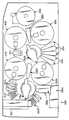
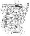
도1은 본 발명에 따른 자동 핵산계 진단 분석기의 사시도이다.1 is a perspective view of an automated nucleic acid-based diagnostic analyzer according to the present invention.
도2는 본 발명의 진단 분석기의 구조적인 프레임의 사시도이다.2 is a perspective view of a structural frame of the diagnostic analyzer of the present invention.
도3은 본 발명의 진단 분석기의 분석 처리 데크(assay processing deck) 부분의 평면도이다.3 is a plan view of an assay processing deck portion of the diagnostic analyzer of the present invention.
도4는 분석 처리 데크의 분해 사시도이다.4 is an exploded perspective view of the analysis treatment deck.
도5는 본 발명의 진단 분석기의 분석 처리 데크의 표본 링(specimen ring)과 피펫 팁 휠(pipette tip wheel)의 평면도이다.5 is a plan view of a specimen ring and a pipette tip wheel of the analytical processing deck of the diagnostic analyzer of the present invention.
도6은 표본 링과 피펫 팁 휠을 보여주는 사시도이다.6 is a perspective view showing a sample ring and a pipette tip wheel.
도6a는 도5의 선6A-6A를 따른 부분적인 단면도이다.6A is a partial cross sectional view along line 6A-6A in FIG.
도7은 본 발명의 진단 분석기의 처리 데크의 다축 믹서의 사시도이다.7 is a perspective view of the multi-axis mixer of the processing deck of the diagnostic analyzer of the present invention.
도8은 다축 믹서의 평면도이다.8 is a plan view of a multi-axis mixer.
도9는 다축 믹서의 측면도이다.9 is a side view of the multi-axis mixer.
도10은 용기 홀더와 턴테이블 커버가 제거된 상태의 다축 믹서의 평면도이다.Fig. 10 is a plan view of the multi-axis mixer with the container holder and turntable cover removed.
도11은 도10의 방향 11-11에서 취한 다축 믹서의 횡단면도이다.FIG. 11 is a cross sectional view of the multi-axis mixer taken in direction 11-11 of FIG.
도12는 다축 믹서의 구동 조립체의 사시도이다.12 is a perspective view of a drive assembly of a multi-axis mixer.
도13은 본 발명의 진단 분석기의 처리 데크의 이송 기구의 사시도이다.Figure 13 is a perspective view of the transfer mechanism of the treatment deck of the diagnostic analyzer of the present invention.
도14는 이송 기구의 조작 후크 장착 플레이트(manipulating hook mounting plate)와 조작 후크 작동 기구의 사시도로서, 조작 후크 부재가 반응 리셉터클에 결합되어 수축된 위치에 있는 상태를 보여 주는 도면이다.Fig. 14 is a perspective view of the manipulating hook mounting plate and the manipulating hook operating mechanism of the transfer mechanism, showing the state in which the manipulating hook member is in a retracted position coupled to the reaction receptacle.
도15는 조작 후크 부재가 연장된 위치에 있는 것을 제외하고는 도14와 동일한 도면이다.Figure 15 is the same view as Figure 14 except that the operating hook member is in the extended position.
도16은 이송 기구의 분해 사시도이다.16 is an exploded perspective view of the transfer mechanism.
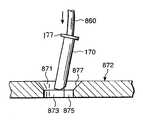
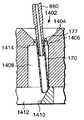
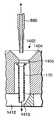
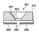
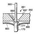
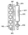
도17은 본 발명의 진단 분석기의 처리 데크의 온도 램핑 스테이션(temperature ramping station)의 측면도이다.Figure 17 is a side view of a temperature ramping station of the treatment deck of the diagnostic analyzer of the present invention.
도18은 온도 램핑 스테이션의 정면도이다.18 is a front view of the temperature ramping station.
도19는 본 발명의 진단 분석기의 처리 데크의 회전 인큐베이터의 사시도이다.Figure 19 is a perspective view of a rotary incubator of the treatment deck of the diagnostic analyzer of the present invention.
도20은 회전 인큐베이터의 제1 실시예에 따른 하우징 및 접근 개구 폐쇄 기구의 일부의 분해 사시도이다.20 is an exploded perspective view of a portion of the housing and access opening closing mechanism according to the first embodiment of the rotary incubator.
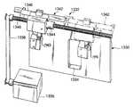
도21은 본 발명의 진단 분석기의 양호한 작동 모드에서 채용된 반응 리셉터클과 맞물린 것을 보여 주는, 회전 인큐베이터의 경사진 디스크 선형 믹서(skewed disk linear mixer)의 부분적인 도면이다.FIG. 21 is a partial view of a skewed disk linear mixer of a rotary incubator showing engagement with a response receptacle employed in the preferred mode of operation of the diagnostic analyzer of the present invention.
도22는 회전 인큐베이터의 제1 실시예의 분해 사시도이다.Figure 22 is an exploded perspective view of the first embodiment of the rotary incubator.
도23은 그의 제2 실시예에 따른 회전 인큐베이터의 사시도이다.Figure 23 is a perspective view of a rotary incubator in accordance with a second embodiment of the same.
도23a는 회전 인큐베이터의 제2 실시예의 분해 사시도이다.Fig. 23A is an exploded perspective view of a second embodiment of a rotary incubator.
도23b는 회전 인큐베이터의 제2 실시예의 접근 개구 폐쇄 기구의 부분적인 분해 사시도이다.Fig. 23B is a partially exploded perspective view of the access opening closing mechanism of the second embodiment of the rotary incubator.
도23c는 회전 인큐베이터의 제2 실시예의 리셉터클 캐리어 캐루셀(receptacle carrier carousel)의 분해도이다.FIG. 23C is an exploded view of the receptacle carrier carousel of the second embodiment of the rotary incubator. FIG.
도24는 그의 측면 플레이트가 제거된 본 발명의 처리 데크의 자기 분리 세척 스테이션의 사시도이다.Figure 24 is a perspective view of the magnetic separation washing station of the treatment deck of the present invention with its side plate removed.
도25는 자기 분리 세척 스테이션의 부분적인 횡단면도이다.25 is a partial cross sectional view of a magnetic separation wash station.
도25a는 오염 제한 팁렛이 그의 단부상에 지지된 자기 분리 세척 스테이션의 흡인 튜브의 팁의 부분적인 횡단면도이다.25A is a partial cross sectional view of the tip of a suction tube of a magnetic separation wash station with a contamination limiting tiplet supported on its end;
도26은 자기 분리 세척 스테이션의 분리기 플레이트, 궤도 믹서 조립체, 및 리셉터클 캐리어 유닛의 분해 사시도이다.Figure 26 is an exploded perspective view of the separator plate, orbital mixer assembly, and receptacle carrier unit of the magnetic separation washing station.
도27은 세척 버퍼 분배기 노즐, 오염 제한 팁렛이 그의 단부에 맞물린 흡인기 튜브, 및 자기 분리 세척 스테이션의 리셉터클 캐리어 유닛의 부분적인 단면도로서, 리셉터클 캐리어 유닛으로 운반된 분석기와 다중 튜브 유닛의 리셉터클 용기에 삽입된 흡인기 튜브와 오염 제한 팁렛의 양호한 작동 모드에 채용된 다중 튜브 유닛 반응 리셉터클을 도시하는 도면이다.FIG. 27 is a partial cross-sectional view of the wash buffer dispenser nozzle, the aspirator tube with the contamination limiting tiplet engaged at its end, and the receptacle carrier unit of the magnetic separation wash station, inserted into the receptacle container of the analyzer and multi-tube unit delivered to the receptacle carrier unit. Is a diagram showing a multi-tube unit reaction receptacle employed in the preferred mode of operation of the aspirator tube and contamination limiting tiplet.
도28은 세척 버퍼 분배기 노즐, 흡인기 튜브, 및 자기 분리 세척 스테이션의 리셉터클 캐리어 유닛의 부분적인 단면도로서, 리셉터클 캐리어 유닛으로 운반된 다중 튜브 유닛 및 다중 튜브 유닛의 오염 제한 부재 지지 구조물에 지지된 오염 제한 팁렛과 맞물리는 흡인기 튜브를 도시하는 도면이다.FIG. 28 is a partial cross-sectional view of the wash buffer dispenser nozzle, the aspirator tube, and the receptacle carrier unit of the magnetic separation washing station, with the contamination restriction supported on the contamination limiting member support structure of the multi tube unit and the multi tube unit carried to the receptacle carrier unit. FIG. A diagram showing an aspirator tube engaged with a tiplet.
도29a 내지 도29d는 자기 분리 세척 스테이션의 팁렛 스트리핑(stripping) 플레이트의 팁렛 스트리핑 구멍과 팁렛 스트리핑 구멍을 이용하는 팁렛 스트리핑 작동의 제1 실시예에 대한 단면도를 도시하는 도면이다.29A-29D show a cross-sectional view of a first embodiment of a tiplet stripping operation utilizing a tiplet stripping hole and a tiplet stripping hole of a tiplet stripping plate of a magnetic separation washing station.
도30a 내지 도30d는 팁렛 스트리핑 구멍 및 팁렛 스트리핑 구멍을 이용하는 팁렛 스트리핑 작동의 제2 실시예의 단면도를 도시하는 도면이다.30A-30D show cross-sectional views of a second embodiment of a tiplet stripping operation utilizing a tiplet stripping hole and a tiplet stripping hole.
도31a는 자기 분리 세척 스테이션의 팁렛 스트리핑 플레이트의 팁렛 스트리핑 구멍의 제3 실시예의 평면도를 도시하는 도면이다.FIG. 31A shows a plan view of a third embodiment of a tiplet stripping hole of a tiplet stripping plate of a magnetic separation washing station. FIG.
도31b 및 도31c는 팁렛 스트리핑 구멍 및 팁렛 스트리핑 구멍을 이용하는 팁렛 스트리핑 작동의 제3 실시예의 횡단면도를 도시하는 도면이다.31B and 31C show a cross-sectional view of a third embodiment of a tiplet stripping operation using a tiplet stripping hole and a tiplet stripping hole.
도32는 그의 전방 플레이트가 제거된 궤도 믹서의 분해도이다.32 is an exploded view of an orbital mixer with its front plate removed.
도33은 본 발명의 진단 분석기의 처리 데크의 궤도 믹서의 분해도를 도시하는 도면이다.Fig. 33 is an exploded view of the orbital mixer of the processing deck of the diagnostic analyzer of the present invention.
도34는 궤도 믹서의 평면도이다.34 is a top view of the orbital mixer.
도35는 본 발명의 진단 분석기의 처리 데크의 시약 냉각 베이(bay)의 상부 사시도이다.Figure 35 is a top perspective view of a reagent cooling bay of the treatment deck of the diagnostic analyzer of the present invention.
도36은 용기 트레이가 그 곳으로부터 제거된 시약 냉각 베이의 상부 사시도이다.36 is a top perspective view of the reagent cooling bay with the vessel tray removed therefrom.
도37은 시약 냉각 베이의 하부 평면도이다.37 is a bottom plan view of a reagent cooling bay.
도38은 시약 냉각 베이의 분해도이다.38 is an exploded view of a reagent cooling bay.
도39는 시약 냉각 베이의 모듈 용기 트레이의 상부 사시도이다.Figure 39 is a top perspective view of a module vessel tray in a reagent cooling bay.
도40은 본 발명의 진단 분석기의 처리 데크의 루미노미터(luminometer)의 제1 실시예의 사시도이다.Figure 40 is a perspective view of a first embodiment of a luminometer of the treatment deck of the diagnostic analyzer of the present invention.
도41은 제1 실시예의 루미노미터의 부분적인 분해 사시도이다.Fig. 41 is a partially exploded perspective view of the luminometer of the first embodiment.
도42a는 루미노미터의 제1 실시예의 리셉터클 이송 기구의 부분적인 사시도 이다.Fig. 42A is a partial perspective view of the receptacle transport mechanism of the first embodiment of the luminometer.
도42b는 루미노미터의 제1 실시예의 리셉터클 이송 기구의 단부도이다.42B is an end view of the receptacle transport mechanism of the first embodiment of the luminometer.
도42c는 루미노미터의 제1 실시예의 리셉터클 이송 기구의 상부도이다.Figure 42C is a top view of the receptacle transport mechanism of the first embodiment of the luminometer.
도43은 본 발명의 루미노미터의 제2 실시예의 절단 사시도이다.Figure 43 is a cutaway perspective view of a second embodiment of the luminometer of the present invention.
도44는 제2 실시예의 루미노미터의 다중 튜브 유닛 도어 조립체의 분해 사시도이다.Figure 44 is an exploded perspective view of the multi-tube unit door assembly of the luminometer of the second embodiment.
도45는 제2 실시예의 루미노미터의 광 센서 구멍에 대한 셔터 조립체의 분해 사시도이다.Figure 45 is an exploded perspective view of the shutter assembly for the optical sensor hole of the luminometer of the second embodiment.
도45a는 제2 실시예의 루미노미터의 셔터 조립체의 구멍 플레이트의 사시도이다.45A is a perspective view of a hole plate of the shutter assembly of the luminometer of the second embodiment.
도46은 리셉터클 용기 포지셔너 프레임(receptacle vessel positioner frame)내에 배치된 리셉터클 용기 포지셔너를 포함하는, 제2 실시예의 루미노미터의 리셉터클 용기 포지셔너 조립체의 사시도이다.Figure 46 is a perspective view of the receptacle vessel positioner assembly of the luminometer of the second embodiment, including a receptacle vessel positioner disposed within the receptacle vessel positioner frame.
도47은 리셉터클 용기 포지셔너의 사시도이다.47 is a perspective view of the receptacle container positioner.
도48은 리셉터클 용기 포지셔너 조립체의 측면도이다.48 is a side view of the receptacle container positioner assembly.
도49는 진단 분석기의 양호한 작동 모드에 채용된 다중 튜브 유닛과 작동가능하게 맞물리는 리셉터클 용기 포지셔너 조립체의 리셉터클 용기 포지셔너를 도시하는 사시도이다.FIG. 49 is a perspective view illustrating the receptacle container positioner of the receptacle container positioner assembly operatively engaged with the multiple tube unit employed in the good mode of operation of the diagnostic analyzer.
도50은 제2 실시예의 루미노미터의 다중 튜브 유닛 이송 기구의 사시도이다.50 is a perspective view of a multi-tube unit transport mechanism of the luminometer of the second embodiment.
도51은 루미노미터의 다중 튜브 유닛 이송 기구의 다중 튜브 유닛 이송 및 구동 스크류를 도시하는 부분적인 사시도이다.Fig. 51 is a partial perspective view showing the multi-tube unit feed and drive screw of the multi-tube unit feed mechanism of the luminometer.
도52는 본 발명의 진단 분석기의 하부 섀시의 사시도이다.Figure 52 is a perspective view of the lower chassis of the diagnostic analyzer of the present invention.
도53은 하부 섀시의 우측 서랍의 사시도이다.53 is a perspective view of the right drawer of the lower chassis.
도54는 하부 섀시의 좌측 서랍의 사시도이다.54 is a perspective view of the left side drawer of the lower chassis.
도55는 본 발명의 진단 분석기의 양호한 작동 모드에 채용된 표본 튜브 트레이의 사시도이다.Figure 55 is a perspective view of a sample tube tray employed in the preferred mode of operation of the diagnostic analyzer of the present invention.
도56은 표본 튜브 트레이의 평면도이다.56 is a top view of a sample tube tray.
도57은 도55의 선57-57을 통한 표본 튜브 트레이의 부분적인 단면도이다.FIG. 57 is a partial cross-sectional view of the sample tube tray through line 57-57 of FIG. 55;
도58은 본 발명의 진단 분석기의 양호한 작동 모드에 채용된 다중 튜브 유닛의 사시도이다.58 is a perspective view of a multiple tube unit employed in the preferred mode of operation of the diagnostic analyzer of the present invention.
도59는 본 발명의 진단 분석기의 양호한 작동 모드에 채용되고 도58에 도시된 다중 튜브 유닛상에서 운반된 접촉 제한 피펫 팁렛의 측면도이다.Figure 59 is a side view of the contact limiting pipette tiplet employed in the preferred mode of operation of the diagnostic analyzer of the present invention and carried on the multiple tube unit shown in Figure 58;
도60은 도58에서 화살표 60의 방향에서 본 다중 튜브 유닛의 일부분의 확대된 하부도이다.FIG. 60 is an enlarged bottom view of a portion of the multitube unit seen in the direction of
본 발명에 따른 자동 진단 분석기는 도1 및 도2에서 전체적으로 참조부호 50으로 도시되어 있다. 분석기(50)는 양호하게는 스틸로 만들어진 내부 프레임 구조(62)위에 조립된 하우징(60)을 포함한다. 분석기(50)는 양호하게는 분석기를 이동시킬 수 있도록 프레임 구조물(62)에 구조적으로 장착된 다리 바퀴(64)상에 지지된다.The automated diagnostic analyzer according to the present invention is shown generally at 50 in FIGS. 1 and 2. The
자동 분석을 수행하는데 수반된 다양한 스테이션과 분석 표본이 하우징(60)내에 수용된다. 또한, 분석을 수행하는데 사용된 다양한 용액, 시약, 및 다른 재료는 분석기(50)에서 분석이 수행될 때 발생된 폐기물로서 양호하게는 하우징(60)내에 저장된다.Various stations and analytical specimens involved in performing the automated analysis are housed in the
하우징(60)은 도1에 도시된 테스트 리셉터클 적재 개구(68)를 포함하는데, 이 개구(68)는 하우징(60)의 전방으로 향한 패널에 배치되지만, 하우징(60)의 다른 패널에 위치될 수도 있다. 관찰 창(72)을 가지는 피펫 도어(70)와 관찰 창(76)을 가지는 캐루셀 도어(74)는 전체적으로 수평한 작업면(66)위에 배치되어 있다. 전방으로 돌출한 아치형 패널(78)은 이하에서 설명되는 표본 캐루셀(specimen carousel)을 수용한다. 플립업식(flip-up) 아치형 표본 도어(80)는 아치형 패널(78)에 대해 수직방향으로 피벗하도록 하우징에 피벗가능하게 부착되어서 패널(78)의 뒤에 있는 표본 캐루셀의 전방 부분에 대한 접근을 제공할 수 있게 한다. 센서는 도어가 폐쇄될 때를 나타내며, 표본 도어(80), 캐루셀 도어(74), 및 피펫 도어(70)는 분석기의 작동 중에 잠겨진다. 각각의 도어에 대한 잠금 기구는 양호하게는 스프링 복귀에 의해 (연속적인 효율로 등급이 매겨진) DC 회전 솔레노이드에 부착된 후크로 이루어진다. 양호한 회전 솔레노이드는 미국, 오하이오, 반달리아 소재의 루카스 컨트롤 시스템즈의 제품번호 L-2670-034 및 L-1094-034로부터 입수할 수 있다.The
양호하게는 투명 또는 반투명한 재료로 만들어진 연장 부분(102)은 하우징(60)내에서 부품들을 이동시키기 위한 수직방향의 틈새를 제공하도록 하우징(60)의 상부에서 위쪽으로 연장한다.The extending
분석은 주로 아래에서 설명되는 분석기(50)의 여러 분석 스테이션의 일반적인 위치인 처리 데크(200)상에서 수행된다. 도시의 단순화를 위해, 처리 데크(200)는 도2에 임의의 분석 스테이션이 그 위에 장착되지 않은 상태로 도시되어 있다. 처리 데크(200)는 여러 스테이션이 직접 또는 간접적으로 장착되는 기준 플레이트(82)를 구비한다. 기준 플레이트(82)는 양호하게는 기계 가공된 알루미늄 플레이트를 구비한다. 또한, 화학 데크(chemistry deck)로 알려진 처리 데크(200)는 하우징의 내부를 기준 플레이트(82)의 상부의 화학 영역, 또는 상부 섀시와 기준 플레이트(82)의 아래에 위치된 저장 영역, 또는 하부 섀시(1100)로 분리한다.The analysis is primarily performed on the
상부 섀시의 전체에 대해 공기 순환을 일으켜서 상부 섀시에서 과도한 온도가 발생되는 것을 피하도록 하기 위해 양호하게는 다수의 팬 및 루버(louver)가 하우징(60)의 상부 섀시부에 제공된다.A number of fans and louvers are preferably provided in the upper chassis portion of the
본 발명의 분석기(50)가 컴퓨터로 제어될 때, 분석기(50)는 도2에서 박스(1000)로 도식적으로 나타낸 컴퓨터 제어기를 포함하는데, 이 컴퓨터 제어기는 "분석 관리 프로그램"으로서 알려진 고수준의 분석기-제어 소프트웨어를 가동시킨다. 분석 관리 프로그램은 화학 데크(200)를 통해 테스트 표본의 움직임을 감시 및 제어하는 스케쥴 루틴(schedule routine)을 포함한다.When the
분석기(50)를 제어하는 컴퓨터 제어기(1000)는 CPU, 키보드, 모니터를 포함하는 독립하여 조작이 가능한 컴퓨터 시스템을 포함할 수 있고, 선택적으로 프린터 장치를 포함할 수 있다. 휴대용 카트가 또한 여러 컴퓨터 부품들을 저장 및 지지하기 위해 제공될 수 있다. 대안으로, 분석기 제어 소프트웨어를 가동시키기 위한 컴퓨터 하드웨어가 분석기(50)의 하우징(60)내에 일체로 수용될 수 있다.
용적 유체(bulk fluid) 및 폐기 유체 용기내의 유체 높이를 감시하고 분석기(50)에 사용된 전기 모터 및 히터의 제어와 같은 저수준의 분석기 제어는 양호하게는 모토롤라 68332 마이크로프로세서를 구비하는 내장식 제어기에 의해 수행된다. 분석기에 사용된 스텝핑 모터(stepper motor) 역시 양호하게는 미국, 펜실베니아, 바라 신위드 소재의 이-엠 테크롤러지스로부터 입수할 수 있는 미리 프로그램된, 기성품인 마이크로프로세서 칩에 의해 제어된다.The
Low-level analyzer control, such as monitoring the fluid level in the bulk fluid and waste fluid containers and controlling the electric motors and heaters used in the
처리 데크(200)는 도3 및 도4에 도식적으로 도시되어 있다. 도3은 처리 데크(200)의 일부의 도식적인 평면도이고, 도4는 처리 데크의 도식적인 사시도이다. 기준 플레이트(82)는 모든 스테이션들이 직접 또는 간접적으로 부착되는 처리 데크(200)의 바닥부를 형성한다.The
처리 데크(200)는 하우징(60)의 전방에 있는 구멍(68)으로부터 연장하는 반응 리셉터클 투입 열(150)을 포함한다. 다수의 반응 리셉터클들은 투입 열(150)내에 스택된 형태로 적재된다. 투입 열의 목적은 정해진 수의 반응 리셉터클들을 지지하여 이들을 이송 기구(아래에서 설명됨)에 의해 회수된 픽업 위치로 연속적으로 제공하기 위한 것이다. 픽업 위치에 있는 반사 센서는 그 위치에 리셉터클의 존재를 확인한다. 투입 열은 또한 임의의 정해진 시간에 그 안에 존재하는 리셉터클의 수를 계산하기 위한 장치를 포함한다.The
상기 열내의 반응 리셉터클 셔틀 조립체(도시되지 않음)는 픽업 위치를 향해 리셉터클 진행 경로를 따라 리셉터클을 이동시킨다. 광 센서는 셔틀 조립체가 그 홈 및 완전 연장된 위치에 있는 때를 지시한다. 상기 열은 그 안에 리셉터클을 적재하기 위해 인출될 수 있는 서랍 부재를 포함한다. 그러나, 서랍 부재가 개방되기 전에, 상기 서랍 부재는 잠금 해제되어야 하고 셔틀은 리셉터클 진행 경로로부터 해제되어야 한다. 서랍 부재가 다시 폐쇄될 때, 상기 서랍 부재는 잠금되고 셔틀은 리셉터클을 결합하여 이들을 픽업 위치를 향하여 이동시킨다. 광 센서는 서랍부재가 폐쇄된 때 및 셔틀이 리셉터클을 결합한 때를 지시한다. 각각의 리셉터클이 이송 기구에 의해 픽업 위치로부터 제거되면, 리셉터클 셔틀은 하나의 리셉터클 폭만큼 리셉터클을 전진시키며, 따라서 다음 리셉터클이 픽업 위치로 오게 된다.A reaction receptacle shuttle assembly (not shown) in the column moves the receptacle along the receptacle travel path towards the pick up position. The light sensor indicates when the shuttle assembly is in its groove and in a fully extended position. The row includes a drawer member that can be drawn out to load the receptacle therein. However, before the drawer member is opened, the drawer member must be unlocked and the shuttle must be released from the receptacle travel path. When the drawer member is closed again, the drawer member is locked and the shuttle engages the receptacles to move them towards the pick-up position. The light sensor indicates when the drawer member is closed and when the shuttle engages the receptacle. As each receptacle is removed from the pick-up position by the transfer mechanism, the receptacle shuttle advances the receptacle by one receptacle width, thus bringing the next receptacle to the pick-up position.
반응 리셉터클은 양호하게는 테스트 튜브의 일체로 형성된 직선 배열이며 다중 튜브 유닛 또는 MTUs 로 알려져 있다. 양호한 반응 리셉터클(MTUs)은 아래에서 더욱 상세히 기술될 것이다.The reaction receptacle is preferably an integrally formed straight array of test tubes and is known as multi-tube units or MTUs. Preferred reaction receptacles (MTUs) will be described in more detail below.
양호한 실시예에서 표본 링(250)을 구비하는 제1 링 조립체는 기준 플레이트(82)의 위의 소정의 거리에서 피벗식 지그 플레이트(130)상에 장착된다. 표본 링(250)은 일반적으로 원형이고 양호하게는 환상의 유체 용기 캐리어 부분내에 9개까지의 표본 트레이(300)를 지지하며, 표본 트레이의 각각은 양호하게는 20개의 표본 수용 용기 또는 테스트 튜브(320)를 보유한다. 표본 링(250)은 일반적으로 수직한 회전축에 대해 회전할 수 있도록 구성 및 배열되며 표본 튜브(320)를 표본 피펫 조립체(450), 양호하게는 자동화 로봇 피펫 시스템으로 전달한다. 표본 링(250)의 전방 부분은 테스트 튜브(320)의 트레이(300)가 용이하게 표본 링(250)상에 적재되고 표본 링으로부터 적하될 수 있도록 하우징(60)에 제공된 플립업식 캐루셀 도어(80)를 통해 접근이 가능하다. 표본 링(250)은 아래에 더욱 상세히 기술되는 바와 같이, 모터에 의해 구동된다.In a preferred embodiment the first ring assembly with
양호한 실시예에서 피펫 팁 휠(350)을 구비하는 제2 링 조립체는 표본 링(250)의 내부에 위치되며, 따라서 피펫 팁 휠(350)의 외측 주연부의 적어도 일부분이 링(250)의 내측 표면에서 반경 내측 방향으로 배치된다. 피펫 팁 휠(350)은 그 위에 상업적으로 입수할 수 있는 다수의 피펫 팁 패키지를 지지하고 있다. 피펫 팁 휠(350)은 표본 링(250)의 제1 회전축에 대해 일반적으로 평행한 제2 회전축에 대해 표본 링(250)과 독립적으로 회전하도록 모터 구동된다.In a preferred embodiment the second ring assembly with the
다수의 유체 용기를 지지하도록 구성 및 배열된 내부의 회전 가능한 조립체는 피펫 팁 휠(350)의 내부에 제공된다. 양호한 실시예에서, 내부의 회전 가능한 조립체는 피펫 팁 휠(350, 즉, 제2 링 조립체)과 표본 링(250, 즉, 제1 링 조립체)의 내측에 반경방향으로 위치된 다중축 믹서(400)를 구비한다. 다중축 믹서(400)는 제1 및 제2 회전축에 대해 일반적으로 평행한 제3 회전축에 대해 회전할 수 있고 독립적으로 그리고 편심적으로 회전하는 4개의 용기 홀더(406)가 그 위에 장착되는 회전 턴테이블(414)을 포함한다. 용기 홀더(406)의 각각은 양호하게는 부동화된 폴리뉴클레오티드 및 폴리뉴클레오티드 캡쳐 탐침(capture probe)을 갖는 자기 입자의 유체 부유물을 함유하는 플라스틱 병의 형태로 된 용기를 수용한다. 각각의 용기 홀더(406)는 일반적으로 원통형의 형상이며 대칭축 또는 회전축을 포함한다. 다중축 믹서(400)는 홀더(406)의 중심에 대해 용기의 각각을 편심적으로 회전시키며, 자기 입자를 유체내에서 부유물로 유지하기 위해 용기를 실질적으로 일정하게 교반하도록 턴테이블(414)을 그 중심에 대해 동시에 회전시킨다.An internal rotatable assembly constructed and arranged to support a plurality of fluid containers is provided inside the
표본 피펫 조립체 또는 로봇(450)은 표본 링(250)과 피펫 팁 휠(350)의 상부의 위치에서 프레임 구조물(62, 도2 참조)에 장착된다. 표본 피펫 조립체(450)는 X, Y, Z 운동을 제공하기 위해 갠트리 조립체(gantry assembly)상에 장착된 관형 탐침(457)을 가지는 피펫 유닛(456)을 포함한다. 구체적으로, 피펫 유닛(456)은 측면 레일(454)에 형성된 트랙(458)을 따라 Y방향으로 선형 이동할 수 있고, 측면 레일(454)은 길이방향 트랙(452)을 따라 X방향으로 길이방향 이동할 수 있다. 피펫 유닛(456)은 탐침(457)의 수직 또는 Z축 운동을 제공한다. 표본 피펫 조립체(450)내의 구동 기구는, 유체를 피펫으로 옮기거나, 피펫 유닛(456)의 탐침(457)을 세척하거나, 피펫 유닛(456)의 탐침(457)의 단부로부터 보호용 팁을 폐기하거나, 또는 피펫 유닛(456)을 사용하지 않는 기간중에 예컨대 "홈" 위치에 채워넣기 위해, 피펫 유닛(456)을 분석기(50)내의 정확한 X, Y, Z 좌표로 위치 설정한다. 표본 피펫 조립체(450)의 각각의 축은 공지된 종래의 방식으로 스텝핑 모터에 의해 구동된다.The sample pipette assembly or
피펫 조립체는 양호하게는 기성품이다. 현재 양호한 제품으로는 미국, 캘리포니아, 써니베일 소재의 카브로사로부터 입수할 수 있는 모델 번호 RSP9000인 로봇 샘플 처리 장치가 있다. 이 모델은 단일 갠트리 암을 포함한다.The pipette assembly is preferably ready-made. A good product at present is a robotic sample processing device of model number RSP9000 available from Cabros, Sunnyvale, California. This model includes a single gantry arm.
표본 피펫 조립체(450)는 양호하게는 주입기 펌프(도시되지 않음, Cavro XP 3000이 사용됨)와 DC 피동 다이아프램 시스템 유체 세척 펌프(도시되지 않음)에 결합된다. 표본 피펫 조립체(450)의 주입기 펌프는 양호하게는 화학 데크(200)의 좌측 상부의 위치에서 분석기(50)의 하우징(60)내의 내부 프레임 구조물(62)에 장착되어 적합한 배관(도시되지 않음) 또는 다른 도관 구조물에 의해 피펫 유닛(456)에 연결된다.The
표본 준비 개구(252)는 표본 피펫 조립체(450)가 지그 플레이트(130)의 아래에 위치된 투입 열(150)내의 반응 리셉터클(160)에 접근할 수 있도록 지그 플레이트(130)에 제공된다.The
분석기(50)의 표본 피펫 조립체(450)는 상승된 커버 플레이트(138)의 개구(140, 142)를 통해 표본 링(250)상에 지지된 표본 튜브(320)와 결합하고 표본 링(250)의 후방 위치 부근의 피펫 팁 휠(350)상에 지지된 피펫 팁 및 피펫 팁 휠(350)과 각각 결합한다. 따라서, 작동자는 피펫으로 옮기는 절차를 방해하지 않고 분석기의 작동 중 캐루셀 도어 개구(80)를 통해 표본 링(250)과 피펫 팁 휠(350)의 전방 위치에 접근할 수 있다.The
팁 세척/폐기 스테이션(340)은 지그 플레이트(130)상의 표본 링(250)에 인접하게 배치된다. 스테이션(340)은 팁 폐기 튜브(342)와 세척 스테이션 베이슨(basin, 346)을 포함한다. 표본의 준비 중에, 표본 피펫 조립체(450)의 피펫 유닛(456)은 세척 스테이션 베이슨(346)의 상부의 위치로 이동할 수 있고, 여기서 관형 탐침(457)은 탐침(457)을 통해 증류수를 펌핑함으로써 세척될 수 있고, 세척 스테이션 베이슨(346)은 양호하게는 가요성 호스(도시되지 않음)에 의해 하부 섀시(1100)의 액체 폐기 용기에 연결된다.Tip cleaning /
팁 폐기 튜브(342)는 직립한 관형 부재를 구비한다. 표본 튜브(320)로부터 반응 리셉터클(160)로 표본을 이송하는 동안, 긴 피펫 팁은 피펫 유닛(456)의 관형 탐침(457)의 단부상에 마찰에 의해 고정되어, 표본 재료는 재료가 표본 튜브(320)로부터 긴 피펫 팁으로 끌어당겨질 때 피펫 유닛(456)의 관형 탐침(457)과 접촉하지 않게 된다. 표본이 표본 튜브(320)로부터 이송된 후, 이 표본을 이송하는데 사용된 피펫 팁이 관련없는 다른 표본에 대해 다시 사용되지 않는 것이 중요하다. 그러므로, 표본이 이송된 후, 피펫 유닛(456)은 팁 폐기 튜브(342)의 상부의 위치로 이동하여 사용이 이루어진 폐기 가능한 피펫 팁을 하부 섀시(1100) 내에 지지된 고체 폐기 용기들 중의 하나에 연결되어 있는 팁 폐기 튜브(342) 내로 배출한다.
긴 피펫 팁은 양호하게는 다중축 믹서(400)상에 지지된 용기로부터 반응 리셉터클(160)로 타겟 캡쳐 시약을 이송하기 위한 탐침(457)에 마찰식으로 또한 고정된다. 시약을 이송한 다음, 피펫 팁은 폐기된다.The long pipette tip is preferably also frictionally secured to the probe 457 for transferring the target capture reagent from the vessel supported on the
기술된 바와 같이, 표본 링(250), 피펫 팁 휠(350), 및 다중축 믹서(400)는 양호하게는 기준 플레이트(82)위에 지지된 힌지 결합된 지그 플레이트(130, 도5 및 도6 참조)상에 장착된다. 지그 플레이트(130)는 플레이트, 링(250), 휠(350), 및 그 위에 장착된 믹서(400)가 지그 플레이트의 아래에 있는 화학 데크의 영역에 대한 접근을 허용하기 위해 상향으로 피벗될 수 있도록 그의 후방 단부(132, 도6 참조)에서 힌지 결합된다.
제1 또는 우측 이송 기구(500)는 투입 열(150)과 일반적으로 같은 평면상에서 지그 플레이트(130)와 표본 링(250)의 아래에 있는 기준 플레이트(82)상에 장착된다. 이송 기구(500)는 리셉터클 캐리어 조립체를 형성하는 회전 가능한 주 본체(504) 및 주 본체(504)내에 장착되고 동력을 갖춘 후크 부재 구동 조립체에 의해 연장 및 수축 가능한 연장형 조작 후크(506)를 포함한다. 반응 리셉터클(160)의 각각은 양호하게는 연장 가능한 조작 후크(506)에 의해 결합될 수 있는 조작 구조를 포함하며, 따라서 이송 기구(500)는 반응 리셉터클(160)을 결합 및 조작하여, 반응 리셉터클(160)내에서 분석이 수행되는 동안 반응 리셉터클이 한 스테이션에서 다른 스테이션으로 연속적으로 이동될 때 이를 처리 데크(200)상의 한 위치로부터 다른 위치로 이동시킬 수 있다.As described, the
The first or
또한, 제1 분배 암(500)과 실제로 동일한 구조의 제2 이송 기구 또는 좌측 이송 기구(502)는 처리 데크(200)상에 포함된다.In addition, a second transfer mechanism or
복수의 리셉터클 파킹 스테이션(receptacle parking station, 210)이 또한 지그 플레이트(130)의 아래에 위치된다. 파킹 스테이션(210)은, 그의 명칭에서 알 수 있는 바와 같이, 분석기(50)의 처리 데크(200)의 분석 수행 스테이션이 반응 리셉터클을 받아들일 준비가 될 때까지 표본을 수용하는 반응 리셉터클을 보유하기 위한 구조이다. 반응 리셉터클은 이송 기구(500)에 의해 필요한 만큼 파킹 스테이션(210)으로부터 회수되고 또한 이에 삽입된다.A plurality of
우측의 궤도 믹서(550)는 기준 플레이트(82)에 부착되어 우측의 이송 기구(500)에 의해 삽입된 반응 리셉터클(160)을 수용한다. 궤도 믹서는 반응 리셉터클(160)의 내용물을 혼합하기 위해 제공된다. 혼합이 완료된 후, 우측의 이송 기구(500)는 우측의 궤도 믹서(550)로부터 반응 리셉터클을 제거하여 처리 데크내의 다른 위치로 이동시킨다.The
실제로 구성이 동일한 다수의 인큐베이터(600, 602, 604, 606)가 제공된다. 인큐베이터(600, 602, 604, 606)는 양호하게는 회전식 인큐베이터이다. 수행될 특별한 분석 및 원하는 처리량이 필요로 하는 인큐베이터의 원하는 수를 결정하지만, 양호하게는 4개의 인큐베이터가 분석기(50)에 제공된다.In fact, a number of
이하에서 더욱 상세히 기술되는 바와 같이, 각각의 인큐베이터(600, 602, 604, 606)는 제1 및 제2 리셉터클 접근 개구를 가질 수 있고, 이를 통해 이송 기구(500 또는 502)는 반응 리셉터클(160)을 인큐베이터 안으로 삽입하거나 또는 반응 리셉터클(160)을 인큐베이터로부터 회수할 수 있다. 각각의 인큐베이터(600, 602, 604, 606)내에는 리셉터클이 인큐베이션(incubation)되는 동안 각각의 리셉터클 스테이션내에 복수의 반응 리셉터클(160)을 보유하는 회전 리셉터클 캐리어 캐루셀이 배치된다. 본 발명의 분석기(50)상에서 양호하게 수행되는 핵산계 진단 분석을 위해, 제1 회전식 인큐베이터(600)는 타겟 캡쳐 및 어닐링(annealing) 인큐베이터이고, 제2 회전식 인큐베이터(602)는 활성 온도 및 미리 판독된 냉각(cool-down) 인큐베이터("AT 인큐베이터"로 공지됨)이고, 제3 회전식 인큐베이터(604)는 증폭 인큐베이터이며, 제4 회전식 인큐베이터(606)는 하이브리드화 보호 분석 인큐베이터이다. 분석의 전체적인 수행에 있어서의 인큐베이터의 구성, 기능 및 역할은 이하에서 더욱 상세히 기술될 것이다.As described in more detail below, each
처리 데크(200)는 양호하게는 복수의 온도 램핑 스테이션(700)을 포함한다. 두 개의 이러한 스테이션(700)이 인큐베이터(602, 604) 사이에서 기준 플레이트(82)에 부착된 것으로 도3에 도시되어 있다. 추가적인 램핑 스테이션은 이송 기구(500, 502)들 중의 하나에 의해 접근이 가능한 처리 데크(200)상의 다른 위치에 배치될 수 있다.The
반응 리셉터클(160)은 이송 기구(500, 502)에 의해 온도 램핑 스테이션(700)의 안으로 배치되거나 또는 이로부터 제거될 수 있다. 각각의 램핑 스테이션(700)은 반응 리셉터클과 그 내용물의 온도를 리셉터클이 인큐베이터 또는 다른 온도 감응성 스테이션 내로 배치되기 전에 원하는 온도로 상승 또는 하강시킨다. 반응 리셉터클과 그 내용물을 인큐베이터(600, 602, 604, 606) 중 하나에 삽입하기 전에 원하는 온도에 이르게 함으로써, 인큐베이터 내의 온도 변화가 최소화된다.The
처리 데크(200)는 또한 자기 분리 세척 절차를 수행하기 위한 자기 분리 세척 스테이션(800)을 포함한다. 각각의 자기 분리 세척 스테이션(800)은 한번에 하나의 반응 리셉터클(160)에 대한 세척 절차를 수용하여 수행할 수 있다. 그러므로, 원하는 처리량을 성취하기 위해, 평행하게 작동하는 5개의 자기 분리 세척 스테이션(800)이 양호하다. 리셉터클(160)은 좌측의 이송 기구(502)에 의해 자기 분리 세척 스테이션(800)에 삽입되고 또 이로부터 제거된다.The
시약 냉각 베이(reagent cooling bay, 900)는 인큐베이터(604, 606)사이에서 기준 플레이트(82)에 대략 부착되어 있다. 시약 냉각 베이(900)는 온도 감음성 시약의 병을 보유하기 위한 복수의 용기 리셉터클을 가지는 캐루셀 구조를 구비한다. 캐루셀은 피펫 접근 구멍이 그 내부에 형성된 뚜껑을 가지는 냉각된 하우징 구조내에 위치한다.A
우측의 궤도 믹서(550)와 실제로 동일한 제2의 믹서 또는 좌측의 궤도 믹서(552)는 인큐베이터(606, 604)사이에 배치된다. 좌측의 궤도 믹서(552)는 좌측의 궤도 믹서(552)내에 위치한 반응 리셉터클의 안으로 유체를 분배하기 위한 라인 및 분배기 노즐을 포함한다.A second mixer, or the left
시약 피펫 조립체 또는 로봇(470)은 프레임 구조물(62, 도2 참조)에 부착된 이중 갠트리 구조물을 포함하며, 처리 데크(200)의 좌측에 있는 인큐베이터(604, 606)의 대략 위에 배치된다. 구체적으로, 시약 피펫 조립체(470)는 피펫 유닛(480, 482)을 포함한다. 피펫 유닛(480)은 관형 탐침(481)을 포함하고, 측면 레일(476)의 트랙(474)을 따라 일반적으로 X방향으로 선형 이동을 하도록 장착되며, 관형 탐침(483)을 포함하는 피펫 유닛(482) 역시 측면 레일(478)의 트랙(484)을 따라 일반적으로 X방향으로 선형 이동을 하도록 장착된다. 측면 레일(476, 478)은 길이방향의 트랙(472)을 따라 일반적으로 Y방향으로 병진 이동할 수 있다. 각각의 피펫 유닛(480, 482)은 각각의 탐침(481, 483)의 독립적인 수직 운동, 또는 Z축 운동을 제공한다. 조립체(470)내의 구동 기구는, 유체를 피펫으로 옮기거나, 각각의 피펫 유닛(480, 482)의 관형 탐침(481, 483)을 세척하거나, 또는 피펫 유닛(480, 482)을 사용하지 않는 기간중에 예컨대 "홈" 위치에 채워넣기 위해, 피펫 유닛(480, 482)을 분석기(50)내의 정확한 X, Y, Z 좌표로 위치 설정한다. 피펫 조립체(470)의 각각의 축은 스텝핑 모터에 의해 구동된다.The reagent pipette assembly or
시약 피펫 조립체(470)는 양호하게는 기성품이다. 현재 양호한 유닛은 2개의 갠트리 아암을 갖는 모델 RSP9000의 카브로 로봇 샘플 처리 장치이다.The
시약 피펫 조립체(470)의 피펫 유닛(480, 482)은 각각 양호하게는 각각의 주입기 펌프(도시되지 않음, 카브로 XP 3000이 사용되어 왔다)와 DC 피동 다이아프램 시스템 유체 세척 펌프에 결합되어 있다. 시약 피펫 조립체(470)의 주입기 펌프는 양호하게는 화학 데크(200)의 좌측의 상부 위치에서 분석기(50)의 하우징(60)내의 내부 프레임 구조물(62)에 장착되어 적합한 배관(도시되지 않음) 또는 다른 도관 구조물에 의해 각각의 피펫 유닛(480, 482)에 연결된다.The
각각의 피펫 유닛(480, 482)은 양호하게는 용량 수준 감지 능력을 포함한다. 의료 기기 기술분야에서 일반적으로 알려져 있는 용량 수준 감지 기능은 피펫 유닛의 탐침이 용기내의 유체에 침투했을 때를 감지하기 위해 피펫 유닛에 의해 콘덴서의 한 플레이트로서 형성된 콘덴서의 유전체와 피펫 유닛에 의해 대향하는 플레이트로서 결합된 용기를 에워싸는 구조물 및 하드웨어가 공기에서 유체로 변할 때 용량 변화를 채용한다. 피펫 유닛의 수직 이동을 구동하는 스텝핑 모터를 감시함으로써 알 수 있는 피펫 유닛의 탐침의 수직 위치를 확인함으로써, 피펫 유닛에 의해 결합된 용기내의 유체의 수준이 결정될 수 있다.Each
피펫 유닛(480)은 시약을 시약 냉각 베이(900)로부터 인큐베이터(606) 또는 궤도 믹서(552)내에 배치된 반응 리셉터클 내로 옮기며, 피펫 유닛(482)은 시약 재료를 시약 냉각 베이(900)로부터 증폭 인큐베이터(604) 또는 궤도 믹서(552)내에 배치된 반응 리셉터클 내로 옮긴다.
피펫 유닛(480, 482)은 용기내의 유체 수준을 확인하고 피펫 유닛의 탐침의 단부의 작은 일부분만 잠기게 하여 용기로부터 유체를 피펫으로 옮기기 위해 용량 수준 감지 기능을 사용한다. 피펫 유닛(480, 482)은 양호하게는 탐침의 단부를 일정한 깊이까지 잠기게 하기 위해 유체가 각각의 관형 탐침(481, 483)안으로 피펫 이동될 때 내려간다. 시약을 피펫 유닛(480 또는 482)의 관형 탐침 내로 끌어당긴 후, 피펫 유닛은 화학 데크(200)위의 다른 위치로 피펫 유닛이 이동될 때 탐침의 단부로부터 한 방울이라도 떨어지지 않게 하기 위해 각각의 탐침(481 또는 483)의 단부에 10μl의 최소 공기 이동 갭을 형성한다.The
본 발명의 분석기(50)에서 양호하게 수행된 분석의 결과는 적절한 준비 단계의 끝에서 리셉터클 용기(162)로부터 방출된 화학 발광 또는 빛의 량에 의해 확인된다. 구체적으로, 분석의 결과는 분석의 끝에서 하이브리드화된 폴리뉴클레오티드 탐침과 관련된 라벨에 의해 방출된 빛의 량으로부터 결정된다. 따라서, 처리 데크(200)는 반응 리셉터클의 내용물에 의해 방출된 빛의 량을 검출 및/또는 정량화하기 위한 루미노미터(luminometer, 950)를 포함한다. 간단히 말하면, 루미노미터(950)는 이송 기구, 광전자증배관 튜브(photomultiplier tube), 및 관련된 전자기술의 영향하에서 반응 리셉터클이 이동하는 하우징을 구비한다. 다양한 루미노미터 실시예가 아래에서 상세히 기술될 것이다.The results of the well performed analysis in the
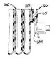
처리 데크(200)는 또한 양호하게는 비활성화 열(deactivation queue, 750)을 포함한다. 분석기(50)에서 수행된 분석은 관심의 적어도 하나의 유기체 또는 세포에 속하는 핵산의 격리 및 증폭을 수반한다. 그러므로, 분석의 끝에서 일반적으로 탈색 염기 시약을 반응 리셉터클(160)속으로 분배함으로써 반응 리셉터클(160)의 내용물을 비활성화하는 것이 바람직하다. 이러한 비활성화는 비활성화 열(750)내에서 일어난다.The
비활성화 다음에, 반응 리셉터클(160)의 비활성화된 내용물은 하부 섀시(1100)의 액체 폐기 용기 중 하나에 저장되고 사용된 반응 리셉터클은 하부 섀시(1100)내의 전용 고체 폐기 용기속으로 폐기된다. 반응 리셉터클은 양호하게는 재사용되지 않는다.Following deactivation, the deactivated contents of the
분석기의 작동Operation of the Analyzer
분석기(50)의 작동, 및 상술된 스테이션, 구성 부품 및 모듈의 구성, 협동 및 상호 작용은 분석기(50)로 수행될 수 있는 분석의 한 형태의 수행에서 단일 테스트 표본에 대한 분석기(50)의 작동을 기술함으로써 설명될 것이다. 본원에 기술된 하나 이상의 스테이션, 구성 부품 및 모듈의 사용을 필요로 하는 다른 진단 분석도 역시 분석기(50)로 수행될 수 있다. 여기서 행한 특별한 분석 절차의 설명은 분석기(50)의 여러 스테이션, 구성 부품 및 모듈의 작동 및 상호 작용을 설명하기 위한 것에 불과하며 이에 제한될 필요는 없다. 진단 테스트 기술 분야에 숙련된 당업자들은 다양한 화학적 및 생물학적 분석이 본 발명의 분석기(50)로 자동화 형태로 수행될 수 있다는 것을 인식할 것이다.The operation of the
분석기(50)는 초기에 용적 유체를 하부 섀시(1100)의 용적 유체 저장 베이로 적재하여 용적 유체 용기를 적절한 호스(도시되지 않음)에 연결함으로써 분석을 수행하도록 구성된다.The
분석기는 양호하게는 연속적인 공정으로 동력 공급되며, 초기에 그 공정에서 필요로 하는 스테이션 또는 모듈에 동력을 공급하고, 이어서 그 공정에서 나중까지 필요로 하지 않는 스테이션에 동력을 공급한다. 이는 에너지를 보존하는 역할을 하고, 또한 전체 분석기에 대한 동력 공급을 수반하고 회로 차단기를 트립(trip)시킬 수 있는 큰 서지 전압을 피하게 한다. 분석기는 또한 사용하지 않는 기간중에 "슬립"(sleep) 모드를 채용한다. 슬립 모드 중에, 완전 차단 상태로부터 분석기에 동력을 공급하는데 필요한 큰 서지 전압을 피하기 위해 다시 최소량의 동력이 분석기로 공급된다.The analyzer is preferably powered in a continuous process, initially powering the station or module needed by the process and then powering the station that is not needed later in the process. This serves to conserve energy and also avoids large surge voltages that can involve powering the entire analyzer and trip the circuit breaker. The analyzer also employs a "sleep" mode during periods of inactivity. During sleep mode, a minimum amount of power is again supplied to the analyzer to avoid the large surge voltage needed to power the analyzer from a full shutdown.
아래에서 더욱 상세히 설명되는, 양호하게는 플라스틱으로 일체로 형성된 다중-튜브 유닛(MTUs)의 형태로 된 다수의 반응 리셉터클(160)은 구멍(68)을 통해 투입 열(150)에 적재된다. 이제부터 반응 리셉터클(160)은 분석기(50)를 사용하는 양호한 방식에 부합되는 MTUs 로서 언급될 것이다.A plurality of
투입 열(150)내의 반응 리셉터클 셔틀 조립체(도시되지 않음)는 적재 구멍(68)으로부터 투입 열(150)의 단부에 있는 픽업 위치까지 MTUs(160)를 이동시킨다. 우측의 이송 기구(500)는 투입 열(150)의 단부로부터 MTU(160)를 취해서 이 MTU를 확인하는 이 MTU상의 고유한 바 코드 라벨을 판독하기 위해 바 코드 판독기(253)로 이동시킨다. 바 코드 판독기(253)로부터, MTU는 개구(252)의 아래에 있는 사용 가능한 표본 이송 스테이션(255)으로 이동된다.A reaction receptacle shuttle assembly (not shown) in the
다중 튜브 유닛Multi-tube unit
도58에 도시된 바와 같이, MTU(160)는 복수의 개개의 리셉터클 용기(162), 양호하게는 5개의 리셉터클 용기(162)를 구비한다. 양호하게는 상단부가 개방되고 하단부가 폐쇄된 원통형 튜브의 형태로 된 리셉터클 용기(162)는 MTU(160)의 양 측면을 따라 길이 방향으로 연장하는 하향의 견부를 형성하는 연결 리브 구조(164)에 의해 서로 연결된다.As shown in FIG. 58, the
MTU(160)는 양호하게는 사출 성형된 폴리프로필렌으로부터 형성된다. 가장 양호한 폴리프로필렌은 미국, 델라웨어, 윌밍턴 소재의 몬텔 폴리올레핀(Montell Polyolefins)에 의해 판매되는 제품 번호 PD701NW 이다. 몬텔 재료는 분석기(50)의 양호한 작동 모드로 쉽게 성형가능하고, 화학적으로 적합하기 때문에 사용되며, 정밀한 검출 또는 화학 발광 현상의 정량화를 방해할 수 있는 한정된 수의 정전 방전 현상을 갖는다.
아치형의 실드 구조물(169)이 MTU(160)의 일단부에 제공된다. 이송 기구(500, 502)의 하나에 의해 결합되는 MTU 조작 구조(166)는 실드 구조물(169)로부터 연장한다. MTU 조작 구조물(166)은 플레이트(168)의 대향 단부상에 수직으로 연장하는 피스(167)를 갖는 실드 구조물(169)로부터 연장하는 측면 연장 플레이트(168)를 구비한다. 이음판 벽(165)은 실드 구조물(169)과 수직 피스(167)사이에서 측면 플레이트(168)로부터 하향으로 연장한다.An
도60에 도시된 바와 같이, 실드 구조물(169)과 수직 피스(167)는 상호 대향하는 볼록한 표면을 가진다. MTU(160)는 실드 구조물(169)과 수직 피스(167)사이의 공간 내로 결합 부재를 측면 방향으로 ("A"방향으로) 이동시킴으로써, 아래에 기술되는 바와 같이, 이송 기구(500, 502)와 다른 구성 부품에 의해 결합된다. 실드 구조물(169)과 수직 피스(167)의 볼록한 표면은 공간속으로 측면 방향의 상대 운동을 하는 결합 부재에 대해 보다 넓은 입구의 지점을 제공한다. 수직 피스(167)와 실드 구조물(169)의 볼록한 표면은 그의 중앙 부분에 각각 형성된 융기 부분(171, 172)을 포함한다. 융기 부분(171, 172)의 목적은 아래에서 기술될 것이다.As shown in FIG. 60,
평평한 라벨 수용 표면(175)을 가지는 라벨 수용 구조물(174)은 실드 구조물(169)과 MTU 조작 구조물(166)에 대향한 MTU(160)의 일단부상에 제공된다. 스캔 가능한 바 코드와 같은 그러한 라벨은 MTU(160)상에 확인 및 지시 정보를 제공하기 위해 표면(175)상에 배치될 수 있다.A
MTU(160)는 양호하게는 각각의 리셉터클 용기(162)의 개방 구멍에 인접한 팁렛(tiplet) 지지 구조물(176)을 포함한다. 각각의 팁렛 지지 구조물(176)은 접촉 제한 팁렛(contact-limiting tiplet, 170)이 수용되는 원통형 오리피스를 제공한다. 팁렛(170)의 구조 및 기능은 아래에서 기술될 것이다. 각각의 지지 구조물(176)은 MTU(160)가 뒤집힐 때 팁렛(170)이 지지 구조물(176)로부터 떨어져 나오는 것을 방지하지만, 피펫에 의해 결합될 때 팁렛(170)이 지지 구조물(176)로부터 제거되는 것을 허용하는 방식으로 팁렛(170)을 마찰식으로 수용하도록 구성 및 배열된다.
도59에 도시된 바와 같이, 팁렛(170)은 팁렛(170)의 하부 부분(179)보다 일반적으로 직경이 더 큰 상부 칼라(collar, 178)와 외주연 림 플랜지(177)를 가지는 일반적으로 원통형 구조를 구비한다. 팁렛(170)은 양호하게는 전도성 폴리프로필렌으로 형성된다. 팁렛(170)이 지지 구조물(176)의 오리피스 내로 삽입될 때, 플랜지(177)는 구조물(176)의 상부와 접촉하고, 칼라(178)는 팁렛(170)과 지지 구조물(176) 사이에 부드럽지만 해제 가능한 억지 끼워 맞춤을 제공한다.As shown in Figure 59, the
축방향으로 연장하는 관통 구멍(180)이 팁렛을 통과한다. 구멍(180)은 피펫 관형 탐침(도시되지 않음)을 팁렛(170) 내로 삽입하는 것을 용이하게 하는 팁렛(170)의 상부에 있는 외향으로 벌어진 단부(181)를 포함한다. 두 개의 환형의 릿지(183)가 구멍(180)의 내벽에 정렬된다. 릿지(183)는 팁렛(170)과 팁렛(170)에 삽입된 관형 탐침 사이에 마찰 억지 끼워 맞춤을 제공한다.An axially extending through
팁렛(170)의 바닥은 양호하게는 경사면부(182)를 포함한다. 팁렛(170)이 MTU(160)의 리셉터클 용기(162)와 같은 반응 리셉터클의 바닥에 삽입되는 흡인기의 단부상에 사용될 때, 경사면부(182)는 팁렛(170)의 단부와 반응 리셉터클 용기의 바닥 사이에 진공이 형성되는 것을 방지한다.The bottom of the
하부 섀시Lower chassis
본 발명의 하부 섀시의 실시예가 도52 내지 도54에 도시되어 있다. 하부 섀시(1100)는 블랙 폴리우레탄 분말 코팅(black polyurethane powder coat)을 갖는 스틸 프레임(1101), 섀시의 아래에 배치된 풀-아웃 드립 트레이(pull-out drip tray, 1102), 우측의 서랍(1104), 및 좌측의 서랍(1106)을 포함한다. 좌측의 서랍(1106)은 하부 섀시(1100) 내의 사실상 중앙에 배치된다. 하부 섀시(1100)의 먼 좌측에는, 예컨대, 장착 플랫폼(1154)상에 장착된 7개의 주입기 펌프(1152), 진동 절연 장치(도시되지 않음)상의 하부 섀시(1100)의 플로어상에 양호하게 장착된 진공 펌프(1162), 동력 공급 유닛(1156), 동력 필터(1158), 및 팬(1160)과 같은 여러 동력 공급 시스템 부품들 및 다른 분석기 기구들이 내장된다.Embodiments of the lower chassis of the invention are shown in FIGS. 52-54. The
5개의 자기 분리 세척 스테이션(800)의 각각에 대해 다른 주입기 펌프(1152)가 지정되며, 하나는 좌측 궤도 믹서(552)에 대해 지정되고, 하나는 비활성화 열(750)에 대해 지정된다. 주입기 펌프가 양호하지만, 연동 펌프가 대안으로 사용될 수 있다.For each of the five magnetic separation wash stations 800 a
진공 펌프(1162)는 자기 분리 세척 스테이션(800)과 비활성화 열(750)의 각각에 대해 작용한다. 진공 펌프의 양호한 정격(rating)은 0"Hg에서 5.3 내지 6.5cfm이고 5"Hg에서 4.2 내지 5.2cfm이다. 양호한 진공 펌프는 미국 위스콘신, 쉐보이건 소재의 토마스 인더스트리즈사로부터 모델 번호 2750CGHI60 으로서 입수할 수 있다. 콘덴서(1172)는 펌프(1162)와 함께 판매된다.
동력 공급 유닛(1156)은 양호하게는 미국, 캘리포니아, 칼스배드 소재의 ASTEC 아메리카사로부터 입수할 수 있는 ASTEC, 모델 번호 VS1-B5-B7-03 이다. 동력 공급 유닛(1156)은 50 내지 60Hz 범위의 220 볼트, 즉 전형적인 220 볼트 벽 콘센트로부터 나오는 동력을 사용할 수 있다. 동력 필터(1158)는 양호하게는 미국, 일리노이스, 리버티빌 소재의 코콤사로부터 입수할 수 있는 코콤 모델 20MV1 필터이다. 팬(1160)은 양호하게는 미국, 캘리포니아, 산 이시드로 소재의 코메이어 로트론으로부터 입수할 수 있는 휘스퍼 XLDC 팬이다. 각각의 팬은 24VDC 모터에 의해 동력을 공급받으며 75 cfm 출력을 가진다. 도52에 도시된 바와 같이, 팬(1160)은 양호하게는 하부 섀시(1100)의 좌측 외측 벽 근처에 배치된다. 팬(1160)은 양호하게는 그의 우측으로부터 그의 좌측으로 하부 섀시를 통해 공기를 끌어 당겨서, 하부 섀시의 외부로 과도한 열을 배출시키도록 아래로 향하여 배치된다.The
다른 동력 공급 시스템 부품들은 동력 스위치(1174), 양호하게는 미국, 오하이오, 클리버랜드 소재의 이턴 코포레이션의 커틀러-햄머 디비젼으로부터 입수할 수 있는 이턴 회로 차단기 스위치 2-극, 직렬 JA/S, 및 분석기(50)를 외부 동력원에 연결하기 위한 동력 코드(도시되지 않음)가 연결되는 동력 입구 모듈(1176)을 포함하여, 하부 섀시(1100)의 후방 좌측에 내장된다. 분석기(50)의 동력 공급 시스템은 또한 다수의 전기 단자를 부착하기 위한 단자 블록(도시되지 않음), 상이한 회로들 사이에서 전환하기 위해 양호하게는 미국, 캘리포니아, 카슨 시티 소재의 칼 스위치로부터 입수 가능한 크리덤 시리즈 1, 모델 번호 D2425 인 고체 상태 스위치(도시되지 않음), 및 분석기(50)를 외부 컴퓨터 제어기(1000)에 연결하기 위한 RS232 9-핀 연결 포트를 포함한다.Other power supply system components include a
우측 서랍 베이와 좌측 서랍 베이는 양호하게는 분석기의 작동 중에 분석 관리 프로그램에 의해 양호하게 로크되는 분석기의 전방에서 하나 또는 두 개의 도어(도시되지 않음)의 뒤쪽에서 폐쇄된다. 마이크로스위치는 양호하게는 도어 폐쇄 상태를 확인하기 위해 제공된다. 먼 좌측 베이는 전방 패널에 의해 덮인다. 단부 패널은 섀시를 둘러싸기 위해 하부 섀시의 대향 단부상에 제공된다.The right drawer bay and the left drawer bay are preferably closed at the back of one or two doors (not shown) in front of the analyzer which are preferably locked by the analysis management program during operation of the analyzer. The microswitch is preferably provided for checking the door closed state. The far left bay is covered by the front panel. End panels are provided on opposite ends of the lower chassis to enclose the chassis.
4개의 수평 조절 다리(leveler foot)(1180)는 섀시(1100)의 4개의 모퉁이로부터 아래로 연장한다. 높이 조절 다리(1180)는 그의 하부 단부에 패드를 갖는 나사 가공된 샤프트를 포함한다. 분석기가 원하는 위치에 있을 때, 높이 조절 다리(1180)는 분석기를 높이 조절하여 안정시키기 위해 패드가 바닥과 결합할 때까지 낮추어 질 수 있다. 수평 조절 다리는 또한 분석기가 그의 캐스터상에서 이동되도록 하기 위해 상승될 수 있다.Four
일반적으로 하부 섀시(1100)의 용기에 포함된 용적 유체는 (부동화된 타겟을 세척하기 위한) 세척 버퍼, (고정된 피펫 팁을 세척하기 위한) 증류수, 진단 테스트 시약, (테스트 시약과 표본 위에 층을 이루는 부유 유체로서 사용된) 실리콘 오일, 및 (샘플 비활성화를 위해 사용된) 탈색제 계열 시약을 포함할 수 있다.In general, the volumetric fluid contained in the vessel of the
우측 서랍(1104)이 도53에 상세히 도시되어 있다. 우측 서랍(1104)은 전방 서랍 손잡이(1105)를 갖는 박스형 서랍 구조를 포함한다. 분석기(50)의 양호한 실시예에서 서랍 손잡이(1105)가 종래의 당김 형태의 서랍 손잡이로 도시되어 있지만, 손잡이(1105)는 미국, 펜실베니아, 콘코드빌 소재의 사우스코사로부터 입수할 수 있는 것과 같은 T-손잡이 래치이다. 서랍(1104)은 서랍(1104)이 하부 섀시의 내부로 그리고 외부로 당겨질 수 있도록 활주 브래킷(도시되지 않음)상에서 하부 섀시에 장착된다. 센서(도시되지 않음)는 양호하게는 서랍(1104)이 폐쇄되는 것을 확인하기 위해 제공된다. 서랍의 전방 부분은 전용 피펫 세척 폐기물을 함유하는 병인 보틀(1128, 도52에 도시됨)과, 자기 세척, 타겟-캡쳐 처리로부터 나오는 폐기물을 함유하는 전용 폐기물 병인 보틀(1130, 도52에 도시됨)을 보유하기 위한 보틀 리셉터클(1122)을 포함한다. 보틀(1130)은 양호하게는 소기되어 있다.
분석기(50)는 하부 섀시(1100)에서 요구되는 보틀 중 어느 하나라도 없다면, 처리 분석을 개시하지 않는다. 보틀 리셉터클(1122)은 양호하게는 각각의 리셉터클(1122)내의 보틀의 존재를 확인하기 위해 보틀-존재 센서(도시되지 않음)를 포함한다. 보틀-존재 센서는 양호하게는 미국, 아이오와, 웨스트 데스 모인스 소재의 SUNX/Ramco 일렉트릭사로부터 입수할 수 있는 확산 반사형 광 센서인 모델 EX14A 이다.The
우측의 서랍(1104)은 또한 사용된 MTUs 와 표본 팁을 그곳에 보유하기 위한 폐기물 저장소(1108)를 포함한다. 폐기물 저장소(1108)는 폐기물 저장소(1108)가 가득 차 있는지를 검출하기 위한 센서, 양호하게는 24VDC 광확산 반사기 스위치(Opto-diffuse reflector switch, 도시되지 않음)를 그 위에 장착하기 위해 그 곳의 상부 부분에 센서 장착부(1112)를 갖는 개방된 박스 구조물의 형태를 이루고 있다. 또 다른 확산 반사기 형태의 광 센서(도시되지 않음)가 폐기물 저장소(1108)가 제 위치에 있는지를 확인하기 위해 우측 서랍(1104)내에 위치되어 있다. 마찬가지로, 미국, 아이오와, 웨스트 데스 모인스 소재의 SUNX/Ramco 일렉트릭사로부터 입수할 수 있는 확산 반사 형태의 광 센서, 모델 EX14A 가 양호하다.The
편향기(deflector, 1110)는 폐기물 저장소(1108)의 측면으로부터 비스듬하게 연장한다. 편향기(1110)는 슈트(chute)의 바로 아래에 배치되며, 상기 슈트를 통해 사용된 MTUs가 폐기물 저장소(1108) 안으로 낙하되고 폐기물 저장소(1108)의 모서리에 MTUs가 쌓이는 것을 피하기 위해 MTUs를 폐기물 저장소(1108)의 중간을 향해 편향시킨다. 편향기(1110)는 양호하게는 폐기물 저장소(1108)를 정렬시키고 편향기(1110)를 덮는 폐기물 백이 폐기물 저장소(1108)로부터 제거될 때, 편향기(1110)가 끌어당겨 질 때 백과 함께 상향으로 피벗하여 백을 찢지 못하도록 실제로 수직 위치로 상향으로 피벗할 수 있도록 피벗 가능하게 장착된다.
인쇄 회로 기판(도시되지 않음)과 커버(1114)는 폐기물 저장소(1108)의 전방에 장착될 수 있다. 센서 장착부(1116, 1117)는 또한 폐기물 저장소(1108)의 전방에 장착된다. 센서(1118, 1119)는 센서 장착부(1116)상에 장착되고, 센서(1120, 1121)는 센서 장착부(1117)상에 장착된다. 센서(1118, 1119, 1120, 1121)는 양호하게는 DC 용량 프록시미티 센서(proximity sensor)이다. 상부 센서(1118, 1119)는 보틀(1128, 1130)이 가득 차 있을 때를 가리키며, 바닥 센서(1120, 1121)는 보틀이 비어 있을 때를 가리킨다. 센서(1118 내지 1121)는 양호하게는 미국, 네바다, 레노 소재의 스테드햄 일렉트로닉스 코포레이션으로부터 입수할 수 있는 모델 번호 C2D45AN1-P 이며, 이는 이들의 비교적 편평한 물리적인 외형이 하부 섀시(1100)의 조밀한 범위내에 더 적은 공간을 요하며 스테드햄의 센서가 3 내지 20mm의 원하는 감지 거리 범위를 제공하기 때문에 선택되었다.The printed circuit board (not shown) and
분석기(50)는 양호하게는 분석 관리 프로그램이 우측 서랍(1104)내의 폐기물 유체 용기들 중 어느 하나라도 초기에 비어 있지 않은 것을 검출하는 경우 분석을 수행하지 않을 것이다.The
우측 서랍(1104)의 용량 프록시미티 센서(1118-1121)와 보틀-존재, 폐기물 저장소의 존재, 및 폐기물 저장소 가득참 광 센서는 커버(1114) 뒤의 인쇄 회로 기판(도시되지 않음)에 접속되고, 인쇄 회로 기판은 분석기(50)의 내장된 제어기에 접속된다.Capacitive proximity sensors 1118-1121 and bottle-existence of the
우측 서랍(1104)이 하부 섀시(1100)의 외부로 완전히 당겨질 수 없기 때문에, 폐기물 백 라이너를 설치 및 제거하기 위해 폐기물 저장소에 접근할 수 있도록 폐기물 저장소(1108)를 전방으로 당길 수 있는 것이 필요하다. 이 목적을 위해, 손잡이(1126)는 폐기물 저장소(1108)의 전방에 장착되고 테프론 스트립(1124)은 보틀(1128, 1130)이 제거될 때 서랍(1104)내에서 폐기물 저장소(1108)의 전후방 미끄럼을 용이하게 하기 위해 우측 서랍(1104)의 바닥면상에 배치된다.Since the
좌측 서랍(1106)의 상세한 구성은 도54에 도시되어 있다. 좌측 서랍(1106)은 전방에 장착된 손잡이(1107)를 갖는 박스형 구조물을 포함하며 하부 섀시(1100)내에서 활주 브래킷(도시되지 않음)상에 장착된다. 손잡이(1107)가 분석기(50)의 양호한 실시예에서 종래의 당김 형태의 서랍 손잡이로서 도시되어 있지만, 손잡이(1107)는 미국, 펜실베니아, 콘코드빌 소재의 사우스코사로부터 입수할 수 있는 그러한 T-손잡이 래치이다. 센서는 좌측 서랍(1106)이 폐쇄되는 것을 확인하기 위해 제공된다.A detailed configuration of the
좌측 서랍(1106)은 팁렛 폐기물 저장소 가득참 센서(도시되지 않음)를 그 위에 장착하기 위한 장착 구조물(1135)을 갖는 팁렛 폐기물 저장소(1134)를 포함한다. 팁렛 폐기물 저장소 존재 센서는 양호하게는 팁렛 폐기물 저장소(1134)가 적절하게 설치되어 있는 것을 확인하기 위해 좌측 서랍(1106)에 제공된다. 미국, 오와이오, 웨스트 데스 모인스 소재의 SUNX/Ramco 일렉트릭사로부터 입수할 수 있는 확산 반사형 광 센서, 모델 EX14A 가 팁렛 폐기물 저장소 가득참 센서와 팁렛 폐기물 저장소 존재 센서 양쪽에 대해 바람직하다.
하부 섀시(1100)내의 여러 배관 및/또는 와이어(도시되지 않음)를 고정 및 묶기 위해 번들 구조물(bundling structure, 1132)이 제공된다. 양호하게 사용된 번들 구조물(1132)은 로데 아일런드, 이스트 프로빈스의 이구스사에 의해 제조 및 판매된 에너지 체인 시스템이다.A
인쇄 회로 기판(1182)은 팁렛 폐기물 저장소(1134)의 뒤에 위치되어 있는 패널(1184)의 뒤에 장착된다. 솔레노이드 밸브 장착 패널(1186)은 팁렛 폐기물 저장소(1134)의 아래에 위치된다.The printed
좌측 서랍(1106)은 6개의 유사한 크기의 보틀들을 보유하기 위한 전방 용기 보유 구조물을 포함한다. 용기 구조물은 칸막이 벽(1153, 1155, 1157, 1159)과 6개의 용기 보유 영역을 함께 형성하는 보틀의 형상에 일치하는 만곡된 전방 가장자리를 가지는 용기 브래킷(1151)을 포함한다. 하부 센서(1148)와 상부 센서(1150, 각각 6개)는 칸막이 벽(1155, 1157, 1159)상에 장착된다. 상부 및 하부 센서(1148, 1150)는 양호하게는 DC 용량 프록시미티 센서(양호하게는 그들의 편평한 외형 및 감지 범위에 대해 선택된, 미국, 네바다, 레노 소재의 스테드햄 일렉트로닉스 코포레이션으로부터 입수할 수 있는 센서, 모델 번호 C2D45AN1-P)이다. 상부 센서(1150)는 용기 구조물내에 보유된 보틀이 가득 차 있을 때를 표시하며, 하부 센서(1148)는 보틀이 비어 있을 때를 표시한다. 양호한 실시예에서, 2개의 좌측 보틀(1146)은 검출 약제("검출 I")를 수용하고, 2개의 중간 보틀(1168)은 실리콘 오일을 수용하고, 2개의 우측 보틀(1170)은 또 다른 검출 약제("검출 II")를 수용한다.
보틀 존재 센서(도시되지 않음)는 양호하게는 각각의 용기 보유 영역내의 보틀의 존재를 확인하기 위해 용기 블록(1151)과 칸막이 벽(1153, 1155, 1157, 1159)에 의해 형성된 용기 보유 영역의 각각에 제공된다. 보틀 존재 센서는 양호하게는 미국, 아이오와, 웨스트 데스 모인스 소재의 SUNX/Ramco 일렉트릭사로부터 입수할 수 있는 확산 반사형 광 센서, 모델 EX14A 이다.Bottle presence sensors (not shown) preferably each of the container retention areas formed by
중앙에 위치된 큰 용기 리셉터클(1164)은 양호하게는 탈이온화된 물을 함유하는 보틀(1140, 도52에 도시됨)이다. 용기 리셉터클(1166, 도54에서 하나만 도시됨)은 양호하게는 세척 버퍼 용액을 함유하는 보틀(1142, 1144)을 보유한다. 리셉터클(1164, 1166)사이의 칸막이 벽(1143)은 보틀(1140, 1142, 1144)내의 유체 높이를 감시하기 위해 센서(1141)와 같은 그러한 센서들을 그 위에 장착했다. 센서(1141)와 같은 그러한 센서는 양호하게는 DC 용량 프록시미티 센서(양호하게는, 미국, 네바다, 레노 소재의 스테드햄 일렉트로닉스 코포레이션으로부터 입수할 수 있는 센서, 모델 번호 C2D45AN1-P)이다.The centrally placed
용기 리셉터클(1164, 1166)은 양호하게는 보틀이 그 각각의 리셉터클내에 적절히 위치된 것을 확인하기 위한 보틀 존재 센서(도시되지 않음)를 포함한다. 보틀 존재 센서는 양호하게는 미국, 아이오와, 웨스트 데스 모인스 소재의 SUNX/Ramco 일렉트릭사로부터 입수할 수 있는 확산 반사형 광 센서, 모델 EX14A 이다.The
분석기(50)는 분석 관리 프로그램이 좌측 서랍(1106)내의 용적 유체 용기들중의 어느 하나가 초기에 비어 있는 것을 결정한다면 어떤 분석도 수행하지 않을 것이다.The
용량 프록시미티 유체 수준 센서, 다양한 보틀 존재 센서, 팁렛 폐기물 저장소 풀 센서, 및 팁렛 폐기물 저장소 존재 센서는 모두 인쇄 회로 기판(1182)에 접속되며, 인쇄 회로 기판(1182)은 분석기(50)의 내장된 제어기에 접속된다.The capacitive proximity fluid level sensor, various bottle presence sensors, tiplet waste reservoir pool sensor, and tiplet waste reservoir presence sensor are all connected to the printed
솔레노이드 밸브 장착 패널(1186)의 아래에는 4개의 솔레노이드 밸브(도시되지 않음)가 장착된다. 솔레노이드 밸브는 유체가 여러 쌍의 보틀들, 즉 세척 버퍼 용액을 수용하는 보틀(1140, 1142), "검출 I" 약제를 수용하는 2개의 보틀(1146), 오일을 수용하는 2개의 보틀(1168), 및 "검출 II" 약제를 수용하는 2개의 보틀(1170)내에 저장되는 용적 유체 보틀들을 연결한다. 각각의 용량형 프록시미티 센서로부터의 신호에 반응하여 솔레노이드 밸브는 같은 유체를 수용하는 2개의 보틀들 중의 하나가 비어 있을 때 같은 유체가 들어있는 다른 보틀으로 대체한다. 부가적으로, 솔레노이드 밸브는 예정된 수의 테스트가 수행된 후 보틀들을 대체할 수 있다. 양호한 솔레노이드 밸브는 미국, 캘리포니아, 라구나 힐스의 베코 매뉴팩쳐링 캄파니사로부터 입수할 수 있는 테프론 솔레노이드 밸브, 모델 번호 S313W2DFRT 및 M223W2DFRLT 이다. 2개의 상이한 모델 번호는 2개의 상이한 튜브 치수에 사용하기에 적합한 솔레노이드 밸브에 대응한다. 테프론 솔레노이드 밸브는 이들이 밸브를 통해 흐르는 유체를 더 적게 오염시키고 밸브가 이들을 통해 흐르는 부식 유체에 의해 손상을 받지 않기 때문에 적합하다.Four solenoid valves (not shown) are mounted below the solenoid
보틀(1136, 도52 참조)은 진공 트랩 브래킷(1137)에 지지된 진공 트랩이고, 보틀(1138)은 탈색 억제 시약과 같은 그러한 비활성화 약제를 수용한다. 다시, 보틀 존재 센서는 양호하게는 보틀(1136, 1138)의 존재를 확인하기 위해 제공된다.Bottle 1136 (see FIG. 52) is a vacuum trap supported on
휴대용 바 코드 스캐너(1190)는 하부 섀시(1100)에서 스캔 가능한 용기 라벨상에 제공된 정보를 스캔하여 분석 관리 프로그램으로 제공할 수 있다. 스캐너(1190)는 코드에 의해 좌측 서랍(1106)의 인쇄 회로 기판(1182)에 접속되고, 양호하게는 칸막이 벽(1143)상에 장착된 브래킷(도시되지 않음)상에 보관된다. 미국, 뉴욕, 홀츠빌 소재의 심볼 테크롤로지스사로부터 입수할 수 있는 스캐너, 시리즈 LS2100 이 바람직하다.The portable
표본 링 및 표본 트레이Specimen ring and specimen tray
표본은 표본 튜브(320)내에 포함되고, 튜브(320)는 분석기(50)의 외측에 있는 튜브 트레이(300)속으로 적재된다. 표본 튜브(320)를 나르는 트레이(300)는 플립업식 캐루셀 도어(80)를 개방함으로써 제공된 접근 개구를 통해 표본 링(250)상에 배치된다.The specimen is contained within the
도5 및 도6을 참조하면, 제1 링 조립체 또는 표본 링(250)은 압착 가공되고 경화되지 않은 알루미늄으로 형성되고 홈통(251)을 통해 연장하는 다수의 돌출된 반경 방향 연장하는 칸막이(254)를 갖는 링(250)의 외주연 주위에 환형 홈통(251)을 형성하는 융기된 링 구조를 포함한다. 양호하게는 9개의 칸막이(254)가 홈통(251)을 9개의 아치형 표본 튜브 트레이 수용 웰부(256)로 나눈다. 홈통(251)과 웰부(256)는 아래에서 기술되는 바와 같이 다수의 용기를 운반하도록 구성 및 배열된 환상의 유체 용기 캐리어부를 형성한다.5 and 6, the first ring assembly or
표본 링(250)은 양호하게는 링(250)이 제1 중앙 회전축에 대해 회전할 수 있도록 도5 및 도6에 도시된 바와 같이 링(250)의 내측 주연부상에 형성된 연속한 V형 릿지(262)와 결합하는 3개의 120°간격의 V형 홈 롤러(257, 258, 260)에 의해 회전 가능하게 지지된다. 롤러는 양호하게는 미국, 캘리포니아, 피츠버그 소재의 비숍-위서카버 코포레이션에 의해 만들어진 모델 번호 W1SSX 이다. 롤러(257, 260)는 고정된 샤프트상에 회전가능하게 장착되며, 롤러(258)는 수직 축을 중심으로 피벗하는 브래킷상에 장착되고 링(250)의 내측 주연부에 대해 반경 외측방향으로 롤러(258)를 가압하도록 스프링 편향된다. 2개의 고정된 롤러와 하나의 반경방향으로 이동가능한 롤러를 갖는 것은 이들 3개의 롤러가 링(250)의 외측이 둥근 내측 주연부를 수용하게 한다. 부가적으로, 링(250)은 연속한 V형 릿지(262)를 고정된 V형 홈 롤러(257, 260)로부터 해제시키기 위해 표본 링(250)이 측방향으로 이동할 수 있도록 피벗 롤러(258)를 단순히 반경 내측 방향으로 가압함으로써 쉽게 설치 및 제거될 수 있다.
표본 링(250)은 가이드 롤러(266, 268)위에서 링(250)의 외측 주연부의 주위를 연장하는 연속 벨트(270, 양호하게는 미국, 뉴욕, 뉴 하이드 파크 소재의 SDP/SI 로부터 입수할 수 있는 모델 번호 A6R3M444080)를 거쳐 스텝핑 모터(264, 일본 도쿄 소재의 오리엔탈 모터 캄파니 리미티드로부터 입수할 수 있는 VEXTA 스텝핑 모터, 모델 번호 PK266-01A가 바람직함)에 의해 구동된다. 홈 센서(home sensor)와 섹터 센서(도시되지 않음), 양호하게는 슬롯형 광 센서(slotted optical sensor)가 표본 튜브 트레이 수용 웰부(256)의 하나에 대응하는 위치에서 회전 홈 위치(home position)에서 링(250)에 인접하게 위치된다. 링(250)은 휠상의 홈 위치에 위치된 홈 플래그(home flag, 도시되지 않음)와 9개의 표본 튜브 트레이 수용 웰부(256)의 각각의 위치에 대응하는 9개의 균일하게 이격된 섹터 플래그(도시되지 않음)를 포함한다. 홈 플래그와 섹터 플래그는 홈 센서와 섹터 센서와 상호 작용하여 링 위치 정보를 분석 관리 프로그램에 제공하고 링(250)을 제어하여 피펫 유닛(450)에 의해 사용자가 재적재 및 접근할 수 있도록 지정된 좌표에 대응하는 9개의 불연속 위치에서 정지한다. 홈 센서와 섹터 센서에 대한 양호한 센서는 미국, 텍사스, 캐롤턴 소재의 옵테크로 부터 입수할 수 있는 옵테크 슬롯 광 센서, 모델 번호 OPB857 이다.The
The
표본 커버는 환상의 유체 용기 캐리어 위치 또는 홈통(251)의 일부분 위에 배치되며, 3개의 장착 포스트(136)상에서 휠(250)에 관해 상승된 위치에 고정된 아치형 커버 플레이트(138)를 구비한다. 플레이트(138)는 홈통(251)의 곡면과 일반적으로 일치하는 아치형 형상을 가진다. 제1 개구(142)는 플레이트(138)에 형성되고, 제2 개구(140)는 개구(142)보다 링(250)의 회전축으로부터 더 크게 반경 방향으로 이격되어 개구(142)로부터 원주방향으로 이격된 위치에서 플레이트(138)에 형성된다.The specimen cover is disposed above the annular fluid container carrier position or a portion of the
도55 내지 도57을 참조하면, 각각의 표본 튜브 트레이(300)는 링(250)의 곡률과 일치하도록 만곡된 테스트 튜브 랙 구조물을 구비한다. 각각의 트레이(300)는 벽(304)의 어느 일단부상에 배치된 측방향 단부 벽(303, 305)을 갖는 중앙 벽 구조물(304)을 구비한다. 바닥(312)은 트레이(300)의 하부를 가로질러 연장한다. 표본 튜브 트레이(300)의 주목적은 표본 피펫 조립체(450)에 의해 접근하기 위한 표본 링(250)상에 표본 튜브를 지지하고 분석기의 안으로 그리고 분석기로부터 다수의 표본 튜브의 적재 및 적하를 용이하게 하기 위한 것이다.55-57, each
다수의 Y형 칸막이(302)는 트레이(300)의 대향한 가장자리를 따라 등거리로 이격된다. 2개의 인접한 각각의 칸막이(302)는 테스트 튜브 수용 영역(330)을 형성한다. 단부 벽(303)은 내측 방향으로 굽혀진 플랜지(316, 318)를 포함하며, 단부 벽(305)은 내측 방향으로 굽혀진 플랜지(326, 328)를 포함한다. 칸막이(302)의 최단부와 함께 단부 벽(303, 305)의 내측 방향으로 굽혀진 플랜지는 최단부 튜브 수용 영역(332)을 형성한다. 수용 영역(330, 332)은 중앙 벽 구조물(304)의 대향 측면상의 두 개의 아치형 열을 따라 아치형으로 정렬된다.The plurality of Y-shaped
도57을 참조하면, 각각의 튜브 수용 영역(330, 332)내에, 리프 스프링 부재(310)가 중앙 벽(304)에 부착된다. 스테인레스 스프링 스틸로 양호하게 형성된 리프 스프링 부재(310)는 테스트 튜브(320)가 튜브 수용 영역(330 또는 332)속으로 삽입되어 튜브(320)를 칸막이(302)에 대해 외측방향으로 가압할 때 탄성적으로 편향한다. 따라서, 튜브(320)는 수직 배향으로 고정된다. 칸막이(302)의 형상과 리프 스프링 부재(310)의 탄성은 트레이(300)가 튜브(320, 324)와 같은 그러한 여러 형상 및 크기의 표본 튜브를 수용하게 한다. 각각의 트레이(300)는 양호하게는 트레이당 총 20개의 튜브 수용 영역(330, 332)을 위해 중앙 벽 구조물(304)의 각 측면상에 단부 벽(303, 305)과 함께 10개의 튜브 수용 영역(330, 332)을 형성하도록 각 가장자리를 따라 9개의 칸막이(302)를 포함한다. 융기된 부호(306)와 같은 그러한 튜브 수용 영역(330, 332)을 지정하기 위한 표시는 중앙 벽(304)과 같은 그러한 트레이상에 제공될 수 있다.Referring to Figure 57, in each
각 트레이(300)는 또한 최단부 칸막이(302)에 일체로 형성될 예시적인 실시예로 도시된 보스 구조물(308)을 포함할 수 있다. 수직하게 반전된 U-형 손잡이(도시되지 않음)는 보스 구조물(308) 또는 다소 다른 적합한 위치에서 트레이에 부착될 수 있다. 수직한 손잡이는 아치형 캐루셀 도어(80)를 통해 트레이(300)를 적재 및 적하할 때 트레이(300)의 취급을 용이하게 할 수 있지만, 이것은 반드시 바람직하지는 않다.Each
갭은 튜브가 트레이(320)내에 배치될 때 튜브(320)상의 바 코드 라벨(334) 또는 다른 판독 가능한 또는 스캔 가능한 정보가 접근 가능하도록 인접한 칸막이(302)사이에 제공된다. 휠(250)상에 지지된 트레이(300)가 표본 커버의 플레이트(138)의 아래를 통과할 때, 벽 구조물(304)에 대해 반경 내측 방향의 위치에서 만곡된 열내의 한 튜브(320)는 제1 개구(142)와 정렬되고, 벽 구조물(304)에 대해 반경 외측 방향의 위치에서 만곡된 열내의 또 다른 튜브(320)는 제2 개구(140)와 정렬될 것이다. 링(250)은 개구(140, 142) 아래에서 각 튜브(320)를 연속적으로 이동시켜 튜브에 대한 접근을 허용하도록 인덱스된다.The gap is provided between
도5를 다시 참조하면, 바 코드 스캐너(272, 274)는 링(250)에 인접하게 배치된다. 미국, 뉴욕, 오랜지버그 소재의 옵티콘사로부터 입수할 수 있는 옵티콘사 스캐너, 모델 번호 LHA2126RR1S-032 가 바람직하다. 스캐너(272)는 링(250)의 외측에 위치되고, 스캐너(274)는 링(250)의 내측에 배치된다. 스캐너(272, 274)는 링(250)이 스캐너(272, 274)를 지나 표본 튜브(320)의 트레이(300)를 회전시킬 때 표본 튜브 트레이(300)내에 지지된 각각의 표본 튜브(320)상의 바 코드 데이타 라벨을 스캔하도록 위치 설정된다. 또한, 스캐너(272, 274)는 트레이(300)가 표본 준비 영역속으로 이동될 때 각 트레이(300)의 단부 벽(303)의 만곡된 플랜지(316, 318)의 외측 부분상의 바 코드 라벨(337)(도55 참조)을 스캔한다. 표본 및 분석 확인과 같은 그러한 여러 정보가 튜브 및/또는 각 트레이(300)상에 배치될 수 있고, 이 정보는 스캐너(272, 274)에 의해 스캔되어서 중앙 처리 컴퓨터에 기억될 수 있다. 어떠한 표본 튜브도 존재하지 않는다면, 트레이(300)는 스캐너(272, 274)에 의해 판독될 특정한 코드(335, 도55 참조)를 내놓는다.Referring again to FIG. 5,
피펫 팁 휠Pipette tip wheel
도5 및 도6에 주로 도시된 바와 같이, 양호한 실시예의 제2 링 조립체는 피펫 팁 휠(350)이며, 그의 하부 부분의 원형 링(352), 원형의 내측 주연부와 5개의 원주방향으로 이격되고 반경방향으로 돌출하는 부분(370)을 형성하는 상부 패널(374), 및 상부 패널(374)과 링(352)을 통해 수직 도관(354)속으로 연장하는 기계적인 패스너(356)에 의해 제 위치에 양호하게 지지되고 링(352)으로부터 상부 패널(374)을 분리하는 다수의 일반적으로 직사각형의 수직 도관(354)을 구비한다. 5개의 직사각형 개구(358)가 부분(370)의 각각에 인접한 상부 패널(374)에 형성되고, 직사각형 박스(376)는 각 개구(358)에 하나씩 패널(374)의 아래에 배치된다. 상부 패널(374), 링(352) 및 수직 도관(354)은 양호하게는 기계 가공된 알루미늄으로 만들어지고, 박스(376)는 양호하게는 스테인레스 스틸 시트 스톡(stock)으로부터 형성된다.As mainly shown in Figs. 5 and 6, the second ring assembly of the preferred embodiment is a
개구(358) 및 관련된 박스(376)는 다수의 일회용의 피펫 팁을 지지하는 트레이(372)를 수용하도록 구성 및 배열된다. 피펫 팁 트레이(372)는 양호하게는 상표명 제너시스 시리즈(GENESIS Series)용 폐기 처분 가능한 팁으로 TECAN(미국, 노쓰 캐롤리나, 리서치 트라이앵글 파크 소재의 테캔 유. 에스. 인크.)에 의해 제조 및 판매된 것이다. 각 팁은 1000㎕ 용량을 가지며 도전성을 갖는다. 각 트레이는 96개의 긴 일회용 팁을 보유한다.
측면 슬롯(378)과 긴 슬롯(380)은 각 개구(358)의 측면 및 길이방향 가장자리를 따라 상부 패널(374)에 형성된다. 슬롯(378, 380)은 트레이(372)의 측면 및 길이방향 가장자리를 따라 배치된 하향으로 연장하는 플랜지(도시되지 않음)를 수용한다. 트레이(372)의 슬롯(378, 380) 및 관련된 플랜지는 개구(358)에 대해 트레이(372)를 적절히 레지스터하고 패널(374)상에서 제 위치에 트레이(372)를 보유하기 위한 역할을 한다.
피펫 팁 휠(350)은 양호하게는 도5, 도6 및 도6a에 도시된 바와 같이, 링(352)의 내부 주연상에 형성된 연속한 V형 릿지(362)와 결합하는 3개의 120°이격된 V형 홈 롤러(357, 360, 361)에 의해 회전 가능하게 지지되며, 따라서 피펫 팁 휠(350)은 표본 링(250)의 제1 회전축에 대해 일반적으로 평행한 제2 중앙 회전축에 대해 회전할 수 있다. 롤러는 양호하게는 미국, 캘리포니아, 피츠버그 소재의 비숍-위서카버 코포레이션에 의해 만들어진 모델 번호 W1SSX 이다. 롤러(357, 360)는 고정된 샤프트상에 회전가능하게 장착되며, 롤러(361)는 수직 축을 중심으로 피벗하는 브래킷상에 장착되어 링(352)의 내측 주연부에 대해 반경방향 외측방향으로 롤러(361)를 가압하도록 스프링 편향된다. 두 개의 고정된 롤러와 하나의 반경방향으로 이동가능한 롤러를 가짐으로써 3개의 롤러가 링(352)의 둥글지 않은 내주면을 수용하게 한다. 부가적으로, 휠(350)은 피벗 롤러(361)를 반경 내측방향으로 단순히 가압함으로써 쉽게 설치 및 제거되어 고정된 V형 홈 롤러(357, 360)로부터 연속한 V형 릿지(362)를 해제시키기 위해 링(352)이 측방향으로 이동될 수 있다.The
피펫 팁 휠(350)은 링(352)의 외측 주연부상에 형성된 결합 기어 톱니와 맞물리는 샤프트 장착된 평기어를 가지는 모터(364)에 의해 구동된다. 모터(364)는 양호하게는 일본 도쿄 소재의 오리엔탈 모터 캄파니 리미티드로부터 입수할 수 있는 7.2:1 기어 감속비를 가지는 VEXTA 기어 헤드 스텝핑 모터, 모델 번호 PK243-A1-SG7.2 이다. 7.2:1 기어 감속비를 갖는 기어 헤드 스텝핑 모터는 이것이 모터(364)의 평기어가 링(352)에 직접 맞물리는 피펫 팁 휠(350)의 원활한 운동을 제공하기 때문에 바람직하다.The
홈 센서(home sensor)와 섹터 센서(도시되지 않음), 양호하게는 슬롯형 광 센서는 회전가능한 홈 위치(home position)와 박스(376)의 하나의 위치에서 피펫 팁 휠(350)에 인접하게 제공된다. 피펫 팁 휠(350)은 휠상의 홈 위치에 위치된 홈 플래그(도시되지 않음)와 5개의 박스(376)의 각각의 위치에 대응하는 5개의 동일하게 이격된 섹터 플래그(도시되지 않음)를 포함한다. 홈 플래그와 섹터 플래그는 휠 위치 정보를 분석 관리 프로그램에 제공하고 피펫 팁 휠(350)을 제어하여 사용자가 피펫 유닛(450)에 의해 재적재 및 접근할 수 있도록 홈 센서 및 섹터 센서와 상호 작용한다. 홈 센서 및 섹터 센서를 위한 바람직한 센서는 미국, 텍사스 캐롤턴 소재의 옵테크 테크롤러지사로부터 입수할 수 있는 옵테크 테크놀로지사 슬롯형 광 센서, 모델 번호 OPB980 이다.A home sensor and a sector sensor (not shown), preferably a slotted optical sensor, adjoin the
다축 믹서Multi-axis mixer
도7 내지 도12를 참조하면, 다축 믹서(400)는 고정된 베이스(402)의 외주면을 중심으로 형성된 구멍(419)을 통해 연장하는 기계적인 패스너(도시되지 않음)에 의해 지그 플레이트(130)에 장착된 고정된 베이스(402)에 대해 중앙 베어링(430)에서 지지된 중앙 샤프트(428)상에 회전 가능하게 장착된 회전 턴테이블 구조물(414, 도10 참조)을 포함한다. 커버 부재(404)는 턴테이블(414)에 부착되어 함께 회전한다.7-12, the
턴테이블(414)은 양호하게는 턴테이블(414)의 중심으로부터 반경 외측방향으로 연장하는 동일한 길이의 3개의 90°이격된 직사각형 암(444)과 이보다 약간 더 긴 암(445)을 이루는 연장부(417)를 가지는 4개의 암(445)을 구비하는 직각 교차점의 형태로 되어 있다. 도10 내지 도12에 도시된 바와 같이, 턴테이블(414)의 중앙 부분은 스크류(429)에 의해 중앙 샤프트(428)에 연결된다.The
4개의 용기 홀더(406)는 턴테이블 프레임(414)의 암(444, 445)의 단부상에 배치된다. 각각의 용기 홀더(406)는 용기 홀더 베어링(415)에 회전가능하게 지지되는 4개의 수직 샤프트(423)의 하나에 부착된다. 용기 홀더 베어링(415)은 턴테이블(414)의 암(444, 445) 내로 가압되며 샤프트(428)로부터 동일한 반경방향 거리에 배치된다.Four
커버 부재(404)는 샤프트(423)가 그곳을 통해 연장하는 상향으로 회전된 외주연 플랜지(401)와 함께 4개의 원형 개구를 포함한다. 상향 플랜지(401)는 양호하게는 엎지러진 액체가 개구속으로 흐르는 것을 방지할 수 있다.
용기 홀더(406)는 타겟 캡쳐 시약의 용기(440), 양호하게는 플라스틱 보틀을 수용 및 지지하기 위해 개방된 하부와 개방된 상부를 가지는 전체적으로 원통형의 부재를 구비한다.The
양호한 분석에 사용된 타겟 캡쳐 시약은 부동화된 폴리뉴클레오티드를 갖는 자기적으로 반응하는 입자, 폴리뉴클레오티드 캡쳐 탐침, 및 타겟 핵산을 포함하는 세포 용해(cell lysis)에 충분한 시약을 포함한다. 세포 용해 후, 타겟 핵산은 하나 이상의 캡쳐 탐침에 의해 제1 세트의 예정된 하이브리드화 상태(hybridization condition)하의 하이브리드화에 이용할 수 있고, 각각의 캡쳐 탐침은 타겟 핵산의 적어도 하나에 포함된 뉴클레오티드 베이스 시퀀스 영역에 대해 하이브리드화될 수 있는 뉴클레오티드 베이스 시퀀스 영역을 가진다. 제2 세트의 예정된 하이브리드화 상태하에서, 부동화된 폴리뉴클레오티드의 호모폴리머 테일(homopolymer tail, 예컨대, 소수(dT))은 캡쳐 탐침상에 포함된 보상적 호모폴리머 테일(예컨대, 소수(dA))로 하이브리드화될 수 있고, 이것에 의해 타겟 핵산을 부동화시킬 수 있다. 타겟 캡쳐 방법과 세포 용해 절차는 당해 기술분야에서 잘 알려져 있고 상기 배경기술에 관한 설명에서 더욱 충분히 기술되어 있다.Target capture reagents used in the good assays include reagents sufficient for cell lysis, including magnetically reacting particles with immobilized polynucleotides, polynucleotide capture probes, and target nucleic acids. After cell lysis, the target nucleic acid can be used for hybridization under a first set of predetermined hybridization conditions by one or more capture probes, each capture probe being comprised of at least one nucleotide base sequence region contained in at least one of the target nucleic acids. It has a nucleotide base sequence region that can be hybridized to. Under a second set of predetermined hybridization states, the homopolymer tail (e.g., minority (dT)) of the immobilized polynucleotide is converted into a compensating homopolymer tail (e.g., minority (dA)) contained on the capture probe Hybridization, which may immobilize the target nucleic acid. Target capture methods and cell lysis procedures are well known in the art and are more fully described in the background.
용기 보유 스프링(408)은 각 용기 홀더(406)의 벽 내에 형성된 측방향 슬롯에 걸쳐있고, 스프링(408)에 대향한 홀더(406)의 내주면 벽의 일부분을 향해 용기(440)를 가압함으로써 용기 홀더(406)내에 용기(440)를 지지하도록 돕는다.The
각 용기 홀더(406)는 샤프트 블록 구조물(432)에 의해 연합된 수직 샤프트(423)에 고정된다. 샤프트 블록 구조물(432)은 원통형 용기 홀더(406)의 내측에 일치하는 만곡된 단부를 포함하며, 용기 홀더(406)는 패스너(434)에 의해 블록(432)에 고정된다. 전체적으로 원형인 개구(449)는 샤프트(423)를 수용한다. 슬롯(438)은 구멍(449)으로부터 용기 홀더(406)의 내측에 대해 완전히 연장하지 않는 블록(432)의 단부까지 연장하며, 제2 슬롯(436)은 외팔보 암(435)을 형성하도록 슬롯(438)에 대해 전체적으로 수직하게 블록(432)의 가장자리로부터 연장한다. 기계 나사(437)는 블록(432)을 통해 측방향으로 형성된 관통 구멍(441)을 통해 암(435)을 통해 측방향으로 형성된 나사 구멍(447)속으로 연장한다. 작은 나사(437)가 죄여지면, 암(435)은 편향하여 샤프트(423) 주위의 구멍(449)을 조인다.Each
샤프트 블록 구조물(432), 샤프트(423), 및 각 용기 홀더(406)에 연합된 용기 홀더 베어링(415)은 용기 홀더(406)를 턴테이블(414)에 장착하고 용기 홀더(406)가 샤프트(423)의 회전축(412)을 중심으로 회전하게 하도록 구성 및 배열된 각 용기 홀더(406)에 연합된 양호한 용기 홀더 장착 구조물을 형성한다.The
용기 홀더 유성 기어(422)는 샤프트(423)의 대향일단부에 부착된다. 유성 기어(422)는 정지된 선 기어(416)와 작동가능하게 맞물린다. 구동 풀리(418)는 중앙 샤프트(428)에 부착되고 구동 벨트(도시되지 않음)에 의해 구동 모터(420)에 결합된다. 구동 모터(420)는 양호하게는 베이스(402) 아래의 지그 플레이트(130)에 있는 개구(도시되지 않음)를 통해 연장하도록 장착된다. 구동 모터(420)는 양호하게는 스텝핑 모터, 가장 양호하게는 일본 도쿄 소재의 오리엔탈 모터 캄파니 리미티드로부터 입수할 수 있는 VEXTA 스텝핑 모터, 모델 번호 PK264-01A 이다. 구동 모터(420)는 구동 벨트와 구동 풀리(418)를 거쳐 중앙 샤프트(428)와 그 곳에 부착된 턴테이블(414)을 회전시킨다. 턴테이블 프레임(414)이 중앙 샤프트(428)의 중심선에 대해 회전하면, 선 기어(416)에 결합된 유성 기어(422)는 사프트(423)와 그 곳에 부착된 용기 홀더(406)로 하여금 턴테이블 프레임(414)의 암(444)의 단부에서 회전하게 한다. 각 용기 홀더(406)는 양호하게는 그의 회전축(410)이 연합된 샤프트(423)의 회전축(412)으로부터 옵셋(offset)되도록 장착된다. 따라서, 각 용기 홀더(406)는 연합된 샤프트(423)의 축(412)을 중심으로 편심 회전한다. 따라서, 유성 기어(422)와 선 기어(416)는 용기 홀더(406)로 하여금 턴테이블(414)이 샤프트(428)의 회전축에 대해 회전할 때 샤프트(423)의 각 회전축에 대해 회전하게 하 도록 구성 및 배열된 회전가능한 운동 커플링 부재를 구성한다.The vessel holder
바 코드 스캐너 장치(405)는 양호하게는 브래킷(403)상에 장착되며 각 용기 홀더(406)에 형성된 스캐너 슬롯(407)을 통해 용기(440)의 바 코드 정보를 판독한다. 양호한 스캐너는 미국, 뉴욕, 오랜지버그 소재의 옵티콘사로부터 입수할 수 있는 모델 번호 NFT1125/002RL 스캐너이다.The bar
다축 믹서(400)는 항상 분석기(50)의 작동중에 회전하여 용기(440)의 유체 내용물을 교반시키며, 이것에 의해 타겟 캡쳐 시약을 부유상태로 유지시키고, 피펫 유닛(456)에 의해 용기의 하나로부터 혼합물의 량을 제거하기 위해 일시적으로 정지시킨다. 피펫 유닛(456)은 매번 같은 위치에서 혼합물을 보틀로부터 뽑아낸다. 그러므로, 혼합물이 제거된 보틀이 매번 지정될 수 있도록 보틀의 위치를 감시하는 것이 바람직하다.The
광 방출기와 광 검출기를 각각 구비하는 4개의 광 슬롯 센서(426)는 90°간격으로 이격된 고정된 베이스(402)의 외주연의 주위에 배치된다. 미국, 텍사스, 캐롤턴 소재의 옵테크 테크롤러지사로부터 입수할 수 있는 광 센서, 모델 번호 OPB490P11이 바람직하다. 센서 탭(424)은 턴테이블(414)의 암(445)의 단부에 있는 연장부(417)로부터 아래로 연장한다. 센서 탭(424)이 센서(426)를 통과할 때, 방출기와 검출기 사이의 교신이 차단되어 "용기 존재" 신호를 제공한다. 탭(424)은 한 위치, 예컨대 제1 용기 위치에 제공된다. 제1 용기의 위치를 알면, 제1 용기에 관해 고정된 나머지 용기의 위치도 알 수 있다.Four
동력 및 제어 신호는 동력 및 데이터 커넥터를 거쳐 다축 믹서(400)에 제공 된다. 다축 믹서(400)가 회전 및 편심 선회에 의한 혼합을 제공하는 반면, 진동, 전환, 등과 같은 다른 혼합 기술이 사용될 수 있다.Power and control signals are provided to the
표본 준비 순서Sample preparation order
표본 준비를 시작하기 위해, 피펫 유닛(456)은 다축 믹서(400)상에서 운반된 용기(440)로부터 타겟 캡쳐 시약, 양호하게는 맥-올리고(mag-oligo) 시약을 MTU(160)의 리셉터클 용기(162)의 각각 속으로 옮기기 위해 이동한다. 타겟 캡쳐 시약은 타겟 분석기를 묶어서 부동화시키기 위한 지지 재료를 포함한다. 표본 준비 순서의 초기에, 우측 피펫 조립체(450)의 피펫 유닛(456)은 탐침(457)이 트레이(372)의 하나에서 피펫 팁 위에 작동가능하게 배치되는 위치에 대해 측방향 및 길이방향으로 이동한다.To begin sample preparation, the
팁 트레이(372)는 피펫 팁과 피펫 유닛(456)의 관형 탐침(457) 사이에서 적절한 정합을 성취하기 위해 정밀하게 위치되도록 피펫 팁 휠(350)상에 지지된다. 피펫 유닛(456)은 관형 탐침(457)의 자유 단부를 피펫 팁의 개방 단부속으로 삽입하여 피펫 팁과 마찰 결합하기 위해 아래로 이동한다. 피펫 유닛(456)에 대해 양호하게 사용된 카브로 프로세서는 카브로 프로세서에 유일한 칼라(collar)(도시되지 않음)를 포함한다. 이 칼라는 피펫 팁이 관형 탐침(457)의 단부상에 마찰결합할 때 약간 상향으로 이동하며, 변위된 칼라는 피펫 팁이 존재하는 것을 증명하기 위해 피펫 유닛(456)상의 전기 스위치를 트립한다. (예컨대, 트레이(372)내에서 팁을 놓치거나 또는 오정렬로 인해) 팁 픽업이 성공하지 못한다면, 팁 놓침 신호가 발생되고 피펫 유닛(456)은 다른 팁 위치에서 팁 결합을 재시도하기 위해 이동한 다.
분석 관리 프로그램은 다축 믹서(400)의 회전을 일시적으로 정지시켜서, 피펫 유닛(456)이 관형 탐침(457)과 함께 소정 위치로 이동되고 정지된 용기(440)의 하나 위에 정렬된 피펫 유닛(456)의 피펫 팁에 부착될 수 있다. 피펫 유닛(456)은 관형상 탐침(457)에 부착된 피펫 팁을 용기(440)안으로 하강시켜서 타겟 캡쳐 시약의 원하는 량을 피펫 팁 안으로 빨아들인다. 피펫 유닛(456)은 다음에 용기(440)의 외부로 탐침(457)을 이동시키고, 다축 믹서(400)는 회전을 재개하고, 피펫 유닛(456)은 개구(252)와 표본 이송 스테이션(255) 위의 위치로 이동한다. 다음에, 피펫 유닛(456)은 개구(252)를 통해 피펫 팁과 관형 탐침(457)을 이동시키면서 내려가서, 원하는 타겟 캡쳐량(전형적으로는 100-500㎖)을 MTU(160)의 하나 이상의 리셉터클 용기(162)속으로 분배한다. 타겟 캡쳐 시약을 탐침(457) 자체속으로가 아니라 피펫 팁 속으로만 끌어들이는 것이 바람직하다. 더욱이, MTU(160)의 총 5개의 튜브(162)에 대해 충분한 시약을 보유하기 위해 피펫 팁이 충분한 체적 측정 용량을 갖는 것이 바람직하다.The analysis management program temporarily stops the rotation of the
타겟 캡쳐 시약이 운반된 후, 피펫 유닛(456)은 다음에 팁 폐기 튜브(342) 위의 "팁 폐기" 위치로 이동하며, 그 곳에서 폐기 가능한 피펫 팁이 피펫 유닛(456)의 관형 탐침(457)의 단부에서 밀어내어지거나 또는 배출되고, 튜브(342)를 통해 고체 폐기물 용기를 향해 떨어진다. 광 센서(도시되지 않음)는 튜브(342)에 인접하게 배치되며, 팁이 폐기되기 전에, 표본 피펫 조립체(450)가 센서의 감지 위치로 피펫 유닛(456)을 이동시킨다. 센서는 피펫 유닛(456)의 관형 탐침(457)상에 팁이 여전히 지지되어 있는 것을 확인하고, 이것에 의해 표본을 준비하는 동안 내내 관형 탐침(457)상에 팁이 있었던 것을 보장하기 위해 팁이 관형 탐침(457)의 단부에 결합되어 있는지를 검출한다. 바람직한 센서는 미국, 텍사스, 캐롤턴 소재의 옵테크 테크롤러지사로부터 입수할 수 있는 와이드-갭 슬롯형 광 센서, 모델 OPB900W이다.After the target capture reagent has been delivered, the
양호하게는, 피펫 팁은 피펫 유닛(456)의 관형 탐침(457)상의 칼라(도시되지 않음)에 의해 배출된다. 칼라는 관형 탐침(457)이 상승될 때 견고한 정지부재에 접촉하고, 따라서 탐침(457)이 계속 상승할 때, 칼라는 고정된 채로 유지되어 피펫 팁의 상단부에 접촉하고 관형 탐침(457)을 강제로 벗겨낸다.Preferably, the pipette tip is discharged by a collar (not shown) on the tubular probe 457 of the
타겟 캡쳐물을 피펫하고 피펫 팁을 폐기한 후, 피펫 유닛(456)의 탐침(457)은 팁 세척 스테이션 베이슨(346, basin)에서 관형 탐침(457)을 통해 증류수를 흐르게 함으로써 세척될 수 있다. 팁 세척수는 액체 폐기물 용기속으로 수집되어서 배수된다.After pipetting the target capture and discarding the pipette tip, the probe 457 of the
시약 폐기 처리에 이어서, 우측 피펫 조립체(450)상의 피펫 유닛(456)은 피펫 유닛(456)의 관형 탐침(457)이 팁 트레이(372)의 하나 위에서 새 피펫 팁위로 중심이 맞추어 지는 위치로 측방향 및 길이방향으로 이동한다. 성공적인 팁 결합 후, 피펫 유닛(456)은 표본 준비 개구(252)에 인접한 표본 링(250)위에서 후방으로 이동하고 커버 플레이트(138)의 개구(140, 142)의 하나에 정렬된 표본 튜브(320)로부터 테스트 표본(약 25-900 μl)을 제거한다. 개구(140, 142)들은 플레이트(138)위로 엎질러진 유체가 조금이라도 개구(140, 142)속으로 흐르는 것을 방지하기 위해 상향으로 연장하는 외주연 플랜지를 포함한다. 피펫 유닛(456)은 다음에 표본 이송 스테이션(255)내의 MTU(160)위로 이동하고, 개구(252)를 통해 아래로 이동하며, 타겟 캡쳐 시약을 포함하는 MTU(160)의 리셉터클 용기(162)의 하나속으로 테스트 표본을 폐기한다. 피펫 유닛(456)은 다음에 팁 폐기 튜브(342) 위의 "팁 폐기" 위치로 이동하고, 폐기 가능한 피펫 팁은 튜브(342)속으로 배출된다. 피펫 유닛(456)은 다음에 피펫 팁 휠(350)로부터 새로운 폐기 가능한 피펫 팁을 픽업하고, 표본 링(250)은 새 표본 튜브가 피펫 유닛(456)에 의해 접근 가능하도록 인덱스되고, 유닛(456)은 표본 튜브로부터 폐기 가능한 피펫 팁속으로 표본 유체를 끌어들이고, 피펫 유닛(456)은 다음에 표본 이송 스테이션(255)위의 위치로 이동하여, 타겟 캡쳐 시약을 포함하는 다른 리셉터클 용기(162)속으로 표본 유체를 분배한다. 이 공정은 양호하게는 총 5개의 리셉터클 용기(162)가 유체 표본 샘플과 타겟 캡쳐 시약을 배합할 때까지 반복된다.Following reagent disposal, the
다른 대안으로서, 분석기(50)에 의해 가동될 분석 프로토콜(assay protocol) 또는 프로토콜들에 따라서, 피펫 유닛(456)은 같은 테스트 표본 재료를 둘 또는 그 이상의 리셉터클 용기(162)속으로 분배할 수 있고, 분석기는 같거나 또는 다른 분석을 그 약수(aliquots)의 각각에 대해 수행할 수 있다.Alternatively, depending on the assay protocol or protocols to be run by the
피펫 유닛(480, 482)에 관하여 상술한 바와 같이, 피펫 유닛(456)은 또한 용량 수준 감지 능력을 포함한다. 관형 탐침(457)의 단부상에 사용된 피펫 팁은 양호하게는 도전성 재료로 만들어지며, 따라서 팁이 관형 탐침(457)의 단부상에서 지지될 때에도 용량 수준 감지가 피펫 유닛(456)에 수행될 수 있다. 피펫 유닛이 테스트 표본 분배 절차를 완료한 후, 피펫 유닛(456)은 유체 수준의 상부가 콘덴서내의 변화에 의해 검출될 때까지 리셉터클 용기(162)속으로 관형 탐침(457)을 후방 아래로 이동시킨다. 관형 탐침(457)의 수직 위치는 유체 재료의 적절한 량이 리셉터클 용기(162)내에 포함되어 있는지를 검출하기 위해 표시된다. 리셉터클 용기(162)내의 충분한 재료의 결여는 관형 탐침(457)의 단부에서 팁을 막히게 하여 테스트 표본 재료가 팁속으로 적절히 흡인되는 것을 방해할 수 있거나 팁으로부터 테스트 표본의 분배를 방해할 수 있는, 테스트 표본에서 응고를 일으킴으로써 야기될 수 있다.As described above with respect to
표본을 이송한 후, 피펫 팁은 상술한 바와 같이 팁 폐기 튜브(342)속으로 폐기된다. 다시, 피펫 유닛의 관형 탐침(457)은 원한다면 증류수로 세척될 수 있지만, 탐침의 세척은 전형적으로, 양호한 조작 방법에서, 표본 재료가 폐기 가능한 피펫 팁과 단순히 접촉하기 때문에, 반드시 필요하지는 않다.After transferring the sample, the pipette tip is discarded into
분석 관리 프로그램은 피펫 유닛(456, 480, 482)의 이동을 제어하는 피펫 유닛 제어 논리를 포함하며, 양호하게는 피펫 유닛(456)이 테스트 표본을 제거하기 위해 관형 탐침(457)을 표본 튜브(320)상에 위치시킬 때 또는 표본 튜브(320)가 표본 커버의 플레이트(138)의 아래에 있을 때를 제외하고는, 피펫 유닛(456)이 표본 링(250)상의 표본 튜브(320)위를 결코 통과하지 못하는 그러한 방식으로 피펫 유닛(456)을 이동시킨다. 이러한 방식에서, 교차 오염을 초래할 수 있는, 피펫 유닛(450)의 관형 탐침(457)으로부터 다른 표본 튜브로의 예기치 않은 유체 적하가 피해진다.The analysis management program includes pipette unit control logic to control the movement of the
표본의 준비에 이어서, MTU(160)는 표본 이송 스테이션으로부터 표본/시약 혼합물이 혼합되는 우측 궤도 믹서(550)로 우측 이송 기구(500)에 의해 이동된다. 궤도 믹서(550, 552)의 구조 및 조작은 아래에서 더욱 상세히 설명될 것이다.Following the preparation of the specimen, the
MTU(160)가 우측 이송 기구(500)에 의해 표본 이송 스테이션으로부터 제거된 후, 투입 열(150)내의 반응 리셉터클 셔틀 조립체는 다음의 MTU를 표본 이송 스테이션으로 이동시키는 우측 이송 기구(500)에 의해 다음의 MTU를 회수될 위치로 진행시킨다. 표본 준비 절차는 이러한 다음의 MTU를 위해 반복된다.After the
이송 기구Transfer mechanism
우측 및 좌측 이송 기구(500, 502)가 이제 상세히 기술될 것이다. 도13 내지 도16을 참조하면, 우측 이송 기구[500, 좌측 이송 기구(502)도 마찬가지]는, 양호한 실시예에서, 플레이트(512)상의 슬롯(510)에서 반경방향으로 미끄럼 가능하게 변위 가능한 후크 장착 구조물(508)로부터 연장하는 연장 가능한 분배기 후크(506)를 포함하는 조작 후크 부재를 가진다. 플레이트(512)의 상부 상의 하우징(504)은 MTU(160)의 상부 부분을 수용하도록 구성된 개구(505)를 가진다. 플레이트(512)상에 장착된 스텝핑 모터(514)는, 리드 스크류 기구와 상호 작동하여, 분배기 후크(506)를 도13 및 도15에 도시된 연장 위치로부터 도14에 도시된 후퇴 위치까지 분배기 후크(506)를 이동시키는 나사 샤프트(516)를 회전시키며, 모터(514)와 나사 샤프트(516)는 양호한 후크 부재 구동 조립체의 요소를 구성한다. 스텝핑 모터(514)는 양호하게는 변형된 HSI, 시리즈 46000 이다. HSI 스텝핑 모터는 미국, 코넥티컷, 워터베리의 하이던 스위치 앤드 인스트루먼트사로부터 입수할 수 있다. 이 HSI 모터는 샤프트(516)가 후크 장착 구조물(518)을 수용하도록 나사 샤프트(516)의 일 단부에서 이격되어 나사를 기계 가공함으로써 변형된다.Right and
하우징(504), 모터(514), 및 플레이트(512)는 양호하게는 적합화된 덮개(507)에 의해 커버된다.The
도16에 도시된 바와 같이, 스텝핑 모터(518)는 벨트(519)를 거쳐 풀리(520)를 회전시킨다. (일본 도쿄 소재의 오리엔탈 모터 캄파니 리미티드로부터 입수할 수 있는 VEXTA 스텝핑 모터, 모델 번호 PK264-01A, 및 미국, 뉴욕, 뉴 하이드 파크 소재의 SDP/SI 로부터 입수할 수 있는 SDP 타이밍 벨트, 모델 번호 A6R51M200060 이 바람직하다. 풀리(520)는 양호하게는 그 주연부 주위에 배치된 162개의 축방향 홈을 갖는 맞춤형 풀리이다. 고유하게 형성된 장착 블록(523)에 의해 플레이트(512)에 단단하게 부착된 주 샤프트(522)는 베이스(524)를 통해 아래로 연장하여 풀리(520)에 고정된다. 베이스(524)는 베이스(524)의 외측 주연부에 대해 형성된 구멍(525)을 통해 연장하는 기계적인 패스너에 의해 기준 플레이트(82)에 장착된다. 가요성 회로(526)는 후크 장착 구조물(508)과 모터(514)에 동력 및 제어 신호를 공급하는 한편, 플레이트(512)(및 플레이트상에 지지된 부품들)를 베이스(524)에 대해 340°만큼 회전하도록 충분히 피벗시킨다. 이송 기구(500, 502) 조립체는 양호하게는 유닛의 회전 이동 경로의 양쪽 일 단부에 경질의 정지 부재(도시되지 않음)를 포함한다.As shown in FIG. 16, the stepping
암 위치 인코더(531)는 양호하게는 주 샤프트(522)의 일단부에 장착된다. 암 위치 인코더는 양호하게는 절대 위치 검출식 인코더(absolute encoder)이다. 미국, 워싱턴, 시애틀 소재의 유. 에스. 디지털로부터 입수할 수 있는 A2 시리즈 인코더, 모델 번호 A2-S-K-315-H가 바람직하다.The
분석 관리 프로그램은 제어 신호를 모터(518, 514)와 후크 장착 구조물(508)에 공급하여, MTU(160)상의 MTU 조작 구조물(166)에 맞물리도록 분배기 후크(506)에 명령한다. 후크(506)가 맞물리면, 모터(514)는 샤프트(516)를 회전시키고, 이에 따라 후크(506)와 MTU(160)를 하우징(504)안으로 후퇴시키도록 동력 공급될 수 있다. MTU(160)는 MTU(160)의 연결 리브 구조물(164)의 슬라이딩 결합을 통해 이송 기구(500, 502)에 의해 고정 지지되며, 플레이트(512)의 대향 가장자리(511)는 슬롯(510)에 인접한다. 플레이트(512)는 이에 따라 회전축(예컨대, 샤프트(522)의 축)을 중심으로 회전할 수 있고 반응 리셉터클(예컨대, MTU(160))을 수용 및 운반하도록 구성 및 배열되는 양호한 리셉터클 캐리어 조립체의 요소를 구성한다. 모터(518)는 벨트(519)를 거쳐 풀리(520)와 샤프트(522)를 회전시킬 수 있고, 이에 따라 베이스(524)에 대해 플레이트(512)와 하우징(504)을 회전시킨다. 따라서, 하우징(504)의 회전은 맞물린 MTU의 배향을 변화시켜 이 MTU를 처리 데크상의 다른 스테이션과 정렬시킨다.The analysis management program supplies control signals to the
센서(528, 532)는 하우징(504)내의 분배기 후크(506)의 위치를 표시하기 위해 하우징(504)의 대향한 측면에 제공된다. 센서(528)는 엔드-오브-트래블 센서(end-of-travel sensor)이고, 센서(532)는 홈(home) 센서이다. 센서(528, 532)는 양호하게는 미국, 텍사스, 캐럴톤 소재의 옵테크 테크롤러지사로부터 입수할 수 있는 광 슬롯형 센서, 모델 번호 OPB980T11 이다. 홈 센서(532)에 대해, 센서 빔은 후크(506)가 그의 완전히 후퇴된 위치에 있을 때 후크 장착 구조물(508)로부터 연장하는 홈 플래그(536)에 의해 차단된다. 엔드-오브-트래블 센서(528)의 빔은 후크(506)가 완전히 연장될 때 후크 장착 구조물(508)의 대향 측면으로부터 연장하는 엔드-오브-트래블 플래그(534)에 의해 차단된다.
하우징(504)의 측면에 장착된 MTU 존재 센서(530)는 하우징(504)내의 MTU(160)의 존재를 감지한다. 센서(530)는 미국, 아이오와, 웨스트 데스 모인스 소재의 SUNX/Ramco 일렉트릭사로부터 입수할 수 있는 SUNX 적외선 센서이다.An
온도 램핑 스테이션Temperature ramping station
하나 이상의 온도 램핑 스테이션(700)은 양호하게는 지그 플레이트(130)와 표본 링(250) 아래에 배치된다(표본 링(250)의 아래에 위치한 온도 램핑 스테이션은 도면에 도시되어 있지 않다.). 궤도 믹서(550)내에서 MTU(160)의 내용물을 혼합한 후, 우측 이송 기구(500)는 분석 프로토콜에 따라 우측 궤도 믹서(550)로부터 온도 램핑 스테이션(700)으로 MTU(160)를 이동시킬 수 있다.One or more
각각의 온도 램핑 스테이션(700)의 목적은 MTU(160) 및 그의 내용물의 온도를 원하는 바와 같이 상하로 조정하는 것이다. MTU 및 그의 내용물의 온도는 인큐베이터내의 큰 온도 변화를 피하기 위해 MTU를 인큐베이터내로 삽입하기 전에 인큐베이터 온도가 비슷해지도록 조정될 수 있다.The purpose of each
도17 및 도18에 도시된 바와 같이, 온도 램핑 스테이션(700)은 MTU(160)가 삽입될 수 있는 하우징(702)을 포함한다. 하우징(702)은 램핑 스테이션(700)을 기준 플레이트(82)에 장착하기 위한 장착 플랜지(712, 714)를 포함한다. 히트 싱크 구조물(706)과 열접촉하는 열전 모듈(704 또한 펠티어 장치로 알려짐)은 양호하게는 바닥(710)에서 하우징(702)에 부착된다. 양호한 열전 모듈은 미국, 뉴 져지, 트렌턴 소재의 멜코사로부터 입수할 수 있는 모델 번호 CP1.4-127-06L이다. 비록 하나의 열전 모듈(704)이 도17에 도시되어 있지만, 램핑 스테이션(700)은 양호하게는 두 개의 열전 모듈을 포함한다. 대안으로, 하우징(702)의 외측 표면은 램핑 스테이션을 가열하기 위해 마일러 필름(mylar film) 저항 열 호일 재료(도시되지 않음)로 커버될 수 있다. 적합한 마일러 필름 가열 호일은 미국, 미네소타, 미네아폴리스의 민코 프로덕츠사, 및 미국, 캔사스, 리벤워쓰의 히트론사로부터 입수할 수 있는 에치형 호일이다. 램프-업 스테이션(즉, 가열기)에 대해, 저항 가열 부재가 양호하게 사용되고, 램프-다운 스테이션(즉, 냉각기)에 대해, 열전 모듈(704)이 양호하게 사용된다. 하우징(702)은 양호하게는 열 절연 재킷 구조물(도시되지 않음)로 커버된다.As shown in Figures 17 and 18, the
열전 모듈(704)과 관련하여 사용된 히트 싱크 구조물은 양호하게는 그곳으로부터 연장하는 열 분산 핀(fin, 708)을 갖는 알루미늄 블록을 구비한다.The heat sink structure used in connection with the
두 개의 열 센서(도시되지 않음)(양호하게는 25℃에서 10KOhm 비율의 서미스터)는 양호하게는 온도를 감시하기 위해 하우징(702) 상의 또는 하우징(702)내의 소정 위치에 제공된다. 미국, 오하이오, 옐로우 스프링스의 YSI사로부터 입수할 수 있는 YSI 44036 시리즈 서미스터가 바람직하다. YSI 서미스터는 한 서미스터로부터 다른 서미스터로 YSI 서미스터에 의해 제공되는 ±0.1℃의 교환 가능성 및 그의 고 정밀도로 인해 바람직하다. 열 센서들 중의 하나는 1차 온도 제어를 위한 것, 즉, 신호를 램핑 스테이션내의 온도를 제어하기 위한 내장된 제어기로 송신하며, 다른 열 센서는 1차 온도 제어 열 센서의 백업 체크로서 램핑 스테이션 온도를 감시하기 위한 것이다. 내장된 제어기는 열 센서를 감시하고 램핑 스테이션의 가열 호일 또는 열전 모듈을 제어하여 램핑 스테이션(700)내에서 일반적으로 균일한 원하는 온도를 유지시킨다.Two thermal sensors (not shown) (preferably thermistors at a rate of 10 KOhm at 25 ° C.) are preferably provided at predetermined locations on or within the
MTU(160)는 MTU(160)의 연결 리브 구조물(164)과 결합하는 MTU 지지 플랜지(718)상에 지지된 하우징 내로 삽입될 수 있다. 컷-아웃(720)은 하우징(702)의 측면 패널의 전방 가장 자리에 형성된다. 컷-아웃(720)은 이송 기구(500 또는 502)의 분배기 후크(506)가 측방향 이동에 의해 온도 램핑 스테이션(700) 내로 완전히 삽입된 MTU(160)의 MTU 조작 구조물(166)을 결합 또는 결합 해제시킬 수 있게 한다.
회전 인큐베이터Rotary incubator
분석 절차의 전체적인 설명에 이어서, 램핑 스테이션(700)내의 충분한 온도 램프-업(ramp-up)의 다음에, 우측 이송 기구(500)는 램핑 스테이션(700)으로부터 MTU를 회수하여 MTU(160)를 타겟 캡쳐 및 어닐링 인큐베이터(600)속으로 배치시킨다. 분석기(50)의 양호한 작동 모드에서, 타겟 캡쳐 및 어닐링 인큐베이터(600)는 약 60℃에서 MTU(160)의 내용물을 인큐베이션한다. 소정의 테스트를 위해, 어닐링 인큐베이션 온도가 ±0.5℃이상 변하지 않고 증폭 인큐베이션(아래에 기술됨) 온도가 ±0.1℃이상 변하지 않는 것이 중요하다. 결론적으로, 인큐베이터는 일관된 균일한 온도를 제공하도록 설계된다.Following the overall description of the analytical procedure, following sufficient temperature ramp-up in the ramping
이제 회전 인큐베이터(600, 602, 604, 606)의 두 개의 실시예의 구조 및 작동의 상세한 것이 기술될 것이다. 도19 내지 도23을 참조하면, 인큐베이터의 각각은 절연 재킷(612)과 절연된 커버(611)내에서 기준 플레이트(82)에 적합하게 장착된 전체적으로 원통형 부분(610)을 갖는 하우징이다.Details of the construction and operation of two embodiments of
원통형 부분(610)은 양호하게는 니켈 도금된 캐스트 알루미늄으로 구성되고 커버(611)의 금속 부분은 양호하게는 기계가공된 알루미늄이다. 원통형 부분(610)은 양호하게는 3개 또는 그 이상의 레진 "다리부(609)"의 꼭대기에 있는 기준 플레이트(82)에 장착된다. 다리부(609)는 양호하게는 제너럴 일렉트릭 플라스틱스에 의해 공급된 UltemU1000으로 형성된다. 이 재료는 빈약한 열 도체이고, 그러므로 다리부(609)는 데이터 플레이트로부터 인큐베이터를 열적으로 차단하는 기능을 한다. 단열재(612) 및 커버(611)용 단열재는 양호하게는 미국, 캘리포니아, 프리전타운 소재의 보이드 코포레이션에 의해 공급된 0.013m(1/2인치) 두께의 폴리에틸렌으로 구성된다.The
리셉터클 접근 개구(614, 616)는 원통형 부분(610)에 형성되고, 상호 작용하는 리셉터클 접근 개구(618, 620)는 재킷(612)에 형성된다. 인큐베이터(600, 602)에 대해, 한 세트의 접근 개구는 우측 이송 기구(500)에 의해 접근 가능하도록 배치되며 다른 세트의 접근 개구는 좌측 이송 기구(502)에 의해 접근 가능하도록 배치된다. 인큐베이터(604, 606)는 좌측 이송 기구(502)에 의해서만 접근이 가능해야 하므로 하나의 리셉터클 접근 개구만을 가진다.
회전 도어(622, 624)를 구비하는 폐쇄 기구는 개구(614, 616)내에 회전가능하게 배치된다. 각각의 회전 도어(622, 624)는 고체 원통형 본체를 통해 연장하는 MTU 슬롯(626)을 가진다. MTU 슬롯(626)은 하부 부분에 비해 더 넓은 상부 부분을 가지는 MTU(160)의 형상과 거의 일치하도록 구성된다. 도어 롤러(628, 630)는 도어(622, 624)의 각각의 상부에 부착된다. 회전 도어(622, 624)는 분석 관리 프로그램으로부터의 명령에 의해 적절한 시점에 도어(622, 624)를 개방 및 폐쇄시키도록 제어되는 솔레노이드(도시되지 않음)에 의해 작동된다. 도어(622 또는 624)는 그의 MTU 슬롯(626)이 각각의 리셉터클 접근 개구(614, 616)에 정렬되도록 도어(622, 624)를 회전시킴으로써 개방되며, 그 MTU 슬롯(626)이 각각의 접근 개구(614, 616)에 대해 횡방향으로 연장하도록 도어(622, 624)를 회전시킴으로써 폐쇄된다. 원통형 부분(610), 커버(611), 도어(622, 624), 및 바닥 패널(도시되지 않음)은 인큐베이션 챔버를 형성하는 구획 부재를 구성한다.A closure mechanism with
도어(622, 624)는 인큐베이터의 내부로 또는 인큐베이터로부터 MTU의 삽입 또는 회수를 허용하도록 개방되며, 접근 개구(614, 616)를 통한 인큐베이터로부터의 열 손실을 최소화 하기 위해 모든 다른 시점에서 폐쇄된다.
중심에 위치된 방사상 팬(632)은 내부 팬 모터(도시되지 않음)에 의해 구동된다. 24VDC 모터를 가지며 32cfm인, 미국, 커넥티컷, 파밍턴 소재의 ebm/Papst로부터 입수할 수 있는 Papst, 모델 번호 RER 100-25/14 원심 팬은 그 형상이 인큐베이터내에 적용하기에 적합하기 때문에 바람직하다.The centrally located
이제 도22를 참조하면, MTU 캐루셀 조립체(671)는 인큐베이터내에서 반경방향으로 향하고 원주방향으로 배열된 다수의 MTUs(160)를 운반하는 바람직한 리셉터클 캐리어이다. MTU 캐루셀 조립체(671)는 하우징의 원통형 부분(610)에 의해 지지되는 상부 플레이트(642)에 의해 운반되며, 양호하게는 회전 모터(640), 양호하게는 상부 플레이트(642)의 외주연 가장자리에 지지된 스텝핑 모터에 의해 작동된다. 회전 모터(640)는 양호하게는 일본 도쿄 소재의 오리엔탈 모터 캄파니 리미티드로부터 입수할 수 있는 VEXTA 스텝핑 모터, 모델 번호 PK246-01A이다.Referring now to FIG. 22,
MTU 캐루셀 조립체(671)는 상부 플레이트(642)의 아래에 배치되고, 상부 플레이트(642)를 통해 연장하는 샤프트(649)를 거쳐 풀리(644)에 결합된 허브(646)를 포함한다. 풀리(644)는 양호하게는 그의 외주연에 배치된 162개의 축방향 홈을 갖는 주문형 풀리이고 모터(640)가 허브(646)를 회전시킬 수 있도록 벨트(643)를 통해 모터(640)에 결합된다. 벨트(643)는 양호하게는 미국, 뉴욕, 뉴 하이드 파크 소재의 SDP/SI 로부터 입수할 수 있는 등록 상표명 GT 시리즈 타이밍 벨트이다. 양호하게는 9:1 비율이 풀리(644)와 모터(640)사이에 제공된다. 허브(646)는 반경방향으로 향하고 주위방향으로 배열된 칸막이 벽(647)에 의해 임의로 분리된 동일한 간격으로 떨어진 다수의 내부 공기 흐름 슬롯(645)을 가진다. 이 실시예에서, 비록 칸막이 벽이 허브(646)의 전체 원주에 대해 제공될 수 있는 것으로 이해될 수 있지만, 3개의 칸막이 벽(647)만 도시된다. 양호한 실시예에서, 칸막이 벽(647)은 생략된다. 지지 디스크(670)는 허브(646)에 부착되고 이와 전체적으로 평행하게 상부 플레이트(642)의 아래에 배치된다. 반경방향으로 연장하고, 원주방향으로 배열된 다수의 MTU 지지 부재(672)는 지지 디스크(670)의 하부에 부착된다(편의상 3개의 MTU 지지 부재(672)만 도시된다). MTU 지지 부재(672)는 그의 대향한 측면을 따라 연장하는 지지 릿지(674)를 가진다. 반경방향으로 향한 MTUs는 원주방향으로 인접한 MTU 지지 부재(672)에 의해 형성된 스테이션(676)내의 MTU 캐루셀 조립체(671)상에서 운반되고, 각 MTU(160)의 연결 립 구조물(164)을 지지하는 지지 릿지(674)는 MTU 캐루셀 조립체(671)에 의해 운반된다.The
MTU 캐루셀 조립체는 구동 풀리(예시된 실시예에서 644)가 부착되는 캐루셀 구동 샤프트상에서 회전한다. 캐루셀 위치 인코더는 양호하게는 캐루셀 구동 샤프트의 외측 단부상에 장착된다. 캐루셀 위치 인코더는 양호하게는 슬롯형 휠과 광 슬롯 스위치의 조합부재(도시되지 않음)를 구비한다. 슬롯형 휠은 그 곳에서 회전하기 위해 캐루셀 조립체(671)에 결합될 수 있고, 광 슬롯 스위치는 정지하도록 하우징 또는 상부 플레이트(642)의 원통형 부분(610)에 고정될 수 있다. 슬롯형 휠/슬롯 스위치 조합부재는 캐루셀 조립체(671)의 회전 위치를 표시하기 위해 채용될 수 있고, "홈" 위치(예컨대, #1 스테이션을 지정한 MTU 스테이션(676)이 접근 개구(614)의 전방에 있는 위치)를 표시할 수 있다. 미국, 워싱턴, 시애틀 소재의 유. 에스. 디지탈로부터 입수할 수 있는 A2 시리즈 인코더, 모델 번호 A2-S-K-315-H가 바람직하다.The MTU carousel assembly rotates on a carousel drive shaft to which a drive pulley (644 in the illustrated embodiment) is attached. The carousel position encoder is preferably mounted on the outer end of the carousel drive shaft. The carousel position encoder preferably comprises a combination member (not shown) of a slotted wheel and an optical slot switch. The slotted wheel may be coupled to the
열원이 원통형 부분(610)과 커버(611)를 구비하는 인큐베이터 하우징내에 형성된 인큐베이터 챔버와 열전달상태로 제공된다. 양호한 실시예에서, 마일러 필름이 내장된 전기저항 가열 호일(660)은 하우징(610)을 에워싸며 커버(611)에 마찬가지로 부착될 수 있다. 바람직한 마일러 필름 가열 호일은 미국, 미네소타, 미네아폴리스의 민코 프로덕츠사, 및 미국, 캔사스, 리벤웨쓰의 히트론사로부터 입수할 수 있는 에치형 호일이다. 다른 열원은 내부에 장착된 저항 가열 부재, 열-전기 가열 칩(펠티어스), 또는 도관 등에 의해 하우징에 열적으로 연결된 리모트 가열 발생 기구를 포함할 수 있다.The heat source is provided in heat transfer with an incubator chamber formed in an incubator housing having a
도19 및 도22에 도시된 바와 같이, 피펫 슬롯(662)은 인큐베이터 커버(611)를 통해 연장하고, 반경방향으로 정열된 피펫 구멍(663)은 상부 플레이트(642)를 통해 연장하고, 피펫 슬롯(664)은 각 MTU 스테이션(676)위에 지지 디스크(670)에 형성되어, 인큐베이터내에 배치된 MTUs에 대한 시약의 피펫을 허용한다. 양호한 작동 모드에 대한 분석기(50)의 양호한 실시예에서, 인큐베이터, 증폭 인큐베이터(604) 및 하이브리드화 보호 분석 인큐베이터(606) 중 두 개의 인큐베이터만, 양호한 작동 모드에서, 이들 두 개의 인큐베이터에서만 유체가 인큐베이터내에 있는 동안 MTUs(160)속으로 유체가 분배되기 때문에, 피펫 구멍(663)과 피펫 슬롯(662, 664)을 포함한다.19 and 22, the
두 개의 온도 센서(666), 양호하게는 서미스터(25℃에서 10 KOhm)는 상부 플레이트(642)내에 위치된다. 미국, 오와이오, 옐로우 스프링스 소재 YSI사부터 입수할 수 있는 YSI 44036 시리즈 서미스터가 바람직하다. YSI 서미스터는 한 서미스터로부터 다른 서미스터까지 YSI 서미스터에 의한 ±0.1℃의 교환가능성 및 그의 고 정밀도가 제공되기 때문에 바람직하다. 센서(666)들 중의 하나는 1차 온도 제어를 위한 것, 즉, 신호를 인큐베이터내의 온도를 제어하기 위한 내장된 제어기로 보내며, 다른 센서는 1차 온도 제어 센서의 백업 체크로서 인큐베이터의 온도를 감시하기 위한 것이다. 내장된 제어기는 센서(666)를 감시하고 가열 호일(660)과 팬(632)을 제어하여 인큐베이터 하우징(610)내에서 균일한 원하는 온도를 유지시킨다.Two
이송 기구(500, 502)는 MTU(160)를 인큐베이터(600, 602, 604 또는 606)속으로 적재할 준비를 하고, 모터(640)는 허브(646)를 회전시켜 빈 MTU 스테이션(676)을 리셉터클 접근 개구(614 또는 616)에 정렬시킨다. 이것이 일어나면, 도어 작동 솔레노이드는 대응하여 회전 도어(622 또는 624)를 4분의 1 회전시켜서 도어의 MTU 슬롯(626)을 MTU 스테이션(676)에 정렬시킨다. 접근 개구(614)는 따라서 MTU(160)의 배치 또는 제거를 허용하기 위해 노출된다. 이송 기구(500 또는 502)는 다음에 분배기 후크(506)를 수축된 위치로부터 연장된 위치로 진행시켜, 접근 개구(614)를 통해 하우징(504)의 외부로 그리고 인큐베이터내의 MTU 스테이션(676)속으로 MTU(160)를 가압한다. 분배기 후크(506)가 철수된 후, 모터(640)는 허브(646)를 회전시켜 미리 삽입된 MTU(160)를 접근 개구(614)로부터 다른 곳으로 이동시키고, 회전 도어(622)는 다시 한번 폐쇄된다. 이 절차는 회전 인큐베이터속으로 삽입된 다음의 MTU에 대해 반복된다. 각각 적재된 MTU의 인큐베이션은 이 MTU가 출구 슬롯(618)을 향해 인큐베이터(반시계 방향)의 주위로 진행할 때 계속된다.The
각각의 MTU 스테이션(676)내의 MTU 센서(양호하게는 적외선 광 반사 센서)는 스테이션 내의 MTU(160)의 존재를 검출한다. 미국, 텍사스, 캐롤턴 소재의 옵테크 테크롤러지사로부터 입수할 수 있는 옵테크 테크롤러지사 센서, 모델 번호 OPB770T가 바람직하다. 이것은 이 센서가 인큐베이터의 고온 환경을 견딜 수 있는 능력을 갖고 있고 또한 이 센서가 MTU(160)의 라벨 수용 구조물(174)의 라벨 수용 표면(175)에 고정된 바 코드 데이터를 판독할 수 있는 능력을 갖고 있기 때문이다. 부가적으로, 각 도어 조립체(회전 도어(622, 624) 또는 도어 조립체(650))는 양호하게는 도어 개방 및 도어 폐쇄 위치를 표시하기 위한 슬롯형 광 센서(도시되지 않음)를 포함한다. 미국, 텍사스, 캐롤턴 소재의 옵테크 테크롤러지사로부터 입수할 수 있는 센서, 모델 번호 OPB980T11가, 이것이 비교적 완벽한 회전을 하여 도어 위치를 정밀하게 감시할 수 있기 때문에, 바람직하다. 경사진 디스크 라이너 믹서(634, 진동 플레이트로서 알려짐)는 MTU 캐루셀 조립체(671)에 인접한 하우징(610)내에 제공되고 리셉터클 혼합 기구로서 작동한다. 믹서(634)는 개구(635)를 통해 하우징(610)속으로 연장하는 모터(636)의 샤프트에 경사진 상태로 장착된 디스크를 구비한다. 모터는 양호하게는 일본 도쿄 소재의 오리엔탈 모터스 리미티드로부터 입수할 수 있는 VEXTA 스텝핑 모터, 모델 번호 PK264-01A이며, 이것은 MTU 캐루셀 조립체(671)에 대해 양호하게 사용된 모터와 같은 것이다. 점성 고조파 댐퍼(638, viscous harmonic damper)는 양호하게는 모터를 정지시킬 수 있는 모터의 고조파 진동수를 감쇠시키기 위해 모터(636)에 부착된다. 양호한 점성 댐퍼는 오리엔탈 모터스 리미티드로부터 입수할 수 있는 VEXTRA 점성 댐퍼이다. 경사진 디스크 라이너 믹서(634)의 방향성은 아래에서 설명될 것이다.An MTU sensor (preferably an infrared light reflection sensor) in each
인큐베이터, 증폭 인큐베이터(604) 및 하이브리드화 보호 분석 인큐베이터(606)중에서 두 개만 경사진 디스크 라이너 믹서(634)를 포함하는데, 이것은 양호한 실시예에서, 이들 두 개의 인큐베이터에서만 MTUs(160)가 인큐베이터내에 있는 동안 유체가 MTUs(160)속으로 분배되기 때문이다. 따라서, 증폭 인큐베이터(604)와 하이브리드화 보호 분석 인큐베이터(606)에서 경사진 디스크 라이너 믹서(634)에 의해 MTU(160)의 1차 혼합을 제공할 필요가 있다.A
선형 믹서(634)에 의해 인큐베이터에서 MTU(160)의 1차 혼합을 성취하기 위해, MTU 캐루셀 조립체(671)는 MTU(160)를 경사진 디스크 선형 믹서(634)에 정렬하도록 이동시키고, 경사진 디스크 선형 믹서(634)의 경사진 디스크는 MTU(160)의 MTU 조작 구조물(166)과 맞물린다. 모터(636)가 경사진 디스크 선형 믹서(634)의 경사진 디스크를 회전시킬 때, MTU(160)에 맞물린 경사진 디스크 구조물의 일부분은 하우징(610)의 벽에 관하여 내부 및 외부로 반경방향으로 이동하고, 따라서 실드 구조물(169)과 MTU 조작 구조물(166)의 수직 피스(167)에 교대로 맞물린다. 따라서, 경사진 디스크 선형 믹서(634)에 맞물린 MTU(160)는 양호하게는 높은 진동수에서 외부 및 외부로 반경방향으로 이동되어, MTU(160)의 내용물의 1차 혼합을 제공한다. 양호한 작동 모드의 증폭 인큐베이션 단계가 증폭 인큐베이터(604)내에서 일어나기 때문에, 10 Hz의 혼합 진동수가 바람직하다. 양호한 작동 모드의 탐침 인큐베이션 단계가 하이브리드화 보호 분석 인큐베이터(606) 내에서 일어나기 때문에, 14 Hz의 혼합 진동수가 바람직하다. Z마지막으로, 양호한 작동 모드의 선택 인큐베이션 단계가 하이브리드화 보호 분석 인큐베이터(606)내에서 또한 일어나기 때문에, 13Hz의 혼합 진동수가 바람직하다.In order to achieve the first mixing of the
상승된 아치형 부분(171, 172)은 MTU(160)와 경사진 디스크 선형 믹서(634)사이의 마찰을 최소화하도록 경사진 디스크 선형 믹서(634)와 MTU(160)사이의 표면 접촉을 최소화하기 위해 MTU(160)의 수직 피스(167)와 실드 구조물(169) 각각의 볼록한 표면의 중간(도47 참조)에 제공될 수 있다.The raised
양호한 실시예에서, 센서는 경사진 디스크 선형 믹서(634)가 도21에 도시된 "홈" 위치에서 회전을 멈추는 것을 보장하기 위해 경사진 디스크 선형 믹서(634)에 제공되며, 따라서 MTU 조작 구조물(166)은 MTU 캐루셀 조립체(671)가 회전할 때 경사진 디스크 선형 믹서(634)로부터 결합 및 해제할 수 있다. 양호한 "홈" 센서는 핀(pin)이 광 스위치 빔을 차단할 때 경사진 디스크 선형 믹서 조립체의 방향성을 확인하는 슬롯형 광 스위치와 경사진 디스크 선형 믹서 구조물로부터 측방향으로 연장하는 핀이다. 자기를 기본으로 한 홀 효과 센서(Hall effect sensor)가 또한 사용될 수 있다. 대용의 MTU 캐루셀 조립체와 캐루셀 구동 기구가 도23a 및 도23c에 도시되어 있다. 도23a에 도시된 바와 같이, 대용의 인큐베이터는 일반적으로 니켈 도금형 캐스트 알루미늄으로 구성된 원통형 부분(1610)을 구비하는 하우징 조립체(1650), 기계가공된 알루미늄으로 양호하게 형성된 커버(1676), 커버(1676)용 절연체(1678), 및 원통형 부분(1610)을 둘러싸는 절연체 재킷(1651)을 포함한다. 전술한 인큐베이터의 실시예에서, 인큐베이터는 고조파 댐퍼(638)를 갖는 선형 믹서 모터(636)를 포함하는 선형 믹서 기구를 포함할 수 있다. 폐쇄 기구(1600)(아래에 기술됨)는 리셉터클 접근 개구(1614)를 통해 접근을 차단 또는 허용하도록 작동한다. 전술한 실시예에서, 인큐베이터는 분석기(50)내에서 인큐베이터의 위치 및 그의 기능에 따라 하나 또는 두 개의 접근 개구(1614)를 포함할 수 있다.In a preferred embodiment, the sensor is provided to the inclined disc
원심 팬(632)은 하우징(1650)의 하부 부분에 장착되어 모터(도시되지 않음)에 의해 구동된다. 팬 커버(652)는 팬 위에 배치되고 팬(632)에 의해 공기 흐름을 발생시키기 위한 충분한 개구를 포함한다. 캐루셀 지지 샤프트(1654)는 지지 디스크(1694)에 의해 분할된 하부 샤프트(1692)와 상부 샤프트(1690)를 포함한다. 지지 샤프트(1654)는 베어링(도시되지 않음)에 의해 회전가능하게 지지 및 고정되는 팬 커버(1652)속으로 아래로 연장하는 하부 샤프트(1692)에 의해 지지된다.
MTU 캐루셀(1656)은 중앙 부분(1696)을 가지는 상부 디스크(1658)를 포함한다. 지지 디스크(1694)의 상부면은 캐루셀(1656)의 무게가 아래로부터 지지되도록 상부 디스크(1658)의 중앙 부분(1696)의 하부 표면에 맞물려서 부착된다. 도23c에 도시된 바와 같이, 다수의 반경방향으로 연장하는 원주방향으로 이격된 스테이션 칸막이(1660)는 상부 디스크(1658)의 아래에 부착된다. 하부 디스크(1662)는 환상의 내측 부분(1668)으로부터 발산하는 다수의 반경방향 플랜지(1682)를 포함한다. 반경방향 플랜지(1682)는 캐루셀 스테이션 칸막이(1660)에 개수 및 이격되어 대응하며, 하부 디스크(1662)는 캐루셀 칸막이(1660)의 하부 표면에 부착되고, 각각의 플랜지(1682)는 칸막이(1660)의 연합된 하나에 고정된다.
반경방향 플랜지(1682)는 인접한 플랜지(1682)의 쌍들 사이에 다수의 반경방향 슬롯(1680)을 형성한다. 도23c로부터 이해할 수 있는 바와 같이, 그 내측 단부(1686)에 있는 각 플랜지(1682)의 원주방향의 폭은 그 외측 단부(1684)에 있는 플랜지(1682)의 반경방향의 폭보다 더 작다. 테이퍼진 형상의 플랜지(1682)는 슬롯(1680)의 대향한 측면이 전체적으로 서로 평행하게 해 준다.Radial flange 1802 forms a number of
하부 디스크(1662)가 캐루셀 스테이션 칸막이(1660)의 아래에 부착될 때, 이들 각 길이의 적어도 일부분을 따른 플랜지의 폭은 그의 외측 단부로부터 그의 내측 단부를 향해 테이퍼질 수 있는 각 칸막이(1660)의 폭보다 더 크다. 플랜지(1684)는 인접한 쌍의 칸막이(1660)들 사이에 형성된 각 MTU 스테이션(1663)속으로 삽입된 MTU(160)의 연결 립 구조물(164)을 지지하기 위해 인접한 쌍의 칸막이(1660)의 측면을 따라 측방향 선반을 형성한다.When the
풀리(1664)는 상부 디스크(1658)의 중앙 부분(1696)의 상부에 고정되고 모터(1672)는 하우징(1650)의 직경에 걸친 장착 브래킷(1670)에 의해 지지되어 그의 대향일단부에 있는 하우징의 원통형 부분(1610)에 고정된다. 모터는 양호하게는 Vextra PK264-01A 스텝핑 모터이고, 양호하게는 게이츠 러버 캄파니에 의해 공급된 벨트(1666)에 의해 풀리(모터에 대해 9:1 비율을 가짐)에 결합된다. 위치 인코더(1674)는 장착 프래킷(1672)의 상부 중앙 부분에 고정되어 캐루셀 지지 샤프트(1654)의 상부 샤프트(1690)에 고정된다. 인코더(1674, 양호하게는 미국, 워싱턴, 밴쿠버 소재의 유. 에스. 디지탈 코포레이션에 의한 A2 시리즈인 절대위치검출식 인코더)는 캐루셀(1656)의 회전 부분을 표시한다.The
인큐베이터 커버는 양호하게는 기계 가공된 알루미늄으로 형성된 인큐베이터 플레이트(1676) 및 일치하는 커버 절연체 부재(1678)에 의해 형성된다. 커브 플레이트(1676)와 절연체 부재(1678)는 인코더(1674)와 모터(1672)를 수용하기 위한 적합한 개구를 포함하며 또한 상기 실시예에 관하여 기술된 바와 같은 인큐베이터 내에 지지된 MTUs속으로 유체를 분배하기 위해 그곳에 형성된 반경방향 슬롯을 포함할 수 있다. 대용의, 그리고 양호한 폐쇄 기구(1600)가 도23b에 도시되어 있다. 인큐베이터 하우징의 원통형 부분(1610)은 접근 개구(1614)의 대향한 측면을 따라 원통형 부분(1610)으로부터 일체로 연장하는 외측방향으로 돌출하는 벽 부분(1616, 1618)을 갖는 적어도 하나의 리셉터클 접근 개구(1614)를 포함한다.The incubator cover is preferably formed by an
회전 도어(1620)는 접근 개구(1614)위의 하우징의 원통형 부분(1610)에 부착된 도어 장착 브래킷(1636)에 의해 접근 개구(1614)에 대해 작동가능하게 장착된 다. 도어(1620)는 도어 장착 브래킷(1636)의 장착 기둥(도시되지 않음)을 수용하기 위한 구멍(1634)을 가지는 횡방향으로 연장하는 힌지 플레이트 부분(1628)과 아치형 폐쇄 패널(1622)을 포함한다. 도어(1622)는 아치형 폐쇄 패널(1622)이 접근 개구(1614)를 차단하기 위해 돌출 벽 부분(1616, 1618)과 협력하는 제1 부분과 접근 개구(1614)를 통해 리셉터클의 이동을 허용하기 위해 접근 개구(1614)에 대해 외측방향으로 회전된 제2 부분 사이의 접근 개구(1614)에 대해 개구(1634)를 중심으로 회전할 수 있다. 아치형 패널(1622)의 내측 아치형 표면은 표면(1638, 1619)에 대해 아치형 패널(1622)의 이동을 허용하기 위해 리셉터클 접근 개구(1614)의 아래에 배치된 아치형 표면(1619)과 도어 장착 브래킷(1636)의 아치형 표면(1638)에 일치하여, 그곳을 통한 열 손실을 최소화하도록 각 표면들 사이에 최소 갭을 제공한다.Rotating
도어(1620)는 리셉터클 접근 개구(1614) 아래의 하우징의 원통형 부분(1610)에 고정된 모터 장착 브래킷(1640)에 의해 인큐베이터 하우징에 장착된 모터(1642)에 의해 작동된다. 모터 샤프트(1644)는 그 회전이 회전 도어(1620)의 회전에 전달되도록 회전 도어(1620)의 하부 작동 플레이트(1626)에 결합된다. 모터(1642)는 가장 양호하게는 미국, 코넥티컷, 워터베리 소재의 하이든 스위치 앤드 인스트루먼트사로부터 입수할 수 있는 HSI 7.5°퍼 스텝 모터이다.The
HSI 모터는 그 비용이 비교적 낮고 폐쇄 조립체(1600)가 높은 토크, 강한 모터를 요하지 않기 때문에 선택된다. 도어 위치 센서(1646, 1648, 양호하게는 슬롯형 광 센서)는 도어 장착 브래킷(1636)의 대향한 측면상에 작동가능하게 장착된다. 센서(1646, 1648)는 회전 도어(1620)의 상대위치를 표시하기 위해 도어(1620)의 힌지 플레이트(1628)상에 있는 센서 탭(1632, 1630)과 상호 작용하며, 예컨대 도어 개방 및 도어 폐쇄 상태를 표시하도록 구성될 수 있다.The HSI motor is selected because its cost is relatively low and the
도어 커버 부재(1612)는 회전 도어(1620)의 일부분과 도어 장착 브래킷(1636)을 커버하도록 하우징의 원통형 부분(1610)의 외측에 고정된다. 커버 부재(1612)는 인큐베이터 하우징의 접근 개구(1614)에 정렬된 접근 개구(1613)를 포함하며 또한 접근 개구(1613)의 하부 가장자리로부터 측방향으로 연장하는 리셉터클 브릿지(1615)를 포함한다. 리셉터클 브릿지(1615)는 리셉터클(예컨대, MTU(160))을 인큐베이터속으로 삽입 및 이로부터 리셉터클을 회수하는 것을 용이하게 한다.The
타겟 캡쳐 및 어닐링 인큐베이터(600)에서, MTU(160) 및 테스트 표본은 양호하게는 캡쳐 탐침과 타겟 핵산 사이에 하이브리드화를 허용하기에 충분한 기간동안 약 60℃±0.5℃의 온도로 유지된다. 이러한 상황하에서, 캡쳐 탐침은 양호하게는 자기 입자에 의해 직접 부동화된 폴리뉴클레오티드에 의해 하이브리드화되지 않는다.In the target capture and
타겟 캡쳐 및 어닐링 인큐베이터(600)에서의 타겟 인큐베이션의 다음에, MTU(160)는 우측 또는 넘버 원 분배기로서 또한 알려진, 인큐베이터 캐루셀에 의해 입구 도어(622)로 회전된다. MTU(160)는 인큐베이터(600)내의 MTU 스테이션(676)으로부터 회수된 다음, 우측 이송 기구(500)에 의해 표본 링(250)아래의 온도 램프-다운 스테이션(도시되지 않음)으로 이송된다. 램프-다운 스테이션에서, MTU 온도는 다음의 인큐베이터의 수준까지 아래로 내려간다. 활성 온도와 미리 판독된 쿨-다운(cool-down) 인큐베이터(602)에 선행하는 이러한 램프-다운 스테이션은 MTU가 약 40℃ 감소되는 온도가 여전히 주위의 분석기 온도보다 약 30℃ 더 높기 때문에, 냉각기와는 대조적으로, 기술적으로 가열기이다. 따라서, 이 램프-다운 스테이션은 양호하게는 열전 모듈과는 대조적으로 저항 가열 부재를 사용한다.Following target incubation in target capture and
램프-다운 스테이션으로부터, MTU(160)는 우측 이송 기구(500)에 의해 활성 온도 및 미리 판독된 쿨-다운 인큐베이터(602)로 이송된다. 활성 온도 및 미리 판독된 쿨-다운 인큐베이터(602)의 설계 및 작동은 활성 온도 및 미리 판독된 쿨-다운 인큐베이터(602)가 40±1.0℃에서 인큐베이션하는 것을 제외하고는, 상술한 바와 같은 타겟 캡쳐 및 어닐링 인큐베이터(600)의 것과 유사하다.From the ramp-down station, the
AT 인큐베이터(602)에서, 하이브리드화 상태는 부동화된 폴리뉴클레오티드의 폴리디미딘 테일(polythymidine tail)이 캡쳐 탐침의 폴리아민 테일로 하이브리드화할 수 있는 그러한 상태이다. 만약 타겟 핵산이 어닐링 인큐베이터(600)에서 캡쳐 탐침에 의해 하이브리드화했다면, 하이브리드화 합성물은 AT 인큐베이터(602)의 부동화된 폴리뉴클레오티드, 캡쳐 탐침 및 타겟 핵산 사이에서 형성되고, 따라서 타겟 핵산을 부동화시킬 수 있다.In the
활성 온도 결속 인큐베이션 중, 활성 온도 및 미리 판독된 쿨-다운 인큐베이터(602)의 캐루셀 조립체(1656 또는 671)는, 넘버 투, 또는 좌측 분배기 도어로서 또한 알려진, 출구 도어(624)로 MTU를 회전시키고, 이로부터 MTU(160)는 좌측 이송 기구(502)에 의해 제거될 수 있다. 좌측 이송 기구(502)는 활성 온도 및 미리 판독된 쿨-다운 인큐베이터(602)로부터 MTU(160)를 제거하여 유용한 자기 분리 세척 스테이션(800)안으로 배치한다.During active temperature binding incubation, the
온도 램핑 스테이션(700)은 화학 데크(200)를 통해 다수의 MTUs를 처리하는 보틀의 목부일 수 있다. 온도 감도가 덜 중요한 하나 이상의 인큐베이터에 불충분하게 이용된 MTU 스테이션(676)을 사용하는 것이 가능할 수 있다. 예컨대, 약 60℃에서 활성 온도 및 미리 판독된 쿨-다운 인큐베이터(602) 내에서 일어나는 활성 온도 결속 처리는 다른 인큐베이터들만큼 온도에 민감하지 않고, 인큐베이터의 30개의 MTU 스테이션(676)중 15개까지가 주어진 시간에 사용되지 않을 수 있다. 현재 예상되는 바와 같이, 화학 데크는 약 8개의 램프-업 스테이션 또는 가열기만을 가진다. 따라서, 램프-업 스테이션(700)내에서 보다 훨씬 더 많은 MTUs가 활성 온도 및 미리 판독된 쿨-다운 인큐베이터(602)의 사용되지 않은 슬롯내에서 예열될 수 있다. 게다가, 가열기 대신에 사용되지 않은 인큐베이터 슬롯을 사용하면 가열기중 일부 또는 전부를 생략하는 것이 가능하고, 따라서 화학 데크상의 공간을 자유롭게 할 수 있다.The
자기 분리 세척 스테이션Magnetic separation washing station
도24 및 도25를 참조하면, 각각의 자기 분리 세척 스테이션(800)은 상부 부분(801)과 하부 부분(803)을 갖는 모듈 하우징(802)을 포함한다. 장착 플랜지(805, 806)는 적합한 기계적인 패스너에 의해 자기 분리 세척 스테이션(800)을 기준 플레이트(82)에 장착하기 위해 하부 부분(803)으로부터 연장한다. 탐지기 핀(807, 811)은 하우징(802)의 하부 부분(803)의 바닥으로부터 연장한다. 탐지기 핀(807, 811)은 하우징(802)이 패스너에 의해 고정되기 전 기준 플레이트(82)상에 자기 분리 세척 스테이션(800)을 위치시키도록 보조하기 위해 기준 플레이트(82)에 형성된 구멍(도시되지 않음)에 정합된다.24 and 25, each magnetic
적재 슬롯(804)은 하부 부분(803)의 전방 벽을 통해 연장하여 이송 기구(예컨대 502)가 MTU(160)를 자기 분리 스테이션(800)안으로 배치되게 하고, 또한 이로부터 MTU(160)가 제거되게 한다. 테이퍼진 슬롯 연장부(821)는 슬롯(804)을 통해 MTU 삽입을 용이하게 하도록 적재 슬롯(804)의 일부를 둘러싼다. 칸막이(808)는 상부 부분(801)을 하부 부분(803)으로부터 분리한다.The loading slot 804 extends through the front wall of the
피벗 자기 이동 구조물(810)은 지점(812)을 중심으로 피벗할 수 있도록 피벗(812)에서 하부 부분(803)의 내측에 부착된다. 자기 이동 구조물(810)은 자기 이동 구조물(810)에 형성된 MTU 슬롯(815)의 어느 한 측면상에 배치된 영구 자석(814)을 가진다. 양호하게는, 하나가 MTU(160)의 개개의 리셉터클 용기(162)에 대응하는, 5개의 자석이 자석 이동 구조물(810)의 각 측면상에 정렬된 배열상태로 지지된다. 자석은 양호하게는 네오디뮴-철-붕소(NdFeB), 최소 등급 n-35로 만들어지며, 폭 0.013m(0.5인치), 높이 0.0076m(0.3인치), 깊이 0.0076m(0.3인치)의 양호한 크기를 가진다. 전체적으로 816으로 표시된 전기 작동기는 자석 이동 구조물(810)을 상하로 피벗시켜, 자석(814)을 이동시킨다. 도25에 도시된 바와 같이, 작동기(816)는 양호하게는 자석 이동 구조물(810)을 선택적으로 상승 및 하강시키기 위해 자석 이동 구조물(810)에 결합된 구동 스크류 기구를 회전시키는 회전 스텝핑 모터(819)를 구비한다. 모터(819)는 양호하게는 미국, 코넥티컷, 워터베리 소재의 하이든 스위치 앤드 인스트루먼트사로부터 입수할 수 있는 HSI 선형 스테퍼 작동기, 모델 번호 26841-05이다.Pivot
센서(818), 양호하게는 광 슬롯형 센서는 자석 이동 구조물(810)의 다운(down) 또는 "홈" 위치를 표시하기 위해 하우징의 하부 부분(803)의 내측에 위치된다. 센서(818)는 미국, 텍사스, 캐럴톤의 옵테크 테크롤러지사로 입수할 수 있는 옵테크 테크롤러지사, 모델 번호 OPB980T11이다. 다른 센서(도시되지 않음), 역시 양호하게는 옵테크 테크롤러지사, 모델 번호 OPB980T11, 광 슬롯형 센서는 자석 이동 구조물(810)이 상승 위치 또는 결합 위치를 표시하도록 제공된다.A sensor 818, preferably an optical slotted sensor, is located inside the
MTU 캐리어 유닛(820)은 자석 분리 세척 스테이션(800)내에 배치된 MTU(160)를 작동가능하게 지지하기 위해 칸막이(808) 아래에서 적재 슬롯(804)에 인접하여 배치된다. 도26을 참조하면, MTU 캐리어 유닛(820)은 MTU(160)의 상부 단부를 수용하기 위한 슬롯(822)을 가진다. 하부 포크 플레이트(824)는 캐리어 유닛(820)의 하부에 부착되고 캐리어 유닛(820)속으로 미끄러져 들어갈 때 MTU(160)의 연결 립 구조물(164)의 하부측을 지지한다(도28 및 도29 참조). 스프링 클립(826)은 캐리어 유닛(820)내에 MTU를 해제가능하게 지지하기 위해 대향한 갈퀴(831, 833)가 슬롯(822)속으로 연장하는 캐리어 유닛(820)에 부착된다.The
궤도 믹서 조립체(828)는 MTU 캐리어 유닛(820)에 의해 지지된 MTU의 내용물을 궤도적으로 혼합하기 위해 캐리어 유닛(820)에 결합된다. 궤도 믹서 조립체(828)는 모터 장착 플레이트(832)상에 장착된 스텝핑 모터(830), 편심 핀(836)을 가지는 구동 풀리(834), 편심 핀(840)을 가지는 아이들러 풀리(838), 및 구동 풀리(834)를 아이들러 풀리(838)에 연결하는 벨트(835)를 포함한다. 스텝핑 모터(830)는 양호하게는 일본 도쿄 소재의 오리엔탈 모터스 리미티드로부터 입수할 수 있는 VEXTA, 모델 번호 PK245-02A이고, 벨트(835)는 양호하게는 미국, 뉴욕, 뉴 하이드 파크 소재의 SDP/SI 로부터 입수할 수 있는 타이밍 벨트, 모델 번호 A 6G16-170012 이다. 도25 및 도26에 도시된 바와 같이, 편심 핀(836)은 MTU 캐리어 유닛(820)에서 길이방향으로 형성된 슬롯(842)내에 끼워진다. 편심 핀(840)은 MTU 캐리어 유닛(820)의 대향일단부에 형성된 원형 구멍(844)내에 끼워진다. 모터(830)가 구동 풀리(834)를 회전시킬 때, 아이들러 풀리(838)는 또한 벨트(835)를 통해 회전하고 MTU 캐리어 유닛(820)은 캐리어 유닛(820)에 각각 형성된 구멍(842, 844)에 결합된 편심 핀(836, 840)에 의해 수평한 궤도 통로내에서 이동된다. 아이들러 풀리(838)의 회전 샤프트(839)는 양호하게는 상향으로 연장하여 그 곳을 통해 형성된 가로방향 슬롯(841)을 가진다. 광 슬롯형 센서(843)는 슬롯(841)과 같은 높이에 배치되며 샤프트(839)가 회전할 때 슬롯(841)을 통해 간헐적으로 향해진 센서 빔을 거쳐 아이들러 풀리(838)의 진동수를 측정한다. 센서(839)는 양호하게는 미국, 텍사스, 캐럴톤 소재의 옵테크 테크롤러지사로부터 입수할 수 있는 옵테크 테크놀러지사, 모델 번호 OPB980T11 이다.The
구동 풀리(834)는 또한 탐지기 플레이트(846)를 포함한다. 탐지기 플레이트(846)는 모터 장착 플레이트(832)로부터 연장하는 센서 장착 브래킷(845)에 장착된 슬롯형 광 센서(847, 848)를 통과한다. 센서(847, 848)는 양호하게는 미국, 텍사스, 캐럴톤 소재의 옵테크 테크롤러지사로부터 입수할 수 있는 옵테크 테크롤러지사, 모델 번호 OPB980T11 이다. 탐지기 플레이트(846)는 궤도 믹서 조립체(828)의 위치와 이에 따른 MTU 캐리어 유닛(820)의 위치를 표시하기 위해 하나 또는 두 개의 센서(847, 848)와 정합하는 그 곳에 형성된 다수의 원주방향으로 이격된 축방향 개구를 가진다.Drive
도24 및 도25를 참조하면, 세척 버퍼 용액 공급 튜브(854)는 피팅(fitting, 856)에 연결되어 모듈 하우징(802)의 상부 표면을 통해 연장한다. 세척 버퍼 공급 튜브(854)는 피팅(856)을 거쳐 칸막이(808)를 통해 연장하여 세척 버퍼 공급 네트워크를 형성한다.24 and 25, the wash buffer
도28 및 도29에 도시된 바와 같이, 피팅(856)으로부터 연장하는 세척 버퍼 분배기 노즐(858)은 칸막이(808)내에 배치된다. 각 노즐은 리셉터클 용기(162)에 관하여 측방향으로 중심을 벗어난 위치에 MTU(160)의 각각의 리셉터클 용기(162)위에 위치된다. 각 노즐은 중심을 벗어난 위치로부터 각 리셉터클 용기안으로 세척 버퍼를 향하게 하기 위해 측방향으로 향하는 하부 부분(859)을 포함한다. 측방향 성분을 가지는 방향으로 리셉터클 용기(162)안으로 유체를 분배하는 것은 유체가 각 리셉터클 용기(162)의 측면에서 아래로 흐를 때 튀기는 것을 제한할 수 있다. 부가적으로, 측방향으로 향한 유체는 각 리셉터클 용기(162)의 측면에 들러붙는 물질을 씻어낼 수 있다.As shown in FIGS. 28 and 29, a wash
도24 및 도25에 도시된 바와 같이, 흡인 튜브(860)는 튜브(860)가 단단하게 고정되고 칸막이에서 개구(861)를 통해 연장하는 튜브 홀더(862)를 통해 연장한다. 튜브 가이드 요크(809, 도26 참조)는 개구(861)의 아래에 있는 칸막이(808)의 측면에 기계적인 패스너에 의해 부착된다. 흡인 튜브(860)에 연결된 흡인기 호스(864)는 분석기(50)내의 진공 펌프(1162, 도52 참조)로 연장하며, 흡인된 유체는 하부 섀시(1100)내에 지지된 유체 폐기물 용기안으로 배출된다. 각각의 흡인 튜브(860)는 내경 0.01m(0.041인치)을 가지는 0.3m(12인치)의 양호한 길이를 가진다.As shown in Figures 24 and 25, the
튜브 홀더(862)는 리프트 모터(868)에 의해 작동된 구동 스크류(866)에 부착된다. 리프트 모터(868)는 양호하게는 일본 도쿄 소재의 오리엔탈 모터스 리미티 드로부터 입수할 수 있는 VEXTA, 모델 번호 PK245-02A이고, 구동 스크류(866)는 양호하게는 미국, 뉴 햄프셔, 홀리스 소재의 케크 모션 프로덕츠사로부터 입수할 수 있는 ZBX 시리즈 나사형 앤티-백래쉬 리드 스크류이다. 튜브 홀더(862)는 구동 스크류(866)의 나사형 슬리브(863)에 부착된다. 로드(865)와 활주 레일(867)은 튜브 홀더(862)용 가이드로서 작용한다. Z축 센서(829, 827; 슬롯형 광 센서)는 흡인 튜브(860)의 스트로크 위치의 상부 및 하부를 표시하기 위해 나사형 슬리브(863)로부터 연장하는 탭과 상호 작용한다. Z축 센서는 양호하게는 미국, 텍사스, 캐럴톤 소재의 옵테크 테크롤러지사로부터 입수할 수 있는 옵테크 테크놀러지사, 모델 번호 OPB980T11, 센서이다.
케이블은 커넥터(870)를 거쳐 자석 분리 세척 스테이션(800)에 동력 및 제어 신호를 공급한다.The cable supplies power and control signals to the magnetic
자석 이동 구조물(810)은, MTU(160)가 삽입 개구(804)를 통해 자석 분리 세척 스테이션(800)에 그리고 MTU 캐리어 유닛(820)에 삽입될 때, 센서(818)에 의해 증명된 바와 같이, 초기에 아래 위치(도25에서 점선으로 도시됨)에 있다. 자석 이동 구조물(810)이 아래 위치에 있을 때, 자석(814)의 자기장은 MTU(160)내에 포함된 자기 반응 입자에 대해 실질적인 효력을 미치지 못할 것이다. 이 문맥에서, "실질적인 효력을 미치지 못한다"라는 문장은 자기 반응 입자들이 자석(814)의 자기장의 인력에 의해 부유상태에서 끌려 나오지 않는다는 것을 의미한다. 궤도 믹서 조립체(828)는 캐리어 유닛(820)과 MTU(160)를 측방향으로 이동시키도록 MTU 캐리어 유닛(820)을 전체 궤도의 일부로 이동시키고, 따라서 MTU(160)의 팁렛 지지 구조물(176)에 의해 운반된 팁렛(170)의 각각은 도28에 도시된 바와 같이 흡인 튜브(860)의 각각에 정렬된다. MTU 캐리어 유닛(820)의 위치는 탐지기 플레이트(846) 및 센서(847, 848) 중 하나에 의해 확인될 수 있다. 다른 방안으로서, 스텝핑 모터(830)는 MTU 캐리어 유닛(820)을 원하는 위치에 배치하기 위해 알려진 수의 스텝만큼 이동될 수 있고, 센서(847, 848) 중 하나는 생략될 수 있다.The
튜브 홀더(862)와 흡인 튜브(860)는 흡인 튜브(860)의 각각이 MTU(160)상에서 연합된 지지 구조물(176)에 지지된 팁렛(170)과 마찰가능하게 결합할 때까지 리프트 모터(868)와 구동 스크류(866)에 의해 하강된다.The
도25a에 도시된 바와 같이, 각 흡인 튜브(860)의 하단부는 튜브(860)가 튜브의 크기의 대부분을 따른 제1 부분(851), 제1 부분(851)보다 직경이 더 작은 제2 부분(853), 및 제2 부분(853)보다 직경이 더 작은 제3 부분(855)을 가지는 테이퍼진 스텝 구조를 특징으로 한다. 제3 부분(855)의 직경은 튜브(860)의 단부가 팁렛(170)의 관통 구멍(180)의 벌어진 부분(181)속으로 삽입되게 하고 제3 부분(855)의 외측 표면과 팁렛(170)의 구멍(180)의 내측벽에 접하는 두 개의 환상 릿지(183, 도46 참조)사이에서 간섭 마찰 결합을 일으키도록 형성된다. 환상 견부(867)는 제2 부분(863)과 제3 부분(855)사이의 변이 부분에서 형성된다. 견부(857)는 아래에서 기술되는 바와 같이 팁렛이 사용후 비워질 수 있도록 팁렛(170)안으로 튜브(860)가 삽입될 수 있는 범위를 형성한다.As shown in Fig. 25A, the lower end of each
팁렛(170)은 적어도 부분적으로 전기 전도성을 가지며, 따라서 흡인 튜브(860)상의 팁렛(170)의 존재는 콘덴서의 반쪽인 흡인 튜브(860)와 콘덴서의 다른 반쪽인 자석 분리 세척 스테이션(800)의 주위의 하드웨어를 구비하는 콘덴서의 정전용량에 의해 확인될 수 있다. 정전용량은 팁렛(170)이 흡인 튜브(860)의 단부와 맞물릴 때 변할 것이다.The
부가적으로, 5개의 광 슬롯형 센서(도시되지 않음)는 각 흡인 튜브(860)의 단부상의 팁렛(170)의 존재를 확인하기 위해 칸막이(808)위에 전략적으로 배치될 수 있다. 양호한 "팁렛-존재" 센서는 미국, 텍사스, 캐롤턴 소재의 옵테크 테크롤러지사로부터 입수할 수 있는 옵테크 테크롤러지사, 모델 번호 OPB930W51, 센서이다. 흡인 튜브(860)의 단부상의 팁렛(170)은 팁렛(170)의 존재를 확인하기 위해 연합된 센서의 빔을 차단할 것이다. 팁렛 픽업 이동에 이어서, 팁렛 결합이 5개의 흡인 튜브(860) 모두에 대해 팁렛 존재 센서에 의해 확인되지 않는다면, MTU(160)는 정지되어야 한다. 정지된 MTU는 자석 분리 세척 스테이션(800)으로부터 회수되어서 비활성화 열(750)로 보내어지고 긍극적으로는 폐기된다.Additionally, five optical slotted sensors (not shown) may be strategically placed over the
성공적인 핍렛 결합후, 궤도 믹서 조립체(828)는 탐지기 플레이트(846) 및 하나 또는 두 개의 센서(847, 848)에 의해 확인되는 바와 같이 도27에 도시된 유체 이송 위치로 MTU 캐리어 유닛(820)을 뒤로 이동시킨다.After successful piplet engagement, the
자석 이동 구조물(810)은 다음에 자석(814)이 MTU(160)의 대향한 측면에 인접하여 배치되도록 도24에 도시된 업(up) 위치로 상승된다. MTU의 내용물이 자석(814)의 자기장의 영향을 받으면, 타겟 핵산에 간접적으로 결속된 자기 반응 입자는 자석(814)에 인접하여 개개의 리셉터클 용기(162)의 측면으로 끌어당겨 질 것이다. 리셉터클 용기(162)내의 나머지 물질은 실제로 영향을 받지 않고, 이것에 의해 타겟 핵산을 고립시켜야 한다. 자석 이동 구조물(810)은, 분석 프로토콜에 의해 한정되고 분석 관리 프로그램에 의해 제어되는 바와 같이, 적절한 체류시간동안 상승된 위치에서 머무르며, 그 결과 자기 입자로 하여금 각각의 리셉터클 용기(162)의 측면에 들러붙게 한다.The
흡인 튜브는 다음에 개개의 리셉터클 용기(162)의 유체 내용물을 흡인하기 위해 MTU(160)의 리셉터클 용기(162)안으로 하강되며, 반면 자기 입자는 리셉터클 용기(162)에 머물러서, 자석(814)에 인접한 그의 측면에 들러붙는다. 흡인 튜브(860)의 단부에 있는 팁렛(170)은 흡인 과정중에 각 리셉터클 용기(162)의 내용물이 흡인 튜브(860)의 측면에 접촉하지 않는 것을 보증한다. 팁렛(170)이 다음의 MTU가 자석 분리 세척 스테이션(800)에서 처리되기 전에 폐기되므로, 흡인 튜브(860)에 의한 교차오염의 기회는 최소화된다. 전기 전도성 팁(170)은 MTUs의 리셉터클 용기(162)내에서 용량성 유체 수준을 감지하기 위한 공지의 방법에서 사용될 수 있다. 흡인 튜브(860)와 전도성 팁렛(170)은 콘덴서의 반쪽을 구비하고, 자석 분리 세척 스테이션내의 주위의 전도성 구조물은 콘덴서의 다른 반쪽을 구비하며, 콘덴서의 두 반쪽들 사이의 유체 매체는 유전체를 구성한다. 유전체의 성질 변화에 기인한 정전용량 변화는 검출될 수 있다.The suction tube is then lowered into the
흡인 튜브(860)의 용량성 전기 회로망은 5개의 흡인 튜브(860) 모두가 단일 집단의 수준 감지 기구로서 작동하도록 배열될 수 있다. 집단 수준 감지 기구로서, 전기 회로망은 리셉터클 용기(162)의 어느 하나의 유체 수준이 높은지를 결정할 뿐, 리셉터클 용기의 하나의 유체 수준이 낮은지는 결정할 수 없다. 다른 말로 하면, 흡인 튜브(860)와 그의 연합된 팁렛(170)의 어느 하나가 리셉터클 용기내의 유체 물질과 접촉할 때, 시스템의 정전용량은 유전체 변화에 기인하여 변한다. 정전용량변화가 일어나는 흡인 튜브(860)의 Z축 위치가 너무 높으면, 이때 적어도 하나의 리셉터클 용기의 높은 유체 수준이 표시되고, 따라서 이것은 흡인 실패를 암시한다. 한편, 정전용량변화가 일어나는 흡인 튜브의 Z축 위치가 정확하다면, 전기회로망은 흡인 튜브사이를 식별할 수 없고, 그러므로 하나 이상의 다른 튜브가 유체의 상부와 아직 접촉하지 않았다면, 낮은 유체 수준으로 인해 낮은 유체 수준은 간파되지 않을 것이다.The capacitive electrical network of the
이와 달리, 흡인 튜브 용량성 전기회로망은 5개의 흡인 튜브(860)의 각각이 개개의 수준 감지 기구로서 작동하도록 배열될 수 있다.Alternatively, the suction tube capacitive network can be arranged such that each of the five
5개의 개개의 수준 감지 기구에 의해, 용량 수준 감지 전기회로망은 하나 이상의 리셉터클 용기내의 유체 수준이 높으면 하나 이상의 리셉터클 용기(162)에서 실패한 유체 흡인을 검출할 수 있다. 개개의 용량 수준 감지 전기회로망은 한번 이상의 리셉터클 용기의 유체 수준이 낮다면 하나 이상의 리셉터클 용기(162)에 대한 실패한 유체 분배를 검출할 수 있다. 게다가, 용량 수준 감지 전기회로망은 각각의 리셉터클 용기(162)내의 체적이 규정된 범위내에 있는지를 결정하기 위한 체적 검증을 위해 사용될 수 있다. 체적 검증은 예상 유체 수준, 예컨대 예상 유체 수준의 110% 이상의 위치에서, 리셉터클 용기의 어느 것도 그러한 높은 수준을 갖지 않도록, 흡인 튜브(860)의 하강을 정지시키고, 예상 유체 수준, 예컨대 예상 유체 수준의 90% 이하의 위치에서, 리셉터클 용기의 각각이 적어도 유체 수준을 그러한 높이에 있도록, 흡인 튜브(860)의 하강을 정지시킴으로써 수행될 수 있다.With five individual level sensing mechanisms, the capacitive level sensing circuitry can detect failed fluid aspiration in one or
흡인의 다음에, 흡인 튜브(860)는 상승되고, 자석 이동 구조물(810)은 하강되며, 세척 버퍼의 규정된 체적은 세척 버퍼 분배기 노즐(858)을 통해 MTU(160)의 각 리셉터클 용기(162)속으로 분배된다. 세척 버퍼 분배기 노즐(858)을 통해 MTU(160)상에 세척 버퍼의 방울이 매달리는 것을 방지하기 위해, 간단한, 후-분배 공기 흡인이 바람직하다.Following suction, the
궤도 믹서 조립체(828)는 다음에 MTU(160)의 내용물을 혼합하기 위해 높은 진동수로 수평 궤도 통로내에서 MTU 캐리어(820)를 이동시킨다. MTU의 유체 내용물이 튀기는 것을 피하고 연무의 발생을 피하도록 MTU를 수평면에서 이동 또는 교반시킴으로써 혼합하는 것이 바람직하다. 혼합한 다음에, 궤도 믹서 조립체(828)는 유체 이송 위치에서 MTU 캐리어(820)를 정지시킨다.The
타겟 핵산을 더 정제하기 위해, 자기 이동 구조물(810)은 다시 상승되어 예정된 체류기간동안 상승된 위치에서 유지된다. 자석이 체류한 후, 팁렛(170)이 맞물린 흡인 튜브(860)는 상술한 바와 동일한 흡인 절차로 테스트 표본 유체와 세척 버퍼를 흡인하기 위해 MTU(160)의 리셉터클 용기(162)의 하부로 하강된다.To further purify the target nucleic acid, the magnetically moving
분배, 혼합, 자석 체류, 및 흡인 공정을 각각 포함하는 한번 이상의 부가적인 세척 사이클은 분석 프로토콜에 의해 정의된 대로 수행될 수 있다. 핵산계 진단 테스트의 기술분야에 숙련된 자들은 원하는 타겟 캡쳐 처리를 위해 적절한 자석 체류 시간, 세척 사이클의 수, 세척 버퍼 등을 결정할 수 있을 것이다.One or more additional wash cycles, each including a dispensing, mixing, magnet retention, and suction process, can be performed as defined by the assay protocol. Those skilled in the art of nucleic acid based diagnostic testing will be able to determine the appropriate magnet dwell time, number of wash cycles, wash buffer, and the like for the desired target capture process.
자석 분리 세척 스테이션(800)의 수가 원하는 처리량에 따라 변할 수 있는 한편, 분석기(50)는 자석 분리 세척 처리가 5개의 다른 MTUs상에서 평행하게 수행될 수 있도록 양호하게는 5개의 자석 분리 세척 스테이션(800)을 포함한다.While the number of magnetic
최종 세척 단계 후, 자석 이동 구조물(810)은 다운(down) 위치로 이동되고 MTU(160)는 좌측 이송 기구(502)에 의해 자석 분리 세척 스테이션(800)으로부터 제거된 다음 좌측 궤도 믹서(552)안으로 배치된다.After the final cleaning step, the
MTU(160)가 세척 스테이션으로부터 제거된 후, 팁렛(170)은 하우징(802)의 하부 부분(803)의 바닥에 위치된 스트리퍼 플레이트(872)에 의해 흡인 튜브(860)로부터 벗겨진다.After the
스트리퍼 플레이트(872)는 양호한 실시예에서 5개인 흡인 튜브(860)의 수에 수적으로 대응하는 정렬된 다수의 스트립 구멍(871)을 가진다. 도29a 내지 도29d에 도시된 바와 같이, 각 스트립 구멍(871)은 제1 부분(873), 제1 부분(873)보다 더 작은 제2 부분(875), 및 부분(873, 875)들을 둘러싸는 베벨(877)을 포함한다. 스트리퍼 플레이트(872)는 각 스트립 구멍(871)의 작은 부분(875)이 전체적으로 도29a에 도시된 바와 같이 각각의 연합된 흡인 튜브(860)에 정렬되도록 하우징(802)의 하부에서 방향설정된다. 흡인 튜브(860)는 각 흡인 튜브(860)의 단부에 있는 팁렛(170)이 스트립 구멍(871)에 맞물리도록 하강된다. 작은 부분(875)은 너무 작아서 팁렛(170)의 직경을 수용할 수 없고, 그래서 베벨(877)이 팁렛(170)과 흡인 튜브(860)를 도29b에 도시된 바와 같이 더 큰 부분(873)쪽으로 향하게 한다. 흡인 튜브(860)는 유연한 재료, 예컨대, 스텐레스 스틸로 만들어지며, 따라서 흡인 튜브(860)가 계속 내려갈 때, 베벨(877)이 흡인 튜브(860)의 각각을 측방향으로 편향시킨다. 스트립 구멍(871)의 작은 부분(875)은 흡인 튜브(860)의 직경을 수용할 수 있고, 따라서 팁렛(170)의 테두리(177)가 스트립 구멍(871)의 하부를 깨끗하게 정리한 후, 흡인 튜브(860)의 각각은 도29c에 도시된 바와 같이 그 자신의 탄성에 의해 스트립 구멍(871)의 작은 부분(875)속으로 스냅 결합된다. 흡인 튜브(860)는 다음에 상승되고, 각 팁렛(170)의 테두리(177)는 스트립 구멍(871)의 작은 부분(875)의 하부 외주연 가장자리와 맞물린다. 흡인 튜브(860)가 더 상승하면, 팁렛(170)은 스트립 구멍(871)에 의해 흡인 튜브(860)에서 벗겨진다(도29d 참조). 벗겨진 팁렛(170)은 슈트에 의해 팁렛 폐기물 저장소와 같은 그러한 고체 폐기물 용기속으로 향해진다.
흡인 튜브(860)의 정전용량은 팁렛(170) 전체가 스트립되어서 폐기된 것을 확인하기 위해 표본으로 조사된다. 스트립 단계는 필요하다면 반복될 수 있다.The capacitance of the
다른 스트립 플레이트(822)가 도31a 내지 도31c에 도시된다. 스트립 플레이트(882)는 양호한 실시예에서 5개인 흡인 튜브(860)의 수에 대응하는 다수의 스트립 구멍(881)을 포함한다. 각 스트립 구멍(881)은 베벨 카운터싱크(887)에 의해 둘러싸인 관통 구멍(883)을 포함한다. 한쌍의 탱(885, tang)은 관통 구멍(883) 아래에서 직경방향으로 대향한 위치로부터 측방향으로 연장한다. 탱(885)은 양호하게는 스프링 스틸로부터 만들어지며 그의 단부에서 V형 노치(886)를 포함한다.Another
그의 단부상에 팁렛(170)이 배치된 흡인 튜브(860)가 스트립 구멍(881)을 향해 하강되면, 베벨 부분(887)은 오조정된 튜브가 모두 관통 구멍(883)속으로 향할 수 있게 해준다. 대향한 탱(885)의 단부들 사이의 간격은 팁렛(170)의 직경보다 더 작고, 그래서 흡인 튜브(860)와 팁렛(170)이 하강되면, 팁렛(170)은 탱(885)에 걸려서 팁렛(170)이 탱(885)사이에서 가압될 때 탱(885)이 하향으로 편향된다. 흡인 튜브(860)가 상승될 때, 탱(885)의 노치(886)는 팁렛(170)의 비교적 부드러운 재료를 죄며, 따라서 탱(885)에 관해 팁렛(170)의 상향의 상대이동이 방지된다. 튜브가 계속 상승하면, 탱(885)은 팁렛(170)을 튜브(860)에서 벗긴다. 흡인 튜브(860)가 이어서 하강되어 다음 세트의 팁렛을 스트립할 때, 앞의 스트립시 탱 사이에 지지된 팁렛은 다음의 팁렛에 의해 탱을 통해 가압되고 일반적으로 5개의 자석 분리 세척 스테이션(800) 아래에 있는 하부 섀시(1100)에 위치된 폐기물 저장소(1134, 도52 참조)로 향해진다.When the
또 다른, 그리고 현재 양호한 스트립 플레이트(1400)가 도30a 내지 도30d에 도시된다. 스트립 플레이트(1400)는 초기의 절두 원추형 부분(1404)을 각각 포함하는 5개의 스트립 공동(1402)을 포함한다. 절두 원추형 부분(1404)은 확대된 직립 부분(1408)에 연결된 목 부분(1406)쪽으로 아래로 테이퍼진다. 직립 부분(1408)은 목 부분(1406)의 중앙에 대해 옵셋되어, 직립 부분(1408)의 한 측면이 목 부분(1406)의 측면에 접해있고, 직립 부분(1408)의 대향한 측면이 목 부분(1406)의 측면으로부터 옵셋되어 하부가 절단되고, 이것에 의해 레지(1414)가 형성된다. 직립 부분(1408)의 다음에, 경사 부분(1410, sloped portion)이 레지(1414)에 대향한 스트립 공동(1402)의 측면상에 제공된다. 경사 부분(1410)은 하부 개구(1412)를 향해 내측방향으로 테이퍼진다.Another and presently preferred
그의 단부에 팁렛(170)을 갖는 흡인 튜브(860)가 스트리퍼 공동(1402)쪽으로 이동되면, 절두 원추형 부분(1404)은 팁렛(170)과 튜브(860)를 목 부분(1406)쪽으로 향하게 한다. 흡인 튜브(860)는 계속 하강하고, 팁렛(170)은 팁렛(170)의 테두리(177)가 절두 원추형 부분(1404)의 하부를 지나 목 부분(1406)을 통과할 때 직립 부분(1408)으로 들어간다.When the
흡인 튜브(860)와 스트리퍼 공동(1402)이 적절하고 바람직한 배열상태로 되어 있다면, 팁렛(170)의 테두리(177)의 일부분은 팁렛(170)이 목 부분(1406)을 통해 직립 부분(1408)속으로 이동할 때 스트리퍼 공동(1402)의 레지(1414) 아래에 배치될 것이다. 테두리(177)의 일부분이 레지(1414)의 아래에 배치되는 것을 확실하게 하기 위해, 흡인 튜브(860)를 측방향으로 가압하여 팁렛(170)을 레지(1414) 아래로 향하게 하기 위해 흡인 튜브(860)가 더욱 하강할 때 팁렛(170)은 하부의 경사 부분(1410)에 결합하게 된다.If the
흡인 튜브(860)의 하부에 형성된 환상 견부(857, 도25a 참조)는 튜브(860)가 스트리퍼 공동(1402)속으로 하강될 때 튜브(860)가 팁렛(170)의 관통 구멍(180)속으로 더 이상 가압되지 않게 한다. 흡인 튜브(860)는 다음에 상승하고, 레지(1414)는 테두리(177)를 걸어서 팁렛(170)을 튜브(860)에서 벗긴다. 벗겨진 팁렛(170)은 하부 개구(1412)를 통해 하부 섀시(1100)내에 있는 폐기물 저장소(1134)안으로 떨어진다(도52 참조).The annular shoulder 857 (see FIG. 25A) formed at the bottom of the
상술한 스트리퍼 플레이트의 각각에서, 팁렛 스트리핑 부재의 위치는 모두 동일하지는 않다. 예컨대, 스트리퍼 플레이트(1400)의 스트리퍼 공동(1402)의 레지(1414)는 공동 전체를 통해 동일한 높이에 있지 않다. 양호하게는, 3개의 팁렛 스트리핑 부재는 한 높이에 있고, 두개의 팁렛 스트리핑 부재는 다른 3개의 부재의 위 또는 아래의 약간 상이한 높이에 있다. 옵셋된 팁렛 스트리핑 부재의 결과는 흡인 튜브(860)의 단부상의 팁렛(170)의 정지 마찰이 5개의 튜브(860) 전체에 대해 한꺼번에 극복 또는 차단될 필요가 없다는 것이다. 흡인 튜브(860)가 상승하기 시작하면, 팁렛(170)의 정지 마찰은 한 세트(두 개 또는 세 개)의 흡인 튜브(860)에 대해 먼저 차단되고, 다음에 튜브(860)가 계속 상승하면, 팁렛(170)의 정지 마찰은 나머지 튜브(860)에 대해 차단된다. 5개의 흡인 튜브(860) 전체에 대해 팁렛(170)의 정지 마찰을 한꺼번에 차단하지 않기 때문에, 튜브 홀더(862), 구동 스크류(866), 나사 슬리브(863), 및 리프트 모터(868)가 받게 되는 부하는 낮은 수준으로 유지된다.In each of the stripper plates described above, the positions of the tiplet stripping members are not all the same. For example, the
궤도 믹서Track mixer
좌측 궤도 믹서(552)(및 우측 궤도 믹서(550))는, 도32 내지 도34에 도시된 바와 같이, 상술한 하부 하우징 부분(803) 및 자석 분리 세척 스테이션(800)의 궤도 믹서 조립체(828)와 같은 방식으로 구성 및 작동된다. 특히, 궤도 믹서(550, 552)는 궤도 믹서(550, 552)를 기준 플레이트(82)에 장착하기 위해, 전방 플레이트(551), 후방 플레이트, 및 장착 플랜지(555, 556)를 포함하여, 하우징(554)을 포함한다. 합입 개구(557)는 하우징(554)의 전방 가장자리에 형성된다. MTU 캐리어(558)는 MTU를 수용하는 캐리어(558)의 내측 공동속으로 연장하는 클립(562)의 대향한 갈퀴들과 함께 캐리어(558)의 후방 부분에 부착된 MTU 지지 클립(562)과 그의 하부에 부착된 포크 플레이트(560)를 가진다. 궤도 믹서 조립체(564)는 모터 장착 플레이트(567)에 장착된 구동 모터(566), 편심 핀(570)을 가지는 구동 휠(568), 편심 핀(573)을 가지는 아이들러 휠(572), 및 벨트(574)를 포함한다. 구동 모터(566)는 양호하게는 스텝핑 모터이고, 가장 양호하게는 일본 도쿄 소재의 오리엔탈 모터스 리미티드로부터 입수할 수 있는 VEXTA, 모델 번호 PK245-02A 이다. 벨트(574)는 양호하게는 미국, 뉴욕, 뉴 하이드 파크 소재의 SDP/SI 로부터 입수할 수 있는 타이밍 벨트, 모델 번호 A 6G16-170012 이다. 궤도 믹서 조립체(564)는 MTU 캐리어(558)를 궤도 통로내로 이동시켜 MTU의 내용물을 교반시키기 위해 편심핀(570, 573)을 통해 MTU 캐리어(558)에 결합된다. 구동 휠(568)은 센서 장착 브래킷(579)에 부착된 센서(578)와 관련하여, MTU(160)를 궤도 믹서(552, 550) 속으로 삽입하기 위한 MTU 캐리어(558)의 적절한 위치와 궤도 믹서로부터 MTU(160)의 회수를 확인하는 탐지기 플레이트(576)를 포함한다. 센서(578)는 양호하게는 미국, 텍사스, 캐럴톤 소재의 옵테크 테크롤러지사로부터 입수할 수 있는 센서, 옵테크 테크롤러지사, 모델 번호 OPB980T11 이다.Left orbital mixer 552 (and right orbital mixer 550) is the
상부 플레이트(580)는 하우징(554)의 꼭대기에 부착된다. 좌측 궤도 믹서(552)의 상부 플레이트(580)는 유체를 용적 유체 용기로부터 분배 노즐(583)을 거쳐 믹서내에 위치된 MTU(160)로 공급하기 위한 같은 수의 가요성 공급 튜브(도시되지 않음)가 결합되는 다수의 튜브 피팅(582), 양호하게는 5개를 포함한다. 상부 플레이트(580)는 또한 양호하게는 5개인 단일 MTU(160)를 구비하는 개개의 리셉터클 용기(162)의 수에 수적으로 대응하는 다수의 피펫 개구(581)를 포함한다.
MTU(160)가 좌측 궤도 믹서(552)에 정지상태로 지지되면, 좌측 피펫 조립체(470)의 피펫 유닛(480)은 시약 냉각 베이(900)내의 용기로부터 피펫 개구(581)를 통해 MTU(160)의 각 리셉터클 용기(162)속으로 규정된 체적의 증폭 시약을 이송한다. 사용된 증폭 시약은 아래의 증폭 절차에 따라 결정된다. 여러 증폭 절차가 핵산계 진단 테스트의 기술분야에서 숙련된 자들에게 공지된 바이며 그 중 다수가 상기 배경기술에 기술되어 있다.When the
다음에, MTU(160)의 내용물은 타겟 핵산의 증폭 시약에 대한 적절한 노출을 보장하기 위해 궤도 믹서(552)의 궤도 믹서 조립체(564)에 의해 혼합된다. 바람직한 증폭 절차를 위해, 핵산계 진단 테스트의 기술분야에 숙련된 자들은 혼합 진동수 및 지속 기간은 물론, 증폭 시약의 적절한 성분과 량을 결정할 수 있을 것이다.The contents of
증폭 시약을 MTU(160)속으로 피펫한 후, 피펫 유닛(480)은 처리 데크(200)상의 린스 베이슨(basin, 아래에서 기술됨)으로 이동되고, 피펫 유닛(480)은 탐침(481)을 통해 증류수를 흐르게 함으로써 세척된다. 증류수는 하부 섀시(1100)내의 보틀(1140)로부터 펌프되고, 정화수는 하부 섀시(1100)내의 액체 폐기물 용기(1128)에 수집된다.After pipetting the amplification reagent into the
MTU(160)의 내용물을 혼합한 후, 실리콘 오일의 층이 분배 노즐(583)을 통해 각 리셉터클 용기속으로 분배된다. 하부 섀시(1100)내의 보틀(1148)로부터 펌프된 오일의 층은 MTU(160) 및 그 내용물의 다음의 조작 및 인큐베이션 중에 MTU(160)의 유체 내용물이 증발하고 튀기는 것을 방지하도록 돕는다.After mixing the contents of the
시약 냉각 베이Reagent cooling bay
시약 냉각 베이(900)가 이제 기술될 것이다.
도35 내지 도39를 참조하면, 시약 냉각 베이(900)는 원통형 하우징(904)의 주위에 설치되고, 양호하게는 알루미늄으로 만들어진 절연 재킷(902)을 포함한다. 양호하게는 델린(Delrin)으로 만들어진 커버(906)는 커버(906)의 적절한 방향성을 확보하기 위해 하우징(904)의 슬롯(907)내에 설치되는 커버(906)의 정합 탭(registration tab, 905)에 의해 하우징(904)의 꼭대기에 위치된다. 광 센서는 탭(905)이 슬롯(907)내에 위치되는 것을 확인하기 위해 슬롯(907)에 또는 슬롯(907)내에 인접하게 제공될 수 있다. 그 대신, 광 센서 조립체(909)가 커버 배치를 확인하기 위해 하우징(904)의 상부 테두리의 가장자리에 고정될 수 있다. 광 센서 조립체(909)는 커버가 정위치에 놓인 것을 확인하기 위해 커버(906)상의 센서 트립 구조물(도시되지 않음)과 상호작용한다. 광 센서 조립체(909)는 양호하게는 미국, 텍사스, 캐럴톤 소재의 옵테크 테크롤러지사로부터 입수할 수 있는 옵테크 테크롤러지사, 슬롯형 광 센서, 모델 번호 OPB980T11 을 포함한다. 커버(906)는 또한 피펫 유닛(480, 482)이 냉각 베이(900)내의 시약 용기에 접근할 수 있는 피펫 개구(908)를 포함한다.35-39, the
하우징(904)은 바닥 플레이트(910)에 부착되고, 바닥 플레이트(910)는 바닥 플레이트(910)의 외주연에 대해 이격된 장착 플랜지(911)에 형성된 개구를 통해 연장하는 적합한 기계적인 패스너에 의해 기준 플레이트(82)에 부착된다. 냉각 유닛(912), 양호하게는 2개의 냉각 유닛이 바닥 플레이트(910)에 부착된다. 각 냉각 유닛(912)은 바닥 플레이트(910)의 하부 표면에 냉각면을 위로하여 부착된 열전 모듈(914)을 구비한다. 미국, 뉴 저지, 트렌턴 소재의 멜코사로부터 입수할 수 있는 열전 모듈, 모델 번호 CP1.4-127-06L 은 양호한 냉각 성능을 제공한다. 다수의 열 분산 핀(915)을 포함하는 히트 싱크(916)는 열전 모듈(914) 바로 아래에 있는 바닥 플레이트(910)의 하부 표면에 부착되거나, 또는 그 하부 표면과 일체로 형성될 수 있다. 팬 유닛(918)은 히트 싱크(916)로부터 외부로 열을 배출시키기 위해 소정 위치에 부착된다. 팬 유닛(918)은 양호하게는 일본 도쿄 소재의 오리엔탈 모터스 리미티드로부터 입수할 수 있는 오릭스 팬, 모델 번호 MD825B-24 이다. 냉각 유닛(912)은 하우징(904)의 내부를 베이(900)내에 저장된 온도에 민감한 시약(예컨대, 효소)을 위해 규정된 온도로 냉각시킨다.The
두 개의 온도 센서(도시되지 않음)는 그의 내부 온도를 감시 및 제어하기 위해 하우징(904)의 냉각 베이(900)내에 배치된다. 온도 센서는 양호하게는 서미스터(25℃에서 10 KOhm)이고, 미국, 오와이오, 옐로우 스프링스의 YSI사로부터 입수할 수 있는 YSI 44036 시리즈 서미스터가 가장 바람직하다. YSI 서미스터는 한 서미스터로부터 다른 서미스터까지 YSI 서미스터에 의한 ±0.1℃의 교환가능성 및 그의 고 정밀도가 제공되기 때문에 바람직하다. 센서들중의 하나는 1차 온도 제어 센서이고, 다른 센서는 온도 감시 센서이다. 1차 온도 제어 센서로부터의 온도 표시를 기초로, 내장된 제어기는 냉각 베이 온도를 제어하기 위해 동력을 조절하여 열전 모듈(914)로 공급하거나 팬 유닛(918)으로 공급한다. 온도 감시 센서는 1차 온도 제어 센서의 확인 체크를 제공한다.Two temperature sensors (not shown) are disposed in the
도37에 도시된 바와 같이, 용기 트레이(922)는 원피스 턴테이블 구조물이며, 이것은 특정의 시약 보틀(925)을 수용 및 지지할 수 있는 크기 및 형상의 보틀 지지 공동(924)을 갖는다. 용기 트레이(922)용 구동 시스템은 모터(926), 모터(926)의 샤프트(926)상의 소형 풀리(931), 벨트(928), 풀리(930), 및 샤프트(932)를 포함한다. (일본 도쿄 소재의 오리엔탈 모터 캄파니 리미티드로부터 입수할 수 있는 VEXTA 스텝핑 모터, 모델 번호 PK265-02A, 및 미국, 뉴욕, 뉴 하이드 파크 소재의 SDI/SI 로부터 입수할 수 있는 SDP 타이밍 벨트, 등록 상표명 GT시리즈가 바람직하다.) 모터(926) 및 냉각 유닛(912)은 기준 플레이트(82)에 형성된 개구(도시되지 않음)를 통해 연장하며 바닥 플레이트(910)의 아래로 연장한다.As shown in FIG. 37, the
용기 트레이(922)는 하우징(904)에 대한 트레이(922)의 설치 및 하우징(904)으로부터의 트레이(922)의 제거를 용이하게 하기 위해 중앙의 직립 손잡이(923)를 포함할 수 있다.The
샤프트(932)의 상부 부분(933)은 바닥 플레이트(910)를 통해 연장하여 트레이(922)의 하부에 형성된 결합 구멍(도시되지 않음)에 수용된다. 바닥 플레이트(910)를 통해 하우징(904)속으로 위로 연장하는 센서(940)는 트레이(922)가 하우징(904)내에서 정위치에 배치되어 있는 것을 확인한다. 센서(940)는 양호하게는 미국, 플로리다, 브래던톤의 어드밴스드 컨트롤스사로부터 입수할 수 있는 용량성 접근 센서, 모델 번호 FCP2 이다.The
광 센서(935)와 관련하여 위치 인코더(934, 양호하게는 슬롯형 디스크)는 특정의 시약 보틀(925)이 커버(906)내의 피펫 개구(908) 아래에 정렬될 수 있도록 용기 트레이(922)의 위치를 검출하기 위해 사용될 수 있다.In relation to the
도36에 도시된 바와 같이, 위치 인코더(934)와 광 센서(935)에 대한 바람직 한 대안은 용기 트레이(922)의 하부로부터 연장하는 플래그 핀(flag pin, 도시되지 않음)을 따라 하우징(904)의 내측에 제공된 4개의 슬롯형 광 센서(도36에 2개의 센서만 도시됨)를 포함한다. 하나의 센서는 용기 트레이(922)의 각 사분면(quadrant)에 대해 제공되고, 플래그는 용기 트레이(922)의 사분면이 피펫 개구(908)에 정렬되어 있는 것을 표시하기 위해 4개의 센서중 하나를 트립한다. 센서(937)는 양호하게는 미국, 텍사스, 캐럴톤의 옵테크 테크롤러지사로부터 입수할 수 있는 옵테크 테크롤러지사 센서, 모델 번호 OPB980T11 이다.As shown in FIG. 36, a preferred alternative to the
도37에 도시된 원피스 용기 트레이(922)에 대한 바람직한 대안은 도35 및 도39에 도시된 모듈 트레이(1922)이다. 트레이(1922)는 원형 베이스 플레이트(1926)와 그의 중앙 부분에 부착된 직립 손잡이 기둥(1923)을 포함한다. 보틀 지지 공동(1924)을 가지는 모듈 피스(1930)는 양호하게는 원형 트레이(1922)를 형성하기 위해 핀(1928)과 스크류(도시되지 않음)에 의해 베이스 플레이트(1926)에 서로 연결된다. 모듈 피스(1930)를 고정하는 다른 수단은 핀(1928)과 스크류에 대한 대안으로서 채용될 수 있다. 도면에 도시된 모듈 피스(1930)는 원의 사분면이며, 따라서 물론 4개의 그러한 피스(1930)가 트레이(1922)를 완성하기 위해 요구될 것이다. 그러나, 비록 사분면이 바람직하다고 하지만, 모듈 피스는 예컨대 원의 1/2 또는 원의 1/8과 같은 그러한 다양한 크기의 부분들로 구성될 수 있다.A preferred alternative to the one
문자숫자식의 보틀 위치 라벨(1940)은 양호하게는 시약 리셉터클용 트레이(1922)내의 위치를 확인하기 위해 베이스 플레이트(1926)상에 제공된다. 양호한 라벨 도표는 후방문자 1, 2, 3, 또는 4와 함께 선두문자 A, E, P, 또는 S를 구비하는 둥글게 둘러싸인 문자-숫자 쌍을 포함한다. 문자 A, E, P, 및 S는 분석기(50)의 양호한 사용모드에 각각 대응하는 증폭 시약, 효소 시약, 탐침 시약 및 선택 시약을 지정하며, 숫자 1-4는 트레이(1922)의 사분면을 지정한다. 각 모듈 피스(1930)는 각 보틀 지지 공동(1924)의 하부에 원형 구멍(1934)을 포함한다. 구멍(1934)은 보틀 위치 라벨(1940)에 정렬되어, 모듈 피스(1930)가 베이스 플레이트(1926)상에서 정위치에 배치될 때 라벨(1940)이 보여질 수 있다.An alphanumeric
용기 트레이(1922)의 모듈 피스(1930)는 250개의 분석물을 수행하기에 충분한 시약 수량 또는 500개의 분석을 수행하기에 충분한 시약 수량에 대응하는 상이한 크기의 시약 리셉터클을 수용하도록 구성된다. 4개의 250-분석물 모듈 사분면은 시약 냉각 베이가 1000개의 분석물에 대해 비축될 수 있게 하고, 4개의 500-분석물 모듈 사분면은 시약 냉각 베이가 2000개의 분석물에 대해 비축될 수 있게 한다. 250 또는 500 분석물 시약 키트용 모듈 사분면은 여러개의 단일 분석물 형태 또는 여러개의 복수의 상이한 분석물 형태를 수용하기 위한 용기 트레이를 구성하기 위해 혼합될 수 있다.The
절연 패드(938)는 용기 트레이(922)와 바닥 플레이트(910)사이에 배치된다. 동력, 제어, 온도, 및 위치신호는 분석기(50)의 내장된 제어기에 링크된 커넥터(936) 및 케이블(도시되지 않음)에 의해 시약 냉각 베이(900)에 제공된다.An insulating
바 코드 스캐너(941)는 냉각 베이(900)의 내측벽에 형성된 개구(942)의 전방에서 바닥 플레이트(910)에 부착된 직립한 스캐너 장착 플레이트(939)에 장착된다. 도39에 도시된 바와 같이, 길이방향 슬롯(1932)은 보틀 지지 공동(1924)을 따라 형 성되며, 보틀 지지 공동(1924)에 지지된 시약 용기의 측면상에 배치된 바 코드 정보는 바 코드 스캐너(941)가 바 코드 정보를 스캔하도록 슬롯(1932)에 정렬될 수 있다. 양호한 바 코드 스캐너는 미국, 캘리포니아, 뉴버리 파크 소재의 마이크로스캔으로부터 입수할 수 있는 모델 번호 FTS-0710-0001 이다.The
피펫 린스 베이슨(1942, 1944)은 그의 상부 패널에 각각 형성된 탐침 수용 개구(1941, 1945)와 그의 하부 부분에 각각 연결된 폐기물 배출 튜브(1946, 1948)를 갖는 둘러싸인 구조물을 제공한다. 피펫 유닛의 탐침은 탐침 수용 기구(1941, 1945)를 통해 린스 베이슨(1942, 1944)속으로 삽입될 수 있고, 세척 및/또는 린스 유체는 탐침을 통해 베이스 속으로 들어갈 수 있다. 린스 베이슨(1942, 1944)내의 유체는 각각의 폐기물 배출 튜브(1946, 1948)에 의해 하부 섀시(1100)의 적절한 폐기물 유체 용기로 연결된다. 분석기(50)의 양호한 배열 및 작동 모드에서, 피펫 유닛(480)의 탐침(481)은 린스 베이슨(1942)에서 린스되고, 피펫 유닛(482)의 탐침(483)은 린스 베이슨(1944)에서 린스된다.Pipette rinse
증폭 시약 및 오일이 좌측 궤도 믹서(552)에서 MTU(160)의 리셉터클 용기(162)에 첨가된 후, 좌측 이송 기구(502)는 MTU(160)를 좌측 궤도 믹서(552)로부터 회수하여 MTU(160)를 화학 데크(200)의 좌측의 좌측 이송 기구(502)에 접근할 수 있는 유용한 온도 램프-업(ramp-up) 스테이션(700)으로 이동시켜, MTU(160) 및 그의 내용물의 온도를 약 60℃까지 상승시킨다.After the amplification reagent and oil are added to the
램프-업 스테이션(700)에서의 충분한 램프-업 시간 후, 좌측 이송 기구(502)는 다음에 MTU(160)를 타겟 캡쳐 및 어닐링 인큐베이터(600)로 이동시킨다. 타겟 캡쳐 및 어닐링 인큐베이터(600)의 좌측 분배기 도어는 개방되고, 인큐베이터(600)내의 MTU 운반 캐루셀 조립체(671)는 좌측 이송 기구가 MTU를 인큐베이터(600) 내로 삽입시킬 수 있도록 빈 MTU 스테이션(676)을 제공한다. 그 후 MTU(160) 및 그의 내용물은 규정된 인큐베이션 기간 동안 약 60℃에서 인큐베이션된다. 인큐베이션되는 동안, MTU 캐루셀 조립체(671)는 다른 MTUs(600)가 인큐베이터(600)로부터 제거되어 여기로 삽입될 때 인큐베이터(600)내에서 연속적으로 회전할 수 있다.After sufficient ramp-up time at ramp-
어닐링 인큐베이터(600)내에서 60℃로 인큐베이션함으로써 분석물 용액내에 존재하는 부동화된 폴리뉴클레오티드로부터 캡쳐 탐침/타겟 핵산 하이브리드화 합성물의 분리가 이루어진다. 이 온도에서, 시약 냉각 베이(900)로부터 도입된 올리고뉴클레오티드 프리머(oligonucleotide primer)는 타겟 핵산으로 하이브리드화되고 이어서 타겟 뉴클레오티드 베이스 시퀀스의 증폭을 용이하게 할 수 있다.Incubation at 60 ° C. in the
인큐베이션에 이어서, 인큐베이터(600)내의 MTU 캐루셀 조립체(671)는 MTU(160)를 좌측 분배기 도어(624)로 회전시키고, 좌측 분배기 도어(624)는 개방되고, 좌측 이송 기구(502)는 MTU(160)를 타겟 캡쳐 및 어닐링 인큐베이터(600)의 MTU 캐루셀 조립체(671)로부터 회수한다. 좌측 이송 기구(502)는 다음에 MTU(160)를 좌측 이송 기구(502)에 접근할 수 있는 유용한 온도 램프-다운 스테이션(700)으로 이동시키고, 또 MTU(160)를 이곳으로 삽입한다. MTU(160) 및 그의 내용물의 온도는 램프-다운 스테이션에서 약 40℃로 감소된다. MTU(160)는 다음에 좌측 이송 기구(502)에 의해 램프-다운 스테이션으로부터 회수되고 활성 온도 및 미리 판독된 쿨-다운 인큐베이터(602)로 이동된다. AT 인큐베이터(602)의 좌측 분배기 도어는 개방되고, 인큐베이터(602)내의 MTU 캐루셀 조립체(671)는 빈 MTU 스테이션(676)을 배치하며, 따라서 좌측 이송 기구(502)는 MTU를 인큐베이터(602)속으로 삽입할 수 있다. 활성 온도 및 미리 판독된 쿨-다운 인큐베이터(602)내에서, MTU는 MTU의 온도를 안정시키는데 필요한 기간동안 약 41℃에서 인큐베이션된다. 활성 온도 및 미리 판독된 쿨-다운 인큐베이터(602)로부터, MTU는 MTU의 온도가 41.5℃에서 안정화되는 증폭 인큐베이터(604)로 이송 기구(502)에 의해 이동된다. 증폭 인큐베이터(604)내의 MTU 캐루셀 조립체(671)는 커버(611)에 형성된 피펫 개구(662)의 아래의 피펫 스테이션에 MTU를 배치하도록 회전한다(예컨대, 도19 참조). 시약 냉각 베이(900)내의 용기 트레이(922)는 피펫 개구(908)아래로 효소 시약 용기를 배치하도록 회전하고, 피펫 조립체(470)의 피펫 유닛(482)은 시약 냉각 베이(900)로부터 효소 시약을 MTU(160)의 리셉터클 용기(162)의 각각으로 운반한다.Following incubation, the
위에서 설명된 바와 같이, 피펫 유닛(480, 482)은 용량 수준 감지수단을 사용하여 용기내의 유체 수준을 확인하고, 용기로부터 유체를 피펫하기 위해 피펫 유닛(480, 482)의 탐침(481, 483)의 단부의 작은 일부분만 잠기게 한다. 피펫 유닛(480, 482)은 양호하게는 유체가 각 탐침(481, 482)속으로 흡인될 때 아래로 내려가서 일정한 깊이에 탐침의 단부가 잠겨있게 한다. 피펫 유닛(480 또는 482)속으로 시약을 피펫한 후, 피펫 유닛은 탐침의 단부로부터 한방울도 떨어지지 않게 하기 위해 각 탐침(481 또는 483)의 단부에 10㎕의 최소 이동 공기 갭을 형성한다.As described above, the
효소 시약이 각 리셉터클 용기(162)에 첨가된 후, 증폭 인큐베이터(604)의 MTU 캐루셀 조립체(671)는 MTU(160)를 증폭 인큐베이터(604)내의 경사진 디스크 선형 믹서(634)로 회전시키고 MTU(160)와 그의 내용물은 첨가된 효소 시약에 대해 타겟 핵산의 노출을 용이하게 하기 위해 약 10Hz에서 상술한 바와 같이 혼합된다. 피펫 유닛(482)은 린스 베이슨(1942)으로 이동되고, 탐침(483)은 이곳을 통해 증류수를 통과시킴으로써 린스된다.After the enzyme reagent is added to each
다음에 MTU(160)는 규정된 인큐베이션 기간 동안 약 41.5℃에서 증폭 인큐베이터(604)내에서 인큐베이션된다. 이 인큐베이션 기간은 리셉터클 용기(162)내에 존재할 수 있는 하나 이상의 타겟 핵산에 포함된 적어도 하나의 타겟 뉴클레오티드 베이스 시퀀스의 적절한 증폭을 허용하기 위해 충분히 길어야 한다. 비록 양호한 실시예가 상술한 배경설명 부분에서 논의된 전사-조정 증폭(transcription-mediated amplication; TMA) 절차를 이용하여 증폭을 용이하게 하도록 설계되었지만, 개업자들은 분석기(50)를 이용하여 다른 증폭 절차를 수행하는데 필요한 이들 증폭을 쉽게 이해할 것이다. 부가적으로, 내부 제어 시퀀스는 양호하게는 증폭 상태 및 시약이 증폭에 적합하다는 확인을 제공하기 위해 분석의 초기에 부가된다. 내부 제어는 당해 기술분야에서 잘 알려져 있어서 본원에서는 더 이상의 설명을 요하지 않는다.
증폭 인큐베이션에 이어서, MTU(160)는 증폭 인큐베이터(604)로부터 MTU(160)와 그의 내용물의 온도를 약 60℃가 되게 하기 위해 좌측 이송 기구(502)에 접근할 수 있는 유용한 램프-업 스테이션(700)까지 좌측 이송 기구(502)의 의해 이동된다. 그 후 MTU(160)는 좌측 이송 기구(502)에 의해 하이브리드화 인큐베이터(606)로 이동된다. MTU(160)는 하이브리드화 인큐베이터(606)에 있는 피펫 스테이션으로 회전되고, 시약 냉각 베이(900)로부터의 탐침 시약은 피펫 유닛(480)에 의해 하이브리드화 인큐베이터(606)의 커버(611)의 개구(662)를 통해 각 리셉터클 용기 내로 피펫된다. 탐침 시약은 화학 발광 검출 탐침을 포함하며, 양호하게는 하이브리드화 보호 분석(hybridization protection assay; HPA)을 이용하여 검출될 수 있는 아크리딘 에스테르(acridinium ester, AE)-라벨의 탐침을 포함한다. 아크리딘 에스테르-라벨 탐침 및 HPA 분석은 당해 기술 분야에서 잘 알려져 있고 상술한 배경 기술 부분에서 더욱 충분히 기술되어 있다. AE-라벨 탐침과 HPA 분석이 바람직하지만, 분석기(50)는 라벨이 부착되고 또 라벨이 부착되지 않은 다양한 검출 방법 및 관련된 탐침에 용이하게 적응되도록 형성될 수 있다. 검출 탐침이 리셉터클 용기(162)에 첨가되었다는 확인은 하이브리드화 인큐베이터(606)의 리셉터클 용기(162)에 잔존하는 HPA 분석 조건하에서, 검출 탐침이 아닌 다른 탐침 시약의 탐침으로 하이브리드화될 수 있는 (또는 그 복사체가 가능함) 내부 제어를 사용하여 달성될 수 있다. 이 탐침의 라벨은 검출 탐침의 라벨과 구별할 수 있어야 한다.Following amplification incubation,
탐침 시약을 MTU(160)의 리셉터클 용기(162)의 각각에 분배한 후, 피펫 유닛(480)은 피펫 린스 베이슨(1944)으로 이동하고, 피펫 유닛의 탐침(481)은 증류수로 세척된다.After dispensing the probe reagent into each of the
MTU 캐루셀 조립체(671)는 첨가된 검출 탐침으로 타겟 복사체가 노출되는 것을 용이하게 하기 위해 약 14Hz에서, 상술한 바와 같이, MTU(160)와 그의 내용물이 혼합되는 비스듬한 디스크 선형 믹서(634)로 MTU(160)를 회전시킨다. 그 후 MTU(160)는 타겟 복사체에 대한 검출 탐침의 하이브리드화를 가능하게 하도록 충분한 시간동안 인큐베이션된다.The
하이브리드화 인큐베이션 후, MTU(160)는 다시 MTU 캐루셀 조립체(671)에 의해 인큐베이터(606)내에서 피펫 개구(662)아래의 피펫 위치로 회전된다. 시약 냉각 베이(900)의 용기에 저장된 선택 시약은 피펫 유닛(480)에 의해 각 리셉터클 용기(162)안으로 피펫된다. 선택 시약은 HPA 분석에 사용되며 비하이브리드화된 탐침에 연합되고, 화학발광에 대한 그의 능력을 파괴 또는 억제하는 아크리딘 에스테르 라벨(acridinium ester label)을 특별히 가수분해하는 알칼리성 시약을 포함하고, 한편 타겟 복사체(또는 내부 표준인 복사체)로 하이브리드화된 탐침에 연합된 아크리딘 에스테르 라벨은 적절한 검출 상태하에서 검출할 수 있는 방식으로 가수분해되지 않고 화학발광을 발할 수 있다. MTU(160)의 리셉터클 용기(162)의 각각에 대한 선택 탐침의 첨가에 이어서, 피펫 유닛(480)의 피펫 탐침(481)은 피펫 린스 베이슨(1944)에서 증류수로 린스된다. MTU(160)는 인큐베이터(606)내의 MTU 캐루셀 조립체(671)에 의해 비스듬한 디스크 선형 믹서(634)로 회전되고, 상술한 바와 같이, 첨가된 선택 시약에 대한 타겟 복사체의 노출을 용이하게 하기 위해 약 13Hz에서 혼합된다. MTU는 다음에 선택 공정을 완성하기에 충분한 기간동안 인큐베이터(606)에서 인큐베이션된다.After hybridization incubation,
선택 인큐베이션이 완료된 후, 좌측 이송 기구(502)는 MTU(160)를 냉각시키기 위해 좌측 이송 기구(502)에 접근할 수 있는 유용한 램프-다운 스테이션(700)으로 MTU(160)를 운반한다. MTU(160)가 냉각된 후, 이것은 좌측 이송 기구(502)에 의해 램프-다운 스테이션으로부터 회수되고 이송 기구(502)에 의해 약 40℃에서 MTU(160)의 온도를 안정시키기 위해 활성 온도 및 미리 판독된 쿨-다운 인큐베이터(602)로 이동된다.After the selection incubation is complete, the
MTU(160)의 온도를 안정시키기에 충분한 기간이 지나면, 활성 온도 및 미리 판독된 쿨-다운 인큐베이터(602)내의 MTU 캐루셀 조립체(671)는 인큐베이터(602)의 우측 분배기 도어에 MTU(160)를 배치하도록 회전한다. 우측 분배기 도어는 개방되고 MTU(160)는 우측 이송 기구(500)에 의해 활성 온도 및 미리 판독된 쿨-다운 인큐베이터(602)로부터 제거된다.After a period of time sufficient to stabilize the temperature of the
우측 이송 기구(500)는 MTU(160)의 라벨 수용 구조물(174)의 라벨 수용 표면(175)상에 배치된 MTU 바 코드 정보를 스캔하는 바 코드 스캐너(도시되지 않음)로 MTU를 이동시킨다. 바 코드 스캐너는 양호하게는 루미노미터(950)의 하우징의 외벽에 부착된다. 양호한 바 코드 스캐너는 미국, 뉴욕, 오랜지버그 소재의 옵티콘사로부터 입수할 수 있는 부품 번호 LHA1127RR1S-032 이다. 스캐너는 정확한 분석시간으로 정확한 MTU를 확증함으로써 루미노미터(950)에 들어가기 전에 총 분석시간을 확인한다. 바 코드 판독기로부터, 우측 이송 기구(500)는 MTU(160)를 루미노미터(950)로 이동시킨다.The
양호한 작동 모드에서, 우측 이송 기구(500)가 MTU(160)를 루미노미터(950)로 이동시키기 전에, MTU(160)는 우측 이송 기구(500)에 의해 유용한 MTU 램프-다운 스테이션, 또는 냉각기로 배치되어, MTU(160)의 온도를 24 ±3℃로 감소시킨다. MTU 내용물이 이러한 냉각제 온도에서 더욱 일관된 화학발광 "라이트-오프"(light-off)를 보여주는 것이 결정되었다.In the preferred mode of operation, before the
루미노미터Luminometer
도40 내지 도42c를 참조하면, 루미노미터(950)의 제1 실시예는 하우징(954)내에 전자 유닛(952)을 포함한다. 전자 유닛(952)에 링크된 광전자증배관 튜브(956, photomultiplier tube)는 PMT(956)의 전방 단부가 구멍(953)에 정렬된 상태로 PMT 플레이트(955)를 통해 하우징(954)내로부터 연장한다. 양호한 PMT는 미국, 뉴 저지, 브릿지워터의 하마마츠 코포레이션으로부터 입수할 수 있는 모델 번호 HC 135 이다. 양호한 PMT 를 사용하는 신호 측정은 잘 알려진 광자 카운터 시스템에 기초한다.40-42C, a first embodiment of the
구멍(953)은 PMT 플레이트(955)의 전방에서 구멍 박스(958)에서 중심이 맞추어 진다. 구멍(953)과 구멍 박스(958)는 바닥 플레이트(964), 상부 플레이트(966), PMT 플레이트(955), 및 후방 프레임(965)과, 표류하는 광이 구멍(953)에 들어가는 것을 방지하며 기준 플레이트(82)에 부착되는 후방 플레이트(967)에 의해 형성된 하우징에 의해 완전히 둘러싸인다. MTU 이송 통로는 구멍(953)의 전방에서 구멍의 광 축에 대해 전체적으로 횡방향으로 하우징을 통해 연장한다. MTU(160)는 MTU 이송 통로를 거쳐 루미토미터(950)를 통과한다. 후방 레일(991)과 전방 레일(995)은 MTU 이송 통로의 대향한 측면상에 배치되고 루미노미터(950)내에 배치된 MTU(160)의 연결 립 구조물(164)을 지지하는 평행하고 수평한 플랜지를 제공한다. 회전 도어(960)는 MTU이송 통로의 대향 일단부상에 배치된 연합된 도어 하우징(961)내에서 회전하도록 지지되며 스텝핑 모터 또는 DC 기어 모터를 구비할 수 있는 도어 모터(962)에 의해 선회된다.
도어 하우징(961)은 MTUs(160)가 이를 통해 루미노미터(950)에 출입할 수 있는 개구를 제공한다. MTU(160)는 도어 하우징(961)의 하나를 통해 MTU(160)를 삽 입하는 우측 이송 기구(500)에 의해 루미노미터(950)에 들어간다. MTU(160)는 MTUs를 MTU 이송 통로를 통해, 그리고 결국은 다른 도어 하우징(961)을 통해 루미노미터의 외부로 이동시키는 MTU 이송 조립체의 영향하에서 루미노미터를 나오며, 그의 여러 실시예들이 아래에 기술되어 있다.The
회전 도어(960)는 전체적으로 원통형을 이루며 컷-아웃 부분(963)을 포함한다. 각각의 회전 도어(960)는 MTU(160)가 개구를 통과할 수 있도록 컷-아웃 부분(963)이 전체적으로 연합된 도어 하우징(961)의 개구에 정렬되는 개방 위치와, MTU(160)와 광의 어느 쪽도 개구를 통과할 수 없도록 컷-아웃 부분(963)에 대향한 회전 도어의 측면이 연합된 도어 하우징(961)의 개구를 가로질러 연장하는 폐쇄 위치와의 사이에서 회전될 수 있다. MTU(160)가 루미노미터(950)로 들어가거나 나올 때를 제외하고는, 회전 도어(960)는 양호하게는 표류하는 광이 루미노미터로 들어가는 것을 방지하기 위해 그들의 각각의 폐쇄된 위치에 배치된다. 테스트 결과가 PMT(956)에 의해 검출된 광의 량에 의해 확인되기 때문에, 실예로 시험되는 리셉터클(160)외의 다른 공급원으로부터 나오는 표류하는 광에 의해 잘못된 결과가 초래될 수 있다.Rotating
도39 내지 도41에 도시된 바와 같이, MTU 이송 조립체는 타이밍 벨트(도시되지 않음) 또는 베벨 기어(975)를 통해 리드 스크류(974)를 구동하는 MTU 진행 모터(972)를 포함할 수 있다. 리드 스크류(974)에 맞물린 스크류 종동부(976)는 MTU(160)와 맞물리기 위해 리드 스크류(974)로부터 멀리 연장하는 MTU 브래킷(977)에 결합된다. MTU 브래킷(977)은 길고 약간 아치형인 가이드 구멍(979)이 형성된 가이드 플랜지(978)를 가진다. 가이드 로드(980)는 리드 스크류(974)에 인접하고 평행한 루미노미터(950)를 통해 연장한다. 가이드 로드(980)는 가이드 구멍(979)을 통해 연장한다.As shown in Figures 39-41, the MTU transfer assembly may include an
(도40c에서 하부로부터 상부로) MTU 브래킷(977)을 진행시키기 위해, 리드 스크류(974)는 도42b에 도시된 바와 같이 반시계방향으로 회전한다. 시스템 마찰로 인하여, 스크류 종동부(976)와 MTU 브래킷(977)은 또한 가이드 로드(980)가 가이드 구멍(979)의 좌측에 접촉할 때까지 리드 스크류(974)와 함께 반시계방향으로 회전한다. 가이드 로드(980)가 가이드 구멍(979)의 측면에 접촉할 때, MTU 브래킷(974)과 스크류 종동부(976)는 리드 스크류(974)와 함께 더 이상 회전할 수 없고, 리드 스크류(974)의 더 이상의 회전은 MTU 브래킷(974)과 스크류 종동부(976)를 리드 스크류(974)를 따라 전진시킬 것이다. MTU 브래킷(977)으로부터 연장하는 암(981)은 또한 리드 스크류(974)가 회전할 때 MTU(160)와 맞물려서 이것을 루미노미터(950)를 통해 전진시키기 위해 제한된 원호상에서 반시계방향으로 회전할 것이다.To advance the MTU bracket 997 (from bottom to top in FIG. 40C), the
MTU(160)가 PMT(956)를 통과한 후, MTU는 루미노미터(950)로부터 배출되고 다음의 MTU가 루미노미터(950)를 통해 끌어당겨 질 수 있다. MTU 브래킷(977)은 리드 스크류(974)의 시계방향의 회전에 의해 MTU 이송 통로의 MTU 입구 단부를 향해 이동한다. 시스템 마찰은 스크류 종동부(976)와 MTU 브래킷(977)으로 하여금 가이드 로드(980)가 가이드 개구(979)의 우측에 접촉할 때까지 시계방향으로 회전하게 하며, 그 후 리드 스크류(974)의 연속된 회전은 스크류 종동부(976)와 MTU 브 래킷(977)으로 하여금 리드 스크류(974)를 따라 재처리하게 한다. MTU 브래킷(977)의 이러한 시계방향 이동은 암(981)으로 하여금 MTU로부터 해제하도록 제한된 원호상에서 시계방향으로 회전하게 하며, 따라서 MTU 브래킷(977)은 MTU와 접촉하지 않고 재처리할 수 있다. 즉, 암(981)은 MTU 브래킷(977)이 재처리할 때 MTU의 상부위를 통과한다.After the
도39에 도시된 바와 같이, 블라인더 작동기(993)에 의해 구동되는 블라인더(982)는 구멍(953)에 정렬되어 수직으로 상하로 이동한다. 블라인더(982)는 구멍 블록(958)에 대해 미끄럼이동을 하기 위해 장착되고 구멍(953)에 정렬될 수 있는 전체적으로 직사각형의 개구(도시되지 않음)를 포함하는 전방 패널(983)을 포함한다. 전방 패널(983)의 상부 부분은 패널(983)에 형성된 개구가 구멍(953)에 정렬되지 않을때 구멍(953)을 차단하며 따라서 구멍(953)에 대한 셔터로서 작동한다. 블라인더(982)는 개구의 대향한 측면상에 평행하게 배열되고 전방 패널(983)에 전체적으로 수직한 두 개의 측면벽(987)과, 전방벽(983)에 대향한 측벽(987)의 후방 가장자리에 걸쳐있고 전방벽(983)에 전체적으로 평행한 후방벽(988)을 포함한다. 측면벽(987)과 후방벽(988)은 블라인더(982)가 블라인더 작동기(993)에 의해 MTU(160)의 리셉터클 용기(162)의 하나의 아래에서 위로 이동될 때 MTU(160)의 하나의 리셉터클 용기(162)를 수용하기 위한 크기로 된 부분적인 직사각형 포위 부재를 형성한다. 블라인더 작동기(933)는 스텝핑 모터(992) 및 리드 스크류(994)를 포함하는 선형 스텝퍼 작동기일 수 있다. 미국, 커넥티컷, 워터베리 소재의 하이든 스위치 앤드 인스트루먼트사로부터 입수할 수 있는 HSI 선형 스텝퍼 작동기가 사용되었다.As shown in FIG. 39, the
MTU(160)가 우측 이송 기구(500)에 의해 루미노미터(950)에 배치된 후, 모터(972)는 MTU의 제1 리셉터클 용기를 당겨서 구멍(953)에 정렬시키기 위해 여기화된다. MTU 이송 통로의 외부로 정상적으로 채워지는 블라인더(982)는 블라인더(982)의 측면벽(987)과 후방벽(988)이 리셉터클 용기(162)를 둘러쌀 때까지 블라인더 작동기(993)에 의해 상승되며, 블라인더(982)의 전방 패널(983)에 형성된 개구는 구멍(953)에 정렬된다. 블라인더(982)는 실제로 구멍(953)의 전방에서 리셉터클 용기(162) 이외의 공급원으로부터의 광이 구멍(953)에 도달하는 것을 방지하며, 따라서 PMT(556)는 구멍(953)의 전방에서 직접 리셉터클 용기로부터의 광 방출만 검출한다.After the
PMT 셔터가 개방되면, 하부 섀시(1100)의 용기(1148)로부터 끌어당겨진 다른 검출 시약(검출 I 및 검출II)들은 루미노미터(950)의 상부에서 시약 포트(984)로 연장하는 전용 공급 라인(도시되지 않음)을 통해 정렬된 리셉터클 용기(162)로 연속적으로 공급된다. 검출 I 및 검출 II 시약은 각각 과산화수소-함유 및 수산화나트륨-함유 시약이며, 가수분해되지 않은 아크리딘 에스테르 라벨의 화학발광을 높이는 염기성 과산화수소 용액을 형성하기 위해 화합한다. 염기성 과산화수소가 불안정하기 때문에, 검출 I 및 검출 II 시약은 양호하게는 루미노미터(950)에서 검출하기 직전에 리셉터클 용기(162)내에서 화합한다.When the PMT shutter is open, other detection reagents (detection I and detection II) drawn from the
검출 II 의 첨가후, 리셉터클 용기(162)의 내용물로부터 방출된 광은 PMT(956)를 사용하여 검출되며 PMT 셔터는 이때 폐쇄된다. PMT(956)는 화학발광 라벨에 의해 방출된 광을 전자 유닛(952)에 의해 처리된 전기 신호로 전환시키고, 그후 커넥터(986)에 링크된 케이블(도시되지 않음)을 거쳐 제어기(1000) 또는 다른 외주연 유닛으로 보낸다.After the addition of detection II, light emitted from the contents of
낮은 감도가 요구되는 경우에, 광전자 증배기 튜브 대신에 광 센서를 사용하는 것이 가능할 수 있다. 다이오드는 루미노미터(950)에 사용될 수 있는 허용 광 센서의 실예이다. 광 센서는 또한 MTU(160)의 재료가 바람직한 폴리프로필렌 재료의 반투명 현상보다 오히려 비교적 투명할 때 적합할 수 있다. MTU(160)의 재료를 선택할 때, 저절로 냉광을 발하거나 또는 정전기 형성에 미리 노출되는 재료를 피하도록 주의해야 하며, 이중 하나는 위정(false positive)을 증대시키거나 또는 정량화 측정을 방해할 수 있다.If low sensitivity is desired, it may be possible to use an optical sensor instead of an optomultiplier tube. The diode is an example of an acceptable light sensor that can be used in the
상술한 공정은 MTU(160)의 각 리셉터클 용기(162)에 대해 반복된다. MTU(160)의 각 리셉터클 용기(162)로부터의 화학발광 신호가 측정된 후, 모터(972)는 출구 도어(961)를 통해, 루미노미터(950)의 외부로, 그리고 복사체 비활성화 스테이션(750)으로 MTU(160)를 이동시킨다. 대용의, 그리고 현재 양호한 루미노미터는 도43에서 참조부호 1360 으로 전체적으로 표시되어 있다. 루미노미터(1360)는 하부벽(1370)을 갖는 하우징(1372), 하우징(1372)의 단부를 형성하는 하부벽(1370)의 대향한 측면상의 도어 조립체(1200), 하우징(1370)의 전방벽을 형성하는 광 센서 셔터 조립체(1250), 상부벽(도시되지 않음), 및 하우징(1370)을 완성하고 그 곳에 구획 부재를 형성하는 후방벽(도시되지 않음)을 포함한다.The above-described process is repeated for each
우측 도어 조립체(1200)는 리셉터클 입구 개구(1374)를 형성하고, 좌측 도어 조립체(1200)는 MTU(160)가 그 곳을 통해 하우징(1370)의 내부 및 외부로 통과될 수 있는 리셉터클 출구 개구(1376)를 형성한다. 각각의 도어 조립체(1200)는 각각의 개구(1374, 1376)를 통한 접근을 제어하며, 단부벽(1202), 커버 플레이트(1232), 및 단부벽(1202)과 커버 플레이트(1232)사이에 회전가능하게 배치된 회전 도어(1232)를 구비한다. 광 센서 구멍 셔터 조립체(1250)는 광 센서(도43에는 도시되지 않음), 예컨대 광전자증배관 튜브로 들어가는 광을 제어한다. 조립체(1250)는 광 수신기 장착벽(1250)과 구멍(1292)이 형성된 커버 플레이트(1290)를 포함한다.The
바 코드 스캐너(1368)는 루미노미터(1360)로 들어가기 전 MTUs를 스캐닝하기 위해 하우징(1372)의 전방에 부착된다.
리셉터클 이송 조립체(1332)는 입구 개구(1374)로부터 출구 개구(1376)로 루미노미터(1360)를 통해 리셉터클(예컨대, MTU(160))을 이동시킨다. 조립체(1332)는 벨트(도시되지 않음)에 의해 리드 스크류(1340)에 결합된 모터(1336)에 의해 회전되는 나사가공된 리드 스크류(1340)상에 이동가능하게 지지된 이송 수단(1342)을 포함한다.
분배 노즐(1362)은 상부벽(도시되지 않음)에 부착되고 도관 튜브(1362, 1364)에 의해 펌프로 그리고 결국 하부 섀시(1100)내의 보틀(1146, 1170)로 연결된다. 노즐(1362)은 "검출 I"과 "검출 II" 시약을 하우징(1372)내의 MTU(160)의 리셉터클 용기(162)로 공급한다.
리셉터클 용기 포지셔너 조립체(1300)는 하우징(1372)내에 배치되고, MTU(160)의 각 튜브(162)를 구멍(1292)의 전방으로 위치설정하고 인접한 튜브로부터 위치설정되는 각 튜브를 광학적으로 격리하여, 한 튜브로부터 나오는 광만을 한꺼번에 구멍(1292)으로 들어가게 하도록 구성 및 배열된다. 포지셔너 조립체(1300)는 하우징(1372)의 바닥(1370)에 고정되는 포지셔너 프레임(1302)내에 회전 가능하게 장착된 리셉터클 포지셔너(1304)를 구비한다.The receptacle
루미노미터(1360)의 MTU 입구 개구(1374) 및 출구 개구(1376)용 도어 조립체(1200)는 도44에 도시된다. 도어 조립체(1200)는 루미노미터 하우징(1372)의 단부벽을 형성하는 루미노미터 단부벽(1202)을 포함한다. 단부벽(1202)은 제1 오목한 영역(1206)상에 겹쳐진 제2의 원형의 오목한 영역(1208)을 갖는 제1 오목한 영역(1206)을 포함한다. 원형 홈(1207)은 원형의 오목한 영역(1208)의 외주연에 대해 연장한다. MTU(160)의 길이방향 윤곽에 전체적으로 일치하는 형상을 가지는 슬롯(1204)은 그의 중심의 한 측면에 원형의 오목한 영역(1208)으로 형성된다. 짧은 중앙 기둥(1209)은 원형의 오목한 영역(1208)의 중앙으로부터 연장한다.The
회전 도어(1220)는 형상이 원형이고 회전 도어(1220)의 주위에 대해 연장하는 축방향 벽(1222)을 포함한다. 축방향 벽(1222)은 회전 도어(1220)의 외측 주연부 가장자리로부터 짧은 반경방향 거리로 배치되고, 따라서 축방향 벽(1222)의 외측에서 최외측 주연부 가장자리에 대해 환상의 견부(1230)를 형성한다. MTU의 길이방향 윤곽에 전체적으로 일치하는 형상을 가지는 슬롯(1226)은 중심을 벗어난 위치에서 회전 도어(1220)에 형성된다.Rotating
회전 도어(1220)는 단부벽(1202)의 원형의 오목한 영역(1208)속으로 설치된다. 중앙 구멍(1224)은 단부벽(1202)의 중앙 기둥(1209)을 수용하고, 원형의 홈(1207)은 축방향 벽(1222)을 수용한다. 환상의 견부(1230)는 원형의 오목한 영역(1208)을 둘러싸는 오목한 영역(1206)의 표면상에 얹힌다.The
단부벽(1202)은 모터(1213)의 구동 샤프트에 부착된 구동 기어(1212)를 그 곳에 수용하는 구동 기어 리세스(1210)를 포함한다(도43에는 우측 도어 조립체(1200)용 모터(1213)만 도시된다). 모터(1213)는 양호하게는 DC 기어 모터이다. 양호한 DC 기어 모터는 미국, 플로리다, 클리어워터의 마이크로 모 일렉트로닉스사로부터 입수할 수 있는 모델 번호 1524TO24SR 16/7 66:1 이다. 회전 도어(1220)의 축방향 벽(1222)의 외측 원주는 셔터가 원형의 리세스(1208)속으로 설치될 때 구동 기어(1212)와 맞물리는 그 곳에 형성된 기어 톱니를 가진다.
커버 플레이트(1232)는 전체적으로 직사각형 형상이며 단부벽(1202)의 오목한 영역(1206)에 전체적으로 일치하는 크기 및 형상을 가지는 상승된 영역(1234)을 포함한다. 커버 플레이트(1232)는 MTU의 길이방향 윤곽에 전체적으로 일치하는 형상을 가지는 개구(1236)를 그 곳에 형성하며, 커버 플레이트(1232)가 단부벽(1202)상에 설치될 때, 상승된 직사각형 영역(1234)은 직사각형의 오목한 영역(1206)내에 수용되고 개구(1236)는 전체적으로 개구(1204)에 정렬된다. 따라서, 회전 도어(1220)는 커버 플레이트(1232)와 단부벽(1202)사이에 샌드위치되고, 개구(1236, 1204)는 함께 입구 개구(1374)와 출구 개구(1376)를 형성한다.
구동 기어(1212)가 모터(1213)에 의해 회전될 때, 구동 기어(1212)에 맞물린 회전 도어(1220)는 중앙 기둥(1209)을 중심으로 회전하게 된다. 개구(1226)가 개구(1204, 1236)에 정렬될 때, MTUs(160)는 도어 조립체(1200)의 개구(1374, 1376)를 통과할 수 있다. 회전 도어(1220)가 원형의 오목한 영역(1208)내에 배치되고 커버 플레이트(1232)의 상승된 영역(1234)이 단부벽(1202)의 오목한 영역(1206)내 에 배치되면, 실제로 광-기밀 구조가 성취되며, 이것에 의해 개구(1226)가 개구(1204, 1236)에 정렬되지 않을 때, 도어를 통해 광이 거의 또는 조금도 들어가지 못한다.When the
광 슬롯형 센서는 직경방향으로 대향한 위치에서 원형의 오목한 영역(1208)의 외측 가장자리상에 배치된 슬롯(1214, 1216)내에 배치된다. 양호한 센서는 미국, 텍사스, 캐럴톤의 옵테크 테크롤러지사로부터 입수할 수 있는 모델 번호 OPB857 이다. 슬롯(1214, 1216)내에 배치된 슬롯형 센서는 도어 개방 및 도어 폐쇄 상태를 신호하기 위해 축방향 벽(1222)에 형성된 노치(1228)의 존재를 검출한다.The optical slotted sensor is disposed in
광 센서 구멍 셔터 조립체(1250)는 도45에 도시된다. 광전자증배관 튜브(956)와 같은 그러한 광 수신기는 광 수신기 장착벽(1252)에 형성된 광 수신기 개구(1254)에 결합된다. 광 수신기 장착벽(1252)은 직사각형의 상승된 영역(1256)상에 겹쳐진 원형의 오목한 영역(1258)과 전체적으로 직사각형인 견부(1257)를 형성하는 전체적으로 직사각형인 2층의 상승된 영역(1256)을 포함한다. 원형 홈(1261)은 원형의 오목한 영역(1258)의 외주연에 대해 연장한다. 원형 기둥(1259)은 원형의 오목한 영역(1258)의 중앙에 위치된다. 광 수신기 개구(1254)는 원형의 오목한 영역(1258)에 형성된다. 예시된 실시예에서, 광 수신기 개구(1254)는 중앙 기둥(1259) 아래에 배치되지만, 광 수신기 개구(1254)는 원형의 오목한 영역(1258)내의 어떠한 위치에 배치될 수 있다.Optical sensor
구멍 셔터 조립체(1250)는 그의 외측 주연부상에 형성된 기어 톱니를 구비하는 축방향 벽(1274)을 가지는 회전 셔터(1270)를 포함한다. 축방향 벽(1274)은 셔터(1270)의 외측 주연부가 아니라 그 가까이에 형성되며, 이것에 의해 환상의 견부(1276)를 형성한다. 회전 셔터(1270)는 원형의 오목한 영역(1258)에 설치되며, 회전 셔터(1270)에 형성된 원형 개구(1272)내에 중앙 기둥(1259)이 수용되고 원형 홈(1261)내에 축방향 벽(1274)이 수용된다. 기어 리세스(1260)내에 배치되고 구동 모터(1263)에 결합된 구동 기어(1262)는 회전 셔터(1270)의 축방향 벽(1274)상에 형성된 외측 기어 톱니와 맞물려서 중앙 기둥(1259)을 중심으로 회전 셔터(1270)를 회전시킨다. 양호한 구동 모터(1263)는 미국, 플로리다, 클리어워터의 마이크로 모 일렉트로닉스사로부터 입수할 수 있는 DC 기어 모터, 모델 번호 1524TO24SR 16/7 66:1 이다. 마이크로 모 기어 모터는 이것이 높은 품질, 낮은 백래시 모터를 제공하기 때문에 바람직하다. 개구(1280)는 회전 셔터(1270)가 회전될 때 광 수신기 개구(1254)와 정렬되고 또 정렬에서 벗어나도록 회전될 수 있는 회전 셔터(1270)에 형성된다.The
셔터(1270)가 원형의 오목한 영역(1258)에 설치되면, 커버 플레이트 또는 센서 구멍 벽(1290)은 센서 장착부(1252)상에 설치된다. 도45a에 도시된 바와 같이, 센서 구멍 벽(1290)은 일반적으로 직사각형의 견부(1297)를 형성하고 센서 장착부(1252)의 직사각형의 상승된 영역(1256)내에 수용하도록 크기 및 형상이 설정된 전체적으로 직사각형의 2개가 겹쳐진 오목한 영역(1296)을 포함한다. 센서 구멍(1292)은 구멍 벽(1290)을 통해 형성되고 전체적으로 센서 장착부(1252)에 형성된 광 수신기 개구(1254)와 정렬된다. 센서 구멍(1292)은 MTU(160)의 개개의 리셉터클 용기(162)의 폭에 전체적으로 대응하는 폭과 의도될 관찰 영역의 높이를 가지는 긴 타원형의 형상을 이룬다. 셔터(1270)의 개구(1280)가 예시된 실시예에서 원형으로 도시되어 있지만, 개구(1280)는 리셉터클 용기(162)의 폭에 대응하는 폭을 갖는 직사각형 또는 센서 구멍(1292)에 유사한 긴 타원 형상과 같은 그러한 다른 형상을 가질 수 있다. 개구(1280)가 광 수신기 개구(1254)와 센서 구멍(1292)과 정렬되는 위치로의 회전 셔터(1270)의 회전은 광이 센서(956)에 도달하는 것을 허용하고, 개구(1280)가 광 수신기 개구(1254)와 센서 구멍(1292)과 정렬되지 않는 위치로의 회전 셔터(1270)의 회전은 광이 센서(956)에 도달하는 것을 방지한다.When the
슬롯형 광 센서는 슬롯(1264, 1266)에 배치되어서 셔터(1270)의 축방향 벽(1274)에 형성된 노치(1278)를 검출하여 셔터(1270)의 개방 및 폐쇄 위치를 검출한다. 양호한 슬롯형 광 센서는 미국, 텍사스, 캐럴톤의 옵테크 테크롤러지사로부터 입수할 수 있는 모델 번호 OPB857 이다.Slotted optical sensors are disposed in the
구멍 벽(1290)은 그의 폭을 가로질러 연장하는 상향으로 향하는 견부(1294)를 포함한다. MTU(160)의 연결 립 구조물(164)에 의해 형성된 MTU(160)의 하향으로 향하는 견부(도45 참조)는 MTU(160)가 루미노미터를 통해 활주할 때 견부(1294)에 의해 지지된다.The
리셉터클 용기 포지셔너 조립체(1300)는 도46, 도48 및 도49에 도시된다. 리셉터클 용기 포지셔너(1304)는 리셉터클 용기 포지셔너 프레임(1302)내에 작동 가능하게 배치된다. 리셉터클 용기 포지셔너(1304)는 샤프트(1308)를 중심으로 회전하기 위해 리셉터클 용기 포지셔너 프레임(1302)에 장착된다. 샤프트(1308)는 로터리 솔레노이드에, 또는 더욱 양호하게는 기어 모터(1306)에 작동 가능하게 결합되어 도46에 도시된 수축된 위치와 도48에 도시된 완전히 연장된 위치와의 사이에서 리셉터클 용기 포지셔너(1304)를 선택적으로 회전시킨다. 양호한 기어 모터 구동 장치는 미국, 플로리다, 클리어워터의 마이크로 모 일렉트로닉스사로부터 입수할 수 있는 모델 번호 1724T024S+16/7 134:1+X0520 이다.Receptacle
도47에 도시된 바와 같이, 리셉터클 용기 포지셔너(1304)는 두 개의 평행한 벽(1312)을 형성하는 V형 블록 구조물(1310)을 포함한다. 리셉터클 용기 포지셔너(1304)는 또한 리셉터클 용기 포지셔너(1304)의 두께의 일부분이 제거되고, 따라서 비교적 얇은 아치형 플랜지(1314)를 형성하는 하부 단부의 영역을 더 포함한다.As shown in FIG. 47, the
MTU(160)가 루미노미터(1360)에 삽입될 때, 리셉터클 용기 포지셔너(1304)는 도46에 도시된 수축된 위치에 위치된다. 리셉터클 용기(162)의 내용물의 화학발광을 판독하는 센서가 취해질 수 있도록, 개개의 리셉터클 용기(162)가 센서 구멍(1292, 도45a 참조)의 전방에 배치될 때, 리셉터클 용기 포지셔너(1304)는 도49에 도시된 결합 위치로 전방으로 회전한다. 도49에 도시된 결합 위치에서, V형 블록(1310)은 리셉터클 용기(162)를 결합하여 루미노미터의 광 수신기 구멍(1292)과 정렬하여 적절한 위치에서 리셉터클 용기를 지지한다. 도45에 도시된 바와 같이, 구멍 벽(1290)은 벽(1290)의 후방으로부터 루미노미터의 MTU 통로로 연장하는 돌기부(1298)를 포함한다. 돌기부(1298)는 구멍(1292)과 정렬되어, 리셉터클 용기 포지셔너(1304)가 리셉터클 용기(162)를 결합할 때, 리셉터클 용기가 측방향으로 가압되어 경질 정지부로서의 돌기부(1298)와 마주치고, 따라서 리셉터클 용기 포지셔너(1304)가 MTU 통로내에서 리셉터클 용기(162)를 크게 기울어지게 하는 것을 방지한다. V형 블록(1310)의 평행한 측면벽(1312)은 MTU(160)의 인접한 리셉터클 용기(162)로부터의 떠도는 광이 광 수신기에 도달하는 것을 방지하는 한편, 구멍(1292)의 바로 전방에 배치된 리셉터클 용기(162)의 판독이 행해진다.When the
슬롯형 광 센서(1318)는 프레임(1302)의 하부 위치에 장착되고, 아치형 플랜지(1314)는 센서(1318)에 대해 작동 가능하게 위치설정된다. 양호한 슬롯형 광 센서는 미국, 텍사스, 캐럴톤의 옵테크 테크롤러지사로부터 입수할 수 있는 모델 번호 OPB930W51 이다. 개구(1316)는 플랜지(1314)에 형성된다. 개구(1316)는 리셉터클 용기 포지셔너(1304)가 리셉터클 용기(162)를 결합하고 리셉터클 용기(162)와 돌기부(1298)가 리셉터클 용기 포지셔너(1304)의 더 이상의 회전을 방지할 때, 센서와 적절히 정렬된다. 리셉터클 용기(162)가 리셉터클 용기 포지셔너(1304)의 전방에 적절하게 위치되지 않는다면, 리셉터클 용기 포지셔너(1304)는 도48에 도시된 위치로 전방으로 회전하며, 이 경우에 개구(1316)는 센서(1318)와 정렬되지 않고 에러 신호가 발생될 것이다.Slotted
기어 모터(1306)가 리셉터클 용기 포지셔너(1304)를 회전시키기 위해 채용되면, 도46에 도시된 바와 같이, 리셉터클 용기 포지셔너(1304)가 충분히 수축되어 있을 때 기어 모터를 차단하기 위해 포지셔너-수축 신호, 즉 "홈" 신호를 발생시키기 위해 제2 센서(도시되지 않음)를 제공하는 것이 필요하다. 양호한 센서는 미국, 텍사스, 캐럴톤의 옵테크 테크롤러지사로부터 입수할 수 있는 모델 번호 OPB900W이다.If the
MTU 이송 조립체(1332)는 도50에 도시된다. MTU 이송 조립체(1332)는 루미노미터(1360)의 중간 벽(1330)의 상부 가장자리(도43에는 도시되지 않음)에 인접하게 작동 가능하게 위치된다. 루미노미터 하우징(1372)을 통한 MTU 이송 경로의 한 측면을 형성하는 중간 벽(1330)은 직사각형 개구(1334)를 포함한다. 리셉터클 용기 포지셔너 프레임(1302, 예컨대, 도57 참조)은 개구(1334)에 가까운 중간 벽(1330)에 장착되며, 리셉터클 용기 포지셔너(1304)는 개구(1334)를 통해 MTU(160)와 결합하도록 회전한다.
MTU 이송 부재(1342)는 나사 가공된 리드 스크류(1340)상에 지지되며 리드 스크류(1340)의 나사와 맞물리는 나사를 가지는 스크류 종동부(1344)와 스크류 종동부(1344)와 일체로 형성된 MTU 요크(1346)를 포함한다. 도51에 도시된 바와 같이, MTU 요크(1346)는 길이방향으로 연장하는 부분(1356)과 두 개의 측방향으로 연장하는 암(1348, 1350)을 포함하며, 길이방향 연장부(1352)는 암(1350)으로부터 연장한다. 리드 스크류(1340)는 스텝핑 모터(1336)에 의해 구동 벨트(1338)를 거쳐 구동된다. 양호한 스텝핑 모터는 일본 도쿄 소재의 오리엔탈 모터스 리미티드로부터 입수할 수 있는 모델명이 PK266-01A인 VEXTA 모터이며, 양호한 구동 벨트는 미국, 뉴욕, 뉴 하이드 파크 소재의 SDP/SI 로부터 입수할 수 있다.
MTU(160)가 우측 이송 기구(500)에 의해 루미노미터(950)의 MTU 이송 경로 안으로 삽입될 때, MTU(160)의 제1 리셉터클 용기(162)는 양호하게는 센서 구멍(1292)의 바로 전방에 배치되며, 따라서 제1 판독을 위해 적절히 위치된다. 측면 암(1348, 1350) 사이의 요크(1346)의 폭은 단일 MTU(160)의 길이에 대응한다. 이송 부재(1342)는 도50에서 점선으로 도시된 제1 위치와 제2 위치 사이에서 리드 스크류(1340)의 회전에 의해 이동된다. 슬롯형 광 센서(1341, 1343)는 각각 이송 부재(1342)가 제1 또는 제2 위치의 어느 한 위치에 있다는 것을 지시한다. 리드 스크류(1340)와 스크류 종동부(1344) 사이의 마찰에 기인하여, MTU(160) 이송 부재(1342)는 리드 스크류(1340)와 함께 회전하는 경향을 가질 것이다. 그러나, 리드 스크류(1340)와 함께 MTU 이송 부재(1342)의 회전은 양호하게는 요크(1346)의 하부 부분과 중간 벽(1330)의 상부와의 결합 및 상부 정지 부재(1354)와 루미노미터 하우징(1372)의 상부 커버(도시되지 않음)와의 결합에 의해 12도로 제한된다.When the
루미노미터(1360)에 삽입된 MTU를 결합하기 위해, 리드 스크류(1340)는 제1 방향으로 회전하며, 스크류 종동부(1344)와 리드 스크류(1340)의 나사들 내의 마찰은 상부 정지 부재(1354)가 루미노미터(1360)의 상부 커버(도시되지 않음)와 마주칠 때까지 이송 부재(1342)로 하여금 리드 스크류(1340)에 의해 상향으로 회전되게 한다. 이 지점에서, 리드 스크류(1340)의 연속된 회전은 이송 부재(1342)로 하여금 도50에서 점선으로 도시된 위치로 후방으로 이동하게 한다. 측면 암(1348, 1350)은 이송 부재(1342)가 후방으로 이동할 때 MTU의 상부 위를 통과한다. 리드 스크류(1340)의 역 회전은 요크(1346)의 하부 부분이 벽(1330)의 상부 가장자리와 마주칠 때까지 이송 부재(1342)로 하여금 리드 스크류(1340)에 의해 하향으로 회전하게 하며, 이 지점에서 요크(1346)의 측면 암(1348, 1350)은 루미노미터(1360)내에 배치된 MTU(160)에 걸터 않도록 배치된다.To engage the MTU inserted into the
MTU 이송 기구(1332)는 다음에 MTU(160)의 개개의 리셉터클 용기(162)의 각각을 광 센서 구멍(1292)의 전방에 배치하기 위해 MTU(160)를 전방으로 점점 이동시키도록 사용된다. 마지막 리셉터클 용기(162)가 루미노미터 내의 광 수신기에 의해 측정된 후, 이송 부재(1342)는 MTU(160)를 출구 도어에 인접한 위치로 이동시키며, 이 지점에서 리드 스크류(1340)는 방향을 역전시켜, 상술한 바와 같이 MTU(160)의 뒤에 있는 초기 위치로 이송 부재(1342)를 후퇴시킨다. 리드 스크류(1340)의 회전은 다시 역전되고, 다음에 이송 부재(1342)는 상술한 바와 같이 전진한다. 출구 도어 조립체(1200)는 개방되며 요크(1346)의 길이방향 연장부(1352)는 MTU(160)의 MTU 조작 구조물(166)과 결합하여 MTU(160)를 루미노미터 출구 도어의 외부로, 그리고 비활성화 열(750) 내로 가압한다.The
비활성화 스테이션Deactivation station
복사체 비활성화 스테이션(750)에서, 전용 공급 라인(도시되지 않음)은 버퍼 처리된 탈색제와 같은 그러한 비활성화 용액을 MTU(160)의 리셉터클 용기(162) 내로 첨가하여 MTU(160)에 남아있는 유체를 비활성화시킨다. 리셉터클 용기의 유체 내용물은 전용 흡인 라인에 연결된 관형상 부재(도시되지 않음)에 의해 흡인되어 하부 섀시(1100)의 전용 액체 폐기물 용기에 수집된다. 관형상 부재는 양호하게는 길이 0.12m (4.7인치) 및 내경 0.001m (0.041인치)을 갖는다.At the
MTU 셔틀(도시되지 않음)은 각각의 후속하는 MTU(160)를 루미노미터(950)로부터 비활성화 스테이션(750)으로 운반함으로써 MTU(160)를 (도3에서 우측으로) 점점 이동시킨다. MTU가 루미노미터(950)에 의해 비활성화 열(750)로 운반되기 전에, MTU 셔틀은, 전략적으로 배치된 광 슬롯 스위치에 의해 감지될 때, 홈 위치로 수축되어야 한다. 루미노미터로부터 MTU(160)를 수용한 후, 셔틀은 전용 인젝터에 연결된 전용 운반 라인이 MTU(160)의 각 리셉터클 용기(162) 내로 비활성화 용액을 분배하는 비활성화 스테이션으로 MTU(160)를 이동시킨다. 비활성화 열내의 이전의 MTUs는, 만일 있다면, MTU 셔틀에 의해 이동된 거리만큼 전방으로 가압될 것이다. 비활성화 스테이션의 센서는 MTU와 MTU 셔틀 양쪽의 존재를 확인하여, 존재하지 않는 MTU 내로 비활성화 유체를 주입하거나 또는 같은 MTU 내로 이중으로 주입하는 현상을 방지한다.An MTU shuttle (not shown) gradually moves the MTU 160 (to the right in FIG. 3) by carrying each
흡인 스테이션(도시되지 않음)은 흡인기 튜브 랙 상에서 수직 이동하도록 장착되고 흡인기 튜브를 상승 및 하강시키기 위해 액츄에이터에 결합된, 5개의 기계적으로 결합된 흡인기 튜브를 포함한다. 흡인 스테이션은 MTUs가 기준 플레이트(82)의 구멍을 통해 폐기물 베이슨(1108)으로 낙하되기 전에 비활성화 열을 따라 최종 위치에 위치된다. MTU가 비활성화 스테이션으로 이동할 때마다, MTU가 흡인 스테이션에 존재하든 아니든, 흡인기 튜브는 상하로 한번 반복한다. 만일 MTU가 존재한다면, 흡인기 튜브는 MTU로부터 유체 내용물을 흡인한다. 다음의 MTU가 MTU 셔틀에 의해 비활성화 스테이션으로 이동될 때, 최종 흡인된 MTU는 비활성화 열의 끝에서 가압되어 폐기물 베이슨(1108)으로 낙하한다.A suction station (not shown) includes five mechanically coupled aspirator tubes, mounted to move vertically on an aspirator tube rack and coupled to an actuator to raise and lower the aspirator tube. The suction station is positioned in its final position along the deactivation heat before the MTUs fall through the holes in the
양호한 작동 모드에서 분석기(50)상에서 수행된 상술한 분석 절차의 단계 및 순서는 문서 Gen-Probe TIGRIS Storyboard v.1.0(1997년 6월 23일)에서 도식적으로 그리고 간결하게 기술되어 있으며, 그의 사본은 본 명세서에 대해 우선권이 청구되고 그 내용이 여기에 참조로 병합된 가출원으로 출원되었다.The steps and sequence of the above-described analytical procedures performed on
이상적으로, 분석기(50)는 8시간의 기간에 약 500회의 양호한 분석, 또는 12시간의 기간에 약 100회의 양호한 분석을 실행할 수 있다. 분석기(50)가 셋업되어 초기화되면, 이것은 보통 조작자의 도움 또는 개입이 거의 필요하지 않게 된다. 분석기가 다른 MTUs가 동일하게 처리될 수 있거나 또는 처리될 수 없는 다양한 분석 유형을 동시에 수행할 수 있지만, 각 샘플은 주어진 분석을 위해 동일하게 처리된다. 결과적으로, 수동 피펫 작업, 인큐베이션 타이밍, 온도 제어, 및 수동으로 수행하는 다양한 분석에 관련된 다른 제한 요소들이 회피되어, 신뢰성, 효율성, 및 처리량이 증대된다. 그리고, 샘플에 대한 조작자의 노출이 일반적으로 샘플의 적재 시에만 한정되기 때문에, 가능한 감염의 위험은 크게 감소된다.Ideally,
본 발명이 현재 가장 실용적이고 바람직한 실시예라고 간주되는 것과 관련하여 기술되었지만, 본 발명이 기술된 실시예들에 한정되는 것이 아니라, 첨부된 특허청구의 범위의 정신 및 범주내에 포함된 여러 변형 및 대등한 설비를 포함하도록 의도된다는 점을 이해해야 한다.While the present invention has been described in connection with what is presently considered to be the most practical and preferred embodiment, it is to be understood that the invention is not limited to the described embodiments, but that various modifications and equivalents fall within the spirit and scope of the appended claims. It should be understood that it is intended to include a facility.
더욱이, 첨부된 특허청구의 범위 중 35 U.S.C.§112(¶6)하에서 허용된 "특정된 기능을 수행하기 위한 수단" 이라는 언어를 포함하지 않는 것들은 35 U.S.C.§112(¶6)하에서 본 명세서에 기술된 구조물, 재료, 또는 기록 및 이들의 동등물에 제한된 것으로 해석되도록 의도되지 않는다.Moreover, any of the appended claims that do not include the language "means for performing a particular function" permitted under 35 USC§112 (¶6) are described herein under 35 USC§112 (¶6). It is not intended to be construed as limited to the constructed structures, materials, or records and equivalents thereof.
Claims (50)
Translated fromKoreanApplications Claiming Priority (2)
| Application Number | Priority Date | Filing Date | Title |
|---|---|---|---|
| US8392798P | 1998-05-01 | 1998-05-01 | |
| US60/083,927 | 1998-05-01 |
Publications (2)
| Publication Number | Publication Date |
|---|---|
| KR20010043210A KR20010043210A (en) | 2001-05-25 |
| KR100704324B1true KR100704324B1 (en) | 2007-04-09 |
Family
ID=22181564
Family Applications (1)
| Application Number | Title | Priority Date | Filing Date |
|---|---|---|---|
| KR1020007012142AExpired - Fee RelatedKR100704324B1 (en) | 1998-05-01 | 1999-04-30 | Automated Analytical Instruments and Automated Analytical Methods |
Country Status (11)
| Country | Link |
|---|---|
| US (31) | US6335166B1 (en) |
| EP (16) | EP2316572B1 (en) |
| JP (12) | JP4511034B2 (en) |
| KR (1) | KR100704324B1 (en) |
| AT (7) | ATE426456T1 (en) |
| AU (2) | AU765623B2 (en) |
| CA (7) | CA2738140C (en) |
| DE (14) | DE10011547T1 (en) |
| DK (4) | DK1614470T3 (en) |
| ES (5) | ES2322859T3 (en) |
| WO (1) | WO1999057561A2 (en) |
Families Citing this family (552)
| Publication number | Priority date | Publication date | Assignee | Title |
|---|---|---|---|---|
| US6048734A (en) | 1995-09-15 | 2000-04-11 | The Regents Of The University Of Michigan | Thermal microvalves in a fluid flow method |
| DE69827678T2 (en) | 1997-05-02 | 2005-10-06 | Gen-Probe Inc., San Diego | Reaction vessel apparatus |
| US8337753B2 (en) | 1998-05-01 | 2012-12-25 | Gen-Probe Incorporated | Temperature-controlled incubator having a receptacle mixing mechanism |
| KR100704324B1 (en)* | 1998-05-01 | 2007-04-09 | 젠-프로브 인코포레이티드 | Automated Analytical Instruments and Automated Analytical Methods |
| US6908770B1 (en)* | 1998-07-16 | 2005-06-21 | Board Of Regents, The University Of Texas System | Fluid based analysis of multiple analytes by a sensor array |
| DE69942220D1 (en)* | 1998-07-27 | 2010-05-20 | Hitachi Ltd | Method for handling body fluid samples and analyzer. which uses these |
| JP2000121511A (en)* | 1998-10-13 | 2000-04-28 | Hitachi Koki Co Ltd | Automatic separation and extraction apparatus and control method thereof |
| US20040047765A1 (en)* | 1998-10-16 | 2004-03-11 | Gordon Steven J. | Automated robotic workstation and methods of operation thereof |
| US6942771B1 (en)* | 1999-04-21 | 2005-09-13 | Clinical Micro Sensors, Inc. | Microfluidic systems in the electrochemical detection of target analytes |
| AU777180B2 (en)* | 1999-07-19 | 2004-10-07 | Organon Teknika B.V. | Device and method for mixing magnetic particles with a fluid |
| JP4141608B2 (en)* | 2000-01-17 | 2008-08-27 | プレシジョン・システム・サイエンス株式会社 | Container transfer processing system |
| AU2001268481A1 (en)* | 2000-06-15 | 2001-12-24 | Board Of Regents, The University Of Texas System | Regulatable, catalytically active nucleic acids |
| US20020090321A1 (en)* | 2001-01-11 | 2002-07-11 | Fuji Photo Film Co., Ltd. | Incubator |
| US6692700B2 (en) | 2001-02-14 | 2004-02-17 | Handylab, Inc. | Heat-reduction methods and systems related to microfluidic devices |
| WO2002072265A1 (en) | 2001-03-09 | 2002-09-19 | Gen-Probe Incorporated | Penetrable cap |
| US7323140B2 (en) | 2001-03-28 | 2008-01-29 | Handylab, Inc. | Moving microdroplets in a microfluidic device |
| US8895311B1 (en) | 2001-03-28 | 2014-11-25 | Handylab, Inc. | Methods and systems for control of general purpose microfluidic devices |
| US6852287B2 (en) | 2001-09-12 | 2005-02-08 | Handylab, Inc. | Microfluidic devices having a reduced number of input and output connections |
| US7829025B2 (en) | 2001-03-28 | 2010-11-09 | Venture Lending & Leasing Iv, Inc. | Systems and methods for thermal actuation of microfluidic devices |
| US7010391B2 (en) | 2001-03-28 | 2006-03-07 | Handylab, Inc. | Methods and systems for control of microfluidic devices |
| US20020145589A1 (en)* | 2001-04-06 | 2002-10-10 | Sony Corporation Of Japan | User interface for an e-marker |
| US6588625B2 (en)* | 2001-04-24 | 2003-07-08 | Abbott Laboratories | Sample handling system |
| US7458483B2 (en)* | 2001-04-24 | 2008-12-02 | Abbott Laboratories, Inc. | Assay testing diagnostic analyzer |
| US20020164807A1 (en)* | 2001-05-03 | 2002-11-07 | Hideki Itaya | Diagnostic instrument having overlapping carousels |
| US6698213B2 (en)* | 2001-05-22 | 2004-03-02 | Integrated Biosystems, Inc. | Systems and methods for freezing and storing biopharmaceutical material |
| GB0117715D0 (en)* | 2001-07-19 | 2001-09-12 | Mrbp Res Ltd | Microwave biochemical analysis |
| DE60237522D1 (en) | 2001-07-20 | 2010-10-14 | Gen Probe Inc | SAMPLE CARRIER AND DRYING DEVICE AND METHOD THEREFOR |
| US7250303B2 (en)* | 2001-07-20 | 2007-07-31 | Ortho-Clinical Diagnostics, Inc. | Chemistry system for a clinical analyzer |
| US20030034956A1 (en)* | 2001-08-17 | 2003-02-20 | Yuichiro Deguchi | Virtual e-marker |
| EP1293782B1 (en)* | 2001-09-12 | 2008-05-07 | Olympus Corporation | Automatic analyzing apparatus |
| JP4558995B2 (en)* | 2001-09-12 | 2010-10-06 | ベックマン コールター, インコーポレイテッド | Transfer unit and automatic analyzer equipped with the transfer unit |
| JP5193408B2 (en) | 2001-09-13 | 2013-05-08 | ベックマン コールター, インコーポレイテッド | Automatic analyzer |
| WO2003034038A2 (en)* | 2001-10-19 | 2003-04-24 | Monogen, Inc. | Flow control metering system and method for controlling filtration of liquid-based specimens |
| US20030110133A1 (en)* | 2001-12-07 | 2003-06-12 | Maritzen L. Michael | Automated digital rights management and payment system with embedded content |
| US6902704B2 (en)* | 2002-02-28 | 2005-06-07 | Equistar Chemicals, L.P | Injection pump assembly for a combinatorial reactor and related method |
| US7514270B2 (en)* | 2002-04-12 | 2009-04-07 | Instrumentation Laboratory Company | Immunoassay probe |
| CA2523626A1 (en)* | 2002-04-26 | 2003-11-06 | Board Of Regents, The University Of Texas System | Method and system for the detection of cardiac risk factors |
| CA2483445C (en) | 2002-04-26 | 2011-04-19 | Abbott Laboratories | Structure and method for handling magnetic particles in biological assays |
| ES2270046T3 (en)* | 2002-05-17 | 2007-04-01 | Gen-Probe Incorporated | SAMPLE SUPPORT WITH MEDIUM SAMPLE TUBE BLOCKER AND DRIP PROTECTOR USED WITH THE SAME. |
| AU2003234594B2 (en)* | 2002-05-17 | 2009-04-02 | Gen-Probe Incorporated | sample carrier having releasable locking mechanism |
| BRPI0310060B8 (en)* | 2002-05-17 | 2021-07-27 | Becton Dickinson Co | automated system for isolating, amplifying and detecting a target nucleic acid sequence or protein |
| JP4272850B2 (en)* | 2002-06-17 | 2009-06-03 | 学校法人慈恵大学 | Human cell / tissue culture system |
| US7125722B2 (en)* | 2002-07-03 | 2006-10-24 | Abbott Laboratories | Apparatus and method for handling fluids for analysis |
| US20040021055A1 (en)* | 2002-07-31 | 2004-02-05 | Corson John F. | Extended life biopolymer array scanner system |
| EP1420240B1 (en)* | 2002-11-14 | 2008-07-16 | Ortho-Clinical Diagnostics, Inc. | Wash process for removing undesired components in samples being analyzed |
| US20040096983A1 (en)* | 2002-11-14 | 2004-05-20 | Jacobs Merrit N. | Wash process for a sample being analyzed |
| KR100452403B1 (en)* | 2002-11-19 | 2004-10-12 | 한국과학기술연구원 | Hybrid bioreactor for cell culture |
| US7648678B2 (en) | 2002-12-20 | 2010-01-19 | Dako Denmark A/S | Method and system for pretreatment of tissue slides |
| JP2004236514A (en)* | 2003-02-04 | 2004-08-26 | Hitachi Ltd | Culture device |
| WO2004081554A1 (en)* | 2003-03-14 | 2004-09-23 | Nec Corporation | Diagnosis supporting system |
| DE10312197A1 (en)* | 2003-03-19 | 2004-09-30 | Roche Diagnostics Gmbh | Sample treatment device, in particular automatic analysis device |
| MXPA05010429A (en) | 2003-03-31 | 2005-11-04 | Hoffmann La Roche | Compositions and methods for detecting certain flaviviruses, including members of the japanese encephalitis virus serogroup. |
| US6958234B2 (en)* | 2003-04-03 | 2005-10-25 | Hospira, Inc. | Automatic microbial air sampling system and method |
| TWI375796B (en) | 2003-04-18 | 2012-11-01 | Becton Dickinson Co | Immuno-amplification |
| US8262991B2 (en) | 2003-05-19 | 2012-09-11 | Lattec I/S | Apparatus for analysing fluid taken from a body |
| CA2525413C (en) | 2003-05-19 | 2010-08-17 | Gen-Probe Incorporated | Compositions, methods and kits for determining the presence of trichomonas vaginalis in a test sample |
| US8409528B2 (en) | 2003-06-19 | 2013-04-02 | Abbott Laboratories | Apparatus and method for handling fluids for analysis |
| EP1681570B1 (en) | 2003-06-19 | 2008-11-05 | Abbott Laboratories | Apparatus and method for handling fluids for analysis |
| US7393638B2 (en)* | 2003-07-01 | 2008-07-01 | Asiagen Corporation | Assay system and methods for detecting SARS-CV |
| EP1648286B1 (en) | 2003-07-12 | 2017-12-20 | Accelerate Diagnostics, Inc. | Sensitive and rapid biodetection |
| CA2949524C (en)* | 2003-07-18 | 2017-07-04 | Bio-Rad Laboratories, Inc. | System and method for multi-analyte detection |
| US7169356B2 (en)* | 2003-07-18 | 2007-01-30 | Dade Behring Inc. | Random access reagent delivery system for use in an automatic clinical analyzer |
| FR2858057B1 (en)* | 2003-07-21 | 2006-05-26 | Abx Sa | QUALITY CONTROL DEVICE FOR BLOOD ANALYZER OPERATING IN WHOLE BLOOD |
| EP2407243B1 (en) | 2003-07-31 | 2020-04-22 | Handylab, Inc. | Multilayered microfluidic device |
| US7767152B2 (en)* | 2003-08-11 | 2010-08-03 | Sakura Finetek U.S.A., Inc. | Reagent container and slide reaction retaining tray, and method of operation |
| US9518899B2 (en)* | 2003-08-11 | 2016-12-13 | Sakura Finetek U.S.A., Inc. | Automated reagent dispensing system and method of operation |
| US7501283B2 (en)* | 2003-08-11 | 2009-03-10 | Sakura Finetek U.S.A., Inc. | Fluid dispensing apparatus |
| US7744817B2 (en)* | 2003-08-11 | 2010-06-29 | Sakura Finetek U.S.A., Inc. | Manifold assembly |
| US20050042138A1 (en)* | 2003-08-20 | 2005-02-24 | Sysmex Corporation | Sample analyzer, nucleic acid detector and nucleic acid detection method |
| GB0319671D0 (en)* | 2003-08-21 | 2003-09-24 | Secr Defence | Apparatus for processing a fluid sample |
| WO2005031322A1 (en)* | 2003-09-26 | 2005-04-07 | Nikon Corporation | Environment holding apparatus and environment control type analyzer |
| US7575862B2 (en)* | 2003-12-09 | 2009-08-18 | Asiagen Corporation | Assay systems, kits and methods for detecting microorganisms |
| CA2549190A1 (en)* | 2003-12-11 | 2005-06-30 | Board Of Regents, The University Of Texas System | Method and system for the analysis of saliva using a sensor array |
| WO2005058471A2 (en)* | 2003-12-15 | 2005-06-30 | Applera Corporation | Automated oligomer synthesis |
| WO2005065267A2 (en)* | 2003-12-24 | 2005-07-21 | Massachusetts Institute Of Technology | Magnetophoretic cell clarification |
| US20080280349A1 (en)* | 2004-01-14 | 2008-11-13 | Daikin Industries, Ltd | Temperature Control Device |
| JP4542345B2 (en)* | 2004-01-15 | 2010-09-15 | シスメックス株式会社 | Analysis equipment |
| US8293471B2 (en)* | 2004-01-28 | 2012-10-23 | Marshall University Research Corporation | Apparatus and method for a continuous rapid thermal cycle system |
| US8105849B2 (en)* | 2004-02-27 | 2012-01-31 | Board Of Regents, The University Of Texas System | Integration of fluids and reagents into self-contained cartridges containing sensor elements |
| US8101431B2 (en) | 2004-02-27 | 2012-01-24 | Board Of Regents, The University Of Texas System | Integration of fluids and reagents into self-contained cartridges containing sensor elements and reagent delivery systems |
| US7951329B2 (en)* | 2004-03-31 | 2011-05-31 | Siemens Healthcare Diagnostics Inc. | Rotary luminometer |
| WO2005098463A2 (en)* | 2004-04-01 | 2005-10-20 | Liposcience, Inc. | Nmr clinical analyzers and related methods, systems, modules and computer program products for clinical evaluation of biosamples |
| JP2005304439A (en)* | 2004-04-26 | 2005-11-04 | Sanyo Electric Co Ltd | Centralized management system for specimen storage equipment |
| JP4652717B2 (en)* | 2004-04-26 | 2011-03-16 | 株式会社ミツトヨ | Image processing apparatus and method, and program |
| US8852862B2 (en) | 2004-05-03 | 2014-10-07 | Handylab, Inc. | Method for processing polynucleotide-containing samples |
| CA2994321C (en) | 2004-05-03 | 2023-08-08 | Handylab, Inc. | A microfluidic device and methods for processing polynucleotide-containing samples |
| US7939251B2 (en) | 2004-05-06 | 2011-05-10 | Roche Molecular Systems, Inc. | SENP1 as a marker for cancer |
| US20060030036A1 (en) | 2004-05-28 | 2006-02-09 | Victor Joseph | Chips for multiplex analyses |
| EP1771250B1 (en)* | 2004-06-04 | 2011-01-26 | Abacus Diagnostica OY | Temperature control of reaction vessel, system with reaction vessel and use of system |
| DE602004006508T2 (en)* | 2004-06-07 | 2008-01-31 | The Automation Partnership (Cambridge) Ltd., Royston | Stirring system for cell culture |
| US8211386B2 (en) | 2004-06-08 | 2012-07-03 | Biokit, S.A. | Tapered cuvette and method of collecting magnetic particles |
| CA2895994A1 (en) | 2004-06-23 | 2006-01-05 | Zyzeba Testing Limited | Improvements in and relating to micro-organism test apparatus and methods of using the same |
| US20060018802A1 (en)* | 2004-07-09 | 2006-01-26 | Greenway Roger B Jr | Method and apparatus for reconfiguring a labware storage system |
| US20060024212A1 (en)* | 2004-08-02 | 2006-02-02 | Hwang David S | Analytical equipment cart |
| DE102004043399A1 (en)* | 2004-09-03 | 2006-03-09 | Bioplan Consulting Gmbh | Plant for the treatment of microbiological samples |
| US20060104861A1 (en)* | 2004-09-30 | 2006-05-18 | Windus-Smith Bryan K | Test sensor transport mechanisms and methods |
| WO2006038643A1 (en) | 2004-10-06 | 2006-04-13 | Universal Bio Research Co., Ltd. | Reaction container and reaction controller |
| US9132398B2 (en) | 2007-10-12 | 2015-09-15 | Rheonix, Inc. | Integrated microfluidic device and methods |
| FI118192B (en)* | 2004-11-03 | 2007-08-15 | Medicel Oy | reactor device |
| DE102004054551B4 (en)* | 2004-11-11 | 2021-07-22 | Orgentec Diagnostika Gmbh | Device for the fully automatic implementation of a single immunoassay |
| EP1657552A1 (en)* | 2004-11-12 | 2006-05-17 | The Automation Partnership (Cambridge) Limited | Vessel loading/unloading |
| WO2006062236A1 (en) | 2004-12-10 | 2006-06-15 | Universal Bio Research Co., Ltd. | Chip having biosubstance immobilization region hermetically sealed therein, biosubstance immobilization region treating apparatus and method of treatment |
| EP2620778A3 (en) | 2004-12-10 | 2014-08-20 | Universal Bio Research Co., Ltd. | Biological material fixed carrier enclosing tip, biological material fixed carrier treatment apparatus, and treatment method thereof |
| US7296923B1 (en)* | 2004-12-16 | 2007-11-20 | Stovall Life Science, Inc. | Drive mechanism for mixing device |
| US20060154372A1 (en)* | 2004-12-21 | 2006-07-13 | Arter Thomas C | Providing additional motion in assays |
| USD601712S1 (en) | 2005-01-07 | 2009-10-06 | Universal Bio Research Co., Ltd. | Carrier enclosing tip |
| EP1835020A4 (en) | 2005-01-07 | 2011-06-15 | Universal Bio Research Co Ltd | Carrier enclosing chip, carrier treating apparatus and method of carrier treatment |
| JP4519667B2 (en)* | 2005-01-31 | 2010-08-04 | シスメックス株式会社 | Sample rack transport device |
| AU2006218794A1 (en)* | 2005-02-28 | 2006-09-08 | Gen-Probe Incorporated | Compositions and methods of detecting an analyte by using a nucleic acid hybridization switch probe |
| AU2012202876B2 (en)* | 2005-03-10 | 2012-09-20 | Gen-Probe Incorporated | Systems and methods to perform assays for detecting or quantifying analytes within samples |
| CA2967430C (en)* | 2005-03-10 | 2018-05-08 | Gen-Probe Incorporated | Systems and methods to perform assays for detecting or quantifying analytes within samples |
| EP2348320B1 (en)* | 2005-03-10 | 2024-05-01 | Gen-Probe Incorporated | Methods and systems for detecting multiple fluorescent emission signals |
| CA2501122A1 (en)* | 2005-03-17 | 2006-09-17 | David John Moore | Collapsible multi-use cart and tree stand |
| WO2006102416A2 (en)* | 2005-03-22 | 2006-09-28 | Irm Llc | Compound profiling devices, systems, and related methods |
| US7670553B2 (en)* | 2005-03-24 | 2010-03-02 | Siemens Healthcare Diagnostics Inc. | Carousel system for automated chemical or biological analyzers employing linear racks |
| CN103941027B (en)* | 2005-03-29 | 2016-09-07 | 希森美康株式会社 | Sample analyzing method and specimen analyzing device |
| JP4562768B2 (en)* | 2005-03-30 | 2010-10-13 | 株式会社島津製作所 | Nonvolatile liquid dispensing method and reaction vessel processing apparatus in reaction vessel |
| US7910067B2 (en)* | 2005-04-19 | 2011-03-22 | Gen-Probe Incorporated | Sample tube holder |
| USD532524S1 (en) | 2005-05-04 | 2006-11-21 | Abbott Laboratories | Reagent carrier for use in an automated analyzer |
| USD531736S1 (en) | 2005-05-04 | 2006-11-07 | Abbott Laboratories | Reagent carrier for use in an automated analyzer |
| USD534280S1 (en) | 2005-05-04 | 2006-12-26 | Abbott Laboratories | Reagent carrier for use in an automated analyzer |
| USD533947S1 (en) | 2005-05-04 | 2006-12-19 | Abbott Laboratories | Reagent carrier for use in an automated analyzer |
| US7628954B2 (en)* | 2005-05-04 | 2009-12-08 | Abbott Laboratories, Inc. | Reagent and sample handling device for automatic testing system |
| EP2471805A3 (en) | 2005-05-06 | 2013-01-16 | Gen-Probe Incorporated | Compositions and assays to specifically detect nucleic acid of influenza virus A or B |
| AU2006309284B2 (en) | 2005-05-31 | 2012-08-02 | Board Of Regents, The University Of Texas System | Methods and compositions related to determination and use of white blood cell counts |
| AU2006261953B2 (en)* | 2005-06-24 | 2012-02-23 | Board Of Regents, The University Of Texas System | Systems and methods including self-contained cartridges with detection systems and fluid delivery systems |
| US20070137062A1 (en)* | 2005-07-05 | 2007-06-21 | Eck Gary A | Increased Negative Static Pressure Drying |
| JP2009505095A (en)* | 2005-08-19 | 2009-02-05 | コーニンクレッカ フィリップス エレクトロニクス エヌ ヴィ | System for automated processing of biological samples |
| KR101354764B1 (en) | 2005-09-05 | 2014-01-22 | 유니바사루 바이오 리사치 가부시키가이샤 | Various substances supporter, various substances supporter processing apparatus, and method of mentioned processing |
| EP1767950B1 (en)* | 2005-09-21 | 2008-08-20 | F.Hoffmann-La Roche Ag | Method and apparatus for accurate positioning of a pipetting device |
| JP4328787B2 (en)* | 2005-10-04 | 2009-09-09 | キヤノン株式会社 | Nucleic acid sample testing equipment |
| JP4630786B2 (en)* | 2005-10-04 | 2011-02-09 | キヤノン株式会社 | Biochemical treatment apparatus, DNA amplification and purification apparatus, and DNA testing apparatus including the apparatus |
| JP4981295B2 (en)* | 2005-10-04 | 2012-07-18 | キヤノン株式会社 | DNA processing method and DNA processing apparatus |
| JP4328788B2 (en)* | 2005-10-04 | 2009-09-09 | キヤノン株式会社 | Nucleic acid sample testing equipment |
| US20070122872A1 (en)* | 2005-10-14 | 2007-05-31 | Cumbo Thomas A | Method for storage of clinical samples prior to culture |
| US7754148B2 (en) | 2006-12-27 | 2010-07-13 | Progentech Limited | Instrument for cassette for sample preparation |
| US7727473B2 (en)* | 2005-10-19 | 2010-06-01 | Progentech Limited | Cassette for sample preparation |
| US20070092403A1 (en)* | 2005-10-21 | 2007-04-26 | Alan Wirbisky | Compact apparatus, compositions and methods for purifying nucleic acids |
| WO2008018904A2 (en) | 2006-01-18 | 2008-02-14 | Argos Therapeutics, Inc. | Systems and methods for processing samples in a closed container, and related devices |
| US20070172390A1 (en)* | 2006-01-23 | 2007-07-26 | Sysmex Corporation | Analyzing apparatus, solid-liquid separation device and solid-liquid separation method |
| DK2682189T3 (en)* | 2006-01-23 | 2015-06-01 | Nexus Biosystems Inc | Automated system for storage, retrieval and administration of samples |
| US10697987B2 (en) | 2006-01-23 | 2020-06-30 | Brooks Automation, Inc. | Automated system for storing, retrieving and managing samples |
| US7763467B2 (en)* | 2006-02-13 | 2010-07-27 | Gen-Probe Incorporated | Drip shield |
| US7678330B2 (en)* | 2006-03-01 | 2010-03-16 | Aleksandr Ostrovsky | System, method and apparatus for use in blood testing through luminescence |
| US8883490B2 (en) | 2006-03-24 | 2014-11-11 | Handylab, Inc. | Fluorescence detector for microfluidic diagnostic system |
| US10900066B2 (en) | 2006-03-24 | 2021-01-26 | Handylab, Inc. | Microfluidic system for amplifying and detecting polynucleotides in parallel |
| WO2007112114A2 (en) | 2006-03-24 | 2007-10-04 | Handylab, Inc. | Integrated system for processing microfluidic samples, and method of using same |
| US11806718B2 (en) | 2006-03-24 | 2023-11-07 | Handylab, Inc. | Fluorescence detector for microfluidic diagnostic system |
| US8088616B2 (en) | 2006-03-24 | 2012-01-03 | Handylab, Inc. | Heater unit for microfluidic diagnostic system |
| US7998708B2 (en) | 2006-03-24 | 2011-08-16 | Handylab, Inc. | Microfluidic system for amplifying and detecting polynucleotides in parallel |
| JP4857882B2 (en)* | 2006-04-14 | 2012-01-18 | 東レ株式会社 | Sample solution agitation method |
| USD560131S1 (en)* | 2006-04-21 | 2008-01-22 | Shenzhen Mindray Bio-Medical Electronics Co., Ltd. | Biochemical analyzer |
| US8900828B2 (en)* | 2006-05-01 | 2014-12-02 | Cepheid | Methods and apparatus for sequential amplification reactions |
| EP2025478B1 (en)* | 2006-05-16 | 2011-09-14 | Murata Kikai Kabushiki Kaisha | Robot |
| US10741034B2 (en) | 2006-05-19 | 2020-08-11 | Apdn (B.V.I.) Inc. | Security system and method of marking an inventory item and/or person in the vicinity |
| US8459509B2 (en)* | 2006-05-25 | 2013-06-11 | Sakura Finetek U.S.A., Inc. | Fluid dispensing apparatus |
| US8240112B2 (en)* | 2006-05-31 | 2012-08-14 | The Glad Products Company | Evacuation device |
| US20070292889A1 (en)* | 2006-06-16 | 2007-12-20 | The Regents Of The University Of California | Immunoassay magnetic trapping device |
| EP1882948A2 (en)* | 2006-07-28 | 2008-01-30 | Qiagen GmbH | Sample processing device |
| WO2008012104A2 (en)* | 2006-07-28 | 2008-01-31 | Qiagen Gmbh | Device for processing samples |
| FR2904872B1 (en)* | 2006-08-09 | 2008-10-10 | Neuroservice Sarl | APPARATUS FOR MEASURING EXTRACELLULAR MEMBRANE POTENTIAL VARIATIONS USING MICROELECTRODES |
| WO2008024778A1 (en)* | 2006-08-21 | 2008-02-28 | Anp Technologies, Inc. | Automated self-contained liquid handling and detection system device |
| JP2008054647A (en)* | 2006-09-04 | 2008-03-13 | Hitachi Ltd | Incubator |
| EP1898218A3 (en)* | 2006-09-05 | 2009-10-07 | FUJIFILM Corporation | Cold insulation unit and measurement apparatus |
| USD560815S1 (en) | 2006-09-13 | 2008-01-29 | Universal Bio Research Co., Ltd. | Pipette with particulate carriers therein |
| USD561906S1 (en) | 2006-09-13 | 2008-02-12 | Universal Bio Research Co., Ltd. | Pipette with particulate carriers therein |
| USD565192S1 (en) | 2006-09-13 | 2008-03-25 | Universal Bio Research Co., Ltd. | Pipette with particulate carriers therein |
| USD561347S1 (en) | 2006-09-13 | 2008-02-05 | Universal Bio Research Co., Ltd. | Pipette with particulate carriers therein |
| USD569989S1 (en) | 2006-09-13 | 2008-05-27 | Universal Bio Research Co., Ltd. | Pipette with particulate carriers therein |
| WO2008043463A1 (en)* | 2006-10-10 | 2008-04-17 | Hte Ag The High Throughput Experimentation Company | Device and method for producing substance formulations - formulation station |
| DE102006049347A1 (en)* | 2006-10-19 | 2008-04-30 | Hte Ag The High Throughput Experimentation Company | Formulation station for dosing and mixing of substances, comprises a platform having a module with a supply container for different substances and another module with a sample container for reception of substances, and a dosing station |
| CN200960457Y (en)* | 2006-10-26 | 2007-10-17 | 深圳迈瑞生物医疗电子股份有限公司 | Solid directly-heated reacting disc structure |
| WO2008061165A2 (en) | 2006-11-14 | 2008-05-22 | Handylab, Inc. | Microfluidic cartridge and method of making same |
| US7953438B2 (en)* | 2006-12-05 | 2011-05-31 | Motorola Mobility, Inc. | Common circuits and user interfaces for shutters and electro-optical components |
| JP2010516281A (en) | 2007-01-22 | 2010-05-20 | ウェハージェン,インコーポレイテッド | High-throughput chemical reaction equipment |
| US8315817B2 (en) | 2007-01-26 | 2012-11-20 | Illumina, Inc. | Independently removable nucleic acid sequencing system and method |
| US8725425B2 (en)* | 2007-01-26 | 2014-05-13 | Illumina, Inc. | Image data efficient genetic sequencing method and system |
| US20230076823A1 (en) | 2007-01-26 | 2023-03-09 | Illumina, Inc. | Independently removable nucleic acid sequencing system and method |
| WO2008096776A1 (en)* | 2007-02-07 | 2008-08-14 | Universal Bio Research Co., Ltd. | Magnetic particle parallel processing apparatus permitting repeated use of container and method of magnetic particle parallel processing permitting repeated use of container |
| US20090137047A1 (en)* | 2007-03-02 | 2009-05-28 | John Frederick Regan | Automated Diagnostic Kiosk for Diagnosing Diseases |
| GB0704035D0 (en) | 2007-03-02 | 2007-04-11 | Smiths Detection Watford Ltd | Sample preparation apparatus |
| DE102007010616A1 (en)* | 2007-03-02 | 2008-09-04 | Eppendorf Ag | Mixer with a number of positions, for mixing the contents of laboratory vessels, has adapters to hold the vessels for rotary oscillation against each other on a horizontal plane |
| US8877507B2 (en)* | 2007-04-06 | 2014-11-04 | Qiagen Gaithersburg, Inc. | Ensuring sample adequacy using turbidity light scattering techniques |
| US8357538B2 (en) | 2007-04-06 | 2013-01-22 | Qiagen Gaithersburg, Inc. | Automated assay and system |
| EP2145949A4 (en)* | 2007-04-06 | 2013-07-03 | Universal Bio Research Co Ltd | Temperature control device, and temperature control method |
| US8703492B2 (en)* | 2007-04-06 | 2014-04-22 | Qiagen Gaithersburg, Inc. | Open platform hybrid manual-automated sample processing system |
| US8355132B2 (en)* | 2007-04-06 | 2013-01-15 | Qiagen Gaithersburg, Inc. | Sample adequacy measurement system having a plurality of sample tubes and using turbidity light scattering techniques |
| US7985375B2 (en)* | 2007-04-06 | 2011-07-26 | Qiagen Gaithersburg, Inc. | Sample preparation system and method for processing clinical specimens |
| WO2008140742A1 (en)* | 2007-05-08 | 2008-11-20 | Idexx Laboratories, Inc. | Chemical analyzer |
| US8028591B2 (en)* | 2007-05-11 | 2011-10-04 | Applied Biosystems Llc | System and method for selective retrieval of support beads |
| US20090136385A1 (en) | 2007-07-13 | 2009-05-28 | Handylab, Inc. | Reagent Tube |
| US8105783B2 (en) | 2007-07-13 | 2012-01-31 | Handylab, Inc. | Microfluidic cartridge |
| US8182763B2 (en) | 2007-07-13 | 2012-05-22 | Handylab, Inc. | Rack for sample tubes and reagent holders |
| US8133671B2 (en) | 2007-07-13 | 2012-03-13 | Handylab, Inc. | Integrated apparatus for performing nucleic acid extraction and diagnostic testing on multiple biological samples |
| US9186677B2 (en) | 2007-07-13 | 2015-11-17 | Handylab, Inc. | Integrated apparatus for performing nucleic acid extraction and diagnostic testing on multiple biological samples |
| US8287820B2 (en) | 2007-07-13 | 2012-10-16 | Handylab, Inc. | Automated pipetting apparatus having a combined liquid pump and pipette head system |
| EP3222733B1 (en) | 2007-07-13 | 2021-04-07 | Handylab, Inc. | Polynucleotide capture materials, and methods of using same |
| US9618139B2 (en) | 2007-07-13 | 2017-04-11 | Handylab, Inc. | Integrated heater and magnetic separator |
| USD621060S1 (en) | 2008-07-14 | 2010-08-03 | Handylab, Inc. | Microfluidic cartridge |
| AU2008291699B2 (en)* | 2007-08-28 | 2012-04-26 | Qiagen Instruments Ag | Thermal cycling device with selectively openable sample port |
| GB0717461D0 (en)* | 2007-09-07 | 2007-10-17 | Mole Genetics As | Separation apparatus |
| US8088593B2 (en) | 2007-10-02 | 2012-01-03 | Theranos, Inc. | Modular point-of-care devices, systems, and uses thereof |
| EP3192876A1 (en) | 2007-10-10 | 2017-07-19 | Pocared Diagnostics Ltd. | System for conducting the identification of bacteria in urine |
| US10125388B2 (en) | 2007-10-31 | 2018-11-13 | Akonni Biosystems, Inc. | Integrated sample processing system |
| USD598479S1 (en)* | 2007-11-01 | 2009-08-18 | Maschinenfabrik Gustav Eirich Gmbh & Co. Kg | Mixing machine |
| US9047545B2 (en) | 2007-11-13 | 2015-06-02 | Medica Corporation | Modular chemistry analyzer |
| US8685322B2 (en)* | 2007-11-13 | 2014-04-01 | Stratec Biomedical Ag | Apparatus and method for the purification of biomolecules |
| US8485387B2 (en)* | 2008-05-13 | 2013-07-16 | Tokitae Llc | Storage container including multi-layer insulation composite material having bandgap material |
| US8069680B2 (en) | 2007-12-11 | 2011-12-06 | Tokitae Llc | Methods of manufacturing temperature-stabilized storage containers |
| US9174791B2 (en) | 2007-12-11 | 2015-11-03 | Tokitae Llc | Temperature-stabilized storage systems |
| US8211516B2 (en) | 2008-05-13 | 2012-07-03 | Tokitae Llc | Multi-layer insulation composite material including bandgap material, storage container using same, and related methods |
| US8887944B2 (en) | 2007-12-11 | 2014-11-18 | Tokitae Llc | Temperature-stabilized storage systems configured for storage and stabilization of modular units |
| US20090145912A1 (en)* | 2007-12-11 | 2009-06-11 | Searete Llc, A Limited Liability Corporation Of The State Of Delaware | Temperature-stabilized storage containers |
| US20110127273A1 (en)* | 2007-12-11 | 2011-06-02 | TOKITAE LLC, a limited liability company of the State of Delaware | Temperature-stabilized storage systems including storage structures configured for interchangeable storage of modular units |
| US8215835B2 (en) | 2007-12-11 | 2012-07-10 | Tokitae Llc | Temperature-stabilized medicinal storage systems |
| US9205969B2 (en)* | 2007-12-11 | 2015-12-08 | Tokitae Llc | Temperature-stabilized storage systems |
| US9140476B2 (en) | 2007-12-11 | 2015-09-22 | Tokitae Llc | Temperature-controlled storage systems |
| US8215518B2 (en)* | 2007-12-11 | 2012-07-10 | Tokitae Llc | Temperature-stabilized storage containers with directed access |
| US8603598B2 (en)* | 2008-07-23 | 2013-12-10 | Tokitae Llc | Multi-layer insulation composite material having at least one thermally-reflective layer with through openings, storage container using the same, and related methods |
| US8377030B2 (en) | 2007-12-11 | 2013-02-19 | Tokitae Llc | Temperature-stabilized storage containers for medicinals |
| CN104251911B (en) | 2008-02-05 | 2017-05-31 | 普凯尔德诊断技术有限公司 | System for identifying bacterium in biological sample |
| DE102008009920A1 (en)* | 2008-02-15 | 2009-08-20 | Aj Innuscreen Gmbh | Mobile device for nucleic acid isolation |
| JP5166996B2 (en)* | 2008-06-30 | 2013-03-21 | シスメックス株式会社 | Analysis equipment |
| USD598128S1 (en) | 2008-03-12 | 2009-08-11 | Cellectricon Ab | Multiwell plate |
| JP2011516075A (en)* | 2008-04-09 | 2011-05-26 | バイオニア コーポレーション | Automatic purification apparatus, multiwell plate kit, and method for extracting hexane from biological sample |
| CA2719925C (en)* | 2008-04-11 | 2017-01-03 | Biotix Inc. | Pipette tip handling devices and methods |
| DK3567363T3 (en)* | 2008-04-11 | 2022-04-25 | Meso Scale Technologies Llc | TEST FACILITIES, PROCEDURES AND REAGENTS |
| USD618820S1 (en) | 2008-07-11 | 2010-06-29 | Handylab, Inc. | Reagent holder |
| USD787087S1 (en) | 2008-07-14 | 2017-05-16 | Handylab, Inc. | Housing |
| US8148163B2 (en)* | 2008-09-16 | 2012-04-03 | Ibis Biosciences, Inc. | Sample processing units, systems, and related methods |
| US9284523B2 (en)* | 2008-10-27 | 2016-03-15 | Terumo Bct, Inc. | Premounted fluid conveyance assembly for cell expansion system and method of use associated therewith |
| JP4762294B2 (en) | 2008-11-07 | 2011-08-31 | 株式会社椿本チエイン | Silent chain with bush |
| DE102008058062A1 (en)* | 2008-11-18 | 2010-05-20 | Diasys Diagnostic Systems Gmbh | Automated analyzer with a revolving carousel for various liquid containers |
| WO2010059569A2 (en)* | 2008-11-21 | 2010-05-27 | Monsanto Technology Llc | Analyzers and methods related thereto |
| US8284386B2 (en)* | 2008-11-26 | 2012-10-09 | Parata Systems, Llc | System and method for verifying the contents of a filled, capped pharmaceutical prescription |
| EP2192186B1 (en)* | 2008-11-28 | 2016-03-09 | F. Hoffmann-La Roche AG | System and method for the automated extraction of nucleic acids |
| EP2191900B1 (en)* | 2008-11-28 | 2016-03-30 | F. Hoffmann-La Roche AG | System and method for nucleic acids containing fluid processing |
| JP5279481B2 (en) | 2008-12-25 | 2013-09-04 | 株式会社日立ハイテクノロジーズ | Nucleic acid analyzer |
| FR2941385B1 (en) | 2009-01-23 | 2011-04-01 | Millipore Corp | METHOD FOR PROVIDING A CIRCUIT FOR BIOLOGICAL LIQUID AND CIRCUIT OBTAINED |
| US8309897B2 (en)* | 2009-02-06 | 2012-11-13 | Pocared Diagnostics Ltd. | Optical measurement arrangement |
| WO2010089138A1 (en)* | 2009-02-09 | 2010-08-12 | Caprotec Bioanalytics Gmbh | Devices, systems and methods for separating magnetic particles |
| CN101487845B (en)* | 2009-02-19 | 2013-01-02 | 苏州海路生物技术有限公司 | Automatic detection instrument for excrement sample |
| JP2010202269A (en)* | 2009-03-05 | 2010-09-16 | Beckman Coulter Inc | Reaction card manufacturing device |
| US8590736B2 (en)* | 2009-04-11 | 2013-11-26 | Biotix, Inc. | Automated pipette tip loading devices and methods |
| USD673294S1 (en) | 2009-04-11 | 2012-12-25 | Biotix, Inc. | Pipette tip handling device component |
| USD673295S1 (en)* | 2009-04-11 | 2012-12-25 | Biotix, Inc. | Automated pipette tip loading device set |
| USD697227S1 (en) | 2009-04-11 | 2014-01-07 | Biotix, Inc. | Pipette tip handling device set |
| USD699859S1 (en) | 2009-04-11 | 2014-02-18 | Biotix, Inc. | Pipette tip handling device assembly |
| WO2010132885A2 (en)* | 2009-05-15 | 2010-11-18 | Gen-Probe Incorporated | Method and apparatus for effecting transfer of reaction receptacles in an instrument for multi-step analytical procedures |
| CN102427885B (en)* | 2009-05-15 | 2016-10-19 | 简·探针公司 | Method and apparatus for automatic movement of magnets in an apparatus for performing magnetic separation procedures |
| WO2010144859A2 (en)* | 2009-06-12 | 2010-12-16 | Life Technologies Corporation | Devices and methods for automated sample preparation, assay, and analysis |
| CA2769501C (en)* | 2009-07-29 | 2015-07-07 | F. Hoffmann-La Roche Ag | Automatic analyzer |
| JP5496581B2 (en)* | 2009-08-31 | 2014-05-21 | シスメックス株式会社 | Sample processing equipment |
| US10288632B2 (en)* | 2009-09-21 | 2019-05-14 | Pocared Diagnostics Ltd. | System for conducting the identification of bacteria in biological samples |
| KR101718344B1 (en) | 2009-10-16 | 2017-03-21 | 프로메가 코포레이션 | Heating, shaking, and magnetizing apparatus and method of operating the same |
| KR101122124B1 (en)* | 2009-11-17 | 2012-03-16 | 주식회사 아모그린텍 | Methods and systems for detecting analytes |
| WO2011063139A1 (en) | 2009-11-18 | 2011-05-26 | Qiagen | Laboratory central control unit method and system |
| US9107652B2 (en)* | 2009-11-19 | 2015-08-18 | Qiagen Gaithersburg, Inc. | Sampling devices and methods |
| AU2010323212B2 (en)* | 2009-11-27 | 2015-03-26 | Bayer Intellectual Property Gmbh | Fluid management system |
| JP5623888B2 (en)* | 2009-12-10 | 2014-11-12 | エフ.ホフマン−ラ ロシュアーゲーF.Hoffmann−La Roche Aktiengesellschaft | Method for separating and detecting analytes |
| JP5933918B2 (en)* | 2009-12-10 | 2016-06-15 | エフ.ホフマン−ラ ロシュ アーゲーF. Hoffmann−La Roche Aktiengesellschaft | Mold-shaped locking system |
| JP5872765B2 (en) | 2009-12-10 | 2016-03-01 | エフ.ホフマン−ラ ロシュ アーゲーF. Hoffmann−La Roche Aktiengesellschaft | Amplification system with spatial separation |
| US9289768B2 (en)* | 2010-01-11 | 2016-03-22 | Waters Technologies Corporation | Apparatus for reducing variation in sample temperatures in a liquid chromatography system |
| FR2955119B1 (en) | 2010-01-13 | 2012-12-28 | Millipore Corp | CIRCUIT FOR BIOLOGICAL LIQUID |
| WO2011089966A1 (en)* | 2010-01-21 | 2011-07-28 | シスメックス株式会社 | Sample analysis device |
| US8759084B2 (en) | 2010-01-22 | 2014-06-24 | Michael J. Nichols | Self-sterilizing automated incubator |
| WO2011091330A1 (en) | 2010-01-22 | 2011-07-28 | Gen-Probe Incorporated | Probes for detecting the presence of trichomonas vaginalis in a sample |
| DE102010005722A1 (en) | 2010-01-26 | 2011-07-28 | Eppendorf AG, 22339 | Positioning device for a sample distribution device, sample distribution device with positioning device and method for positioning |
| CN101769858B (en)* | 2010-02-05 | 2011-09-07 | 深圳市新产业生物医学工程有限公司 | Automatic detection device and detection method thereof |
| US9447995B2 (en) | 2010-02-08 | 2016-09-20 | Tokitac LLC | Temperature-stabilized storage systems with integral regulated cooling |
| US9372016B2 (en) | 2013-05-31 | 2016-06-21 | Tokitae Llc | Temperature-stabilized storage systems with regulated cooling |
| ES2390333B1 (en)* | 2010-02-10 | 2013-10-03 | Universidad Autónoma de Madrid | PORTAMUESTRAS FOR MULTI-COAT COATING BY EMPTY EVAPORATION AND DEVICE FOR MULTI-COAT COATING BY VACUUM EVAPORATION THAT INCLUDES SUCH PORTAMUESTRAS. |
| JP6058399B2 (en) | 2010-02-23 | 2017-01-11 | レオニックス,インコーポレイテッド | Self-contained biological assay device, method and application |
| KR102004319B1 (en) | 2010-02-23 | 2019-07-26 | 루미넥스 코포레이션 | Apparatus and methods for integrated sample preparation, reaction and detection |
| JP5694813B2 (en)* | 2010-03-04 | 2015-04-01 | エフ.ホフマン−ラ ロシュ アーゲーF. Hoffmann−La Roche Aktiengesellschaft | Method and system for isolating and analyzing an analyte in an automated analyzer |
| EP2363713B1 (en) | 2010-03-04 | 2015-06-03 | F.Hoffmann-La Roche Ag | Hardware architecture of analyzers |
| DE102010003365A1 (en)* | 2010-03-26 | 2011-09-29 | Micropelt Gmbh | Apparatus for carrying out the PCR and PCR methods |
| JP5481250B2 (en)* | 2010-03-26 | 2014-04-23 | 富士フイルム株式会社 | Article with birefringence pattern |
| WO2011126650A1 (en) | 2010-04-09 | 2011-10-13 | Caridianbct, Inc. | Air removal chamber for a cell expansion system and method of use associated therewith |
| JP5351823B2 (en)* | 2010-04-28 | 2013-11-27 | 株式会社日立ハイテクノロジーズ | Automatic analyzer |
| US10760042B2 (en)* | 2010-05-14 | 2020-09-01 | Biomerieux, Inc. | Automated transfer mechanism for microbial detection apparatus |
| JP5662055B2 (en)* | 2010-05-14 | 2015-01-28 | 株式会社日立ハイテクノロジーズ | Nucleic acid amplification apparatus and nucleic acid amplification method |
| FR2960796B1 (en) | 2010-06-08 | 2014-01-24 | Millipore Corp | DEVICE FOR A PLANT FOR TREATING BIOLOGICAL LIQUID |
| FR2960794B1 (en)* | 2010-06-08 | 2012-07-27 | Millipore Corp | DEVICE FOR A PLANT FOR TREATING BIOLOGICAL LIQUID |
| FR2960795B1 (en)* | 2010-06-08 | 2012-07-27 | Millipore Corp | DEVICE FOR A PLANT FOR TREATING BIOLOGICAL LIQUID |
| ES2569220T3 (en) | 2010-06-22 | 2016-05-09 | F. Hoffmann-La Roche Ag | Suspension container for binding particles for the isolation of biological material |
| FR2961711B1 (en) | 2010-06-23 | 2012-08-17 | Millipore Corp | POCKET FOR CIRCUIT OF A BIOLOGICAL LIQUID TREATMENT FACILITY |
| FR2961713B1 (en) | 2010-06-23 | 2012-08-10 | Millipore Corp | POCKET FOR CIRCUIT OF A BIOLOGICAL LIQUID TREATMENT FACILITY |
| JP5846773B2 (en) | 2010-06-29 | 2016-01-20 | エフ.ホフマン−ラ ロシュ アーゲーF. Hoffmann−La Roche Aktiengesellschaft | Sample distribution |
| CN103675303B (en) | 2010-07-23 | 2016-02-03 | 贝克曼考尔特公司 | Sensing system |
| US9046507B2 (en) | 2010-07-29 | 2015-06-02 | Gen-Probe Incorporated | Method, system and apparatus for incorporating capacitive proximity sensing in an automated fluid transfer procedure |
| FR2963573B1 (en) | 2010-08-03 | 2012-08-31 | Millipore Corp | PUMPING TROLLEY FOR A BIOLOGICAL LIQUID TREATMENT FACILITY |
| US9144801B2 (en) | 2010-08-31 | 2015-09-29 | Abbott Laboratories | Sample tube racks having retention bars |
| AU2011313320B2 (en) | 2010-10-07 | 2015-04-23 | Takazono Technology Incorporated | Liquid medication dispensing machine |
| EP2625263B1 (en) | 2010-10-08 | 2020-03-11 | Terumo BCT, Inc. | Configurable methods and systems of growing and harvesting cells in a hollow fiber bioreactor system |
| AU2015261711B2 (en)* | 2010-10-29 | 2017-11-09 | Thermo Fisher Scientific Oy | Automated system for sample preparation and analysis |
| HUE055674T2 (en) | 2010-10-29 | 2021-12-28 | Thermo Fisher Scientific Oy | System layout for an automated system for sample preparation and analysis |
| US8804114B2 (en) | 2010-11-03 | 2014-08-12 | Pocared Diagnostics Ltd. | Optical cup |
| JP5581985B2 (en)* | 2010-11-12 | 2014-09-03 | 株式会社島津製作所 | TOC meter |
| JP5497620B2 (en) | 2010-12-14 | 2014-05-21 | シスメックス株式会社 | Analysis equipment |
| JP5945282B2 (en) | 2011-01-21 | 2016-07-05 | セラノス, インコーポレイテッド | System and method for maximizing sample usage |
| US8752732B2 (en) | 2011-02-01 | 2014-06-17 | Sakura Finetek U.S.A., Inc. | Fluid dispensing system |
| US8703653B2 (en) | 2011-02-18 | 2014-04-22 | NVS Technologies, Inc. | Quantitative, highly multiplexed detection of nucleic acids |
| SG192720A1 (en)* | 2011-02-18 | 2013-09-30 | Nvs Technologies Inc | Quantitative, highly multiplexed detection of nucleic acids |
| AU2012222178B2 (en) | 2011-02-24 | 2014-12-18 | Gen-Probe Incorporated | Systems and methods for distinguishing optical signals of different modulation frequencies in an optical signal detector |
| US9446411B2 (en)* | 2011-02-24 | 2016-09-20 | Reametrix, Inc. | Sample assembly for a measurement device |
| EP2683831B1 (en) | 2011-03-07 | 2015-09-23 | Accelerate Diagnostics, Inc. | Rapid cell purification systems |
| US10254204B2 (en) | 2011-03-07 | 2019-04-09 | Accelerate Diagnostics, Inc. | Membrane-assisted purification |
| WO2012130107A1 (en)* | 2011-03-25 | 2012-10-04 | 深圳迈瑞生物医疗电子股份有限公司 | Apparatus for automatic analysis and sample analysis method thereof |
| FR2973396B1 (en) | 2011-03-28 | 2013-05-10 | Millipore Corp | FACILITY FOR TREATING BIOLOGICAL LIQUID |
| ES2698901T3 (en) | 2011-04-13 | 2019-02-06 | Akonni Biosystems Inc | Sample detection system based on microarrays |
| JP2014510930A (en)* | 2011-04-13 | 2014-05-01 | マクミラン,ノーマン | Optical equipment |
| CN106190806B (en) | 2011-04-15 | 2018-11-06 | 贝克顿·迪金森公司 | Scan real-time microfluid thermal cycler and the method for synchronous thermal cycle and scanning optical detection |
| US9012205B2 (en) | 2011-04-18 | 2015-04-21 | Empire Technology Development Llc | Revolving cell culture cartridge and methods of use |
| USD681233S1 (en)* | 2011-04-22 | 2013-04-30 | Life Technologies Corporation | Biological sample analysis system |
| EP2705130B1 (en) | 2011-05-04 | 2016-07-06 | Luminex Corporation | Apparatus and methods for integrated sample preparation, reaction and detection |
| UA24051S (en)* | 2011-06-16 | 2012-12-10 | Машіненфабрік Г& | MACHINE FOR MIXING DIFFERENT ENVIRONMENTS |
| WO2013003795A1 (en)* | 2011-06-29 | 2013-01-03 | The Regents Of The University Of California | Multinozzle emitter arrays for ultrahigh-throughput nanoelectrospray mass spectrometry |
| USD695324S1 (en)* | 2011-07-07 | 2013-12-10 | Maschinenfabrik Gustav Eirich Gmbh & Co. Kg | Mixing machine |
| WO2013009654A1 (en)* | 2011-07-08 | 2013-01-17 | Life Technologies Corporation | Method and apparatus for automated sample manipulation |
| DE102011108537B4 (en) | 2011-07-26 | 2023-10-12 | Eppendorf Se | Positioning device for a laboratory device for distributing fluid samples and laboratory device with positioning device |
| ES2983246T3 (en) | 2011-07-27 | 2024-10-22 | Curetis Gmbh | Apparatus and method for lysis of a sample, in particular for automated and/or controlled lysis of a sample |
| DE102011109332A1 (en) | 2011-08-03 | 2013-02-07 | Eppendorf Ag | Laboratory apparatus and method for treating laboratory samples |
| AU2012297028B2 (en)* | 2011-08-17 | 2016-06-30 | Société des Produits Nestlé S.A. | Linear peristaltic pump |
| JP6097297B2 (en)* | 2011-09-09 | 2017-03-15 | ジェン−プローブ・インコーポレーテッド | Automatic sample manipulation instrument, system, process, and method |
| US9632102B2 (en) | 2011-09-25 | 2017-04-25 | Theranos, Inc. | Systems and methods for multi-purpose analysis |
| US8475739B2 (en) | 2011-09-25 | 2013-07-02 | Theranos, Inc. | Systems and methods for fluid handling |
| US8840838B2 (en) | 2011-09-25 | 2014-09-23 | Theranos, Inc. | Centrifuge configurations |
| US20140170735A1 (en) | 2011-09-25 | 2014-06-19 | Elizabeth A. Holmes | Systems and methods for multi-analysis |
| US9619627B2 (en) | 2011-09-25 | 2017-04-11 | Theranos, Inc. | Systems and methods for collecting and transmitting assay results |
| US9268915B2 (en) | 2011-09-25 | 2016-02-23 | Theranos, Inc. | Systems and methods for diagnosis or treatment |
| US9664702B2 (en) | 2011-09-25 | 2017-05-30 | Theranos, Inc. | Fluid handling apparatus and configurations |
| US8435738B2 (en) | 2011-09-25 | 2013-05-07 | Theranos, Inc. | Systems and methods for multi-analysis |
| US20130071946A1 (en) | 2011-09-21 | 2013-03-21 | Roche Molecular Systems, Inc. | Suspension Container For Binding Particles For The Isolation Of Biological Material |
| US8932543B2 (en) | 2011-09-21 | 2015-01-13 | Sakura Finetek U.S.A., Inc. | Automated staining system and reaction chamber |
| US8580568B2 (en) | 2011-09-21 | 2013-11-12 | Sakura Finetek U.S.A., Inc. | Traceability for automated staining system |
| US10012664B2 (en) | 2011-09-25 | 2018-07-03 | Theranos Ip Company, Llc | Systems and methods for fluid and component handling |
| US9250229B2 (en) | 2011-09-25 | 2016-02-02 | Theranos, Inc. | Systems and methods for multi-analysis |
| US9810704B2 (en) | 2013-02-18 | 2017-11-07 | Theranos, Inc. | Systems and methods for multi-analysis |
| JP5979838B2 (en)* | 2011-09-27 | 2016-08-31 | エフ.ホフマン−ラ ロシュ アーゲーF. Hoffmann−La Roche Aktiengesellschaft | Suspension container for binding particles for the isolation of biological materials |
| CA2849917C (en) | 2011-09-30 | 2020-03-31 | Becton, Dickinson And Company | Unitized reagent strip |
| USD692162S1 (en) | 2011-09-30 | 2013-10-22 | Becton, Dickinson And Company | Single piece reagent holder |
| JP5923270B2 (en)* | 2011-10-07 | 2016-05-24 | 株式会社日立ハイテクノロジーズ | Sample processing system |
| USD753311S1 (en) | 2011-10-12 | 2016-04-05 | Alere Switzerland Gmbh | Isothermal nucleic acid amplification meter |
| WO2013067202A1 (en) | 2011-11-04 | 2013-05-10 | Handylab, Inc. | Polynucleotide sample preparation device |
| WO2013070754A1 (en) | 2011-11-07 | 2013-05-16 | Beckman Coulter, Inc. | Robotic arm |
| BR112014010955A2 (en) | 2011-11-07 | 2017-06-06 | Beckman Coulter Inc | system and method for processing samples |
| CN104040357B (en) | 2011-11-07 | 2016-11-23 | 贝克曼考尔特公司 | Halver system and workflow |
| BR112014011043A2 (en) | 2011-11-07 | 2017-06-13 | Beckman Coulter Inc | specimen container detection |
| KR20140091032A (en) | 2011-11-07 | 2014-07-18 | 베크만 컬터, 인코포레이티드 | Magnetic damping for specimen transport system |
| CN104105969B (en) | 2011-11-07 | 2016-10-12 | 贝克曼考尔特公司 | Centrifuge system and workflow |
| EP2618157A1 (en) | 2012-01-17 | 2013-07-24 | Eppendorf Ag | Laboratory apparatus for treating a sample reception section with a magnetic tool device, magnetic tool device, sample reception device for use with the magnetic tool device and method for performing a work step on at least one fluid sample using a magnetic field |
| US20130195734A1 (en)* | 2012-01-31 | 2013-08-01 | Thermo Shandon Limited | Reagent bottle |
| WO2013116661A1 (en)* | 2012-02-03 | 2013-08-08 | Siemens Healthcare Diagnostics Inc. | Barcode reading test tube holder |
| EP3231861B1 (en)* | 2012-02-03 | 2020-01-08 | Axxin Pty Ltd | Nucleic acid amplification with mathematical calculation of the assay result |
| AU2015275310B2 (en)* | 2012-02-03 | 2018-10-18 | Axxin Pty Ltd | Nucleic acid amplification and detection apparatus and method |
| EP2810080B1 (en) | 2012-02-03 | 2024-03-27 | Becton, Dickinson and Company | External files for distribution of molecular diagnostic tests and determination of compatibility between tests |
| WO2013123035A1 (en) | 2012-02-13 | 2013-08-22 | Molecular Systems Corporation | System and method for processing and detecting nucleic acids |
| US9604213B2 (en) | 2012-02-13 | 2017-03-28 | Neumodx Molecular, Inc. | System and method for processing and detecting nucleic acids |
| US9637775B2 (en) | 2012-02-13 | 2017-05-02 | Neumodx Molecular, Inc. | System and method for processing biological samples |
| US11485968B2 (en) | 2012-02-13 | 2022-11-01 | Neumodx Molecular, Inc. | Microfluidic cartridge for processing and detecting nucleic acids |
| US11931740B2 (en) | 2012-02-13 | 2024-03-19 | Neumodx Molecular, Inc. | System and method for processing and detecting nucleic acids |
| FR2987896B1 (en) | 2012-03-08 | 2014-04-25 | Noviloire | MEDICAL ANALYSIS AUTOMATE AND CORRESPONDING METHOD |
| MX2012003252A (en)* | 2012-03-16 | 2013-09-16 | Diana Elizabeth Calva Mendez | Hybrid pipetting system with disposable tip insertion. |
| ES2805025T3 (en)* | 2012-04-12 | 2021-02-10 | Becton Dickinson Co | Methods, systems and devices to detect and identify microorganisms in microbiological culture samples |
| JP2013217882A (en)* | 2012-04-12 | 2013-10-24 | Hitachi High-Technologies Corp | Reagent stirring mechanism and autoanalyzer |
| DE102012206239A1 (en) | 2012-04-17 | 2013-10-17 | Hamilton Bonaduz Ag | Dosing device, in particular automatic pipetting with disposal container |
| CN103376333B (en)* | 2012-04-17 | 2015-09-16 | 深圳迈瑞生物医疗电子股份有限公司 | Automatic clinical chemistry analyzer |
| AU2013202804A1 (en) | 2012-06-14 | 2014-01-16 | Gen-Probe Incorporated | Use of a fluorescent material to detect failure or deteriorated performance of a fluorometer |
| EP2677321A1 (en) | 2012-06-20 | 2013-12-25 | Innogenetics N.V. | Integrated device for nucleic acid hybridizations and immuno-assays |
| WO2014000037A1 (en) | 2012-06-26 | 2014-01-03 | Axxin Pty Ltd | Nucleic acid amplification and detection kit |
| FR2993572B1 (en) | 2012-07-23 | 2016-04-15 | Emd Millipore Corp | CIRCUIT FOR BIOLOGICAL LIQUID COMPRISING A PINCH VALVE |
| AU2013202793B2 (en) | 2012-07-31 | 2014-09-18 | Gen-Probe Incorporated | System, method and apparatus for automated incubation |
| AU2013202808B2 (en) | 2012-07-31 | 2014-11-13 | Gen-Probe Incorporated | System and method for performing multiplex thermal melt analysis |
| JP6205122B2 (en) | 2012-09-21 | 2017-09-27 | あおい精機株式会社 | Sample processing equipment |
| WO2014066376A1 (en) | 2012-10-25 | 2014-05-01 | Neumodx Molecular, Inc. | Method and materials for isolation of nucleic acid materials |
| KR101415001B1 (en) | 2012-10-30 | 2014-07-04 | 한국해양과학기술원 | Portable DNA analysis bench |
| CA2892950C (en) | 2012-12-11 | 2019-04-23 | Pocared Diagnostics Ltd. | Optics cup with curved bottom |
| CA2897133C (en)* | 2013-01-07 | 2018-10-09 | Anpac Bio-Medical Science (Lishui) Co., Ltd. | Apparatus for improved disease detection |
| EP2755035A1 (en)* | 2013-01-09 | 2014-07-16 | Siemens Healthcare Diagnostics Products GmbH | Device for transporting reaction vessels |
| KR101437261B1 (en)* | 2013-01-17 | 2014-11-03 | 한국과학기술원 | Sample treatment chip for rotary pcr processing, rotary pcr apparatus with the same and rotary pcr method using the same |
| US9963740B2 (en) | 2013-03-07 | 2018-05-08 | APDN (B.V.I.), Inc. | Method and device for marking articles |
| AU2013202805B2 (en) | 2013-03-14 | 2015-07-16 | Gen-Probe Incorporated | System and method for extending the capabilities of a diagnostic analyzer |
| AU2013202788B2 (en) | 2013-03-14 | 2015-10-01 | Gen-Probe Incorporated | Indexing signal detection module |
| AU2013202782B2 (en) | 2013-03-14 | 2015-05-14 | Gen-Probe Incorporated | Apparatus for indexing and agitating fluid containers |
| CN107831324B (en) | 2013-03-15 | 2021-11-19 | 雅培制药有限公司 | Automated diagnostic analyzer with rear accessible track system and related methods |
| US9677109B2 (en) | 2013-03-15 | 2017-06-13 | Accelerate Diagnostics, Inc. | Rapid determination of microbial growth and antimicrobial susceptibility |
| WO2014144640A1 (en) | 2013-03-15 | 2014-09-18 | Abbott Laboratories | Automated diagnostic analyzers having vertically arranged carousels and related methods |
| JP6165961B2 (en) | 2013-03-15 | 2017-07-19 | アボット・ラボラトリーズAbbott Laboratories | Diagnostic analyzer with pre-process carousel and associated method |
| US9513303B2 (en) | 2013-03-15 | 2016-12-06 | Abbott Laboratories | Light-blocking system for a diagnostic analyzer |
| US9632103B2 (en) | 2013-03-15 | 2017-04-25 | Abbott Laboraties | Linear track diagnostic analyzer |
| US9993820B2 (en) | 2013-03-15 | 2018-06-12 | Abbott Laboratories | Automated reagent manager of a diagnostic analyzer system |
| USD707823S1 (en) | 2013-03-28 | 2014-06-24 | Miller Manufacturing Company | Incubator housing |
| JP5805136B2 (en)* | 2013-05-16 | 2015-11-04 | 株式会社堀場製作所 | Whole blood blood cell immunoassay device |
| JP5771236B2 (en)* | 2013-05-17 | 2015-08-26 | 株式会社堀場製作所 | Blood analyzer |
| US9904734B2 (en) | 2013-10-07 | 2018-02-27 | Apdn (B.V.I.) Inc. | Multimode image and spectral reader |
| WO2015072941A1 (en)* | 2013-11-15 | 2015-05-21 | Anatolia Tani Ve Biyoteknoloji Urunleri Arastirma Gelistirme Sanayi Ve Ticaret Anonim Sirketi | Laboratory automation system |
| US9410904B2 (en) | 2013-12-23 | 2016-08-09 | Rosmount Tank Radar Ab | System and method for determining density of a medium in a tank |
| WO2015106008A1 (en)* | 2014-01-10 | 2015-07-16 | Idexx Laboratories, Inc. | Chemical analyzer |
| US10260111B1 (en) | 2014-01-20 | 2019-04-16 | Brett Eric Etchebarne | Method of detecting sepsis-related microorganisms and detecting antibiotic-resistant sepsis-related microorganisms in a fluid sample |
| EP3105139A4 (en)* | 2014-02-10 | 2017-03-22 | Big Belly Solar, Inc. | Security technologies for electrically-powered trash compactors and receptacles |
| US10745825B2 (en) | 2014-03-18 | 2020-08-18 | Apdn (B.V.I.) Inc. | Encrypted optical markers for security applications |
| EP3119610B1 (en) | 2014-03-18 | 2024-05-22 | APDN (B.V.I.) Inc. | Encrypted optical markers for security applications |
| EP3120154B1 (en)* | 2014-03-20 | 2022-08-03 | Beckman Coulter Inc. | Instrument interface with presentation unit display |
| US10613106B2 (en) | 2014-04-18 | 2020-04-07 | Siemens Healthcare Diagnostics Inc. | Reaction vessel handling apparatus, testing apparatus, and methods using same |
| USD815754S1 (en)* | 2014-05-16 | 2018-04-17 | Cytonome/St, Llc | Droplet sorter |
| WO2015191702A1 (en)* | 2014-06-10 | 2015-12-17 | Siemens Healthcare Diagnostics Inc. | Drawer vision system |
| KR101651337B1 (en)* | 2014-06-18 | 2016-08-25 | 한국과학기술원 | Micro-chip for diagnosis and integrated rotary method for identification of biological pathogens using the same |
| US10512888B2 (en) | 2014-06-24 | 2019-12-24 | Parker-Hannifin Corporation | Multiple identification point automated parameter assurance method |
| AU2015280223B2 (en)* | 2014-06-24 | 2018-11-22 | Parker-Hannifin Corporation | Multiple identification point automated parameter assurance method |
| US10031085B2 (en) | 2014-07-24 | 2018-07-24 | Ortho-Clinical Diagnostics, Inc. | Point of care analytical processing system |
| CN104190344B (en)* | 2014-07-25 | 2016-01-13 | 北京泊菲莱科技有限公司 | Light irradiation multi-sample parallel reaction device |
| KR102323205B1 (en)* | 2014-08-22 | 2021-11-08 | 삼성전자주식회사 | Apparatus for separating target matter and Method for separating target matter |
| JP5771731B2 (en)* | 2014-09-19 | 2015-09-02 | 株式会社日立ハイテクノロジーズ | Reaction vessel used for sample processing apparatus and sample processing method |
| US9663780B2 (en) | 2014-10-15 | 2017-05-30 | Alpaqua Engineering, LLC | Solid-core ring-magnet |
| US10094842B2 (en) | 2014-10-17 | 2018-10-09 | Shenzhen Mindray Bio-Medical Electronics Co., Ltd. | Automatic biochemical analyzer |
| EP3206035B1 (en)* | 2014-11-11 | 2025-02-26 | Shimadzu Corporation | Automatic analysis system |
| US10463290B2 (en) | 2014-11-14 | 2019-11-05 | Axxin Pty Ltd. | Biological sample collection and storage assembly |
| EP3034617A1 (en) | 2014-12-16 | 2016-06-22 | Marcos Isamat Riviere | Method for the simultaneous identification of multiple same-genome fragments or multiple fragments from different genomes using a PCR-technique |
| US9943092B1 (en)* | 2014-12-22 | 2018-04-17 | Roy Lee Garrison | Liquid processing system and method |
| TWI543290B (en)* | 2015-01-06 | 2016-07-21 | All Ring Tech Co Ltd | Classification and collection method and device for electronic component sorting equipment |
| WO2016130964A1 (en) | 2015-02-13 | 2016-08-18 | Abbott Laboratories | Decapping and capping apparatus, systems and methods for use in diagnostic analyzers |
| EP3259602B9 (en) | 2015-02-20 | 2021-05-19 | Takara Bio USA, Inc. | Method for rapid accurate dispensing, visualization and analysis of single cells |
| GB2553907B (en) | 2015-02-23 | 2021-06-02 | Hitachi High Tech Corp | Nucleic acid analyzer |
| EP3262397B1 (en)* | 2015-02-27 | 2022-06-08 | Hycor Biomedical, LLC | Apparatuses for suspending and washing the contents of a plurality of cuvettes |
| US10253355B2 (en) | 2015-03-30 | 2019-04-09 | Accelerate Diagnostics, Inc. | Instrument and system for rapid microorganism identification and antimicrobial agent susceptibility testing |
| US10023895B2 (en)* | 2015-03-30 | 2018-07-17 | Accelerate Diagnostics, Inc. | Instrument and system for rapid microogranism identification and antimicrobial agent susceptibility testing |
| JP6008013B1 (en)* | 2015-04-27 | 2016-10-19 | 東洋製罐グループホールディングス株式会社 | Cell culture equipment |
| US10799871B1 (en) | 2015-04-29 | 2020-10-13 | John L. Sternick | Aspiration adapter and system |
| US10105708B1 (en) | 2015-04-29 | 2018-10-23 | John L. Sternick | Aspiration adapter and system |
| CN118976549A (en)* | 2015-05-01 | 2024-11-19 | 雅培制药有限公司 | Device for removing liquid contents from containers |
| EP3097978B1 (en)* | 2015-05-27 | 2018-03-28 | Siemens Healthcare Diagnostics Products GmbH | Container for liquid with a splash prevention device |
| EP4582813A3 (en) | 2015-06-26 | 2025-08-27 | Abbott Laboratories | Rotating device in a diagnostic analyzer |
| US11198122B2 (en) | 2015-07-17 | 2021-12-14 | Axxin Pty Ltd | Diagnostic test assembly, apparatus, method |
| US10351893B2 (en) | 2015-10-05 | 2019-07-16 | GeneWeave Biosciences, Inc. | Reagent cartridge for detection of cells |
| EP3374772B1 (en)* | 2015-11-12 | 2020-06-17 | Roche Diagnostics GmbH | Sample handling device and method for sample handling |
| JP6995369B2 (en)* | 2015-11-18 | 2022-01-14 | スライブ バイオサイエンス, インコーポレイテッド | Instrument resource scheduling |
| EP3384042A4 (en)* | 2015-12-01 | 2019-05-08 | Akonni Biosystems, Inc. | Integrated sample processing system |
| JP7120922B2 (en) | 2016-02-17 | 2022-08-17 | ベクトン・ディキンソン・アンド・カンパニー | Automated sample preparation system for diagnostic testing of samples |
| EP3417298B1 (en) | 2016-02-19 | 2023-12-27 | Gen-Probe Incorporated | Laboratory automated instruments, systems, and methods |
| CN105758848B (en)* | 2016-02-24 | 2018-06-19 | 南京诺尔曼生物技术有限公司 | A kind of incubation magnetic separating device applied to chemical luminescent detecting |
| CA3016445A1 (en)* | 2016-03-02 | 2017-09-08 | Robert R. Wilt | Sample cup feeding system |
| CN109070130B (en) | 2016-04-11 | 2022-03-22 | 亚普蒂恩(B V I)公司 | Method for marking cellulose products |
| PL3442485T3 (en) | 2016-04-13 | 2022-02-21 | Avery Dennison Corporation | Adhesive tape assemblies |
| ES2972583T3 (en) | 2016-04-22 | 2024-06-13 | Becton Dickinson Co | Automated diagnostic analyzer and method for its operation |
| CN207067156U (en) | 2016-04-22 | 2018-03-02 | 贝克顿·迪金森公司 | automated diagnostic analyzer |
| US10739245B2 (en)* | 2016-04-26 | 2020-08-11 | Cytek Biosciences, Inc. | Compact multi-color flow cytometer |
| DE202017002012U1 (en)* | 2016-05-17 | 2017-08-21 | Brand Gmbh + Co Kg | Housing for a laboratory device |
| US10955396B1 (en)* | 2016-05-20 | 2021-03-23 | Center For Pharmaceutical Cleaning Innovation Corp | Automated coupon lifting device |
| US10008074B2 (en)* | 2016-05-25 | 2018-06-26 | Scientific Games International, Inc. | Method and system for linking web-based secondary features to a lottery ticket validation file by an encrypted registration code |
| US9997026B2 (en)* | 2016-05-25 | 2018-06-12 | Scientific Games International, Inc. | Method and system for validating a lottery ticket using an encrypted registration code |
| CN106053198B (en)* | 2016-06-28 | 2019-06-25 | 深圳市亚辉龙生物科技股份有限公司 | Agent liquid vortex oscillator and automatic analyzer |
| CN105938143B (en)* | 2016-06-30 | 2017-11-14 | 嘉兴凯实生物科技有限公司 | A kind of reaction cup storehouse and full-automatic illumination immunity analysis instrument |
| CN105929184B (en)* | 2016-06-30 | 2018-05-15 | 嘉兴凯实生物科技有限公司 | A kind of full-automatic illumination immunity analysis instrument |
| EP3481462B1 (en) | 2016-07-06 | 2021-03-24 | Bayer Healthcare LLC | Contrast heating system with in-line contrast warmer |
| DE102016212608B3 (en)* | 2016-07-11 | 2018-01-11 | B Medical Systems S.à r.l. | Agitator unit for use with a blood product storage system and blood product storage system |
| US11209447B2 (en)* | 2016-07-14 | 2021-12-28 | Siemens Healthcare Diagnostics Inc. | Methods, systems, and apparatus for dynamic pick and place selection sequence based on sample rack imaging data |
| JP6901209B2 (en)* | 2016-07-21 | 2021-07-14 | シーメンス・ヘルスケア・ダイアグノスティックス・インコーポレーテッドSiemens Healthcare Diagnostics Inc. | Managing sample exposure to air on an automated system that performs laboratory in vitro diagnostics |
| CN109716048B (en)* | 2016-07-21 | 2021-05-28 | 西门子医疗保健诊断公司 | Mechanisms for storing refrigerated calibration and quality control materials |
| US11460405B2 (en) | 2016-07-21 | 2022-10-04 | Takara Bio Usa, Inc. | Multi-Z imaging and dispensing with multi-well devices |
| CN109716140A (en)* | 2016-07-21 | 2019-05-03 | 西门子医疗保健诊断公司 | The single-point chain of monitoring in distributed automatization platform |
| US11408817B2 (en)* | 2016-07-28 | 2022-08-09 | Otsuka Pharmaceutical Co., Ltd. | Detection chip, detection system, and detection method |
| JP6686800B2 (en)* | 2016-08-31 | 2020-04-22 | ウシオ電機株式会社 | Optical measuring device |
| EP3290926A1 (en)* | 2016-09-01 | 2018-03-07 | Roche Diagnostics GmbH | Housing for a laboratory instrument, laboratory instrument and method for assembling a laboratory instrument |
| EP3516082A4 (en)* | 2016-09-23 | 2020-07-01 | Archerdx, Inc. | System for nucleic acid preparation |
| US10995371B2 (en) | 2016-10-13 | 2021-05-04 | Apdn (B.V.I.) Inc. | Composition and method of DNA marking elastomeric material |
| US20190352594A1 (en)* | 2016-11-10 | 2019-11-21 | Kataoka Corporation | Culture vessel housing apparatus |
| JP7022880B2 (en)* | 2016-11-18 | 2022-02-21 | モラレー リサーチ インク. | Biological sample preparation system and related methods |
| EP4296683A3 (en) | 2016-12-02 | 2024-03-06 | Gen-Probe Incorporated | Laboratory automated instruments, systems, and methods for transporting sample receptacle carriers |
| US10427162B2 (en) | 2016-12-21 | 2019-10-01 | Quandx Inc. | Systems and methods for molecular diagnostics |
| EP3574111A4 (en)* | 2017-01-26 | 2020-12-16 | Bio-Rad Laboratories, Inc. | TESTING SYSTEMS WITH STABILIZATION OF Aqueous SAMPLES |
| US10920274B2 (en) | 2017-02-21 | 2021-02-16 | Apdn (B.V.I.) Inc. | Nucleic acid coated submicron particles for authentication |
| EP3589408A1 (en) | 2017-03-03 | 2020-01-08 | Gen-Probe Incorporated | Evaporation-limiting inserts for reagent containers and related methods of use |
| AU2018237575B2 (en) | 2017-03-24 | 2023-08-31 | Gen-Probe Incorporated | System for mixing contents of containers and related methods of use |
| CA3057325C (en)* | 2017-03-24 | 2024-03-12 | Gen-Probe Incorporated | Cover assembly and related methods of use |
| CA3055284A1 (en)* | 2017-03-31 | 2018-10-04 | X-Zell Inc. | Automatic slide staining and cooling systems |
| US12320818B2 (en) | 2017-03-31 | 2025-06-03 | Gen-Probe Incorporated | Method of processing a sample |
| EP3651894A1 (en) | 2017-07-10 | 2020-05-20 | Gen-Probe Incorporated | Receptacle holders, systems, and methods for capacitive fluid level detection |
| CA3155871A1 (en) | 2017-07-10 | 2019-01-17 | Gen-Probe Incorporated | Analytical systems and methods for nucleic acid amplification using sample assigning parameters |
| US11433402B2 (en) | 2017-07-19 | 2022-09-06 | Amgen Inc. | Magnetic assisted separation apparatuses and related methods |
| CN111051891B (en)* | 2017-09-01 | 2023-08-25 | 株式会社日立高新技术 | Connection module and interference avoidance method |
| CA3076836A1 (en) | 2017-09-27 | 2019-04-04 | Axxin Pty Ltd | Diagnostic test system and method |
| CN118033164A (en) | 2017-11-30 | 2024-05-14 | 徕卡生物系统成像股份有限公司 | Safety light curtain for disabling rotation of turntable |
| CN111279200B (en) | 2017-12-01 | 2023-11-14 | 徕卡生物系统成像股份有限公司 | Slide holder turntable |
| EP3720608B1 (en) | 2017-12-05 | 2023-07-12 | Siemens Healthcare Diagnostics Inc. | Probe tip waste chutes and methods thereof for automated diagnostic analysis apparatus |
| GB201720405D0 (en)* | 2017-12-07 | 2018-01-24 | Biosafe Sa | A bioprocessing system |
| AU2018353924A1 (en) | 2017-12-29 | 2019-07-18 | Clear Labs, Inc. | Automated priming and library loading device |
| CN111902213B (en) | 2018-01-29 | 2022-12-06 | 简·探针公司 | Analysis system and method |
| US12066449B2 (en) | 2018-05-18 | 2024-08-20 | Meso Scale Technologies, Llc. | High throughput system for performing assays using electrochemiluminescence including a consumable shaking apparatus |
| IT201800006169A1 (en)* | 2018-06-08 | 2019-12-08 | Headspace sampling apparatus and procedure equipped with one or more sensors | |
| EP3820616A1 (en) | 2018-07-10 | 2021-05-19 | Gen-Probe Incorporated | Methods and systems for detecting and quantifying nucleic acids |
| EP3841223A1 (en) | 2018-08-08 | 2021-06-30 | Gen-Probe Incorporated | Compositions, methods and kits for detecting mycoplasma genitalium |
| US11242519B2 (en) | 2018-08-23 | 2022-02-08 | Alpaqua Engineering, LLC | Discontinuous wall hollow core magnet |
| JP3220518U (en)* | 2018-11-14 | 2019-03-14 | 株式会社島津製作所 | Magnetic particle manipulation device |
| CN112752962B (en)* | 2018-12-14 | 2025-01-03 | 莱卡生物系统墨尔本私人有限公司 | Reagent test kit |
| MX2021007501A (en) | 2018-12-19 | 2021-10-13 | Nuclein Llc | APPARATUS AND METHODS FOR MOLECULAR DIAGNOSIS. |
| RU2694114C1 (en)* | 2018-12-28 | 2019-07-09 | Российская Федерация, от имени которой выступает Министерство здравоохранения Российской Федерации | Automatic analyzer of biopathogens in air |
| CN109557328A (en)* | 2019-01-02 | 2019-04-02 | 江苏普正医疗科技有限公司 | A kind of automated loading mechanism of automatic coagulation analyzer |
| CN109799336B (en)* | 2019-02-20 | 2023-11-03 | 重庆科斯迈生物科技有限公司 | Dark box detection system of magnetic particle chemiluminescence immunoassay analyzer |
| JP7528111B2 (en) | 2019-03-07 | 2024-08-05 | ジェン-プローブ・インコーポレーテッド | Systems and methods for transporting and retaining consumables in processing equipment - Patents.com |
| CN118164173A (en) | 2019-05-03 | 2024-06-11 | 简·探针公司 | Container transport system for an analysis system |
| US20220219167A1 (en)* | 2019-05-15 | 2022-07-14 | Hitachi High-Tech Corporation | Automatic analyzer |
| US12313643B2 (en)* | 2019-05-28 | 2025-05-27 | Roche Diagnostics Operations, Inc. | Reagent drawer and associated detector mounted to a slider capable of extending from an automatic analyzer housing |
| CN114364987A (en)* | 2019-07-03 | 2022-04-15 | 贝克曼库尔特有限公司 | Configurable wash process for sample analyzer |
| US11259431B2 (en) | 2019-08-15 | 2022-02-22 | Dell Products L.P. | Rotational hook mechanism for drop prevention and protection during module removal |
| CA3152309A1 (en) | 2019-08-23 | 2021-03-04 | Gen-Probe Incorporated | Compositions, methods and kits for detecting treponema pallidum |
| US10620227B1 (en)* | 2019-09-26 | 2020-04-14 | Process Instruments, Inc. | Automatic liquid sampling system and method of use thereof |
| JP6954336B2 (en)* | 2019-10-08 | 2021-10-27 | 栗田工業株式会社 | Water sampling device for water quality measurement |
| US10883873B1 (en) | 2019-10-17 | 2021-01-05 | King Fahd University Of Petroleum And Minerals | Rotating sample platform for SERS analysis |
| JP6791517B1 (en)* | 2019-11-12 | 2020-11-25 | 株式会社セルシステム | Light irradiation device |
| CA3163473A1 (en) | 2019-12-02 | 2021-06-10 | Gen-Probe Incorporated | System and methods for lab automation data sharing |
| US20210162398A1 (en)* | 2019-12-03 | 2021-06-03 | RPI Consulting, LLC | Medical testing device |
| US12169207B2 (en)* | 2019-12-18 | 2024-12-17 | Elemental Scientific, Inc. | Temperature-controlled sample introduction system for analysis of viscous samples |
| EP4159315A3 (en)* | 2020-02-27 | 2023-06-21 | Molarray Research Inc. | System and apparatus for automated sample extracting of biological specimens |
| GB202003403D0 (en)* | 2020-03-09 | 2020-04-22 | Oribiotech Ltd | A system for cell processing |
| US20210348099A1 (en)* | 2020-05-07 | 2021-11-11 | Rongrong Wu | Devices for incubating and washing biological samples and methods using thereof |
| JP7414134B2 (en)* | 2020-06-02 | 2024-01-16 | 東洋紡株式会社 | Genetic analysis device |
| WO2021243450A1 (en)* | 2020-06-04 | 2021-12-09 | Australian Laboratory Services Pty. Ltd. | Automated liquid dispensing systems |
| CA3185353A1 (en) | 2020-07-10 | 2022-01-13 | Jonathan W. LAWRENCE | Point-of-care medical diagnostic analyzer and devices, systems, and methods for medical diagnostic analysis of samples |
| CN114062067B (en)* | 2020-07-30 | 2024-04-19 | 深圳市帝迈生物技术有限公司 | Sample incubation device and sample analyzer |
| WO2022032194A1 (en) | 2020-08-06 | 2022-02-10 | Singular Genomics Systems, Inc. | Methods for in situ transcriptomics and proteomics |
| CN112345322B (en)* | 2020-10-26 | 2022-03-22 | 安徽九陆生物科技有限公司 | Full-automatic liquid-based thin-layer cell film-making dyeing machine is with film-making mechanism |
| DE102020134836B3 (en) | 2020-12-23 | 2022-03-24 | LCTech GmbH | Extraction system for extracting analytes from a sample |
| CN112592827B (en)* | 2021-01-07 | 2021-09-28 | 广东创晟控股集团有限公司 | Transgenic culture dish for biological health research |
| CN112708548B (en)* | 2021-01-25 | 2021-11-09 | 西康软件股份有限公司 | Intelligent tumor mutation load detection system and method based on 5G and block chain |
| CN112924703A (en)* | 2021-01-26 | 2021-06-08 | 英华达(上海)科技有限公司 | Pipetting system and pipetting operation method thereof |
| CN112935980B (en)* | 2021-02-05 | 2022-10-28 | 重庆大江国立精密机械制造有限公司 | Stamping workpiece burr grinding device |
| CN112964537B (en)* | 2021-02-23 | 2022-07-08 | 青岛中科恒维智能科技有限公司 | Extremely high temperature preprocessing device for helmet test of safety helmet |
| WO2022232601A1 (en) | 2021-04-29 | 2022-11-03 | Abbott Laboratories | High throughput nucleic acid testing of biological samples |
| CN113145319B (en)* | 2021-04-30 | 2022-03-08 | 江苏汉典生物科技股份有限公司 | Preparation process of probiotic powder |
| EP4334706A4 (en)* | 2021-05-05 | 2025-08-06 | Singular Genomics Systems Inc | Multiomic analysis device and methods of use thereof |
| CN113244871A (en)* | 2021-07-02 | 2021-08-13 | 山东彩客东奥化学有限公司 | Environment-friendly nitration reactor |
| US12372497B2 (en) | 2021-08-18 | 2025-07-29 | Alpaqua Engineering, LLC | Plate cushion device having a compression gap lock |
| US20250003524A1 (en)* | 2021-10-25 | 2025-01-02 | Beckman Coulter, Inc. | Solenoid valve monitor using hall effect sensors |
| CN116078451B (en)* | 2021-11-08 | 2025-06-24 | 上海思路迪生物医学科技有限公司 | Nucleic acid processing closed type card box and method |
| TWI797820B (en)* | 2021-11-08 | 2023-04-01 | 財團法人工業技術研究院 | Pcr rapid detection device and method thereof |
| CN114096097B (en)* | 2021-11-24 | 2025-01-24 | 西安邮电大学 | A big data remote monitoring mechanism for conveniently adjusting display |
| CN114505109B (en)* | 2022-01-17 | 2023-06-30 | 南京市蓝业科技有限公司 | Endocrine sample batched dropping device |
| CN114113620B (en)* | 2022-01-26 | 2022-03-29 | 山东康华生物医疗科技股份有限公司 | Card feeding and discharging mechanism for fluorescence immunoassay quantitative analyzer core |
| WO2023144686A1 (en)* | 2022-01-28 | 2023-08-03 | Mylab Discovery Solutions Private Limited | A deck assembly for a diagnostic system |
| WO2023190216A1 (en)* | 2022-03-31 | 2023-10-05 | 株式会社日立ハイテク | Automated analyzer |
| WO2024030890A1 (en)* | 2022-08-02 | 2024-02-08 | NTL Biotech, Inc. | Systems and methods for automated nucleic acid extraction |
| CN116741025B (en)* | 2022-09-01 | 2025-06-10 | 山东建筑大学 | Electrician electronic experiment table convenient for module replacement and application method thereof |
| LU103022B1 (en)* | 2022-09-27 | 2024-03-27 | Stratec Se | Sample purification device |
| WO2024073659A1 (en) | 2022-09-30 | 2024-04-04 | Biotheranostics, Inc. | Biomarker assay to select breast cancer therapy |
| WO2024233375A1 (en) | 2023-05-05 | 2024-11-14 | Gen-Probe Incorporated | Method and system for improving specificity of analyte detection using real-time nucleic acid amplification |
| WO2024249961A1 (en) | 2023-06-01 | 2024-12-05 | Singular Genomics Systems, Inc. | Methods and probes for detecting polynucleotide sequences in cells and tissues |
| DE102023117218B3 (en)* | 2023-06-29 | 2024-08-08 | Leica Biosystems Nussloch Gmbh | Coverslipper for automatically covering slides held in a slide holder and method for handling slides |
| CN116899267B (en)* | 2023-09-14 | 2023-12-01 | 山西省三水实验测试中心有限公司 | Soil component extraction device |
| USD1091653S1 (en)* | 2023-11-03 | 2025-09-02 | Zhengzhou Sanhua Technology & Industry Co., Ltd. | Color mixing and blending machine |
| CN118455958A (en)* | 2024-06-07 | 2024-08-09 | 深圳市弘测精密科技有限公司 | A vertical probe module assembly device |
| CN118837181B (en)* | 2024-09-24 | 2024-11-26 | 常州金麦格生物技术有限公司 | Flow type fluorescence detection pretreatment equipment |
Citations (4)
| Publication number | Priority date | Publication date | Assignee | Title |
|---|---|---|---|---|
| EP0171140A2 (en)* | 1984-05-15 | 1986-02-12 | The University of Tokyo | Automatic cycling reaction apparatus and automatic analyzing apparatus using the same |
| WO1993025912A2 (en)* | 1992-06-09 | 1993-12-23 | Medical Research Council | Automated preparation of nucleic acids |
| EP0628824A1 (en)* | 1993-06-11 | 1994-12-14 | Ortho Diagnostic Systems, Inc. | Transport system for fluid analysis instrument |
| US5470744A (en)* | 1994-04-14 | 1995-11-28 | Astle; Thomas W. | Bioassay incubator for use with robotic arms |
Family Cites Families (572)
| Publication number | Priority date | Publication date | Assignee | Title |
|---|---|---|---|---|
| US31108A (en)* | 1861-01-15 | Improvement in subsoil plows | ||
| US31150A (en)* | 1861-01-22 | Louis auguste boisson | ||
| US749104A (en) | 1904-01-05 | Concentrator | ||
| US1010016A (en) | 1911-03-27 | 1911-11-28 | Merle G Campau | Cream and milk testing device. |
| US1010018A (en) | 1911-04-08 | 1911-11-28 | Emil Christensen | Snatch-block. |
| US1179720A (en)* | 1915-10-20 | 1916-04-18 | William H Hart Jr | Toy money-box or savings-bank. |
| US2075079A (en)* | 1935-01-29 | 1937-03-30 | Raytheon Production Corp | Induction heating coil |
| US2313045A (en)* | 1941-11-25 | 1943-03-09 | Edward A Brown | Mixer |
| US2774803A (en)* | 1952-09-20 | 1956-12-18 | Asea Ab | Inductive stirring device for metallurgical furnace |
| US3190483A (en)* | 1963-10-01 | 1965-06-22 | Gilro Machine & Stamping Co | Waste container |
| US3626190A (en) | 1966-04-11 | 1971-12-07 | Beckman Instruments Inc | Sample changing elevator and light sealing mechanism for scintillation counting |
| US3663816A (en) | 1966-05-20 | 1972-05-16 | Beckman Instruments Inc | Sample-conveying mechanism for scintillation counting |
| US3504376A (en) | 1966-12-15 | 1970-03-31 | Xerox Corp | Automated chemical analyzer |
| US3565582A (en) | 1967-11-30 | 1971-02-23 | Robert R Young | Methods and means for handling blood test specimens |
| US3644095A (en) | 1967-12-20 | 1972-02-22 | Eppendorf Geractebau Netheler | Apparatus for performing chemical analyses |
| FR1599134A (en)* | 1967-12-22 | 1970-07-15 | ||
| US3622279A (en)* | 1968-06-14 | 1971-11-23 | Hycel Inc | Automatic chemical testing apparatus |
| US3614434A (en)* | 1968-07-17 | 1971-10-19 | Lofstrom James E | Automatic agitating and sample device |
| US3562962A (en) | 1969-02-26 | 1971-02-16 | Ietatsu Ohno | Grinding apparatus |
| US3662962A (en)* | 1969-03-13 | 1972-05-16 | Imco Inc | Machine for treating refuse |
| US3665582A (en)* | 1969-10-01 | 1972-05-30 | Albert G Bodine | Sonic drive for press fitting system |
| US3676078A (en) | 1970-03-19 | 1972-07-11 | Int Salt Co | Salt solution mining and geothermal heat utilization system |
| US3648727A (en)* | 1970-05-07 | 1972-03-14 | Roberts Appliance Corp Gordon | Gas pressure regulator |
| US3754444A (en) | 1970-09-14 | 1973-08-28 | Bio Logics Products | Medical sampling and reading |
| US3676076A (en) | 1970-09-24 | 1972-07-11 | Gradko Glass Lab Inc | Disposable container |
| US3740026A (en)* | 1972-01-27 | 1973-06-19 | Graco Inc | Liquid agitator and dispensing system |
| JPS5141249Y2 (en)* | 1972-03-14 | 1976-10-07 | ||
| GB1417852A (en) | 1972-03-21 | 1975-12-17 | Coulter Electronics | Automatic chemical analysis apparatus |
| US3850368A (en)* | 1973-02-12 | 1974-11-26 | Kennametal Inc | Apparatus for centrifugal compaction |
| US3881869A (en)* | 1973-07-02 | 1975-05-06 | Beckman Instruments Inc | Chemiluminescent detection of ozone |
| US3881992A (en) | 1973-07-02 | 1975-05-06 | Wilson Ralston | Optical rate measurement method |
| US3876078A (en)* | 1973-08-21 | 1975-04-08 | Manuel A Gomes | Portable gun rack |
| JPS5344752Y2 (en)* | 1973-08-28 | 1978-10-26 | ||
| US4052161A (en)* | 1974-08-22 | 1977-10-04 | The Perkin-Elmer Corporation | Kinetic analyzer |
| US3985649A (en) | 1974-11-25 | 1976-10-12 | Eddelman Roy T | Ferromagnetic separation process and material |
| US4054415A (en) | 1975-10-28 | 1977-10-18 | Yale University | Body fluid and blood electrolyte analyzer |
| GB1561061A (en) | 1976-03-17 | 1980-02-13 | Hycel Inc | Reaction conveyor assembly in an automatic chemical testing apparatus |
| JPS5368158A (en) | 1976-11-30 | 1978-06-17 | Toshiba Corp | Thyristor converter |
| US4066407A (en)* | 1976-12-16 | 1978-01-03 | Vincent Lupica | Body fluid testing system and process |
| US4298571A (en) | 1976-12-17 | 1981-11-03 | Eastman Kodak Company | Incubator including cover means for an analysis slide |
| US4119381A (en)* | 1976-12-17 | 1978-10-10 | Eastman Kodak Company | Incubator and radiometric scanner |
| US4125335A (en)* | 1977-02-03 | 1978-11-14 | Blume Horst K | Agitator system |
| JPS5629466Y2 (en) | 1977-04-11 | 1981-07-14 | ||
| JPS5631358Y2 (en) | 1977-04-14 | 1981-07-25 | ||
| US4169125A (en) | 1977-04-14 | 1979-09-25 | Baxter Travenol Laboratories, Inc. | Modular chemical analysis system |
| USRE31150E (en) | 1977-06-20 | 1983-02-15 | Coulter Electronics, Inc. | Apparatus for monitoring chemical reactions and employing moving photometer means |
| US4234539A (en) | 1979-08-23 | 1980-11-18 | Coulter Electronics, Inc. | Apparatus for monitoring chemical reactions and employing moving photometer means |
| USRE31108E (en) | 1977-06-20 | 1982-12-21 | Coulter Electronics, Inc. | Apparatus for monitoring chemical reactions and employing moving photometer means |
| US4170625A (en) | 1978-05-24 | 1979-10-09 | Welch Henry H | Automatic analyzer device for carrying out chemical-clinical and kinetic-enzymatic analyses on fluids, particularly biological fluids |
| DE2826275A1 (en) | 1978-06-15 | 1979-12-20 | Bna Augustin Gmbh & Co | DEVICE FOR SAMPLE DISTRIBUTION FOR LIQUID EXAMINATION MATERIAL FOR ANALYSIS |
| JPS5819344B2 (en)* | 1979-02-26 | 1983-04-18 | テルモ株式会社 | fluid centrifuge |
| US4291230A (en) | 1979-03-07 | 1981-09-22 | Baxter Travenol Laboratories, Inc. | Fluorometric analyzer including shutter means for simultaneously shielding sample and photodetector during sample change |
| JPS55136958A (en) | 1979-04-14 | 1980-10-25 | Olympus Optical Co Ltd | Automatic analyzer |
| JPS55144550A (en) | 1979-04-28 | 1980-11-11 | Olympus Optical Co Ltd | Automatic analyzer |
| US4235840A (en) | 1979-05-10 | 1980-11-25 | Baxter Travenol Laboratories, Inc. | Sample transfer arm assembly |
| JPS5629466A (en) | 1979-08-10 | 1981-03-24 | Seiko Epson Corp | Dc power source device |
| DE2932952A1 (en) | 1979-08-14 | 1981-03-26 | Siemens AG, 1000 Berlin und 8000 München | METHOD FOR PRODUCING SHORT CIRCUIT CABLES |
| JPS6135972Y2 (en)* | 1979-08-15 | 1986-10-18 | ||
| JPS5631358U (en)* | 1979-08-17 | 1981-03-26 | ||
| US4346056A (en) | 1979-08-15 | 1982-08-24 | Olympus Optical Company Limited | Automatic analyzing apparatus |
| JPS5630650A (en) | 1979-08-22 | 1981-03-27 | Hitachi Ltd | Automatic chemical analyzer |
| US4271123A (en) | 1979-10-22 | 1981-06-02 | Bio-Rad Laboratories, Inc. | Automated system for performing fluorescent immunoassays |
| US4250266A (en)* | 1979-12-19 | 1981-02-10 | Honeywell Inc. | Automated micro-organism culture growth and detection instrument |
| US4276051A (en) | 1980-01-28 | 1981-06-30 | Coulter Electronics, Inc. | System and program for chemical reaction observation with a moving photometer |
| SE8001912L (en)* | 1980-03-11 | 1981-09-12 | Clinicon Ab | PROVROR VIBRATION DEVICE |
| JPS56132567A (en) | 1980-03-20 | 1981-10-16 | Toshiba Corp | Automatic chemical analyzer |
| US4305668A (en) | 1980-04-08 | 1981-12-15 | Scientific Manufacturing Industries, Inc. | Vortexer |
| JPS56147072A (en) | 1980-04-18 | 1981-11-14 | Olympus Optical Co Ltd | Automaic analyzing system |
| US4340390A (en) | 1980-06-16 | 1982-07-20 | Eastman Kodak Company | Method and apparatus for metering biological fluids |
| JPS6244663Y2 (en) | 1980-06-20 | 1987-11-26 | ||
| SE8004687L (en) | 1980-06-25 | 1981-12-26 | Clinicon Ab | AUTOMATIC ANALYSIS |
| GB2081118B (en)* | 1980-08-04 | 1983-09-07 | Technicon Instr | Non-invasive mixing |
| JPS5742325U (en)* | 1980-08-21 | 1982-03-08 | ||
| US4323735A (en)* | 1980-09-26 | 1982-04-06 | Bell Telephone Laboratories, Inc. | Key telephone line shunt detector circuit |
| US4590814A (en)* | 1980-10-14 | 1986-05-27 | Wadensten Theodore S | Vibration dampening apparatus for motor actuated eccentric forces |
| JPS5782769A (en) | 1980-11-10 | 1982-05-24 | Hitachi Ltd | Automatic analyzing device |
| JPS5782753A (en) | 1980-11-10 | 1982-05-24 | Hitachi Ltd | Method and device for analysis with automatic setting of reaction limit |
| US4478095A (en) | 1981-03-09 | 1984-10-23 | Spectra-Physics, Inc. | Autosampler mechanism |
| US4344768A (en) | 1981-03-27 | 1982-08-17 | Baker Instruments Corp. | Automatic pipettor |
| JPS57164350A (en) | 1981-04-03 | 1982-10-08 | Nec Corp | Status career storage device |
| JPS57171266A (en)* | 1981-04-14 | 1982-10-21 | Sunstar Kinzoku Kk | Apparatus for examining mixed reagent |
| JPS57171266U (en) | 1981-04-22 | 1982-10-28 | ||
| US4497774A (en) | 1981-06-19 | 1985-02-05 | Medical Laboratory Automation, Inc. | Coagulation instrument for performing clotting tests |
| US4595562A (en) | 1981-07-20 | 1986-06-17 | American Hospital Supply Corporation | Loading and transfer assembly for chemical analyzer |
| JPS58501142A (en) | 1981-07-20 | 1983-07-14 | バツクスター トラベノル ラボラトリーズ インコーポレーテツド | Cell chamber system used in automated chemical analyzer |
| JPS5841358A (en) | 1981-09-04 | 1983-03-10 | Hitachi Ltd | Automatic analyzer |
| JPS5861469A (en) | 1981-10-08 | 1983-04-12 | Mochida Pharmaceut Co Ltd | Inclined rotating device for reactor |
| FI63596C (en) | 1981-10-16 | 1983-07-11 | Orion Yhtymae Oy | MICROBIA DIAGNOSIS FOERFARANDE SOM GRUNDAR SIG PAO SKIKTSHYBRIDISERING AV NUCLEINSYROR OCH VID FOERFARANDET ANVAENDA KOMBINATIONER AV REAGENSER |
| GB2112779B (en) | 1981-12-11 | 1986-10-15 | Welsh Nat School Med | Aryl acridinium esters as luminescent labelling materials |
| US4699767A (en) | 1982-02-24 | 1987-10-13 | Olympus Optical Company, Ltd. | Liquid transfer apparatus for automatic analyzers |
| JPS58164674U (en) | 1982-04-24 | 1983-11-02 | 明勢建設株式会社 | rock drilling only |
| US5482834A (en) | 1982-05-17 | 1996-01-09 | Hahnemann University | Evaluation of nucleic acids in a biological sample hybridization in a solution of chaotrophic salt solubilized cells |
| GB2125961B (en) | 1982-08-20 | 1985-10-09 | Philips Electronic Associated | Automatic sampling arrangement turntable |
| JPS5985959A (en) | 1982-11-09 | 1984-05-18 | Nippon Tectron Co Ltd | Automatic analyzing apparatus |
| JPS5984961U (en) | 1982-11-25 | 1984-06-08 | シャープ株式会社 | Video camera |
| US4647432A (en) | 1982-11-30 | 1987-03-03 | Japan Tectron Instruments Corporation Tokuyama Soda Kabushiki Kaisha | Automatic analysis apparatus |
| JPS59100878A (en) | 1982-12-01 | 1984-06-11 | Advantest Corp | Testing apparatus for image pickup device |
| JPS59100850A (en) | 1982-12-02 | 1984-06-11 | Seiko Instr & Electronics Ltd | Dna analyzing apparatus |
| AU2490284A (en) | 1983-01-10 | 1984-08-02 | Gen-Probe Incorporated | Method for detecting, identitifying, and quantitating organisms and viruses |
| US4478094A (en)* | 1983-01-21 | 1984-10-23 | Cetus Corporation | Liquid sample handling system |
| JPS59196134A (en) | 1983-04-18 | 1984-11-07 | Matsushita Electric Ind Co Ltd | screw tightening device |
| DE3314961A1 (en)* | 1983-04-25 | 1984-10-25 | Boehringer Mannheim Gmbh, 6800 Mannheim | ANALYZER FOR PHOTOMETRICALLY DETERMINING A PARAMETER OF A LIQUID |
| US4673657A (en) | 1983-08-26 | 1987-06-16 | The Regents Of The University Of California | Multiple assay card and system |
| CA1220168A (en) | 1983-09-09 | 1987-04-07 | Henry J. Rahn | Magnetic separator for solid phase immunoassays |
| US4555957A (en)* | 1983-10-14 | 1985-12-03 | Cetus Corporation | Bi-directional liquid sample handling system |
| US5675941A (en)* | 1983-12-09 | 1997-10-14 | Dykmans; Maximiliaan J. | Method and apparatus for constructing prestressed structures utilizing a membrane and floating dome assembly |
| US4681840A (en) | 1984-01-18 | 1987-07-21 | The United States Of America As Represented By The Secretary Of Commerce | Deoxyribonucleic acid molecules useful as probes for detecting oncogenes incorporated into chromosomal DNA |
| US4483695A (en)* | 1984-04-02 | 1984-11-20 | Covey Jr Walter R | Apparatus for vibration separation of oil and water |
| US4761268A (en) | 1984-04-12 | 1988-08-02 | Fisher Scientific Company | Liquid handling |
| US4961906A (en) | 1984-04-12 | 1990-10-09 | Fisher Scientific Company | Liquid handling |
| US4908433A (en)* | 1984-04-25 | 1990-03-13 | Sloan-Kettering Institute For Cancer Research | Uses of interleukin-2 |
| WO1986000704A1 (en) | 1984-07-17 | 1986-01-30 | International Health Services | Method and apparatus for filtering particulate matter from fluids of biomedical interest and examining same |
| US4647199A (en) | 1984-09-14 | 1987-03-03 | The Perkin-Elmer Corporation | Automatic shutter system |
| US4764342A (en) | 1985-02-27 | 1988-08-16 | Fisher Scientific Company | Reagent handling |
| US4683195A (en) | 1986-01-30 | 1987-07-28 | Cetus Corporation | Process for amplifying, detecting, and/or-cloning nucleic acid sequences |
| US4683202A (en) | 1985-03-28 | 1987-07-28 | Cetus Corporation | Process for amplifying nucleic acid sequences |
| US5656493A (en)* | 1985-03-28 | 1997-08-12 | The Perkin-Elmer Corporation | System for automated performance of the polymerase chain reaction |
| ZA862335B (en)* | 1985-03-28 | 1987-11-25 | Cetus Corp | Process for amplifying nucleic acid sequences |
| JPS61274268A (en) | 1985-05-30 | 1986-12-04 | Toshiba Corp | automatic chemical analyzer |
| US4751177A (en) | 1985-06-13 | 1988-06-14 | Amgen | Methods and kits for performing nucleic acid hybridization assays |
| JPH0786509B2 (en) | 1985-06-18 | 1995-09-20 | 株式会社東芝 | Automatic chemical analyzer |
| EP0216026B1 (en) | 1985-06-26 | 1992-01-22 | Japan Tectron Instruments Corporation | Automatic analysis apparatus |
| AU596987B2 (en) | 1985-08-30 | 1990-05-24 | Tosoh Corporation | Automated immunoassay analyser |
| JPH07119765B2 (en) | 1985-08-30 | 1995-12-20 | 東ソー株式会社 | Automatic immunoassay device |
| JPH0692975B2 (en) | 1985-09-11 | 1994-11-16 | 株式会社東芝 | Automatic chemical analyzer |
| US4695430A (en) | 1985-10-31 | 1987-09-22 | Bio/Data Corporation | Analytical apparatus |
| US4678752A (en) | 1985-11-18 | 1987-07-07 | Becton, Dickinson And Company | Automatic random access analyzer |
| US4908166A (en)* | 1985-11-22 | 1990-03-13 | University Of Dayton | Method for preparing polyolefin composites containing a phase change material |
| GB8529889D0 (en) | 1985-12-04 | 1986-01-15 | Cardiff Energy & Resources | Luminometer construction |
| US4669274A (en)* | 1986-01-27 | 1987-06-02 | Huang Cheng F | Slush and ice cream maker |
| DE3680317D1 (en) | 1986-01-31 | 1991-08-22 | Nittec Koganei Kk | AUTOMATIC ANALYZER. |
| US4800159A (en) | 1986-02-07 | 1989-01-24 | Cetus Corporation | Process for amplifying, detecting, and/or cloning nucleic acid sequences |
| JPS62148858U (en) | 1986-03-10 | 1987-09-19 | ||
| US5104621A (en) | 1986-03-26 | 1992-04-14 | Beckman Instruments, Inc. | Automated multi-purpose analytical chemistry processing center and laboratory work station |
| US5206568A (en)* | 1986-03-26 | 1993-04-27 | Beckman Instruments, Inc. | Coordinated control of stepper motors |
| JPS62278460A (en) | 1986-05-28 | 1987-12-03 | Olympus Optical Co Ltd | Automatic analyzer |
| JPH0754326B2 (en) | 1986-06-24 | 1995-06-07 | 株式会社東芝 | Automatic chemical analyzer |
| JPH07107999B2 (en) | 1986-07-04 | 1995-11-15 | 富士通株式会社 | 4-phase demodulator |
| US4965049A (en) | 1986-07-11 | 1990-10-23 | Beckman Instruments, Inc. | Modular analyzer system |
| EP0274519B1 (en) | 1986-07-11 | 1993-01-13 | Beckman Instruments, Inc. | Analyzer operating method |
| DE3623601C2 (en)* | 1986-07-12 | 1997-01-16 | Berthold Lab Prof Dr | Measuring device for bio- and chemiluminescence |
| US5154889A (en)* | 1986-08-07 | 1992-10-13 | Fuji Photo Film Co., Ltd. | Chemical analysis apparatus |
| JP2641880B2 (en) | 1986-08-11 | 1997-08-20 | シスカ・ダイアグノスティックス・インコーポレーテッド | Nucleic acid probe assays and compositions |
| US5561058A (en) | 1986-08-22 | 1996-10-01 | Hoffmann-La Roche Inc. | Methods for coupled high temperatures reverse transcription and polymerase chain reactions |
| US5693517A (en) | 1987-06-17 | 1997-12-02 | Roche Molecular Systems, Inc. | Reagents and methods for coupled high temperature reverse transcription and polymerase chain reactions |
| CN1014551B (en) | 1986-09-16 | 1991-10-30 | 尼泰库株式会社 | Automatic analyser |
| CH669266A5 (en)* | 1986-10-14 | 1989-02-28 | Serono Diagnostics Ltd | Automatic analysis apparatus for the determination of antibody or antigens in a biological liquid. |
| US5698450A (en)* | 1986-10-14 | 1997-12-16 | Ringrose; Anthony | Method for measuring antigens or antibodies in biological fluids |
| US5750338A (en) | 1986-10-23 | 1998-05-12 | Amoco Corporation | Target and background capture methods with amplification for affinity assays |
| US5714380A (en) | 1986-10-23 | 1998-02-03 | Amoco Corporation | Closed vessel for isolating target molecules and for performing amplification |
| US4747693A (en) | 1986-11-20 | 1988-05-31 | Murray Kahl | Laboratory mixer |
| US5541308A (en) | 1986-11-24 | 1996-07-30 | Gen-Probe Incorporated | Nucleic acid probes for detection and/or quantitation of non-viral organisms |
| GB8630136D0 (en)* | 1986-12-17 | 1987-01-28 | Grand Metropolitan Innovation | Luminometer apparatus |
| DE3886081T2 (en) | 1987-04-09 | 1994-04-14 | Meidensha Tokio Tokyo Kk | Quantitative analysis tool. |
| US5039615A (en) | 1987-04-11 | 1991-08-13 | Kabushiki Kaisha Kyoto Daiichi Kagaku | Method for chemically analyzing a test piece |
| US4863695A (en) | 1987-04-28 | 1989-09-05 | Hewlett-Packard Company | Pipette assembly |
| US4855110A (en) | 1987-05-06 | 1989-08-08 | Abbott Laboratories | Sample ring for clinical analyzer network |
| US4826660A (en) | 1987-05-07 | 1989-05-02 | Becton, Dickinson And Company | Detector assembly for analyzer instrument |
| US5293174A (en)* | 1987-05-21 | 1994-03-08 | Kropielnicki Jerzy J | Vehicle antenna |
| US4871676A (en) | 1987-05-28 | 1989-10-03 | Sumitomo Electric Industries, Ltd. | Cell culture incubator |
| US4735055A (en)* | 1987-06-15 | 1988-04-05 | Thermo King Corporation | Method of operating a transport refrigeration system having a six cylinder compressor |
| IL86724A (en) | 1987-06-19 | 1995-01-24 | Siska Diagnostics Inc | Method and kits for the amplification and detection of nucleic acid sequences |
| DE3853700T2 (en) | 1987-07-15 | 1995-09-07 | Fuji Photo Film Co Ltd | Device for biochemical studies. |
| IE72468B1 (en) | 1987-07-31 | 1997-04-09 | Univ Leland Stanford Junior | Selective amplification of target polynucleotide sequences |
| JPH06103315B2 (en) | 1987-08-14 | 1994-12-14 | 株式会社東芝 | Dispensing nozzle device of automatic chemical analyzer |
| US5639604A (en) | 1987-09-21 | 1997-06-17 | Gen-Probe Incorporated | Homogeneous protection assay |
| US5283174A (en) | 1987-09-21 | 1994-02-01 | Gen-Probe, Incorporated | Homogenous protection assay |
| KR960002561B1 (en) | 1987-09-21 | 1996-02-22 | 젠-프로우브 인코퍼레이티드 | Homogeneous protection assays |
| US5585481A (en) | 1987-09-21 | 1996-12-17 | Gen-Probe Incorporated | Linking reagents for nucleotide probes |
| US5139743A (en) | 1987-09-24 | 1992-08-18 | Fuji Photo Film Co., Ltd. | Biochemical analysis apparatus |
| US5185439A (en) | 1987-10-05 | 1993-02-09 | Gen-Probe Incorporated | Acridinium ester labelling and purification of nucleotide probes |
| GB2211607A (en) | 1987-10-29 | 1989-07-05 | Cardiff Energy & Resources | Injection systems for luminometers |
| US5272092A (en) | 1987-11-12 | 1993-12-21 | Hitachi, Ltd. | Method for analyzing a reaction solution |
| JP2585740B2 (en)* | 1987-11-12 | 1997-02-26 | 株式会社日立製作所 | Automatic analyzers and reaction vessels |
| JP2708437B2 (en) | 1987-11-13 | 1998-02-04 | 株式会社日立製作所 | Automatic analyzer |
| US5051238A (en) | 1987-11-20 | 1991-09-24 | Hitachi, Ltd. | Automatic analyzing system |
| US5403711A (en) | 1987-11-30 | 1995-04-04 | University Of Iowa Research Foundation | Nucleic acid hybridization and amplification method for detection of specific sequences in which a complementary labeled nucleic acid probe is cleaved |
| US4883644A (en) | 1987-12-09 | 1989-11-28 | Brandeis University | Microtube vortexer adapter and method of its use |
| AU2735988A (en) | 1987-12-21 | 1989-07-13 | Amoco Corporation | Target and background capture methods with amplification for affinity assays |
| US5449602A (en) | 1988-01-13 | 1995-09-12 | Amoco Corporation | Template-directed photoligation |
| US5306510A (en)* | 1988-01-14 | 1994-04-26 | Cyberlab, Inc. | Automated pipetting system |
| US5104807A (en) | 1988-02-19 | 1992-04-14 | Hitachi, Ltd. | Analyzing apparatus in which liquid can be stirred and analyzing method thereof |
| US5260028A (en) | 1988-02-22 | 1993-11-09 | Astle Thomas W | Method and apparatus for effecting solid phase extraction |
| US4895650A (en) | 1988-02-25 | 1990-01-23 | Gen-Probe Incorporated | Magnetic separation rack for diagnostic assays |
| US4950613A (en) | 1988-02-26 | 1990-08-21 | Gen-Probe Incorporated | Proteted chemiluminescent labels |
| IE64511B1 (en)* | 1988-03-11 | 1995-08-09 | Takeda Chemical Industries Ltd | Automated synthesizing apparatus |
| IT1219517B (en) | 1988-03-31 | 1990-05-18 | Welch Henry H | RANDOM OR SEQUENTIAL ACCESS ANALYZER FOR CHEMICAL-CLINICAL AND IMMUNOLOGICAL TESTS |
| US5215714A (en) | 1988-04-08 | 1993-06-01 | Toa Medical Electronics Co., Ltd. | Immunoagglutination measurement apparatus |
| JPH0225754A (en) | 1988-07-15 | 1990-01-29 | Corona Denki Kk | Automatic analyzing device |
| US5597733A (en) | 1988-07-25 | 1997-01-28 | Precision Systems, Inc. | Automatic multiple-sample multiple-reagent dispensing method in chemical analyzer |
| US5147529A (en)* | 1988-08-10 | 1992-09-15 | E. I. Du Pont De Nemours And Company | Method for automatically processing magnetic solid phase reagents |
| US5104808A (en) | 1988-08-26 | 1992-04-14 | Laska Paul F | Method and apparatus for effecting a plurality of assays on a plurality of samples in an automatic analytical device |
| US4848917A (en) | 1988-08-26 | 1989-07-18 | E. I. Du Pont De Nemours And Company | Automatic vortex mixer |
| JPH0623769B2 (en) | 1988-08-31 | 1994-03-30 | 株式会社島津製作所 | Automatic analyzer |
| US4865986A (en) | 1988-10-06 | 1989-09-12 | Coy Corporation | Temperature control apparatus |
| US5536475A (en) | 1988-10-11 | 1996-07-16 | Baxter International Inc. | Apparatus for magnetic cell separation |
| JPH0266461U (en) | 1988-11-08 | 1990-05-18 | ||
| GB8827160D0 (en) | 1988-11-21 | 1988-12-29 | Apothekernes Lab | Detection & quantitative determination of rna & dna |
| US4986817A (en)* | 1988-11-22 | 1991-01-22 | International Development Systems, Inc. | Hypodermic syringe sheath holder and needle guide |
| JPH02180941A (en) | 1989-01-05 | 1990-07-13 | Chisso Corp | Thermoplastic resin composition for washing |
| JPH0297664U (en)* | 1989-01-24 | 1990-08-03 | ||
| US5229297A (en) | 1989-02-03 | 1993-07-20 | Eastman Kodak Company | Containment cuvette for PCR and method of use |
| JPH0638758B2 (en)* | 1989-02-03 | 1994-05-25 | イーストマン コダック カンパニー | Nucleic acid test strip and its use for detecting a given nucleic acid |
| US5514550A (en) | 1989-02-03 | 1996-05-07 | Johnson & Johnson Clinical Diagnostics, Inc. | Nucleic acid test article and its use to detect a predetermined nucleic acid |
| CA1338505C (en)* | 1989-02-03 | 1996-08-06 | John Bruce Findlay | Containment cuvette for pcr and method of use |
| JPH02210266A (en) | 1989-02-10 | 1990-08-21 | Jeol Ltd | Stirring mechanism in chemical analyzer |
| US5213761A (en) | 1989-04-12 | 1993-05-25 | Olympus Optical Co., Ltd. | Automatic chemical analyzer having an improved delivery mechanism |
| JP2731229B2 (en) | 1989-04-25 | 1998-03-25 | オリンパス光学工業株式会社 | Automatic analyzer |
| JPH0510957Y2 (en) | 1989-05-24 | 1993-03-17 | ||
| US5089233A (en) | 1989-06-12 | 1992-02-18 | Eastman Kodak Company | Processing apparatus for a chemical reaction pack |
| CA1329698C (en) | 1989-06-12 | 1994-05-24 | Mark Joseph Devaney, Jr. | Temperature control device |
| US5055393A (en) | 1989-06-13 | 1991-10-08 | Salk Institute Biotechnology/Industrial Associates, Inc. | Prenatal sex determination of bovine cells using male-specific oligonucleotides |
| DE8907335U1 (en)* | 1989-06-15 | 1990-10-18 | Espe Stiftung & Co Produktions- und Vertriebs KG, 8031 Seefeld | Mixing device for pastes |
| CA2020958C (en) | 1989-07-11 | 2005-01-11 | Daniel L. Kacian | Nucleic acid sequence amplification methods |
| ATE282716T1 (en)* | 1989-07-11 | 2004-12-15 | Gen Probe Inc | METHOD FOR AMPLIFICATION OF NUCLEIC ACID SEQUENCES |
| US4943415A (en)* | 1989-07-14 | 1990-07-24 | Eastman Kodak Company | Grooved cover for test elements |
| JP2539512B2 (en) | 1989-07-17 | 1996-10-02 | 株式会社日立製作所 | Multi-item analyzer and method for operating the analyzer |
| IL94212A0 (en)* | 1989-07-24 | 1991-01-31 | Tri Tech Partners And Triton B | Automated analytical apparatus and method |
| EP0411515B1 (en)* | 1989-07-31 | 1993-09-08 | Mitsubishi Jukogyo Kabushiki Kaisha | High strength heat-resistant low alloy steels |
| JP2834200B2 (en) | 1989-08-02 | 1998-12-09 | 株式会社日立製作所 | Liquid sample analyzer and analysis method |
| JPH0394828A (en)* | 1989-09-05 | 1991-04-19 | Mochida Pharmaceut Co Ltd | Reaction container attachment/detachment equipment and solid phase/liquid phase reaction equipment |
| US5082628A (en) | 1989-09-19 | 1992-01-21 | Park Pharmaceuticals, Inc. | Luminometer |
| JPH03105251A (en)* | 1989-09-20 | 1991-05-02 | Hitachi Ltd | Sample preparation device |
| US5277871A (en) | 1989-10-20 | 1994-01-11 | Hitachi, Ltd. | Liquid chromatographic analyzer, sample feeder and prelabeling reaction treating method |
| JPH0725217Y2 (en)* | 1990-03-16 | 1995-06-07 | 三井製薬工業株式会社 | Stirrer |
| US5183638A (en)* | 1989-12-04 | 1993-02-02 | Kabushiki Kaisha Nittec | Automatic immunity analysis apparatus with magnetic particle separation |
| AU635008B2 (en) | 1989-12-13 | 1993-03-11 | Genelabs Diagnostics Pte Ltd | Analytical apparatus and method for automated blot assay |
| CA2031912A1 (en)* | 1989-12-22 | 1991-06-23 | Robert Fred Pfost | Heated cover device |
| JPH0642936B2 (en)* | 1989-12-22 | 1994-06-08 | 株式会社クボタ | Mixer |
| DE69031334T2 (en)* | 1989-12-22 | 1998-01-29 | Alfa Biotech S.P.A., Pomezia, Rom/Roma | Device for the selective stirring of reaction components |
| GB9020352D0 (en)* | 1990-09-18 | 1990-10-31 | Anagen Ltd | Assay or reaction apparatus |
| US5427930A (en) | 1990-01-26 | 1995-06-27 | Abbott Laboratories | Amplification of target nucleic acids using gap filling ligase chain reaction |
| AU653712B2 (en)* | 1990-02-16 | 1994-10-13 | F. Hoffmann-La Roche Ag | Improvements in the specificity and convenience of the polymerase chain reaction |
| US5585068A (en) | 1990-02-20 | 1996-12-17 | Biochemical Diagnostics, Inc. | Apparatus for automatically separating a compound from a plurality of discrete liquid specimens |
| US5595707A (en) | 1990-03-02 | 1997-01-21 | Ventana Medical Systems, Inc. | Automated biological reaction apparatus |
| US5126239A (en) | 1990-03-14 | 1992-06-30 | E. I. Du Pont De Nemours And Company | Process for detecting polymorphisms on the basis of nucleotide differences |
| TW199858B (en) | 1990-03-30 | 1993-02-11 | Fujirebio Kk | |
| US5139745A (en) | 1990-03-30 | 1992-08-18 | Block Medical, Inc. | Luminometer |
| EP0523171A1 (en)* | 1990-04-06 | 1993-01-20 | Syngene, Inc. | Process and composition for performing dna assays |
| EP0478753B1 (en)* | 1990-04-06 | 1997-07-02 | The Perkin-Elmer Corporation | Automated molecular biology laboratory |
| AU639575B2 (en)* | 1990-05-01 | 1993-07-29 | Enprotech Corporation | Integral biomolecule preparation device |
| US5141871A (en) | 1990-05-10 | 1992-08-25 | Pb Diagnostic Systems, Inc. | Fluid dispensing system with optical locator |
| US5207987A (en)* | 1990-05-21 | 1993-05-04 | Pb Diagnostic Systems Inc. | Temperature controlled chamber for diagnostic analyzer |
| US5075079A (en) | 1990-05-21 | 1991-12-24 | Technicon Instruments Corporation | Slide analysis system |
| US5200151A (en) | 1990-05-21 | 1993-04-06 | P B Diagnostic Systems, Inc. | Fluid dispensing system having a pipette assembly with preset tip locator |
| JPH0678978B2 (en) | 1990-05-25 | 1994-10-05 | スズキ株式会社 | Aggregation pattern detector |
| US5380662A (en)* | 1990-06-01 | 1995-01-10 | Robbins Scientific Corporation | Hybridization incubator with rotisserie mechanism |
| US7273749B1 (en) | 1990-06-04 | 2007-09-25 | University Of Utah Research Foundation | Container for carrying out and monitoring biological processes |
| US6569620B1 (en) | 1990-06-11 | 2003-05-27 | Somalogic, Inc. | Method for the automated generation of nucleic acid ligands |
| JPH0448267A (en) | 1990-06-15 | 1992-02-18 | Hitachi Ltd | automatic analyzer |
| US5114858A (en)* | 1990-06-26 | 1992-05-19 | E. I. Du Pont De Nemours And Company | Cellular component extraction process in a disposable filtration vessel |
| DE4023165A1 (en) | 1990-07-20 | 1992-01-23 | Kodak Ag | DEVICE FOR SCANING AND CENTERING CONTAINERS WITH A LIQUID |
| DE4023184A1 (en)* | 1990-07-20 | 1992-01-23 | Kodak Ag | DEVICE FOR TRANSPORTING CONTAINERS WITH A LIQUID |
| EP0479448A3 (en) | 1990-10-02 | 1992-12-23 | Beckman Instruments, Inc. | Magnetic separation device |
| CA2046813A1 (en) | 1990-10-02 | 1992-04-03 | Ueli Stettler | Apparatus for introducing pipetting inserts through sample cup closures |
| US5154888A (en) | 1990-10-25 | 1992-10-13 | Eastman Kodak Company | Automatic sealing closure means for closing off a passage in a flexible cuvette |
| EP0488247B1 (en) | 1990-11-28 | 1997-04-23 | Hitachi, Ltd. | Analyzing method and apparatus for liquid sample |
| US5128103A (en)* | 1990-12-14 | 1992-07-07 | E. I. Du Pont De Nemours And Company | Apparatus for automatically processing magnetic solid phase reagents |
| US5086233A (en) | 1991-01-22 | 1992-02-04 | Dynatech Corporation | Luminometers with sample container displacement controlled by ramped abutment |
| US5525302A (en)* | 1991-02-01 | 1996-06-11 | Astle; Thomas W. | Method and device for simultaneously transferring plural samples |
| US5138868A (en) | 1991-02-13 | 1992-08-18 | Pb Diagnostic Systems, Inc. | Calibration method for automated assay instrument |
| US6436349B1 (en) | 1991-03-04 | 2002-08-20 | Bayer Corporation | Fluid handling apparatus for an automated analyzer |
| US5192506A (en)* | 1991-02-14 | 1993-03-09 | P B Diagnostic Systems, Inc. | Incubator port closure for automated assay system |
| US20060013729A1 (en)* | 1991-02-14 | 2006-01-19 | Glen Carey | Fluid handling apparatus for an automated analyzer |
| US5269827A (en)* | 1991-03-01 | 1993-12-14 | Leco Corporation | Analytical sample preparation system |
| CA2384523C (en)* | 1991-03-04 | 2007-01-09 | Bayer Corporation | Automated analyzer |
| US6498037B1 (en) | 1991-03-04 | 2002-12-24 | Bayer Corporation | Method of handling reagents in a random access protocol |
| US5466574A (en) | 1991-03-25 | 1995-11-14 | Immunivest Corporation | Apparatus and methods for magnetic separation featuring external magnetic means |
| US5186827A (en) | 1991-03-25 | 1993-02-16 | Immunicon Corporation | Apparatus for magnetic separation featuring external magnetic means |
| DE4113330A1 (en)* | 1991-04-24 | 1992-10-29 | Amelung Gmbh Heinrich | DEVICE FOR PHOTOMETRICALLY DETERMINING THE COAGENING BEHAVIOR OF BLOOD, BLOOD PLASMA OR THE LIKE |
| US5994056A (en) | 1991-05-02 | 1999-11-30 | Roche Molecular Systems, Inc. | Homogeneous methods for nucleic acid amplification and detection |
| IT1247883B (en)* | 1991-05-03 | 1995-01-05 | Devi Spa | PROCEDURE AND MACHINE FOR THE MOLDING OF COUPLED PLASTIC MATERIAL |
| US5213764A (en) | 1991-05-15 | 1993-05-25 | Miles Inc. | Metering device for slide analysis system |
| CA2069530A1 (en) | 1991-06-03 | 1992-12-04 | Cass J. Grandone | Reagent pack for immunoassays |
| US5320809A (en) | 1991-06-03 | 1994-06-14 | Abbott Laboratories | Retrofit kit for changing single immunoassay instrument to flexible multiple immunoassay instrument |
| US5246665A (en) | 1991-06-03 | 1993-09-21 | Abbott Laboratories | Heat and air flow control for assay carrier |
| US5576215A (en) | 1991-06-03 | 1996-11-19 | Abbott Laboratories | Adaptive scheduling system and method for operating a biological sample analyzer with variable interval periods |
| US5324481A (en) | 1991-06-03 | 1994-06-28 | Abbott Laboratories | Carousel for assay specimen carrier |
| JP3091261B2 (en) | 1991-06-05 | 2000-09-25 | オリンパス光学工業株式会社 | Automatic analyzer |
| DE4121089A1 (en) | 1991-06-26 | 1993-01-07 | Boehringer Mannheim Gmbh | ANALYSIS SYSTEM FOR THE AUTOMATIC ANALYSIS OF BODY LIQUIDS |
| US7087234B1 (en) | 1991-07-09 | 2006-08-08 | Cornell Research Foundation, Inc. | Recombinant multivalent viral vaccine |
| DE4123817C2 (en)* | 1991-07-18 | 1994-06-09 | Berthold Lab Prof Dr | Radiation measuring device, in particular for measuring luminescence |
| FR2679660B1 (en) | 1991-07-22 | 1993-11-12 | Pasteur Diagnostics | METHOD AND MAGNETIC DEVICE FOR IMMUNOLOGICAL ANALYSIS ON A SOLID PHASE. |
| US5104231A (en) | 1991-07-26 | 1992-04-14 | E. I. Du Pont De Nemours And Company | Vortex mixer drive |
| US5232665A (en)* | 1991-07-26 | 1993-08-03 | E. I. Du Pont De Nemours And Company | Multi-linear automatic apparatus for processing immunoassays |
| EP0596883A4 (en)* | 1991-07-26 | 1994-12-07 | Cirrus Diagnostics Inc | Automated immunoassay analyzer. |
| US5254315A (en) | 1991-07-26 | 1993-10-19 | E. I. Du Pont De Nemours And Company | Carrier device |
| DE4128698A1 (en) | 1991-08-29 | 1993-03-04 | Boehringer Mannheim Gmbh | Immunological analysis system for a specific combination reaction - contains extractors for specimen and reaction vessels on single rotor with washing and pipette stations on circumference |
| JPH0557163A (en)* | 1991-08-30 | 1993-03-09 | Maikuronikusu Kk | Eccentric rotary mixing machine for cleaning |
| JPH0560770A (en) | 1991-09-04 | 1993-03-12 | Kyowa Medetsukusu Kk | Method and apparatus for sampling specimen in automatic analyzer |
| JP2549325B2 (en)* | 1991-09-04 | 1996-10-30 | 協和メデックス株式会社 | Specimen sampling method for automatic analyzer and its apparatus |
| US20040018489A1 (en)* | 1991-09-09 | 2004-01-29 | Ma Wupo | Detection of RNA |
| JPH0572216A (en) | 1991-09-18 | 1993-03-23 | Hitachi Ltd | Automatic analytical apparatus for clinical inspection |
| IL102486A (en) | 1991-10-04 | 1997-11-20 | Orgenics Ltd | Method and apparatus for detection of nucleic acid sequences with a nucleic acid probe |
| SE469198B (en) | 1991-10-29 | 1993-05-24 | Perstorp Analytical Ab | LUMINOMETERANORDNING |
| US5232669A (en)* | 1991-11-08 | 1993-08-03 | Abbott Laboratories | Pipette tip with self-aligning and self-sealing features |
| EP0542422A1 (en) | 1991-11-12 | 1993-05-19 | General Atomics | Multi-well microtiter plate |
| EP0547267A1 (en) | 1991-12-19 | 1993-06-23 | Lombardi E Simoncelli Snc | Device connectable to liquid aspiration units for cleaning flat surfaces |
| US5196168A (en) | 1991-12-19 | 1993-03-23 | Eastman Kodak Company | Incubator with positioning device for slide elements |
| ZA929876B (en)* | 1991-12-23 | 1994-03-22 | Duphar Int Res | Serpulina hyodysenteriae vaccine |
| US5589333A (en) | 1992-02-03 | 1996-12-31 | Thomas Jefferson University | In situ polymerase chain reaction |
| JPH05219933A (en) | 1992-02-12 | 1993-08-31 | Shimadzu Corp | Dna detector |
| US5888723A (en)* | 1992-02-18 | 1999-03-30 | Johnson & Johnson Clinical Diagnostics, Inc. | Method for nucleic acid amplification and detection using adhered probes |
| WO1993018182A1 (en) | 1992-03-09 | 1993-09-16 | Difco Laboratories | Diagnostic microbiological testing apparatus and method |
| US5646049A (en)* | 1992-03-27 | 1997-07-08 | Abbott Laboratories | Scheduling operation of an automated analytical system |
| US5610069A (en) | 1992-03-27 | 1997-03-11 | Abbott Laboratories | Apparatus and method for washing clinical apparatus |
| US5605665A (en) | 1992-03-27 | 1997-02-25 | Abbott Laboratories | Reaction vessel |
| US5376313A (en) | 1992-03-27 | 1994-12-27 | Abbott Laboratories | Injection molding a plastic assay cuvette having low birefringence |
| US5635364A (en) | 1992-03-27 | 1997-06-03 | Abbott Laboratories | Assay verification control for an automated analytical system |
| US5536471A (en)* | 1992-03-27 | 1996-07-16 | Abbott Laboratories | Syringe with bubble flushing |
| DE69331067T2 (en) | 1992-04-06 | 2002-07-11 | Abbott Laboratories, Abbott Park | METHOD AND DEVICE FOR DETECTING NUCLEIC ACID OR ANALYZES USING INTERNAL TOTAL REFLECTION |
| EP0564907B1 (en) | 1992-04-06 | 1997-05-28 | F. Hoffmann-La Roche Ag | Analyser |
| FI921765A0 (en) | 1992-04-21 | 1992-04-21 | Labsystems Oy | MED EN SPETSAVLAEGSNARE FOERSEDD PIPETT. |
| JP3193443B2 (en) | 1992-04-24 | 2001-07-30 | オリンパス光学工業株式会社 | Automatic analyzer |
| CA2093481A1 (en) | 1992-04-30 | 1993-10-31 | Gottlieb Schacher | Processing station for carrying out fluorescence polarization measurements in an analyzer |
| US5587128A (en) | 1992-05-01 | 1996-12-24 | The Trustees Of The University Of Pennsylvania | Mesoscale polynucleotide amplification devices |
| FI922003A7 (en)* | 1992-05-04 | 1993-11-19 | Wallac Oy | Shaker/incubator |
| US5401465A (en) | 1992-05-05 | 1995-03-28 | Chiron Corporation | Luminometer with reduced sample crosstalk |
| US5380487A (en) | 1992-05-05 | 1995-01-10 | Pasteur Sanofi Diagnostics | Device for automatic chemical analysis |
| JP4137996B2 (en) | 1992-05-06 | 2008-08-20 | ジェン−プローブ・インコーポレイテッド | Nucleic acid sequence amplification method, composition and kit |
| JP3099513B2 (en)* | 1992-05-21 | 2000-10-16 | 株式会社日立製作所 | Biochemical reactor using microchamber |
| US5244633A (en)* | 1992-05-22 | 1993-09-14 | Eastman Kodak Company | Analyzer incubator with plural independently driven rings supporting cuvettes |
| US5360597A (en)* | 1993-03-22 | 1994-11-01 | Eastman Kodak Company | Ribbed mechanism for mixing sample by vibration |
| US5250261A (en) | 1992-05-22 | 1993-10-05 | Eastman Kodak Company | Cam-operated doors for an incubator |
| CA2136764A1 (en) | 1992-05-29 | 1993-12-09 | Ronald L. Marshall | Ligase chain reaction starting with rna sequences |
| DK74692D0 (en)* | 1992-06-03 | 1992-06-03 | Foss Electric As | APPARATUS |
| WO1993025710A1 (en) | 1992-06-08 | 1993-12-23 | Gen-Probe Incorporated | Preparation of nucleic acid from mononuclear cells |
| CA2137690A1 (en) | 1992-06-12 | 1993-12-23 | Thomas B. Ryder | Preparation of nucleic acid from blood |
| US5280028A (en)* | 1992-06-24 | 1994-01-18 | G. D. Searle & Co. | Benzimidazole compounds |
| US5612200A (en) | 1992-06-24 | 1997-03-18 | Gen-Probe Incorporated | Method and kit for destroying ability of nucleic acid to be amplified |
| JP2578292B2 (en) | 1992-06-30 | 1997-02-05 | アロカ株式会社 | Pipetting tip removal device for pipetting device |
| US5332549A (en) | 1992-07-01 | 1994-07-26 | Pb Diagnostic Systems, Inc. | Assay module transport apparatus for use in an automated analytical instrument |
| US5314825A (en) | 1992-07-16 | 1994-05-24 | Schiapparelli Biosystems, Inc. | Chemical analyzer |
| US5270210A (en) | 1992-07-16 | 1993-12-14 | Schiapparelli Biosystems, Inc. | Capacitive sensing system and wash/alignment station for a chemical analyzer |
| JP3315439B2 (en) | 1992-07-21 | 2002-08-19 | 住友電気工業株式会社 | Cell specific cDNA isolation method and library preparation method |
| JP2711964B2 (en)* | 1992-08-27 | 1998-02-10 | 株式会社アイ・ケイ・エス | Method and apparatus for stirring and defoaming liquid |
| GB9219825D0 (en) | 1992-09-18 | 1992-10-28 | Philips Electronics Uk Ltd | Power amplifier and a transmitter including the power amplifier |
| US5897783A (en) | 1992-09-24 | 1999-04-27 | Amersham International Plc | Magnetic separation method |
| US5360741A (en) | 1992-09-29 | 1994-11-01 | Triangle Biomedical Sciences, Inc. | DNA hybridization incubator |
| JP2616360B2 (en) | 1992-09-30 | 1997-06-04 | 株式会社島津製作所 | Blood coagulation analyzer |
| US5714127A (en)* | 1992-10-08 | 1998-02-03 | Warner-Lambert Company | System for multiple simultaneous synthesis |
| JP2812625B2 (en) | 1992-10-19 | 1998-10-22 | 株式会社日立製作所 | Liquid sample automatic analyzer |
| TW313588B (en)* | 1992-10-23 | 1997-08-21 | Eastman Kodak Co | |
| US5422271A (en) | 1992-11-20 | 1995-06-06 | Eastman Kodak Company | Nucleic acid material amplification and detection without washing |
| US5288463A (en) | 1992-10-23 | 1994-02-22 | Eastman Kodak Company | Positive flow control in an unvented container |
| US6372424B1 (en) | 1995-08-30 | 2002-04-16 | Third Wave Technologies, Inc | Rapid detection and identification of pathogens |
| KR970011065B1 (en) | 1992-12-21 | 1997-07-05 | 다이닛뽕 스크린 세이조오 가부시키가이샤 | Board changing apparatus and method in board handling system |
| CA2152353C (en) | 1992-12-23 | 2005-05-03 | Rodney S. Markin | Method for automatic testing of laboratory specimens |
| US5538849A (en) | 1992-12-29 | 1996-07-23 | Toyo Boseki Kabushiki Kaisha | Apparatus for automated assay of DNA probe and method for assaying nucleic acid in sample |
| AU687363B2 (en) | 1993-03-19 | 1998-02-26 | Ciba Corning Diagnostics Corp. | Luminometer |
| US5601783A (en) | 1993-05-04 | 1997-02-11 | Pasteur Sanofi Diagnostics | Vessel transport device for automatic chemical analysis |
| JP2842758B2 (en) | 1993-05-10 | 1999-01-06 | 株式会社日立製作所 | Automatic analyzer |
| CA2122203C (en) | 1993-05-11 | 2001-12-18 | Melinda S. Fraiser | Decontamination of nucleic acid amplification reactions |
| US5466416A (en)* | 1993-05-14 | 1995-11-14 | Ghaed; Ali | Apparatus and methods for carrying out electrochemiluminescence test measurements |
| JPH06327476A (en)* | 1993-05-21 | 1994-11-29 | Hitachi Ltd | Analyzer for gene |
| US5363885A (en) | 1993-06-02 | 1994-11-15 | R. J. Reynolds Tobacco Company | Robotic sample preparation system and method |
| US5578269A (en) | 1993-06-11 | 1996-11-26 | Ortho Diagnostic Systems Inc. | Automated blood analysis system with an integral centrifuge |
| JPH0723769A (en)* | 1993-07-09 | 1995-01-27 | Hitachi Ltd | Sample preparation device |
| CA2143428A1 (en)* | 1993-07-09 | 1995-01-19 | Takanori Oka | Method of nucleic acid-differentiation and assay kit for nucleic acid-differentiation |
| ATE208658T1 (en) | 1993-07-28 | 2001-11-15 | Pe Corp Ny | APPARATUS AND METHOD FOR NUCLEIC ACID DUPLICATION |
| GB9316437D0 (en)* | 1993-08-06 | 1993-09-22 | Harcros Chemicals Uk Limited | Zinc oxide and a process for making it |
| JP2541464B2 (en) | 1993-08-18 | 1996-10-09 | 日本電気株式会社 | How to describe and present multimedia documents |
| US5397709A (en) | 1993-08-27 | 1995-03-14 | Becton Dickinson And Company | System for detecting bacterial growth in a plurality of culture vials |
| CA2129787A1 (en) | 1993-08-27 | 1995-02-28 | Russell G. Higuchi | Monitoring multiple amplification reactions simultaneously and analyzing same |
| CA2130013C (en) | 1993-09-10 | 1999-03-30 | Rolf Moser | Apparatus for automatic performance of temperature cycles |
| DE59410037D1 (en)* | 1993-09-17 | 2002-03-14 | Hoffmann La Roche | Analysis device with a device for separating magnetic microparticles |
| US5827653A (en) | 1993-09-23 | 1998-10-27 | Zeneca Limited | Nucleic acid detection with energy transfer |
| CA2650258C (en) | 1993-09-24 | 2010-03-30 | Abbott Laboratories | Automated continuous and random access analytical system |
| JPH07107999A (en)* | 1993-10-12 | 1995-04-25 | Hitachi Ltd | Gene analysis method and device |
| JPH07107975A (en)* | 1993-10-12 | 1995-04-25 | Hitachi Ltd | Nucleic acid purification method and device |
| US5374395A (en)* | 1993-10-14 | 1994-12-20 | Amoco Corporation | Diagnostics instrument |
| AU7802594A (en) | 1993-10-18 | 1995-05-08 | Anthos Labtec Instruments Ges.M.B.H. | Luminometer |
| JPH07115080A (en)* | 1993-10-19 | 1995-05-02 | Dan Kagaku:Kk | Cleaning tank |
| US5525300A (en) | 1993-10-20 | 1996-06-11 | Stratagene | Thermal cycler including a temperature gradient block |
| US5415839A (en)* | 1993-10-21 | 1995-05-16 | Abbott Laboratories | Apparatus and method for amplifying and detecting target nucleic acids |
| US5645801A (en) | 1993-10-21 | 1997-07-08 | Abbott Laboratories | Device and method for amplifying and detecting target nucleic acids |
| ATE236400T1 (en)* | 1993-10-21 | 2003-04-15 | Abbott Lab | DEVICE AND METHOD FOR DETECTING TARGET LIGANDS |
| AU8073294A (en) | 1993-10-21 | 1995-05-08 | Abbott Laboratories | Apparatus and method for transfer of a fluid sample |
| US6165778A (en) | 1993-11-02 | 2000-12-26 | Affymax Technologies N.V. | Reaction vessel agitation apparatus |
| US5925517A (en) | 1993-11-12 | 1999-07-20 | The Public Health Research Institute Of The City Of New York, Inc. | Detectably labeled dual conformation oligonucleotide probes, assays and kits |
| US5538848A (en) | 1994-11-16 | 1996-07-23 | Applied Biosystems Division, Perkin-Elmer Corp. | Method for detecting nucleic acid amplification using self-quenching fluorescence probe |
| CA2182513A1 (en)* | 1994-02-01 | 1995-08-10 | Robert E. Fields | Molecular analyzer and method of use |
| US5882918A (en) | 1995-08-08 | 1999-03-16 | Genespan Corporation | Cell culture incubator |
| JP2996860B2 (en) | 1994-03-18 | 2000-01-11 | 株式会社日立製作所 | Automatic analyzer |
| DE9405224U1 (en)* | 1994-03-28 | 1994-05-26 | Kodak Ag, 70327 Stuttgart | Automatic analyzer |
| US5469964A (en)* | 1994-03-29 | 1995-11-28 | Bailey; Eddy R. | Multiple syringe unsheathing and resheathing device |
| DE4412286A1 (en) | 1994-04-09 | 1995-10-12 | Boehringer Mannheim Gmbh | System for contamination-free processing of reaction processes |
| US5602042A (en) | 1994-04-14 | 1997-02-11 | Cytyc Corporation | Method and apparatus for magnetically separating biological particles from a mixture |
| CA2148140C (en) | 1994-04-29 | 2010-08-10 | John W. Sutherland | Homogeneous method for assay of double-stranded nucleic acids using fluorescent dyes and kit useful therein |
| US5490972A (en)* | 1994-04-29 | 1996-02-13 | Johnson & Johnson Clinical Diagnostics, Inc. | Raising mechanism for incubator cover |
| AU698953B2 (en) | 1994-04-29 | 1998-11-12 | Applied Biosystems, Llc | System for real time detection of nucleic acid amplification products |
| US5419871A (en) | 1994-04-29 | 1995-05-30 | Muszak; Martin F. | Analyzer elevator assembly |
| JPH07333230A (en) | 1994-06-06 | 1995-12-22 | Hitachi Ltd | Liquid dispensing device and automatic analyzer using the same |
| GB9411572D0 (en) | 1994-06-09 | 1994-08-03 | Amersham Int Plc | Magnetic bead precipitation method |
| JP3115501B2 (en) | 1994-06-15 | 2000-12-11 | プレシジョン・システム・サイエンス株式会社 | Method for controlling desorption of magnetic material using dispenser and various devices processed by this method |
| DE4420732A1 (en)* | 1994-06-15 | 1995-12-21 | Boehringer Mannheim Gmbh | Device for the treatment of nucleic acids from a sample |
| EP0717782A1 (en) | 1994-06-22 | 1996-06-26 | Mount Sinai School Of Medicine Of The City University Of New York | Ligation-dependent amplification for the detection of infectious pathogens and abnormal genes |
| US5826129A (en) | 1994-06-30 | 1998-10-20 | Tokyo Electron Limited | Substrate processing system |
| SE9402518D0 (en)* | 1994-07-18 | 1994-07-18 | Pharmacia Biotech Ab | Processing system |
| JPH0835971A (en) | 1994-07-25 | 1996-02-06 | Hitachi Ltd | pipette |
| GB9415232D0 (en)* | 1994-07-28 | 1994-09-21 | Anagen Uk Ltd | Rotating incubator |
| US5641658A (en) | 1994-08-03 | 1997-06-24 | Mosaic Technologies, Inc. | Method for performing amplification of nucleic acid with two primers bound to a single solid support |
| JP3580864B2 (en)* | 1994-08-11 | 2004-10-27 | 倉敷紡績株式会社 | Stirrer |
| DE4429155A1 (en) | 1994-08-17 | 1996-02-22 | Hans Schiesl | Measuring arrangement and method for carrying out luminometric series analyzes as well as multiple cuvette for taking liquid samples therefor |
| ZA956776B (en) | 1994-08-25 | 1996-03-20 | Akzo Nobel Nv | A process for making the product of a nucleic acid amplification reaction incapable of being a target for further amplification a diagnostic assay employing said process a kit and a container suitable for carrying out said process for assay |
| AUPM798094A0 (en)* | 1994-09-09 | 1994-09-29 | Henott Pty. Ltd. | A scalpel blade remover |
| SE505060C2 (en)* | 1994-09-15 | 1997-06-16 | Lennart Silverstolpe | Centrifuge device with rotatable cross arm |
| US5639425A (en) | 1994-09-21 | 1997-06-17 | Hitachi, Ltd. | Analyzing apparatus having pipetting device |
| JP3228645B2 (en)* | 1994-09-21 | 2001-11-12 | 株式会社日立製作所 | Immune analyzer |
| JP3229498B2 (en) | 1994-09-21 | 2001-11-19 | シスメックス株式会社 | Automatic sample analysis method and apparatus |
| JP3251441B2 (en) | 1994-09-30 | 2002-01-28 | シスメックス株式会社 | Cuvette and cuvette transporter |
| JP3652424B2 (en) | 1994-10-27 | 2005-05-25 | 日本政策投資銀行 | Automatic analyzer and method |
| WO1996014582A1 (en) | 1994-11-07 | 1996-05-17 | Laboratoires Merck-Clevenot | Automatic immunoassay apparatus |
| US5773268A (en)* | 1994-11-09 | 1998-06-30 | Cedars-Sinai Medical Center | Chromosome 21 gene marker, compositions and methods using same |
| US5599501A (en) | 1994-11-10 | 1997-02-04 | Ciba Corning Diagnostics Corp. | Incubation chamber |
| DE4440294A1 (en) | 1994-11-11 | 1996-05-15 | Boehringer Mannheim Gmbh | System for the incubation of sample liquids |
| US5541551A (en) | 1994-12-23 | 1996-07-30 | Advinced Micro Devices, Inc. | Analog voltage reference generator system |
| JP3229915B2 (en) | 1995-01-19 | 2001-11-19 | 日本電子株式会社 | Biochemical automatic analyzer |
| JPH08196299A (en)* | 1995-01-26 | 1996-08-06 | Tosoh Corp | Thermal cycling reactor and reaction vessel used therefor |
| US5735587A (en)* | 1995-02-06 | 1998-04-07 | Liconic Ag | Climatic cabinet, turntable and use of the turntable |
| US5571481A (en) | 1995-02-17 | 1996-11-05 | Vicam, L.P. | Magnetic capture rack with slidable magnetic member |
| DE69600924T2 (en) | 1995-02-21 | 1999-06-10 | Iqbal W. Dr. Brea Calif. Siddiqi | APPARATUS AND METHOD FOR MIXING AND SEPARATING THROUGH MAGNETIC PARTICLES |
| JPH08229414A (en) | 1995-02-28 | 1996-09-10 | Suzuki Motor Corp | Electromotive pipette holding and selecting apparatus |
| US5670114A (en) | 1995-03-08 | 1997-09-23 | Hitachi, Ltd. | Apparatus of handling reagent for suppressing decrease in effect of reagent |
| JP3063564B2 (en) | 1995-03-17 | 2000-07-12 | 株式会社日立製作所 | Automatic analyzer |
| CA2183638C (en) | 1995-03-20 | 2001-03-20 | Tajima Hideji | Liquid processing method making use of pipette device and apparatus for same |
| US5578270A (en) | 1995-03-24 | 1996-11-26 | Becton Dickinson And Company | System for nucleic acid based diagnostic assay |
| US6919175B1 (en) | 1995-04-01 | 2005-07-19 | Roche Diagnostics Gmbh | System for releasing and isolating nucleic acids |
| DE19512368A1 (en)* | 1995-04-01 | 1996-10-02 | Boehringer Mannheim Gmbh | Nucleic acid release and isolation system |
| JP2945848B2 (en) | 1995-04-12 | 1999-09-06 | アロカ株式会社 | Dispensing device |
| DE19518505A1 (en)* | 1995-05-19 | 1996-11-21 | Max Planck Gesellschaft | Procedure for gene expression analysis |
| US5741461A (en) | 1995-05-19 | 1998-04-21 | Hitachi, Ltd. | Automatic analyzer having cuvette cleaning control device |
| JPH08309173A (en)* | 1995-05-22 | 1996-11-26 | Suzuka Fuji Xerox Kk | Paste stirring device equipped with temperature control function |
| US5604130A (en) | 1995-05-31 | 1997-02-18 | Chiron Corporation | Releasable multiwell plate cover |
| AU709292B2 (en)* | 1995-06-07 | 1999-08-26 | Gen-Probe Incorporated | Methods and kits for determining pre-amplification levels of a nucleic acid target sequence from post-amplification levels of product |
| US5856174A (en) | 1995-06-29 | 1999-01-05 | Affymetrix, Inc. | Integrated nucleic acid diagnostic device |
| WO1997002361A1 (en)* | 1995-07-03 | 1997-01-23 | Akzo Nobel N.V. | A method for determining the integrity of nucleic acid |
| JP2965131B2 (en) | 1995-07-07 | 1999-10-18 | 東洋紡績株式会社 | Magnetic carrier for nucleic acid binding and nucleic acid isolation method using the same |
| US5955351A (en) | 1995-07-13 | 1999-09-21 | Gerdes; John C. | Self-contained device integrating nucleic acid extraction amplification and detection |
| US5686046A (en) | 1995-07-13 | 1997-11-11 | Chiron Diagnostics Corporation | Luminometer |
| US5720377A (en) | 1995-07-14 | 1998-02-24 | Chiron Diagnostics Corporation | Magnetic conveyor system |
| AU722335B2 (en) | 1995-07-31 | 2000-07-27 | Precision System Science Co., Ltd. | Container |
| US6395887B1 (en) | 1995-08-01 | 2002-05-28 | Yale University | Analysis of gene expression by display of 3'-end fragments of CDNAS |
| US5730938A (en) | 1995-08-09 | 1998-03-24 | Bio-Chem Laboratory Systems, Inc. | Chemistry analyzer |
| US5738827A (en) | 1995-08-23 | 1998-04-14 | Ljl Biosystems, Inc. | Apparatus for holding reagent and sample vessels |
| FR2738344B1 (en) | 1995-09-04 | 1997-11-21 | Rech Investissements Sfri Soc | LUMINOMETER ESPECIALLY FOR MEDICAL ANALYSIS |
| JP3063584B2 (en) | 1995-09-05 | 2000-07-12 | 株式会社日立製作所 | Automatic analyzer |
| JPH10509330A (en) | 1995-09-12 | 1998-09-14 | ベクトン・ディッキンソン・アンド・カンパニー | Apparatus and methods for DNA amplification and assays |
| US5605685A (en)* | 1995-09-13 | 1997-02-25 | Isp Investments Inc. | Non-irritating skin and hair rejuvenating compostion having a pH between 1 and 6.5 |
| DE19534632A1 (en) | 1995-09-19 | 1997-03-20 | Boehringer Mannheim Gmbh | System for temperature change treatment of sample liquids |
| JP3001087B2 (en) | 1995-10-18 | 2000-01-17 | 株式会社日立製作所 | Automatic analyzer and method |
| US5972693A (en)* | 1995-10-24 | 1999-10-26 | Curagen Corporation | Apparatus for identifying, classifying, or quantifying DNA sequences in a sample without sequencing |
| US5648727A (en)* | 1995-10-24 | 1997-07-15 | Dpc Cirrus Inc. | Capacitive level sensing pipette probe |
| CA2236451A1 (en)* | 1995-11-03 | 1997-05-09 | Zygmunt M. Andrevski | Assay system and method for conducting assays |
| US5611994A (en)* | 1995-11-22 | 1997-03-18 | Dynatech Laboratories, Inc. | Luminometer |
| JP3559879B2 (en) | 1995-12-13 | 2004-09-02 | 東ソー株式会社 | Reactor for automatic analyzer |
| US5679309A (en) | 1995-12-14 | 1997-10-21 | Beckman Instruments, Inc. | Automated random access analyzer |
| US5779985A (en)* | 1995-12-18 | 1998-07-14 | Solid Phase Sciences Corporation | Reaction plenum |
| GB9525794D0 (en) | 1995-12-18 | 1996-02-21 | Hale Alan | Biotechnological process |
| US6277332B1 (en)* | 1995-12-18 | 2001-08-21 | Solid Phase Sciences Corporation | Reaction plenum with magnetic separation and/or ultrasonic agitation |
| EP0876510B1 (en) | 1995-12-22 | 2008-05-07 | Dade Behring Marburg GmbH | Homogeneous amplification and detection of nucleic acids |
| JPH09187270A (en)* | 1996-01-11 | 1997-07-22 | Nishi Nippon Shinku Tank Kk | Analysis of bacteria and device for analyzing the same |
| JPH09196925A (en) | 1996-01-19 | 1997-07-31 | Hitachi Ltd | Automatic analyzer |
| US5792427A (en) | 1996-02-09 | 1998-08-11 | Forma Scientific, Inc. | Controlled atmosphere incubator |
| US5670375A (en) | 1996-02-21 | 1997-09-23 | Biomerieux Vitek, Inc. | Sample card transport method for biological sample testing machine |
| US5762873A (en) | 1996-02-21 | 1998-06-09 | Biomerieux Vitek, Inc. | Automatic sample testing machine |
| US6156565A (en) | 1996-02-21 | 2000-12-05 | Biomerieux, Inc. | Incubation station for test sample cards |
| JP3813655B2 (en)* | 1996-02-22 | 2006-08-23 | 大日本印刷株式会社 | PCR equipment |
| US6100079A (en)* | 1996-02-25 | 2000-08-08 | Precision System Science Co., Ltd. | Method for treating biopolymers, microorganisms or materials by using more than one type of magnetic particles |
| DE19610354C1 (en)* | 1996-03-15 | 1997-11-20 | Innova Gmbh | Device, method and device for isolating nucleic acids |
| AU2324997A (en) | 1996-03-15 | 1997-10-01 | Penn State Research Foundation, The | Detection of extracellular tumor-associated nucleic acid in blood plasma or ser um using nucleic acid amplification assays |
| US20020031446A1 (en) | 1996-03-29 | 2002-03-14 | Uri Friedlander | Automatic diagnostic apparatus |
| JP3031237B2 (en) | 1996-04-10 | 2000-04-10 | 株式会社日立製作所 | Method of transporting sample rack and automatic analyzer for transporting sample rack |
| AU713667B2 (en) | 1996-04-12 | 1999-12-09 | Phri Properties, Inc. | Detection probes, kits and assays |
| EP0835452B1 (en) | 1996-04-26 | 2005-08-10 | Dade Behring Inc. | Method and apparatus for pre-treating samples in an automatic chemical analyzer |
| EP0899572A4 (en) | 1996-05-01 | 2005-02-02 | Sanko Junyaku Kk | Automatic immunoassay method and apparatus |
| US6143578A (en) | 1996-05-10 | 2000-11-07 | Bayer Corporation | Method and apparatus for wash, resuspension, recollection and localization of magnetizable particles in assays using magnetic separation technology |
| US5888835A (en)* | 1996-05-10 | 1999-03-30 | Chiron Diagnostics Corporation | Method and apparatus for wash, resuspension, recollection and localization of magnetizable particles in assays using magnetic separation technology |
| US5748978A (en) | 1996-05-17 | 1998-05-05 | Advanced Micro Devices, Inc. | Byte queue divided into multiple subqueues for optimizing instruction selection logic |
| US5994075A (en) | 1996-05-17 | 1999-11-30 | Hexagen Technology Limited | Methods for identifying a mutation in a gene of interest without a phenotypic guide |
| ES2304573T3 (en) | 1996-06-04 | 2008-10-16 | University Of Utah Research Foundation | CONTAINER TO CARRY OUT AND CONTROL BIOLOGICAL PROCESSES. |
| DE19622885A1 (en) | 1996-06-07 | 1997-12-11 | Boehringer Mannheim Gmbh | Reagent preparation containing magnetic particles in the form of a tablet |
| JP3825501B2 (en)* | 1996-06-10 | 2006-09-27 | 吉郎 岡見 | Fine substance holding carrier, suspension system thereof, fine substance operation device, and fine substance position control method |
| JP3582240B2 (en) | 1996-06-14 | 2004-10-27 | 東ソー株式会社 | Automatic sample pretreatment device and automatic sample pretreatment method |
| US5885353A (en) | 1996-06-21 | 1999-03-23 | Micron Technology, Inc. | Thermal conditioning apparatus |
| US5885529A (en) | 1996-06-28 | 1999-03-23 | Dpc Cirrus, Inc. | Automated immunoassay analyzer |
| AU3582797A (en)* | 1996-06-28 | 1998-01-21 | Dpc Cirrus, Inc. | Automated immunoassay analyzer |
| US5807523A (en) | 1996-07-03 | 1998-09-15 | Beckman Instruments, Inc. | Automatic chemistry analyzer |
| US5866336A (en) | 1996-07-16 | 1999-02-02 | Oncor, Inc. | Nucleic acid amplification oligonucleotides with molecular energy transfer labels and methods based thereon |
| JP2969084B2 (en)* | 1996-07-29 | 1999-11-02 | アロカ株式会社 | Nozzle tip disposal device |
| US5788927A (en) | 1996-07-30 | 1998-08-04 | Bayer Corporation | Unified fluid circuit assembly for a clinical hematology instrument |
| EP0853657B1 (en) | 1996-08-05 | 2007-12-26 | Thermo Electron LED GmbH | Storage device for objects, storage station, and air-conditioned cabinet |
| GB9620934D0 (en) | 1996-10-08 | 1996-11-27 | Molecular Drives Limited | Multi-well containers |
| JP3419430B2 (en) | 1996-08-21 | 2003-06-23 | 日本電子株式会社 | Reagent injection mixer for biochemical automatic analyzer |
| JP3493910B2 (en) | 1996-08-23 | 2004-02-03 | 株式会社日立製作所 | Automated processing system |
| US5798263A (en) | 1996-09-05 | 1998-08-25 | Promega Corporation | Apparatus for quantifying dual-luminescent reporter assays |
| US5795784A (en) | 1996-09-19 | 1998-08-18 | Abbott Laboratories | Method of performing a process for determining an item of interest in a sample |
| US5817507A (en)* | 1996-09-27 | 1998-10-06 | Becton Dickinson And Company | Blood culture apparatus having a bell-shaped drum |
| JPH10123136A (en)* | 1996-10-24 | 1998-05-15 | Nippon Tectron Co Ltd | Automatic immunoanalysis device |
| US5882903A (en)* | 1996-11-01 | 1999-03-16 | Sarnoff Corporation | Assay system and method for conducting assays |
| US5863506A (en) | 1996-11-12 | 1999-01-26 | Beckman Instruments, Inc. | Automatic chemistry analyzer with improved heated reaction cup assembly |
| US5795726A (en) | 1996-11-12 | 1998-08-18 | Millennium Pharmaceuticals, Inc. | Methods for identifying compounds useful in treating type II diabetes |
| US6110676A (en) | 1996-12-04 | 2000-08-29 | Boston Probes, Inc. | Methods for suppressing the binding of detectable probes to non-target sequences in hybridization assays |
| JP3336894B2 (en) | 1997-01-29 | 2002-10-21 | 株式会社日立製作所 | Automatic analyzer |
| DE19704732A1 (en)* | 1997-02-07 | 1998-08-13 | Stratec Elektronik Gmbh | Luminescence measurement device |
| US6306588B1 (en)* | 1997-02-07 | 2001-10-23 | Invitrogen Corporation | Polymerases for analyzing or typing polymorphic nucleic acid fragments and uses thereof |
| US5939271A (en) | 1997-02-19 | 1999-08-17 | The Regents Of The University Of California | Netrin receptor |
| DE19708151C2 (en) | 1997-02-28 | 1999-05-27 | Eppendorf Geraetebau Netheler | Pipetting device |
| JP3693783B2 (en) | 1997-03-21 | 2005-09-07 | 大日本スクリーン製造株式会社 | Substrate processing equipment |
| US5989499A (en)* | 1997-05-02 | 1999-11-23 | Biomerieux, Inc. | Dual chamber disposable reaction vessel for amplification reactions |
| DE69827678T2 (en)* | 1997-05-02 | 2005-10-06 | Gen-Probe Inc., San Diego | Reaction vessel apparatus |
| US5786182A (en) | 1997-05-02 | 1998-07-28 | Biomerieux Vitek, Inc. | Dual chamber disposable reaction vessel for amplification reactions, reaction processing station therefor, and methods of use |
| US6558901B1 (en) | 1997-05-02 | 2003-05-06 | Biomerieux Vitek | Nucleic acid assays |
| US6429007B1 (en) | 1997-05-02 | 2002-08-06 | BIOMéRIEUX, INC. | Nucleic acid amplification reaction station for disposable test devices |
| DK0975807T3 (en) | 1997-05-02 | 2007-01-29 | Gen Probe Inc | Two-step hybridization and capture of a polynucleotide |
| US5846726A (en) | 1997-05-13 | 1998-12-08 | Becton, Dickinson And Company | Detection of nucleic acids by fluorescence quenching |
| EP0983499B1 (en) | 1997-05-23 | 2005-10-26 | Becton, Dickinson and Company | Automated microbiological testing apparatus and methods therefor |
| US6056923A (en) | 1997-06-25 | 2000-05-02 | Clmp, Inc. | Dual injector for chemiluminescence immunoanalyzing system |
| US5885783A (en)* | 1997-07-02 | 1999-03-23 | Yoo; Tai-June | Autoimmune inner ear disease antigen and diagnostic assay |
| US6300138B1 (en) | 1997-08-01 | 2001-10-09 | Qualigen, Inc. | Methods for conducting tests |
| US6597450B1 (en) | 1997-09-15 | 2003-07-22 | Becton, Dickinson And Company | Automated Optical Reader for Nucleic Acid Assays |
| US6043880A (en)* | 1997-09-15 | 2000-03-28 | Becton Dickinson And Company | Automated optical reader for nucleic acid assays |
| US6284113B1 (en)* | 1997-09-19 | 2001-09-04 | Aclara Biosciences, Inc. | Apparatus and method for transferring liquids |
| US6825921B1 (en) | 1999-11-10 | 2004-11-30 | Molecular Devices Corporation | Multi-mode light detection system |
| US6077669A (en) | 1997-11-04 | 2000-06-20 | Becton Dickinson And Company | Kit and method for fluorescence based detection assay |
| DK1030736T3 (en)* | 1997-11-14 | 2004-01-26 | Gen Probe Inc | Workstation for assays |
| US6033861A (en)* | 1997-11-19 | 2000-03-07 | Incyte Genetics, Inc. | Methods for obtaining nucleic acid containing a mutation |
| DE29720432U1 (en) | 1997-11-19 | 1999-03-25 | Heimberg, Wolfgang, Dr., 85560 Ebersberg | robot |
| US6121054A (en)* | 1997-11-19 | 2000-09-19 | Trega Biosciences, Inc. | Method for separation of liquid and solid phases for solid phase organic syntheses |
| US5897102A (en)* | 1998-01-15 | 1999-04-27 | Sorkin; Felix L. | Pocketformer apparatus for a post-tension anchor system |
| JP3758847B2 (en)* | 1998-03-02 | 2006-03-22 | アロカ株式会社 | Dispensing device |
| US5948691A (en) | 1998-04-10 | 1999-09-07 | Abbott Laboratories | Carrier and method of use |
| US8337753B2 (en)* | 1998-05-01 | 2012-12-25 | Gen-Probe Incorporated | Temperature-controlled incubator having a receptacle mixing mechanism |
| KR100704324B1 (en) | 1998-05-01 | 2007-04-09 | 젠-프로브 인코포레이티드 | Automated Analytical Instruments and Automated Analytical Methods |
| US6780617B2 (en) | 2000-12-29 | 2004-08-24 | Chen & Chen, Llc | Sample processing device and method |
| US6627446B1 (en)* | 1998-07-02 | 2003-09-30 | Amersham Biosciences (Sv) Corp | Robotic microchannel bioanalytical instrument |
| US5988869A (en)* | 1998-07-29 | 1999-11-23 | Pharmacopeia, Inc. | Agitator for orbital agitation |
| ATE330031T1 (en) | 1998-07-31 | 2006-07-15 | Gen Probe Inc | REVERSIBLE INHIBITING PROBE |
| JP3855517B2 (en) | 1999-01-27 | 2006-12-13 | 東ソー株式会社 | Scanner type fluorescence detector for multiple samples |
| US6399952B1 (en) | 1999-05-12 | 2002-06-04 | Aclara Biosciences, Inc. | Multiplexed fluorescent detection in microfluidic devices |
| US6423536B1 (en) | 1999-08-02 | 2002-07-23 | Molecular Dynamics, Inc. | Low volume chemical and biochemical reaction system |
| EP1242633B1 (en) | 1999-12-17 | 2011-01-12 | Gen-Probe Incorporated | Nucleic acid amplification and detection of mycobacterium species |
| JP2001281259A (en) | 2000-03-29 | 2001-10-10 | Sysmex Corp | Liquid sampling apparatus |
| DE10045521A1 (en) | 2000-03-31 | 2001-10-04 | Roche Diagnostics Gmbh | Determining amplification efficiency of a target nucleic acid comprises measuring real-time amplification of diluted series, setting signal threshold value, and determining cycle number at which threshold is exceeded |
| US6783934B1 (en) | 2000-05-01 | 2004-08-31 | Cepheid, Inc. | Methods for quantitative analysis of nucleic acid amplification reaction |
| DE10022693C1 (en) | 2000-05-05 | 2001-10-11 | Cybio Instr Gmbh | Automatic pipetting system for filling microtiter plates has single row, multichannel head with mechanism for stripping nozzles from pipettes |
| US6300158B1 (en) | 2000-08-28 | 2001-10-09 | Iowa Thin Films | Integrated solar power module |
| GB0029617D0 (en) | 2000-12-05 | 2001-01-17 | Norchip As | Ligand detection method |
| US6421898B1 (en)* | 2001-04-12 | 2002-07-23 | David Tsai | Device for separating a needle from a used syringe |
| WO2003033740A2 (en) | 2001-07-10 | 2003-04-24 | Massachusetts Institute Of Technology | Apparatus and method for isolating a nucleic acid |
| US7402282B2 (en)* | 2001-07-20 | 2008-07-22 | Ortho-Clinical Diagnostics, Inc. | Auxiliary sample supply for a clinical analyzer |
| US7250303B2 (en) | 2001-07-20 | 2007-07-31 | Ortho-Clinical Diagnostics, Inc. | Chemistry system for a clinical analyzer |
| US6919058B2 (en) | 2001-08-28 | 2005-07-19 | Gyros Ab | Retaining microfluidic microcavity and other microfluidic structures |
| US6835947B2 (en) | 2002-01-31 | 2004-12-28 | Hewlett-Packard Development Company, L.P. | Emitter and method of making |
| CA2483445C (en) | 2002-04-26 | 2011-04-19 | Abbott Laboratories | Structure and method for handling magnetic particles in biological assays |
| BRPI0310060B8 (en) | 2002-05-17 | 2021-07-27 | Becton Dickinson Co | automated system for isolating, amplifying and detecting a target nucleic acid sequence or protein |
| US7133145B2 (en)* | 2003-02-05 | 2006-11-07 | Hewlett-Packard Development Company, L.P. | Method and assembly for carriage locking |
| JP4542345B2 (en)* | 2004-01-15 | 2010-09-15 | シスメックス株式会社 | Analysis equipment |
| JP4359154B2 (en) | 2004-01-21 | 2009-11-04 | 富士通株式会社 | Project management apparatus, project management method, and program |
| US20050220670A1 (en) | 2004-03-31 | 2005-10-06 | Thomas Palmieri | Multipath access system for use in an automated immunoassay analyzer |
| US7951329B2 (en) | 2004-03-31 | 2011-05-31 | Siemens Healthcare Diagnostics Inc. | Rotary luminometer |
| EP1612561A1 (en)* | 2004-07-02 | 2006-01-04 | Roche Diagnostics GmbH | Instrument for efficient treatment of analytical devices |
| JP4861668B2 (en)* | 2005-09-27 | 2012-01-25 | キヤノン株式会社 | Biochemical reactor, stirring method |
| JP4548359B2 (en) | 2006-02-20 | 2010-09-22 | 株式会社島津製作所 | Reaction kit processing equipment |
| DE102006034245C5 (en)* | 2006-07-21 | 2014-05-28 | Stratec Biomedical Systems Ag | Positioning device for positioning pipettes |
| KR20090115936A (en) | 2007-02-13 | 2009-11-10 | 에스-바이오텍 홀딩 에이피에스 | Dietary Products Containing Alginic Acid |
| JP5038004B2 (en) | 2007-04-12 | 2012-10-03 | キヤノン株式会社 | Analysis equipment |
| US8603628B2 (en) | 2007-04-30 | 2013-12-10 | Saint-Gobain Performance Plastics Corporation | Turbine blade protective barrier |
| US8691149B2 (en) | 2007-11-06 | 2014-04-08 | Abbott Laboratories | System for automatically loading immunoassay analyzer |
| US9156010B2 (en) | 2008-09-23 | 2015-10-13 | Bio-Rad Laboratories, Inc. | Droplet-based assay system |
| JP5184397B2 (en) | 2009-02-06 | 2013-04-17 | ヤンマー株式会社 | HST gear shifting pedal assembly |
| US8701966B2 (en) | 2012-01-24 | 2014-04-22 | Apple Inc. | Induction bonding |
- 1999
- 1999-04-30KRKR1020007012142Apatent/KR100704324B1/ennot_activeExpired - Fee Related
- 1999-04-30DEDE10011547Tpatent/DE10011547T1/enactivePending
- 1999-04-30DEDE69936897Tpatent/DE69936897T2/ennot_activeExpired - Lifetime
- 1999-04-30DKDK05015156Tpatent/DK1614470T3/enactive
- 1999-04-30ATAT05015156Tpatent/ATE426456T1/enactive
- 1999-04-30CACA2738140Apatent/CA2738140C/ennot_activeExpired - Fee Related
- 1999-04-30DEDE09004018Tpatent/DE09004018T1/enactivePending
- 1999-04-30DEDE10011555Tpatent/DE10011555T1/enactivePending
- 1999-04-30USUS09/303,030patent/US6335166B1/ennot_activeExpired - Lifetime
- 1999-04-30EPEP10011555.9Apatent/EP2316572B1/ennot_activeExpired - Lifetime
- 1999-04-30EPEP99920156Apatent/EP1075328B1/ennot_activeExpired - Lifetime
- 1999-04-30EPEP10011529Apatent/EP2316571A3/ennot_activeWithdrawn
- 1999-04-30EPEP05015156Apatent/EP1614470B1/ennot_activeRevoked
- 1999-04-30ATAT05077602Tpatent/ATE423622T1/enactive
- 1999-04-30DEDE69939347Tpatent/DE69939347D1/ennot_activeExpired - Lifetime
- 1999-04-30CACA2737980Apatent/CA2737980C/ennot_activeExpired - Fee Related
- 1999-04-30CACA2328069Apatent/CA2328069C/ennot_activeExpired - Lifetime
- 1999-04-30DEDE69940647Tpatent/DE69940647D1/ennot_activeExpired - Lifetime
- 1999-04-30ESES05015156Tpatent/ES2322859T3/ennot_activeExpired - Lifetime
- 1999-04-30DKDK05077602Tpatent/DK1623764T3/enactive
- 1999-04-30EPEP05019228Apatent/EP1614474B1/ennot_activeExpired - Lifetime
- 1999-04-30DEDE69928390Tpatent/DE69928390T2/ennot_activeExpired - Lifetime
- 1999-04-30ATAT05019228Tpatent/ATE369915T1/ennot_activeIP Right Cessation
- 1999-04-30ESES99920156Tpatent/ES2253889T3/ennot_activeExpired - Lifetime
- 1999-04-30DEDE10012007Tpatent/DE10012007T1/enactivePending
- 1999-04-30EPEP05019227Apatent/EP1614473A3/ennot_activeWithdrawn
- 1999-04-30AUAU37722/99Apatent/AU765623B2/ennot_activeExpired
- 1999-04-30ATAT05019226Tpatent/ATE404287T1/ennot_activeIP Right Cessation
- 1999-04-30ESES05077602Tpatent/ES2322958T3/ennot_activeExpired - Lifetime
- 1999-04-30EPEP09004018Apatent/EP2082806A3/ennot_activeWithdrawn
- 1999-04-30CACA2754182Apatent/CA2754182A1/ennot_activeWithdrawn
- 1999-04-30ESES09004018Tpatent/ES2327381T1/enactivePending
- 1999-04-30EPEP08152605Apatent/EP1930078A1/ennot_activeWithdrawn
- 1999-04-30EPEP10012007Apatent/EP2316570A3/ennot_activeCeased
- 1999-04-30EPEP05019226Apatent/EP1614472B1/ennot_activeExpired - Lifetime
- 1999-04-30DKDK05019229Tpatent/DK1614475T3/enactive
- 1999-04-30EPEP08152612Apatent/EP1925367A1/ennot_activeWithdrawn
- 1999-04-30DEDE10011529Tpatent/DE10011529T1/enactivePending
- 1999-04-30DEDE29924635Upatent/DE29924635U1/ennot_activeExpired - Lifetime
- 1999-04-30ATAT05019229Tpatent/ATE363339T1/ennot_activeIP Right Cessation
- 1999-04-30JPJP2000547476Apatent/JP4511034B2/ennot_activeExpired - Lifetime
- 1999-04-30WOPCT/US1999/009343patent/WO1999057561A2/enactiveSearch and Examination
- 1999-04-30ESES05019229Tpatent/ES2286750T3/ennot_activeExpired - Lifetime
- 1999-04-30EPEP10011547Apatent/EP2295144A3/ennot_activeWithdrawn
- 1999-04-30EPEP09010368Apatent/EP2156891A3/ennot_activeWithdrawn
- 1999-04-30CACA2737959Apatent/CA2737959A1/ennot_activeWithdrawn
- 1999-04-30EPEP05019225Apatent/EP1614471B1/ennot_activeExpired - Lifetime
- 1999-04-30CACA2737955Apatent/CA2737955C/ennot_activeExpired - Lifetime
- 1999-04-30DEDE69936237Tpatent/DE69936237T2/ennot_activeExpired - Lifetime
- 1999-04-30DEDE69942654Tpatent/DE69942654D1/ennot_activeExpired - Lifetime
- 1999-04-30EPEP05019229Apatent/EP1614475B1/ennot_activeExpired - Lifetime
- 1999-04-30ATAT05019225Tpatent/ATE476255T1/ennot_activeIP Right Cessation
- 1999-04-30EPEP05077602Apatent/EP1623764B1/ennot_activeRevoked
- 1999-04-30ATAT99920156Tpatent/ATE309865T1/ennot_activeIP Right Cessation
- 1999-04-30DEDE1075328Tpatent/DE1075328T1/enactivePending
- 1999-04-30CACA2737963Apatent/CA2737963C/ennot_activeExpired - Lifetime
- 1999-04-30DEDE69940490Tpatent/DE69940490D1/ennot_activeExpired - Lifetime
- 1999-04-30DKDK99920156Tpatent/DK1075328T3/enactive
- 2000
- 2000-11-27USUS09/721,921patent/US6605213B1/ennot_activeExpired - Lifetime
- 2001
- 2001-04-04USUS09/825,067patent/US6764649B2/ennot_activeExpired - Lifetime
- 2001-10-11USUS09/973,862patent/US7033820B2/ennot_activeExpired - Lifetime
- 2001-11-01USUS09/985,064patent/US6890742B2/ennot_activeExpired - Lifetime
- 2002
- 2002-02-13USUS10/073,346patent/US7267795B2/ennot_activeExpired - Lifetime
- 2002-05-16USUS10/145,695patent/US7135145B2/ennot_activeExpired - Lifetime
- 2002-10-03USUS10/263,939patent/US7118892B2/ennot_activeExpired - Lifetime
- 2002-10-11USUS10/268,899patent/US7384600B2/ennot_activeExpired - Fee Related
- 2003
- 2003-11-26USUS10/721,216patent/US7396509B2/ennot_activeExpired - Fee Related
- 2004
- 2004-09-22USUS10/946,557patent/US7560255B2/ennot_activeExpired - Fee Related
- 2005
- 2005-05-23USUS11/134,323patent/US7666681B2/ennot_activeExpired - Lifetime
- 2005-06-29USUS11/168,592patent/US7524652B2/ennot_activeExpired - Fee Related
- 2005-06-29USUS11/169,112patent/US7482143B2/ennot_activeExpired - Fee Related
- 2005-06-29USUS11/168,374patent/US7560256B2/ennot_activeExpired - Fee Related
- 2007
- 2007-06-06JPJP2007151041Apatent/JP4662580B2/ennot_activeExpired - Fee Related
- 2007-07-02USUS11/772,453patent/US8012419B2/ennot_activeExpired - Fee Related
- 2007-10-09USUS11/869,300patent/US8137620B2/ennot_activeExpired - Fee Related
- 2007-10-17USUS11/873,818patent/US9598723B2/ennot_activeExpired - Fee Related
- 2007-10-19USUS11/875,306patent/US8318500B2/ennot_activeExpired - Fee Related
- 2007-10-25USUS11/924,037patent/US7666602B2/ennot_activeExpired - Fee Related
- 2007-10-30USUS11/927,856patent/US7638337B2/ennot_activeExpired - Fee Related
- 2007-10-31USUS11/931,722patent/US8569019B2/ennot_activeExpired - Fee Related
- 2008
- 2008-06-27JPJP2008169680Apatent/JP4526131B2/ennot_activeExpired - Lifetime
- 2008-06-27JPJP2008169683Apatent/JP4550131B2/ennot_activeExpired - Fee Related
- 2008-06-27JPJP2008169682Apatent/JP4550130B2/ennot_activeExpired - Fee Related
- 2008-06-27JPJP2008169681Apatent/JP4518570B2/ennot_activeExpired - Lifetime
- 2008-06-27JPJP2008169684Apatent/JP4942049B2/ennot_activeExpired - Fee Related
- 2008-09-30USUS12/241,350patent/US8569020B2/ennot_activeExpired - Fee Related
- 2008-09-30USUS12/241,349patent/US20090029877A1/ennot_activeAbandoned
- 2008-09-30USUS12/241,353patent/US8546110B2/ennot_activeExpired - Fee Related
- 2008-12-16USUS12/335,814patent/US7941904B2/ennot_activeExpired - Fee Related
- 2008-12-16USUS12/335,812patent/US8047086B2/ennot_activeExpired - Fee Related
- 2008-12-16USUS12/335,818patent/US8580574B2/ennot_activeExpired - Fee Related
- 2009
- 2009-05-27AUAU2009202093Apatent/AU2009202093B2/ennot_activeExpired
- 2011
- 2011-01-14JPJP2011006319Apatent/JP2011078433A/ennot_activeWithdrawn
- 2011-12-19JPJP2011277356Apatent/JP2012055323A/ennot_activeWithdrawn
- 2013
- 2013-09-11USUS14/024,261patent/US8883455B2/ennot_activeExpired - Fee Related
- 2013-10-16JPJP2013215244Apatent/JP2014014374A/enactivePending
- 2013-10-16JPJP2013215245Apatent/JP2014006267A/enactivePending
- 2014
- 2014-05-21USUS14/284,025patent/US9150908B2/ennot_activeExpired - Fee Related
- 2014-10-02JPJP2014203622Apatent/JP5936219B2/ennot_activeExpired - Lifetime
- 2015
- 2015-10-02USUS14/873,552patent/US20160122808A1/ennot_activeAbandoned
Patent Citations (4)
| Publication number | Priority date | Publication date | Assignee | Title |
|---|---|---|---|---|
| EP0171140A2 (en)* | 1984-05-15 | 1986-02-12 | The University of Tokyo | Automatic cycling reaction apparatus and automatic analyzing apparatus using the same |
| WO1993025912A2 (en)* | 1992-06-09 | 1993-12-23 | Medical Research Council | Automated preparation of nucleic acids |
| EP0628824A1 (en)* | 1993-06-11 | 1994-12-14 | Ortho Diagnostic Systems, Inc. | Transport system for fluid analysis instrument |
| US5470744A (en)* | 1994-04-14 | 1995-11-28 | Astle; Thomas W. | Bioassay incubator for use with robotic arms |
Also Published As
Similar Documents
| Publication | Publication Date | Title |
|---|---|---|
| KR100704324B1 (en) | Automated Analytical Instruments and Automated Analytical Methods | |
| US8709814B2 (en) | Method for incubating the contents of a receptacle |
Legal Events
| Date | Code | Title | Description |
|---|---|---|---|
| PA0105 | International application | St.27 status event code:A-0-1-A10-A15-nap-PA0105 | |
| PG1501 | Laying open of application | St.27 status event code:A-1-1-Q10-Q12-nap-PG1501 | |
| A201 | Request for examination | ||
| P11-X000 | Amendment of application requested | St.27 status event code:A-2-2-P10-P11-nap-X000 | |
| P13-X000 | Application amended | St.27 status event code:A-2-2-P10-P13-nap-X000 | |
| PA0201 | Request for examination | St.27 status event code:A-1-2-D10-D11-exm-PA0201 | |
| E902 | Notification of reason for refusal | ||
| PE0902 | Notice of grounds for rejection | St.27 status event code:A-1-2-D10-D21-exm-PE0902 | |
| T11-X000 | Administrative time limit extension requested | St.27 status event code:U-3-3-T10-T11-oth-X000 | |
| P11-X000 | Amendment of application requested | St.27 status event code:A-2-2-P10-P11-nap-X000 | |
| P13-X000 | Application amended | St.27 status event code:A-2-2-P10-P13-nap-X000 | |
| E902 | Notification of reason for refusal | ||
| PE0902 | Notice of grounds for rejection | St.27 status event code:A-1-2-D10-D21-exm-PE0902 | |
| T11-X000 | Administrative time limit extension requested | St.27 status event code:U-3-3-T10-T11-oth-X000 | |
| E13-X000 | Pre-grant limitation requested | St.27 status event code:A-2-3-E10-E13-lim-X000 | |
| P11-X000 | Amendment of application requested | St.27 status event code:A-2-2-P10-P11-nap-X000 | |
| P13-X000 | Application amended | St.27 status event code:A-2-2-P10-P13-nap-X000 | |
| E701 | Decision to grant or registration of patent right | ||
| PE0701 | Decision of registration | St.27 status event code:A-1-2-D10-D22-exm-PE0701 | |
| GRNT | Written decision to grant | ||
| PR0701 | Registration of establishment | St.27 status event code:A-2-4-F10-F11-exm-PR0701 | |
| PR1002 | Payment of registration fee | St.27 status event code:A-2-2-U10-U12-oth-PR1002 Fee payment year number:1 | |
| PG1601 | Publication of registration | St.27 status event code:A-4-4-Q10-Q13-nap-PG1601 | |
| PR1001 | Payment of annual fee | St.27 status event code:A-4-4-U10-U11-oth-PR1001 Fee payment year number:4 | |
| PR1001 | Payment of annual fee | St.27 status event code:A-4-4-U10-U11-oth-PR1001 Fee payment year number:5 | |
| PR1001 | Payment of annual fee | St.27 status event code:A-4-4-U10-U11-oth-PR1001 Fee payment year number:6 | |
| FPAY | Annual fee payment | Payment date:20130312 Year of fee payment:7 | |
| PR1001 | Payment of annual fee | St.27 status event code:A-4-4-U10-U11-oth-PR1001 Fee payment year number:7 | |
| FPAY | Annual fee payment | Payment date:20140312 Year of fee payment:8 | |
| PR1001 | Payment of annual fee | St.27 status event code:A-4-4-U10-U11-oth-PR1001 Fee payment year number:8 | |
| FPAY | Annual fee payment | Payment date:20150310 Year of fee payment:9 | |
| PR1001 | Payment of annual fee | St.27 status event code:A-4-4-U10-U11-oth-PR1001 Fee payment year number:9 | |
| FPAY | Annual fee payment | Payment date:20160311 Year of fee payment:10 | |
| PR1001 | Payment of annual fee | St.27 status event code:A-4-4-U10-U11-oth-PR1001 Fee payment year number:10 | |
| FPAY | Annual fee payment | Payment date:20170320 Year of fee payment:11 | |
| PR1001 | Payment of annual fee | St.27 status event code:A-4-4-U10-U11-oth-PR1001 Fee payment year number:11 | |
| FPAY | Annual fee payment | Payment date:20180312 Year of fee payment:12 | |
| PR1001 | Payment of annual fee | St.27 status event code:A-4-4-U10-U11-oth-PR1001 Fee payment year number:12 | |
| P22-X000 | Classification modified | St.27 status event code:A-4-4-P10-P22-nap-X000 | |
| LAPS | Lapse due to unpaid annual fee | ||
| PC1903 | Unpaid annual fee | St.27 status event code:A-4-4-U10-U13-oth-PC1903 Not in force date:20190331 Payment event data comment text:Termination Category : DEFAULT_OF_REGISTRATION_FEE | |
| PC1903 | Unpaid annual fee | St.27 status event code:N-4-6-H10-H13-oth-PC1903 Ip right cessation event data comment text:Termination Category : DEFAULT_OF_REGISTRATION_FEE Not in force date:20190331 |