KR100704094B1 - Mixed color light emitting diode - Google Patents
Mixed color light emitting diodeDownload PDFInfo
- Publication number
- KR100704094B1 KR100704094B1KR1020030026757AKR20030026757AKR100704094B1KR 100704094 B1KR100704094 B1KR 100704094B1KR 1020030026757 AKR1020030026757 AKR 1020030026757AKR 20030026757 AKR20030026757 AKR 20030026757AKR 100704094 B1KR100704094 B1KR 100704094B1
- Authority
- KR
- South Korea
- Prior art keywords
- led chip
- electrode
- light
- led
- polarity
- Prior art date
- Legal status (The legal status is an assumption and is not a legal conclusion. Google has not performed a legal analysis and makes no representation as to the accuracy of the status listed.)
- Expired - Fee Related
Links
Images


Classifications
- H—ELECTRICITY
- H01—ELECTRIC ELEMENTS
- H01L—SEMICONDUCTOR DEVICES NOT COVERED BY CLASS H10
- H01L25/00—Assemblies consisting of a plurality of semiconductor or other solid state devices
- H01L25/03—Assemblies consisting of a plurality of semiconductor or other solid state devices all the devices being of a type provided for in a single subclass of subclasses H10B, H10D, H10F, H10H, H10K or H10N, e.g. assemblies of rectifier diodes
- H01L25/04—Assemblies consisting of a plurality of semiconductor or other solid state devices all the devices being of a type provided for in a single subclass of subclasses H10B, H10D, H10F, H10H, H10K or H10N, e.g. assemblies of rectifier diodes the devices not having separate containers
- H01L25/075—Assemblies consisting of a plurality of semiconductor or other solid state devices all the devices being of a type provided for in a single subclass of subclasses H10B, H10D, H10F, H10H, H10K or H10N, e.g. assemblies of rectifier diodes the devices not having separate containers the devices being of a type provided for in group H10H20/00
- H01L25/0756—Stacked arrangements of devices
- H—ELECTRICITY
- H01—ELECTRIC ELEMENTS
- H01L—SEMICONDUCTOR DEVICES NOT COVERED BY CLASS H10
- H01L2224/00—Indexing scheme for arrangements for connecting or disconnecting semiconductor or solid-state bodies and methods related thereto as covered by H01L24/00
- H01L2224/01—Means for bonding being attached to, or being formed on, the surface to be connected, e.g. chip-to-package, die-attach, "first-level" interconnects; Manufacturing methods related thereto
- H01L2224/42—Wire connectors; Manufacturing methods related thereto
- H01L2224/47—Structure, shape, material or disposition of the wire connectors after the connecting process
- H01L2224/48—Structure, shape, material or disposition of the wire connectors after the connecting process of an individual wire connector
- H01L2224/4805—Shape
- H01L2224/4809—Loop shape
- H01L2224/48091—Arched
- H—ELECTRICITY
- H01—ELECTRIC ELEMENTS
- H01L—SEMICONDUCTOR DEVICES NOT COVERED BY CLASS H10
- H01L25/00—Assemblies consisting of a plurality of semiconductor or other solid state devices
- H01L25/03—Assemblies consisting of a plurality of semiconductor or other solid state devices all the devices being of a type provided for in a single subclass of subclasses H10B, H10D, H10F, H10H, H10K or H10N, e.g. assemblies of rectifier diodes
- H01L25/04—Assemblies consisting of a plurality of semiconductor or other solid state devices all the devices being of a type provided for in a single subclass of subclasses H10B, H10D, H10F, H10H, H10K or H10N, e.g. assemblies of rectifier diodes the devices not having separate containers
- H01L25/075—Assemblies consisting of a plurality of semiconductor or other solid state devices all the devices being of a type provided for in a single subclass of subclasses H10B, H10D, H10F, H10H, H10K or H10N, e.g. assemblies of rectifier diodes the devices not having separate containers the devices being of a type provided for in group H10H20/00
- H01L25/0753—Assemblies consisting of a plurality of semiconductor or other solid state devices all the devices being of a type provided for in a single subclass of subclasses H10B, H10D, H10F, H10H, H10K or H10N, e.g. assemblies of rectifier diodes the devices not having separate containers the devices being of a type provided for in group H10H20/00 the devices being arranged next to each other
- H—ELECTRICITY
- H01—ELECTRIC ELEMENTS
- H01L—SEMICONDUCTOR DEVICES NOT COVERED BY CLASS H10
- H01L2924/00—Indexing scheme for arrangements or methods for connecting or disconnecting semiconductor or solid-state bodies as covered by H01L24/00
- H01L2924/30—Technical effects
- H01L2924/301—Electrical effects
- H01L2924/3011—Impedance
Landscapes
- Engineering & Computer Science (AREA)
- Power Engineering (AREA)
- Microelectronics & Electronic Packaging (AREA)
- Physics & Mathematics (AREA)
- Condensed Matter Physics & Semiconductors (AREA)
- General Physics & Mathematics (AREA)
- Computer Hardware Design (AREA)
- Led Device Packages (AREA)
- Led Devices (AREA)
Abstract
Translated fromKoreanDescription
Translated fromKorean도 1A는 본 발명의 일실시예에 따른 혼색 LED의 황색광 LED의 평면도이고,1A is a plan view of a yellow light LED of a mixed color LED according to an embodiment of the present invention;
도 1B는 본 발명의 일실시예에 따른 혼색 LED의 청색광 LED의 평면도이며,1B is a plan view of a blue light LED of a mixed LED according to an embodiment of the present invention,
도 2A는 본 발명의 일실시예에 다른 혼색 LED의 평면도이고,2A is a plan view of a mixed color LED according to one embodiment of the present invention;
도 2B는 본 발명의 일실시예에 따른 혼색 LED의 정면도이며,2B is a front view of a mixed color LED according to an embodiment of the present invention,
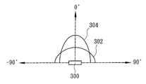
도 3A는 본 발명의 일실시예에 따른 혼색 LED의 발광 영역을 도시한 도면이고,3A is a view showing a light emitting region of a mixed color LED according to an embodiment of the present invention,
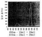
도 3B 내지 3D는 다양한 크기를 갖는 불그스름한 오렌지색광 칩 및 푸르스름한 녹색광 칩에 의해 생성된 다양한 발광 출력비에 관한 곡선을 도시한 도면이며,3B to 3D show curves for various light output ratios generated by reddish orange light chips and bluish green light chips having various sizes,
도 4는 본 발명의 다른 실시예에 따른 혼색 LED의 정면도이고,4 is a front view of a mixed color LED according to another embodiment of the present invention,
도 5는 본 발명의 또 다른 실시예에 따른 혼색 LED의 정면도이며,5 is a front view of a mixed color LED according to another embodiment of the present invention,
도 6은 본 발명의 또 다른 실시예에 따른 혼색 LED의 정면도이고,6 is a front view of a mixed color LED according to another embodiment of the present invention,
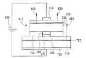
도 7은 본 발명의 또 다른 실시예에 따른 혼색 LED의 정면도이며,7 is a front view of a mixed color LED according to another embodiment of the present invention,
도 8A는 본 발명의 또 다른 실시예에 따른 혼색 LED의 정면도이고,8A is a front view of a mixed color LED according to another embodiment of the present invention,
도 8B는 도 8A에 도시된 본 발명의 실시예에 대응되는 회로를 도시한 도면이며,FIG. 8B is a diagram showing a circuit corresponding to the embodiment of the present invention shown in FIG. 8A,
도 9는 본 발명의 또 다른 실시예에 따른 혼색 LED의 정면도이고,9 is a front view of a mixed color LED according to another embodiment of the present invention,
도 10은 본 발명의 또 다른 실시예에 따른 혼색 LED의 정면도이며,10 is a front view of a mixed color LED according to another embodiment of the present invention,
도 11은 본 발명의 또 다른 실시예에 따른 혼색 LED의 정면도이고,11 is a front view of a mixed color LED according to another embodiment of the present invention,
도 12는 도 11의 아래부분에 위치한 두개의 불그스름한 오렌지색 LED의 평면도이며,FIG. 12 is a top view of two reddish orange LEDs located at the bottom of FIG. 11;
도 13은 도 11에 도시된 본 발명의 실시예에 대응되는 회로를 도시한 도면이고,FIG. 13 is a diagram illustrating a circuit corresponding to an embodiment of the present invention illustrated in FIG. 11.
도 14는 본 발명의 또 다른 실시예에 따른 혼색 LED의 정면도이며,14 is a front view of the multi-color LED according to another embodiment of the present invention,
도 15는 본 발명의 또 다른 실시예에 다른 혼색 LED의 정면도이다.15 is a front view of a mixed color LED according to another embodiment of the present invention.
본 발명은 발광 다이오드(LED)의 구조에 관한 것으로, 보다 상세하게는 상이한 컬러의 광을 방사하는 복수개의 LED가 칩 제조공정을 사용함으로써 전기적으로 직렬 및/또는 병렬로 연결되어 또 다른 컬러의 광을 생성하는 혼색 LED 구조에 관한 것이다.BACKGROUND OF THE
혼색 LED의 구조 및 동일한 제조방법에 관하여 당업자들은 여러개의 관련 자료들을 제출해 왔다. 예를 들면, 형광 가루를 활용할 수 있는 내용의 Nichia Chemical Industries, Ltd.의 미국특허 No. 5,998,925/6,069,440이 있으며, 여기서, 순수 청색광과 함께 혼합되어 백색광이 되는 황색광을 생성하기 위하여 이트륨 알루미늄 가닛(YAG; yttrium-aluminum-garnet) 형광체를 여기(勵起)하는데 청색광 LED를 사용할 수 있다. 이러한 방법에서, YAG 형광 물질은 460㎚ 파장의 InGaN 청색광 칩에 코팅되고, 이때, 청색광 LED는 청색에 대한 보색인 555㎚ 파장의 황색광을 생성하기 위하여 형광 물질을 조명하는데 사용되며, 렌즈의 원리는 청색광과 보색인 황색광을 혼합하여 백색광의 출력을 얻도록 적용되는 것이다. 비록 이러한 방법이 비용이 적게 든다는 장점이 있다 하더라도, 발광 효율이 좋지 않아서 (YAG 형광 물질의 낮은 광 변환성 때문) 높은 전력의 출력을 얻을 수가 없다. 더구나, 온도 및 동작 전류가 청색광 LED의 파장을 쉽게 변경시키기 때문에, YAG의 발광 효율은 악화되고(청색광 LED의 파장 변화에 대한 YAG 형광 물질의 광 변환 효율의 변화 때문), 즉, 높은 출력 세기를 갖는 백색광의 출력을 얻기가 매우 어려우며, 일정하게 동작하기도 어렵다.Many related materials have been submitted by those skilled in the art regarding the structure of the mixed color LED and the same manufacturing method. For example, U.S. Patent No. of Nichia Chemical Industries, Ltd., which can utilize fluorescent powder. 5,998,925 / 6,069,440, wherein blue light LEDs can be used to excite yttrium-aluminum-garnet (YAG) phosphors to produce yellow light that is mixed with pure blue light to become white light. In this method, the YAG fluorescent material is coated on an InGaN blue light chip with a wavelength of 460 nm, where the blue light LED is used to illuminate the fluorescent material to produce yellow light with a wavelength of 555 nm, which is complementary to blue. Is applied to mix the blue light with the complementary yellow light to obtain an output of white light. Although this method has the advantage of being low in cost, the luminous efficiency is not good (due to the low light conversion property of the YAG fluorescent material), and thus a high power output cannot be obtained. Moreover, since the temperature and operating current easily change the wavelength of the blue light LED, the luminous efficiency of the YAG is deteriorated (due to the change in the light conversion efficiency of the YAG fluorescent material with respect to the wavelength change of the blue light LED), i. It is very difficult to obtain the output of the white light having, and also difficult to operate constantly.
또한, ORSAM 광 반도체는 각각 세개의 기본 컬러(적색광, 녹색광, 청색광)를 방사하는 세개의 LED가 함께 백색광을 생성할 수 있도록 패키지되어 있다. 상기 방법에 있어서, 더 순수한 백색을 얻기 위하여 각각 세개의 LED의 밝기 및 파장을 조정할 필요가 있으나, 발광 컬러는 쉽게 조정될 수가 없다. 더구나, 상기 컬러들은 세개의 독립 광원이기 때문에 균일하지 않게 혼합될 것이다. 또한, 세개의 기본 컬러(적색광, 녹색광, 청색광)를 방사하는 각각의 LED의 반도체 재료들이 서로 상당히 상이하기 때문에, 구동 회로의 설계가 다소 복잡해져 제조 공정비가 더 많이 들게 된다.In addition, the ORSAM optical semiconductor is packaged so that three LEDs, each emitting three primary colors (red light, green light, and blue light), together produce white light. In this method, it is necessary to adjust the brightness and wavelength of each of the three LEDs to obtain a purer white color, but the emission color cannot be easily adjusted. Moreover, the colors will be mixed unevenly because they are three independent light sources. In addition, since the semiconductor materials of each LED emitting three basic colors (red light, green light, blue light) are significantly different from each other, the design of the driving circuit is somewhat complicated, resulting in higher manufacturing process costs.
본 발명에 있어서 주요한 발견은 LED의 발광 출력이 칩 크기와 전극의 형상 을 변경함으로써 변할 수 있다는 것이다. 따라서, 본 발명의 목적은 혼색 LED를 제공하는 것으로, 상이한 파장을 갖는 복수개의 LED는 칩 제조공정(플립 칩과 같은 칩 제조공정)을 사용함으로써 전기적으로 직렬 및/또는 병렬로 연결되며, 여기서 에피택시(epitaxy) 구조는 매우 넓은 발광 파장을 생성하도록 변경된다. 또한, 복수개의 LED의 칩 크기 및 전극 패드의 형상은 상이한 전류 확산과 상이한 발광 출력비를 생성하도록 변경되며, 그로인해 매우 넓은 발광 파장과 광범위하고 안정된 범위의 컬러 온도를 갖는 높은 전력의 발광 출력을 생성하게 된다.The main finding in the present invention is that the luminous output of the LED can be changed by changing the chip size and the shape of the electrode. It is therefore an object of the present invention to provide a mixed color LED, wherein a plurality of LEDs having different wavelengths are electrically connected in series and / or in parallel by using a chip manufacturing process (a chip manufacturing process such as a flip chip), where epi The epitaxy structure is modified to produce a very wide emission wavelength. In addition, the chip size and shape of the electrode pads of the plurality of LEDs are changed to produce different current spreading and different luminous output ratios, thereby generating a high power luminous output having a very wide luminous wavelength and a wide and stable range of color temperatures. Done.
본 발명의 다른 목적은 혼색 LED를 제공하는 것으로, 일정한 전류 또는 전압은 고정된 출력을 생성하는데 사용되며, 발광 파장은 온도 및 동작 전류 변화에 따라 쉽게 변하지 않을 것이다.Another object of the present invention is to provide a mixed color LED, wherein a constant current or voltage is used to produce a fixed output, and the emission wavelength will not easily change with temperature and operating current changes.
본 발명의 또 다른 목적은 혼색 LED를 제공하는 것으로, 각 모듈은 12V 또는 24V로 현재 적용중인 제품에 쉽게 사용될 수 있으며, 그로인해 그 동작 전압은 (3-4V의 청색광 및 2-2.5V의 황색광과 함께) 6V와 같다.Another object of the present invention is to provide a mixed color LED, wherein each module is 12V or 24V, which can be easily used in the current application, so that its operating voltage is (3-4V blue light and 2-2.5V yellow) With light) is equal to 6V.
또한, 본 발명의 다른 목적은 혼색 LED를 제공하는 것으로, 각 모듈의 동작 전압은 3∼4V의 범위를 가질 수 있다(이는 칩 제조공정을 이용하거나, 불그스름한 오렌지색광 LED 세트와 푸르스름한 녹색광 LED를 병렬로 연결함으로써 가능하다).In addition, another object of the present invention is to provide a mixed color LED, wherein the operating voltage of each module can be in the range of 3 to 4V (this can be achieved by using a chip manufacturing process or using a reddish orange LED set and a bluish green LED. By connecting in parallel).
또한, 본 발명의 또 다른 목적은 혼색 LED를 제공하는 것으로, 각 LED의 밝기는 각 LED의 상대 영역의 크기를 변화시킴으로써 조정될 수 있으며, 그로인해 컬러를 혼합한 후, 출력 파장을 쉽게 조정할 수 있다.In addition, another object of the present invention is to provide a mixed color LED, the brightness of each LED can be adjusted by changing the size of the relative area of each LED, so that after mixing the color, the output wavelength can be easily adjusted .
마지막으로, 본 발명의 또 다른 목적은 혼색 LED를 제공하는 것으로, 복수개 의 부착된 LED에 의해 방사되는 혼합된 광은 대칭적이다.Finally, another object of the present invention is to provide a mixed color LED, wherein the mixed light emitted by the plurality of attached LEDs is symmetrical.
본 발명의 전술된 목적에 따라, 본 발명은 혼색 LED를 제공하는 것으로, 제1 극성을 갖는 제1 전극; 제1 전극 상에 위치한 제1 LED 칩; 제1 LED 칩의 일부분에 위치한 제2 LED 칩; 제1 LED 칩의 다른 일부분 상에 위치한, 제2 극성을 갖는 제2 전극; 제2 LED 칩의 일부분에 위치한, 제1 극성을 갖는 제3 전극; 및 제2 LED 칩의 다른 일부분에 위치한, 제2 극성을 갖는 제4 전극을 포함한다. 또한, 전술된 제1 LED 칩은 황색광으로 변하거나 불그스름한 오렌지색광과 같이 방사될 수 있고, 전술된 제2 LED 칩은 청색광으로 변하거나 푸르스름한 녹색광과 같이 방사될 수 있다.In accordance with the above object of the present invention, the present invention provides a mixed color LED, comprising: a first electrode having a first polarity; A first LED chip located on the first electrode; A second LED chip located at a portion of the first LED chip; A second electrode having a second polarity, positioned on another portion of the first LED chip; A third electrode having a first polarity, positioned at a portion of the second LED chip; And a fourth electrode having a second polarity, located at another portion of the second LED chip. In addition, the above-described first LED chip may be turned into yellow light or emitted as reddish orange light, and the above-described second LED chip may be turned into blue light or emitted as bluish green light.
본 발명의 전술된 목적에 따라, 본 발명은 다른 혼색 LED를 제공하는 것으로, 제1 LED 칩; 제1 LED 칩의 제1 부분에 위치한 투명 접착층; 제1 LED 칩의 제2 부분에 위치한, 제1 극성을 갖는 제1 전극; 제1 LED 칩의 제3 부분에 위치한, 제2 극성을 갖는 제2 전극; 및 투명 접착층 위에 위치한 제2 LED 칩을 포함하며, 여기서, 제1 극성을 갖는 제3 전극은 제2 LED 칩의 저면의 일부에 위치하고, 제3 전극은 제2 전극과 접속해 있는 것을 특징으로 한다. 또한, 전술된 제1 LED 칩은 황색광 또는 불그스름한 오렌지색광과 같이 방사될 수 있고, 전술될 제2 LED 칩은 청색광 또는 푸르스름한 녹색광과 같이 방사될 수 있다.In accordance with the above object of the present invention, the present invention provides another mixed color LED, comprising: a first LED chip; A transparent adhesive layer located on the first portion of the first LED chip; A first electrode having a first polarity, positioned at a second portion of the first LED chip; A second electrode having a second polarity, positioned in the third portion of the first LED chip; And a second LED chip positioned on the transparent adhesive layer, wherein the third electrode having the first polarity is located at a portion of a bottom surface of the second LED chip, and the third electrode is connected to the second electrode. . In addition, the above-described first LED chip may be emitted as yellow light or reddish orange light, and the above-described second LED chip may be emitted as blue light or bluish green light.
본 발명의 전술된 목적에 따라, 본 발명은 또 다른 혼색 LED를 제공하는 것으로, 제1 LED 칩; 제1 LED 칩에 위치한 투명 접착층; 투명 접착층 상에 위치한 제2 LED 칩; 제2 LED 칩의 일부분에 위치한 제1 극성의 전극; 및 제2 LED 칩의 다른 부분에 위치한 제2 극성의 전극을 포함하는 것을 특징으로 한다. 또한, 제1 LED 칩은 포토루미네선스(photoluminescence) LED 칩이고 적어도 하나의 다중양자웰(multi quantum well)구조를 포함한다.In accordance with the above object of the present invention, the present invention provides another mixed color LED, comprising: a first LED chip; A transparent adhesive layer located on the first LED chip; A second LED chip located on the transparent adhesive layer; An electrode of a first polarity located at a portion of the second LED chip; And an electrode of a second polarity located at another portion of the second LED chip. In addition, the first LED chip is a photoluminescence LED chip and includes at least one multi quantum well structure.
본 발명의 전술된 목적에 따라, 본 발명은 또 다른 혼색 LED를 제공하는 것으로, 제1 극성을 갖는 제1 전극; 제1 전극 상에 위치한 제1 LED 칩; 제1 LED 칩의 일부분상에 위치한, 제2 극성을 갖는 제2 전극; 제2 전극에 접속하여 제2 전극 상에 위치한, 제1 극성을 갖는 제3 전극; 제1 LED 칩의 다른 부분에 위치하고 제3 전극과 동일한 높이를 갖는 투명 접착층; 투명 접착층과 제3 전극 상에 위치한 제2 LED 칩; 및 제2 LED 칩 상에 위치한, 제2 극성을 갖는 제4 전극을 포함한다. 또한, 전술된 제1 LED 칩은 황색광(584㎚) 또는 불그스름한 오렌지색광(610㎚)과 같이 방사될 수 있으며, 전술된 제2 LED 칩은 청색광(480㎚) 또는 푸르스름한 녹색광(495㎚)과 같이 방사될 수 있다.According to the above object of the present invention, the present invention provides another mixed color LED, comprising: a first electrode having a first polarity; A first LED chip located on the first electrode; A second electrode having a second polarity located on a portion of the first LED chip; A third electrode having a first polarity connected to the second electrode and positioned on the second electrode; A transparent adhesive layer positioned on another portion of the first LED chip and having the same height as the third electrode; A second LED chip positioned on the transparent adhesive layer and the third electrode; And a fourth electrode having a second polarity, positioned on the second LED chip. In addition, the above-described first LED chip may be emitted as yellow light (584 nm) or reddish orange light (610 nm), and the above-mentioned second LED chip may be blue light (480 nm) or bluish green light (495 nm). It can be radiated as follows.
본 발명의 전술된 목적에 따라, 본 발명은 또 다른 혼색 LED를 제공하는 것으로, 제1 극성을 갖는 제1 전극; 제1 전극 상에 위치한 제1 LED 칩; 제1 LED 칩의 일부분에 위치한, 제2 극성을 갖는 제2 전극; 제2 극성을 갖는 제2 전극 상에 위치한, 제2 극성을 갖는 제3 전극; 제1 LED 칩의 다른 일부분에 위치한 절연층; 절연층 상에 위치한, 제1 극성을 갖는 제4 전극; 제2 극성을 갖는 제3 전극과 제1 극성을 갖는 제4 전극 상에 위치한 제2 LED 칩; 및 제2 LED 칩 상에 위치한 기판을 포함한다. 또한, 전술된 제1 LED 칩은 황색광 또는 불그스름한 오렌지색광으로 변하 는 것 같이 방사될 수 있고, 전술된 제2 LED 칩은 청색광 또는 푸르스름한 녹색광으로 변하는 것 같이 방사될 수 있다.According to the above object of the present invention, the present invention provides another mixed color LED, comprising: a first electrode having a first polarity; A first LED chip located on the first electrode; A second electrode having a second polarity, positioned at a portion of the first LED chip; A third electrode having a second polarity, positioned on the second electrode having the second polarity; An insulating layer located on another portion of the first LED chip; A fourth electrode having a first polarity, positioned on the insulating layer; A second LED chip positioned on the third electrode having the second polarity and the fourth electrode having the first polarity; And a substrate located on the second LED chip. In addition, the above-described first LED chip may be emitted as changing to yellow light or reddish orange light, and the above-mentioned second LED chip may be emitted as changing to blue light or bluish green light.
본 발명의 전술된 목적에 따라, 본 발명은 또 다른 혼색 LED를 제공하는 것으로. 제1 극성을 갖는 제1 전극; 제1 전극 상에 위치한 제1 LED 칩; 제1 LED 칩 상에 위치한, 제2 극성을 갖는 제2 전극; 제2 극성을 갖는 제2 전극 상에 위치한, 제2 극성을 갖는 제3 전극; 제2 극성을 갖는 제3 전극 상에 위치한 전기전도성을 띤 기판; 전기전도성을 띤 기판에 위치한 제2 LED 칩; 및 제2 LED 칩에 위치한, 제1 극성을 갖는 제4 전극을 포함한다. 또한, 전술된 제1 LED 칩은 황색광 또는 불그스름한 오렌지색광으로 변하는 것 같이 방사될 수 있고, 전술된 제2 LED 칩은 청색광 또는 푸르스름한 녹색광으로 변하는 것 같이 방사될 수 있다.In accordance with the above object of the present invention, the present invention provides another mixed color LED. A first electrode having a first polarity; A first LED chip located on the first electrode; A second electrode having a second polarity, positioned on the first LED chip; A third electrode having a second polarity, positioned on the second electrode having the second polarity; An electrically conductive substrate positioned on a third electrode having a second polarity; A second LED chip located on the electrically conductive substrate; And a fourth electrode having a first polarity, positioned on the second LED chip. In addition, the above-described first LED chip may be emitted as changing to yellow light or reddish orange light, and the above-mentioned second LED chip may be emitted as changing to blue light or bluish green light.
본 발명의 전술된 목적에 따라, 본 발명은 또 다른 혼색 LED를 제공하는 것으로, 제1 LED 칩; 제1 LED 칩에 전기적으로 직렬 연결된 제2 LED 칩; 및 제2 LED 칩에 전기적으로 직렬 연결된 제3 LED 칩을 포함하며, 여기서, 제1 LED 칩, 제2 LED 칩 및 제3 LED 칩은 적색, 녹색 또는 청색광을 방사할 수 있다.In accordance with the above object of the present invention, the present invention provides another mixed color LED, comprising: a first LED chip; A second LED chip electrically connected in series with the first LED chip; And a third LED chip electrically connected to the second LED chip, wherein the first LED chip, the second LED chip, and the third LED chip may emit red, green, or blue light.
본 발명의 전술된 목적에 따라, 본 발명은 여전히 또 다른 혼색 LED를 제공하는 것으로, 제1 극성을 갖는 제1 전극 및 제2 극성을 갖는 제2 전극을 갖는 제1 LED 칩; 제1 극성을 갖는 제3 전극 및 제2 극성을 갖는 제4 전극을 갖는 제2 LED 칩으로, 여기서 제3 전극은 제2 전극에 전기적으로 연결되어 있고; 제1 극성을 갖는 제5 전극 및 제2 극성을 갖는 제6 전극을 갖는 제3 LED 칩을 포함하며, 여기서 제5 전극은 제1 전극에 전기적으로 연결되어 있고, 제6 전극은 제4 전극에 전기적 으로 연결되어 있다. 또한, 전술된 제1 LED 칩과 제2 LED 칩은 불그스름한 오렌지색광 또는 황색광을 방사할 수 있고, 제3 LED 칩은 푸르스름한 녹색광 또는 청색광으로 변하는 것 같이 방사할 수 있다. According to the above object of the present invention, the present invention still provides another mixed color LED, comprising: a first LED chip having a first electrode having a first polarity and a second electrode having a second polarity; A second LED chip having a third electrode having a first polarity and a fourth electrode having a second polarity, wherein the third electrode is electrically connected to the second electrode; And a third LED chip having a fifth electrode having a first polarity and a sixth electrode having a second polarity, wherein the fifth electrode is electrically connected to the first electrode, and the sixth electrode is connected to the fourth electrode. It is electrically connected. In addition, the first LED chip and the second LED chip described above may emit reddish orange light or yellow light, and the third LED chip may emit light as it turns into bluish green light or blue light.
본 발명은 혼색 LED의 구조에 관한 것으로, 상이한 컬러의 광을 방사하는 복수개의 LED는 또 다른 컬러의 광을 생성하도록 칩 제조공정을 사용함으로써 전기적으로 직렬 및/또는 병렬로 연결될 수 있다. 도 1A 및 도 1B는 각각 본 발명의 일실시예에 따른 혼색 LED의 황색광 LED와 청색광 LED의 평면도를 도시하고 있다. 도 1A에서, 황색광 LED(110)는 그 위에 양의 전극(120)을 포함하며, 도 1B에서, 청색광 LED(130)는 그 위에 음의 전극(140)과 양의 전극(150)을 포함한다. 도 2A는 본 발명의 일실시예에 따른 혼색 LED의 평면도를 도시하고 있다. 도 2A에 도시된 혼색 LED는 도 1B에 도시된 청색광 LED(130)를 투명 접착제(미도시)로 도 1A에 도시된 황색광 LED(110)에 부착함으로써 제조된다. 또한, 황색광 LED(110)상의 양의 전극(120)과 청색광 LED(130)상의 음의 전극(140)은 연결선(160)을 통해 직렬로 단일 회로를 형성하도록 전기적으로 연결된다. 또한, 사용된 투명 접착제는 고투명성, 고온 저항 및 월등한 열 전도성을 가짐으로써 고전력 동작 조건에서 사용될 수 있다. 또한, 청색광 LED(130)의 재료는 BAlGaInPAs 시리즈 등에 속할 수 있고, 황색광 LED(110)의 재료는 AlGaInPAs 시리즈 등에 속할 수 있다. 게다가, 황색광 LED(110)의 음의 전극(도 1A와 도 2A에는 도시되지 않았으나, 도 2B에는 도시되어 있음)은 칩의 저면에 있다. 부착된 혼색 LED에 의해 방사된 혼합광은 대칭을 이루며 단일 전원으로 동작할 수 있는 장점을 갖는다.The present invention relates to the structure of a mixed color LED, wherein a plurality of LEDs emitting light of different colors can be electrically connected in series and / or in parallel by using a chip manufacturing process to produce light of another color. 1A and 1B show a top view of a yellow light LED and a blue light LED of a mixed LED according to one embodiment of the present invention, respectively. In FIG. 1A, the
도 2B는 본 발명의 일실시예에 따른 혼색 LED의 정면도를 도시하고 있다. 도 2B에 도시된 혼색 LED의 최저층은 황색광 LED(110)(발광층(112) 포함)의 음의 전극인 음의 전극(125)이며, 황색광 LED(110)는 음의 전극(125)상에 위치한다. 청색광 LED(130)(발광층(132) 포함)는 황색광 LED(110)의 일부분 상에 위치하며, 황색광 LED(110)의 양의 전극(120)은 황색광 LED(110)의 다른 일부분에 위치한다. 또한, 청색광 LED(130)의 음의 전극(140)은 청색광 LED(130)의 일부분상에 위치하며, 청색광 LED(130)의 양의 전극(150)은 청색광 LED(130)의 다른 부분상에 위치한다. 또한, 전술된 바와 같이, 황색광 LED(110)상의 양의 전극(120)과 청색광 LED(130)상의 음의 전극(140)은 연결선(160)을 통해 직렬로 단일 회로를 형성하도록 전기적으로 연결되어 있다. 따라서, 황색광 LED(110)에 의해 방사된 광은 두 부분으로 나눌 수 있으며, 하나는 순수 황색광(210)이고, 다른 하나는 청색광 LED를 통과하는 황색광(212)이며, 이는 청색광 LED(130)의 에너지 갭이 황색광 LED(110)보다 더 넓기 때문이다. 따라서, 청색광 LED를 통과하는 황색광(212)은 청색광 LED(130)에 의해 방사된 청색광(220)과 혼합되어 백색광(230)이 될 수 있다. 또한, 본 발명의 전술된 실시예에 따른 혼색 LED의 발광 영역은 도 3A에 도시되어 있으며, 황색광 영역(302)과 청색광 영역(304)은 부착된 황색광 LED(110)와 청색광 LED(130)에 의해 방사된 광인 혼합광이 각각 대칭을 이룬다는 것을 도시한다.2B shows a front view of a mixed color LED in accordance with one embodiment of the present invention. The lowest layer of the mixed color LED shown in FIG. 2B is a
도 2A 및 2B에 도시된 바와 같이 전술된 실시예에서, 480㎚ 파장의 청색광 LED(130)와 584㎚ 파장의 황색광 LED(110)가 사용될 수 있다. 에칭 및 금속 증발 공정 후, 청색광 LED(130)는 40mil×40mil 크기 또는 10mil×10mil로 변하는 크기를 갖도록 절단되며, 황색광 LED(110)는 40mil×80mil 크기 또는 16mil×16mil로 변하는 크기를 갖도록 절단된 후, 고열전도성을 지닌 투명 접착제를 이용하여 청색광 LED(130)를 황색광 LED(110)에 부착한다. 즉, 도 2A에서, 폭(180)은 40mil이고, 폭(170)은 80mil이며, 두개의 폭(190, 200)은 각각 20mil이다. 접착공정이 이루어질 때, 와이어본딩용 장치는 연결선(160)을 통하여 직렬로 회로 모듈을 형성하도록 청색광 LED(130)의 음의 전극(140)을 황색광 LED(110)의 양의 전극(120)에 전기적으로 연결시킨다. 전원은 청색광 LED(130)의 양의 전극(150)과 황색광 LED(110)의 음의 전극(125)에 공급되어 적절하게 회로에서 사용될 수 있는 6V 또는 12V의 모듈을 형성한다. 또한, 청색광 LED(130)의 폭(180)(495㎚ 파장의 푸르스름한 녹색광으로 변할 수도 있음)이 변경될 수 있거나, 황색광 LED(110)의 폭(190) 또는 폭(200)(610㎚의 불그스름한 오렌지색광으로 변할 수도 있음)이 변경될 수 있어서, 출력 세기를 조정할 수 있다. 그런 다음, 필요에 따라서, 상대적인 칩 크기는 다른 발광 출력비 및 파장 출력을 생성하도록 조정될 수 있다. 일반적으로, 상부 및 하부 칩의 길이와 폭은 7mil∼200mil이 될 수 있다. 상부 및 하부 칩의 크기는 두 칩의 출력 전원, 변화시킨 파장, 및 출력의 컬러 온도에 의존하게 된다. 도 3B 내지 3D는 다양한 크기를 갖는 불그스름한 오렌지색광 칩과 푸르스름한 녹색광 칩에 의해 생성된 다양한 발광 출력비에 관한 것으로, 그로인해 다양한 컬러 온도를 갖는 혼색광을 생성한다.In the above-described embodiment as shown in FIGS. 2A and 2B, a blue
도 2A 및 2B에 도시된 바와 같이 전술된 실시예에서, 480㎚ 파장의 청색광 LED(130)와 584㎚의 황색광 LED(110)도 사용될 수 있다. 청색광 LED(130)의 공정이 완료될 때, 그것은 황색광 LED(110)상에 부착되어 절단과 같은 순차적인 공정에 의해 진행될 수 있다. 도 2B에 도시된 전극은 본 발명의 청구범위를 벗어나지 않는 범위내에서 반대 극성을 갖는 것들로 동시에 대체될 수 있다.In the above-described embodiment as shown in FIGS. 2A and 2B, a blue
도 4는 본 발명의 다른 실시예에 따른 혼색 LED의 정면도를 도시하고 있다. 도 4에 도시된 최저층은 BAlGaInPAs 불그스름한 오렌지색광 LED(310)(발광층(312) 포함)이다. 투명 접착층(390)(SiO2 등)은 BAlGaInPAs 불그스름한 오렌지색광 LED(310)의 제1부분에 위치하고, BAlGaInPAs 불그스름한 오렌지색광 LED(310)의 양의 전극(320)은 BAlGaInPAs 불그스름한 오렌지색광 LED(310)의 제1 부분의 제2 부분에 위치하며, 또한, BAlGaInPAs 불그스름한 오렌지색광 LED(310)의 음의 전극(325)은 BAlGaInPAs 불그스름한 오렌지색광 LED(310)의 제3 부분에 위치한다. 또한, BAlGaInNPAs 푸르스름한 녹색광 LED(330)(발광층(332) 포함)는 투명 접착층(390)상에 위치하며, BAlGaInNPAs 푸르스름한 녹색광 LED(330)의 저층의 일부분은 그 위에 양의 전극(350)을 포함하고, 상기 양의 전극(350)은 BAlGaInPAs 불그스름한 오렌지색광 LED(310)의 음의 전극(325)과 접속해 있다. 또한, BAlGaInNPAs 푸르스름한 녹색광 LED(330)의 음의 전극(340)은 투명 접착층(390)상에 위치한다. 따라서, BAlGaInPAs 불그스름한 오렌지색광 LED(310)에 의해 방사된 광은 두개의 부분으로 나눌 수 있다. 즉, 한 부분은 순수 불그스름한 오렌지색광(미도시)이고, 다른 부분은 푸르스름한 녹색광 LED를 통과하는 불그스름한 오렌지색광(412)이다. 따라서, 푸르스름한 녹색광 LED를 통과하는 불그스름한 오렌지색광(412)은 BAlGaInNPAs 푸르스름한 녹색광 LED(330)에 의해 방사되는 푸르스름한 녹색광(420)과 혼합되어 백색광(430)이 된다. 또한, 전술된 BAlGaInPAs 불그스름한 오렌지색광 LED(310)는 황색광을 방사할 수 있는 다른 유형의 LED 칩으로 대체될 수 있고, 전술된 BAlGaInNPAs 푸르스름한 녹색광 LED(330)는 청색광을 방사할 수 있는 다른 유형의 LED 칩으로 대체될 수 있으며, 그로인해, 본 발명의 혼색 LED는 백색광을 방사할 수 있다.4 illustrates a front view of a mixed color LED according to another embodiment of the present invention. The lowest layer shown in FIG. 4 is BAlGaInPAs reddish orange light LED 310 (including light emitting layer 312). A transparent adhesive layer 390 (such as SiO2 ) is located in the first portion of the BAlGaInPAs reddish orange
도 4에 도시된 바와 같이 전술된 실시예에서, 약 495㎚ 파장의 BAlGaInNPAs 푸르스름한 녹색광 LED(330)와 약 610㎚ 파장의 BAlGaInPAs 불그스름한 오렌지색광 LED(310)가 사용될 수 있다. 에칭 및 금속 증발 공정 후, BAlGaInNPAs 푸르스름한 녹색광 LED(330)는 40mil×40mil 크기를 갖도록 절단되며, BAlGaInPAs 불그스름한 오렌지색광 LED(310)는 40mil×80mil 크기를 갖도록 절단된다. 그런 다음, 고열전도성을 지닌 전기전도 금속 물질(미도시)을 사용하여 BAlGaInPAs 불그스름한 오렌지색광 LED(310)의 음의 전극(325)과 BAlGaInNPAs 푸르스름한 녹색광 LED(330)의 양의 전극(350)을 부착시킨다. 전원(400)은 회로에서 적절하게 사용될 수 있도록 6V 및 12V의 모듈에서 BAlGaInNPAs 푸르스름한 녹색광 LED(330)의 음의 전극(340)과 BAlGaInPAs 불그스름한 오렌지색광 LED(310)의 양의 전극(320)으로 공급된다. 또한, BAlGaInNPAs 푸르스름한 녹색광 LED(330)(청색광으로 변경 가능)의 폭이 변경될 수 있거나, 또는 BAlGaInPAs 불그스름한 오렌지색광 LED(310)(황색광으로 변경 가능)의 폭이 변경될 수 있으며, 그로인해 출력 세기를 조정할 수 있다. 그런 다음, 필요에 따라, 상대적인 칩 크기는 파장의 출력을 변경하기 위해 조정될 수 있고, 백색광이 생성될 수 있으며, 다양한 컬러 온도를 조절할 수 있다.In the above-described embodiment as shown in FIG. 4, BAlGaInNPAs bluish
도 5는 본 발명의 또 다른 실시예에 따른 혼색 LED의 정면도를 도시하고 있다. 도 5에 도시된 최저층은 다중양자웰 구조(512)를 더 포함하는 황색광 포토루미네선스 구조(510)로 적색광을 갖는 LED이다. 따라서, 황색광 포토루미네선스 구조(510)로 적색광을 갖는 LED는 외부 전원(630)에 연결되어 사용되는 양의 전극 또는 음의 전극이 요구되지 않는다. 즉, 외부 전원(630)의 두 전극은 AlGaInBNAsP 청색광 LED(530)(발광층(532) 포함)의 양의 전극(550)과 음의 전극(540)에 각각 전기적으로 연결된다. 따라서, AlGaInBNAsP 청색광 LED(530)에 의해 방사되는 청색광(620)은 황색광 포토루미네선스 구조(510)로 적색광을 갖는 LED를 여기시키는데 사용될 수 있으며, 그로인해 황색광 포토루미네선스 구조(510)로 적색광을 갖는 LED는 황색광(610)으로 적색광을 방사시키며, 청색광(620)과 혼합될 황색광(610)에 대한 적색광으로 백색광에 대한 자색광을 만든다. 또한, 투명 접착층(590)(투명 열전도성 접착제 등)은 AlGaInBNAsP 청색광 LED(530)와 황색광 포토루미네선스 구조(510)에 대한 적색광을 갖는 LED를 부착하는데 사용된다. 또한, 도 5에 도시된 전극은 본 발명의 청구범위를 벗어나지 않는 범위내에서 반대 극성을 갖는 것들로 동시에 대체할 수 있다.Figure 5 shows a front view of a mixed color LED according to another embodiment of the present invention. The lowest layer shown in FIG. 5 is a yellow
도 6은 본 발명의 또 다른 실시예에 따른 혼색 LED의 정면도를 도시하고 있다. 도 6에 도시된 바와 같이, 음의 전극(725)은 AlGaInAsP 황색광 LED(710)(발광층(712) 포함)의 저면에 위치하고, AlGaInAsP 황색광 LED(710)의 양의 전극(720)은 AlGaInAsP 황색광 LED(710) 표면의 일부분에 위치한다. 또한, AlGaInBNAsP 청색광 LED(730)(발광층(732) 포함)의 음의 전극(740)은 양의 전극(720)상에 위치되어 양의 전극(720)과 접속해 있다. 또한, 투명 접착층(790)(SiO2 또는 열전도성 접착제 등)은 AlGaInAsP 황색광 LED(710)의 다른 일부분 상에 위치하며, 투명 접착층(790)의 상부는 음의 전극(740)의 상부와 동일한 높이를 갖는다. 또한, 전원(830)의 두 전극은 AlGaInBNAsP 청색광 LED(730)의 양의 전극(750)과 AlGaInAsP 황색광 LED(710)의 음의 전극(725)에 전기적으로 연결된다. 따라서, AlGaInBNAsP 청색광 LED(730)에 의해 방사된 청색광(820)은 AlGaInAsP 황색광 LED(710)에 의해 방사된 황색광(810)과 혼합되어 백색광이 될 수 있다. 또한, 전술된 AlGaInAsP 황색광 LED(710)는 불그스름한 오렌지색광을 방사할 수 있는 다른 유형의 LED 칩으로 대체될 수 있고, AlGaInBNAsP 청색광 LED(730)는 푸르스름한 녹색광을 방사할 수 있는 다른 유형의 LED 칩으로 대체될 수 있으며, 그로인해 본 발명의 혼색 LED는 백색광을 방사할 수 있다. 게다가, 도 6에 도시된 전극은 본 발명의 청구범위를 벗어나지 않는 범위내에서 반대 극성을 갖는 것들로 동시에 대체될 수 있다.Figure 6 shows a front view of a mixed color LED according to another embodiment of the present invention. As shown in FIG. 6, the
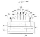
도 7은 본 발명의 또 다른 실시예에 따른 혼색 LED의 정면도를 도시하고 있다. 도 7에 도시된 최저층은 황녹색 포토루미네선스 다중양자웰(912)구조와 적색 포토루미네선스 다중양자웰(914)구조를 포함하는 포토루미네선스 구조(910)를 갖는 LED이다. 따라서, 포토루미네선스 구조(910)를 갖는 LED는 외부 전원(미도시)에 연결하기 위해 사용되는 양의 전극 또는 음의 전극이 요구되지 않는다. 즉, 외부 전원의 두 전극은 푸르스름한 녹색광 LED(920)의 양의 전극(930)과 음의 전극(940)에 각각 전기적으로 연결된다. 따라서, 푸르스름한 녹색광 LED(920)에 의해 방사된 청색광(970)은 포토루미네선스 구조(910)의 LED를 갖는 LED를 여기시키는데 사용되며, 그로인해 포토루미네선스 구조(910)를 갖는 LED는 적색광(950)과 황녹색광(960)을 방사할 수 있고, 적색광(950)과 황녹색광(960)은 청색광(970)과 혼합되어 백색광(980)이 된다.7 illustrates a front view of a mixed color LED according to another embodiment of the present invention. The lowest layer shown in FIG. 7 is an LED having a
도 8A는 본 발명의 또 다른 실시예에 따른 혼색 LED의 정면도를 도시하고 있다. 도 8A에 도시된 바와 같이, 음의 전극(1112)은 황색광 LED(1110)(발광층(1111) 포함)의 저면에 위치하고, 황색광 LED(1110)의 양의 전극(1114)은 황색광 LED(1110) 표면의 일부분 상에 위치한다. 절연층(1130)(산화층 등)은 황색광 LED(1110) 표면의 나머지 부분상에 위치한다. 청색광 LED(1120)(발광층(1121) 포함)에 관하여, 이것은 기판(1100)(사파이어와 같은 물질로 제조된 절연성 기판)과 양의 전극(1124)과 음의 전극(1122)를 가지며, 여기서, 상기 기판(1100)은 청색광 LED(1120) 상에 위치하고, 양의 전극(1124)과 음의 전극(1122)은 청색광 LED(1120)의 저면에 위치한다. 더구나, 청색광 LED(1120)의 음의 전극(1122)은 절연층(1130)상에 위치하며, 청색광 LED(1120)의 양의 전극(1124)은 황색광 LED(1110)의 양의 전극(1114)과 전기적으로 연결된다. 더나아가, 연결선(1140)은 황색광 LED(1110)와 청색광 LED(1120) 사이를 전기적으로 병렬 연결하기 위하여, 황색광 LED(1110)의 음의 전극(1112)과 청색광 LED(1120)의 음의 전극(1122)을 연결하는데 사용될 수 있다. 또한, 전원(1150)의 두 전극은 황 색광 LED(1110)의 양의 전극(1114)(또는 청색광 LED(1120)의 양의 전극(1124))과 청색광 LED(1120)의 음의 전극(1122)(또는 황색광 LED(1110)의 음의 전극(1112))에 전기적으로 연결될 수 있다. 따라서, 청색광 LED(1120)에 의해 방사된 청색광은 황색광 LED(1110)에 의해 방사된 황색광과 혼합되어 백색광이 될 수 있다. 또한, 전술된 황색광 LED(1110)는 불그스름한 오렌지색광을 방사할 수 있는 다른 유형의 LED 칩으로 대체될 수 있고, 청색광 LED(1120)는 푸르스름한 녹색광을 방사할 수 있는 다른 유형의 LED 칩으로 대체될 수 있으며, 그로인해 본 발명의 혼색 LED는 백색광을 방사할 수 있다. 게다가, 도 8A에 도시된 전극은 본 발명의 청구범위를 벗어나지 않는 범위내에서 반대 극성을 갖는 것들로 동시에 대체될 수 있다. 또한, 도 8B는 도 8A에 도시된 본 발명의 실시예에 대응되는 회로를 도시하고 있다.8A shows a front view of a mixed color LED according to another embodiment of the present invention. As shown in FIG. 8A, the
도 9는 본 발명의 또 다른 실시예에 따른 혼색 LED의 정면도를 도시하고 있다. 도 9에 도시된 바와 같이, 음의 전극(1212)은 황색광 LED(1210)(BAlGaInPAs등으로 제조됨)의 저면에 위치하고, 황색광 LED(1210)의 양의 전극(1214)은 황색광 LED(1210)의 표면상에 위치한다. 청색광 LED(1220)(BAlGaInPAs등으로 제조됨)에 관하여, 그것은 양의 전극(1224), 음의 전극(1222)을 가지며, 여기서, 청색광 LED(1220)는 전기전도성 기판(1200)상에 위치하고, 음의 전극(1222)은 청색광 LED(1220) 상에 위치하며, 양의 전극(1224)은 전기전도성 기판(1200)의 저면에 위치한다. 더구나, 청색광 LED(1220)의 양의 전극(1224)은 황색광 LED(1210)의 양의 전극(1214)에 전기적으로 연결된다. 더나아가, 연결선(1240)은 황색광 LED(1210)와 청색광 LED(1220) 사이를 전기적으로 병렬 연결하기 위하여, 황색광 LED(1210)의 음의 전극(1212)과 청색광 LED(1220)의 음의 전극(1222)을 연결하는데 사용될 수 있다. 또한, 전원(1250)의 두 전극은 황색광 LED(1210)의 양의 전극(1214)(또는 청색광 LED(1220)의 양의 전극(1224))과 청색광 LED(1220)의 음의 전극(1222)(또는 황색광 LED(1210)의 음의 전극(1212))에 각각 전기적으로 연결될 수 있다. 따라서, 청색광 LED(1220)에 의해 방사된 청색광은 황색광 LED(1210)에 의해 방사된 황색광과 혼합되어 백색광이 될 수 있다. 또한, 전술된 황색광 LED(1210)는 불그스름한 오렌지색광을 방사할 수 있는 다른 유형의 LED 칩으로 대체될 수 있고, 청색광 LED(1220)는 푸르스름한 녹색광을 방사할 수 있는 다른 유형의 LED 칩으로 대체될 수 있으며, 그로인해 본 발명의 혼색 LED는 백색광을 방사할 수 있다. 또한, 도 9에 도시된 전극은 본 발명의 청구범위를 벗어나지 않는 범위내에서 반대 극성을 갖는 것들로 동시에 대체될 수 있다.9 illustrates a front view of a mixed color LED according to another embodiment of the present invention. As shown in FIG. 9, the
도 8A 및 도 9에 도시된 전술된 실시예에서, 불그스름한 오렌지색(또는 황색)광 LED의 에피택셜(epitaxial) 구조는 동작 전압을 올리기 위하여 내부 임피던스를 증가시키도록 조정될 수 있으며, 여기서, 동작 전류가 5mA∼50mA일 때, 동작 전압은 2.3V∼3.2V로 상승될 수 있으며, 그로인해 불그스름한 오렌지색(또는 황색)광 LED의 에피택셜 구조는 푸르스름한 녹색(또는 청색)광 LED와 병렬로 연결된 플립-칩이 되어 백색광 또는 다른 컬러의 광을 생성할 수 있다.In the above-described embodiment shown in FIGS. 8A and 9, the epitaxial structure of the reddish orange (or amber) light LED can be adjusted to increase the internal impedance to raise the operating voltage, where the operating current When 5mA to 50mA, the operating voltage can rise to 2.3V to 3.2V, so that the epitaxial structure of the reddish orange (or amber) light LED is flipped in parallel with the bluish green (or blue) light LED Can be a chip to produce white light or other colored light
도 10은 본 발명의 또 다른 실시예에 따른 혼색 LED의 정면도를 도시하고 있다. 도 10에 도시된 바와 같이, 혼색 LED는 적색광 LED 칩(1310), 녹색광 LED 칩(1320) 및 청색광 LED 칩(1330)을 포함한다. 상기 적색광 LED 칩(1310)은 그 하 부에 음의 전극(1312) 및 그 상부에 양의 전극(1314)를 갖고, 상기 녹색광 LED 칩(1320)은 그 하부에 음의 전극(1322) 및 그 상부에 양의 전극(1324)를 가지며, 상기 청색광 LED 칩(1330)은 그 하부에 음의 전극(1332) 및 그 상부에 양의 전극(1334)을 갖는다. 상기 양의 전극(1314)과 음의 전극(1322)은 전기적으로 연결되며, 상기 양의 전극(1324)과 음의 전극(1332)은 적색광 LED 칩(1310), 녹색광 LED 칩(1320) 및 청색광 LED 칩(1330)이 전기적으로 직렬 연결될 수 있도록 전기적으로 연결된다. 또한, 전원(1370)의 두 전극은 청색광 LED(1330)의 양의 전극(1334)과 적색광 LED(1310)의 음의 전극(1312)에 각각 전기적으로 연결될 수 있다. 따라서, 청색광 LED(1330)에 의해 방사된 청색광(1360), 녹색광 LED(1320)에 의해 방사된 녹색광(1350), 및 적색광 LED(1310)에 의해 방사된 적색광(1340)은 혼합되어 백색광이 될 수 있다. 또한, 적색광 LED 칩(1310), 녹색광 LED 칩(1320) 및 청색광 LED 칩(1330) 사이의 상대 위치 관계는 도 10에 도시된 것처럼 제한될 필요는 없으며, 본 발명의 청구범위를 벗어나지 않는 범위내에서 임의적으로 변경 가능하다. 예를 들면, 청색광 LED 칩이 최저층, 적색광 LED 칩이 중간 층, 및 녹색광 LED 칩이 최상층에 놓일 수 있다. 게다가, 도 10에 도시된 전극은 본 발명의 청구범위를 벗어나지 않는 범위내에서 반대 극성을 갖는 것들로 동시에 대체될 수 있다.10 illustrates a front view of a mixed color LED according to another embodiment of the present invention. As shown in FIG. 10, the mixed color LED includes a red
도 11은 본 발명의 또 다른 실시예에 따른 혼색 LED의 정면도를 도시하고 있다. 도 11에 도시된 혼색 LED(BAlGaInPAs와 같은 물질로 제조됨)는 두개의 BAlGaInPAs 불그스름한 오렌지색 LED 칩과 하나의 BAlGaInNPAs 푸르스름한 녹색 LED 칩으로 구성된다. 제1의 불그스름한 오렌지색 LED 칩은 절연성의 반절연 기판(1400)(반절연성 GaAs 등)상에 위치한 N-타입 도전층(1410), N-타입 차단층(1411), 불그스름한 오렌지색 LED 발광층(1412), 및 P-타입 차단층(1413)과, N-타입 전극(1415)과 P-타입 전극(1417)을 포함하며, 여기서, N-타입 전극(1415)과 P-타입 전극(1417)은 N-타입 전도층(1410)의 일부 및 P-타입 차단층(1413)의 일부분에 각각 위치한다. 제2의 불그스름한 오렌지색 LED 칩은 반절연 기판(1400)상에 위치한 N-타입 전도층(1420), N-타입 차단층(1421), 불그스름한 오렌지색 LED 발광층(1422), 및 P-타입 차단층(1423)과, N-타입 전극(1425)과 P-타입 전극(1427)으로 구성된 스택 구조를 포함하며, 여기서, N-타입 전극(1425)과 P-타입 전극(1427)은 N-타입 전도층(1420)의 일부 및 P-타입 차단층(1423)의 일부분에 각각 위치한다. 상기 푸르스름한 녹색 LED 칩은 투명 기판(1430)(사파이어와 같은 재료로 제조됨), N-타입 전도층(1436), N-타입 차단층(1431), 푸르스름한 녹색 LED 발광층(1432), P-타입 차단층(1433), N-타입 전극(1435) 및 P-타입 전극(1437)으로 구성된 스택 구조를 포함하며, 여기서, N-타입 전극(1435, 1437)은 N-타입 전도층(1436)의 일부 및 P-타입 차단층(1433)의 일부분에 각각 위치한다. 전술된 푸르스름한 녹색 LED 칩은 플립-칩 기법에 의해 제1의 불그스름한 오렌지색 LED 칩과 제2의 불그스름한 오렌지색 LED 칩에 부착될 수 있다. 또한, 도 11에 도시된 바와 같이, 조합된 혼색 LED는 절연층(1440), 금속층(1450), 절연층(1460), 금속 전극(1480), 금속 전극(1485), 및 투명 절연 접착제(1470) 등을 더 포함한다. 상기 절연층(1440), 절연층(1460), 및 투명 절연 접착제(1470)는 세 개의 LED 칩 사이에 절연성을 보장하도록 사용될 수 있다. 상기 금속층(1450)은 N-타입 전극(1415)과 P-타입 전극(1427)을 전기적으로 연결하는데 사용될 수 있으며, 그로인해 두개의 불그스름한 오렌지색 LED 칩은 전기적으로 직렬 연결될 수 있다. 상기 금속 전극(1480)은 P-타입 전극(1417)과 P-타입 전극(1437)을 전기적으로 연결하고, 상기 금속 전극(1485)은 N-타입 전극(1425)과 N-타입 전극(1435)을 전기적으로 연결하며, 그로인해 두개의 불그스름한 오렌지색 LED 칩이 직렬로 연결된 후에, 두개의 불그스름한 오렌지색 LED 칩은 푸르스름한 녹색 LED 칩에 더 연결될 수 있다. 또한, 전원(1490)(3V∼4V)의 두 전극은 금속 전극(1480)과 금속 전극(1485)에 각각 연결될 수 있다. 따라서, 푸르스름한 녹색광 LED 발광층(1432)에 의해 방사된 푸르스름한 녹색광(1496)은 불그스름한 오렌지색광 LED 발광층(1412)에 의해 방사된 불그스름한 오렌지색광(1492)과, 불그스름한 오렌지색광 LED 발광층(1422)에 의해 방사된 불그스름한 오렌지색광(1494)과 혼합되어 백색광을 생성할 수 있다. 게다가, 전술된 두개의 불그스름한 오렌지색광 LED는 황색광을 방사할 수 있는 다른 유형의 LED 칩으로 대체될 수 있고, 푸르스름한 녹색광 LED는 청색광을 방사할 수 있는 다른 유형의 LED 칩으로 대체될 수 있으며, 그로인해 본 발명의 혼색 LED는 백색광을 방사할 수 있다. 또한, 도 11에 도시된 전극은 본 발명의 청구범위를 벗어나지 않는 범위내에서 반대 극성을 갖는 것들로 동시에 대체될 수 있다. 더나아가, 도 12는 도 11의 아래부분에 위치한 두개의 불그스름한 오렌지색 LED의 평면도를 도시하고 있고, 도 13은 도 11에 도시된 본 발명의 실시예의 대응 회로를 도시한다.11 illustrates a front view of a mixed color LED according to another embodiment of the present invention. The mixed LED shown in FIG. 11 (made of the same material as BAlGaInPAs) consists of two BAlGaInPAs reddish orange LED chips and one BAlGaInNPAs bluish green LED chip. The first reddish orange LED chip includes an N-
도 14는 본 발명의 또 다른 실시예에 따른 혼색 LED의 정면도를 도시하고 있 다. 도 14 및 도 11에 도시된 것들 사이의 차이점은 도 11에 도시된 푸르스름한 녹색 LED 칩은 플립-칩 기법에 의해 두개의 불그스름한 오렌지색 LED 칩에 부착된다는 것이고, 도 14에 도시된 푸르스름한 녹색 LED 칩은 투명 절연 접착제(1530)에 의해 두개의 불그스름한 오렌지색 LED 칩에 접착된다는 것이다. 도 14에 도시된 푸르스름한 녹색 LED 칩은 절연 기판(1500), N-타입 전도층(1510), N-타입 차단층(1511), 푸르스름한 녹색 LED 발광층(1512), P-타입 차단층(1513), N-타입 전극(1515) 및 P-타입 전극(1517)으로 구성된 스택 구조를 포함하며, 여기서, N-타입 전극(1515)과 P-타입 전극(1517)은 N-타입 전도층(1510)의 일부 및 P-타입 전도층(1513)의 일부분에 각각 위치한다. 게다가, 절연층(1520)은 푸르스름한 녹색 LED 칩과 제1의 불그스름한 오렌지색 LED 칩 사이를 절연시키는데 사용된다. 또한, 금속층(1450)은 N-타입 전극(1415)과 P-타입 전극(1427)을 전기적으로 연결하는데 사용되며, 그로인해 두개의 불그스름한 오렌지색 LED 칩은 전기적으로 직렬 연결될 수 있다. 연결선(1544, 1546)은 P-타입 전극(1417)과 P-타입 전극(1517)을 전기적으로 연결하고, 연결선(1542)은 N-타입 전극(1425)과 N-타입 전극(1515)을 전기적으로 연결함으로써, 두개의 불그스름한 오렌지색 LED 칩이 직렬로 연결된 후, 두개의 불그스름한 오렌지색 LED 칩이 푸르스름한 녹색 LED 칩에 병렬로 더 연결되도록 한다. 게다가, 전원(1540)(3V∼4V)의 두 전극은 연결선(1544)(또는 연결선(1546))과 N-타입 전극(1425)에 각각 전기적으로 연결될 수 있다. 따라서, 푸르스름한 녹색광 LED 발광층(1512)에 의해 방사된 푸르스름한 녹색광은 불그스름한 오렌지색광 LED 발광층(1412, 1422)에 의해 방사된 불그스름한 오렌지색광과 혼합 되어 백색광이 생성된다. 더구나, 전술된 두개의 불그스름한 오렌지색광 LED는 황색광을 방사할 수 있는 다른 유형의 LED 칩으로 대체될 수 있고, 푸르스름한 녹색광 LED는 청색광을 방사할 수 있는 다른 유형의 LED 칩으로 대체될 수 있으며, 그로인해 본 발명의 혼색 LED는 백색광을 방사할 수 있다. 또한, 도 14에 도시된 전극은 본 발명의 청구범위를 벗어나지 않는 범위내에서 반대 극성을 갖는 것들로 동시에 대체될 수 있다.Figure 14 shows a front view of a mixed color LED according to another embodiment of the present invention. The difference between those shown in FIGS. 14 and 11 is that the bluish green LED chip shown in FIG. 11 is attached to two reddish orange LED chips by a flip-chip technique, and the bluish green LED chip shown in FIG. Is bonded to two reddish orange LED chips by a transparent insulating adhesive 1530. The bluish green LED chip shown in FIG. 14 includes an insulating
도 15는 본 발명의 또 다른 실시예에 따른 혼색 LED의 정면도를 도시하고 있다. 도 15 및 도 14에 도시된 것들 사이의 차이점은 도 14에 도시된 푸르스름한 녹색광 LED 칩의 기판(1500)은 절연물질로 제조되고, 그 N-타입 전극(1515)과 P-타입 전극(1517)은 기판(1500)의 동일한 면에 위치한다는 것이며, 도 15에 도시된 푸르스름한 녹색광 LED 칩은 전도성 기판(1600)을 가지고, 그 N-타입 전극(1615)과 P-타입 전극(1617)은 전도성 기판(1600)(SiC 등으로 제조됨)의 서로 다른 면에 위치한다는 것이다. 도 15에 도시된 푸르스름한 녹색 LED 칩은 전도성 기판(1600), N-타입 차단층(1611), 푸르스름한 녹색광 LED 발광층(1612), P-타입 차단층(1613), N-타입 전극(1615) 및 P-타입 전극(1617)으로 구성된 스택 구조를 포함하며, 여기서, N-타입 전극(1615)과 P-타입 전극(1617)은 전도성 기판(1600)의 저면 및 P-타입 차단층(1613)상에 각각 위치한다. 또한, 절연층(1620)은 푸르스름한 녹색광 LED 칩과 두개의 불그스름한 오렌지색광 LED 칩 사이를 절연시키는데 사용되고, 투명 절연 접착제(1630)는 푸르스름한 녹색광 LED 칩과 두개의 불그스름한 오렌지색광 LED 칩을 부착하는데 사용된다. 게다가, 금속층(1450)은 N-타입 전극(1415)과 P-타입 전극(1427)을 전기적으로 연결하여, 두개의 불그스름한 오렌지색 LED 칩을 전기적으로 직렬 연결되도록 한다. 연결선(1644, 1646)은 P-타입 전극(1417)과 P 타입 전극(1617)을 전기적으로 연결하고, 금속층(1640)은 N-타입 전극(1425)과 N-타입 전극(1615)을 전기적으로 연결함으로써, 두개의 불그스름한 오렌지색 LED 칩이 직렬로 연결된 후, 두개의 불그스름한 오렌지색 LED 칩을 푸르스름한 녹색 LED 칩에 병렬로 더 연결할 수 있게 한다. 또한, 전원(1650)(3V∼4V)의 두 전극은 연결선(1644)(또는 연결선(1646))과 금속층(1640)에 각각 전기적으로 연결될 수 있다. 따라서, 푸르스름한 녹색광 LED 발광층(1612)에 의해 방사된 푸르스름한 녹색광은 불그스름한 오렌지색광 LED 발광층(1412, 1422)에 의해 방사된 불그스름한 오렌지색과 혼합되어 백색광을 생성할 수 있다. 더구나, 전술된 두개의 불그스름한 오렌지색광 LED는 황색광을 방사할 수 있는 다른 유형의 LED 칩으로 대체될 수 있고, 푸르스름한 녹색광 LED는 청색광을 방사할 수 있는 다른 유형의 LED 칩으로 대체될 수 있으며, 그로인해 본 발명의 혼색 LED는 백색광을 만들 수 있다. 더나아가, 도 15에 도시된 전극은 본 발명의 청구범위를 벗어나지 않는 범위내에서 반대 극성을 갖는 것들로 동시에 대체될 수 있다.15 illustrates a front view of a mixed color LED according to another embodiment of the present invention. The difference between those shown in FIGS. 15 and 14 is that the
일반적으로, 불그스름한 오렌지색광 LED의 동작 전류가 5mA∼50mA일때, 동작 전압은 약 1.6V∼2V이다. 따라서, 두개의 불그스름한 오렌지색광 LED가 직렬로 연결되어 있다면, 동작 전압은 약 3.2V∼4V이다. 그런 다음, 두개의 불그스름한 오렌지색광 LED가 푸르스름한 녹색광 LED(동작 전압 3V∼4V)에 병렬로 더 연결되어 있다면, 이러한 세 개의 LED로 제조된 혼색 LED는 3V∼4V의 전원을 사용하는 휴대폰 또는 디지털 카메라 등에 적용될 수 있으며, 백색 또는 핑크색 등의 광을 생성할 수 있다.In general, when the operating current of the reddish orange light LED is 5 mA to 50 mA, the operating voltage is about 1.6 V to 2 V. Thus, if two reddish orange LEDs are connected in series, the operating voltage is about 3.2V to 4V. Then, if two reddish orange light LEDs are further connected in parallel to the bluish green light LEDs (operating voltage 3V to 4V), the mixed LEDs manufactured from these three LEDs are used for cell phones or digital It may be applied to a camera or the like, and may generate light such as white or pink.
결론적으로, 본 발명의 이점은 혼색 LED를 제공하는 것으로, 다른 파장을 갖는 복수개의 LED는 전기적으로 직렬 또는 병렬로 연결되며, 여기서 에피택시 구조는 매우 넓은 발광 파장을 생성하도록 변경되고, 복수개의 LED의 칩 크기 및 전극 패드의 형상은 상이한 전류 확산 및 상이한 광출력 전원비를 생성하도록 변경되며, 그로인해 매우 넓은 발광 파장과 광범위하고 안정적인 범위의 컬러 온도를 갖는 고전력의 발광출력을 생성하게 된다.In conclusion, it is an advantage of the present invention to provide a mixed color LED wherein a plurality of LEDs having different wavelengths are electrically connected in series or in parallel, wherein the epitaxy structure is modified to produce a very wide emission wavelength, and the plurality of LEDs The chip size of and the shape of the electrode pads are changed to produce different current spreading and different light output power ratios, thereby producing a high power luminous output with a very wide luminous wavelength and a wide and stable range of color temperatures.
본 발명의 다른 이점은 혼색 LED를 제공하는 것으로, 일정한 전류 또는 전압은 안정적인 출력을 생성하여 발광 파장이 온도 및 동작 전류 변화에 쉽게 변경되지 않도록 한다.Another advantage of the present invention is the provision of mixed color LEDs, where a constant current or voltage produces a stable output such that the emission wavelength is not easily changed with temperature and operating current variations.
본 발명의 또 다른 이점은 혼색 LED를 제공하는 것으로, 동작 전압이 6V(3-4V의 청색광 및 2-2.5V의 황색광을 지님)와 같기 때문에, 각 모듈은 12V 또는 24V의 현재 적용중인 제품에 쉽게 사용될 수 있다.Another advantage of the present invention is to provide a mixed color LED, since the operating voltage is equal to 6V (with 3-4V blue light and 2-2.5V yellow light), each module is currently applied in 12V or 24V. Can be used easily.
본 발명의 또 다른 이점은 혼색 LED를 제공하는 것으로, 각 LED의 밝기는 각 LED의 상대 영역의 크기를 변화시킴으로써 조정될 수 있으며, 그로인해 출력 파장을 쉽게 조정하는 목적을 이룰 수 있다.Another advantage of the present invention is to provide a mixed color LED, wherein the brightness of each LED can be adjusted by varying the size of the relative area of each LED, thereby achieving the objective of easily adjusting the output wavelength.
본 발명의 또 다른 이점은 혼색 LED를 제공하는 것으로, 부착된 복수개의 LED에 의해 방사된 혼합광은 대칭이다.Another advantage of the present invention is to provide a mixed color LED, wherein the mixed light emitted by the plurality of attached LEDs is symmetrical.
전술된 본 발명의 바람직한 실시예는 단지 발명의 실시예일 뿐이고, 본 발명을 한정하는 것이 아님을 당업자는 명백하게 알 수 있을 것이다. 따라서, 본 발명은 첨부된 청구범위의 사상과 범주를 벗어나지 않는 다양한 변형, 변경 및 그 균등물을 포함한다.It will be apparent to those skilled in the art that the preferred embodiments of the present invention described above are merely embodiments of the invention and are not intended to limit the invention. Accordingly, the present invention is intended to embrace various modifications, changes and equivalents thereof without departing from the spirit and scope of the appended claims.
Claims (8)
Translated fromKoreanApplications Claiming Priority (4)
| Application Number | Priority Date | Filing Date | Title |
|---|---|---|---|
| TW092100066 | 2003-01-02 | ||
| TW92100066ATW200412677A (en) | 2003-01-02 | 2003-01-02 | Color mixing light emitting diode |
| TW092103249 | 2003-02-17 | ||
| TW092103249ATW591811B (en) | 2003-01-02 | 2003-02-17 | Color mixing light emitting diode |
Publications (2)
| Publication Number | Publication Date |
|---|---|
| KR20040062374A KR20040062374A (en) | 2004-07-07 |
| KR100704094B1true KR100704094B1 (en) | 2007-04-05 |
Family
ID=32684380
Family Applications (1)
| Application Number | Title | Priority Date | Filing Date |
|---|---|---|---|
| KR1020030026757AExpired - Fee RelatedKR100704094B1 (en) | 2003-01-02 | 2003-04-28 | Mixed color light emitting diode |
Country Status (4)
| Country | Link |
|---|---|
| US (1) | US7064354B2 (en) |
| JP (1) | JP2004214592A (en) |
| KR (1) | KR100704094B1 (en) |
| TW (1) | TW591811B (en) |
Families Citing this family (39)
| Publication number | Priority date | Publication date | Assignee | Title |
|---|---|---|---|---|
| KR100987451B1 (en)* | 2003-12-04 | 2010-10-13 | 엘지전자 주식회사 | Surface emitting element |
| US7397068B2 (en)* | 2003-12-23 | 2008-07-08 | Tessera, Inc. | Solid state lighting device |
| US20050146270A1 (en)* | 2003-12-29 | 2005-07-07 | Ying-Ming Ho | Stacked light emitting diode |
| US8482663B2 (en)* | 2004-06-30 | 2013-07-09 | Osram Opto Semiconductors Gmbh | Light-emitting diode arrangement, optical recording device and method for the pulsed operation of at least one light-emitting diode |
| TWI302382B (en)* | 2004-09-15 | 2008-10-21 | Yu Nung Shen | Light emitting diode package and its packaging method |
| US7679097B2 (en)* | 2004-10-21 | 2010-03-16 | Nichia Corporation | Semiconductor light emitting device and method for manufacturing the same |
| TWI285968B (en)* | 2004-12-01 | 2007-08-21 | Chiu-Chung Yang | Chip with high efficient heat dissipation and brightness |
| US7402831B2 (en)* | 2004-12-09 | 2008-07-22 | 3M Innovative Properties Company | Adapting short-wavelength LED's for polychromatic, broadband, or “white” emission |
| US7745814B2 (en)* | 2004-12-09 | 2010-06-29 | 3M Innovative Properties Company | Polychromatic LED's and related semiconductor devices |
| US7719015B2 (en)* | 2004-12-09 | 2010-05-18 | 3M Innovative Properties Company | Type II broadband or polychromatic LED's |
| NL1027961C2 (en)* | 2005-01-05 | 2006-07-06 | Lemnis Lighting Ip Gmbh | Electrical circuit, use of a semiconductor component and method for manufacturing a semiconductor component. |
| US7674641B2 (en)* | 2006-04-12 | 2010-03-09 | Atomic Energy Council | Method for fabricating white-light-emitting flip-chip diode having silicon quantum dots |
| DE102006051745B4 (en)* | 2006-09-28 | 2024-02-08 | OSRAM Opto Semiconductors Gesellschaft mit beschränkter Haftung | LED semiconductor body and use of an LED semiconductor body |
| DE102006046038A1 (en)* | 2006-09-28 | 2008-04-03 | Osram Opto Semiconductors Gmbh | LED semiconductor body for e.g. vehicle lighting, has radiation-generating active layers adjusted to operating voltage such that voltage dropping at series resistor is larger as voltage dropping at semiconductor body |
| DE102006063104B4 (en) | 2006-09-28 | 2024-08-22 | OSRAM Opto Semiconductors Gesellschaft mit beschränkter Haftung | LED semiconductor body and use of an LED semiconductor body |
| US9018619B2 (en)* | 2006-10-09 | 2015-04-28 | Cree, Inc. | Quantum wells for light conversion |
| US7500770B2 (en)* | 2007-05-16 | 2009-03-10 | Harley-Davidson Motor Company Group, Inc. | Motorcycle tail light assembly |
| KR101393745B1 (en)* | 2007-06-21 | 2014-05-12 | 엘지이노텍 주식회사 | Semiconductor LED and fabrication method thereof |
| US9041042B2 (en)* | 2010-09-20 | 2015-05-26 | Cree, Inc. | High density multi-chip LED devices |
| KR20100097205A (en)* | 2007-12-10 | 2010-09-02 | 쓰리엠 이노베이티브 프로퍼티즈 컴파니 | Down-converted light emitting diode with simplified light extraction |
| JP5398742B2 (en)* | 2008-01-31 | 2014-01-29 | コーニンクレッカ フィリップス エヌ ヴェ | Light emitting device |
| DE102008006988A1 (en)* | 2008-01-31 | 2009-08-06 | Osram Opto Semiconductors Gmbh | Optoelectronic component and method for producing an optoelectronic component |
| US20100327300A1 (en)* | 2009-06-25 | 2010-12-30 | Koninklijke Philips Electronics N.V. | Contact for a semiconductor light emitting device |
| JP5410335B2 (en)* | 2010-03-01 | 2014-02-05 | 星和電機株式会社 | Light emitting device |
| US8147093B2 (en)* | 2010-06-14 | 2012-04-03 | Bridgelux | Light source having LEDs of selected spectral output, and method for constructing same |
| JP2012209451A (en)* | 2011-03-30 | 2012-10-25 | Dowa Holdings Co Ltd | Semiconductor light emitting element |
| US8735913B2 (en)* | 2011-04-01 | 2014-05-27 | Visera Technologies Company Limited | Light emitting semiconductor structure |
| US8912554B2 (en) | 2011-06-08 | 2014-12-16 | Micron Technology, Inc. | Long wavelength light emitting device with photoluminescence emission and high quantum efficiency |
| US8835948B2 (en) | 2012-04-19 | 2014-09-16 | Phostek, Inc. | Stacked LED device with diagonal bonding pads |
| US9685585B2 (en) | 2012-06-25 | 2017-06-20 | Cree, Inc. | Quantum dot narrow-band downconverters for high efficiency LEDs |
| CN102820416B (en)* | 2012-09-10 | 2015-04-01 | 天津三安光电有限公司 | Warm white light-emitting diode (LED) and manufacturing method thereof |
| TW201438188A (en)* | 2013-03-25 | 2014-10-01 | Miracle Technology Co Ltd | Stacked LED array structure |
| KR101492018B1 (en)* | 2013-05-29 | 2015-02-11 | (주)이노셈코리아 | The apparatus and method of led package module with cool color and warm color |
| JP2015012244A (en)* | 2013-07-01 | 2015-01-19 | 株式会社東芝 | Semiconductor light emitting device |
| US9902320B2 (en) | 2013-11-21 | 2018-02-27 | Ford Global Technologies, Llc | Photoluminescent color changing dome map lamp |
| KR102358639B1 (en)* | 2016-04-29 | 2022-02-07 | 루미리즈 홀딩 비.브이. | High Brightness Crisp White LED Light Source |
| JP2018049981A (en) | 2016-09-23 | 2018-03-29 | スタンレー電気株式会社 | Semiconductor light emitting device and manufacturing method thereof |
| US11637219B2 (en) | 2019-04-12 | 2023-04-25 | Google Llc | Monolithic integration of different light emitting structures on a same substrate |
| US12113091B2 (en)* | 2020-05-05 | 2024-10-08 | Raysolve Optoelectronics (Suzhou) Company Limited | Full color light emitting diode structure and method for manufacturing the same |
Citations (8)
| Publication number | Priority date | Publication date | Assignee | Title |
|---|---|---|---|---|
| JPH0955538A (en)* | 1995-08-10 | 1997-02-25 | Furukawa Electric Co Ltd:The | Multi-wavelength light emitting element |
| JPH1117270A (en) | 1997-06-24 | 1999-01-22 | Denso Corp | Stack type semiconductor laser |
| JP2000022221A (en)* | 1998-07-06 | 2000-01-21 | Nichia Chem Ind Ltd | Light emitting diode |
| JP2001274462A (en)* | 2000-03-27 | 2001-10-05 | Aiwa Co Ltd | Light emitting device |
| KR20010110916A (en)* | 2000-06-09 | 2001-12-15 | 다까프미 야오 | White Light Emitting Diode and Fabricating Method for the same |
| JP2002043626A (en)* | 2000-07-25 | 2002-02-08 | Okaya Electric Ind Co Ltd | Semiconductor light emitting element and its manufacturing method |
| JP2002252374A (en)* | 2002-01-31 | 2002-09-06 | Sanyo Electric Co Ltd | Light-emitting diode lamp |
| JP2002252371A (en)* | 2001-02-23 | 2002-09-06 | Toshiba Corp | Semiconductor light emitting device |
Family Cites Families (24)
| Publication number | Priority date | Publication date | Assignee | Title |
|---|---|---|---|---|
| FR2248663B1 (en) | 1972-12-13 | 1978-08-11 | Radiotechnique Compelec | |
| GB1485462A (en) | 1975-01-09 | 1977-09-14 | Thorn Electrical Ind Ltd | High voltage semi-conductor lamps |
| US4675575A (en)* | 1984-07-13 | 1987-06-23 | E & G Enterprises | Light-emitting diode assemblies and systems therefore |
| US5561365A (en)* | 1986-07-07 | 1996-10-01 | Karel Havel | Digital color display system |
| DE3842394A1 (en) | 1988-12-16 | 1990-06-21 | Total En Dev & Messerschmitt B | Multilayer fluorescence device |
| US5191406A (en)* | 1990-04-20 | 1993-03-02 | Nikon Corporation | Method and apparatus for rapid scanning of color images |
| US5808592A (en) | 1994-04-28 | 1998-09-15 | Toyoda Gosei Co., Ltd. | Integrated light-emitting diode lamp and method of producing the same |
| TW383508B (en) | 1996-07-29 | 2000-03-01 | Nichia Kagaku Kogyo Kk | Light emitting device and display |
| JPH10198040A (en)* | 1997-01-08 | 1998-07-31 | Brother Ind Ltd | Image forming device |
| US5895932A (en) | 1997-01-24 | 1999-04-20 | International Business Machines Corporation | Hybrid organic-inorganic semiconductor light emitting diodes |
| JP3559446B2 (en) | 1998-03-23 | 2004-09-02 | 株式会社東芝 | Semiconductor light emitting element and semiconductor light emitting device |
| GB2363906B (en) | 1999-04-27 | 2003-10-22 | Schlumberger Holdings | Radiation source |
| AU5463700A (en) | 1999-06-04 | 2000-12-28 | Trustees Of Boston University | Photon recycling semiconductor multi-wavelength light-emitting diodes |
| KR100421688B1 (en)* | 1999-11-11 | 2004-03-10 | 도요다 고세이 가부시키가이샤 | Full-color Light Source Unit |
| US6885035B2 (en)* | 1999-12-22 | 2005-04-26 | Lumileds Lighting U.S., Llc | Multi-chip semiconductor LED assembly |
| JP3486900B2 (en) | 2000-02-15 | 2004-01-13 | ソニー株式会社 | Light emitting device and optical device using the same |
| AU2001248835A1 (en) | 2000-04-21 | 2001-11-07 | Labosphere Institute | Threatening device |
| JP2001345485A (en)* | 2000-06-02 | 2001-12-14 | Toyoda Gosei Co Ltd | Light emitting device |
| US6891200B2 (en)* | 2001-01-25 | 2005-05-10 | Matsushita Electric Industrial Co., Ltd. | Light-emitting unit, light-emitting unit assembly, and lighting apparatus produced using a plurality of light-emitting units |
| US6547249B2 (en) | 2001-03-29 | 2003-04-15 | Lumileds Lighting U.S., Llc | Monolithic series/parallel led arrays formed on highly resistive substrates |
| JP2002335015A (en)* | 2001-05-09 | 2002-11-22 | Rohm Co Ltd | Semiconductor light emitting element |
| TW522534B (en) | 2001-09-11 | 2003-03-01 | Hsiu-Hen Chang | Light source of full color LED using die bonding and packaging technology |
| JP3968226B2 (en)* | 2001-09-20 | 2007-08-29 | 松下電器産業株式会社 | Joint board for light emitting unit |
| TW513821B (en)* | 2002-02-01 | 2002-12-11 | Hsiu-Hen Chang | Electrode structure of LED and manufacturing the same |
- 2003
- 2003-02-17TWTW092103249Apatent/TW591811B/ennot_activeIP Right Cessation
- 2003-04-07USUS10/408,614patent/US7064354B2/ennot_activeExpired - Fee Related
- 2003-04-28KRKR1020030026757Apatent/KR100704094B1/ennot_activeExpired - Fee Related
- 2003-05-02JPJP2003127338Apatent/JP2004214592A/enactivePending
Patent Citations (8)
| Publication number | Priority date | Publication date | Assignee | Title |
|---|---|---|---|---|
| JPH0955538A (en)* | 1995-08-10 | 1997-02-25 | Furukawa Electric Co Ltd:The | Multi-wavelength light emitting element |
| JPH1117270A (en) | 1997-06-24 | 1999-01-22 | Denso Corp | Stack type semiconductor laser |
| JP2000022221A (en)* | 1998-07-06 | 2000-01-21 | Nichia Chem Ind Ltd | Light emitting diode |
| JP2001274462A (en)* | 2000-03-27 | 2001-10-05 | Aiwa Co Ltd | Light emitting device |
| KR20010110916A (en)* | 2000-06-09 | 2001-12-15 | 다까프미 야오 | White Light Emitting Diode and Fabricating Method for the same |
| JP2002043626A (en)* | 2000-07-25 | 2002-02-08 | Okaya Electric Ind Co Ltd | Semiconductor light emitting element and its manufacturing method |
| JP2002252371A (en)* | 2001-02-23 | 2002-09-06 | Toshiba Corp | Semiconductor light emitting device |
| JP2002252374A (en)* | 2002-01-31 | 2002-09-06 | Sanyo Electric Co Ltd | Light-emitting diode lamp |
Also Published As
| Publication number | Publication date |
|---|---|
| TW591811B (en) | 2004-06-11 |
| JP2004214592A (en) | 2004-07-29 |
| US20040129944A1 (en) | 2004-07-08 |
| US7064354B2 (en) | 2006-06-20 |
| KR20040062374A (en) | 2004-07-07 |
Similar Documents
| Publication | Publication Date | Title |
|---|---|---|
| KR100704094B1 (en) | Mixed color light emitting diode | |
| US6563139B2 (en) | Package structure of full color LED form by overlap cascaded die bonding | |
| KR102116359B1 (en) | Light emitting device | |
| JP5166085B2 (en) | Light emitting diode | |
| JP5528794B2 (en) | AC drive type light emitting device | |
| KR20060117210A (en) | AC light emitting device | |
| JP2011501466A (en) | Lighting device having one or more light emitters and method of making the same | |
| CN103579465B (en) | Method for forming light-emitting device and light-emitting device manufactured by same | |
| KR20110031946A (en) | Solid state lighting devices | |
| US20130015461A1 (en) | Light-emitting Device Capable of Producing White Light And Light Mixing Method For Producing White Light With Same | |
| JP2011187962A (en) | Light-emitting device | |
| JP2000349345A (en) | Semiconductor light emitting device | |
| EP1475835A2 (en) | Color mixing light emitting diode | |
| US20020180345A1 (en) | Package structure containing two LEDs | |
| CN100380688C (en) | Color-mixing light-emitting diode | |
| TW201129228A (en) | Light emitting diode lighting apparatus | |
| KR101537798B1 (en) | white light emitting diode package | |
| KR101723540B1 (en) | Light emitting device and light emitting device package having the same | |
| TWI396272B (en) | Photoelectric device and method for operating the same | |
| KR20090044788A (en) | AC white light emitting device | |
| KR100586678B1 (en) | Semiconductor LED device | |
| KR20070035306A (en) | Light emitting diodes and manufacturing method thereof | |
| US20070296330A1 (en) | Module composed of two light sources and generating tri-band white light with adjustable chromaticity diagram | |
| CN102086978A (en) | Alternating current driving multi-wavelength light-emitting component | |
| KR101104763B1 (en) | Light emitting device |
Legal Events
| Date | Code | Title | Description |
|---|---|---|---|
| A201 | Request for examination | ||
| PA0109 | Patent application | St.27 status event code:A-0-1-A10-A12-nap-PA0109 | |
| PA0201 | Request for examination | St.27 status event code:A-1-2-D10-D11-exm-PA0201 | |
| P11-X000 | Amendment of application requested | St.27 status event code:A-2-2-P10-P11-nap-X000 | |
| P13-X000 | Application amended | St.27 status event code:A-2-2-P10-P13-nap-X000 | |
| PG1501 | Laying open of application | St.27 status event code:A-1-1-Q10-Q12-nap-PG1501 | |
| D13-X000 | Search requested | St.27 status event code:A-1-2-D10-D13-srh-X000 | |
| D14-X000 | Search report completed | St.27 status event code:A-1-2-D10-D14-srh-X000 | |
| E902 | Notification of reason for refusal | ||
| PE0902 | Notice of grounds for rejection | St.27 status event code:A-1-2-D10-D21-exm-PE0902 | |
| T11-X000 | Administrative time limit extension requested | St.27 status event code:U-3-3-T10-T11-oth-X000 | |
| T11-X000 | Administrative time limit extension requested | St.27 status event code:U-3-3-T10-T11-oth-X000 | |
| AMND | Amendment | ||
| P11-X000 | Amendment of application requested | St.27 status event code:A-2-2-P10-P11-nap-X000 | |
| P13-X000 | Application amended | St.27 status event code:A-2-2-P10-P13-nap-X000 | |
| N231 | Notification of change of applicant | ||
| PN2301 | Change of applicant | St.27 status event code:A-3-3-R10-R13-asn-PN2301 St.27 status event code:A-3-3-R10-R11-asn-PN2301 | |
| E601 | Decision to refuse application | ||
| PE0601 | Decision on rejection of patent | St.27 status event code:N-2-6-B10-B15-exm-PE0601 | |
| J201 | Request for trial against refusal decision | ||
| PJ0201 | Trial against decision of rejection | St.27 status event code:A-3-3-V10-V11-apl-PJ0201 | |
| AMND | Amendment | ||
| E13-X000 | Pre-grant limitation requested | St.27 status event code:A-2-3-E10-E13-lim-X000 | |
| P11-X000 | Amendment of application requested | St.27 status event code:A-2-2-P10-P11-nap-X000 | |
| P13-X000 | Application amended | St.27 status event code:A-2-2-P10-P13-nap-X000 | |
| R17-X000 | Change to representative recorded | St.27 status event code:A-3-3-R10-R17-oth-X000 | |
| PB0901 | Examination by re-examination before a trial | St.27 status event code:A-6-3-E10-E12-rex-PB0901 | |
| E902 | Notification of reason for refusal | ||
| PE0902 | Notice of grounds for rejection | St.27 status event code:A-1-2-D10-D21-exm-PE0902 | |
| E13-X000 | Pre-grant limitation requested | St.27 status event code:A-2-3-E10-E13-lim-X000 | |
| P11-X000 | Amendment of application requested | St.27 status event code:A-2-2-P10-P11-nap-X000 | |
| P13-X000 | Application amended | St.27 status event code:A-2-2-P10-P13-nap-X000 | |
| B701 | Decision to grant | ||
| PB0701 | Decision of registration after re-examination before a trial | St.27 status event code:A-3-4-F10-F13-rex-PB0701 | |
| GRNT | Written decision to grant | ||
| PR0701 | Registration of establishment | St.27 status event code:A-2-4-F10-F11-exm-PR0701 | |
| PR1002 | Payment of registration fee | St.27 status event code:A-2-2-U10-U11-oth-PR1002 Fee payment year number:1 | |
| PG1601 | Publication of registration | St.27 status event code:A-4-4-Q10-Q13-nap-PG1601 | |
| P22-X000 | Classification modified | St.27 status event code:A-4-4-P10-P22-nap-X000 | |
| PN2301 | Change of applicant | St.27 status event code:A-5-5-R10-R11-asn-PN2301 | |
| PN2301 | Change of applicant | St.27 status event code:A-5-5-R10-R14-asn-PN2301 | |
| PN2301 | Change of applicant | St.27 status event code:A-5-5-R10-R11-asn-PN2301 | |
| PN2301 | Change of applicant | St.27 status event code:A-5-5-R10-R14-asn-PN2301 | |
| PR1001 | Payment of annual fee | St.27 status event code:A-4-4-U10-U11-oth-PR1001 Fee payment year number:4 | |
| PR1001 | Payment of annual fee | St.27 status event code:A-4-4-U10-U11-oth-PR1001 Fee payment year number:5 | |
| PR1001 | Payment of annual fee | St.27 status event code:A-4-4-U10-U11-oth-PR1001 Fee payment year number:6 | |
| FPAY | Annual fee payment | Payment date:20130312 Year of fee payment:7 | |
| PR1001 | Payment of annual fee | St.27 status event code:A-4-4-U10-U11-oth-PR1001 Fee payment year number:7 | |
| FPAY | Annual fee payment | Payment date:20140312 Year of fee payment:8 | |
| PR1001 | Payment of annual fee | St.27 status event code:A-4-4-U10-U11-oth-PR1001 Fee payment year number:8 | |
| FPAY | Annual fee payment | Payment date:20150310 Year of fee payment:9 | |
| PR1001 | Payment of annual fee | St.27 status event code:A-4-4-U10-U11-oth-PR1001 Fee payment year number:9 | |
| FPAY | Annual fee payment | Payment date:20160303 Year of fee payment:10 | |
| PR1001 | Payment of annual fee | St.27 status event code:A-4-4-U10-U11-oth-PR1001 Fee payment year number:10 | |
| FPAY | Annual fee payment | Payment date:20170302 Year of fee payment:11 | |
| PR1001 | Payment of annual fee | St.27 status event code:A-4-4-U10-U11-oth-PR1001 Fee payment year number:11 | |
| LAPS | Lapse due to unpaid annual fee | ||
| PC1903 | Unpaid annual fee | St.27 status event code:A-4-4-U10-U13-oth-PC1903 Not in force date:20180330 Payment event data comment text:Termination Category : DEFAULT_OF_REGISTRATION_FEE | |
| R18-X000 | Changes to party contact information recorded | St.27 status event code:A-5-5-R10-R18-oth-X000 | |
| PC1903 | Unpaid annual fee | St.27 status event code:N-4-6-H10-H13-oth-PC1903 Ip right cessation event data comment text:Termination Category : DEFAULT_OF_REGISTRATION_FEE Not in force date:20180330 | |
| P22-X000 | Classification modified | St.27 status event code:A-4-4-P10-P22-nap-X000 |