KR100703694B1 - Display inspection device - Google Patents
Display inspection deviceDownload PDFInfo
- Publication number
- KR100703694B1 KR100703694B1KR1020040099947AKR20040099947AKR100703694B1KR 100703694 B1KR100703694 B1KR 100703694B1KR 1020040099947 AKR1020040099947 AKR 1020040099947AKR 20040099947 AKR20040099947 AKR 20040099947AKR 100703694 B1KR100703694 B1KR 100703694B1
- Authority
- KR
- South Korea
- Prior art keywords
- display panel
- output
- image
- target display
- period
- Prior art date
- Legal status (The legal status is an assumption and is not a legal conclusion. Google has not performed a legal analysis and makes no representation as to the accuracy of the status listed.)
- Expired - Fee Related
Links
Images


Classifications
- H—ELECTRICITY
- H01—ELECTRIC ELEMENTS
- H01J—ELECTRIC DISCHARGE TUBES OR DISCHARGE LAMPS
- H01J9/00—Apparatus or processes specially adapted for the manufacture, installation, removal, maintenance of electric discharge tubes, discharge lamps, or parts thereof; Recovery of material from discharge tubes or lamps
- H01J9/42—Measurement or testing during manufacture
- H—ELECTRICITY
- H04—ELECTRIC COMMUNICATION TECHNIQUE
- H04N—PICTORIAL COMMUNICATION, e.g. TELEVISION
- H04N17/00—Diagnosis, testing or measuring for television systems or their details
- H04N17/04—Diagnosis, testing or measuring for television systems or their details for receivers
- G—PHYSICS
- G02—OPTICS
- G02F—OPTICAL DEVICES OR ARRANGEMENTS FOR THE CONTROL OF LIGHT BY MODIFICATION OF THE OPTICAL PROPERTIES OF THE MEDIA OF THE ELEMENTS INVOLVED THEREIN; NON-LINEAR OPTICS; FREQUENCY-CHANGING OF LIGHT; OPTICAL LOGIC ELEMENTS; OPTICAL ANALOGUE/DIGITAL CONVERTERS
- G02F1/00—Devices or arrangements for the control of the intensity, colour, phase, polarisation or direction of light arriving from an independent light source, e.g. switching, gating or modulating; Non-linear optics
- G02F1/01—Devices or arrangements for the control of the intensity, colour, phase, polarisation or direction of light arriving from an independent light source, e.g. switching, gating or modulating; Non-linear optics for the control of the intensity, phase, polarisation or colour
- G02F1/13—Devices or arrangements for the control of the intensity, colour, phase, polarisation or direction of light arriving from an independent light source, e.g. switching, gating or modulating; Non-linear optics for the control of the intensity, phase, polarisation or colour based on liquid crystals, e.g. single liquid crystal display cells
- G02F1/1306—Details
- G02F1/1309—Repairing; Testing
- G—PHYSICS
- G09—EDUCATION; CRYPTOGRAPHY; DISPLAY; ADVERTISING; SEALS
- G09G—ARRANGEMENTS OR CIRCUITS FOR CONTROL OF INDICATING DEVICES USING STATIC MEANS TO PRESENT VARIABLE INFORMATION
- G09G3/00—Control arrangements or circuits, of interest only in connection with visual indicators other than cathode-ray tubes
- G09G3/006—Electronic inspection or testing of displays and display drivers, e.g. of LED or LCD displays
Landscapes
- Engineering & Computer Science (AREA)
- Physics & Mathematics (AREA)
- Health & Medical Sciences (AREA)
- Biomedical Technology (AREA)
- General Health & Medical Sciences (AREA)
- Multimedia (AREA)
- Signal Processing (AREA)
- General Physics & Mathematics (AREA)
- Nonlinear Science (AREA)
- Computer Hardware Design (AREA)
- Theoretical Computer Science (AREA)
- Manufacturing & Machinery (AREA)
- Chemical & Material Sciences (AREA)
- Crystallography & Structural Chemistry (AREA)
- Optics & Photonics (AREA)
- Testing Of Optical Devices Or Fibers (AREA)
- Investigating Materials By The Use Of Optical Means Adapted For Particular Applications (AREA)
Abstract
Translated fromKoreanDescription
Translated fromKorean도 1은 본 발명에 따른 디스플레이 검사 장치(100)의 개략적 구성을 도시한 블록도.1 is a block diagram showing a schematic configuration of a display inspection apparatus 100 according to the present invention.
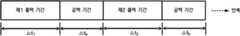
도 2는 출력 제어 수단(40)이 출력 제어를 수행하는 단위 주기를 나타낸 도면.2 shows a unit cycle in which the output control means 40 performs output control.
도 3은 본 발명의 제1 실시예에 따른 디스플레이 검사 장치(100)의 구성을 도시한 도면.3 is a diagram illustrating a configuration of a display inspection apparatus 100 according to a first embodiment of the present invention.
도 4는 단방향 반사 거울의 구조를 설명하는 도면.4 is a diagram illustrating a structure of a unidirectional reflective mirror.
도 5는 단방향 반사 거울을 이용하는 CD-ROM의 원리를 설명하는 도면.Fig. 5 illustrates the principle of a CD-ROM using a unidirectional reflective mirror.
도 6은 원 이미지와 거울에 반사된 이미지를 비교하는 도면.6 is a diagram comparing an original image with an image reflected in a mirror.
도 7은 본 발명의 제2 실시예에 따른 디스플레이 검사 장치(100)의 구성을 도시한 도면.7 is a diagram showing the configuration of a display inspection apparatus 100 according to a second embodiment of the present invention.
도 8은 본 발명의 일 실시예에 따른, 디스플레이 검사 장치(100)를 이용하여 화질 불량을 검사하는 방법을 나타내는 흐름도.8 is a flowchart illustrating a method of inspecting an image quality defect using the display inspection apparatus 100 according to an embodiment of the present invention.
(도면의 주요부분에 대한 부호 설명)(Symbol description of main part of drawing)
10 : 기준 디스플레이 패널 20 : 대상 디스플레이 패널10: reference display panel 20: target display panel
30 : 포커스 일치 수단40 : 출력 제어 수단30: focus matching means 40: output control means
50 : 메모리60 : 검사창50: memory 60: inspection window
70 : 단방향 반사 거울80a, 80b : 거울70: one-way
90 : 암실99 : 검사자90: dark room 99: inspector
본 발명은 디스플레이 패널 검사에 관한 것으로서, 보다 상세하게는 디스플레이 패널의 화질 불량을 육안으로 용이하게 식별할 수 있도록 하는 장치에 관한 것이다.BACKGROUND OF THE INVENTION 1. Field of the Invention The present invention relates to display panel inspection, and more particularly, to an apparatus for easily identifying visual quality defects of a display panel.
최근 들어, 정보통신의 비약적인 발전과 함께 디스플레이 장치의 수요도 폭발적으로 증가하고 있고, 이에 따라서, CRT(Cathode Ray Tube), LCD(Liquid Crystal Display), PDP(Plasma Display Panel) 등의 다양한 디스플레이의 생산도 증가하는 추세에 있다. 그런데, 현대의 소비자들은 디스플레이의 화소 불량 여부뿐만 아니라, 전체적인 화질 불량에도 민감하게 반응한다. 따라서, 디스플레이의 제조자에게는 디스플레이 화질 불량 여부를 정확하고 효율적으로 찾아내는 기술이 요구된다.Recently, with the rapid development of information and communication, the demand for display devices is exploding, and accordingly, various displays such as Cathode Ray Tube (CRT), Liquid Crystal Display (LCD), and Plasma Display Panel (PDP) are produced. Is also on the rise. However, modern consumers are sensitive not only to the pixel defect of the display but also to the overall image quality defect. Therefore, there is a demand for a manufacturer of a display to accurately and efficiently find out whether or not display quality is poor.
디스플레이 제조 공정 중에 발생할 수 있는 화질의 불량을 검사하는 방법으로는, 양품으로 판정된 디스플레이 패널과 검사 대상인 디스플레이 패널을 비교하는 방법이 주로 사용되고 있다. 그런데, 이러한 검사 방법에는 특정 전자 회로에 의하여 자동으로 검사하는 방법과, 육안에 의하여 화질 불량을 직접 검사하는 방법으로 나뉜다.As a method for inspecting a poor image quality that may occur during a display manufacturing process, a method of comparing a display panel determined as good quality and a display panel to be inspected is mainly used. However, these inspection methods are divided into a method of automatically inspecting by a specific electronic circuit and a method of directly inspecting image quality defects by the naked eye.
전자의 방법과 관련하여, 한국등록특허 192036호는 검사 대상인 패턴과 양품으로 판정된 패턴의 영상을 카메라로 획득하여 그 차이 값을 비교함으로써 디스플레이 패널의 불량 여부, 즉 디스플레이 패널에 불량 화소가 존재하는지 여부를 판정하는 방법을 게시하고 있다. 이와 같이 자동으로 화소의 불량을 찾아내는 방법은 매우 편리하고 객관적인 판정 기준을 제공한다는 장점이 있다.In relation to the former method, Korean Patent No. 192036 obtains an image of a pattern to be inspected and a pattern determined to be good by a camera and compares the difference value to determine whether the display panel is defective, that is, whether there are defective pixels on the display panel. Posts how to determine whether or not. As such, the method of automatically finding a pixel defect has an advantage of providing a very convenient and objective decision criterion.
그러나, 이와 같은 자동 검사 방법은 신속하고 편리하기는 하지만, 그 검출 가능한 불량의 종류가 점 형태의 화소 불량 등으로 국한되어 있는 것이 사실이다. 따라서, 현재 디스플레이 패널의 화질 불량 검사는 제조 공정의 마지막 단계에서 사람의 육안을 통해 이루어지는 경우가 많다. 왜냐하면, 자동 검사 장치로는 검출되지 않으나 사람의 육안으로 찾을 수 있는 화질 불량이 존재할 수 있기 때문에, 상당한 불편을 감수하고서라도 육안검사에 의존하고 있는 실정이다.However, although such an automatic inspection method is quick and convenient, it is true that the kind of detectable defects is limited to pixel defects in the form of dots. Therefore, current quality inspection of the display panel is often performed by the human eye at the end of the manufacturing process. This is because the image quality defects that are not detected by the automatic inspection device but can be found by the human eye may exist, and therefore, the user has resorted to the visual inspection even with considerable inconvenience.
그러나, 종래의 육안 검사 방법은, 검사자 개개인에게 의존하게 하므로 검사자에 따라 검사 결과가 다르게 나올 수 있는 문제가 있다. 또한, 육안으로 화질 불량을 검출하기가 쉽지 않기 때문에 화질 불량 검사시 검사자에게 많은 수고를 요하게 된다.However, the conventional visual inspection method is dependent on the individual inspector, there is a problem that the inspection results may be different for each inspector. In addition, since it is not easy to detect image quality defects with the naked eye, a lot of trouble is required for the inspector when examining image quality defects.
본 발명은 상기한 문제점을 고려하여 창안된 것으로, 육안 검사의 신뢰성을 높일 수 있는 디스플레이 검사 장치를 제공하는 것을 목적으로 한다.The present invention has been made in view of the above problems, and an object of the present invention is to provide a display inspection apparatus that can increase the reliability of visual inspection.
또한 본 발명은, 대상 디스플레이 패널의 화질 불량을 쉽게 찾을 수 있는 디스플레이 검사 장치를 제공하는 것을 목적으로 한다.In addition, an object of the present invention is to provide a display inspection device that can easily find a poor image quality of the target display panel.
본 발명에 따르면, 검사 기준에 따라서 검사 수율을 자유롭게 조절할 수 있는 디스플레이 검사 장치를 제공하는 것을 목적으로 한다.According to the present invention, it is an object of the present invention to provide a display inspection apparatus that can freely adjust the inspection yield in accordance with the inspection criteria.
상기한 목적을 달성하기 위하여, 본 발명에 따른 디스플레이 검사 장치는 제1 출력 기간 동안 샘플 이미지의 출력 신호를 수신하여 상기 출력 신호에 따른 기준 이미지를 표시하는 기준 디스플레이 패널; 상기 제1 출력 기간과 중복되지 않는 제2 출력 기간 동안 샘플 이미지의 출력 신호를 수신하여 상기 출력 신호에 따른 테스트 이미지를 표시하는 대상 디스플레이 패널; 상기 기준 이미지와 상기 테스트 이미지의 표시 위치 및 크기를 일치시키는 포커스 일치 수단; 및 상기 제1 출력 기간 동안에는 소정의 메모리에 저장된 샘플 이미지 신호를 상기 기준 디스플레이 패널로 출력하고, 상기 제2 출력 기간 동안에는 상기 샘플 이미지 신호를 상기 대상 디스플레이 패널로 출력하는 출력 제어 수단을 포함한다.In order to achieve the above object, the display inspection apparatus according to the present invention comprises a reference display panel for receiving an output signal of the sample image during the first output period and displaying a reference image according to the output signal; A target display panel configured to receive an output signal of a sample image and display a test image according to the output signal during a second output period that does not overlap with the first output period; Focus matching means for matching a display position and a size of the reference image and the test image; And output control means for outputting a sample image signal stored in a predetermined memory to the reference display panel during the first output period, and outputting the sample image signal to the target display panel during the second output period.
상기 출력 제어 수단은 제1 출력 기간 동안에는 상기 대상 디스플레이 패널이 공백 화면을 표시하도록 제어하고, 제2 출력 기간 동안에는 상기 기준 디스플레이 패널이 공백 화면을 표시하도록 제어하는 것이 바람직하다.Preferably, the output control means controls the target display panel to display a blank screen during a first output period, and controls the reference display panel to display a blank screen during a second output period.
또한, 상기 출력 제어 수단은 상기 제1 출력 기간과 제2 출력 기간 사이에 공백 기간을 설정하고, 상기 공백 기간 동안에는 상기 출력 제어 수단은 상기 기준 디스플레이 패널과 대상 디스플레이 패널이 공백 화면을 표시하도록 제어하는 것이 바람직하다.The output control means may set a blank period between the first output period and the second output period, and during the blank period, the output control means controls the reference display panel and the target display panel to display a blank screen. It is preferable.
상기 공백 기간을 변경함으로써 검사 수율을 조절하는 것이 바람직하다.It is desirable to adjust the inspection yield by changing the blank period.
상기 포커스 일치 수단은, 일측면은 빛을 반사하고 다른 측면은 빛을 투과하는 단방향 반사 거울을 포함하는데, 상기 단방향 반사 거울은, 상기 기준 디스플레이 패 널의 화면 및 상기 대상 디스플레이 패널의 화면과 각각 실질적인 45도를 이루는 것이 바람직하다.The focus matching means includes a unidirectional reflecting mirror that reflects light on one side and transmits light on the other side, wherein the unidirectional reflecting mirror is substantially equivalent to the screen of the reference display panel and the screen of the target display panel, respectively. It is desirable to achieve 45 degrees.
상기 기준 디스플레이 패널은 상기 빛을 투과하는 측면을 향하도록 배치되고, 상기 대상 디스플레이 패널은 상기 빛을 반사하는 측면을 향하도록 배치되는 것이 바람직하다.The reference display panel is disposed to face the side that transmits the light, and the target display panel is disposed to face the side that reflects the light.
상기 대상 디스플레이 패널의 화면으로부터 상기 단방향 반사 거울의 반사면까지의 거리 및 상기 기준 디스플레이 패널의 화면으로부터 상기 단방향 반사 거울의 투과면까지의 거리가 동일한 것이 바람직하다.Preferably, the distance from the screen of the target display panel to the reflective surface of the unidirectional reflective mirror and the distance from the screen of the reference display panel to the transmissive surface of the unidirectional reflective mirror are the same.
상기 출력 제어 수단이 상기 대상 디스플레이 패널로 출력하는 신호는 상기 샘플 이미지를 좌우 대칭한 이미지의 신호인 것이 바람직하다.Preferably, the signal output by the output control means to the target display panel is a signal of an image in which the sample image is symmetrical with respect to the sample image.
한편, 상기 포커스 일치 수단은, 상기 서로 마주보는 방향으로 배치된 기준 디스플레이 패널 및 대상 디스플레이 패널이 제공하는 이미지를 각각 반사하여 검사자에게 제공하는 복수의 거울을 포함하는 것이 바람직하다.On the other hand, the focus matching means, it is preferable to include a plurality of mirrors for reflecting the image provided by the reference display panel and the target display panel disposed in the direction facing each other to provide to the inspector.
상기 복수의 거울은 상기 기준 디스플레이 패널 및 상기 대상 디스플레이 패널을 향하여 각각 실질적인 45도를 이루는 것이 바람직하다.The plurality of mirrors preferably form substantially 45 degrees toward the reference display panel and the target display panel, respectively.
이하, 첨부된 도면을 참조하여 본 발명의 바람직한 실시예를 상세히 설명한다. 본 발명의 이점 및 특징, 그리고 그것들을 달성하는 방법은 첨부되는 도면과 함께 상세하게 후술되어 있는 실시예들을 참조하면 명확해질 것이다. 그러나 본 발명은 이하에서 개시되는 실시예들에 한정되는 것이 아니라 서로 다른 다양한 형태로 구현될 것이며, 단지 본 실시예들은 본 발명의 개시가 완전하도록 하며, 본 발명이 속 하는 기술분야에서 통상의 지식을 가진 자에게 발명의 범주를 완전하게 알려주기 위해 제공되는 것이며, 본 발명은 청구항의 범주에 의해 정의될 뿐이다. 명세서 전체에 걸쳐 동일 참조 부호는 동일 구성 요소를 지칭한다.Hereinafter, exemplary embodiments of the present invention will be described in detail with reference to the accompanying drawings. Advantages and features of the present invention and methods for achieving them will be apparent with reference to the embodiments described below in detail with the accompanying drawings. However, the present invention is not limited to the embodiments disclosed below, but may be implemented in various different forms, only the embodiments are to make the disclosure of the present invention complete, and common knowledge in the art to which the present invention belongs It is provided to fully inform the person having the scope of the invention, which is defined only by the scope of the claims. Like reference numerals refer to like elements throughout.
본 발명은 "숨은 그림 찾기" 등과 같이 유사한 두 개의 영상에서 차이 나는 일부분을 검출하고자 할 때, 두 영상을 겹쳐서 빠른 속도로 번갈아 보여주면 차이점이 두드러져 보이는 원리를 이용한다. 따라서, 본 발명은 기준 디스플레이 패널(양품으로 판정된 디스플레이 패널)과 검사 디스플레이 패널을 광학적 또는 기구적인 장치를 이용하여 일정한 속도로 번갈아 보여준다. 그 결과, 검사자가 디스플레이 패널의 화질 불량 부분을 쉽게 찾아 낼 수 있도록 한다. 다만, 검사자가 볼 때의 기준 디스플레이 패널의 화면과 검사 디스플레이 패널의 화면은 동일한 크기의 동일한 위치여야 한다.The present invention utilizes the principle that the difference is prominent when the two images are alternately displayed at high speed when the two portions are to be detected to be different from each other in a similar image such as "find hidden picture". Accordingly, the present invention alternately shows the reference display panel (good judged display panel) and the test display panel at a constant speed using an optical or mechanical device. As a result, the inspector can easily find out the poor quality of the display panel. However, the screen of the reference display panel and the screen of the test display panel as viewed by the inspector should be the same position of the same size.
도 1은 본 발명에 따른 디스플레이 검사 장치(100)의 개략적 구성을 도시한 블록도이다. 디스플레이 검사 장치(100)는 기준 디스플레이 패널(10), 대상 디스플레이 패널(20), 포커스 일치 수단(30), 출력 제어 수단(40), 및 메모리(50)를 포함하여 구성될 수 있다.1 is a block diagram showing a schematic configuration of a display inspection apparatus 100 according to the present invention. The display inspection apparatus 100 may include a
기준 디스플레이 패널(10)은 양품임으로 판정된 디스플레이 패널로서, 제1 출력 기간(기준 디스플레이 패널로의 출력 기간) 동안 출력 제어 수단(40)로부터 샘플 이미지의 출력 신호를 수신하여 상기 출력 신호에 따른 기준 이미지를 표시한다. 그리고, 대상 디스플레이 패널(20)은 검사 대상이 되는 디스플레이로서, 상기 제1 출력 기간과 중복되지 않는(즉, 중복되는 기간이 존재하지 않는) 제2 출력 기간(대상 디스플레이 패널로의 출력 기간) 동안 출력 제어 수단(40)으로부터 샘플 이미지의 출력 신호를 수신하여 테스트 이미지를 표시한다.The
여기서, "기준 이미지"라 함은 메모리(50)에 저장된 샘플 이미지의 신호를 입력 받아 기준 디스플레이 패널(10)의 화면에 실제로 표시되는 영상을 의미하고, "테스트 이미지"라 함은 상기 샘플 이미지의 신호를 입력 받아 대상 디스플레이 패널(20)의 화면에 실제로 표시되는 영상을 의미한다.Here, the "reference image" refers to an image that is actually displayed on the screen of the
포커스 일치 수단(30)은 기준 디스플레이 패널(10)에 의하여 표시되는 기준 이미지와 대상 디스플레이 패널(20)에 의하여 표시되는 테스트 이미지의 표시 위치 및 크기(이하 '포커스'라 함)가 일치되도록 한다. 포커스 일치 수단(30)은 후술하는 몇 개의 실시예에 따라서 그 구체적인 구성이 도시된다.The focus matching means 30 causes the display position and size (hereinafter referred to as 'focus') of the reference image displayed by the
그리고, 출력 제어 수단(40)은 메모리(50)에 저장된 샘플 이미지의 신호를, 제1 출력 기간 동안에는 기준 디스플레이 패널(10)로 출력되도록 제어하고, 제2 출력 기간 동안에는 대상 디스플레이 패널(20)로 출력되도록 제어한다. 이 때, 신호를 출력하지 않을 패널은 공백 화면을 표시하게 한다. 본 명세서에서 패널이 공백 화면을 표시한다는 것은, 출력 제어 수단(40)이 특정 패널로 이미지 신호의 출력을 차단하거나, 특정 패널의 전원을 차단하거나, 또는 특정 패널에 대비 이미지를 출력하는 것 등을 의미할 수 있다.The output control means 40 controls the signal of the sample image stored in the
여기서 "대비 이미지"라 함은 소정의 단색 이미지를 의미하는데, 바람직하게는 상기 단색의 색상으로는 기준 디스플레이 패널과 대상 디스플레이 패널에 나타나는 이미지에 분포하는 색상 이외의 색상을 사용하는 것이 바람직할 것이다. 일반적으 로 대부분의 이미지에는 "white 색상"이 잘 나타나지 않으므로 상기 대비 이미지로는 흰색 이미지를 사용하는 것이 바람직하다.Here, the term "contrast image" means a predetermined monochrome image. Preferably, the monochromatic color may be a color other than the color distributed in the image displayed on the reference display panel and the target display panel. In general, most images do not show a "white color" well, so it is preferable to use a white image as the contrast image.
출력 제어 수단(40)은 상기 제1 출력 기간 및 제2 출력 기간 사이에 소정 크기의 공백 기간을 위치시킬 수도 있다. 도 2는 출력 제어 수단(40)이 출력 제어를 수행하는 단위 주기를 나타낸 도면이다. 단위 주기는 제1 출력 기간(Δt1)과, 공백 기간(Δtb)과, 제2 출력 기간(Δt2)과, 공백 기간(Δtb)으로서 구성되며, 상기 단위 주기가 계속하여 반복된다.The output control means 40 may place a blank period of a predetermined size between the first output period and the second output period. 2 is a diagram illustrating a unit cycle in which the output control means 40 performs output control. The unit period is configured as a first output period Δt1 , a blank period Δtb , a second output period Δt2 , and a blank period Δtb , and the unit cycle is repeated continuously.
여기서 제1 출력 기간과 제2 출력 기간은 다르게 유지할 수도 있지만, 같도록 유지하는 것이 바람직하다. 제1 출력 기간 및 제2 출력 기간은 대략 100 내지 500 밀리초 정도를 유지하는 것이 바람직하며, 공백 기간은 0 내지 60 밀리초 정도를 유지하는 것이 바람직하다. 검사자(99)는 필요에 따라 출력 제어 수단(40)을 조작함으로써 제1 출력 기간, 제2 출력 기간, 및 공백 기간을 변경할 수 있다.Here, although the first output period and the second output period may be kept different, it is preferable to keep them the same. The first output period and the second output period are preferably maintained at about 100 to 500 milliseconds, and the blank period is preferably maintained at about 0 to 60 milliseconds. The
검사자(99)는 공백 기간을 변경함으로써 불량률 검출 정도를 조절할 수 있다. 왜냐하면, 공백 기간이 짧을수록 기준 디스플레이 패널(10)과 대상 디스플레이 패널(20)이 생성하는 이미지 간의 차이에 민감하게 되어, 불량 픽셀을 검출할 가능성이 높아지기 때문이다. 따라서, 공백 기간을 조절함으로써, 검사 수율(전체 대상 디스플레이 패널들 중 양호한 것으로 판정되는 비율)의 조절이 가능하다.The
출력 제어 수단(40)은 제1 출력 기간 동안에는 기준 디스플레이 패널(10)로만 샘플 이미지의 신호가 입력되도록 하고, 대상 디스플레이 패널(20)로는 샘플 이미지의 신호가 입력되지 않도록 한다. 물론, 대상 디스플레이 패널(20)로 샘플 이미지의 신호가 입력되지 않도록 하는 것은, 대상 디스플레이 패널(20)의 전원을 차단하는 것에 의하여도 동일한 결과를 얻을 수 있을 것이다.The output control means 40 allows the signal of the sample image to be input only to the
마찬가지로, 출력 제어 수단(40)은 제2 출력 기간 동안에는 기준 디스플레이 패널(20)로만 샘플 이미지의 신호가 입력되도록 하고, 대상 디스플레이 패널(10)로는 샘플 이미지의 신호가 입력되지 않도록 한다.Similarly, the output control means 40 allows the signal of the sample image to be input only to the
상기 공백 기간(Δtb)은 기준 디스플레이 패널(10) 및 대상 디스플레이 패널(20) 모두 "공백 화면"을 표시하지 않는 시간을 의미하는 것이다. 출력 제어 수단(40)은 일반적인 컴퓨터나, 별도로 제작된 마이컴(micro computer), 하드웨어 모듈 등에 의하여 구현될 수 있다.The blank period Δtb means a time when neither the
한편, 메모리(50)는 샘플 이미지를 저장하는 저장 매체로서, 출력 제어 수단(40)의 내부에 포함되거나, 외부에 별도로 존재할 수 있다.On the other hand, the
도 3은 본 발명의 제1 실시예에 따른 디스플레이 검사 장치(100)의 구성을 도시한 도면이다. 도 3에서 보는 바와 같이, 기준 디스플레이 패널(10)이 향하는 방향과 대상 디스플레이 패널(20)이 향하는 방향은 서로 90도가 되도록 한다.3 is a diagram illustrating a configuration of the display inspection apparatus 100 according to the first embodiment of the present invention. As shown in FIG. 3, the direction that the
여기서, 포커스 일치 수단(30)은 적어도, 단방향 반사 거울(70)을 포함하며, 검사창(60) 및 암실(90)을 더 포함할 수 있다.Here, the focus matching means 30 includes at least a unidirectional
단방향 반사 거울(one-way mirror; 70)는 도 4에 도시하는 바와 같이, 한쪽 면(반사면; 72)은 거울처럼 빛을 반사하며, 다른 한쪽 면(투과면; 71)에서는 일반 유리 처럼 빛을 투과하는 특성을 지니는 복층 유리이다. 단방향 반사 거울(70)은 현재 CD-ROM이나 See-through 타입의 HMD(Head Mounted Display) 등 정밀을 요하는 기기에 사용되고 있다.As shown in Fig. 4, one-
예를 들어, 단방향 반사 거울을 이용하는 CD-ROM의 구조는 도 5에 도시하는 바와 같다. 레이저 발생기에서 발생된 레이저는 단방향 반사거울 및 렌즈들을 통과하여 광디스크의 표면에 도달하여 반사되고, 광디스크에서 반사된 레이저는 단방향 반사거울에서 반사되어 레이저 발생기에 대하여 직각 위치에 있는 광 감지기에 도달하게 되고 최종적으로 상기 광디스크 표면에 나타난 값을 읽게 된다. 이와 같은 종래의 기술들에서도 단방향 반사 거울을 이용하여 정확한 위치에 광 출력을 제공하는 방법들이 응용되어 왔다.For example, the structure of a CD-ROM using a unidirectional reflecting mirror is as shown in FIG. The laser generated from the laser generator passes through the unidirectional reflective mirror and the lenses to reach the surface of the optical disc and is reflected thereon, and the laser reflected from the optical disc is reflected from the unidirectional reflective mirror to reach the light detector at a position perpendicular to the laser generator. Finally, the value shown on the surface of the optical disc is read. Such conventional techniques have also been applied to provide light output at an accurate position using a unidirectional reflective mirror.
다시 도 3으로 돌아가면, 단방향 반사 거울(70)은 기준 디스플레이 패널(10)의 화면 및 대상 디스플레이 패널(20)의 화면과 각각 약 45도(실질적인 45도)가 되는 방향으로 설치된다. 이 때, 기준 디스플레이 패널(10)은 단방향 반사 거울(70)의 투과면 측을 향하도록 배치되고, 대상 디스플레이 패널(20)은 단방향 반사 거울(70)의 반사면 측을 향하도록 배치된다. 이와 같이 하면 대상 디스플레이 패널(20)을 검사자(99)의 측면에 위치하게 할 수 있다. 다만, 이는 하나의 실시예에 불과하고 기준 디스플레이 패널(10)과 대상 디스플레이 패널(20)의 위치를 바꾸어 설치할 수도 있다.3, the unidirectional
검사창(60)은 검사자(99)가 단방향 반사 거울(70)에 맺힌 이미지를 관찰하는 창으로서, 검사자의 눈높이나 조도 등의 검사환경을 조절할 수 있다. 그리고, 검사창 (60)의 내부는 암실(90)로 되어 있는데, 이러한 암실(90)은 패널(10, 20)에서 제공하는 이미지 외에 다른 외부의 빛을 차단한다.The
검사자(99)가 화질 불량을 판단하기 위해서는, 관측하는 기준 이미지와 대상 이미지의 표시 위치 및 크기가 일치하여야 하는데, 상기 크기를 일치시키기 위해서는 패널(10, 20)로부터 검사창(60)에 빛이 도달하는 거리를 같게 하여야 한다. 따라서, 대상 디스플레이 패널(20)의 화면으로부터 단방향 반사 거울(70)의 반사면(72)까지의 거리(d1)와, 기준 디스플레이 패널(10)의 화면으로부터 단방향 반사 거울(70)의 투과면(71)까지의 거리(d2)가 같도록 한다.In order for the
제1 실시예에서, 주의할 것은 만일, 기준 디스플레이 패널(10) 및 대상 디스플레이 패널(20)에 표시되는 영상이 도 6의 원 이미지(1A)와 같다고 할 때, 기준 디스플레이 패널(10)에 의해 생성되어 단방향 반사 거울(70)을 투과되는 기준 이미지는 원 이미지(1A)와 같지만, 대상 디스플레이 패널(20)에 의해 생성되어 단방향 반사 거울(70)에서 반사되는 테스트 이미지는 원 이미지에서 좌우가 바뀐 이미지(2B)가 된다.In the first embodiment, it should be noted that when the image displayed on the
따라서, 제1 실시예에서 출력 제어 수단(40)은, 제1 출력 기간 동안에는 샘플 이미지의 신호를 기준 디스플레이 패널(10)로 그대로 출력하지만, 제2 출력 기간 동안에는 샘플 이미지를 좌우 대칭한 이미지의 신호를 대상 디스플레이 패널(20)로 출력한다. 이와 같이 함으로써, 기준 디스플레이 패널(10)로부터 검사창(60)에 제공되는 이미지 및 대상 디스플레이 패널(20)로부터 검사창(60)에 제공되는 이미지가 동일한 방향을 가질 수 있다.Therefore, in the first embodiment, the output control means 40 outputs the signal of the sample image to the
한편, 제1 실시예에서 사용한 단방향 반사 거울 대신에, 최근에 'Electrochromic mirror' 또는 'Switchable mirror'로 불리는 가변 거울을 이용하는 실시예도 생각할 수도 있다. 이러한, 가변 거울은 전압 인가에 따라 유리의 투과 및 반사 특성이 전환되는 특성이 있다. 따라서, 상기 가변 거울을 도 3의 단방향 반사 거울(70)과 같은 위치에 두고 전압 인가를 조절하면 단방향 반사 거울(70)과 같은 효과를 얻을 수 있다.On the other hand, instead of the unidirectional reflective mirror used in the first embodiment, an embodiment using a variable mirror recently called an 'Electrochromic mirror' or a 'Switchable mirror' may also be considered. Such a variable mirror has a characteristic that the transmission and reflection characteristics of the glass are switched according to the application of voltage. Therefore, when the variable mirror is positioned at the same position as the unidirectional
예를 들어, 사용자는 제1 출력 기간 동안에는 상기 가변 거울이 유리로 동작하도록 하는 제1 전압을 인가하고, 제2 출력 기간 동안에는 상기 가변 거울이 거울로 동작하도록 하는 제2 전압을 인가하면 될 것이다.For example, a user may apply a first voltage for causing the variable mirror to act as glass during a first output period and a second voltage for causing the variable mirror to act as a mirror during a second output period.
도 7은 본 발명의 제2 실시예에 따른 디스플레이 검사 장치(100)의 구성을 도시한 도면이다. 제2 실시예는 제1 실시예와 달리 단방향 반사 거울(70)을 사용하지 않고 단순히 두 개의 거울(80a, 80b)을 사용하며, 기준 디스플레이 패널(10)과 대상 디스플레이 패널(20)을 서로 마주 보도록 배치한다.FIG. 7 is a diagram illustrating a configuration of a display inspecting apparatus 100 according to a second exemplary embodiment of the present invention. Unlike the first embodiment, the second embodiment does not use the unidirectional reflecting
이러한 구조로부터, 상기 거울(80a, 80b)은 상기 서로 마주보는 방향으로 배치된 기준 디스플레이 패널 및 대상 디스플레이 패널이 제공하는 이미지를 각각 반사하여 검사자(99)에게 제공할 수 있다. 즉, 기준 디스플레이 패널(10)에서 생성되는 기준 이미지는 제1 거울(80a)에 의하여 반사되어 검사창(60)에 투영되고, 대상 디스플레이 패널(20)에서 생성되는 테스트 이미지는 제2 거울(80b)에 의하여 반사되어 검사창(60)에 투영된다. 물론, 기준 이미지와 테스트 이미지의 표시 위치 및 크 기가 일치하도록 제1 거울(80a) 및 제2 거울(80b)의 각도를 적절히 조절한다. 상기 복수의 거울(80a, 80b)는 대략 상기 기준 디스플레이 패널 및 상기 대상 디스플레이 패널을 향하여 각각 실질적인 45도를 이루도록 구성될 수 있다.From this structure, the
제2 실시예는 제1 실시예와는 달리 기준 디스플레이 패널(10)로부터 제공되는 영상 및 대상 디스플레이 패널(20)로부터 제공되는 영상이 각각 거울(80a, 80b)에 의하여 반사되므로, 반사되어 검사창(60)에 투영된 이미지의 좌우가 서로 일치된다. 그렇기는 하지만, 검사창(60)에 투영된 이미지는 원 샘플 이미지와는 좌우가 대칭으로 되므로, 이를 보정하기 위하여 출력 제어 수단(40)은, 샘플 이미지를 좌우 대칭한 이미지의 신호를 기준 디스플레이 패널(10) 및 대상 디스플레이 패널(20)에 제공하는 것이 바람직하다.Unlike the first embodiment, since the image provided from the
도 8은 본 발명의 일 실시예에 따른, 디스플레이 검사 장치(100)를 이용하여 화질 불량을 검사하는 방법을 나타내는 흐름도이다.8 is a flowchart illustrating a method of inspecting poor image quality using the display inspection apparatus 100 according to an exemplary embodiment.
검사 조명 및 검사자 눈높이 등의 검사 환경을 조절한다(S1). 그리고, 기준 디스플레이 패널(10), 대상 디스플레이 패널(20), 및 출력 제어 수단(40), 및 포커스 일치 수단(30)을 장착하고 구동한다(S2). 검사자(99)는 출력 제어 수단(40)을 통하여 제1 출력 기간, 공백 기간, 및 제2 출력 기간을 설정한다(S3). 이 경우 제1 출력 기간 및 제2 출력 기간은 동일하게 설정하도록 하며, 공백 기간은 검사 수율에 따라서 적절한 값을 설정한다(검사 수율을 높이려면 공백 기간을 증가시킨다).Control the inspection environment, such as inspection lighting and the eye level of the examiner (S1). Then, the
다음은, 출력 제어 수단(40)은 제1 출력 기간 동안, 즉 제1 출력 기간이 만료되기 전 동안(S5의 아니오) 기준 디스플레이 패널(10)로 샘플 이미지를 출력하고, 대상 디스플레이 패널(20)에는 공백 화면을 표시한다(S4).Next, the output control means 40 outputs the sample image to the
제1 출력 기간이 만료된 후(S5의 예), 공백 기간이 0이 아닌 값으로 설정되어 있으면(S6의 아니오) 공백 기간 동안(S8의 아니오) 기준 디스플레이 패널(10) 및 대상 디스플레이 패널(20)에 공백 화면을 표시한다(S7). 그리고, 공백 기간이 0으로 설정되어 있으면(S6의 예) 바로 S9 단계로 진행한다.After the first output period has expired (YES in S5), if the blanking period is set to a nonzero value (NO in S6) during the blanking period (NO in S8), the
다음, 출력 제어 수단(40)은 제2 출력 기간 동안(S10의 아니오) 대상 디스플레이 패널(20)로 샘플 이미지를 출력하고, 기준 디스플레이 패널(10)에는 공백 화면을 표시한다(S9).Next, the output control means 40 outputs the sample image to the
이후, 양/불량 여부를 판정할 정도로 반복 횟수의 수행이 완료되면(S11의 예), 검사자는 대상 디스플레이 패널(20)의 양/불량을 판정하고(S12) 검사 결과를 대상 디스플레이 패널의 고유번호와 함께 저장한다(S13).Subsequently, when the execution of the number of repetitions is completed to determine whether it is good or bad (YES in S11), the inspector determines the good or bad of the target display panel 20 (S12), and the test result is a unique number of the target display panel. Store with (S13).
S11 단계에서, 반복 횟수 수행이 완료되지 않으면(S11의 아니오), 다시 공백 기간 동안(S15의 아니오) 기준 디스플레이 패널(10) 및 대상 디스플레이 패널(20)에 공백 화면을 표시한다(S7). 물론 공백 기간이 0으로 설정되어 있다면(S14의 예) 바로 S4 단계로 진행하게 될 것이다.In step S11, if the number of repetitions is not completed (NO in S11), a blank screen is displayed on the
이상 첨부된 도면을 참조하여 본 발명의 실시예를 설명하였지만, 본 발명이 속하는 기술분야에서 통상의 지식을 가진 자는 본 발명이 그 기술적 사상이나 필수적인 특징을 변경하지 않고서 다른 구체적인 형태로 실시될 수 있다는 것을 이해할 수 있을 것이다. 그러므로 이상에서 기술한 실시예들은 모든 면에서 예시적인 것이며 한정적이 아닌 것으로 이해해야 한다.Although embodiments of the present invention have been described above with reference to the accompanying drawings, those skilled in the art to which the present invention pertains may implement the present invention in other specific forms without changing the technical spirit or essential features thereof. I can understand that. Therefore, it should be understood that the embodiments described above are exemplary in all respects and not restrictive.
본 발명에 따르면, 기준 디스플레이 패널과 대상 디스플레이 패널을 실시간으로 비교할 수 있기 때문에 육안 검사의 신뢰성을 높일 수 있다.According to the present invention, since the reference display panel and the target display panel can be compared in real time, the reliability of visual inspection can be improved.
본 발명에 따르면, 대상 디스플레이 패널의 화질 불량을 쉽게 찾을 수 있어 검사 능률을 높일 수 있다.According to the present invention, it is possible to easily find a poor image quality of the target display panel, thereby increasing the inspection efficiency.
또한, 본 발명에 따르면, 공백 기간을 조절하여 검사 기준에 따라서 검사 수율을 자유롭게 조절할 수 있다.In addition, according to the present invention, it is possible to freely adjust the inspection yield in accordance with the inspection criteria by adjusting the blank period.
Claims (15)
Translated fromKoreanPriority Applications (2)
| Application Number | Priority Date | Filing Date | Title |
|---|---|---|---|
| KR1020040099947AKR100703694B1 (en) | 2004-12-01 | 2004-12-01 | Display inspection device |
| US11/283,703US20060114525A1 (en) | 2004-12-01 | 2005-11-22 | Apparatus and method for inspecting a display |
Applications Claiming Priority (1)
| Application Number | Priority Date | Filing Date | Title |
|---|---|---|---|
| KR1020040099947AKR100703694B1 (en) | 2004-12-01 | 2004-12-01 | Display inspection device |
Publications (2)
| Publication Number | Publication Date |
|---|---|
| KR20060061080A KR20060061080A (en) | 2006-06-07 |
| KR100703694B1true KR100703694B1 (en) | 2007-04-05 |
Family
ID=36567092
Family Applications (1)
| Application Number | Title | Priority Date | Filing Date |
|---|---|---|---|
| KR1020040099947AExpired - Fee RelatedKR100703694B1 (en) | 2004-12-01 | 2004-12-01 | Display inspection device |
Country Status (2)
| Country | Link |
|---|---|
| US (1) | US20060114525A1 (en) |
| KR (1) | KR100703694B1 (en) |
Cited By (2)
| Publication number | Priority date | Publication date | Assignee | Title |
|---|---|---|---|---|
| KR101256369B1 (en) | 2012-05-15 | 2013-04-25 | (주) 에스엘테크 | Flat display pannel test equipment and test method using multi ccd camera |
| CN108139336A (en)* | 2015-12-17 | 2018-06-08 | 日本电气硝子株式会社 | The manufacturing method of glass plate |
Families Citing this family (6)
| Publication number | Priority date | Publication date | Assignee | Title |
|---|---|---|---|---|
| US20090123897A1 (en)* | 2007-11-13 | 2009-05-14 | Janet Shangle | System, method and article of manufacture for entertaining, educating and soothing patient awake during dental or medical procedure |
| US8761938B2 (en)* | 2008-04-18 | 2014-06-24 | David Jenkinson | Robotic device tester |
| US10120474B2 (en)* | 2010-12-09 | 2018-11-06 | T-Mobile Usa, Inc. | Touch screen testing platform for engaging a dynamically positioned target feature |
| EP3482192A4 (en)* | 2016-07-08 | 2020-08-05 | ATS Automation Tooling Systems Inc. | SYSTEM AND PROCEDURE FOR COMBINED AUTOMATIC AND MANUAL INSPECTION |
| US10460638B2 (en)* | 2017-04-26 | 2019-10-29 | Honeywell International Inc. | Intermittent display issue monitoring system |
| KR102326955B1 (en)* | 2020-04-10 | 2021-11-16 | 주식회사 뷰웍스 | Analysis system for display device and color analysis method thereof |
Citations (2)
| Publication number | Priority date | Publication date | Assignee | Title |
|---|---|---|---|---|
| JPS5575617A (en) | 1978-12-04 | 1980-06-07 | Fujitsu Ltd | Test method for display unit |
| JPH085509A (en)* | 1994-06-21 | 1996-01-12 | Sharp Corp | Light-transmissive display panel inspection device |
Family Cites Families (3)
| Publication number | Priority date | Publication date | Assignee | Title |
|---|---|---|---|---|
| US5374940A (en)* | 1991-06-04 | 1994-12-20 | The University Of Rochester | System for operating a plurality of graphics displays from a single computer |
| US5568012A (en)* | 1994-08-22 | 1996-10-22 | Noritake Co., Limited | Fluorescent display tube wherein grid electrodes are formed on ribs contacting fluorescent segments, and process of manufacturing the display tube |
| KR100192036B1 (en)* | 1995-11-22 | 1999-06-15 | 손욱 | Lcd panel test system |
- 2004
- 2004-12-01KRKR1020040099947Apatent/KR100703694B1/ennot_activeExpired - Fee Related
- 2005
- 2005-11-22USUS11/283,703patent/US20060114525A1/ennot_activeAbandoned
Patent Citations (2)
| Publication number | Priority date | Publication date | Assignee | Title |
|---|---|---|---|---|
| JPS5575617A (en) | 1978-12-04 | 1980-06-07 | Fujitsu Ltd | Test method for display unit |
| JPH085509A (en)* | 1994-06-21 | 1996-01-12 | Sharp Corp | Light-transmissive display panel inspection device |
Cited By (3)
| Publication number | Priority date | Publication date | Assignee | Title |
|---|---|---|---|---|
| KR101256369B1 (en) | 2012-05-15 | 2013-04-25 | (주) 에스엘테크 | Flat display pannel test equipment and test method using multi ccd camera |
| CN108139336A (en)* | 2015-12-17 | 2018-06-08 | 日本电气硝子株式会社 | The manufacturing method of glass plate |
| CN108139336B (en)* | 2015-12-17 | 2021-08-24 | 日本电气硝子株式会社 | Method for manufacturing glass plate |
Also Published As
| Publication number | Publication date |
|---|---|
| US20060114525A1 (en) | 2006-06-01 |
| KR20060061080A (en) | 2006-06-07 |
Similar Documents
| Publication | Publication Date | Title |
|---|---|---|
| US5805243A (en) | Liquid crystal projector using a spatial light modulator and two rotating color filters | |
| US20030215129A1 (en) | Testing liquid crystal microdisplays | |
| US7384157B2 (en) | Projection type video display | |
| US10169855B2 (en) | Method and device for detecting defects on a display subtrate | |
| US5619284A (en) | Beam combiner for LCD projector utilizing a penta-prism | |
| KR100703694B1 (en) | Display inspection device | |
| JP3316501B2 (en) | Sensor head, luminance distribution measuring device including the same, and display unevenness evaluation device | |
| US5357288A (en) | Liquid crystal projector and method of projecting image | |
| US20130181109A1 (en) | Optical scanning projection module | |
| CN105915870A (en) | Automatic focusing apparatus and method of projector | |
| US7543944B2 (en) | Projection-type display apparatus and multiscreen display apparatus | |
| JP2003005130A (en) | 3D image display device | |
| CN110031481B (en) | Square wave structured light illumination implementation method based on polarization | |
| US12220168B2 (en) | Chart projector for testing visual acuity | |
| JP3520752B2 (en) | Liquid crystal panel inspection device, liquid crystal panel inspection method, and projection display device | |
| JP2010008188A (en) | Apparatus of inspecting display panel, inspection method, and method of manufacturing display panel using it | |
| JP2740593B2 (en) | Light transmissive liquid crystal display panel inspection equipment | |
| US20240203308A1 (en) | Method and system for detecting visual artefact of near-eye display | |
| KR0174940B1 (en) | Method for inspecting the projector in ama | |
| JP2009145106A (en) | Display defect evaluation apparatus and display defect evaluation method | |
| JP2005189324A (en) | projector | |
| US9164043B2 (en) | Detecting method and detecting device | |
| KR0174941B1 (en) | Apparatus for inspecting the projector in ama | |
| US20240194157A1 (en) | Drive circuit of display panel, display device, and drive method of display panel | |
| KR100421213B1 (en) | Laser Video Projection System for Large-Area Display |
Legal Events
| Date | Code | Title | Description |
|---|---|---|---|
| A201 | Request for examination | ||
| PA0109 | Patent application | St.27 status event code:A-0-1-A10-A12-nap-PA0109 | |
| PA0201 | Request for examination | St.27 status event code:A-1-2-D10-D11-exm-PA0201 | |
| PN2301 | Change of applicant | St.27 status event code:A-3-3-R10-R13-asn-PN2301 St.27 status event code:A-3-3-R10-R11-asn-PN2301 | |
| PN2301 | Change of applicant | St.27 status event code:A-3-3-R10-R13-asn-PN2301 St.27 status event code:A-3-3-R10-R11-asn-PN2301 | |
| D13-X000 | Search requested | St.27 status event code:A-1-2-D10-D13-srh-X000 | |
| PG1501 | Laying open of application | St.27 status event code:A-1-1-Q10-Q12-nap-PG1501 | |
| D14-X000 | Search report completed | St.27 status event code:A-1-2-D10-D14-srh-X000 | |
| E902 | Notification of reason for refusal | ||
| PE0902 | Notice of grounds for rejection | St.27 status event code:A-1-2-D10-D21-exm-PE0902 | |
| P11-X000 | Amendment of application requested | St.27 status event code:A-2-2-P10-P11-nap-X000 | |
| P13-X000 | Application amended | St.27 status event code:A-2-2-P10-P13-nap-X000 | |
| E701 | Decision to grant or registration of patent right | ||
| PE0701 | Decision of registration | St.27 status event code:A-1-2-D10-D22-exm-PE0701 | |
| GRNT | Written decision to grant | ||
| PR0701 | Registration of establishment | St.27 status event code:A-2-4-F10-F11-exm-PR0701 | |
| PR1002 | Payment of registration fee | St.27 status event code:A-2-2-U10-U11-oth-PR1002 Fee payment year number:1 | |
| PG1601 | Publication of registration | St.27 status event code:A-4-4-Q10-Q13-nap-PG1601 | |
| LAPS | Lapse due to unpaid annual fee | ||
| PC1903 | Unpaid annual fee | St.27 status event code:A-4-4-U10-U13-oth-PC1903 Not in force date:20100330 Payment event data comment text:Termination Category : DEFAULT_OF_REGISTRATION_FEE | |
| PC1903 | Unpaid annual fee | St.27 status event code:N-4-6-H10-H13-oth-PC1903 Ip right cessation event data comment text:Termination Category : DEFAULT_OF_REGISTRATION_FEE Not in force date:20100330 | |
| R18-X000 | Changes to party contact information recorded | St.27 status event code:A-5-5-R10-R18-oth-X000 | |
| P22-X000 | Classification modified | St.27 status event code:A-4-4-P10-P22-nap-X000 |