KR100703160B1 - Display device - Google Patents
Display deviceDownload PDFInfo
- Publication number
- KR100703160B1 KR100703160B1KR1020010008224AKR20010008224AKR100703160B1KR 100703160 B1KR100703160 B1KR 100703160B1KR 1020010008224 AKR1020010008224 AKR 1020010008224AKR 20010008224 AKR20010008224 AKR 20010008224AKR 100703160 B1KR100703160 B1KR 100703160B1
- Authority
- KR
- South Korea
- Prior art keywords
- bracket
- rotation
- adjustment
- monitor
- display device
- Prior art date
- Legal status (The legal status is an assumption and is not a legal conclusion. Google has not performed a legal analysis and makes no representation as to the accuracy of the status listed.)
- Expired - Fee Related
Links
Images


Classifications
- G—PHYSICS
- G06—COMPUTING OR CALCULATING; COUNTING
- G06F—ELECTRIC DIGITAL DATA PROCESSING
- G06F1/00—Details not covered by groups G06F3/00 - G06F13/00 and G06F21/00
- G06F1/16—Constructional details or arrangements
- G—PHYSICS
- G06—COMPUTING OR CALCULATING; COUNTING
- G06F—ELECTRIC DIGITAL DATA PROCESSING
- G06F1/00—Details not covered by groups G06F3/00 - G06F13/00 and G06F21/00
- G06F1/16—Constructional details or arrangements
- G06F1/1613—Constructional details or arrangements for portable computers
- G06F1/1615—Constructional details or arrangements for portable computers with several enclosures having relative motions, each enclosure supporting at least one I/O or computing function
- G06F1/1616—Constructional details or arrangements for portable computers with several enclosures having relative motions, each enclosure supporting at least one I/O or computing function with folding flat displays, e.g. laptop computers or notebooks having a clamshell configuration, with body parts pivoting to an open position around an axis parallel to the plane they define in closed position
- G—PHYSICS
- G06—COMPUTING OR CALCULATING; COUNTING
- G06F—ELECTRIC DIGITAL DATA PROCESSING
- G06F1/00—Details not covered by groups G06F3/00 - G06F13/00 and G06F21/00
- G06F1/16—Constructional details or arrangements
- G06F1/1613—Constructional details or arrangements for portable computers
- G06F1/1633—Constructional details or arrangements of portable computers not specific to the type of enclosures covered by groups G06F1/1615 - G06F1/1626
- G06F1/1675—Miscellaneous details related to the relative movement between the different enclosures or enclosure parts
- G06F1/1681—Details related solely to hinges
- E—FIXED CONSTRUCTIONS
- E05—LOCKS; KEYS; WINDOW OR DOOR FITTINGS; SAFES
- E05D—HINGES OR SUSPENSION DEVICES FOR DOORS, WINDOWS OR WINGS
- E05D11/00—Additional features or accessories of hinges
- E05D11/08—Friction devices between relatively-movable hinge parts
- E05D11/087—Friction devices between relatively-movable hinge parts with substantially axial friction, e.g. friction disks
- E—FIXED CONSTRUCTIONS
- E05—LOCKS; KEYS; WINDOW OR DOOR FITTINGS; SAFES
- E05Y—INDEXING SCHEME ASSOCIATED WITH SUBCLASSES E05D AND E05F, RELATING TO CONSTRUCTION ELEMENTS, ELECTRIC CONTROL, POWER SUPPLY, POWER SIGNAL OR TRANSMISSION, USER INTERFACES, MOUNTING OR COUPLING, DETAILS, ACCESSORIES, AUXILIARY OPERATIONS NOT OTHERWISE PROVIDED FOR, APPLICATION THEREOF
- E05Y2999/00—Subject-matter not otherwise provided for in this subclass
- Y—GENERAL TAGGING OF NEW TECHNOLOGICAL DEVELOPMENTS; GENERAL TAGGING OF CROSS-SECTIONAL TECHNOLOGIES SPANNING OVER SEVERAL SECTIONS OF THE IPC; TECHNICAL SUBJECTS COVERED BY FORMER USPC CROSS-REFERENCE ART COLLECTIONS [XRACs] AND DIGESTS
- Y10—TECHNICAL SUBJECTS COVERED BY FORMER USPC
- Y10S—TECHNICAL SUBJECTS COVERED BY FORMER USPC CROSS-REFERENCE ART COLLECTIONS [XRACs] AND DIGESTS
- Y10S248/00—Supports
- Y10S248/917—Video display screen support
- Y10S248/919—Adjustably orientable video screen support
Landscapes
- Engineering & Computer Science (AREA)
- Theoretical Computer Science (AREA)
- Computer Hardware Design (AREA)
- Physics & Mathematics (AREA)
- Human Computer Interaction (AREA)
- General Engineering & Computer Science (AREA)
- General Physics & Mathematics (AREA)
- Mathematical Physics (AREA)
- Pivots And Pivotal Connections (AREA)
- Devices For Indicating Variable Information By Combining Individual Elements (AREA)
Abstract
Translated fromKoreanDescription
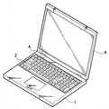
Translated fromKorean도 1은 본 발명에 따른 디스플레이장치가 적용된 컴퓨터의 사시도,1 is a perspective view of a computer to which the display device according to the present invention is applied;
도 2는 도 1의 "A"영역의 부분확대 단면도,FIG. 2 is a partially enlarged cross-sectional view of region “A” of FIG. 1;
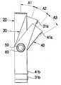
도 3은 본 발명에 따른 힌지장치의 분해사시도,3 is an exploded perspective view of a hinge device according to the present invention;
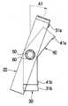
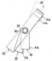
도 4 내지 도 7은 본 발명에 따른 힌지장치의 작동상태도이다.4 to 7 is an operating state diagram of the hinge device according to the present invention.
* 도면의 주요 부분에 대한 부호의 설명* Explanation of symbols for the main parts of the drawings
1 : 본체 4 : 모니터 1: body 4: monitor
10 : 고정브래킷 20 : 회동브래킷10: fixed bracket 20: rotating bracket
30 : 제1조절브래킷 40 : 제2조절브래킷30: first adjustment bracket 40: second adjustment bracket
50 : 힌지축 70 : 마찰부재50: hinge shaft 70: friction member
본 발명은 디스플레이장치에 관한 것으로써, 보다 상세하게는, 본체와의 결합구조가 개선된 디스플레이장치에 관한 것이다.The present invention relates to a display device, and more particularly, to a display device having an improved coupling structure with a main body.
디스플레이장치란 CRT모니터와 LCD모니터를 포함하는 화상 표시장치로서, TV나 컴퓨터에 사용되는 모니터와 그 주변 기기를 통틀어 일컫는다. 여기서는 종래의 디스플레이장치의 예로서 노트북 컴퓨터에 사용되는 디스플레이장치에 대해 설명하기로 한다.A display device is an image display device including a CRT monitor and an LCD monitor, and refers to a monitor used in a TV or a computer and its peripheral devices. Herein, a display device used in a notebook computer as an example of a conventional display device will be described.
삭제delete
삭제delete
삭제delete
컴퓨터는 중앙처리장치(CPU)가 장착되어 있는 메인보드(Main Board), 램(Ram) 및 디스크드라이버, 그래픽카드 등 각종 카드가 마련되어 있는 본체와, 본체에 전기적으로 연결되어 외부로 화상을 전달하는 모니터와, 본체에 정보를 입력하는 키보드 및 마우스 등을 포함하는 입력장치를 갖는다.The computer is equipped with a main board equipped with a CPU, a RAM, a disk driver, a graphics card, and a main body equipped with various cards, and is electrically connected to the main body to transfer images to the outside. It has a monitor and an input device including a keyboard and a mouse for inputting information into the main body.
본체와 모니터 사이에는 본체에 대해 모니터를 회동가능하게 지지하는 힌지장치가 마련되어 있다. 힌지장치는 모니터가 본체에 대해 상하방향(틸팅(Tilting)이라 함)으로 회동할 수 있도록 한다.A hinge device is provided between the main body and the monitor to rotatably support the monitor with respect to the main body. The hinge device allows the monitor to rotate up and down (called tilting) with respect to the main body.
그런데, 종래의 디스플레이장치에서는, 모니터의 회전각도 범위 내에서 힌지장치가 갖는 토오크가 일정하므로, 본체에 대해 모니터의 회전각도를 임의로 증가시키기가 용이하지 않다는 단점이 있다.However, in the conventional display device, since the torque of the hinge device is constant within the rotation angle range of the monitor, there is a disadvantage that it is not easy to arbitrarily increase the rotation angle of the monitor relative to the main body.
예를 들어, 본체에 대한 모니터의 회동각도 범위가 약 45도가 되도록 힌지장치의 토오크를 조절해놓을 경우, 별 무리 없이 모니터가 45도 각도까지 회동할 수 있다. 그러나, 45도 이상으로 모니터를 회동시키고자 할 경우에는, 모니터의 회동에 많은 힘이 필요할 뿐만 아니라 회동 자체가 쉽지 않다.For example, if the torque of the hinge device is adjusted so that the rotation angle range of the monitor relative to the main body is about 45 degrees, the monitor can be rotated up to 45 degrees without difficulty. However, when the monitor is to be rotated by 45 degrees or more, not only a lot of power is required to rotate the monitor but also the rotation itself is not easy.
반대로, 힌지장치의 토오크를 약하게 조절하며, 모니터의 회동을 수월하게 할 수는 있으나, 일정 각도에서 모니터의 각도를 유지하기가 어렵다는 문제점이 있다.On the contrary, the torque of the hinge device is weakly adjusted and the rotation of the monitor can be facilitated, but it is difficult to maintain the angle of the monitor at a certain angle.
따라서, 본 발명의 목적은, 모니터의 회동각도에 따라 토오크를 가변적으로 조절할 수 있도록 한 디스플레이장치를 제공하는 것이다.Accordingly, it is an object of the present invention to provide a display device capable of variably adjusting torque according to the rotation angle of a monitor.
상기 목적은, 본 발명에 따라, 디스플레이장치에 있어서, 화상을 표시하는 모니터와; 상기 모니터를 본체에 대해 회동가능하게 결합시키며, 상기 모니터의 회동각도에 따른 토오크를 가변할 수 있도록 한 힌지장치를 포함하는 것을 특징으로 하는 디스플레이장치에 의해 달성된다.According to the present invention, there is provided a display apparatus comprising: a monitor for displaying an image; It is achieved by a display device comprising a hinge device for rotatably coupling the monitor with respect to the main body and for varying the torque according to the rotation angle of the monitor.
여기서, 상기 힌지장치는, 상기 본체에 결합되는 고정브래킷과; 상기 모니터에 결합되어 상기 고정브래킷에 대해 상대 회동가능한 회동브래킷과; 상기 회동브래킷에 인접하게 배치되어 상기 회동브래킷의 회동각도를 제한하는 적어도 하나의 조절브래킷과; 상기 고정브래킷, 상기 회동브래킷 및 상기 조절브래킷의 판면을 관통하여 배치되는 힌지축을 포함한다.Here, the hinge device, the fixing bracket is coupled to the main body; A rotation bracket coupled to the monitor and rotatable relative to the fixed bracket; At least one adjustment bracket disposed adjacent to the rotation bracket to limit the rotation angle of the rotation bracket; It includes a hinge shaft disposed through the plate surface of the fixed bracket, the rotation bracket and the adjustment bracket.
상기 조절브래킷은, 상기 고정브래킷을 향한 상기 회동브래킷의 전방에 배치되는 제1조절브래킷과, 상기 회동브래킷의 후방에 배치되는 제2조절브래킷을 포함하며, 상기 각 제1 및 제2조절브래킷에는 상기 회동브래킷의 측면에 접촉하여 상기 회동브래킷의 회동각도를 제한하는 적어도 하나의 스토퍼가 형성되어 있다.The adjustment bracket includes a first adjustment bracket disposed in front of the rotation bracket toward the fixed bracket, and a second adjustment bracket disposed behind the rotation bracket, wherein each of the first and second adjustment brackets At least one stopper is formed in contact with the side surface of the rotation bracket to limit the rotation angle of the rotation bracket.
상기 스토퍼는 상기 제1 및 제2조절브래킷의 양단에 각각 배치된다. 상기 스토퍼는 상기 회동브래킷을 향해 돌출되어 있고, 상기 제1 및 제2조절브래킷의 길이는 상기 회동브래킷의 길이보다 짧게 형성된다. 상기 제1 및 제2조절브래킷은 상기 회동브래킷에 대해 소정 각도 절곡된 것이 유리하다.The stopper is disposed at both ends of the first and second adjustment brackets, respectively. The stopper protrudes toward the pivot bracket, and the length of the first and second adjustment brackets is shorter than that of the pivot bracket. The first and second adjustment brackets are advantageously bent at an angle to the pivot bracket.
삭제delete
상기 회동브래킷과 상기 제1 및 제2조절브래킷 사이에는 상기 힌지축에 끼워지는 마찰부재가 개재된다. 상기 마찰부재는 상기 제1 및 제2조절브래킷에 대한 상기 회동브래킷의 회전시 탄성을 부여하고 마찰을 흡수하는 점탄성의 고무재질로 이루어진다.A friction member fitted to the hinge shaft is interposed between the pivot bracket and the first and second adjustment brackets. The friction member is made of a viscoelastic rubber material that provides elasticity and absorbs friction when the rotation bracket rotates with respect to the first and second adjustment brackets.
상기 힌지축에는 상기 힌지축에 대해 상기 각 브래킷의 이탈을 방지하는 이탈방지너트가 설치된다.The hinge shaft is provided with a release preventing nut for preventing the separation of the bracket with respect to the hinge shaft.
이하에서는 첨부도면을 참조하여 본 발명에 대해 상세히 설명한다.Hereinafter, the present invention will be described in detail with reference to the accompanying drawings.
이하, 본 발명은 노트북 컴퓨터를 일 적용예로 하여 설명한다. 본 명세서에서 "본체"란 컴퓨터처럼 본 발명의 디스플레이장치와 결합되는 요소를 지칭한다. 그러나, TV와 같이 본체와 디스플레이장치가 일체로 구성되는 경우에도 본 발명의 사상이 적용될 수 있음은 물론이다.
본 발명의 디스플레이장치가 적용된 컴퓨터는, 도 1에 도시된 바와 같이, 중앙처리장치(CPU)가 장착되어 있는 메인보드(Main Board), 램(Ram) 및 디스크드라이버, 그래픽카드 등 각종 카드가 설치되어 있는 본체(1)와, 본체(1)에 결합되어 화상을 표시하는 모니터(4)를 갖는다. 본체(1)에는 소정의 정보를 입력하는 입력부(2)가 설치되어 있다. 모니터(4)는 후술하는 힌지장치(100)와 함께 본 발명에 따른 디스플레이장치를 구성한다.Hereinafter, the present invention will be described using a notebook computer as an application example. As used herein, the term "body" refers to an element that is combined with a display device of the present invention, such as a computer. However, it is a matter of course that the idea of the present invention can be applied even when the main body and the display device are integrally formed, such as a TV.
In the computer to which the display device of the present invention is applied, as shown in FIG. 1, various cards such as a main board, a RAM, a disk driver, and a graphics card, on which a CPU is installed, are installed. And a
본체(1)와 모니터(4) 사이에는 도 2에 도시된 바와 같이, 모니터(4)를 본체(1)에 대해 틸팅시키며, 모니터(4)의 회동각도에 따른 토오크를 가변조절할 수 있도록 한 힌지장치(100)가 마련되어 있다.As shown in FIG. 2, the hinge between the main body 1 and the
힌지장치(100)는, 본체(1)에 결합되는 고정브래킷(10)과, 모니터(4)에 결합되어 고정브래킷(10)에 대해 상대 회동가능한 회동브래킷(20)과, 회동브래킷(20)의 전방 및 후방에 배치되어 회동브래킷(20)의 회동각도를 제한하는 제1 및 제2 조절브래킷(30,40)과, 고정브래킷(10), 회동브래킷(20) 및 제1 및 제2조절브래킷(30,40)의 판면을 관통하여 배치되는 힌지축(50)을 포함한다.The
도 3에 도시된 바와 같이, 고정브래킷(10)은, 본체(1)에 결합되도록 판면을 관통하는 복수의 나사관통공(12)이 형성된 고정부(11)와, 고정부(11)에 대해 대략 수직으로 절곡되며 힌지축(50)을 수용하도록 제1축공(15)이 관통형성된 절곡부(14)를 갖는다. 회동브래킷(20)도 모니터(4)에 결합되도록 복수의 나사관통공(23)이 형성된 결합부(22)와, 결합부(22)에 대해 대략 수직으로 절곡된 연장부(24)를 갖는다.As shown in FIG. 3, the
회동브래킷(20)의 전방 및 후방에는 회동브래킷(20)의 회동각도를 제한하는 제1 및 제2조절브래킷(30,40)이 각각 설치되어 있다. 이 때, 제1 및 제2조절브래킷(30,40)은 회동브래킷(20)과 간섭되지 않도록 회동브래킷(20)의 길이보다 작은 길이를 갖도록 형성되며, 도 4에 도시된 바와 같이 회동브래킷(20)에 대해 각각 소정 각도(A1,A2)를 갖도록 절곡 형성된다.First and
제1 및 제2조절브래킷(30,40)의 판면에는 힌지축(50)이 삽입될 수 있도록 제3축공(33) 및 제4축공(44)이 형성되어 있으며, 제1 및 제2조절브래킷(30,40)의 양단에는 회동브래킷(20)의 측면에 접촉하여 회동브래컷(20)의 회동각을 제한하는 한 쌍의 스토퍼(31a,31b,41a,41b)가 각각 형성되어 있다. 각 스토퍼(31a,31b,41a,41b)는, 제1 및 제2조절브래킷(30,40)의 양단으로부터 회동브래킷(20)을 향해 각각 돌출되어 있다.A
회동브래킷(20)과 제1 및 제2조절브래킷(30,40) 사이에는 힌지축(50)에 끼워지는 마찰부재(70)가 각각 개재되어 있다. 마찰부재(70)는 점탄성의 고무재질로 형성되어 제1 및 제2조절브래킷(30,40)에 대한 회동브래킷(20)의 회전시 탄성을 부여하고 마찰을 흡수한다.A
힌지축(50)은 고정브래킷(10)의 제1축공(15)에 삽입되는 제1축부(52)와, 제1 및 제2조절브래킷(30,40)의 제3 및 제4축공(33,44)과 회동브래킷(20)의 제2축공(22)에 삽입되는 제2축부(53)를 포함한다. 제2축부(53)의 단부에는 나사부(53a)가 형성되어 있으며, 제1축부(52)와 제2축부(53) 사이에는 플랜지부(55)가 형성되어 있다. 그리고, 제2축부(53)의 나사부(53a)에는 힌지축(50)에 대해 각 브래킷(20,30,40)의 이탈을 방지하는 이탈방지너트(60)가 끼워져 있으며, 플랜지부(55)와 제1조절브래킷(30) 사이 및 제2조절브래킷(40)과 너트(60) 사이에는 와셔(80,90)가 개재되어 있다. 여기서, 와셔(80,90)는 스프링와셔(80) 및 평와셔(90)로 구분할 수 있는데, 그 위치,종류 및 개수는 필요에 따라 변경될 수도 있다.The
상기의 구성을 갖는 디스플레이장치를 본체(1)에 조립하는 과정을 설명하면 다음과 같다.Referring to the process of assembling the display device having the above configuration to the main body 1 as follows.
먼저, 고정브래킷(10)의 고정부(11)의 나사관통공(12)으로 나사를 삽입하여 고정브래킷(10)을 본체(1)에 결합한 다음, 힌지축(50)의 제1축부(52)를 제1축공(15)으로 삽입한다. 그런 다음, 한 쌍의 스프링와셔(80)를 힌지축(50)의 제2축부(53)에 삽입한 후, 제1조절브래킷(30)의 제3축공(33)을 제2축부(53)로 삽입하여 제1조절브래킷(30)을 힌지축(50)에 장착한다.First, the screw is inserted into the screw through
다음, 한 쌍의 마찰부재(70)를 사이에 두고 제2축부(53)에 회동브래킷(20) 및 제2조절브래킷(40)을 차례로 결합한 후, 스프링와셔(80)와 평와셔(90)를 삽입하고, 최종적으로 이탈방지너트(60)를 구동축부(53)의 나사부(53a)에 결합한다. 그런 연후에, 회동브래킷(20)의 결합부(22)에 모니터(4)를 결합함으로써, 본체(1)에 본 발명에 따른 디스플레이장치를 조립하는 과정은 완료된다. 모니터(4)와 본체(1) 사이에는 한 쌍의 힌지장치(100)가 개재되는 것이 바람직하다.Next, after coupling the
이처럼, 본체(1)에 디스플레이장치의 설치가 완료되면, 회동브래킷(20)과 제1 및 제2조절브래킷(30,40)은 도 4에 도시된 바와 같은 상태로 배치된다. 이 상태에서 회동브래킷(20)을 각도(A1,A2,A3)만큼 단계적으로 틸팅시킬 때 발생하는 토오크 변화를 설명하면 다음과 같다.As such, when the installation of the display device on the main body 1 is completed, the
먼저, 도 5에 도시된 바와 같이, 회동브래킷(20)을 각도(A1)만큼 틸팅시키면, 각도(A1)까지는 토오크의 변화 없이 틸팅되다가 회동브래킷(20)의 측면이 제1조절브래킷(30)의 상측 스토퍼(31a)에 걸리게 된다. 이 때, 힘을 더 가하지 않게 되면, 최초 각도(A1)만큼 틸팅된 회동브래킷(20)은 제1조절브래킷(30)의 상측 스토퍼(31a)로 인해 더 이상 틸팅되지 않는다.First, as shown in FIG. 5, when the tilting
모니터(4)의 틸팅각도를 더 크게 유지하기 위해, 회동브래킷(20)을 각도(A2)만큼 더 틸팅시킬 때는, 회동브래킷(20)은 제1조절브래킷(30)의 상측 스토퍼(31a)에 걸림유지되어 있으므로 제1조절브래킷(30)과 함께 틸팅된다. 이 때는 회동브래킷(20)을 각도(A1)만큼 틸팅할 때보다 더 많은 힘이 필요하다.In order to keep the tilting angle of the
각도(A2)만큼 틸팅된 후에는, 도 6에 도시된 바와 같이, 회동브래킷(20)의 측면이 제2조절브래킷(40)의 상측 스토퍼(41a)에 걸리게 된다. 이 때, 힘을 더 가하지 않게 되면, 제2조절브래킷(40)의 상측 스토퍼(41a)로 인해 회동브래킷(20)과 제1조절브래킷(30)은 더 이상 틸팅되지 않는다. 이 상태에서는, 도 6에 도시된 바와 같이 회동브래킷(20)과 제1 및 제2조절브래킷(30,40)의 상측 영역이 상호 포개지는 형태를 띤다.After tilting by the angle A2, as shown in FIG. 6, the side surface of the
모니터(4)의 틸팅 각도를 더 크게 유지시키기 위해, 도 7에 도시된 바와 같이, 회동브래킷(20)을 각도(A3)만큼 더 틸팅시킬 때는 회동브래킷(20)을 각도(A2)로 틸팅시킬 때보다 더 많은 힘이 필요하게 된다.In order to keep the tilting angle of the
마찬가지로, 전술한 회동방향과 반대 방향으로 회동브래킷(20)을 틸팅시킬 때는, 회동브래킷(20)의 측면은 먼저 제1조절브래킷(30)의 하측 스토퍼(31b)에 걸려 제1조절브래킷(30)과 함께 틸팅된 후, 다시 제2조절브래킷(40)의 하측 스토퍼(41b)에 걸려 제2조절브래킷(40)과 함께 틸팅될 수 있다.Similarly, when tilting the
따라서, 모니터(4)의 틸팅각도에 따른 토오크를 가변적으로 조절하여 모니터(4)의 틸팅각도를 다양하게 유지시킬 수 있고 모니터(4)의 시청범위를 용이하게 확장시킬 수 있다.Accordingly, by adjusting the torque according to the tilting angle of the
이상 설명한 바와 같이, 본 발명에 따르면, 모니터의 회동 각도에 따라 토오크를 가변적으로 조절할 수 있도록 한 디스플레이장치가 제공된다.As described above, according to the present invention, there is provided a display apparatus which can variably adjust the torque according to the rotation angle of the monitor.
Claims (10)
Translated fromKoreanPriority Applications (2)
| Application Number | Priority Date | Filing Date | Title |
|---|---|---|---|
| KR1020010008224AKR100703160B1 (en) | 2001-02-19 | 2001-02-19 | Display device |
| US09/902,156US6453509B1 (en) | 2001-02-19 | 2001-07-11 | Hinge arrangement for a display apparatus |
Applications Claiming Priority (1)
| Application Number | Priority Date | Filing Date | Title |
|---|---|---|---|
| KR1020010008224AKR100703160B1 (en) | 2001-02-19 | 2001-02-19 | Display device |
Publications (2)
| Publication Number | Publication Date |
|---|---|
| KR20020067946A KR20020067946A (en) | 2002-08-24 |
| KR100703160B1true KR100703160B1 (en) | 2007-04-05 |
Family
ID=19705932
Family Applications (1)
| Application Number | Title | Priority Date | Filing Date |
|---|---|---|---|
| KR1020010008224AExpired - Fee RelatedKR100703160B1 (en) | 2001-02-19 | 2001-02-19 | Display device |
Country Status (2)
| Country | Link |
|---|---|
| US (1) | US6453509B1 (en) |
| KR (1) | KR100703160B1 (en) |
Families Citing this family (44)
| Publication number | Priority date | Publication date | Assignee | Title |
|---|---|---|---|---|
| DE10013726C2 (en)* | 2000-03-21 | 2003-01-16 | Edscha Ag | Klappenscharnier |
| US7047599B2 (en)* | 2000-12-11 | 2006-05-23 | Sugatsune Kogyo Co., Ltd. | Hinge assembly |
| TW517202B (en)* | 2001-01-19 | 2003-01-11 | Wistron Corp | Pivotal connection device of keyboard having pup-up keys |
| KR100414670B1 (en)* | 2001-11-28 | 2004-01-13 | 삼성전자주식회사 | Hinge device |
| KR100443869B1 (en)* | 2001-12-24 | 2004-08-09 | 엘지전자 주식회사 | Hinge assembly for flat panel display appliance |
| MXPA04003745A (en)* | 2001-12-24 | 2004-07-23 | Lg Electronics Inc | Hinge assembly for flat panel display appliance. |
| CN1279419C (en)* | 2001-12-24 | 2006-10-11 | Lg电子株式会社 | Hinge assembly for flat panel display appliance |
| WO2003062970A1 (en)* | 2001-12-24 | 2003-07-31 | Lg Electronics Inc. | Hinge assembly for flat panel display appliance |
| TW553576U (en)* | 2002-04-18 | 2003-09-11 | Quanta Comp Inc | Flat panel display and the folded base thereof |
| US6905101B1 (en) | 2002-06-11 | 2005-06-14 | Chief Manufacturing Inc. | Adjustable, self-balancing flat panel display mounting system |
| US6581893B1 (en)* | 2002-09-05 | 2003-06-24 | Shin Zu Shing Co., Ltd. | Stand for an LCD monitor |
| US6813813B2 (en)* | 2003-01-06 | 2004-11-09 | Shin Zu Shing Co., Ltd. | Collapsible hinge bracket for a laptop computer |
| US7152836B2 (en) | 2003-01-09 | 2006-12-26 | Csav, Inc. | Adjustable tilt mount |
| US20050039301A1 (en)* | 2003-08-22 | 2005-02-24 | Lu Sheng-Nan | Hinge assembly |
| KR20030086551A (en)* | 2003-10-22 | 2003-11-10 | 금호석유화학 주식회사 | Nucleic acid molecules encoding annexins from plants |
| TWM247160U (en)* | 2003-12-03 | 2004-10-21 | Ching Feng Home Fashions Co | Shower screen shield |
| KR100541321B1 (en)* | 2004-02-19 | 2006-01-10 | 홍경희 | Torque adjustable hinge |
| USD518484S1 (en)* | 2004-08-18 | 2006-04-04 | Fujitsu Limited | Personal computer |
| CN1753606A (en)* | 2004-09-24 | 2006-03-29 | 深圳富泰宏精密工业有限公司 | Hinge and mobile telephone using said hinge |
| CN100445584C (en)* | 2005-08-26 | 2008-12-24 | 鸿富锦精密工业(深圳)有限公司 | hinge device |
| US7641163B2 (en)* | 2005-10-21 | 2010-01-05 | Peerless Industries, Inc. | Tilt mounting system |
| US20070169316A1 (en)* | 2006-01-20 | 2007-07-26 | Shin Zu Shing Co., Ltd. | Hinge with a positioning and limiting assembly |
| JP2007193245A (en)* | 2006-01-23 | 2007-08-02 | Funai Electric Co Ltd | Display screen supporting mechanism |
| US20080073471A1 (en)* | 2006-09-25 | 2008-03-27 | Beger Lawrence J | Two in One Video Monitor Mount |
| CN101720482B (en) | 2007-01-03 | 2014-02-26 | 迈尔史东视讯科技股份有限公司 | Device mount with selectively positionable tilt axis |
| AU2008205387A1 (en) | 2007-01-05 | 2008-07-17 | Milestone Av Technologies Llc | Wall-avoiding self-balancing mount for tilt positioning of a flat panel electronic display |
| US7866622B2 (en) | 2007-01-05 | 2011-01-11 | Milestone Av Technologies Llc | In-wall mount |
| US7891622B1 (en) | 2007-02-02 | 2011-02-22 | Peerless Industries, Inc. | Adjustable tilt mounting system |
| TWM322709U (en)* | 2007-05-08 | 2007-11-21 | Jarllytec Co Ltd | Dual open/close pivot structure |
| USD595702S1 (en) | 2008-01-04 | 2009-07-07 | Milestone Av Technologies Llc | Tilt adjustable display interface bracket |
| US7823847B2 (en) | 2008-01-04 | 2010-11-02 | Milestone Av Technologies Llc | Display mount with post-installation adjustment features |
| US8958200B2 (en) | 2008-01-04 | 2015-02-17 | Milestone Av Technologies Llc | Display mount with post-installation adjustment features |
| US20110013350A1 (en)* | 2008-03-04 | 2011-01-20 | Tracy Mark S | Friction Mechanisms For Computing Devices |
| US20090235509A1 (en)* | 2008-03-20 | 2009-09-24 | Beger Lawrence J | Tool-Less Television Stand |
| EP2329645A4 (en) | 2008-09-02 | 2011-11-30 | Milestone Av Technologies Llc | Low profile mount for flat panel electronic display |
| US8891249B2 (en) | 2009-01-07 | 2014-11-18 | Milestone Av Technologies Llc | Display mount with adjustable position tilt axis |
| USD620943S1 (en) | 2009-01-07 | 2010-08-03 | Milestone Av Technologies Llc | Single arm display mount |
| USD627787S1 (en) | 2009-01-07 | 2010-11-23 | Milestone Av Technologies Llc | Display mount with single articulating arm |
| US8015667B2 (en)* | 2009-02-16 | 2011-09-13 | Hamilton Sundstrand Corporation | Controlled rigging |
| CN201513461U (en)* | 2009-08-03 | 2010-06-23 | 康准电子科技(昆山)有限公司 | hub |
| JP5228003B2 (en)* | 2010-07-20 | 2013-07-03 | 森六テクノロジー株式会社 | Hinge structure of vehicular storage device |
| US20120050960A1 (en)* | 2010-09-01 | 2012-03-01 | Hsiang-Chi Chien | Simplified hinge and a portable electronic device with the same |
| US10356919B2 (en)* | 2017-09-15 | 2019-07-16 | Wuhan China Star Optoelectronics Semiconductor Display Technology Co., Ltd. | Foldable module and flexible display device having the same |
| CN107393424B (en)* | 2017-09-15 | 2019-05-03 | 武汉华星光电半导体显示技术有限公司 | A kind of collapsible component and flexible display apparatus |
Citations (4)
| Publication number | Priority date | Publication date | Assignee | Title |
|---|---|---|---|---|
| JPH0916094A (en)* | 1995-06-29 | 1997-01-17 | Matsushita Electric Ind Co Ltd | Electric switchgear |
| JPH11214859A (en)* | 1998-01-27 | 1999-08-06 | Kato Electrical Mach Co Ltd | Tilt hinge |
| KR19990075422A (en)* | 1998-03-20 | 1999-10-15 | 윤종용 | Flat panel display device having hinge portion with variable tilt torque |
| KR20000005174U (en)* | 1998-08-24 | 2000-03-25 | 한흥섭 | Hinge structure for monitor |
Family Cites Families (15)
| Publication number | Priority date | Publication date | Assignee | Title |
|---|---|---|---|---|
| US3979791A (en)* | 1974-05-22 | 1976-09-14 | Alcan Booth Industries Limited | Window hinges |
| JPH04254683A (en) | 1991-02-05 | 1992-09-09 | Matsushita Electric Ind Co Ltd | Rotary hinge |
| US5208944A (en)* | 1992-06-16 | 1993-05-11 | Lu Sheng N | Hinge device for casings |
| JP3283064B2 (en) | 1992-06-30 | 2002-05-20 | 加藤電機株式会社 | Tilt hinge |
| KR940011764A (en) | 1992-11-27 | 1994-06-22 | 정용문 | High Reliability Hinge |
| US5784759A (en)* | 1993-11-02 | 1998-07-28 | King; David Russell | Hinge construction |
| US5566048A (en)* | 1994-06-02 | 1996-10-15 | Hewlett-Packard Company | Hinge assembly for a device having a display |
| JPH09196048A (en) | 1996-01-18 | 1997-07-29 | Kato Electrical Mach Co Ltd | Tilt hinge |
| JPH1026128A (en) | 1996-07-10 | 1998-01-27 | Kato Electrical Mach Co Ltd | Tilt hinge |
| JP3937523B2 (en)* | 1997-09-25 | 2007-06-27 | ソニー株式会社 | Hinge for electronic device and electronic device having hinge |
| US5915441A (en)* | 1997-10-03 | 1999-06-29 | Southco, Inc. | Dual pivot hinge assembly |
| US5901415A (en)* | 1997-10-03 | 1999-05-11 | Southco, Inc. | Dual pivot hinge assembly |
| JP3798899B2 (en) | 1998-01-27 | 2006-07-19 | 加藤電機株式会社 | Tilt hinge |
| KR19990079371A (en) | 1998-04-04 | 1999-11-05 | 윤종용 | Flat panel display device having a hinge portion with variable tilt torque |
| US6286187B1 (en)* | 2000-03-03 | 2001-09-11 | Jarlly Technology Co., Ltd. | Rotary hinge shaft assembly |
- 2001
- 2001-02-19KRKR1020010008224Apatent/KR100703160B1/ennot_activeExpired - Fee Related
- 2001-07-11USUS09/902,156patent/US6453509B1/ennot_activeExpired - Lifetime
Patent Citations (4)
| Publication number | Priority date | Publication date | Assignee | Title |
|---|---|---|---|---|
| JPH0916094A (en)* | 1995-06-29 | 1997-01-17 | Matsushita Electric Ind Co Ltd | Electric switchgear |
| JPH11214859A (en)* | 1998-01-27 | 1999-08-06 | Kato Electrical Mach Co Ltd | Tilt hinge |
| KR19990075422A (en)* | 1998-03-20 | 1999-10-15 | 윤종용 | Flat panel display device having hinge portion with variable tilt torque |
| KR20000005174U (en)* | 1998-08-24 | 2000-03-25 | 한흥섭 | Hinge structure for monitor |
Also Published As
| Publication number | Publication date |
|---|---|
| US6453509B1 (en) | 2002-09-24 |
| US20020112318A1 (en) | 2002-08-22 |
| KR20020067946A (en) | 2002-08-24 |
Similar Documents
| Publication | Publication Date | Title |
|---|---|---|
| KR100703160B1 (en) | Display device | |
| US6912120B2 (en) | Tilting and shielding apparatus of monitor | |
| US7334765B2 (en) | Display apparatus | |
| KR101599301B1 (en) | Electronic apparatus | |
| KR100394525B1 (en) | tilt hinge | |
| US7986517B2 (en) | Notebook computer | |
| US9021659B2 (en) | Hinge structure | |
| US7530541B2 (en) | Flat panel display with pivot mechanism | |
| KR19990024492U (en) | Flat panel display device with hinged device for tilt operation | |
| US20020015282A1 (en) | Computer system having a monitor movably coupled to a main body | |
| US20030042385A1 (en) | Liquid crystal display with a ball-and-socket mounting joint | |
| CN1882234A (en) | Swiveling apparatus for a monitor apparatus | |
| CN102859999B (en) | Display device | |
| EP1388629A1 (en) | Automatic homing rotary hinge | |
| US9846456B2 (en) | Portable electronic device | |
| KR100566476B1 (en) | apparatus for an inclination motion | |
| US20090268106A1 (en) | Display Screen Support Mechanism and Television Set | |
| KR200182807Y1 (en) | Swivel stand apparatus for lcd monitor | |
| KR19990040014U (en) | monitor | |
| JP3842797B2 (en) | Display support device | |
| US20110128691A1 (en) | Unitary computing device having orientation adjusting mechanism | |
| KR100645911B1 (en) | Hinge Apparatus for Notebook Computer | |
| CN2567930Y (en) | Pivot device with adjustable limit point resistance | |
| JPH0447737Y2 (en) | ||
| KR200359038Y1 (en) | torque hinge unit |
Legal Events
| Date | Code | Title | Description |
|---|---|---|---|
| PA0109 | Patent application | St.27 status event code:A-0-1-A10-A12-nap-PA0109 | |
| PN2301 | Change of applicant | St.27 status event code:A-3-3-R10-R13-asn-PN2301 St.27 status event code:A-3-3-R10-R11-asn-PN2301 | |
| P11-X000 | Amendment of application requested | St.27 status event code:A-2-2-P10-P11-nap-X000 | |
| P13-X000 | Application amended | St.27 status event code:A-2-2-P10-P13-nap-X000 | |
| PG1501 | Laying open of application | St.27 status event code:A-1-1-Q10-Q12-nap-PG1501 | |
| R18-X000 | Changes to party contact information recorded | St.27 status event code:A-3-3-R10-R18-oth-X000 | |
| R18-X000 | Changes to party contact information recorded | St.27 status event code:A-3-3-R10-R18-oth-X000 | |
| R18-X000 | Changes to party contact information recorded | St.27 status event code:A-3-3-R10-R18-oth-X000 | |
| PN2301 | Change of applicant | St.27 status event code:A-3-3-R10-R13-asn-PN2301 St.27 status event code:A-3-3-R10-R11-asn-PN2301 | |
| PN2301 | Change of applicant | St.27 status event code:A-3-3-R10-R13-asn-PN2301 St.27 status event code:A-3-3-R10-R11-asn-PN2301 | |
| A201 | Request for examination | ||
| PA0201 | Request for examination | St.27 status event code:A-1-2-D10-D11-exm-PA0201 | |
| D13-X000 | Search requested | St.27 status event code:A-1-2-D10-D13-srh-X000 | |
| D14-X000 | Search report completed | St.27 status event code:A-1-2-D10-D14-srh-X000 | |
| E902 | Notification of reason for refusal | ||
| PE0902 | Notice of grounds for rejection | St.27 status event code:A-1-2-D10-D21-exm-PE0902 | |
| P11-X000 | Amendment of application requested | St.27 status event code:A-2-2-P10-P11-nap-X000 | |
| P13-X000 | Application amended | St.27 status event code:A-2-2-P10-P13-nap-X000 | |
| E701 | Decision to grant or registration of patent right | ||
| PE0701 | Decision of registration | St.27 status event code:A-1-2-D10-D22-exm-PE0701 | |
| GRNT | Written decision to grant | ||
| PR0701 | Registration of establishment | St.27 status event code:A-2-4-F10-F11-exm-PR0701 | |
| PR1002 | Payment of registration fee | St.27 status event code:A-2-2-U10-U11-oth-PR1002 Fee payment year number:1 | |
| PG1601 | Publication of registration | St.27 status event code:A-4-4-Q10-Q13-nap-PG1601 | |
| PR1001 | Payment of annual fee | St.27 status event code:A-4-4-U10-U11-oth-PR1001 Fee payment year number:4 | |
| PR1001 | Payment of annual fee | St.27 status event code:A-4-4-U10-U11-oth-PR1001 Fee payment year number:5 | |
| PR1001 | Payment of annual fee | St.27 status event code:A-4-4-U10-U11-oth-PR1001 Fee payment year number:6 | |
| R18-X000 | Changes to party contact information recorded | St.27 status event code:A-5-5-R10-R18-oth-X000 | |
| FPAY | Annual fee payment | Payment date:20130227 Year of fee payment:7 | |
| PR1001 | Payment of annual fee | St.27 status event code:A-4-4-U10-U11-oth-PR1001 Fee payment year number:7 | |
| FPAY | Annual fee payment | Payment date:20140227 Year of fee payment:8 | |
| PR1001 | Payment of annual fee | St.27 status event code:A-4-4-U10-U11-oth-PR1001 Fee payment year number:8 | |
| FPAY | Annual fee payment | Payment date:20150226 Year of fee payment:9 | |
| PR1001 | Payment of annual fee | St.27 status event code:A-4-4-U10-U11-oth-PR1001 Fee payment year number:9 | |
| FPAY | Annual fee payment | Payment date:20160226 Year of fee payment:10 | |
| PR1001 | Payment of annual fee | St.27 status event code:A-4-4-U10-U11-oth-PR1001 Fee payment year number:10 | |
| LAPS | Lapse due to unpaid annual fee | ||
| PC1903 | Unpaid annual fee | St.27 status event code:A-4-4-U10-U13-oth-PC1903 Not in force date:20170329 Payment event data comment text:Termination Category : DEFAULT_OF_REGISTRATION_FEE | |
| PC1903 | Unpaid annual fee | St.27 status event code:N-4-6-H10-H13-oth-PC1903 Ip right cessation event data comment text:Termination Category : DEFAULT_OF_REGISTRATION_FEE Not in force date:20170329 |