KR100701776B1 - Moving part structure of the air circuit breaker - Google Patents
Moving part structure of the air circuit breakerDownload PDFInfo
- Publication number
- KR100701776B1 KR100701776B1KR1020060008852AKR20060008852AKR100701776B1KR 100701776 B1KR100701776 B1KR 100701776B1KR 1020060008852 AKR1020060008852 AKR 1020060008852AKR 20060008852 AKR20060008852 AKR 20060008852AKR 100701776 B1KR100701776 B1KR 100701776B1
- Authority
- KR
- South Korea
- Prior art keywords
- mover
- movable
- circuit breaker
- air circuit
- insulating cage
- Prior art date
- Legal status (The legal status is an assumption and is not a legal conclusion. Google has not performed a legal analysis and makes no representation as to the accuracy of the status listed.)
- Expired - Fee Related
Links
Images


Classifications
- Y—GENERAL TAGGING OF NEW TECHNOLOGICAL DEVELOPMENTS; GENERAL TAGGING OF CROSS-SECTIONAL TECHNOLOGIES SPANNING OVER SEVERAL SECTIONS OF THE IPC; TECHNICAL SUBJECTS COVERED BY FORMER USPC CROSS-REFERENCE ART COLLECTIONS [XRACs] AND DIGESTS
- Y02—TECHNOLOGIES OR APPLICATIONS FOR MITIGATION OR ADAPTATION AGAINST CLIMATE CHANGE
- Y02B—CLIMATE CHANGE MITIGATION TECHNOLOGIES RELATED TO BUILDINGS, e.g. HOUSING, HOUSE APPLIANCES OR RELATED END-USER APPLICATIONS
- Y02B20/00—Energy efficient lighting technologies, e.g. halogen lamps or gas discharge lamps
- Y02B20/72—Energy efficient lighting technologies, e.g. halogen lamps or gas discharge lamps in street lighting
Landscapes
- Breakers (AREA)
Abstract
Translated fromKoreanDescription
Translated fromKorean도 1은 종래의 기술에 따른 기중 차단기의 구성을 나타낸 단면도,1 is a cross-sectional view showing the configuration of an air circuit breaker according to the prior art,
도 2는 종래 기중 차단기의 차단동작완료 상태를 나타낸 단면도,2 is a cross-sectional view showing a state of completion of the breaking operation of the conventional air circuit breaker,
도 3A는 종래 가동부의 가동자를 나타낸 사시도,3A is a perspective view showing a movable part of a conventional movable part,
도 3B는 종래 가동부의 가동자 조립구조를 나타낸 분리사시도,3B is an exploded perspective view showing a mover assembly structure of a conventional movable unit;
도 4는 본 발명에 따른 기중 차단기의 구성을 나타낸 단면도,Figure 4 is a cross-sectional view showing the configuration of the air circuit breaker according to the present invention,
도 5는 본 발명에 따른 기중 차단기의 차단동작완료 상태를 나타낸 단면도,5 is a cross-sectional view showing a complete breaking operation state of the air circuit breaker according to the present invention;
도 6A는 본 발명에 따른 가동부의 가동자를 나타낸 사시도,6A is a perspective view showing a movable part of the movable part according to the present invention;
도 6B는 본 발명에 따른 가동부의 가동자 조립구조를 나타낸 분리사시도,6B is an exploded perspective view showing a movable assembly structure of the movable part according to the present invention;
* 도면의 주요 부분에 대한 부호의 설명 *Explanation of symbols on the main parts of the drawings
1 : 기중 차단기 10 : 상부 몰드케이스1: air circuit breaker 10: upper mold case
10a : 상단개구부 20 : 입력측 터미널10a: upper opening 20: input terminal
20a : 고정접점 30 : 부하측 터미널20a: fixed contact point 30: load side terminal
31 : 션트 40 : 하부 몰드케이스31: shunt 40: lower mold case
50 : 가동부 51 : 절연 케이지50: movable part 51: insulated cage
51a : 돌출부 52 : 가동자51a: protrusion 52: mover
52a : 가동접점 52b : 고정홀52a:
52c : 요철 52d : 스프링 고정홈52c:
53 : 접압스프링 54 : 링크53: contact spring 54: link
55 : 연결핀 56 : 회전핀55: connection pin 56: rotation pin
57 : 피봇핀 60 : 소호부57: pivot pin 60: lobe
61 : 배출구61 outlet
본 발명은 기중 차단기에 관한 것으로, 특히 통전시 통전부와 기구부간의 절연상태를 유지함과 아울러 추가 부품없이 차단기 가동자간의 거리를 유지시킬 수 있도록 한 기중 차단기의 가동부 구조에 관한 것이다.BACKGROUND OF THE
일반적으로 기중 차단기는 공장, 빌딩 등의 수배전 설비 중에서 주로 배전반에 설치되어 무부하 상태에서는 부하측에 전원을 공급 또는 차단하는 개폐장치의 역할을 하고, 부하 사용중에는 부하전로에 이상 현상이 발생하여 부하 전류를 초과하는 대전류가 흐를 경우, 부하측 기기를 보호하기 위하여 입력측으로부터 부하측으로 공급되는 전원을 공급 또는 차단하는 차단기 역할을 담당하게 된다.In general, the air circuit breaker is mainly installed in the switchgear among factories, buildings, etc., and serves as a switchgear that supplies or cuts power to the load side under no load, and an abnormal phenomenon occurs in the load circuit during load use. When a large current exceeding the current flows, it acts as a circuit breaker to supply or cut off the power supplied from the input side to the load side to protect the load side equipment.
즉, 상기 기중 차단기는 크게 차단기 내의 가동접점과 고정접점의 접촉이 이루어지도록 개폐시켜주는 기구부와, 단락사고시 발생하는 아크 및 고압의 가스를 신속하게 제거하는 소호부와, 입력측에서 과전류나 순시전류 및 단락전류 발생시 이를 감지하여 개폐기구부의 전원을 차단시켜주기 위한 트립동작신호를 유도하는 트립부로 구성된다.That is, the air circuit breaker has a mechanism part that opens and closes the contact between the movable contact and the fixed contact in the breaker, a arcing part for quickly removing arc and high pressure gas generated in a short circuit accident, and an overcurrent or instantaneous current and It consists of a trip part that detects this when a short circuit current occurs and induces a trip operation signal to cut off the power supply of the switch mechanism part.
따라서, 상기 기중 차단기는 전원과 부하 사이에서 이상전류 즉, 과전류나 순시전류 및 단락전류 발생시 이를 차단하여 부하 및 회로의 보호기능을 하게 된다.Therefore, the air circuit breaker cuts off an abnormal current, that is, an overcurrent or instantaneous current and a short-circuit current between the power supply and the load, thereby protecting the load and the circuit.
한편, 이상전류 발생시 인위적인 개폐와는 무관하게 차단기 내에서 이를 인지하여 자동으로 전류를 차단시켜 주게 되는데 이를 통상 트립이라 지칭한다.On the other hand, when an abnormal current occurs, regardless of artificial opening and closing in the circuit breaker to recognize the current automatically it is called a trip.
회로에서 순시전류 이상의 높은 단락전류 발생시 차단기의 트립부에서 이를 감지하여 트립신호를 기구부에 보내게 되어 트립동작이 이루어지는 것이 일반적이며, 상기 기구부와 통전부는 완전한 절연상태를 유지하여야 한다.When a high short circuit current of more than instantaneous current occurs in the circuit, the trip part of the circuit breaker detects this and sends a trip signal to the mechanical part, so that a trip operation is generally performed.
또한, 다수의 가동자로 이루어진 상기 기중 차단기의 특성상 각 가동자는 개별적인 운동이 가능하도록 되어 있고, 이에 따라 상기 가동자 사이에는 일정한 간격이 유지되어야만 하며, 간격 유지를 위해 상기 가동자 사이에 스페이서 역할을 하는 추가부품의 설치가 필요하게 된다.In addition, due to the characteristics of the air circuit breaker consisting of a plurality of movers, each mover is to be able to move individually, accordingly, a certain distance must be maintained between the movers, and acts as a spacer between the movers to maintain the gap It is necessary to install additional parts.
즉, 도 1은 정격전류 통전시 종래 기중 차단기의 구성을 도시한 것으로, 상기 기중 차단기(100)는 절연재료로 성형된 상부 몰드케이스(101)와 하부 몰드케이스(102)는 다수의 부품이 설치되는 공간을 형성한다.That is, Figure 1 shows the configuration of a conventional air circuit breaker when the rated current is energized, the
상기 상하부 몰드케이스(101,102)의 내부에 기구부(도시되지 않음)의 메커니즘으로부터 힘을 전달받는 가동부(110)와 고정접점(120a)을 포함하는 입력측 터미널(120), 부하측 터미널(130) 및 소호부(140)로 구성된다.Input-
상기 기구부에 연결된 메인 샤프트의 연동 동작에 의해 연결핀(111)에 연결된 상기 가동부(110)를 회전시켜 전로를 기구적으로 온/오프시켜 주는 기능을 하게 된다.By the interlocking operation of the main shaft connected to the mechanism portion to rotate the
상기 가동부(110)는 상기 기구부의 연동 동작에 의해 회전운동으로 힘을 전달하는 절연암(112)과, 전류의 차단 및 통전의 주 회로가 되는 가동자(113)와, 상기 가동자(113) 하단에 부착된 가동접점(113a)과, 회전핀(114)에 의해 상기 가동자(113)가 회전운동을 할 수 있도록 가동자(113)를 지지하는 암가이드(115)가 피봇핀(116)으로 연결되어 구성된다.The
상기 가동자(113)와 부하측 터미널(130)은 플렉시블 션트(117)로 연결된다.The
그리고, 상기 기구부로부터 전달된 투입력으로 압축되어 충전에너지를 저장하게 되는 접압스프링(118)은 상기 가동접점(113a)과 고정접점(120a)에 일정한 접촉력을 유지하도록 상기 가동자(113) 하단과 상기 하부 몰드케이스(102) 사이에 취부되어 구성된다.Then, the
상기 입력측 터미널(120)과 부하측 터미널(130)은 상기 하부 몰드케이스(102)의 이면에 부착되어 입력측 터미널(120)로부터 들어온 전류를 상기 가동자(113)와 플렉시블 션트(117) 및 부하측 터미널(130)을 통해 부하기기 및 선로로 흘려보내도록 된 것이다.The
한편, 단락 혹은 이상전류 발생시 상기 기중 차단기의 차단동작완료상태를 도 2를 참조로 설명하면, 상기 기중 차단기(100)는 사용자의 투입지령에 의해 상기 기구부의 메인 샤프트가 반시계방향으로 회전하면서 상기 메인 샤프트와 연결핀 (111)을 통해 결합된 상기 가동부(110)가 연동 동작을 하게 된다.Meanwhile, referring to FIG. 2, the
또한, 상기 가동부(110)는 상기 가동자(113)와 절연암(112) 및 암가이드(115)가 피봇핀(116)에 의해 연결됨으로써 회전핀(114)을 중심으로 회전운동을 하게 된다.In addition, the
상기 가동부(110)가 시계방향으로 회전시 접압스프링(118)의 압축력으로 상기 가동접점(113a)과 고정접점(120a)에 일정한 접촉압력을 유지하는 역할을 하게 되고, 이에 따라 상기 기중 차단기(100)의 회로가 폐회로를 형성함으로써 투입완료 상태를 유지하게 된다.The
통상 정격전류가 흐를 때에는 상기 입력측 터미널(120)의 고정접점(120a)과 가동접점(113a)이 상기 접압스프링(116)의 압축력에 의해 일정한 전압력을 유지하며 통전상태를 유지하지만, 선로 또는 부하측의 이상으로 인하여 과부하나 단락, 지락 등의 이상 사고전류 발생시에는 상기 기중 차단기(100)에 부착된 트립장치에 의해 상기 기구부가 트립되면서 기구부의 상기 메인 샤프트가 시계방향으로 회전하게 되고, 이에 따라 상기 메인 샤프트에 연결된 상기 절연암(112)에 의해 투입력을 가하고 있던 상기 가동부(110)가 회전핀(114)을 중심으로 반시계방향으로 회전하게 된다.In general, when the rated current flows, the fixed
이와 동시에 상기 가동부(110)에 의해 통전 상태를 유지하던 상기 가동자(113)의 가동접점(113a)과 상기 입력측 터미널(120)의 고정접점(120a)이 개리를 시작하게 되고, 상기 기구부의 메인 샤프트가 정해진 각도 만큼 회전을 완료하면 연동 동작에 의해 상기 가동부(110)가 개로 동작을 완료하여 양 접점간의 전류를 차 단하게 된다.At the same time, the
상기 기구부의 투입 및 차단을 위한 힘을 통전부의 가동자(113)에 전달하는 상기 절연암(112)은 통전시 기구부로 유입될 수 있는 전류를 차단해주는 역할을 하며, 상기 기중 차단기(100)에 설치되는 다수의 상기 가동자(113)는 통전 용량에 따라 그 수량이 결정되며 가동자(113) 사이는 일정한 간격이 유지된다.The
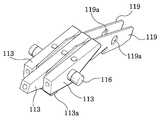
여기서, 상기 가동자(113)의 종래 구조는 도 3A와 도 3B에 도시된 것과 같이, 상기 가동자(113)는 그 일측 하단에 상기 기중 차단기(100)의 투입 동작시 상기 고정접점(120a)과 접촉하는 가동접점(113a)이 설치되고, 상기 가동자(113)의 측부에는 설정된 통전용량에 따라 다수의 가동자(113)들을 관통하는 피봇핀(116)이 설치되며, 상기 가동자(113)와 가동자(113) 사이에는 각각 암가이드(119)가 설치되고, 상기 암가이드(119)는 상기 가동자(113)의 회전중심을 위해 설치되는 회전핀(114)의 고정을 위한 회전핀 고정홀(119a)이 형성된다.Here, the conventional structure of the
즉, 상기의 구성으로 이루어진 기중 차단기(100)는 절연암(112)이 투입 및 차단을 위해 상기 기구부에서 발생한 힘을 통전부의 상기 가동자(113)에 전달하는 기능을 수행함과 동시에 정격 통전, 단락사고시 통전부에서 기구부로 유입될 수 있는 전류를 차단해주는 역할을 동시에 담당하고 있다.That is, the
그러나, 단락사고와 같은 경우, 차단 동작시 상기 가동접점(113a이 고정접점(120a)으로부터 개리를 시작하며 아크가 발생되고, 이 아크로 인해 상기 소호부(140)내에는 다량의 이물질을 함유한 고온, 고압의 가스가 발생하게 되며, 이로 인해 상기 통전부와 기구부의 절연성 유지를 장담할 수 없게 된다. 이것은 상기 기중 차단기(100)의 통전부 뿐만아니라 기구부의 손상까지 가져올 수 있으며 이는 기중 차단기(100)의 성능저하와 직결된다.However, in the case of a short circuit accident, an arc is generated when the
또한, 차단동작을 완료한 상태에서도 상기 접압스프링(118)은 일정한 압축력을 가지고 있어 투입동작시 상기 기구부의 부담을 가중시키게 된다.In addition, even when the blocking operation is completed, the
그리고, 다수의 가동자(113)로 구성되는 기중 차단기(100)의 특성상 가동자(113)의 개별적인 동작을 위해 가동자(113) 사이는 일정한 거리를 유지하고 있어야 하며, 이에 따라 상기 가동자(113)간의 간격유지를 위해 스페이서 역할을 수행하는 추가부품의 설치가 불가피하기 때문에 부품수의 증가로 원가상승 요인을 가져오는 단점이 있다.In addition, for the individual operation of the
이에 본 발명은 종래의 기중 차단기가 갖는 문제점을 해소하기 위해 안출된 것으로, 통전시 통전부와 기구부간의 절연상태를 유지함과 아울러 추가 부품없이 차단기 가동자간의 거리를 유지시킬 수 있도록 한 기중 차단기의 가동부 구조를 제공함에 그 목적이 있다.Accordingly, the present invention has been made to solve the problems of the conventional air circuit breaker, the moving part of the air circuit breaker to maintain the distance between the circuit breaker operator without additional parts to maintain the insulation state between the current-carrying part and the mechanism part when energized The purpose is to provide a structure.
상기한 바의 목적을 달성하기 위한 본 발명은, 기구부와 연결된 링크를 매개로 연결핀을 통해 회전가능하도록 구속되면서 일측단부에는 회전중심을 고정해주는 회전핀이 설치됨과 아울러 내측 저면에는 다수의 스프링 삽입홈이 형성된 절연 케이지와, 상기 절연 케이지의 하부에 피봇핀으로 회동가능하게 연결됨과 아울러 그 상부에 상기 스프링 삽입홈과 대응되는 스프링 고정홈이 형성되고 하부에는 상기 절연 케이지의 회전을 통해 입력측 터미널의 고정접점과 접촉될 수 있는 가동접점이 설치된 다수의 가동자와, 상기 절연 케이지의 스프링 삽입홈과 상기 가동자 사이에 설치되어 가동자의 압축력을 통해 가동자와 입력측 터미널 사이에 일정한 접압력을 유지시키도록 하는 접압스프링을 포함하여 구성된 기중 차단기의 가동부 구조에 있어서, 상기 가동자의 일측면에는 각각의 가동자가 일정간격을 유지하면서 배치되도록 요철이 돌출형성되고, 상기 요철은 상기 피봇핀의 삽입을 위한 고정홀을 중심으로 그 좌우측에 각각 형성된 구성이다.The present invention for achieving the above object is, while being constrained to be rotatable through a connecting pin via a link connected to the mechanism portion, one side end is provided with a rotation pin for fixing the center of rotation and a plurality of springs inserted into the inner bottom An insulating cage having a groove formed therein and a pivot pin connected to the lower portion of the insulating cage in a rotatable manner, and a spring fixing groove corresponding to the spring insertion groove is formed at an upper portion thereof, and a lower portion of the input side terminal is rotated through the rotation of the insulating cage. A plurality of movers provided with movable contacts capable of contact with the fixed contact point are installed between the spring insertion groove of the insulating cage and the mover to maintain a constant contact pressure between the mover and the input terminal through the compressive force of the mover. In the structure of the movable part of the air circuit breaker comprising a contact spring to Group one side of the mover is formed to project and uneven so as to be disposed while maintaining a predetermined distance, each of the mover, wherein the concave-convex configuration is formed on each of the left and right around the fixing hole for the insertion of the pivot pin.
그리고, 상기 절연 케이지는 상부에 돌출부가 형성되어 차단동작과 동시에 돌출부가 상기 상부 몰드케이스의 상단개구부를 막아줄 수 있다.In addition, the insulating cage may have a protrusion formed at an upper portion thereof, and at the same time as the blocking operation, the protrusion may block an upper opening of the upper mold case.
또한, 상기 절연 케이지는 그 몸체가 소호 재질인 개싱 머티리얼(gassing material)로 구성된다.In addition, the insulating cage is composed of a gassing material whose body is an extinguishing material.
이하 본 발명을 첨부된 예시도면을 참조하여 상세히 설명한다.Hereinafter, the present invention will be described in detail with reference to the accompanying drawings.
전기회로에 있어서 발생 가능한 단락, 지락 등의 사고전류로부터 부하기기 및 선로를 보호하도록 된 기중 차단기는 가동부가 설치되는 바, 상기 가동부의 구조를 도 4와 도 5를 참조로 설명하면, 상기 기중 차단기(1)는 기구부의 연결을 위한 상단개구부(10a)가 형성된 상부 몰드케이스(10)와, 고정접점(20a)을 포함하는 입력측 터미널(20) 및 션트(31)가 연결되는 부하측 터미널(30)이 각각 설치된 하부 몰드케이스(40)와, 상기 기구부의 메커니즘으로부터 힘을 전달받는 가동부(50)와, 상기 가동부(50)의 일측에서 공간을 이루는 소호부(60)를 포함하여 구성된다.The air circuit breaker designed to protect the load device and the line from an accidental current such as a short circuit or ground fault that may occur in an electric circuit is provided with a movable part. The structure of the movable part will be described with reference to FIGS. 4 and 5. 1 is an
즉, 상기 기중 차단기(1)는 정격전류 통전시 상기 소호부(60) 및 가동부(50)가 상기 상부 몰드케이스(10)와 하부 몰드케이스(40)내의 공간에 배치된다.That is, the
그리고, 상기 가동부(50)는 크게 본체를 구성하면서 절연재료로 성형된 절연 케이지(51)와, 상기 절연 케이지(51)에 회동가능하게 조립되는 다수의 가동자(52) 및, 상기 가동자(52)에 접압력을 부여하는 접압스프링(53)으로 구성된다.In addition, the
상기 절연 케이지(51)는 상기 기구부와 연결된 링크(54)를 매개로 연결핀(55)을 통해 회전가능하도록 구속되고, 상기 절연 케이지(51)의 일측단부에는 회전중심을 고정해주는 회전핀(56)이 설치되며, 상기 절연 케이지(51)의 내측 저면에는 다수의 스프링 삽입홈(도시되지 않음)이 형성된다.The insulating
상기 가동자(52)는 상기 절연 케이지(51)의 하부에 피봇핀(57)으로 회동가능하게 연결설치되고, 상기 가동자(52)의 상부에는 상기 스프링 삽입홈과 대응되는 스프링 고정홈(52d, 도 6B 참조)이 형성되며, 상기 가동자(52)의 일측면에 스페이서가 일체로 형성되어 다수의 가동자(52)가 일정간격을 유지하면서 배치된다.The
상기 접압스프링(53)은 상기 가동자(52)의 압축력을 통해 상기 가동자(52)와 상기 입력측 터미널(20) 사이에 일정한 접압력을 유지시키도록 구성된다.The
여기서, 상기 가동자(52)는 다수개로 이루어지고 각 가동자(52)에는 상기 스페이서가 일체로 형성되어 각각의 가동자(52)가 일정간격을 유지하면서 배치되고, 또한 상기 가동자(52)는 상기 기구부로부터 전달되는 투입력에 의해 상기 접압스프링(53)을 압축시킨다.Here, the
또한, 상기 절연 케이지(51)는 상기 상하부 몰드케이스(10,40)에 고정된 상 기 회전핀(56)을 통해 회동가능하게 설치되고, 상기 가동자(52)는 상기 부하측 터미널(30)과 션트(31)로 연결되고, 상기 가동자(52)에 설치된 가동접점(52a)은 상기 입력측 터미널(20)의 고정접점(20a)과 접촉하여 입력측 터미널(20)에서 들어온 전류는 상기 부하측 터미널(30)로 흘려보내게 된다.In addition, the insulating
한편, 단락 혹은 이상전류시 상기 기중 차단기(1)의 트립부에서 사고전류를 감지하여 상기 기구부에 트립래치 해제신호를 보내게 되고, 이와 동시에 상기 기구부와 연결된 링크(54)에 투입력을 가하고 있던 기구부의 래치가 해제되면서 압축되어 있던 상기 접압스프링(53)의 압축력에 의해 상기 가동자(52)와 절연 케이지(51)가 상기 회전핀(56)을 중심으로 시계방향 회전운동을 시작하게 된다. 이에 따라 상기 가동접점(52a)이 고정접점(20a)으로부터 개리를 시작하여 차단동작을 수행한다.On the other hand, in the event of a short circuit or an abnormal current, the tripping part of the
상기 차단동작과 동시에 상기 절연 케이지(51)는 상부 몰드케이스(10)의 상단개구부(10a)를 차단할 수 있도록 구성되는 바, 즉 상기 절연 케이지(51)는 상부에 돌출부(51a)가 형성되어 차단동작과 동시에 돌출부(51a)가 상기 상부 몰드케이스(10)의 상단개구부(10a)를 막아줄 수 있고, 이를 통해 통전시 상기 기구부와 통전부 사이의 절연상태를 유지할 수 있게 된다.At the same time as the blocking operation, the insulating
그리고, 상기 접점의 개리로 발생하는 아크에 의해 짧은 시간내에 압력가스가 상기 소호부(60)의 좌측 내부를 채우게 되고, 상기 압력가스는 케이스의 배출구(61)를 통해 빠져나가게 된다.In addition, the pressure gas fills the left side of the extinguishing
또한, 상기 절연 케이지(51)는 그 재질을 소호 재질인 개싱 머티리얼로 사용하여 아크발생시 소호 재질이 연소되면서 아크소호에 도움이 되는 개스를 발생시켜 주게 되어 아크 소호능력이 배가되기 때문에 매우 효과적이며, 상기 소호 재질의 예로는 나일론66(Nylon-66), 테프론(Teflon), MC-Nylon, POM 등이 있다.In addition, the insulating
여기서, 상기 가동부(50)를 이루는 가동자(52)의 구조는 도 6A와 도 6B에 도시된 것과 같이, 상기 가동자(52)는 상기 피봇핀(57)이 삽입될 수 있는 고정홀(52b)이 형성됨과 아울러 그 하단에 가동접점(52a)이 돌출되어 상기 절연 케이지(51)의 회전을 통해 상기 입력측 터미널(20)의 고정접점(20a)과 접촉될 수 있고, 상기 스페이서는 상기 가동자(52)의 고정홀(52b)을 중심으로 좌우측에 각각 형성된 요철(52c)로 구성된다.In this case, as shown in FIGS. 6A and 6B, the
즉, 상기 기중 차단기(1)의 정격 전류에 따라 설치되는 상기 가동자(52)들은 상기 피봇핀(57)을 통해 일정 간격을 두고 연결되며, 상기 가동자(52)의 일측면에는 다수의 요철(52c)이 일체로 형성되어 다수의 가동자(52)간 거리를 일정하게 유지시켜 준다. 또한 상기 가동자(52)들은 독립적인 회전운동을 수행한다.That is, the
따라서, 상기 가동부(50)의 절연 케이지(51)와 피봇핀(57)으로 연결되는 상기 가동자(52)들은 상기 요철(52c)로 인해 서로 일정한 간격을 유지하면서 개별 동작이 가능하도록 구성된다.Therefore, the
이상에서 설명한 바와 같이 본 발명에 따른 기중 차단기의 가동부 구조에 의하면, 가동부의 차단동작시 아크나 압력가스가 기구부로 유입되는 것을 방지함으로써 기구부가 손상되는 것을 방지할 수 있고, 다수의 가동자들이 추가 부품 없이도 설정된 동작범위내에서 가동자간 일정한 거리를 유지할 수 있게 추가 부품의 삭제 에 따른 원가를 절감할 수 있다.As described above, according to the movable part structure of the air circuit breaker according to the present invention, it is possible to prevent damage to the mechanical part by preventing arc or pressure gas from flowing into the mechanical part during the blocking operation of the movable part. The cost of eliminating additional parts can be reduced to maintain a certain distance between the movers within the set operating range without parts.
Claims (3)
Translated fromKoreanPriority Applications (1)
| Application Number | Priority Date | Filing Date | Title |
|---|---|---|---|
| KR1020060008852AKR100701776B1 (en) | 2006-01-27 | 2006-01-27 | Moving part structure of the air circuit breaker |
Applications Claiming Priority (1)
| Application Number | Priority Date | Filing Date | Title |
|---|---|---|---|
| KR1020060008852AKR100701776B1 (en) | 2006-01-27 | 2006-01-27 | Moving part structure of the air circuit breaker |
Publications (1)
| Publication Number | Publication Date |
|---|---|
| KR100701776B1true KR100701776B1 (en) | 2007-03-30 |
Family
ID=41565307
Family Applications (1)
| Application Number | Title | Priority Date | Filing Date |
|---|---|---|---|
| KR1020060008852AExpired - Fee RelatedKR100701776B1 (en) | 2006-01-27 | 2006-01-27 | Moving part structure of the air circuit breaker |
Country Status (1)
| Country | Link |
|---|---|
| KR (1) | KR100701776B1 (en) |
Cited By (2)
| Publication number | Priority date | Publication date | Assignee | Title |
|---|---|---|---|---|
| KR100911968B1 (en) | 2007-08-20 | 2009-08-13 | 엘에스산전 주식회사 | Operation contactor of lift breaker |
| WO2023167410A1 (en)* | 2022-03-03 | 2023-09-07 | 엘에스일렉트릭 (주) | Air circuit breaker |
Citations (4)
| Publication number | Priority date | Publication date | Assignee | Title |
|---|---|---|---|---|
| KR940016336A (en)* | 1992-12-08 | 1994-07-23 | 성기설 | Current limiting device of circuit breaker |
| KR20000015647A (en)* | 1998-08-31 | 2000-03-15 | 이종수 | Circuit breaker |
| KR20020045251A (en)* | 2000-12-08 | 2002-06-19 | 이종수 | Mccd moving contactor |
| JP2005353404A (en)* | 2004-06-10 | 2005-12-22 | Fuji Electric Fa Components & Systems Co Ltd | Circuit breaker |
- 2006
- 2006-01-27KRKR1020060008852Apatent/KR100701776B1/ennot_activeExpired - Fee Related
Patent Citations (4)
| Publication number | Priority date | Publication date | Assignee | Title |
|---|---|---|---|---|
| KR940016336A (en)* | 1992-12-08 | 1994-07-23 | 성기설 | Current limiting device of circuit breaker |
| KR20000015647A (en)* | 1998-08-31 | 2000-03-15 | 이종수 | Circuit breaker |
| KR20020045251A (en)* | 2000-12-08 | 2002-06-19 | 이종수 | Mccd moving contactor |
| JP2005353404A (en)* | 2004-06-10 | 2005-12-22 | Fuji Electric Fa Components & Systems Co Ltd | Circuit breaker |
Cited By (4)
| Publication number | Priority date | Publication date | Assignee | Title |
|---|---|---|---|---|
| KR100911968B1 (en) | 2007-08-20 | 2009-08-13 | 엘에스산전 주식회사 | Operation contactor of lift breaker |
| WO2023167410A1 (en)* | 2022-03-03 | 2023-09-07 | 엘에스일렉트릭 (주) | Air circuit breaker |
| KR20230130265A (en)* | 2022-03-03 | 2023-09-12 | 엘에스일렉트릭(주) | Air circuit breaker having insulation paper to prevent terminal short circuit |
| KR102788607B1 (en)* | 2022-03-03 | 2025-03-28 | 엘에스일렉트릭(주) | Air circuit breaker having insulation paper to prevent terminal short circuit |
Similar Documents
| Publication | Publication Date | Title |
|---|---|---|
| US7148775B2 (en) | Contactor assembly for circuit breaker | |
| CN101303946B (en) | Electrical switching apparatus, and conductor assembly and shunt assembly therefor | |
| US6403909B1 (en) | Trip override for rotary breaker | |
| KR100662752B1 (en) | Multipole Wiring Breakers | |
| EP1442466B1 (en) | Low-voltage circuit breaker | |
| KR100701775B1 (en) | Movable contactor of air circuit breaker | |
| KR20090050964A (en) | Magnetic trip device for circuit breakers and circuit breakers | |
| KR100701776B1 (en) | Moving part structure of the air circuit breaker | |
| KR200156760Y1 (en) | Current limiting device of circuit breaker | |
| CA1331998C (en) | Circuit breaker with low voltage contact structure | |
| EP1218899B1 (en) | Electric pole for low-voltage power circuit breaker | |
| KR200190795Y1 (en) | Limiting current device of a circuit breaker | |
| KR100290932B1 (en) | device for limiting current of molded case circuit breaker | |
| KR101010090B1 (en) | Circuit breaker with trip device using gas pressure and magnetic force | |
| KR100890755B1 (en) | Shaft assembly of wiring breaker and single-pole breaking unit with same | |
| KR100732508B1 (en) | Pressure trip device of circuit breaker | |
| JP7718217B2 (en) | circuit breaker | |
| KR100720791B1 (en) | Sequential Circuit Breaker Using Rotating Body With Contact | |
| KR100652234B1 (en) | Trip device of circuit breaker | |
| KR100557495B1 (en) | Gas pressure trip device of circuit breaker | |
| KR100662753B1 (en) | Trip device of circuit breaker | |
| EP1346385B1 (en) | Automatic current limiting circuit breaker | |
| KR100379691B1 (en) | Contact point closing/open apparatus for circuit breaker | |
| KR100610952B1 (en) | Sequential trip breaker | |
| KR200156758Y1 (en) | Switchgear mechanism of wiring breaker |
Legal Events
| Date | Code | Title | Description |
|---|---|---|---|
| A201 | Request for examination | ||
| PA0109 | Patent application | St.27 status event code:A-0-1-A10-A12-nap-PA0109 | |
| PA0201 | Request for examination | St.27 status event code:A-1-2-D10-D11-exm-PA0201 | |
| D13-X000 | Search requested | St.27 status event code:A-1-2-D10-D13-srh-X000 | |
| D14-X000 | Search report completed | St.27 status event code:A-1-2-D10-D14-srh-X000 | |
| E701 | Decision to grant or registration of patent right | ||
| PE0701 | Decision of registration | St.27 status event code:A-1-2-D10-D22-exm-PE0701 | |
| PR1002 | Payment of registration fee | St.27 status event code:A-2-2-U10-U11-oth-PR1002 Fee payment year number:1 | |
| GRNT | Written decision to grant | ||
| PR0701 | Registration of establishment | St.27 status event code:A-2-4-F10-F11-exm-PR0701 | |
| PG1601 | Publication of registration | St.27 status event code:A-4-4-Q10-Q13-nap-PG1601 | |
| R18-X000 | Changes to party contact information recorded | St.27 status event code:A-5-5-R10-R18-oth-X000 | |
| R18-X000 | Changes to party contact information recorded | St.27 status event code:A-5-5-R10-R18-oth-X000 | |
| R18-X000 | Changes to party contact information recorded | St.27 status event code:A-5-5-R10-R18-oth-X000 | |
| PR1001 | Payment of annual fee | St.27 status event code:A-4-4-U10-U11-oth-PR1001 Fee payment year number:4 | |
| PN2301 | Change of applicant | St.27 status event code:A-5-5-R10-R13-asn-PN2301 St.27 status event code:A-5-5-R10-R11-asn-PN2301 | |
| PR1001 | Payment of annual fee | St.27 status event code:A-4-4-U10-U11-oth-PR1001 Fee payment year number:5 | |
| PN2301 | Change of applicant | St.27 status event code:A-5-5-R10-R13-asn-PN2301 St.27 status event code:A-5-5-R10-R11-asn-PN2301 | |
| PR1001 | Payment of annual fee | St.27 status event code:A-4-4-U10-U11-oth-PR1001 Fee payment year number:6 | |
| R18-X000 | Changes to party contact information recorded | St.27 status event code:A-5-5-R10-R18-oth-X000 | |
| FPAY | Annual fee payment | Payment date:20121221 Year of fee payment:7 | |
| PN2301 | Change of applicant | St.27 status event code:A-5-5-R10-R13-asn-PN2301 St.27 status event code:A-5-5-R10-R11-asn-PN2301 | |
| PR1001 | Payment of annual fee | St.27 status event code:A-4-4-U10-U11-oth-PR1001 Fee payment year number:7 | |
| FPAY | Annual fee payment | Payment date:20131218 Year of fee payment:8 | |
| PR1001 | Payment of annual fee | St.27 status event code:A-4-4-U10-U11-oth-PR1001 Fee payment year number:8 | |
| FPAY | Annual fee payment | Payment date:20150106 Year of fee payment:9 | |
| PR1001 | Payment of annual fee | St.27 status event code:A-4-4-U10-U11-oth-PR1001 Fee payment year number:9 | |
| R18-X000 | Changes to party contact information recorded | St.27 status event code:A-5-5-R10-R18-oth-X000 | |
| FPAY | Annual fee payment | Payment date:20160225 Year of fee payment:10 | |
| PR1001 | Payment of annual fee | St.27 status event code:A-4-4-U10-U11-oth-PR1001 Fee payment year number:10 | |
| P22-X000 | Classification modified | St.27 status event code:A-4-4-P10-P22-nap-X000 | |
| LAPS | Lapse due to unpaid annual fee | ||
| PC1903 | Unpaid annual fee | St.27 status event code:A-4-4-U10-U13-oth-PC1903 Not in force date:20170324 Payment event data comment text:Termination Category : DEFAULT_OF_REGISTRATION_FEE | |
| PC1903 | Unpaid annual fee | St.27 status event code:N-4-6-H10-H13-oth-PC1903 Ip right cessation event data comment text:Termination Category : DEFAULT_OF_REGISTRATION_FEE Not in force date:20170324 | |
| PN2301 | Change of applicant | St.27 status event code:A-5-5-R10-R13-asn-PN2301 St.27 status event code:A-5-5-R10-R11-asn-PN2301 | |
| PN2301 | Change of applicant | St.27 status event code:A-5-5-R10-R13-asn-PN2301 St.27 status event code:A-5-5-R10-R11-asn-PN2301 | |
| R18-X000 | Changes to party contact information recorded | St.27 status event code:A-5-5-R10-R18-oth-X000 |