KR100700944B1 - High frequency organic power charging device and method for portable terminal - Google Patents
High frequency organic power charging device and method for portable terminalDownload PDFInfo
- Publication number
- KR100700944B1 KR100700944B1KR1020050004939AKR20050004939AKR100700944B1KR 100700944 B1KR100700944 B1KR 100700944B1KR 1020050004939 AKR1020050004939 AKR 1020050004939AKR 20050004939 AKR20050004939 AKR 20050004939AKR 100700944 B1KR100700944 B1KR 100700944B1
- Authority
- KR
- South Korea
- Prior art keywords
- power
- antenna
- high frequency
- antennas
- frequencies
- Prior art date
- Legal status (The legal status is an assumption and is not a legal conclusion. Google has not performed a legal analysis and makes no representation as to the accuracy of the status listed.)
- Expired - Fee Related
Links
Images

Classifications
- H—ELECTRICITY
- H02—GENERATION; CONVERSION OR DISTRIBUTION OF ELECTRIC POWER
- H02J—CIRCUIT ARRANGEMENTS OR SYSTEMS FOR SUPPLYING OR DISTRIBUTING ELECTRIC POWER; SYSTEMS FOR STORING ELECTRIC ENERGY
- H02J7/00—Circuit arrangements for charging or depolarising batteries or for supplying loads from batteries
- H—ELECTRICITY
- H04—ELECTRIC COMMUNICATION TECHNIQUE
- H04B—TRANSMISSION
- H04B1/00—Details of transmission systems, not covered by a single one of groups H04B3/00 - H04B13/00; Details of transmission systems not characterised by the medium used for transmission
- H04B1/06—Receivers
- H04B1/16—Circuits
- H04B1/1607—Supply circuits
- H—ELECTRICITY
- H04—ELECTRIC COMMUNICATION TECHNIQUE
- H04B—TRANSMISSION
- H04B1/00—Details of transmission systems, not covered by a single one of groups H04B3/00 - H04B13/00; Details of transmission systems not characterised by the medium used for transmission
- H04B1/38—Transceivers, i.e. devices in which transmitter and receiver form a structural unit and in which at least one part is used for functions of transmitting and receiving
- H04B1/40—Circuits
Landscapes
- Engineering & Computer Science (AREA)
- Computer Networks & Wireless Communication (AREA)
- Signal Processing (AREA)
- Power Engineering (AREA)
- Telephone Function (AREA)
- Charge And Discharge Circuits For Batteries Or The Like (AREA)
Abstract
Translated fromKoreanDescription
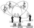
Translated fromKorean도 1은 일상 생활에서 흔히 접할 수 있는 유기전력들의 예를 보여주는 도면.1 illustrates examples of organic powers commonly encountered in everyday life.
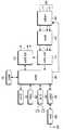
도 2는 본 발명의 실시예에 따른 휴대용 통신단말기의 블록 구성을 도시하는 도면.2 is a block diagram of a portable communication terminal according to an embodiment of the present invention.
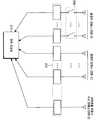
도 3은 본 발명에 따른 안테나 어레이(208), 스위칭부(209), 정류부(210) 및 전력저장부(211)의 연결관계를 도시하는 도면.3 is a diagram illustrating a connection relationship between an
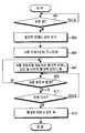
도 4는 본 발명의 실시예에 따른 휴대용 단말기에서 공중에 유기된 고주파 전력을 수신하는 안테나 어레이의 동작을 제어하기 위한 절차를 도시하는 도면.4 is a diagram illustrating a procedure for controlling an operation of an antenna array for receiving high frequency power induced in the air in a portable terminal according to an embodiment of the present invention.
도 5는 본 발명의 적용에 따른 댁내 무선 전력 공급의 일 예를 보여주는 도면.5 is a view showing an example of an indoor wireless power supply according to the application of the present invention.
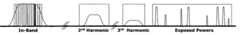
도 6은 능동소자(active device)에서 생성되는 하모닉 전력의 일 예를 보여주는 도면.FIG. 6 illustrates an example of harmonic power generated in an active device. FIG.
본 발명은 휴대용 단말기의 전력 충전 장치 및 방법에 관한 것으로, 특히 고주파 유기전력을 충전하기 위한 장치 및 방법에 관한 것이다.The present invention relates to a power charging device and method of a portable terminal, and more particularly to a device and method for charging high frequency organic power.
1947년 Bell Lab에서 고안되고 1979년 일본에서 처음으로 1G(1st generation) 셀룰라 통신(Cellular Communication)이 상용화된 이래 이동통신은 2G, 2.5G, 3G를 거쳐 휴대인터넷, DMB(Digital Multimedia Broadcasting), 유비쿼터스(Ubiquitous) 네트워크 서비스 등 급격히 발전하고 있다. 원하든 원하지 않든 많은 전자파 환경에 노출되고 있고 전자파의 인체 유해 여부에 관한 연구도 활발히 진행되고 있다.Designed by Bell Lab in 1947 and the first commercialization of 1G (1st generation) Cellular Communication in 1979 in Japan, mobile communication has gone through 2G, 2.5G, and 3G, and has resulted in mobile Internet, Digital Multimedia Broadcasting (DMB) (Ubiquitous) Network services are developing rapidly. Whether you want it or not, it is exposed to many electromagnetic environments, and there are active researches on whether electromagnetic waves are harmful to humans.
또한, 디지털 컨버젼스(Digital Convergence)의 확대로 휴대 단말기의 여러 가지 기능이 구현됨으로써 그만큼 전력 소비량이 증가하는 추세이다. 더욱이, 고속의 멀티미디어(multimedia) 이동통신 서비스가 발전하면서 셀 폰(cell phone), 랩탑 컴퓨터(Laptop computer) 등 휴대 단말기의 전력 소모량은 점점 증가하고 있다. 따라서, 저전력으로 동작하는 집적회로(IC : Integrated Circuit)와 대용량의 배터리(Battery)는 향후 휴대단말기의 발전에 있어 큰 이슈(issue)가 될 것이다. 궁극적으로는, Charge-Free 단말기에 대한 개발이 큰 이슈가 될 것이다.In addition, as the digital convergence expands, various functions of the mobile terminal are implemented, thereby increasing power consumption. In addition, with the development of high-speed multimedia mobile communication services, the power consumption of portable terminals such as cell phones and laptop computers is increasing. Therefore, integrated circuits (ICs) and large-capacity batteries that operate at low power will become a big issue in the development of portable terminals in the future. Ultimately, the development of charge-free terminals will be a big issue.
근래에, 고속의 이동통신 서비스를 원활하게 제공하기 위해서 셀 반경이 나노(Nano) 혹은 피코(Pico) 셀 등과 같이 점점 작아지고, 또한 다양한 서비스 대역들로 인해 전자파의 노출이 점점 심화되는 추세이다. 따라서 이렇게 공중에 유기된 다양한 고주파(RF, 마이크웨이브(Microwave)) 전력들을 적극 활용할수 있는 방안이 요구되고 있다.In recent years, in order to smoothly provide a high speed mobile communication service, a cell radius becomes smaller and smaller, such as a nano or pico cell, and exposure to electromagnetic waves is intensified due to various service bands. Therefore, there is a demand for a method that can actively utilize various high frequency (RF, microwave) powers induced in the air.
따라서 본 발명의 목적은 휴대용 단말기에서 유기된 고주파를 DC변환한후 전력으로 충전하기 위한 장치 및 방법을 제공함에 있다.Accordingly, an object of the present invention is to provide an apparatus and method for charging with high power after DC conversion of high frequency induced in a portable terminal.
상기 목적을 달성하기 위한 본 발명의 실시예에 따르면, 휴대용 단말기에서 고주파 유기 전력을 충전하기 위한 장치가, 공중에 유기된 고주파 신호들을 수신하기 위한 안테나 어레이와, 상기 안테나 어레이를 통해 수신되는 고주파 신호들을 DC전압으로 변환하기 위한 정류부와, 상기 정류부로부터의 DC전압들을 전력으로 축적하기 위한 전력저장부를 포함하는 것을 특징으로 한다.According to an embodiment of the present invention for achieving the above object, an apparatus for charging high frequency organic power in a portable terminal, an antenna array for receiving the high frequency signals induced in the air, and a high frequency signal received through the antenna array And a power storage unit for accumulating the DC voltages from the rectifier into electric power.
바람직하기로, 상기 안테나 어레이는, 통신용 사용 주파수 대역의 채널주파수들 및 상기 사용 주파수 대역의 주변 주파수들을 각각 수신하기 위한 협대역 안테나들과, 상기 사용 주파수 대역과 떨어진 주파수들을 수신하기 위한 광대역 안테나들을 포함하여 구성되는 것을 특징으로 한다.Advantageously, the antenna array comprises narrowband antennas for receiving channel frequencies in a communication frequency band for communication and surrounding frequencies in the frequency band for use, and broadband antennas for receiving frequencies apart from the frequency band for use. Characterized in that it comprises a.
바람직하기로, 능동소자(active device)에 의해 발생하는 하모닉(harmonic) 주파수들을 추출하기 위한 필터들과, 상기 필터들로부터의 하모닉 주파수들을 DC전압으로 변환하여 상기 전력저장부에 축적하기 위한 정류부를 더 포함하는 것을 특징으로 한다.Preferably, filters for extracting harmonic frequencies generated by an active device, and a rectifier for converting the harmonic frequencies from the filters to a DC voltage to accumulate in the power storage unit It further comprises.
바람직하기로, 상기 안테나 어레이를 구성하는 안테나들중 특정 안테나는 댁내 무선 전력 전달용으로 정해진 특정 고주파 신호를 수신하기 위한 안테나로 구성 되는 것을 특징으로 한다.
Preferably, the specific antenna of the antenna constituting the antenna array is characterized in that it is composed of an antenna for receiving a specific high-frequency signal determined for wireless power transfer in the home.
이하 본 발명의 바람직한 실시 예를 첨부된 도면의 참조와 함께 상세히 설명한다. 본 발명을 설명함에 있어서, 관련된 공지기능 혹은 구성에 대한 구체적인 설명이 본 발명의 요지를 불필요하게 흐릴 수 있다고 판단된 경우 그 상세한 설명은 생략한다.Hereinafter, exemplary embodiments of the present invention will be described in detail with reference to the accompanying drawings. In describing the present invention, if it is determined that the detailed description of the related known function or configuration may unnecessarily obscure the subject matter of the present invention, the detailed description thereof will be omitted.
이하 본 발명은 휴대용 단말기에서 유기된 고주파를 DC변환한후 전력으로 충전하기 위한 방안에 대해 설명하기로 한다. 상기 휴대용 단말기는 휴대용 통신단말기, MP3 플레이어, 노트북(Notebook), 리모트컨트롤러 등과 같은 전력 충전(혹은 배터리 충전)을 요구하는 휴대용 기기를 모두 포함하는 의미이다. 이하 설명은 휴대용 통신단말기를 예를들어 설명하기로 한다.Hereinafter, the present invention will be described with respect to a method for charging with power after DC conversion of the high frequency induced in the portable terminal. The portable terminal is meant to include all portable devices that require power charging (or battery charging) such as a portable communication terminal, an MP3 player, a notebook, a remote controller, and the like. The following description will be made by way of example of a portable communication terminal.
도 1은 일상 생활에서 흔히 접할 수 있는 유기전력들의 예를 보여준다.1 shows examples of organic powers commonly encountered in daily life.
도시된 바와 같이, A 사용자는 자신이 사용하는 주파수 주변의 같은 프로토콜(Protocol)의 다른 밴더(Vendor) 주파수(B사용자 주파수) 또는 다른 프로토콜의 다른 주파수(C사용자 주파수) 등 다양한 주파수의 유기전력에 노출되게 된다. 본 발명은 이러한 주파수에 조정된 안테나를 이용하여 공중(air)에 유기된 고주파 전력을 단말기 내부의 전력저장회로(power storing circuit)에 축적(integration)하는 것을 특징으로 한다.As shown, user A may be exposed to various frequencies of induced power, such as other vendor frequencies (B user frequency) of the same protocol or other frequencies (C user frequency) of other protocols around the frequencies he uses. Exposed. The present invention is characterized by integrating high frequency power induced in the air into a power storing circuit inside a terminal using an antenna tuned to such a frequency.
도 2는 본 발명의 실시예에 따른 휴대용 통신단말기의 블록 구성을 도시하고 있다. 이하 설명에서 상기 휴대용 통신단말기는 셀룰라 전화기(cellular phone), 개인휴대통신 전화기(PCS : Personal Communication system), 복합무선단말기(PDA : Personal Data Assistant), IMT2000(international mobile communication-2000) 단말기, 4G(OFDM : Orthogonal Frequency Division Multiplexing)단말기 등을 모두 포함하는 의미이며, 이하 설명은 상기 예들의 일반적인 구성을 가지고 설명할 것이다.2 is a block diagram of a portable communication terminal according to an embodiment of the present invention. In the following description, the portable communication terminal is a cellular phone, a personal communication system (PCS), a personal digital assistant (PDA), an international mobile communication-2000 (IMT2000) terminal, 4G ( It is meant to include all OFDM (orthogonal frequency division multiplexing) terminals and the like, and the following description will be given with the general configuration of the above examples.
도 2를 참조하면, 먼저 제어부(200)는 상기 단말기의 전반적인 동작을 제어한다. 예를들어, 음성통화 및 데이터통신을 위한 처리 및 제어를 수행하고, 통상적인 기능에 더하여 본 발명에 따라 안테나 어레이(208)를 통해 수신되는 고주파 전력을 전력저장부(211)에 축적하기 위한 기능을 제어한다. 따라서, 이하의 설명에 있어서 통상적인 제어부(200)의 처리 및 제어에 관한 설명은 생략한다.Referring to FIG. 2, first, the
메모리(201)는 프로그램 메모리, 데이터 메모리 및 불휘발성 메모리 등을 포함한다. 상기 프로그램 메모리는 상기 단말기의 전반적인 동작을 제어하기 위한 프로그램을 저장하고 있다. 상기 프로그램 메모리는 플래시 메모리(flash memory)를 사용할 수 있다. 상기 데이터 메모리는 상기 단말기 동작 중에 발생되는 데이터를 일시 저장하는 기능을 수행한다. 상기 데이터 메모리는 램(Random Access Memory)을 사용할 수 있다. 상기 불휘발성 메모리는 시스템 파라미터(system parameter) 및 기타 저장용 데이터(전화번호, SMS 메시지 등)를 저장한다. 상기 불휘발성 메모리는 EEPROM을 사용할 수 있다.The
키패드(key pad)(206)는 0 ∼ 9의 숫자키들과, 메뉴키(menu), 취소키(지움), 확인키, 통화키(TALK), 종료키(END), 인터넷 접속키, 네비게이션 키들(상/하/좌/우) 등 다수의 기능키들을 구비하며, 사용자가 누르는 키에 대응하는 키입력 데이터를 상기 제어부(200)로 제공한다. 표시부(207)는 상기 단말기의 동작 중에 발생되는 상태 정보(또는 인디케이터), 제한된 숫자와 문자들, 동화상(moving picture) 및 정화상(still picture) 등을 디스플레이한다. 상기 표시부(207)는 칼라 액정 디스플레이 장치(LCD : Liquid Crystal Display)를 사용할 수 있다.
상기 제어부(200)에 연결된 오디오 코덱(CODEC : Coder-Decoder)(205)과, 상기 코덱(205)에 접속된 스피커 및 마이크는 음성 통화에 사용되는 음성 입출력 블록이다. 상기 코덱(205)은 상기 제어부(200)에서 제공되는 PCM 데이터를 아날로그 음성신호로 변환하여 상기 스피커를 통해 송출하고, 상기 마이크를 통해 수신되는 음성신호를 PCM데이터로 변환하여 상기 제어부(200)로 제공한다.An audio codec (Coder-Decoder) 205 connected to the
RF부(Radio Frequency module)(203)는 안테나(204)를 통해 수신되는 래디오 주파수(RF) 신호를 주파수 하강시켜 모뎀부(202)로 제공하고, 상기 모뎀부(202)로부터의 기저대역신호를 주파수 상승시켜 상기 안테나를 통해 송신한다. 상기 모뎀부(202)는 상기 RF부(203)와 상기 제어부(200) 사이에 송수신되는 기저대역 신호를 처리한다. 예를들어, 송신인 경우 송신할 데이터를 해당 무선 접속 규격에 따라 채널코딩(channel coding) 및 확산(spreading)하는 기능을 수행하고, 수신인 경우 수신신호를 역확산(despreading) 및 채널복호(channel decoding)하는 기능을 수행한다.The
본 발명에 따른 안테나 어레이(208)는 공중에 유기된 주파수 신호들을 수신 하기 위한 안테나 장치이다. 여기서, 상기 안테나 어레이(208)와 상기 안테나(204)를 하나의 안테나 장치로 구현할수도 있고 별도의 안테나 장치로 구현할수 있다. 상기 안테나 어레이(208)를 구성하는 안테나들중 단말기의 사용 주파수 대역내 채널주파수들과 상기 사용자 주파수 주변의 주파수들을 수신하기 위한 안테나들은 Q(Quality factor : 첨예도)값이 높은 협대역(Narrow band) 안테나를 사용하고, 사용 주파수와 떨어진 주파수 밴드를 수신하기 위한 안테나들은 광대역(Broadband) 안테나를 사용하는 것이 바람직하다. 그 이유는, 스커트(skirt) 특성이 가파르지 않는 광대역 안테나에 의해 상기 사용 주파수의 인밴드(In-band)에 간섭이 발생하는 것을 피하기 위해서이다.The
한편, 본 발명을 구현함에 있어서, 상기 안테나 어레이(208)의 소형화와 성능향상은 무엇보다 중요하다. 협대역 안테나들은 커런트 패스(Current Path)를 조정하고 커플링(Coupling)을 이용해서 소형화와 더불어 밴드의 스커트 특성을 향상시킬 수 있다. 또한, 고유전율의 기판(substrate)을 이용해서 더욱 소형화할수 있다. 최근 안테나 설계 기술의 발달로 더블(double), 트리플(Triple), 쿼드(Quad) 등 멀티 밴드(Multi-Band) 안테나가 가능하게 되었는데, 본 발명은 이러한 멀티 밴드 안테나를 이용하여 구현할수 있다.Meanwhile, in implementing the present invention, miniaturization and performance improvement of the
스위칭부(209)는 상기 제어부(200)의 제어하에 상기 안테나 어레이(208)를 구성하는 안테나들중 협대역 안테나들의 동작을 온/오프 시키는 역할을 수행한다. 여기서, 광대역 안테나들은 사용 주파수에 간섭을 주지 않기 때문에 항상 온(on) 상태를 유지시키는 것으로 가정한다.The
정류부(Rectifier)(210)는 상기 안테나 어레이(208)를 통해 수신되는 복수의 고주파 신호들을 정류시켜 DC전압을 변환하여 출력한다. 상기 정류부(210)는 다이오드(diode) 혹은 RC필터 등으로 구현할수 있으며, 공지의 기술을 사용하는 것으로 가정하기로 한다. 전력저장부(211)는 상기 정류부(210)로부터의 DC전압들을 축적하여 전력을 저장한다. 이렇게 저장된 전력은 전원구동부(212)에 공급되어 단말기의 구동전원으로 이용된다.The
상기 전원구동부(212)는 상기 제어부(200)의 제어하에 상기 전력저장부(211) 및 배터리(도시하지 않음)로부터의 전압을 적정한 레벨로 다운시켜 각 구성으로 전원을 공급 및 공급을 중단하는 역할을 수행한다.The
상술한 구성에서 안테나 어레이(208)와 상기 정류부(210)를 묶어 렉테나(Rectenna)로 구성할수 있다. 그러면, 여기서 본 발명의 핵심이라 할수 있는 상기 안테나 어레이(208), 상기 스위칭부(209), 정류부(210) 및 전력저장부(211)에 대해 보다 상세히 살펴보기로 한다.In the above-described configuration, the
도 3은 본 발명에 따른 안테나 어레이(208), 스위칭부(209), 정류부(210) 및 전력저장부(211)의 연결관계를 도시하고 있다.3 illustrates a connection relationship between the
도시된 바와 같이, 안테나 어레이(208)는 크게 협대역 안테나들(208-1), 광대역 안테나들(208-2) 및 특정 주파수 수신 안테나(208-3)로 구분된다. 상기 협대역 안테나들(208-1)은 사용 주파수 대역내 각 채널주파수(FA : Frequency Allocation)를 수신하기 위한 안테나들 및 상기 사용 주파수 대역 주변의 주파수를 수신하기 위한 안테나들이다. 상기 광대역 안테나들(208-2)은 상기 사용 주파수와 멀리 떨어진 주파수 대역을 수신하기 위한 안테나들이다. 상기 특정 주파수 수신 안테나(208-3)는 무선 전력 전달용 특정 주파수를 수신하기 위한 안테나이다. 상기 무선 전력 전달용 특정 주파수의 운용 방안에 대해서는 이후 도 5의 참조와 함께 상세히 살펴보기로 한다.As shown,
상기 협대역 안테나들(208-1)과 정류부(210) 사이에는 상기 협대역 안테나들의 각각을 온/오프 하기 위한 스위치들(209)이 구비된다. 단말기의 전원이 온(on)되면, 상기 스위치들을 모두 오프(off)시켜 상기 협대역 안테나들의 동작을 모두 오프(off)시킨다. 이후, 통신하기 위한 채널주파수(FA)가 결정되면, 상기 결정된 채널주파수에 대응하는 협대역 안테나를 제외한 나머지 협대역 안테나들의 동작을 온(on)시켜 수신되는 고주파 신호를 정류부(210)를 통해 DC변환하여 전력저장부(211)에 축적한다.Between the narrowband antennas 208-1 and the
이와는 달리, 광대역 안테나들(208-2) 및 특정 주파수 수신 안테나(208-3)는 기지국과 통신하기 위한 사용 주파수에 영향을 주지 않기 때문에 항상 온(on) 상태로 유지한다.In contrast, the wideband antennas 208-2 and the specific frequency receiving antenna 208-3 always remain on because they do not affect the frequency of use for communicating with the base station.
정류부(209)는 각 안테나를 통해 수신되는 고주파 신호를 정류소자(예 : 다이오드)를 이용해 DC전압으로 변환하여 출력한다. 그리고, 상기 전력저장부(211)는 상기 정류부(209)로부터의 DC전압들을 축적하여 전력을 저장한다. 이렇게 저장된 전력은 단말기의 구동전원으로 이용된다.The
도 4는 본 발명의 실시예에 따른 휴대용 단말기에서 공중에 유기된 고주파 전력을 수신하는 안테나 어레이의 동작을 제어하기 위한 절차를 도시하고 있다. 특히, 도 3과 같은 어레이 안테나를 구비할 경우, 상기 협대역 안테나들(208-1)을 선택적으로 동작시키기 위한 절차를 설명하기 위한 것이다.4 illustrates a procedure for controlling an operation of an antenna array for receiving high frequency power induced in the air in a portable terminal according to an embodiment of the present invention. In particular, when providing an array antenna as shown in FIG. 3, a procedure for selectively operating the narrowband antennas 208-1 is described.
도 4를 참조하면, 먼저 제어부(200)는 401단계에서 전원이 온(on)되는지 검사한다. 상기 전원이 온(on)되면, 상기 제어부(200)는 403단계로 진행하여 협대역 안테나들(208-1)의 동작을 모두 오프(off)시킨다. 이후, 상기 제어부(200)는 405단계에서 기지국과 통신하기 위한 채널주파수(FA : Frequency Allocation)를 결정한다.Referring to FIG. 4, first, the
상기 채널주파수가 결정되면, 상기 제어부(200)는 407단계에서 상기 채널주파수에 해당하는 협대역 안테나를 제외한 나머지 협대역 안테나들의 동작을 온(on)시켜 고주파 유기전력을 수신하여 저장한다.When the channel frequency is determined, the
동시에, 상기 제어부(200)는 409단계에서 기지국과 통신하기 위한 채널주파수가 변경되는지 검사한다. 만일, 상기 채널주파수 변경되면, 상기 제어부(200)는 407단계로 되돌아가 해당 채널주파수에 대한 협대역 안테나를 오프(off)시키고 나머지 협대역 안테나들의 동작을 온(on)시켜 고주파 유기전력을 수신하여 저장한다.At the same time, the
만일, 채널주파수의 변경이 감지되지 않으면, 상기 제어부(200)는 411단계로 진행하여 전원이 오프(off)되는지 검사한다. 상기 전원이 오프(off)되지 않으면 상기 제어부(200)는 상기 409단계로 되돌아가고, 상기 전원이 오프(off)되면 상기 제어부(200)는 413단계로 진행하여 협대역 안테나들의 동작을 모두 온(on)시켜 고주파 유기전력을 수신하여 저장한다. 한편, 상술한 알고리즘과 상관없이 광대역 안테 나들(208-2) 및 특정 주파수 수신 안테나(208-3)은 항상 동작하기 때문에 단말기는 항상 고주파 유기전력을 수신하여 저장할수 있다.If the change of the channel frequency is not detected, the
앞서 언급한 바와 같이, 특정 주파수를 이용해 전력을 전달할수 있다. 도 3에서 안테나(208-3)는 특정 주파수를 수신하기 위한 안테나로, 상기 특정 주파수는 전력을 전달하기 위해 정의된 주파수이다. 즉, 이러한 주파수는 댁내(또는 옥내)에서 각각의 기기로 무선 전력을 전달하기 위한 용도로 사용될 수 있다.As mentioned earlier, power can be delivered using specific frequencies. In FIG. 3, the antenna 208-3 is an antenna for receiving a specific frequency, which is a frequency defined for delivering power. In other words, these frequencies can be used to deliver wireless power to each device in the home (or indoor).
도 5는 본 발명의 적용에 따른 댁내 무선 전력 공급의 일 예를 보여주는 도면이다.5 is a diagram illustrating an example of an indoor wireless power supply according to an application of the present invention.
도시된 바와 같이, 유선을 통해 충전하는 방식 대신 댁내의 무선 송신장치(501)를 이용해 댁내 여러 단말기들(502, 503, 504)로 무선 전력을 공급한다. 즉, ISM(industrial/scientific/medical) 밴드 등의 주파수 자원을 이용해 셀(cell) 반경을 작게 하여 무선 전력을 단말기(502, 503, 504)로 전달한다. 높은 주파수를 사용할수록 안테나(혹은 렉테나)의 크기를 줄일 수 있다. 전자파 유해에 대한 방안은 계속 이슈가 되고 발전해 나가겠지만 무선 전력 공급에서도 가장 큰 문제중이 하나이다. 해결 방안으로 댁내의 경우, 송신장치(501)의 송신 안테나가 스마트 안테나에 사용되고 있는 조정 가능한 좁은 빔 패턴(Beam Pattern)을 가질 수 있도록 구현하고, 센서 등을 이용해 해당 단말기로 정확한 빔이 형성되고 단말기와 인체와의 거리를 센싱하여 전력 전달을 제어할수 있도록 구현한다.As shown in the drawing, instead of charging via a wire, the
상술한 본 발명의 실시예는 공중에 유기된 고주파 전력을 수신하여 단말기 내에 축적하는 방안을 설명하고 있다. 다른 실시예로, 단말기내 능동소자(active device) 특성에 의해 발생하는 하모닉(Harmonic) 전력을 DC로 변환하여 전력으로 저장할수 있다. 도 6에 도시된 바와 같이, 신호가 증폭기(Amp)와 같은 능동소자를 통과할 경우 다수의 하모닉 주파수(하모닉 전력)들이 발생하게 된다. 일반적으로, 단말기에서는 능동소자 후단에 필터를 구비시켜 이러한 하모닉 주파수를 제거하고 있다. 본 발명을 적용할 경우, 이러한 하모닉 주파수들을 추출할수 있는 필터를 구비시키고, 상기 필터에 의해 추출된 하모닉 주파수들을 DC변환하여 전력저장부(211)에 저장할수 있다.The embodiment of the present invention described above describes a method of receiving high frequency power induced in the air and accumulating it in a terminal. In another embodiment, the harmonic power generated by the characteristic of the active device in the terminal may be converted into DC and stored as power. As shown in FIG. 6, when a signal passes through an active element such as an amplifier, a plurality of harmonic frequencies (harmonic powers) are generated. In general, the terminal removes such harmonic frequencies by providing a filter at the rear of the active element. In the case of applying the present invention, a filter capable of extracting such harmonic frequencies may be provided, and the harmonic frequencies extracted by the filter may be DC-converted and stored in the
한편 본 발명의 상세한 설명에서는 구체적인 실시예에 관해 설명하였으나, 본 발명의 범위에서 벗어나지 않는 한도 내에서 여러 가지 변형이 가능함은 물론이다. 그러므로 본 발명의 범위는 설명된 실시예에 국한되어 정해져서는 아니 되며 후술하는 특허청구의 범위뿐만 아니라 이 특허청구의 범위와 균등한 것들에 의해 정해져야 한다.Meanwhile, in the detailed description of the present invention, specific embodiments have been described, but various modifications are possible without departing from the scope of the present invention. Therefore, the scope of the present invention should not be limited to the described embodiments, but should be determined not only by the scope of the following claims, but also by those equivalent to the scope of the claims.
상술한 바와 같이, 본 발명은 멀티미디어(Multi-Media) 기능의 향상으로 문제가 되는 배터리 수명시간을 늘리고, 궁극적으로 Charge-Free 단말기를 실현할수 있다. 또한 댁내에서 여러 가지 단말기들로 무선으로 전력을 공급함으로써 유선으로 일일이 충전하는 번거로움을 제거할수 있다. 한편, RFID 같은 저전력 IC에 응용 함으로써 반영구적인 사용시간을 실현할수 있다.As described above, the present invention can increase the battery life time, which is a problem due to the improvement of the multimedia function, and ultimately realize a charge-free terminal. In addition, by supplying power wirelessly to various terminals in the home, it can eliminate the hassle of charging by wire. Meanwhile, semi-permanent use time can be realized by applying to low power IC such as RFID.
Claims (12)
Translated fromKoreanPriority Applications (2)
| Application Number | Priority Date | Filing Date | Title |
|---|---|---|---|
| KR1020050004939AKR100700944B1 (en) | 2005-01-19 | 2005-01-19 | High frequency organic power charging device and method for portable terminal |
| US11/335,446US7606540B2 (en) | 2005-01-19 | 2006-01-19 | Apparatus and method for using ambient RF power in a portable terminal |
Applications Claiming Priority (1)
| Application Number | Priority Date | Filing Date | Title |
|---|---|---|---|
| KR1020050004939AKR100700944B1 (en) | 2005-01-19 | 2005-01-19 | High frequency organic power charging device and method for portable terminal |
Publications (2)
| Publication Number | Publication Date |
|---|---|
| KR20060084228A KR20060084228A (en) | 2006-07-24 |
| KR100700944B1true KR100700944B1 (en) | 2007-03-28 |
Family
ID=36684597
Family Applications (1)
| Application Number | Title | Priority Date | Filing Date |
|---|---|---|---|
| KR1020050004939AExpired - Fee RelatedKR100700944B1 (en) | 2005-01-19 | 2005-01-19 | High frequency organic power charging device and method for portable terminal |
Country Status (2)
| Country | Link |
|---|---|
| US (1) | US7606540B2 (en) |
| KR (1) | KR100700944B1 (en) |
Families Citing this family (234)
| Publication number | Priority date | Publication date | Assignee | Title |
|---|---|---|---|---|
| US8880047B2 (en) | 2005-08-03 | 2014-11-04 | Jeffrey C. Konicek | Realtime, location-based cell phone enhancements, uses, and applications |
| US8295851B2 (en) | 2005-08-03 | 2012-10-23 | Michael Edward Finnegan | Realtime, interactive and geographically defined computerized personal matching systems and methods |
| US9130602B2 (en) | 2006-01-18 | 2015-09-08 | Qualcomm Incorporated | Method and apparatus for delivering energy to an electrical or electronic device via a wireless link |
| US8447234B2 (en) | 2006-01-18 | 2013-05-21 | Qualcomm Incorporated | Method and system for powering an electronic device via a wireless link |
| US7751810B1 (en)* | 2006-03-21 | 2010-07-06 | Nextel Communications Inc. | System and method for transmitting information to subscriber communication units at events |
| KR20090008255A (en)* | 2006-03-22 | 2009-01-21 | 파워캐스트 코포레이션 | Method and apparatus for implementation of wireless power |
| US9022293B2 (en) | 2006-08-31 | 2015-05-05 | Semiconductor Energy Laboratory Co., Ltd. | Semiconductor device and power receiving device |
| WO2008085503A2 (en)* | 2007-01-05 | 2008-07-17 | Powercast Corporation | Powering cell phones and similar devices using rf energy harvesting |
| US9774086B2 (en) | 2007-03-02 | 2017-09-26 | Qualcomm Incorporated | Wireless power apparatus and methods |
| US8482157B2 (en) | 2007-03-02 | 2013-07-09 | Qualcomm Incorporated | Increasing the Q factor of a resonator |
| US8378523B2 (en) | 2007-03-02 | 2013-02-19 | Qualcomm Incorporated | Transmitters and receivers for wireless energy transfer |
| TW200904015A (en)* | 2007-03-15 | 2009-01-16 | Powercast Corp | Multiple frequency transmitter, receiver, and systems thereof |
| US9124120B2 (en) | 2007-06-11 | 2015-09-01 | Qualcomm Incorporated | Wireless power system and proximity effects |
| US8179102B2 (en)* | 2007-06-20 | 2012-05-15 | Motorola Mobility, Inc. | Devices, systems, and methods for priority charging of a group of electronic devices |
| JP2009087928A (en)* | 2007-09-13 | 2009-04-23 | Semiconductor Energy Lab Co Ltd | Semiconductor device and manufacturing method thereof |
| WO2009036405A1 (en) | 2007-09-13 | 2009-03-19 | Nigelpower, Llc | Maximizing power yield from wireless power magnetic resonators |
| WO2009036406A1 (en)* | 2007-09-13 | 2009-03-19 | Nigel Power, Llc | Antennas for wireless power applications |
| KR100946535B1 (en)* | 2007-10-09 | 2010-03-11 | 엘지이노텍 주식회사 | Communication module |
| JP5362733B2 (en) | 2007-10-11 | 2013-12-11 | クゥアルコム・インコーポレイテッド | Wireless power transfer using a magneto-mechanical system |
| US8629576B2 (en) | 2008-03-28 | 2014-01-14 | Qualcomm Incorporated | Tuning and gain control in electro-magnetic power systems |
| JP2009283312A (en)* | 2008-05-22 | 2009-12-03 | Toshiba Corp | Lighting control system |
| US20090322285A1 (en)* | 2008-06-25 | 2009-12-31 | Nokia Corporation | Method and Apparatus for Wireless Charging Using a Multi-Band Antenna |
| US8897344B2 (en) | 2011-05-31 | 2014-11-25 | Facebook, Inc. | Establishing communication |
| WO2012166907A2 (en)* | 2011-05-31 | 2012-12-06 | Plum Labs, Llc | Mobile communications devices and methods having reduced communication latency |
| US9030161B2 (en)* | 2011-06-27 | 2015-05-12 | Board Of Regents, The University Of Texas System | Wireless power transmission |
| TWI442664B (en)* | 2011-08-19 | 2014-06-21 | Primax Electronics Ltd | Method for wireless charging of wireless peripheral device |
| US10211680B2 (en) | 2013-07-19 | 2019-02-19 | Energous Corporation | Method for 3 dimensional pocket-forming |
| US9948135B2 (en) | 2015-09-22 | 2018-04-17 | Energous Corporation | Systems and methods for identifying sensitive objects in a wireless charging transmission field |
| US9847677B1 (en) | 2013-10-10 | 2017-12-19 | Energous Corporation | Wireless charging and powering of healthcare gadgets and sensors |
| US9368020B1 (en) | 2013-05-10 | 2016-06-14 | Energous Corporation | Off-premises alert system and method for wireless power receivers in a wireless power network |
| US9954374B1 (en) | 2014-05-23 | 2018-04-24 | Energous Corporation | System and method for self-system analysis for detecting a fault in a wireless power transmission Network |
| US9838083B2 (en) | 2014-07-21 | 2017-12-05 | Energous Corporation | Systems and methods for communication with remote management systems |
| US9900057B2 (en) | 2012-07-06 | 2018-02-20 | Energous Corporation | Systems and methods for assigning groups of antenas of a wireless power transmitter to different wireless power receivers, and determining effective phases to use for wirelessly transmitting power using the assigned groups of antennas |
| US9871398B1 (en) | 2013-07-01 | 2018-01-16 | Energous Corporation | Hybrid charging method for wireless power transmission based on pocket-forming |
| US9867062B1 (en) | 2014-07-21 | 2018-01-09 | Energous Corporation | System and methods for using a remote server to authorize a receiving device that has requested wireless power and to determine whether another receiving device should request wireless power in a wireless power transmission system |
| US9843213B2 (en) | 2013-08-06 | 2017-12-12 | Energous Corporation | Social power sharing for mobile devices based on pocket-forming |
| US9859797B1 (en) | 2014-05-07 | 2018-01-02 | Energous Corporation | Synchronous rectifier design for wireless power receiver |
| US10199835B2 (en) | 2015-12-29 | 2019-02-05 | Energous Corporation | Radar motion detection using stepped frequency in wireless power transmission system |
| US9991741B1 (en) | 2014-07-14 | 2018-06-05 | Energous Corporation | System for tracking and reporting status and usage information in a wireless power management system |
| US10193396B1 (en) | 2014-05-07 | 2019-01-29 | Energous Corporation | Cluster management of transmitters in a wireless power transmission system |
| US9450449B1 (en) | 2012-07-06 | 2016-09-20 | Energous Corporation | Antenna arrangement for pocket-forming |
| US9787103B1 (en) | 2013-08-06 | 2017-10-10 | Energous Corporation | Systems and methods for wirelessly delivering power to electronic devices that are unable to communicate with a transmitter |
| US10211674B1 (en) | 2013-06-12 | 2019-02-19 | Energous Corporation | Wireless charging using selected reflectors |
| US10008889B2 (en) | 2014-08-21 | 2018-06-26 | Energous Corporation | Method for automatically testing the operational status of a wireless power receiver in a wireless power transmission system |
| US9793758B2 (en) | 2014-05-23 | 2017-10-17 | Energous Corporation | Enhanced transmitter using frequency control for wireless power transmission |
| US10218227B2 (en) | 2014-05-07 | 2019-02-26 | Energous Corporation | Compact PIFA antenna |
| US10291055B1 (en) | 2014-12-29 | 2019-05-14 | Energous Corporation | Systems and methods for controlling far-field wireless power transmission based on battery power levels of a receiving device |
| US10992187B2 (en) | 2012-07-06 | 2021-04-27 | Energous Corporation | System and methods of using electromagnetic waves to wirelessly deliver power to electronic devices |
| US10199849B1 (en) | 2014-08-21 | 2019-02-05 | Energous Corporation | Method for automatically testing the operational status of a wireless power receiver in a wireless power transmission system |
| US9912199B2 (en) | 2012-07-06 | 2018-03-06 | Energous Corporation | Receivers for wireless power transmission |
| US10256657B2 (en) | 2015-12-24 | 2019-04-09 | Energous Corporation | Antenna having coaxial structure for near field wireless power charging |
| US10224982B1 (en) | 2013-07-11 | 2019-03-05 | Energous Corporation | Wireless power transmitters for transmitting wireless power and tracking whether wireless power receivers are within authorized locations |
| US9923386B1 (en) | 2012-07-06 | 2018-03-20 | Energous Corporation | Systems and methods for wireless power transmission by modifying a number of antenna elements used to transmit power waves to a receiver |
| US20140354221A1 (en)* | 2013-05-10 | 2014-12-04 | DvineWave Inc. | Antenna arrangement for pocket-forming |
| US10263432B1 (en) | 2013-06-25 | 2019-04-16 | Energous Corporation | Multi-mode transmitter with an antenna array for delivering wireless power and providing Wi-Fi access |
| US9899873B2 (en) | 2014-05-23 | 2018-02-20 | Energous Corporation | System and method for generating a power receiver identifier in a wireless power network |
| US9973021B2 (en) | 2012-07-06 | 2018-05-15 | Energous Corporation | Receivers for wireless power transmission |
| US20140008993A1 (en) | 2012-07-06 | 2014-01-09 | DvineWave Inc. | Methodology for pocket-forming |
| US9876379B1 (en) | 2013-07-11 | 2018-01-23 | Energous Corporation | Wireless charging and powering of electronic devices in a vehicle |
| US10224758B2 (en) | 2013-05-10 | 2019-03-05 | Energous Corporation | Wireless powering of electronic devices with selective delivery range |
| US9438045B1 (en) | 2013-05-10 | 2016-09-06 | Energous Corporation | Methods and systems for maximum power point transfer in receivers |
| US9843201B1 (en) | 2012-07-06 | 2017-12-12 | Energous Corporation | Wireless power transmitter that selects antenna sets for transmitting wireless power to a receiver based on location of the receiver, and methods of use thereof |
| US9124125B2 (en) | 2013-05-10 | 2015-09-01 | Energous Corporation | Wireless power transmission with selective range |
| US10124754B1 (en) | 2013-07-19 | 2018-11-13 | Energous Corporation | Wireless charging and powering of electronic sensors in a vehicle |
| US10075008B1 (en) | 2014-07-14 | 2018-09-11 | Energous Corporation | Systems and methods for manually adjusting when receiving electronic devices are scheduled to receive wirelessly delivered power from a wireless power transmitter in a wireless power network |
| US9831718B2 (en) | 2013-07-25 | 2017-11-28 | Energous Corporation | TV with integrated wireless power transmitter |
| US9824815B2 (en) | 2013-05-10 | 2017-11-21 | Energous Corporation | Wireless charging and powering of healthcare gadgets and sensors |
| US10141791B2 (en) | 2014-05-07 | 2018-11-27 | Energous Corporation | Systems and methods for controlling communications during wireless transmission of power using application programming interfaces |
| US10312715B2 (en) | 2015-09-16 | 2019-06-04 | Energous Corporation | Systems and methods for wireless power charging |
| US9876648B2 (en) | 2014-08-21 | 2018-01-23 | Energous Corporation | System and method to control a wireless power transmission system by configuration of wireless power transmission control parameters |
| US9847679B2 (en) | 2014-05-07 | 2017-12-19 | Energous Corporation | System and method for controlling communication between wireless power transmitter managers |
| US9882430B1 (en) | 2014-05-07 | 2018-01-30 | Energous Corporation | Cluster management of transmitters in a wireless power transmission system |
| US9939864B1 (en) | 2014-08-21 | 2018-04-10 | Energous Corporation | System and method to control a wireless power transmission system by configuration of wireless power transmission control parameters |
| US10186913B2 (en) | 2012-07-06 | 2019-01-22 | Energous Corporation | System and methods for pocket-forming based on constructive and destructive interferences to power one or more wireless power receivers using a wireless power transmitter including a plurality of antennas |
| US10230266B1 (en) | 2014-02-06 | 2019-03-12 | Energous Corporation | Wireless power receivers that communicate status data indicating wireless power transmission effectiveness with a transmitter using a built-in communications component of a mobile device, and methods of use thereof |
| US10270261B2 (en) | 2015-09-16 | 2019-04-23 | Energous Corporation | Systems and methods of object detection in wireless power charging systems |
| US10063106B2 (en) | 2014-05-23 | 2018-08-28 | Energous Corporation | System and method for a self-system analysis in a wireless power transmission network |
| US10206185B2 (en) | 2013-05-10 | 2019-02-12 | Energous Corporation | System and methods for wireless power transmission to an electronic device in accordance with user-defined restrictions |
| US10223717B1 (en) | 2014-05-23 | 2019-03-05 | Energous Corporation | Systems and methods for payment-based authorization of wireless power transmission service |
| US9887584B1 (en) | 2014-08-21 | 2018-02-06 | Energous Corporation | Systems and methods for a configuration web service to provide configuration of a wireless power transmitter within a wireless power transmission system |
| US20150326070A1 (en) | 2014-05-07 | 2015-11-12 | Energous Corporation | Methods and Systems for Maximum Power Point Transfer in Receivers |
| US9893554B2 (en) | 2014-07-14 | 2018-02-13 | Energous Corporation | System and method for providing health safety in a wireless power transmission system |
| US10211682B2 (en) | 2014-05-07 | 2019-02-19 | Energous Corporation | Systems and methods for controlling operation of a transmitter of a wireless power network based on user instructions received from an authenticated computing device powered or charged by a receiver of the wireless power network |
| US9941707B1 (en) | 2013-07-19 | 2018-04-10 | Energous Corporation | Home base station for multiple room coverage with multiple transmitters |
| US10141768B2 (en) | 2013-06-03 | 2018-11-27 | Energous Corporation | Systems and methods for maximizing wireless power transfer efficiency by instructing a user to change a receiver device's position |
| US9906065B2 (en) | 2012-07-06 | 2018-02-27 | Energous Corporation | Systems and methods of transmitting power transmission waves based on signals received at first and second subsets of a transmitter's antenna array |
| US9966765B1 (en) | 2013-06-25 | 2018-05-08 | Energous Corporation | Multi-mode transmitter |
| US9252628B2 (en) | 2013-05-10 | 2016-02-02 | Energous Corporation | Laptop computer as a transmitter for wireless charging |
| US9859756B2 (en) | 2012-07-06 | 2018-01-02 | Energous Corporation | Transmittersand methods for adjusting wireless power transmission based on information from receivers |
| US10103582B2 (en) | 2012-07-06 | 2018-10-16 | Energous Corporation | Transmitters for wireless power transmission |
| US10038337B1 (en) | 2013-09-16 | 2018-07-31 | Energous Corporation | Wireless power supply for rescue devices |
| US10291066B1 (en) | 2014-05-07 | 2019-05-14 | Energous Corporation | Power transmission control systems and methods |
| US9853458B1 (en) | 2014-05-07 | 2017-12-26 | Energous Corporation | Systems and methods for device and power receiver pairing |
| US10205239B1 (en) | 2014-05-07 | 2019-02-12 | Energous Corporation | Compact PIFA antenna |
| US9853692B1 (en) | 2014-05-23 | 2017-12-26 | Energous Corporation | Systems and methods for wireless power transmission |
| US9806564B2 (en) | 2014-05-07 | 2017-10-31 | Energous Corporation | Integrated rectifier and boost converter for wireless power transmission |
| US10148097B1 (en) | 2013-11-08 | 2018-12-04 | Energous Corporation | Systems and methods for using a predetermined number of communication channels of a wireless power transmitter to communicate with different wireless power receivers |
| US9859757B1 (en) | 2013-07-25 | 2018-01-02 | Energous Corporation | Antenna tile arrangements in electronic device enclosures |
| US10128693B2 (en) | 2014-07-14 | 2018-11-13 | Energous Corporation | System and method for providing health safety in a wireless power transmission system |
| US9825674B1 (en) | 2014-05-23 | 2017-11-21 | Energous Corporation | Enhanced transmitter that selects configurations of antenna elements for performing wireless power transmission and receiving functions |
| US10381880B2 (en) | 2014-07-21 | 2019-08-13 | Energous Corporation | Integrated antenna structure arrays for wireless power transmission |
| US9891669B2 (en) | 2014-08-21 | 2018-02-13 | Energous Corporation | Systems and methods for a configuration web service to provide configuration of a wireless power transmitter within a wireless power transmission system |
| US10992185B2 (en) | 2012-07-06 | 2021-04-27 | Energous Corporation | Systems and methods of using electromagnetic waves to wirelessly deliver power to game controllers |
| US9812890B1 (en) | 2013-07-11 | 2017-11-07 | Energous Corporation | Portable wireless charging pad |
| US12057715B2 (en) | 2012-07-06 | 2024-08-06 | Energous Corporation | Systems and methods of wirelessly delivering power to a wireless-power receiver device in response to a change of orientation of the wireless-power receiver device |
| US9899861B1 (en) | 2013-10-10 | 2018-02-20 | Energous Corporation | Wireless charging methods and systems for game controllers, based on pocket-forming |
| US11502551B2 (en) | 2012-07-06 | 2022-11-15 | Energous Corporation | Wirelessly charging multiple wireless-power receivers using different subsets of an antenna array to focus energy at different locations |
| US10439448B2 (en) | 2014-08-21 | 2019-10-08 | Energous Corporation | Systems and methods for automatically testing the communication between wireless power transmitter and wireless power receiver |
| US9941754B2 (en) | 2012-07-06 | 2018-04-10 | Energous Corporation | Wireless power transmission with selective range |
| US10050462B1 (en) | 2013-08-06 | 2018-08-14 | Energous Corporation | Social power sharing for mobile devices based on pocket-forming |
| US9876394B1 (en) | 2014-05-07 | 2018-01-23 | Energous Corporation | Boost-charger-boost system for enhanced power delivery |
| US9887739B2 (en) | 2012-07-06 | 2018-02-06 | Energous Corporation | Systems and methods for wireless power transmission by comparing voltage levels associated with power waves transmitted by antennas of a plurality of antennas of a transmitter to determine appropriate phase adjustments for the power waves |
| US9941747B2 (en) | 2014-07-14 | 2018-04-10 | Energous Corporation | System and method for manually selecting and deselecting devices to charge in a wireless power network |
| US10243414B1 (en) | 2014-05-07 | 2019-03-26 | Energous Corporation | Wearable device with wireless power and payload receiver |
| US10128699B2 (en) | 2014-07-14 | 2018-11-13 | Energous Corporation | Systems and methods of providing wireless power using receiver device sensor inputs |
| US10090699B1 (en) | 2013-11-01 | 2018-10-02 | Energous Corporation | Wireless powered house |
| US10063105B2 (en) | 2013-07-11 | 2018-08-28 | Energous Corporation | Proximity transmitters for wireless power charging systems |
| US9893768B2 (en) | 2012-07-06 | 2018-02-13 | Energous Corporation | Methodology for multiple pocket-forming |
| US10063064B1 (en) | 2014-05-23 | 2018-08-28 | Energous Corporation | System and method for generating a power receiver identifier in a wireless power network |
| US9882427B2 (en) | 2013-05-10 | 2018-01-30 | Energous Corporation | Wireless power delivery using a base station to control operations of a plurality of wireless power transmitters |
| US9143000B2 (en) | 2012-07-06 | 2015-09-22 | Energous Corporation | Portable wireless charging pad |
| US10090886B1 (en) | 2014-07-14 | 2018-10-02 | Energous Corporation | System and method for enabling automatic charging schedules in a wireless power network to one or more devices |
| US10965164B2 (en) | 2012-07-06 | 2021-03-30 | Energous Corporation | Systems and methods of wirelessly delivering power to a receiver device |
| US9893555B1 (en) | 2013-10-10 | 2018-02-13 | Energous Corporation | Wireless charging of tools using a toolbox transmitter |
| US9537357B2 (en) | 2013-05-10 | 2017-01-03 | Energous Corporation | Wireless sound charging methods and systems for game controllers, based on pocket-forming |
| US9419443B2 (en) | 2013-05-10 | 2016-08-16 | Energous Corporation | Transducer sound arrangement for pocket-forming |
| US9866279B2 (en) | 2013-05-10 | 2018-01-09 | Energous Corporation | Systems and methods for selecting which power transmitter should deliver wireless power to a receiving device in a wireless power delivery network |
| US9538382B2 (en) | 2013-05-10 | 2017-01-03 | Energous Corporation | System and method for smart registration of wireless power receivers in a wireless power network |
| US9819230B2 (en) | 2014-05-07 | 2017-11-14 | Energous Corporation | Enhanced receiver for wireless power transmission |
| US10103552B1 (en) | 2013-06-03 | 2018-10-16 | Energous Corporation | Protocols for authenticated wireless power transmission |
| US10003211B1 (en) | 2013-06-17 | 2018-06-19 | Energous Corporation | Battery life of portable electronic devices |
| US9601267B2 (en) | 2013-07-03 | 2017-03-21 | Qualcomm Incorporated | Wireless power transmitter with a plurality of magnetic oscillators |
| US10021523B2 (en) | 2013-07-11 | 2018-07-10 | Energous Corporation | Proximity transmitters for wireless power charging systems |
| US9979440B1 (en) | 2013-07-25 | 2018-05-22 | Energous Corporation | Antenna tile arrangements configured to operate as one functional unit |
| IN2013MU02860A (en)* | 2013-09-02 | 2015-07-03 | Chordia Swapnil | |
| US10075017B2 (en) | 2014-02-06 | 2018-09-11 | Energous Corporation | External or internal wireless power receiver with spaced-apart antenna elements for charging or powering mobile devices using wirelessly delivered power |
| US9935482B1 (en) | 2014-02-06 | 2018-04-03 | Energous Corporation | Wireless power transmitters that transmit at determined times based on power availability and consumption at a receiving mobile device |
| US10158257B2 (en) | 2014-05-01 | 2018-12-18 | Energous Corporation | System and methods for using sound waves to wirelessly deliver power to electronic devices |
| US9966784B2 (en) | 2014-06-03 | 2018-05-08 | Energous Corporation | Systems and methods for extending battery life of portable electronic devices charged by sound |
| US10170917B1 (en) | 2014-05-07 | 2019-01-01 | Energous Corporation | Systems and methods for managing and controlling a wireless power network by establishing time intervals during which receivers communicate with a transmitter |
| US10153653B1 (en) | 2014-05-07 | 2018-12-11 | Energous Corporation | Systems and methods for using application programming interfaces to control communications between a transmitter and a receiver |
| US9973008B1 (en) | 2014-05-07 | 2018-05-15 | Energous Corporation | Wireless power receiver with boost converters directly coupled to a storage element |
| US10153645B1 (en) | 2014-05-07 | 2018-12-11 | Energous Corporation | Systems and methods for designating a master power transmitter in a cluster of wireless power transmitters |
| US9800172B1 (en) | 2014-05-07 | 2017-10-24 | Energous Corporation | Integrated rectifier and boost converter for boosting voltage received from wireless power transmission waves |
| US9876536B1 (en) | 2014-05-23 | 2018-01-23 | Energous Corporation | Systems and methods for assigning groups of antennas to transmit wireless power to different wireless power receivers |
| US10068703B1 (en) | 2014-07-21 | 2018-09-04 | Energous Corporation | Integrated miniature PIFA with artificial magnetic conductor metamaterials |
| US9871301B2 (en) | 2014-07-21 | 2018-01-16 | Energous Corporation | Integrated miniature PIFA with artificial magnetic conductor metamaterials |
| US10116143B1 (en) | 2014-07-21 | 2018-10-30 | Energous Corporation | Integrated antenna arrays for wireless power transmission |
| US9917477B1 (en) | 2014-08-21 | 2018-03-13 | Energous Corporation | Systems and methods for automatically testing the communication between power transmitter and wireless receiver |
| US9965009B1 (en) | 2014-08-21 | 2018-05-08 | Energous Corporation | Systems and methods for assigning a power receiver to individual power transmitters based on location of the power receiver |
| US10122415B2 (en) | 2014-12-27 | 2018-11-06 | Energous Corporation | Systems and methods for assigning a set of antennas of a wireless power transmitter to a wireless power receiver based on a location of the wireless power receiver |
| US9893535B2 (en) | 2015-02-13 | 2018-02-13 | Energous Corporation | Systems and methods for determining optimal charging positions to maximize efficiency of power received from wirelessly delivered sound wave energy |
| US9906275B2 (en) | 2015-09-15 | 2018-02-27 | Energous Corporation | Identifying receivers in a wireless charging transmission field |
| US12283828B2 (en) | 2015-09-15 | 2025-04-22 | Energous Corporation | Receiver devices configured to determine location within a transmission field |
| US10523033B2 (en) | 2015-09-15 | 2019-12-31 | Energous Corporation | Receiver devices configured to determine location within a transmission field |
| US10211685B2 (en) | 2015-09-16 | 2019-02-19 | Energous Corporation | Systems and methods for real or near real time wireless communications between a wireless power transmitter and a wireless power receiver |
| US10186893B2 (en) | 2015-09-16 | 2019-01-22 | Energous Corporation | Systems and methods for real time or near real time wireless communications between a wireless power transmitter and a wireless power receiver |
| US10158259B1 (en) | 2015-09-16 | 2018-12-18 | Energous Corporation | Systems and methods for identifying receivers in a transmission field by transmitting exploratory power waves towards different segments of a transmission field |
| US9871387B1 (en) | 2015-09-16 | 2018-01-16 | Energous Corporation | Systems and methods of object detection using one or more video cameras in wireless power charging systems |
| US9893538B1 (en) | 2015-09-16 | 2018-02-13 | Energous Corporation | Systems and methods of object detection in wireless power charging systems |
| US11710321B2 (en) | 2015-09-16 | 2023-07-25 | Energous Corporation | Systems and methods of object detection in wireless power charging systems |
| US9941752B2 (en) | 2015-09-16 | 2018-04-10 | Energous Corporation | Systems and methods of object detection in wireless power charging systems |
| US10778041B2 (en) | 2015-09-16 | 2020-09-15 | Energous Corporation | Systems and methods for generating power waves in a wireless power transmission system |
| US10199850B2 (en) | 2015-09-16 | 2019-02-05 | Energous Corporation | Systems and methods for wirelessly transmitting power from a transmitter to a receiver by determining refined locations of the receiver in a segmented transmission field associated with the transmitter |
| US10008875B1 (en) | 2015-09-16 | 2018-06-26 | Energous Corporation | Wireless power transmitter configured to transmit power waves to a predicted location of a moving wireless power receiver |
| US10128686B1 (en) | 2015-09-22 | 2018-11-13 | Energous Corporation | Systems and methods for identifying receiver locations using sensor technologies |
| US10027168B2 (en) | 2015-09-22 | 2018-07-17 | Energous Corporation | Systems and methods for generating and transmitting wireless power transmission waves using antennas having a spacing that is selected by the transmitter |
| US10020678B1 (en) | 2015-09-22 | 2018-07-10 | Energous Corporation | Systems and methods for selecting antennas to generate and transmit power transmission waves |
| US10153660B1 (en) | 2015-09-22 | 2018-12-11 | Energous Corporation | Systems and methods for preconfiguring sensor data for wireless charging systems |
| US10135295B2 (en) | 2015-09-22 | 2018-11-20 | Energous Corporation | Systems and methods for nullifying energy levels for wireless power transmission waves |
| US10033222B1 (en) | 2015-09-22 | 2018-07-24 | Energous Corporation | Systems and methods for determining and generating a waveform for wireless power transmission waves |
| US10050470B1 (en) | 2015-09-22 | 2018-08-14 | Energous Corporation | Wireless power transmission device having antennas oriented in three dimensions |
| US10135294B1 (en) | 2015-09-22 | 2018-11-20 | Energous Corporation | Systems and methods for preconfiguring transmission devices for power wave transmissions based on location data of one or more receivers |
| US10734717B2 (en) | 2015-10-13 | 2020-08-04 | Energous Corporation | 3D ceramic mold antenna |
| US10333332B1 (en) | 2015-10-13 | 2019-06-25 | Energous Corporation | Cross-polarized dipole antenna |
| US9899744B1 (en) | 2015-10-28 | 2018-02-20 | Energous Corporation | Antenna for wireless charging systems |
| US9853485B2 (en) | 2015-10-28 | 2017-12-26 | Energous Corporation | Antenna for wireless charging systems |
| US10135112B1 (en) | 2015-11-02 | 2018-11-20 | Energous Corporation | 3D antenna mount |
| US10027180B1 (en) | 2015-11-02 | 2018-07-17 | Energous Corporation | 3D triple linear antenna that acts as heat sink |
| US10063108B1 (en) | 2015-11-02 | 2018-08-28 | Energous Corporation | Stamped three-dimensional antenna |
| US10038332B1 (en) | 2015-12-24 | 2018-07-31 | Energous Corporation | Systems and methods of wireless power charging through multiple receiving devices |
| US10079515B2 (en) | 2016-12-12 | 2018-09-18 | Energous Corporation | Near-field RF charging pad with multi-band antenna element with adaptive loading to efficiently charge an electronic device at any position on the pad |
| US10320446B2 (en) | 2015-12-24 | 2019-06-11 | Energous Corporation | Miniaturized highly-efficient designs for near-field power transfer system |
| US10116162B2 (en) | 2015-12-24 | 2018-10-30 | Energous Corporation | Near field transmitters with harmonic filters for wireless power charging |
| US11863001B2 (en) | 2015-12-24 | 2024-01-02 | Energous Corporation | Near-field antenna for wireless power transmission with antenna elements that follow meandering patterns |
| US10256677B2 (en) | 2016-12-12 | 2019-04-09 | Energous Corporation | Near-field RF charging pad with adaptive loading to efficiently charge an electronic device at any position on the pad |
| US10027159B2 (en) | 2015-12-24 | 2018-07-17 | Energous Corporation | Antenna for transmitting wireless power signals |
| US10008886B2 (en) | 2015-12-29 | 2018-06-26 | Energous Corporation | Modular antennas with heat sinks in wireless power transmission systems |
| US10923954B2 (en) | 2016-11-03 | 2021-02-16 | Energous Corporation | Wireless power receiver with a synchronous rectifier |
| KR102185600B1 (en) | 2016-12-12 | 2020-12-03 | 에너저스 코포레이션 | A method of selectively activating antenna zones of a near field charging pad to maximize transmitted wireless power |
| US10389161B2 (en) | 2017-03-15 | 2019-08-20 | Energous Corporation | Surface mount dielectric antennas for wireless power transmitters |
| US10680319B2 (en) | 2017-01-06 | 2020-06-09 | Energous Corporation | Devices and methods for reducing mutual coupling effects in wireless power transmission systems |
| US10439442B2 (en) | 2017-01-24 | 2019-10-08 | Energous Corporation | Microstrip antennas for wireless power transmitters |
| US11011942B2 (en) | 2017-03-30 | 2021-05-18 | Energous Corporation | Flat antennas having two or more resonant frequencies for use in wireless power transmission systems |
| US10218073B2 (en) | 2017-04-05 | 2019-02-26 | Lyten, Inc. | Antenna with frequency-selective elements |
| US10511097B2 (en) | 2017-05-12 | 2019-12-17 | Energous Corporation | Near-field antennas for accumulating energy at a near-field distance with minimal far-field gain |
| US11462949B2 (en) | 2017-05-16 | 2022-10-04 | Wireless electrical Grid LAN, WiGL Inc | Wireless charging method and system |
| US12074460B2 (en) | 2017-05-16 | 2024-08-27 | Wireless Electrical Grid Lan, Wigl Inc. | Rechargeable wireless power bank and method of using |
| US12074452B2 (en) | 2017-05-16 | 2024-08-27 | Wireless Electrical Grid Lan, Wigl Inc. | Networked wireless charging system |
| US10848853B2 (en) | 2017-06-23 | 2020-11-24 | Energous Corporation | Systems, methods, and devices for utilizing a wire of a sound-producing device as an antenna for receipt of wirelessly delivered power |
| US10122219B1 (en) | 2017-10-10 | 2018-11-06 | Energous Corporation | Systems, methods, and devices for using a battery as a antenna for receiving wirelessly delivered power from radio frequency power waves |
| US11342798B2 (en) | 2017-10-30 | 2022-05-24 | Energous Corporation | Systems and methods for managing coexistence of wireless-power signals and data signals operating in a same frequency band |
| US10970725B2 (en) | 2017-11-29 | 2021-04-06 | Universal Studios LLC | System and method for crowd management and maintenance operations |
| US10653957B2 (en) | 2017-12-06 | 2020-05-19 | Universal City Studios Llc | Interactive video game system |
| US10916059B2 (en) | 2017-12-06 | 2021-02-09 | Universal City Studios Llc | Interactive video game system having an augmented virtual representation |
| CA3020322A1 (en) | 2017-12-13 | 2019-06-13 | Matthew Usi | Systems and methods for threshold detection of a wireless device |
| US10603564B2 (en) | 2018-01-03 | 2020-03-31 | Universal City Studios Llc | Interactive component for an amusement park |
| US10818152B2 (en) | 2018-01-15 | 2020-10-27 | Universal City Studios Llc | Interactive systems and methods with feedback devices |
| US10614271B2 (en) | 2018-01-15 | 2020-04-07 | Universal City Studios Llc | Interactive systems and methods |
| US10699084B2 (en) | 2018-01-15 | 2020-06-30 | Universal City Studios Llc | Local interaction systems and methods |
| US10360419B1 (en) | 2018-01-15 | 2019-07-23 | Universal City Studios Llc | Interactive systems and methods with tracking devices |
| US10537803B2 (en) | 2018-01-18 | 2020-01-21 | Universal City Studios Llc | Interactive gaming system |
| US10615647B2 (en) | 2018-02-02 | 2020-04-07 | Energous Corporation | Systems and methods for detecting wireless power receivers and other objects at a near-field charging pad |
| US11159057B2 (en) | 2018-03-14 | 2021-10-26 | Energous Corporation | Loop antennas with selectively-activated feeds to control propagation patterns of wireless power signals |
| US10845975B2 (en) | 2018-03-29 | 2020-11-24 | Universal City Studios Llc | Interactive animated character head systems and methods |
| US11515732B2 (en) | 2018-06-25 | 2022-11-29 | Energous Corporation | Power wave transmission techniques to focus wirelessly delivered power at a receiving device |
| EP3834124A4 (en) | 2018-08-09 | 2022-05-04 | Lyten, Inc. | ELECTROMAGNETIC CONDITION DETECTION DEVICES |
| US11437735B2 (en) | 2018-11-14 | 2022-09-06 | Energous Corporation | Systems for receiving electromagnetic energy using antennas that are minimally affected by the presence of the human body |
| US11539243B2 (en) | 2019-01-28 | 2022-12-27 | Energous Corporation | Systems and methods for miniaturized antenna for wireless power transmissions |
| EP3921945A1 (en) | 2019-02-06 | 2021-12-15 | Energous Corporation | Systems and methods of estimating optimal phases to use for individual antennas in an antenna array |
| US12155231B2 (en) | 2019-04-09 | 2024-11-26 | Energous Corporation | Asymmetric spiral antennas for wireless power transmission and reception |
| WO2021055901A1 (en) | 2019-09-20 | 2021-03-25 | Energous Corporation | Asymmetric spiral antennas with parasitic elements for wireless power transmission |
| WO2021055898A1 (en) | 2019-09-20 | 2021-03-25 | Energous Corporation | Systems and methods for machine learning based foreign object detection for wireless power transmission |
| US11381118B2 (en) | 2019-09-20 | 2022-07-05 | Energous Corporation | Systems and methods for machine learning based foreign object detection for wireless power transmission |
| WO2021055899A1 (en) | 2019-09-20 | 2021-03-25 | Energous Corporation | Systems and methods of protecting wireless power receivers using multiple rectifiers and establishing in-band communications using multiple rectifiers |
| CN114731061A (en) | 2019-09-20 | 2022-07-08 | 艾诺格思公司 | Classifying and detecting foreign objects using a power amplifier controller integrated circuit in a wireless power transmission system |
| US11355966B2 (en) | 2019-12-13 | 2022-06-07 | Energous Corporation | Charging pad with guiding contours to align an electronic device on the charging pad and efficiently transfer near-field radio-frequency energy to the electronic device |
| US10985617B1 (en) | 2019-12-31 | 2021-04-20 | Energous Corporation | System for wirelessly transmitting energy at a near-field distance without using beam-forming control |
| KR20210090050A (en)* | 2020-01-09 | 2021-07-19 | 삼성전자주식회사 | Electronic device receiving wireless power by using radio frequency signal and method for controlling thereof |
| US11799324B2 (en) | 2020-04-13 | 2023-10-24 | Energous Corporation | Wireless-power transmitting device for creating a uniform near-field charging area |
| US11469629B2 (en) | 2020-08-12 | 2022-10-11 | Energous Corporation | Systems and methods for secure wireless transmission of power using unidirectional communication signals from a wireless-power-receiving device |
| US12306285B2 (en) | 2020-12-01 | 2025-05-20 | Energous Corporation | Systems and methods for using one or more sensors to detect and classify objects in a keep-out zone of a wireless-power transmission field, and antennas with integrated sensor arrangements |
| US11916398B2 (en) | 2021-12-29 | 2024-02-27 | Energous Corporation | Small form-factor devices with integrated and modular harvesting receivers, and shelving-mounted wireless-power transmitters for use therewith |
| US12142939B2 (en) | 2022-05-13 | 2024-11-12 | Energous Corporation | Integrated wireless-power-transmission platform designed to operate in multiple bands, and multi-band antennas for use therewith |
Citations (1)
| Publication number | Priority date | Publication date | Assignee | Title |
|---|---|---|---|---|
| KR20040077228A (en)* | 2003-02-28 | 2004-09-04 | 배대환 | Wireless charging system using rectenna |
Family Cites Families (3)
| Publication number | Priority date | Publication date | Assignee | Title |
|---|---|---|---|---|
| US6882128B1 (en)* | 2000-09-27 | 2005-04-19 | Science Applications International Corporation | Method and system for energy reclamation and reuse |
| US7440780B2 (en)* | 2002-09-18 | 2008-10-21 | University Of Pittsburgh - Of The Commonwealth System Of Higher Education | Recharging method and apparatus |
| US7084605B2 (en)* | 2003-10-29 | 2006-08-01 | University Of Pittsburgh | Energy harvesting circuit |
- 2005
- 2005-01-19KRKR1020050004939Apatent/KR100700944B1/ennot_activeExpired - Fee Related
- 2006
- 2006-01-19USUS11/335,446patent/US7606540B2/ennot_activeExpired - Fee Related
Patent Citations (1)
| Publication number | Priority date | Publication date | Assignee | Title |
|---|---|---|---|---|
| KR20040077228A (en)* | 2003-02-28 | 2004-09-04 | 배대환 | Wireless charging system using rectenna |
Also Published As
| Publication number | Publication date |
|---|---|
| US20060160517A1 (en) | 2006-07-20 |
| US7606540B2 (en) | 2009-10-20 |
| KR20060084228A (en) | 2006-07-24 |
Similar Documents
| Publication | Publication Date | Title |
|---|---|---|
| KR100700944B1 (en) | High frequency organic power charging device and method for portable terminal | |
| CN105099414B (en) | TX/RX based on RF transformers integrates RF switches | |
| US20080081631A1 (en) | Method And System For Integrating An NFC Antenna And A BT/WLAN Antenna | |
| WO2012139344A1 (en) | Nfc dual-mode mobile terminal and communication method thereof | |
| CN101860582A (en) | Mobile phone and walkie-talkie two-in-one combination device | |
| US20050101350A1 (en) | Communication device | |
| KR20120081980A (en) | Identification module with an active tag | |
| US20130072254A1 (en) | Universal Coil Antenna Having Respective Portions Thereof Associated with Different Functional Modules | |
| CN109495138A (en) | Antenna device and electronic apparatus | |
| CN112332093A (en) | Antenna tuning device and mobile terminal | |
| JP3125973B2 (en) | Portable radio | |
| CN209913868U (en) | Mobile phone for realizing talkback function through pluggable talkback wireless communication module | |
| CN209767524U (en) | Mobile phone with interphone function and intelligent wearable device | |
| EP3761444A1 (en) | Terminal device | |
| CN208227019U (en) | A kind of mobile phone with digital cluster communication function | |
| JP2009278771A (en) | Voltage-variable dc power supply device and electric apparatus | |
| EP1204261B1 (en) | Wireless communication device with selective power supply function | |
| KR20150088403A (en) | Antenna device and electronic device comprising the same | |
| CN216017173U (en) | NB-IoT wireless communication module and mobile terminal | |
| KR101405691B1 (en) | Terminal using piezo-electric module as antenna and method for the same | |
| US8199795B2 (en) | Communication device and data transmission method between at least two communication devices | |
| KR20010011015A (en) | A Mobile Telephone Terminal Equipment Having Additional Radio Terminal Equipment | |
| US20240251357A1 (en) | Electronic Devices with Dual Track Dynamic Voltage and Frequency Management | |
| WO2003019806A1 (en) | An automatic switching off device for a mobile phone | |
| KR100705037B1 (en) | Mobile terminal capable of receiving wireless power, power supply unit capable of transmitting wireless power, and mobile terminal capable of receiving wireless power |
Legal Events
| Date | Code | Title | Description |
|---|---|---|---|
| A201 | Request for examination | ||
| PA0109 | Patent application | St.27 status event code:A-0-1-A10-A12-nap-PA0109 | |
| PA0201 | Request for examination | St.27 status event code:A-1-2-D10-D11-exm-PA0201 | |
| PN2301 | Change of applicant | St.27 status event code:A-3-3-R10-R13-asn-PN2301 St.27 status event code:A-3-3-R10-R11-asn-PN2301 | |
| PN2301 | Change of applicant | St.27 status event code:A-3-3-R10-R13-asn-PN2301 St.27 status event code:A-3-3-R10-R11-asn-PN2301 | |
| D13-X000 | Search requested | St.27 status event code:A-1-2-D10-D13-srh-X000 | |
| D14-X000 | Search report completed | St.27 status event code:A-1-2-D10-D14-srh-X000 | |
| PG1501 | Laying open of application | St.27 status event code:A-1-1-Q10-Q12-nap-PG1501 | |
| E902 | Notification of reason for refusal | ||
| PE0902 | Notice of grounds for rejection | St.27 status event code:A-1-2-D10-D21-exm-PE0902 | |
| E13-X000 | Pre-grant limitation requested | St.27 status event code:A-2-3-E10-E13-lim-X000 | |
| P11-X000 | Amendment of application requested | St.27 status event code:A-2-2-P10-P11-nap-X000 | |
| P13-X000 | Application amended | St.27 status event code:A-2-2-P10-P13-nap-X000 | |
| E701 | Decision to grant or registration of patent right | ||
| PE0701 | Decision of registration | St.27 status event code:A-1-2-D10-D22-exm-PE0701 | |
| GRNT | Written decision to grant | ||
| PR0701 | Registration of establishment | St.27 status event code:A-2-4-F10-F11-exm-PR0701 | |
| PR1002 | Payment of registration fee | St.27 status event code:A-2-2-U10-U11-oth-PR1002 Fee payment year number:1 | |
| PG1601 | Publication of registration | St.27 status event code:A-4-4-Q10-Q13-nap-PG1601 | |
| PR1001 | Payment of annual fee | St.27 status event code:A-4-4-U10-U11-oth-PR1001 Fee payment year number:4 | |
| PR1001 | Payment of annual fee | St.27 status event code:A-4-4-U10-U11-oth-PR1001 Fee payment year number:5 | |
| PR1001 | Payment of annual fee | St.27 status event code:A-4-4-U10-U11-oth-PR1001 Fee payment year number:6 | |
| R18-X000 | Changes to party contact information recorded | St.27 status event code:A-5-5-R10-R18-oth-X000 | |
| FPAY | Annual fee payment | Payment date:20130227 Year of fee payment:7 | |
| PR1001 | Payment of annual fee | St.27 status event code:A-4-4-U10-U11-oth-PR1001 Fee payment year number:7 | |
| FPAY | Annual fee payment | Payment date:20140227 Year of fee payment:8 | |
| PR1001 | Payment of annual fee | St.27 status event code:A-4-4-U10-U11-oth-PR1001 Fee payment year number:8 | |
| FPAY | Annual fee payment | Payment date:20150226 Year of fee payment:9 | |
| PR1001 | Payment of annual fee | St.27 status event code:A-4-4-U10-U11-oth-PR1001 Fee payment year number:9 | |
| FPAY | Annual fee payment | Payment date:20160226 Year of fee payment:10 | |
| PR1001 | Payment of annual fee | St.27 status event code:A-4-4-U10-U11-oth-PR1001 Fee payment year number:10 | |
| FPAY | Annual fee payment | Payment date:20170224 Year of fee payment:11 | |
| PR1001 | Payment of annual fee | St.27 status event code:A-4-4-U10-U11-oth-PR1001 Fee payment year number:11 | |
| LAPS | Lapse due to unpaid annual fee | ||
| PC1903 | Unpaid annual fee | St.27 status event code:A-4-4-U10-U13-oth-PC1903 Not in force date:20180323 Payment event data comment text:Termination Category : DEFAULT_OF_REGISTRATION_FEE | |
| PC1903 | Unpaid annual fee | St.27 status event code:N-4-6-H10-H13-oth-PC1903 Ip right cessation event data comment text:Termination Category : DEFAULT_OF_REGISTRATION_FEE Not in force date:20180323 |