KR100698219B1 - Contactless charging device - Google Patents
Contactless charging deviceDownload PDFInfo
- Publication number
- KR100698219B1 KR100698219B1KR1020050083656AKR20050083656AKR100698219B1KR 100698219 B1KR100698219 B1KR 100698219B1KR 1020050083656 AKR1020050083656 AKR 1020050083656AKR 20050083656 AKR20050083656 AKR 20050083656AKR 100698219 B1KR100698219 B1KR 100698219B1
- Authority
- KR
- South Korea
- Prior art keywords
- battery
- charger
- case
- magnetic
- induction coil
- Prior art date
- Legal status (The legal status is an assumption and is not a legal conclusion. Google has not performed a legal analysis and makes no representation as to the accuracy of the status listed.)
- Expired - Fee Related
Links
Images


Classifications
- H—ELECTRICITY
- H02—GENERATION; CONVERSION OR DISTRIBUTION OF ELECTRIC POWER
- H02J—CIRCUIT ARRANGEMENTS OR SYSTEMS FOR SUPPLYING OR DISTRIBUTING ELECTRIC POWER; SYSTEMS FOR STORING ELECTRIC ENERGY
- H02J50/00—Circuit arrangements or systems for wireless supply or distribution of electric power
- H02J50/10—Circuit arrangements or systems for wireless supply or distribution of electric power using inductive coupling
- H—ELECTRICITY
- H02—GENERATION; CONVERSION OR DISTRIBUTION OF ELECTRIC POWER
- H02J—CIRCUIT ARRANGEMENTS OR SYSTEMS FOR SUPPLYING OR DISTRIBUTING ELECTRIC POWER; SYSTEMS FOR STORING ELECTRIC ENERGY
- H02J7/00—Circuit arrangements for charging or depolarising batteries or for supplying loads from batteries
- H02J7/0042—Circuit arrangements for charging or depolarising batteries or for supplying loads from batteries characterised by the mechanical construction
Landscapes
- Engineering & Computer Science (AREA)
- Power Engineering (AREA)
- Computer Networks & Wireless Communication (AREA)
- Charge And Discharge Circuits For Batteries Or The Like (AREA)
- Secondary Cells (AREA)
Abstract
Translated fromKoreanDescription
Translated fromKorean도 1은 종래 기술에 따른 무접점 충전 구조를 나타낸 도면.1 is a view showing a contactless filling structure according to the prior art.
도 2는 본 발명에 따른 무접점 충전 구조를 나타낸 도면.2 is a view showing a contactless filling structure according to the present invention.
도 3은 본 발명의 일 실시 예에 따른 무접점 충전을 위한 배터리 케이스 형상과 일측 단면을 나타낸 도면.3 is a view showing a battery case shape and one side cross section for contactless charging according to an embodiment of the present invention.
도 4는 본 발명에 따른 무접점 충전기와 배터리의 일 예를 나타낸 단면도.4 is a cross-sectional view showing an example of a contactless charger and a battery according to the present invention.
도 5는 본 발명의 일 실시 예에 따른 무접점 충전기와 배터리의 근접시 형상을 나타낸 도면.5 is a view showing a shape in proximity of a contactless charger and a battery according to an embodiment of the present invention.
본 발명은 무접점 충전에 관한 것으로, 특히 무접점 충전 장치에 관한 것이다.The present invention relates to contactless charging, and more particularly to a contactless charging device.
일반적으로 이동통신단말기, PDA, 노트북 등과 같이 휴대용 정보통신기기나 연산기기는 충전 배터리를 에너지원으로 사용한다. 따라서 기기 사용에 있어서 충전기가 반드시 필요하다.In general, portable information communication devices or computing devices such as mobile communication terminals, PDAs, and notebook computers use rechargeable batteries as energy sources. Therefore, a charger is essential for using the device.
그런데 대부분의 기기들의 충전방식은 배터리와 충전기를 전기적으로 접촉시 키는 접촉식 충전방식을 채택하고 있다.However, the charging method of most devices employs a contact charging method in which the battery and the charger are electrically contacted.
그러나 접촉식 충전방식에 많은 문제점이 야기되면서 비접촉식 충전방식이 개발되었다. 그것이 무접점 충전이다.However, contactless charging caused a lot of problems, the contactless charging method was developed. That's solid state charging.
무접점 충전은 전자기 유도회로를 이용한다. 무접점 충전의 구조는 전류가 흐름에 따라 전자기 유도를 발생시키는 부분과, 상기 발생된 전자기 유도에 의해 전류를 유도시켜 충전하는 부분으로 구성된다.Contactless charging uses electromagnetic induction circuits. The structure of the contactless charging is composed of a portion that generates an electromagnetic induction as the current flows, and a portion that induces a current by the generated electromagnetic induction to charge.
도 1은 종래 기술에 따른 무접점 충전 구조를 나타낸 도면으로, 하부에 도시된 충전기에서 발생된 전자기 유도에 의해 상부에 도시된 배터리에서 전류를 유도시켜 배터리 셀(cell)에 충전시키는 구조이다.1 is a view illustrating a contactless charging structure according to the prior art, in which a current is induced in a battery illustrated in an upper portion by an electromagnetic induction generated in a charger illustrated in the lower portion to charge a battery cell.
도 1에서 무접점 충전을 위한 배터리의 단면을 보면, 배터리 셀(1)과 배터리 코어(battery core)(2)와 자기유도 코일(3)과 배터리 외곽 케이스(4)가 계층을 이루어 구성된다.Referring to the cross section of the battery for contactless charging in FIG. 1, a
또한 도 1에서 무접점 충전을 위한 충전기의 단면을 보면, 충전기 외곽 케이스(5)와 자기발생 코일(6)과 충전기 코어(charger core)(7)가 계층을 이루어 구성된다.In addition, in the cross-sectional view of the charger for contactless charging in Figure 1, the charger
전체적으로 보면, 하부의 충전기에서 자기장을 형성하여 상부의 배터리로 에너지를 전달하는 구조로 이루어진다.As a whole, the magnetic field is formed in the charger at the bottom to transfer energy to the battery at the top.
이때, 배터리 외곽 케이스(4)와 충전기 외곽 케이스(5)가 서로 근접하는 부분이다.At this time, the battery outer case 4 and the charger
배터리 외곽 케이스(4)와 충전기 외곽 케이스(5)가 서로 근접했을 때, 충전 기의 자기발생 코일(6)로 흐르는 전류에 의해 충전기 코어(7)에 유도된 전자기가 충전기 외곽 케이스(5)를 통과하고 또한 배터리 외곽 케이스(4)를 통과하여 배터리 코어(2)에 다다르게 된다.When the battery outer case 4 and the charger
그러면 배터리 코어(2)로 유도된 전자기에 의해 자기유도 코일(3)에 전류가 발생된다. 그 발생된 전류는 배터리 셀(1)에 충전된다.Then, a current is generated in the
따라서, 충전기에서 배터리로 충전 시에 중요한 것이 충전기 코어(7)와 배터리 코어(2) 간의 거리이다.Therefore, what is important when charging from the charger to the battery is the distance between the
보다 상세하게, 상기한 도 1에서 배터리 코어(2)의 면과 충전기 코어(7)의 면 사이의 거리(G)를 공극이라 하는데, 상기한 공극은 무접점 충전에서 충전효율에 큰 영향을 준다.More specifically, in FIG. 1, the distance G between the surface of the
특히나 무접점 충전에서는 대용량의 전류를 충전기에서 배터리로 유도시켜야 하기 때문에, 충전효율이 우수해야 한다.In particular, in contactless charging, a large amount of current must be induced from the charger to the battery, so charging efficiency must be excellent.
만약 충전효율이 열악하다면 배터리 충전시간이 많이 걸릴 뿐만 아니라 손실된 에너지가 열로 변환됨에 따라 그 열로 인해 충전기 및 배터리가 고장날 수도 있다.If the charging efficiency is poor, not only does it take a long time to charge the battery, but also the charger and the battery may be damaged by the heat as the lost energy is converted into heat.
그런데 아직까지 무접점 충전 시에는 공극의 크기가 상당히 크기 때문에 충전효율이 극대화되지 못하고 있다. 따라서 무접점 충전 시에 보다 우수한 충전효율을 발휘하도록 해주는 기술이 요구되고 있는 실정이다.However, when the contactless charging so far, the size of the pores is quite large, the charging efficiency has not been maximized. Therefore, there is a demand for a technology that enables more excellent charging efficiency during contactless charging.
본 발명의 목적은 상기한 점을 감안하여 안출한 것으로, 무접점 충전시에 충 전효율을 극대화하는데 적당한 무접점 충전 장치를 제공하는 데 있다.SUMMARY OF THE INVENTION An object of the present invention is to provide a contactless charging device suitable for maximizing the charging efficiency at the time of contactless charging.
본 발명의 또다른 목적은 무접점 충전을 위한 배터리 코어와 충전기 코어 사이의 공극을 최소화하는데 적당한 무접점 충전 장치를 제공하는데 있다.It is another object of the present invention to provide a contactless charging device suitable for minimizing the gap between the battery core and the charger core for contactless charging.
상기한 목적을 달성하기 위한 본 발명에 따른 무접점 충전 장치는, 전자기 발생을 위한 자기발생 코일을 내재한 충전기 케이스와, 상기 자기발생 코일에 전류를 공급하는 전원공급회로와, 상기 자기발생 코일에 공급된 전류에 의해 전자기를 발생하는 충전기 코어를 구비한 충전기; 그리고 충전전류 유도를 위한 자기유도 코일을 내재한 배터리 케이스와, 상기 전자기에 의해 상기 자기유도 코일로 상기 충전전류를 유도시키는 배터리 코어와, 상기 충전전류를 충전하는 배터리 셀을 구비한 배터리로 구성되는 것이 특징이다.The contactless charging device according to the present invention for achieving the above object, the charger case having a magnetic generating coil for electromagnetic generation, a power supply circuit for supplying a current to the magnetic generating coil, and the magnetic generating coil A charger having a charger core which generates electromagnetic by supplied current; And a battery including a battery case having a magnetic induction coil for inducing charging current, a battery core for inducing the charging current to the magnetic induction coil by the electromagnetic, and a battery cell for charging the charging current. Is characteristic.
바람직하게, 상기 충전기 케이스는 상기 자기발생 코일을 삽입시켜 그 충전기 케이스를 사출하는 공정으로 제작된다.Preferably, the charger case is manufactured by inserting the magnetic generating coil and injecting the charger case.
바람직하게, 상기 충전기 케이스는 상기 충전기 케이스의 외부면과 내부면 사이에 공간을 형성시키는 제1공정과, 상기 형성된 공간에 상기 자기발생 코일을 안착시키는 제2공정과, 상기 자기발생 코일이 안착된 후에 상기 공간을 충전제로 채우는 제3공정으로 제작된다.Preferably, the charger case includes a first process of forming a space between an outer surface and an inner surface of the charger case, a second process of seating the magnetic generating coil in the formed space, and the magnetic generating coil mounted thereon. After that, a third step of filling the space with a filler is produced.
바람직하게, 상기 충전기 케이스는 상기 충전기 케이스의 내부면에 홈을 형성하는 제1공정과, 상기 형성된 홈에 상기 자기발생 코일을 내장시키는 제2공정과, 상기 홈을 충전제로 채우는 제3공정으로 제작된다.Preferably, the charger case is manufactured by a first process of forming a groove in an inner surface of the charger case, a second process of embedding the magnetic generating coil in the formed groove, and a third process of filling the groove with a filler. do.
바람직하게, 상기 배터리 케이스는 상기 자기유도 코일을 삽입시켜 그 배터리 케이스를 사출하는 공정으로 제작된다.Preferably, the battery case is manufactured by inserting the magnetic induction coil and injecting the battery case.
바람직하게, 상기 배터리 케이스는 상기 배터리 케이스의 외부면과 내부면 사이에 공간을 형성시키는 제1공정과, 상기 형성된 공간에 상기 자기유도 코일을 안착시키는 제2공정과, 상기 자기유도 코일이 안착된 후에 상기 공간을 충전제로 채우는 제3공정으로 제작된다.Preferably, the battery case includes a first step of forming a space between an outer surface and an inner surface of the battery case, a second step of mounting the magnetic induction coil in the formed space, and the magnetic induction coil is seated. After that, a third step of filling the space with a filler is produced.
바람직하게, 상기 배터리 케이스는 상기 배터리 케이스의 내부면에 홈을 형성하는 제1공정과, 상기 형성된 홈에 상기 자기유도 코일을 내장시키는 제2공정과, 상기 홈을 충전제로 채우는 제3공정으로 제작된다.Preferably, the battery case is manufactured by a first process of forming a groove in an inner surface of the battery case, a second process of embedding the magnetic induction coil in the formed groove, and a third process of filling the groove with a filler. do.
바람직하게, 상기 자기유도 코일이 내재된 상기 배터리 케이스의 외부면과 상기 자기발생 코일이 내재된 상기 충전기 케이스의 외부면이 근접할 때, 상기 배터리 코어가 상기 전자기에 의한 상기 충전전류를 상기 자기유도 코일로 유도시킨다. 여기서, 상기 자기발생 코일이 내재된 상기 충전기 외부면에 요(凹)부가 형성된다. 특히 상기 자기유도 코일이 내재된 상기 배터리 케이스의 외부면이 상기 요부의 바닥면에 접촉되며, 상기 요부의 바닥면은 상기 자기유도 코일이 내재된 상기 배터리 케이스의 외부면과 동일한 형상으로 형성된다.Preferably, when the outer surface of the battery case in which the magnetic induction coil is embedded and the outer surface of the charger case in which the magnetic generating coil is in close proximity, the battery core is configured to induce the charging current by the electromagnetic to the magnetic induction. Guide it to the coil. Here, the yaw portion is formed on the outer surface of the charger in which the magnetic generating coil is embedded. In particular, an outer surface of the battery case in which the magnetic induction coil is embedded is in contact with the bottom surface of the recess, and the bottom surface of the recess is formed in the same shape as the outer surface of the battery case in which the magnetic induction coil is embedded.
바람직하게, 상기 배터리는 이동통신단말기에 결합된다.Preferably, the battery is coupled to a mobile communication terminal.
본 발명의 다른 목적, 특징 및 이점들은 첨부한 도면을 참조한 실시 예들의 상세한 설명을 통해 명백해질 것이다.Other objects, features and advantages of the present invention will become apparent from the detailed description of the embodiments with reference to the accompanying drawings.
이하, 첨부된 도면을 참조하여 본 발명의 실시 예의 구성과 그 작용을 설명 하며, 도면에 도시되고 또 이것에 의해서 설명되는 본 발명의 구성과 작용은 적어도 하나의 실시 예로서 설명되는 것이며, 이것에 의해서 상기한 본 발명의 기술적 사상과 그 핵심 구성 및 작용이 제한되지는 않는다.Hereinafter, with reference to the accompanying drawings will be described the configuration and operation of the embodiment of the present invention, the configuration and operation of the present invention shown in the drawings and described by it will be described by at least one embodiment, By the technical spirit of the present invention described above and its core configuration and operation is not limited.
본 발명에 따른 무접점 충전 장치는 기본적으로 배터리와 충전기로 구성된다. 충전기는 전류가 자기발생 코일에 흐를 때 코어가 전자기 유도를 발생시킨다. 배터리는 충전기에서 발생된 전자기 유도에 의해 코어가 자기유도 코일에 전류를 유도시킨다.The contactless charging device according to the present invention basically consists of a battery and a charger. In the charger, the core generates electromagnetic induction when a current flows through the magnetic generating coil. In the battery, the core induces a current in the magnetic induction coil by the electromagnetic induction generated from the charger.
특히 본 발명에서는 충전기의 자기발생 코일을 충전기의 케이스에 내재시키고, 배터리의 자기유도 코일은 배터리의 케이스에 내재시킨다. 그로써 충전기 코어와 배터리 코어 간의 거리인 공극을 최소화시킨다.In particular, in the present invention, the magnetic generating coil of the charger is embedded in the case of the charger, and the magnetic induction coil of the battery is embedded in the case of the battery. This minimizes the gap, the distance between the charger core and the battery core.
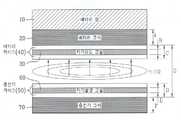
도 2는 본 발명에 따른 무접점 충전 구조를 나타낸 도면이다.2 is a view showing a contactless filling structure according to the present invention.
도 2를 참조하면, 하부에 도시된 충전기에서 발생된 전자기 유도에 의해 상부에 도시된 배터리에서 전류를 유도시켜 배터리 셀(10)에 충전시키는 구조이다.Referring to FIG. 2, a structure in which a current is induced in a battery illustrated in the upper portion and charged in the
도 2에서 무접점 충전을 위한 충전기는 충전기 케이스(50)와 충전기 코어(charger core)(70)가 계층을 이루어 구성된다. 그리고 충전기 케이스(50)는 외곽 케이스이며, 전자기 발생을 위한 자기발생 코일(60)을 내재한다. 또한 충전기는 자기발생 코일(60)에 전류를 공급하는 전원공급회로(미도시)를 더 포함하여 구성된다.In FIG. 2, the charger for contactless charging is composed of a
상기 충전기에서는 상기 충전기 코어(70)가 자기발생 코일(60)에 공급된 전류에 의해 전자기를 발생시킨다.In the charger, the
상기 자기발생 코일(60)을 내재하는 형상의 충전기 케이스(50)를 제작하는데는 다음의 방식들을 사용한다.The following methods are used to fabricate the
1. 자기발생 코일(60)을 삽입시켜 충전기 케이스(50)를 사출하는 공정으로 제작1. Production process by injecting the
2. 충전기 케이스(50)의 외부면과 내부면 사이에 자기발생 코일(60)을 내재시킬 공간을 형성시키는 제1공정, 그 형성된 공간에 자기발생 코일(60)을 안착시키는 제2공정, 자기발생 코일(60)이 안착된 후에 제1공정에서 형성된 공간을 충전제로 채우는 제3공정으로 제작2. The first step of forming a space for embedding the
3. 충전기 케이스(50)의 내부면에 자기발생 코일(60)을 내재시킬 홈을 형성하는 제1공정, 그 형성된 홈에 자기발생 코일(60)을 내장시키는 제2공정, 자기발생 코일(60)이 홈에 안착된 후에 제1공정에서 형성된 홈을 충전제로 채우는 제3공정으로 제작3. The first step of forming a groove for embedding the self-generating
한편 상기한 충전기 케이스(50)를 제작할 때, 자기발생 코일(60)의 양끝단은 충전기 케이스(50)에 내재시키지 않는다. 즉, 충전기 케이스(50)에 자기발생 코일(60)을 내재시킬 때, 자기발생 코일(60)의 양끝단들을 충전기 케이스(50)의 내부로 노출시킨다. 특히, 상기 노출된 양끝단은 전원공급회로(미도시)에 연결된다.On the other hand, when manufacturing the
또한 도 2에서 무접점 충전을 위한 배터리는 배터리 셀(10)과 배터리 코어(battery core)(20)와 배터리 케이스(40)가 계층을 이루어 구성된다. 그리고 배터리 케이스(40)는 외곽 케이스이며, 충전전류의 유도를 위한 자기유도 코일(30)을 내재한다.In addition, in FIG. 2, the battery for contactless charging is composed of a
상기 배터리 코어는 충전기에서 발생된 전자기에 의해 자기유도 코일(30)로 충전전류를 유도시킨다. 그러면 그 충전전류가 배터리 셀(10)에 충전된다.The battery core induces a charging current to the
상기 자기유도 코일(30)을 내재하는 형상의 배터리 케이스(40)를 제작하는데는 다음의 방식들을 사용한다.The following methods are used to fabricate the
1. 자기유도 코일(30)을 삽입시켜 배터리 케이스(40)를 사출하는 공정으로 제작1. Insert the
2. 배터리 케이스(40)의 외부면과 내부면 사이에 자기유도 코일(30)을 내재시킬 공간을 형성시키는 제1공정, 그 형성된 공간에 자기유도 코일(30)을 안착시키는 제2공정, 자기유도 코일(30)이 안착된 후에 제1공정에서 형성된 공간을 충전제로 채우는 제3공정으로 제작2. The first step of forming a space for embedding the
3. 배터리 케이스(40)의 내부면에 자기유도 코일(30)을 내재시킬 홈을 형성하는 제1공정, 그 형성된 홈에 자기유도 코일(30)을 내장시키는 제2공정, 자기유도 코일(30)이 홈에 안착된 후에 제1공정에서 형성된 홈을 충전제로 채우는 제3공정으로 제작3. The first step of forming a groove for embedding the
한편 상기한 배터리 케이스(40)를 제작할 때, 자기유도 코일(30)의 양끝단은 배터리 케이스(40)에 내재시키지 않는다. 즉, 배터리 케이스(40)에 자기유도 코일(30)을 내재시킬 때, 자기유도 코일(30)의 양끝단들을 배터리 케이스(40)의 내부로 노출시킨다. 특히, 상기 노출된 양끝단은 배터리 셀(10)에 연결된다. 보다 상세하게는, 배터리 셀(10)은 충전시 동작하는 충전회로를 구비하며, 상기 노출된 양끝단은 그 충전회로에 연결된다.On the other hand, when manufacturing the
본 발명에서는 전술된 바와 같이 자기발생 코일(60)을 충전기 케이스(50)에 내재시킴으로써, 충전기의 내부 공간 중에서 자기발생 코일(60)을 장착하기 위한 공간이 요구되지 않는다.In the present invention, the
또한 자기유도 코일(30)을 배터리 케이스(40)에 내재시킴으로써, 배터리의 내부 공간 중에서 자기유도 코일(30)을 장착하기 위한 공간이 요구되지 않는다.In addition, by incorporating the
따라서 충전기 코어(70)와 배터리 코어(20) 간의 거리인 공극(G)이 "자기발생 코일의 장착에 요구되는 충전기의 내부 공간 + 자기유도 코일의 장착에 요구되는 배터리의 내부 공간" 만큼 줄어든다.Therefore, the gap G, which is the distance between the
참고로, 본 발명에서 자기발생 코일(60)을 내재한 상태의 충전기 케이스(50)의 두께는 충전기 케이스(50)로써 요구되는 최소 두께를 만족시킨다. 또한 본 발명에서 자기유도 코일(30)을 내재한 상태의 배터리 케이스(40)의 두께는 배터리 케이스(40)로써 요구되는 최소 두께를 만족시킨다. 다시 말하자면, 자기발생 코일(60)을 내재시키기 위한 충전기 케이스(50)의 두께 증가는 없으며, 자기유도 코일(30)을 내재시키기 위한 배터리 케이스(40)의 두께 증가도 없다.For reference, in the present invention, the thickness of the
한편 자기유도 코일(30)을 내재한 배터리 케이스(40)와 자기발생 코일(60)을 내재한 충전기 케이스(50)가 서로 근접할 때 충전이 실시된다. 보다 상세하게, 자기유도 코일(30)이 내재된 배터리 케이스(40)의 외부면과 자기발생 코일(60)이 내재된 충전기 케이스(50)의 외부면이 근접할 때 충전이 실시된다.Meanwhile, charging is performed when the
배터리 케이스(40)와 충전기 케이스(50)가 서로 근접했을 때, 충전기의 자기발생 코일(60)로 흐르는 전류에 의해 충전기 코어(70)에 유도된 전자기가 충전기 케이스(50)를 통과하고 또한 배터리 케이스(40)를 통과하여 배터리 코어(20)에 전달된다.When the
그러면 배터리 코어(20)가 전달된 전자기에 의해 충전전류를 자기유도 코일(30)로 유도시킨다. 즉, 배터리 코어(20)로 전달된 전자기에 의해 자기유도 코일(30)에 충전전류가 발생된다. 그 충전전류는 배터리 셀(10)에 충전된다.Then, the
결국 본 발명에서는 따라서, 충전기에서 배터리로 충전 시에 공극(G)을 최소화하여 충전효율을 극대화시킨다.As a result, the present invention thus maximizes charging efficiency by minimizing voids (G) when charging from a charger to a battery.
도 3은 본 발명의 일 실시 예에 따른 무접점 충전을 위한 배터리 케이스 형상과 일측 단면을 나타낸 도면으로, 이동통신단말기에 결합되어 그 이동통신단말기 본체로 전원을 공급하는 배터리 케이스의 형성을 나타낸 것이다.3 is a view showing a battery case shape and one side cross-sectional view for contactless charging according to an embodiment of the present invention, showing the formation of a battery case coupled to a mobile communication terminal and supplying power to the mobile communication terminal body. .
도 3에서와 같이, 본 발명에서는 자기유도 코일을 배터리 케이스의 외곽면으로 노출시키지 않는다. 그리고 일측 단면에 나타낸 것처럼, 자기유도 코일을 배터리 케이스의 내부에 내재시킨다.As shown in FIG. 3, the magnetic induction coil is not exposed to the outer surface of the battery case. And, as shown in one cross section, a magnetic induction coil is embedded in the battery case.
도 4는 본 발명에 따른 무접점 충전기와 배터리의 일 예를 나타낸 단면도로써, 도 2에 도시된 무접점 충전 구조를 이용한 가장 일반적인 예를 나타낸 것이다.4 is a cross-sectional view showing an example of a contactless charger and a battery according to the present invention, showing a most general example using the contactless charging structure shown in FIG.
도 4에서 배터리 케이스(40)의 일면(도 4에서는 하면)에 자기유도 코일(30)을 내재하고, 충전기 케이스(50)의 일면(도 4에서는 상면)에 자기발생 코일(60)을 내재한다. 그리고 상기한 두 일면들이 근접할 때 무접점 충전이 실시된다.In FIG. 4, the
상기 도 4와 같이 충전기와 배터리를 형성하는 경우에는, 충전기 케이스에 자기발생 코일(60)을 내재시키는 면적을 배터리 케이스에 자기유도 코일(30)을 내 재시키는 면적보다 넓게 형성한다. 그리하여 배터리가 충전기 상면의 어느 위치에 놓이더라도 무접점 충전이 용이하게 실시되도록 한다.In the case of forming the charger and the battery as shown in FIG. 4, the area in which the
상기한 도 4의 예에서 충전기 케이스에 대해 배터리의 충전 위치를 자유롭게 보장하는 것과 달리 배터리가 정해진 위치에서 충전기에 근접하도록, 다음의 도 5는 자기발생 코일(60)에 내재된 충전기 케이스의 일면(도 5에서는 상면)에 요(凹)부를 형성한다.In the example of FIG. 4 described above, in order to allow the battery to approach the charger at a predetermined position, as opposed to freely guaranteeing the charging position of the battery with respect to the charger case, FIG. In Fig. 5, a concave portion is formed on the upper surface).
도 5는 본 발명의 일 실시 예에 따른 무접점 충전기와 배터리의 근접시 형상을 나타낸 도면이다.5 is a view showing a shape in proximity of a contactless charger and a battery according to an embodiment of the present invention.
도 5에서 요부는 자기발생 코일(60)이 내재된 충전기 케이스(50)의 외부면에 형성되며, 그 요부에 배터리가 일정 깊이만큼 묻히도록 형성된다.In FIG. 5, the recess is formed on the outer surface of the
그러면, 자기유도 코일(30)이 내재된 배터리 케이스(40)의 외부면이 충전기 케이스(50)에 형성된 요부의 바닥면에 접촉된다.Then, the outer surface of the
그리고 요부의 바닥면은 배터리 케이스(40)에서 자기유도 코일(30)이 내재된 외부면의 형상과 동일하도록 형성된다.And the bottom surface of the recess is formed to be the same as the shape of the outer surface in which the
상기한 본 발명에 따른 무접점 충전 장치는 이동통신단말기에 적용하는 것이 보다 바람직하다. 즉, 전술된 배터리는 이동통신단말기에 결합되어 이동통신단말기의 전원으로 동작한다. 그리고 그 배터리는 전술된 충전기를 통해 무접점 충전된다.The contactless charging device according to the present invention is more preferably applied to a mobile communication terminal. That is, the above-described battery is coupled to the mobile communication terminal to operate as a power source of the mobile communication terminal. The battery is then contactlessly charged through the charger described above.
이상 설명한 내용을 통해 당업자라면 본 발명의 기술 사상을 일탈하지 아니하는 범위에서 다양한 변경 및 수정 가능함을 알 수 있을 것이다.Those skilled in the art will appreciate that various changes and modifications can be made without departing from the spirit of the present invention.
따라서, 본 발명의 기술적 범위는 실시 예에 기재된 내용으로 한정되는 것이 아니라 특허 청구의 범위에 의하여 정해져야 한다.Therefore, the technical scope of the present invention should not be limited to the contents described in the embodiments, but should be defined by the claims.
이상에서 설명된 본 발명에 따르면, 충전기의 자기발생 코일을 충전기 외곽 케이스에 삽입시켜 형성하고 배터리의 자기유도 코일을 배터리 외곽 케이스에 삽입시켜 형성함으로써, 배터리 코어와 충전기 코어 사이의 공극이 최소화된다. 그에 따라 무접점 충전의 충전효율을 극대화시킨다. 또한 에너지 손실을 최소화시킴으로써 열 발생을 최소화시킨다.According to the present invention described above, by forming the magnetic generating coil of the charger in the charger outer case and formed by inserting the magnetic induction coil of the battery in the battery outer case, the gap between the battery core and the charger core is minimized. This maximizes the charging efficiency of contactless charging. It also minimizes heat dissipation by minimizing energy losses.
Claims (15)
Translated fromKoreanPriority Applications (1)
| Application Number | Priority Date | Filing Date | Title |
|---|---|---|---|
| KR1020050083656AKR100698219B1 (en) | 2005-09-08 | 2005-09-08 | Contactless charging device |
Applications Claiming Priority (1)
| Application Number | Priority Date | Filing Date | Title |
|---|---|---|---|
| KR1020050083656AKR100698219B1 (en) | 2005-09-08 | 2005-09-08 | Contactless charging device |
Publications (2)
| Publication Number | Publication Date |
|---|---|
| KR20070028896A KR20070028896A (en) | 2007-03-13 |
| KR100698219B1true KR100698219B1 (en) | 2007-03-22 |
Family
ID=38101384
Family Applications (1)
| Application Number | Title | Priority Date | Filing Date |
|---|---|---|---|
| KR1020050083656AExpired - Fee RelatedKR100698219B1 (en) | 2005-09-08 | 2005-09-08 | Contactless charging device |
Country Status (1)
| Country | Link |
|---|---|
| KR (1) | KR100698219B1 (en) |
Cited By (1)
| Publication number | Priority date | Publication date | Assignee | Title |
|---|---|---|---|---|
| KR101179398B1 (en) | 2011-04-27 | 2012-09-04 | 삼성전기주식회사 | Contactless power transmission device and electronic device having the same |
Families Citing this family (5)
| Publication number | Priority date | Publication date | Assignee | Title |
|---|---|---|---|---|
| EP1973008B1 (en) | 2007-03-23 | 2018-10-31 | HP Printing Korea Co., Ltd. | Image Forming Apparatus comprising a driving system for a plurality of photosensitive bodies |
| KR101041150B1 (en)* | 2009-01-30 | 2011-06-13 | 황인태 | Mobile phone solid state charging device |
| KR101782083B1 (en) | 2010-09-08 | 2017-09-27 | 삼성전자주식회사 | Roof type charging apparatus using resonant power transmission |
| KR102015703B1 (en) | 2017-10-27 | 2019-08-28 | 지이 하이브리드 테크놀로지스, 엘엘씨 | Non-contact power transmission syatem with overheat protection and method thereof |
| KR102069441B1 (en) | 2018-08-07 | 2020-01-22 | 지이 하이브리드 테크놀로지스, 엘엘씨 | Non-contact power transmission syatem with overheat protection and method thereof |
Citations (1)
| Publication number | Priority date | Publication date | Assignee | Title |
|---|---|---|---|---|
| KR950030433A (en)* | 1994-04-29 | 1995-11-24 | 완다 케이.덴슨-로우 | Inductive charging device |
- 2005
- 2005-09-08KRKR1020050083656Apatent/KR100698219B1/ennot_activeExpired - Fee Related
Patent Citations (1)
| Publication number | Priority date | Publication date | Assignee | Title |
|---|---|---|---|---|
| KR950030433A (en)* | 1994-04-29 | 1995-11-24 | 완다 케이.덴슨-로우 | Inductive charging device |
Non-Patent Citations (1)
| Title |
|---|
| 공개특허공보10-1995-0030433 |
Cited By (1)
| Publication number | Priority date | Publication date | Assignee | Title |
|---|---|---|---|---|
| KR101179398B1 (en) | 2011-04-27 | 2012-09-04 | 삼성전기주식회사 | Contactless power transmission device and electronic device having the same |
Also Published As
| Publication number | Publication date |
|---|---|
| KR20070028896A (en) | 2007-03-13 |
Similar Documents
| Publication | Publication Date | Title |
|---|---|---|
| CN108780934B (en) | Battery module, battery pack including battery module, and vehicle including battery pack | |
| CN109155449B (en) | Method for manufacturing battery module | |
| EP2876983A2 (en) | Electronic device and method for assembling the same | |
| CN101771283B (en) | Charging system | |
| CN101841173B (en) | Charging system | |
| CN110050381B (en) | Battery module, battery pack including battery module, and vehicle including battery pack | |
| KR20130094845A (en) | Non-contact charging module and non-contact charger | |
| US20170256990A1 (en) | Receiver Coil Arrangements for Inductive Wireless Power Transfer for Portable Devices | |
| US20110017282A1 (en) | Energy transfer through coupling from photovoltaic modules | |
| CN204204611U (en) | Coil layout, energy electrically driven vehicles and charging station | |
| JP2010245323A (en) | Coil unit and electronic equipment | |
| JP2010193701A (en) | Noncontact charger | |
| US9318914B2 (en) | Wireless charging device | |
| JP2012010533A (en) | Power transmission system, and power supply device and portable apparatus therefor | |
| KR100698219B1 (en) | Contactless charging device | |
| JP5327095B2 (en) | Vibration generator | |
| US20150256022A1 (en) | Non-contact type power charging apparatus and non-contact type battery apparatus | |
| CN107180696B (en) | Electronic equipment with heat sink | |
| JP2012221572A (en) | Battery module and portable terminal | |
| KR20120014878A (en) | Coils for solid state chargers and winding tools for manufacturing these coils | |
| CN102545361A (en) | Portable charger | |
| WO2020224185A1 (en) | Wireless charging coil | |
| CN112737143B (en) | Wireless charging coil and charging equipment | |
| KR20160050445A (en) | Wireless power charging apparatus | |
| KR101578863B1 (en) | Coils for wireless power communication and method for reeling coils |
Legal Events
| Date | Code | Title | Description |
|---|---|---|---|
| A201 | Request for examination | ||
| PA0109 | Patent application | St.27 status event code:A-0-1-A10-A12-nap-PA0109 | |
| PA0201 | Request for examination | St.27 status event code:A-1-2-D10-D11-exm-PA0201 | |
| E902 | Notification of reason for refusal | ||
| PE0902 | Notice of grounds for rejection | St.27 status event code:A-1-2-D10-D21-exm-PE0902 | |
| P11-X000 | Amendment of application requested | St.27 status event code:A-2-2-P10-P11-nap-X000 | |
| P13-X000 | Application amended | St.27 status event code:A-2-2-P10-P13-nap-X000 | |
| E701 | Decision to grant or registration of patent right | ||
| PE0701 | Decision of registration | St.27 status event code:A-1-2-D10-D22-exm-PE0701 | |
| PG1501 | Laying open of application | St.27 status event code:A-1-1-Q10-Q12-nap-PG1501 | |
| GRNT | Written decision to grant | ||
| PR0701 | Registration of establishment | St.27 status event code:A-2-4-F10-F11-exm-PR0701 | |
| PR1002 | Payment of registration fee | St.27 status event code:A-2-2-U10-U11-oth-PR1002 Fee payment year number:1 | |
| PG1601 | Publication of registration | St.27 status event code:A-4-4-Q10-Q13-nap-PG1601 | |
| PN2301 | Change of applicant | St.27 status event code:A-5-5-R10-R13-asn-PN2301 St.27 status event code:A-5-5-R10-R11-asn-PN2301 | |
| R18-X000 | Changes to party contact information recorded | St.27 status event code:A-5-5-R10-R18-oth-X000 | |
| R18-X000 | Changes to party contact information recorded | St.27 status event code:A-5-5-R10-R18-oth-X000 | |
| PR1001 | Payment of annual fee | St.27 status event code:A-4-4-U10-U11-oth-PR1001 Fee payment year number:4 | |
| PR1001 | Payment of annual fee | St.27 status event code:A-4-4-U10-U11-oth-PR1001 Fee payment year number:5 | |
| PR1001 | Payment of annual fee | St.27 status event code:A-4-4-U10-U11-oth-PR1001 Fee payment year number:6 | |
| FPAY | Annual fee payment | Payment date:20130226 Year of fee payment:7 | |
| PR1001 | Payment of annual fee | St.27 status event code:A-4-4-U10-U11-oth-PR1001 Fee payment year number:7 | |
| FPAY | Annual fee payment | Payment date:20140224 Year of fee payment:8 | |
| PR1001 | Payment of annual fee | St.27 status event code:A-4-4-U10-U11-oth-PR1001 Fee payment year number:8 | |
| FPAY | Annual fee payment | Payment date:20150224 Year of fee payment:9 | |
| PR1001 | Payment of annual fee | St.27 status event code:A-4-4-U10-U11-oth-PR1001 Fee payment year number:9 | |
| PN2301 | Change of applicant | St.27 status event code:A-5-5-R10-R13-asn-PN2301 St.27 status event code:A-5-5-R10-R11-asn-PN2301 | |
| FPAY | Annual fee payment | Payment date:20160224 Year of fee payment:10 | |
| PR1001 | Payment of annual fee | St.27 status event code:A-4-4-U10-U11-oth-PR1001 Fee payment year number:10 | |
| P22-X000 | Classification modified | St.27 status event code:A-4-4-P10-P22-nap-X000 | |
| FPAY | Annual fee payment | Payment date:20170224 Year of fee payment:11 | |
| PR1001 | Payment of annual fee | St.27 status event code:A-4-4-U10-U11-oth-PR1001 Fee payment year number:11 | |
| LAPS | Lapse due to unpaid annual fee | ||
| PC1903 | Unpaid annual fee | St.27 status event code:A-4-4-U10-U13-oth-PC1903 Not in force date:20180316 Payment event data comment text:Termination Category : DEFAULT_OF_REGISTRATION_FEE | |
| P22-X000 | Classification modified | St.27 status event code:A-4-4-P10-P22-nap-X000 | |
| PC1903 | Unpaid annual fee | St.27 status event code:N-4-6-H10-H13-oth-PC1903 Ip right cessation event data comment text:Termination Category : DEFAULT_OF_REGISTRATION_FEE Not in force date:20180316 | |
| PN2301 | Change of applicant | St.27 status event code:A-5-5-R10-R13-asn-PN2301 St.27 status event code:A-5-5-R10-R11-asn-PN2301 |