KR100697741B1 - Battery system, regenerative battery system and automobile - Google Patents
Battery system, regenerative battery system and automobileDownload PDFInfo
- Publication number
- KR100697741B1 KR100697741B1KR1020050088475AKR20050088475AKR100697741B1KR 100697741 B1KR100697741 B1KR 100697741B1KR 1020050088475 AKR1020050088475 AKR 1020050088475AKR 20050088475 AKR20050088475 AKR 20050088475AKR 100697741 B1KR100697741 B1KR 100697741B1
- Authority
- KR
- South Korea
- Prior art keywords
- battery
- storage system
- negative electrode
- power storage
- unit cell
- Prior art date
- Legal status (The legal status is an assumption and is not a legal conclusion. Google has not performed a legal analysis and makes no representation as to the accuracy of the status listed.)
- Expired - Lifetime
Links
Images


Classifications
- H—ELECTRICITY
- H01—ELECTRIC ELEMENTS
- H01M—PROCESSES OR MEANS, e.g. BATTERIES, FOR THE DIRECT CONVERSION OF CHEMICAL ENERGY INTO ELECTRICAL ENERGY
- H01M10/00—Secondary cells; Manufacture thereof
- H01M10/42—Methods or arrangements for servicing or maintenance of secondary cells or secondary half-cells
- H01M10/4207—Methods or arrangements for servicing or maintenance of secondary cells or secondary half-cells for several batteries or cells simultaneously or sequentially
- B—PERFORMING OPERATIONS; TRANSPORTING
- B60—VEHICLES IN GENERAL
- B60L—PROPULSION OF ELECTRICALLY-PROPELLED VEHICLES; SUPPLYING ELECTRIC POWER FOR AUXILIARY EQUIPMENT OF ELECTRICALLY-PROPELLED VEHICLES; ELECTRODYNAMIC BRAKE SYSTEMS FOR VEHICLES IN GENERAL; MAGNETIC SUSPENSION OR LEVITATION FOR VEHICLES; MONITORING OPERATING VARIABLES OF ELECTRICALLY-PROPELLED VEHICLES; ELECTRIC SAFETY DEVICES FOR ELECTRICALLY-PROPELLED VEHICLES
- B60L50/00—Electric propulsion with power supplied within the vehicle
- B60L50/50—Electric propulsion with power supplied within the vehicle using propulsion power supplied by batteries or fuel cells
- B—PERFORMING OPERATIONS; TRANSPORTING
- B60—VEHICLES IN GENERAL
- B60L—PROPULSION OF ELECTRICALLY-PROPELLED VEHICLES; SUPPLYING ELECTRIC POWER FOR AUXILIARY EQUIPMENT OF ELECTRICALLY-PROPELLED VEHICLES; ELECTRODYNAMIC BRAKE SYSTEMS FOR VEHICLES IN GENERAL; MAGNETIC SUSPENSION OR LEVITATION FOR VEHICLES; MONITORING OPERATING VARIABLES OF ELECTRICALLY-PROPELLED VEHICLES; ELECTRIC SAFETY DEVICES FOR ELECTRICALLY-PROPELLED VEHICLES
- B60L3/00—Electric devices on electrically-propelled vehicles for safety purposes; Monitoring operating variables, e.g. speed, deceleration or energy consumption
- B60L3/0023—Detecting, eliminating, remedying or compensating for drive train abnormalities, e.g. failures within the drive train
- B60L3/0046—Detecting, eliminating, remedying or compensating for drive train abnormalities, e.g. failures within the drive train relating to electric energy storage systems, e.g. batteries or capacitors
- B—PERFORMING OPERATIONS; TRANSPORTING
- B60—VEHICLES IN GENERAL
- B60L—PROPULSION OF ELECTRICALLY-PROPELLED VEHICLES; SUPPLYING ELECTRIC POWER FOR AUXILIARY EQUIPMENT OF ELECTRICALLY-PROPELLED VEHICLES; ELECTRODYNAMIC BRAKE SYSTEMS FOR VEHICLES IN GENERAL; MAGNETIC SUSPENSION OR LEVITATION FOR VEHICLES; MONITORING OPERATING VARIABLES OF ELECTRICALLY-PROPELLED VEHICLES; ELECTRIC SAFETY DEVICES FOR ELECTRICALLY-PROPELLED VEHICLES
- B60L50/00—Electric propulsion with power supplied within the vehicle
- B60L50/10—Electric propulsion with power supplied within the vehicle using propulsion power supplied by engine-driven generators, e.g. generators driven by combustion engines
- B60L50/16—Electric propulsion with power supplied within the vehicle using propulsion power supplied by engine-driven generators, e.g. generators driven by combustion engines with provision for separate direct mechanical propulsion
- B—PERFORMING OPERATIONS; TRANSPORTING
- B60—VEHICLES IN GENERAL
- B60L—PROPULSION OF ELECTRICALLY-PROPELLED VEHICLES; SUPPLYING ELECTRIC POWER FOR AUXILIARY EQUIPMENT OF ELECTRICALLY-PROPELLED VEHICLES; ELECTRODYNAMIC BRAKE SYSTEMS FOR VEHICLES IN GENERAL; MAGNETIC SUSPENSION OR LEVITATION FOR VEHICLES; MONITORING OPERATING VARIABLES OF ELECTRICALLY-PROPELLED VEHICLES; ELECTRIC SAFETY DEVICES FOR ELECTRICALLY-PROPELLED VEHICLES
- B60L53/00—Methods of charging batteries, specially adapted for electric vehicles; Charging stations or on-board charging equipment therefor; Exchange of energy storage elements in electric vehicles
- B60L53/10—Methods of charging batteries, specially adapted for electric vehicles; Charging stations or on-board charging equipment therefor; Exchange of energy storage elements in electric vehicles characterised by the energy transfer between the charging station and the vehicle
- B60L53/11—DC charging controlled by the charging station, e.g. mode 4
- B—PERFORMING OPERATIONS; TRANSPORTING
- B60—VEHICLES IN GENERAL
- B60L—PROPULSION OF ELECTRICALLY-PROPELLED VEHICLES; SUPPLYING ELECTRIC POWER FOR AUXILIARY EQUIPMENT OF ELECTRICALLY-PROPELLED VEHICLES; ELECTRODYNAMIC BRAKE SYSTEMS FOR VEHICLES IN GENERAL; MAGNETIC SUSPENSION OR LEVITATION FOR VEHICLES; MONITORING OPERATING VARIABLES OF ELECTRICALLY-PROPELLED VEHICLES; ELECTRIC SAFETY DEVICES FOR ELECTRICALLY-PROPELLED VEHICLES
- B60L58/00—Methods or circuit arrangements for monitoring or controlling batteries or fuel cells, specially adapted for electric vehicles
- B60L58/10—Methods or circuit arrangements for monitoring or controlling batteries or fuel cells, specially adapted for electric vehicles for monitoring or controlling batteries
- B60L58/12—Methods or circuit arrangements for monitoring or controlling batteries or fuel cells, specially adapted for electric vehicles for monitoring or controlling batteries responding to state of charge [SoC]
- B60L58/13—Maintaining the SoC within a determined range
- B—PERFORMING OPERATIONS; TRANSPORTING
- B60—VEHICLES IN GENERAL
- B60L—PROPULSION OF ELECTRICALLY-PROPELLED VEHICLES; SUPPLYING ELECTRIC POWER FOR AUXILIARY EQUIPMENT OF ELECTRICALLY-PROPELLED VEHICLES; ELECTRODYNAMIC BRAKE SYSTEMS FOR VEHICLES IN GENERAL; MAGNETIC SUSPENSION OR LEVITATION FOR VEHICLES; MONITORING OPERATING VARIABLES OF ELECTRICALLY-PROPELLED VEHICLES; ELECTRIC SAFETY DEVICES FOR ELECTRICALLY-PROPELLED VEHICLES
- B60L58/00—Methods or circuit arrangements for monitoring or controlling batteries or fuel cells, specially adapted for electric vehicles
- B60L58/10—Methods or circuit arrangements for monitoring or controlling batteries or fuel cells, specially adapted for electric vehicles for monitoring or controlling batteries
- B60L58/18—Methods or circuit arrangements for monitoring or controlling batteries or fuel cells, specially adapted for electric vehicles for monitoring or controlling batteries of two or more battery modules
- B—PERFORMING OPERATIONS; TRANSPORTING
- B60—VEHICLES IN GENERAL
- B60L—PROPULSION OF ELECTRICALLY-PROPELLED VEHICLES; SUPPLYING ELECTRIC POWER FOR AUXILIARY EQUIPMENT OF ELECTRICALLY-PROPELLED VEHICLES; ELECTRODYNAMIC BRAKE SYSTEMS FOR VEHICLES IN GENERAL; MAGNETIC SUSPENSION OR LEVITATION FOR VEHICLES; MONITORING OPERATING VARIABLES OF ELECTRICALLY-PROPELLED VEHICLES; ELECTRIC SAFETY DEVICES FOR ELECTRICALLY-PROPELLED VEHICLES
- B60L58/00—Methods or circuit arrangements for monitoring or controlling batteries or fuel cells, specially adapted for electric vehicles
- B60L58/10—Methods or circuit arrangements for monitoring or controlling batteries or fuel cells, specially adapted for electric vehicles for monitoring or controlling batteries
- B60L58/24—Methods or circuit arrangements for monitoring or controlling batteries or fuel cells, specially adapted for electric vehicles for monitoring or controlling batteries for controlling the temperature of batteries
- B60L58/26—Methods or circuit arrangements for monitoring or controlling batteries or fuel cells, specially adapted for electric vehicles for monitoring or controlling batteries for controlling the temperature of batteries by cooling
- B—PERFORMING OPERATIONS; TRANSPORTING
- B60—VEHICLES IN GENERAL
- B60L—PROPULSION OF ELECTRICALLY-PROPELLED VEHICLES; SUPPLYING ELECTRIC POWER FOR AUXILIARY EQUIPMENT OF ELECTRICALLY-PROPELLED VEHICLES; ELECTRODYNAMIC BRAKE SYSTEMS FOR VEHICLES IN GENERAL; MAGNETIC SUSPENSION OR LEVITATION FOR VEHICLES; MONITORING OPERATING VARIABLES OF ELECTRICALLY-PROPELLED VEHICLES; ELECTRIC SAFETY DEVICES FOR ELECTRICALLY-PROPELLED VEHICLES
- B60L7/00—Electrodynamic brake systems for vehicles in general
- B60L7/10—Dynamic electric regenerative braking
- B60L7/14—Dynamic electric regenerative braking for vehicles propelled by AC motors
- H—ELECTRICITY
- H01—ELECTRIC ELEMENTS
- H01M—PROCESSES OR MEANS, e.g. BATTERIES, FOR THE DIRECT CONVERSION OF CHEMICAL ENERGY INTO ELECTRICAL ENERGY
- H01M10/00—Secondary cells; Manufacture thereof
- H01M10/05—Accumulators with non-aqueous electrolyte
- H01M10/052—Li-accumulators
- H—ELECTRICITY
- H01—ELECTRIC ELEMENTS
- H01M—PROCESSES OR MEANS, e.g. BATTERIES, FOR THE DIRECT CONVERSION OF CHEMICAL ENERGY INTO ELECTRICAL ENERGY
- H01M10/00—Secondary cells; Manufacture thereof
- H01M10/42—Methods or arrangements for servicing or maintenance of secondary cells or secondary half-cells
- H01M10/44—Methods for charging or discharging
- H—ELECTRICITY
- H01—ELECTRIC ELEMENTS
- H01M—PROCESSES OR MEANS, e.g. BATTERIES, FOR THE DIRECT CONVERSION OF CHEMICAL ENERGY INTO ELECTRICAL ENERGY
- H01M10/00—Secondary cells; Manufacture thereof
- H01M10/60—Heating or cooling; Temperature control
- H01M10/61—Types of temperature control
- H01M10/613—Cooling or keeping cold
- H—ELECTRICITY
- H01—ELECTRIC ELEMENTS
- H01M—PROCESSES OR MEANS, e.g. BATTERIES, FOR THE DIRECT CONVERSION OF CHEMICAL ENERGY INTO ELECTRICAL ENERGY
- H01M10/00—Secondary cells; Manufacture thereof
- H01M10/60—Heating or cooling; Temperature control
- H01M10/62—Heating or cooling; Temperature control specially adapted for specific applications
- H01M10/625—Vehicles
- H—ELECTRICITY
- H01—ELECTRIC ELEMENTS
- H01M—PROCESSES OR MEANS, e.g. BATTERIES, FOR THE DIRECT CONVERSION OF CHEMICAL ENERGY INTO ELECTRICAL ENERGY
- H01M10/00—Secondary cells; Manufacture thereof
- H01M10/60—Heating or cooling; Temperature control
- H01M10/62—Heating or cooling; Temperature control specially adapted for specific applications
- H01M10/627—Stationary installations, e.g. power plant buffering or backup power supplies
- H—ELECTRICITY
- H01—ELECTRIC ELEMENTS
- H01M—PROCESSES OR MEANS, e.g. BATTERIES, FOR THE DIRECT CONVERSION OF CHEMICAL ENERGY INTO ELECTRICAL ENERGY
- H01M10/00—Secondary cells; Manufacture thereof
- H01M10/60—Heating or cooling; Temperature control
- H01M10/65—Means for temperature control structurally associated with the cells
- H01M10/656—Means for temperature control structurally associated with the cells characterised by the type of heat-exchange fluid
- H01M10/6561—Gases
- H01M10/6563—Gases with forced flow, e.g. by blowers
- H—ELECTRICITY
- H01—ELECTRIC ELEMENTS
- H01M—PROCESSES OR MEANS, e.g. BATTERIES, FOR THE DIRECT CONVERSION OF CHEMICAL ENERGY INTO ELECTRICAL ENERGY
- H01M10/00—Secondary cells; Manufacture thereof
- H01M10/60—Heating or cooling; Temperature control
- H01M10/65—Means for temperature control structurally associated with the cells
- H01M10/657—Means for temperature control structurally associated with the cells by electric or electromagnetic means
- H—ELECTRICITY
- H01—ELECTRIC ELEMENTS
- H01M—PROCESSES OR MEANS, e.g. BATTERIES, FOR THE DIRECT CONVERSION OF CHEMICAL ENERGY INTO ELECTRICAL ENERGY
- H01M4/00—Electrodes
- H01M4/02—Electrodes composed of, or comprising, active material
- H01M4/13—Electrodes for accumulators with non-aqueous electrolyte, e.g. for lithium-accumulators; Processes of manufacture thereof
- H01M4/131—Electrodes based on mixed oxides or hydroxides, or on mixtures of oxides or hydroxides, e.g. LiCoOx
- H—ELECTRICITY
- H01—ELECTRIC ELEMENTS
- H01M—PROCESSES OR MEANS, e.g. BATTERIES, FOR THE DIRECT CONVERSION OF CHEMICAL ENERGY INTO ELECTRICAL ENERGY
- H01M4/00—Electrodes
- H01M4/02—Electrodes composed of, or comprising, active material
- H01M4/36—Selection of substances as active materials, active masses, active liquids
- H01M4/48—Selection of substances as active materials, active masses, active liquids of inorganic oxides or hydroxides
- H01M4/485—Selection of substances as active materials, active masses, active liquids of inorganic oxides or hydroxides of mixed oxides or hydroxides for inserting or intercalating light metals, e.g. LiTi2O4 or LiTi2OxFy
- H—ELECTRICITY
- H01—ELECTRIC ELEMENTS
- H01M—PROCESSES OR MEANS, e.g. BATTERIES, FOR THE DIRECT CONVERSION OF CHEMICAL ENERGY INTO ELECTRICAL ENERGY
- H01M4/00—Electrodes
- H01M4/02—Electrodes composed of, or comprising, active material
- H01M4/36—Selection of substances as active materials, active masses, active liquids
- H01M4/48—Selection of substances as active materials, active masses, active liquids of inorganic oxides or hydroxides
- H01M4/50—Selection of substances as active materials, active masses, active liquids of inorganic oxides or hydroxides of manganese
- H01M4/505—Selection of substances as active materials, active masses, active liquids of inorganic oxides or hydroxides of manganese of mixed oxides or hydroxides containing manganese for inserting or intercalating light metals, e.g. LiMn2O4 or LiMn2OxFy
- H—ELECTRICITY
- H01—ELECTRIC ELEMENTS
- H01M—PROCESSES OR MEANS, e.g. BATTERIES, FOR THE DIRECT CONVERSION OF CHEMICAL ENERGY INTO ELECTRICAL ENERGY
- H01M4/00—Electrodes
- H01M4/02—Electrodes composed of, or comprising, active material
- H01M4/36—Selection of substances as active materials, active masses, active liquids
- H01M4/48—Selection of substances as active materials, active masses, active liquids of inorganic oxides or hydroxides
- H01M4/52—Selection of substances as active materials, active masses, active liquids of inorganic oxides or hydroxides of nickel, cobalt or iron
- H01M4/525—Selection of substances as active materials, active masses, active liquids of inorganic oxides or hydroxides of nickel, cobalt or iron of mixed oxides or hydroxides containing iron, cobalt or nickel for inserting or intercalating light metals, e.g. LiNiO2, LiCoO2 or LiCoOxFy
- H—ELECTRICITY
- H01—ELECTRIC ELEMENTS
- H01M—PROCESSES OR MEANS, e.g. BATTERIES, FOR THE DIRECT CONVERSION OF CHEMICAL ENERGY INTO ELECTRICAL ENERGY
- H01M4/00—Electrodes
- H01M4/02—Electrodes composed of, or comprising, active material
- H01M4/36—Selection of substances as active materials, active masses, active liquids
- H01M4/58—Selection of substances as active materials, active masses, active liquids of inorganic compounds other than oxides or hydroxides, e.g. sulfides, selenides, tellurides, halogenides or LiCoFy; of polyanionic structures, e.g. phosphates, silicates or borates
- H01M4/5825—Oxygenated metallic salts or polyanionic structures, e.g. borates, phosphates, silicates, olivines
- B—PERFORMING OPERATIONS; TRANSPORTING
- B60—VEHICLES IN GENERAL
- B60L—PROPULSION OF ELECTRICALLY-PROPELLED VEHICLES; SUPPLYING ELECTRIC POWER FOR AUXILIARY EQUIPMENT OF ELECTRICALLY-PROPELLED VEHICLES; ELECTRODYNAMIC BRAKE SYSTEMS FOR VEHICLES IN GENERAL; MAGNETIC SUSPENSION OR LEVITATION FOR VEHICLES; MONITORING OPERATING VARIABLES OF ELECTRICALLY-PROPELLED VEHICLES; ELECTRIC SAFETY DEVICES FOR ELECTRICALLY-PROPELLED VEHICLES
- B60L2200/00—Type of vehicles
- B60L2200/26—Rail vehicles
- H—ELECTRICITY
- H01—ELECTRIC ELEMENTS
- H01M—PROCESSES OR MEANS, e.g. BATTERIES, FOR THE DIRECT CONVERSION OF CHEMICAL ENERGY INTO ELECTRICAL ENERGY
- H01M10/00—Secondary cells; Manufacture thereof
- H01M10/42—Methods or arrangements for servicing or maintenance of secondary cells or secondary half-cells
- H01M10/44—Methods for charging or discharging
- H01M10/448—End of discharge regulating measures
- H—ELECTRICITY
- H01—ELECTRIC ELEMENTS
- H01M—PROCESSES OR MEANS, e.g. BATTERIES, FOR THE DIRECT CONVERSION OF CHEMICAL ENERGY INTO ELECTRICAL ENERGY
- H01M4/00—Electrodes
- H01M4/02—Electrodes composed of, or comprising, active material
- H01M2004/021—Physical characteristics, e.g. porosity, surface area
- H—ELECTRICITY
- H01—ELECTRIC ELEMENTS
- H01M—PROCESSES OR MEANS, e.g. BATTERIES, FOR THE DIRECT CONVERSION OF CHEMICAL ENERGY INTO ELECTRICAL ENERGY
- H01M4/00—Electrodes
- H01M4/02—Electrodes composed of, or comprising, active material
- H01M4/64—Carriers or collectors
- H01M4/66—Selection of materials
- H01M4/661—Metal or alloys, e.g. alloy coatings
- Y—GENERAL TAGGING OF NEW TECHNOLOGICAL DEVELOPMENTS; GENERAL TAGGING OF CROSS-SECTIONAL TECHNOLOGIES SPANNING OVER SEVERAL SECTIONS OF THE IPC; TECHNICAL SUBJECTS COVERED BY FORMER USPC CROSS-REFERENCE ART COLLECTIONS [XRACs] AND DIGESTS
- Y02—TECHNOLOGIES OR APPLICATIONS FOR MITIGATION OR ADAPTATION AGAINST CLIMATE CHANGE
- Y02E—REDUCTION OF GREENHOUSE GAS [GHG] EMISSIONS, RELATED TO ENERGY GENERATION, TRANSMISSION OR DISTRIBUTION
- Y02E60/00—Enabling technologies; Technologies with a potential or indirect contribution to GHG emissions mitigation
- Y02E60/10—Energy storage using batteries
- Y—GENERAL TAGGING OF NEW TECHNOLOGICAL DEVELOPMENTS; GENERAL TAGGING OF CROSS-SECTIONAL TECHNOLOGIES SPANNING OVER SEVERAL SECTIONS OF THE IPC; TECHNICAL SUBJECTS COVERED BY FORMER USPC CROSS-REFERENCE ART COLLECTIONS [XRACs] AND DIGESTS
- Y02—TECHNOLOGIES OR APPLICATIONS FOR MITIGATION OR ADAPTATION AGAINST CLIMATE CHANGE
- Y02T—CLIMATE CHANGE MITIGATION TECHNOLOGIES RELATED TO TRANSPORTATION
- Y02T10/00—Road transport of goods or passengers
- Y02T10/60—Other road transportation technologies with climate change mitigation effect
- Y02T10/70—Energy storage systems for electromobility, e.g. batteries
- Y—GENERAL TAGGING OF NEW TECHNOLOGICAL DEVELOPMENTS; GENERAL TAGGING OF CROSS-SECTIONAL TECHNOLOGIES SPANNING OVER SEVERAL SECTIONS OF THE IPC; TECHNICAL SUBJECTS COVERED BY FORMER USPC CROSS-REFERENCE ART COLLECTIONS [XRACs] AND DIGESTS
- Y02—TECHNOLOGIES OR APPLICATIONS FOR MITIGATION OR ADAPTATION AGAINST CLIMATE CHANGE
- Y02T—CLIMATE CHANGE MITIGATION TECHNOLOGIES RELATED TO TRANSPORTATION
- Y02T10/00—Road transport of goods or passengers
- Y02T10/60—Other road transportation technologies with climate change mitigation effect
- Y02T10/7072—Electromobility specific charging systems or methods for batteries, ultracapacitors, supercapacitors or double-layer capacitors
- Y—GENERAL TAGGING OF NEW TECHNOLOGICAL DEVELOPMENTS; GENERAL TAGGING OF CROSS-SECTIONAL TECHNOLOGIES SPANNING OVER SEVERAL SECTIONS OF THE IPC; TECHNICAL SUBJECTS COVERED BY FORMER USPC CROSS-REFERENCE ART COLLECTIONS [XRACs] AND DIGESTS
- Y02—TECHNOLOGIES OR APPLICATIONS FOR MITIGATION OR ADAPTATION AGAINST CLIMATE CHANGE
- Y02T—CLIMATE CHANGE MITIGATION TECHNOLOGIES RELATED TO TRANSPORTATION
- Y02T90/00—Enabling technologies or technologies with a potential or indirect contribution to GHG emissions mitigation
- Y02T90/10—Technologies relating to charging of electric vehicles
- Y02T90/12—Electric charging stations
- Y—GENERAL TAGGING OF NEW TECHNOLOGICAL DEVELOPMENTS; GENERAL TAGGING OF CROSS-SECTIONAL TECHNOLOGIES SPANNING OVER SEVERAL SECTIONS OF THE IPC; TECHNICAL SUBJECTS COVERED BY FORMER USPC CROSS-REFERENCE ART COLLECTIONS [XRACs] AND DIGESTS
- Y02—TECHNOLOGIES OR APPLICATIONS FOR MITIGATION OR ADAPTATION AGAINST CLIMATE CHANGE
- Y02T—CLIMATE CHANGE MITIGATION TECHNOLOGIES RELATED TO TRANSPORTATION
- Y02T90/00—Enabling technologies or technologies with a potential or indirect contribution to GHG emissions mitigation
- Y02T90/10—Technologies relating to charging of electric vehicles
- Y02T90/14—Plug-in electric vehicles
Landscapes
- Engineering & Computer Science (AREA)
- Chemical & Material Sciences (AREA)
- Chemical Kinetics & Catalysis (AREA)
- Electrochemistry (AREA)
- General Chemical & Material Sciences (AREA)
- Manufacturing & Machinery (AREA)
- Power Engineering (AREA)
- Transportation (AREA)
- Mechanical Engineering (AREA)
- Inorganic Chemistry (AREA)
- Sustainable Development (AREA)
- Life Sciences & Earth Sciences (AREA)
- Sustainable Energy (AREA)
- Physics & Mathematics (AREA)
- Electromagnetism (AREA)
- Materials Engineering (AREA)
- Crystallography & Structural Chemistry (AREA)
- Secondary Cells (AREA)
- Battery Electrode And Active Subsutance (AREA)
- Cell Electrode Carriers And Collectors (AREA)
- Battery Mounting, Suspending (AREA)
Abstract
Translated fromKoreanDescription
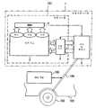
Translated fromKorean도1은 본 발명의 일실시 형태에 관한 회생 축전 시스템을 도시하는 모식도.1 is a schematic diagram showing a regenerative power storage system according to an embodiment of the present invention;
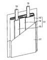
도2는 도1의 세트 전지를 구성하는 단위 셀을 도시하는 부분 절결 사시도.FIG. 2 is a partially cut-away perspective view showing a unit cell constituting the set battery of FIG. 1; FIG.
도3은 도1의 회생 축전 시스템의 동작을 나타내는 흐름도.3 is a flowchart showing the operation of the regenerative power storage system of FIG.
도4는 도1의 세트 전지와 배터리 제어 유닛과의 상세한 관계를 나타내는 블럭도.FIG. 4 is a block diagram showing a detailed relationship between the set battery and the battery control unit of FIG. 1; FIG.
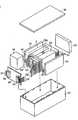
도5는 제1 실시 형태 및 제2 실시 형태에 관한 축전지 시스템으로 사용되는 전지 팩의 분해 사시도.5 is an exploded perspective view of a battery pack used as a battery system according to the first embodiment and the second embodiment;
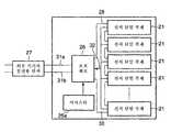
도6은 도5의 전지 팩의 전기 회로를 나타내는 블럭도.6 is a block diagram showing an electric circuit of the battery pack of Fig. 5;
도7은 도5의 전지 팩에 사용하는 편평형 비수 전해질 이차 전지의 다른 예를 모식적으로 나타내는 부분 절결 사시도.7 is a partially cutaway perspective view that schematically shows another example of a flat non-aqueous electrolyte secondary battery used in the battery pack of FIG.
도8은 도7의 A부의 확대 단면도.8 is an enlarged sectional view of part A of Fig.
<도면의 주요 부분에 대한 부호의 설명>Description of the Related Art
1 : 회생 축전 시스템1: Regenerative power storage system
2 : 승압 기구2:
3 : 세트 전지3: Set battery
4 : 배터리 제어 유닛4: Battery control unit
5 : 모터와 발전기5: Motor and generator
6 : 온도 센서6: Temperature sensor
7 : 전압계7: Voltmeter
8 : 전류계8: Ammeter
9a : 충방전 제어 회로9a: charge / discharge control circuit
9b : 충전 차단 회로9b: charge cutoff circuit
9c : 방전 차단 회로9c: discharge cutoff circuit
11 : 전극군11: Electrode group
12 : 양극12: anode
12a : 양극 집전체12a: anode current collector
12b : 양극 활물질 함유층12b: cathode active material-containing layer
13 : 음극13: cathode
13a : 음극 집전체13a: cathode collector
13b : 음극 활물질 함유층13b: anode active material-containing layer
14 : 세퍼레이터14: Separator
15 : 양극 단자15: positive terminal
16 : 음극 단자16: negative terminal
17 : 용기17: container
18 : 적층 전극군18: laminated electrode group
21 : 단위 셀21: Unit cell
23 : 점착 테이프23: Adhesive tape
24 : 프린트 배선 기판24: printed wiring board
28 : 양극측 배선28: anode side wiring
29 : 양극측 커넥터29: Positive electrode side connector
30 : 음극측 배선30: Cathode side wiring
31 : 음극측 커넥터31: Cathode connector
33 : 보호 시트33: Protective sheet
34 : 보호 블럭34: Protective block
35 : 수납 용기35: Storage container
36 : 덮개36: Cover
101 : 축전 시스템101: Power storage system
102 : 자동차102: Cars
[문헌 1] 일본 특허 공개 제2003-219510호 공보[Patent Document 1] Japanese Unexamined Patent Publication No. 2003-219510
본 발명은 에너지 효율의 향상을 목적으로 한 자동차, 이륜차, 전차, 엘리베이터, 풍력 발전 등에 사용되는 회생용 축전 시스템에 적합한 축전지 시스템에 관 한 것이다.The present invention relates to a battery system suitable for a regenerative power storage system for use in automobiles, motorcycles, electric vehicles, elevators, wind turbines, etc. for the purpose of improving energy efficiency.
최근, 에너지의 유효 이용, 환경 대책으로부터 회생 에너지를 유효 활용하기 위해, 전지를 탑재한 하이브리드 자동차, 이륜차, 전차, 엘리베이터, 풍력 발전 등이 검토되고, 일부는 실용화되어 있다. 지금까지 실용화되고, 탑재되어 있는 전지는 납축 전지나 니켈 수소 전지이다.Recently, a hybrid vehicle, a motorcycle, a trolley, an elevator, a wind power generation and the like equipped with a battery have been studied and some of them have been put into practical use in order to effectively utilize the regenerative energy from the effective utilization of energy and environmental measures. Batteries that have been put to practical use so far include lead-acid batteries and nickel-metal hydride batteries.
그러나, 예를 들어 하이브리드 자동차에 사용되고 있는 니켈 수소 전지에서는 고출력시 혹은 급속 충전(회생)시에 급격히 발열하고, 게다가 열 열화가 매우 커지는 문제점이 있다.However, for example, in a nickel-metal hydride battery used in a hybrid vehicle, there is a problem that heat is rapidly generated at the time of high output or rapid charging (regeneration), and further, thermal deterioration becomes very large.
이와 같은 이유로, 니켈 수소 전지보다도 열 열화가 작고, 또한 세트 전지의 경량화 및 박형화가 가능한 리튬 이온 전지의 탑재의 검토가 진행되고 있지만, 여름철 등의 고온 환경에 있어서 전지가 팽창하여 변형되게 되는 문제점이 있다.For this reason, studies have been made on the mounting of a lithium ion battery which is smaller in thermal deterioration than a nickel-metal hydride battery and capable of making a set battery lighter and thinner. However, there is a problem that the battery is expanded and deformed in a high- have.
특허문헌 1에는, 이차 전지의 온도가 소정의 온도 이상인 경우, 미리 정해진 온도에 따라서 변화되는 충방전 전력 상한치를 넘지 않도록, 충방전 전력을 제어하는 충방전 전력 제한 수단을 구비한 충방전 제어 장치가 기재되어 있다.
[특허문헌 1] 일본 특허 공개 제2003-219510호 공보[Patent Document 1] Japanese Unexamined Patent Publication No. 2003-219510
본 발명은 고온 환경하에서의 회생 충전과 같은 고온 환경하에서의 급속 충전시의 전지 팽창이 저감된 회생용 축전 시스템 및 축전 시스템과, 상기 회생용 축전 시스템 또는 전기 축전 시스템을 구비한 자동차를 제공하는 것을 목적으로 한다.An object of the present invention is to provide a regenerative power storage system and a power storage system in which battery expansion during rapid charging under a high temperature environment such as regenerative charging under a high temperature environment is reduced and an automobile provided with the regenerative power storage system or the electric storage system do.
본 발명에 관한 회생용 축전 시스템은 리튬티탄 복합 산화물을 함유하는 음극층 및 상기 음극층이 담지되는 집전체를 포함하는 음극을 구비한 비수 전해질 이차 전지를 단위 셀로 하고, 회생 전력에 의해 충전이 이루어지는 세트 전지와,A regenerative power storage system according to the present invention comprises a nonaqueous electrolyte secondary battery having a negative electrode including a negative electrode layer containing a lithium titanium composite oxide and a negative electrode containing a negative electrode layer as a unit cell, A set battery,
상기 세트 전지의 온도가 45 ℃ 이상, 90 ℃ 이하일 때에 상기 단위 셀의 최대 충전 종지 전압 V1(V)을 하기 [수학식 1]의 범위 내로 제어하는 충전 제어 수단을 구비하는 것을 특징으로 한다.And charging control means for controlling the maximum charging end voltage V1 (V) of the unit cell within a range of the following formula (1) when the temperature of the set battery is 45 ° C or more and 90 ° C or less.
단, V0는 상기 세트 전지를 25 ℃에서 만충전하였을 때의 상기 단위 셀의 최대 충전 종지 전압(V)을 나타낸다.V0 represents the maximum charging end voltage (V) of the unit cell when the set battery is fully charged at 25 ° C.
본 발명에 관한 축전 시스템은 리튬티탄 복합 산화물을 함유하는 음극층 및 상기 음극층이 담지되는 집전체를 포함하는 음극과 양극과 비수 전해질을 구비한 비수 전해질 이차 전지로 이루어지는 단위 셀을 구비하는 세트 전지와,A power storage system according to the present invention includes a set cell including a negative electrode including a lithium-titanium composite oxide, a negative electrode including a current collector on which the negative electrode is supported, and a nonaqueous electrolyte secondary battery having a positive electrode and a non- Wow,
상기 세트 전지의 온도를 측정하기 위한 온도 센서와,A temperature sensor for measuring the temperature of the set battery,
상기 단위 셀의 전압을 계측하기 위한 전압계와,A voltmeter for measuring a voltage of the unit cell;
상기 세트 전지의 온도가 45 ℃ 이상, 90 ℃ 이하일 때에 상기 단위 셀의 최대 충전 종지 전압 V1(V)을 하기 [수학식 1]의 범위 내로 제어하는 충전 제어 수단을 구비하는 것을 특징으로 한다.And charging control means for controlling the maximum charging end voltage V1 (V) of the unit cell within a range of the following formula (1) when the temperature of the set battery is 45 ° C or more and 90 ° C or less.
[수학식 1][Equation 1]
0.85 × V0 ≤ V1 ≤ 0.96 × V00.85 x V0 ? V1 ? 0.96 x V0
단, V0는 상기 세트 전지를 25 ℃에서 만충전하였을 때의 상기 단위 셀의 최대 충전 종지 전압(V)을 나타낸다.V0 represents the maximum charging end voltage (V) of the unit cell when the set battery is fully charged at 25 ° C.
본 발명에 관한 자동차는 상기 회생용 축전 시스템 또는 전기 축전 시스템을 구비하는 것을 특징으로 하는 것이다.The automobile according to the present invention is characterized by including the above-described regenerative power storage system or the electric storage system.
상기 회생용 축전 시스템 및 전기 축전 시스템에 있어서는, 상기 충전 제어 수단이 상기 세트 전지의 온도가 45 ℃ 이상, 90 ℃ 이하일 때에 상기 세트 전지의 충전 용량을 제어하면서, 상기 최대 충전 종지 전압 V1(V)을 상기 [수학식 1]의 범위 내로 제어하는 것이 바람직하다.In the above-described regenerative power storage system and electric power storage system, the charge control means is the maximum end-of-charge, while controlling the charge capacity of the set battery, the temperature of the set of cells when more than 45 ℃, 90 ℃ equal to or less than the voltage V1 (V ) Within the range of the above-mentioned expression (1).
또한, 본 발명에 따르면, 리튬티탄 복합 산화물을 함유하는 음극층 및 상기 음극층이 담지되는 집전체를 포함하는 음극을 구비한 비수 전해질 이차 전지를 단위 셀로 하고, 회생 전력에 의해 충전이 이루어지는 세트 전지와,According to the present invention, there is provided a nonaqueous electrolyte secondary battery comprising a nonaqueous electrolyte secondary battery having a negative electrode including a lithium-titanium composite oxide and a negative electrode including a current collector on which the negative electrode is supported, Wow,
상기 세트 전지의 온도가 45 ℃ 이상, 90 ℃ 이하일 때에 상기 단위 셀의 충전 종지 전압 V1(V)이 하기 [수학식 1]을 만족하도록 충전량을 제어하는 충전 제어 수단을 구비하는 것을 특징으로 하는 회생용 축전 시스템을 제공할 수 있다.And charging control means for controlling the charged amount so that the charging end voltage V1 (V) of the unit cell satisfies the following formula (1) when the temperature of the set battery is 45 ° C or more and 90 ° C or less It is possible to provide a regenerative power storage system.
[수학식 1][Equation 1]
0.85 × V0 ≤ V1 ≤ 0.96 × V00.85 x V0 ? V1 ? 0.96 x V0
단, V0는 상기 세트 전지를 25 ℃에서 만충전하였을 때의 상기 단위 셀의 충전 종지 전압(V)을 나타낸다.Note that V0 represents the end-of-charge voltage (V) of the unit cell when the set battery is fully charged at 25 ° C.
(제1 실시 형태)(First Embodiment)
본 발명자들은 음극 활물질에 리튬티탄 복합 산화물을 포함하는 음극을 구비한 비수 전해질 이차 전지의 세트 전지에 회생 충전을 실시할 때, 고온으로 충전 심도를 깊게 하면 세트 전지가 팽창하는 것은, 리튬티탄 복합 산화물의 리튬 흡장 전위가 비측으로 시프트하는 동시에, 비수 전해질 중의 비수용매의 환원 분해 전위가 귀측으로 시프트하여 쌍방의 전위차가 작아져 비수용매와 리튬티탄 복합 산화물과의 반응에 의해 가스가 발생했기 때문인 것을 구명하였다.The inventors of the present invention found that when a set battery of a non-aqueous electrolyte secondary battery having a negative electrode containing a lithium-titanium composite oxide in a negative electrode active material is regenerated charged, if the charge depth is increased at a high temperature, And that the reduction potential of the non-aqueous solvent in the non-aqueous electrolyte shifts to the ear side and the potential difference therebetween becomes small, and that the gas is generated by the reaction between the non-aqueous solvent and the lithium titanium composite oxide Respectively.
그리고, 세트 전지의 온도가 45 ℃ 이상, 90 ℃ 이하일 때에 단위 셀의 폐회로에서의 최대 충전 종지 전압 V1(V)이 하기 [수학식 1]을 만족하는 바와 같이 충전량을 제어함으로써, 회생용 축전 시스템에 있어서의 세트 전지의 팽창이 작아지는 것을 발견한 것이다.Then, when the temperature of the set battery is 45 ° C or more and 90 ° C or less, the charge amount is controlled so that the maximum charge end voltage V1 (V) at the closed circuit of the unit cell satisfies the following formula (1) And the expansion of the set battery in the system is reduced.
[수학식 1][Equation 1]
0.85 × V0 ≤ V1 ≤ 0.96 × V00.85 x V0 ? V1 ? 0.96 x V0
단, V0는 상기 세트 전지를 25 ℃에서 만충전하였을 때의 상기 단위 셀의 폐회로에서의 최대 충전 종지 전압(V)을 나타낸다. 여기서, 만충전 상태라 함은, 세트 전지의 정격 용량까지 충전하는 것을 의미한다. 세트 전지의 정격 용량이라 함은, 설계된 방전 용량의 0.2 C㎃에 상당하는 전류치로 방전한 방전 용량이다.V0 represents the maximum charging end voltage (V) at the closed circuit of the unit cell when the set battery is fully charged at 25 ° C. Here, the fully charged state means charging up to the rated capacity of the set battery. The rated capacity of the set battery is the discharge capacity discharged at a current value corresponding to 0.2 mA of the designed discharge capacity.
최대 충전 종지 전압 V1과 최대 충전 종지 전압 V0는 모두 세트 전지를 구성하는 모든 단위 셀 중에서 최대 충전 종지 전압을 나타내는 단위 셀의 전압치로 한다.Both the maximum charging end voltage V1 and the maximum charging end voltage V0 are voltage values of a unit cell indicating the maximum charging end voltage among all the unit cells constituting the set battery.
상기 세트 전지를 구성하는 단위 셀은 용량 및 임피던스에 분포를 가지므로, 세트 전지의 만충전시에 있어서 각 단위 셀의 충전 전압에 차를 생기게 한다. 따라서, 용량이 작거나 혹은 임피던스가 큰 단위 셀의 충전 전압은 최대 충전 종지 전압이 되기 쉽다. 이로 인해, 축전지 시스템의 수명 성능을 높게 유지하기 위해서는 단위 셀의 최대 충전 종지 전압으로 제어하는 것이 중요해진다.Since the unit cells constituting the set battery have a distribution in capacity and impedance, a difference occurs in the charging voltage of each unit cell in the full-charge display of the set battery. Therefore, the charging voltage of the unit cell having a small capacitance or a large impedance tends to become the maximum charging end voltage. For this reason, in order to maintain the lifetime performance of the battery system high, it is important to control to the maximum charging end voltage of the unit cell.
최대 충전 종지 전압 V1(V)이 0.96 × V0를 넘으면, 리튬티탄 복합 산화물의 리튬 흡장 전위와 비수용매의 환원 분해 전위와의 차가 작아지고, 다량의 가스가 발생하여 세트 전지가 팽창된다. 한편, 최대 충전 종지 전압 V1(V)을 0.85 × V0 미만으로 하면, 충전 용량이 부족해지므로 세트 전지의 출력 특성이 저하된다. 이상의 이유에 의해 최대 충전 종지 전압 V1(V)을 상기 [수학식 1]의 범위로 규정한다. 더욱 바람직한 범위는, 0.9 × V0 ≤ V1 ≤ 0.96 × V0이다.When the maximum end-of-charge voltage V1 (V) exceeds 0.96 x V0 , the difference between the lithium occlusion potential of the lithium-titanium composite oxide and the reduced decomposition potential of the non-aqueous solvent decreases and a large amount of gas is generated to swell the set battery. On the other hand, when the maximum charging end voltage V1 (V) is less than 0.85 x V0 , the charging capacity is insufficient and the output characteristics of the set battery are deteriorated. For the above reason, the maximum charging end voltage V1 (V) is defined by the range of the above-mentioned formula (1). A more preferable range is 0.9 x V0 ? V1 ? 0.96 x V0 .
음극 집전체로서 알루미늄박 또는 알루미늄 합금박을 사용함으로써, 음극의 방열성의 개선과 단위 셀 중 온도 분포의 균일성을 높일 수 있으므로, 단위 셀 내의 온도 변동과 단위 셀 사이의 온도 변동을 작게 할 수 있고, 세트 전지의 충방전 사이클 수명을 향상시킬 수 있다. 단위 셀의 정격 용량이 커지면, 열의 분포가 치 우치기 쉬워지므로, 이 경우에 음극 집전체에의 알루미늄박 또는 알루미늄 합금박의 사용이 보다 효과적이다.By using an aluminum foil or an aluminum alloy foil as the anode current collector, it is possible to improve the heat dissipation property of the cathode and the uniformity of the temperature distribution in the unit cell, so that the temperature fluctuation in the unit cell and the temperature fluctuation between the unit cells can be reduced , It is possible to improve the charge / discharge cycle life of the set battery. If the rated capacity of the unit cell is large, the distribution of the heat becomes liable to be high, and in this case, the use of aluminum foil or aluminum alloy foil on the negative electrode collector is more effective.
또한, 음극 집전체로서 평균 결정 입자 직경이 50 ㎛ 이하인 알루미늄박 혹은 평균 결정 입자 직경이 50 ㎛ 이하인 알루미늄 합금박을 사용함으로써 음극의 방열성 및 화학적 안정성이 향상되므로, 고온에서 회생 충전시의 가스 발생량을 보다 적게 할 수 있다.Further, by using an aluminum foil having an average crystal grain diameter of 50 m or less or an aluminum alloy foil having an average crystal grain diameter of 50 m or less as the negative electrode collector, heat dissipation property and chemical stability of the negative electrode are improved, Can be made less.
이하, 본 발명의 일실시 형태를 도면을 참조하여 설명한다.BEST MODE FOR CARRYING OUT THE INVENTION Hereinafter, one embodiment of the present invention will be described with reference to the drawings.
도1은 본 발명의 일실시 형태에 관한 회생 축전 시스템(1), 축전 시스템(101) 및 자동차(102)를 도시하는 모식도이고, 도2는 도1의 세트 전지를 구성하는 단위 셀을 나타내는 부분 절결 사시도이고, 도3은 도1의 회생 축전 시스템의 동작을 나타내는 흐름도이고, 도4는 도1의 세트 전지와 배터리 제어 유닛과의 상세한 관계를 나타내는 블럭도이다.1 is a schematic diagram showing a regenerative
이 회생 축전 시스템(1)은 축전 시스템(101) 및 모터 및 발전기(5)로 주로 구성되고, 모터 및 발전기(5)에는 자동차(102)의 차륜(103)이 차축(104) 등을 거쳐서 연접되어 있다. 또한, 자동차(102)의 차륜(103)을 구동하기 위해, 모터 및 발전기(5)의 모터 부분으로 구동해도 좋지만, 하이브리드형 자동차와 같이 내연 기관(105)을 병용하여 구동해도 좋다. 축전 시스템(101)은 승압 기구(2)와, 승압 기구(2)에 접속된 세트 전지(3)와 세트 전지(3)에 접속된 배터리 제어 유닛(BMU)(4)을 구비한다. 세트 전지(3)는 박형 비수 전해질 이차 전지를 단위 셀로 하고, 복수의 단위 셀을 직렬 혹은 병렬로 접속한 모듈을 구비하는 것이다. 박형 비수 전해질 이차 전지의 일예를 도2에 나타낸다. 전극군(11)은 양극(12) 및 음극(13)을 그 사이에 세퍼레이터(14)를 개재시켜 편평 형상이 되도록 소용돌이 형상으로 권취한 구조를 갖는다. 전극군(11)은 예를 들어 양극(12) 및 음극(13)을 그 사이에 세퍼레이터(14)를 개재시켜 편평 형상이 되도록 소용돌이 형상으로 권취한 후, 가열 프레스를 실시함으로써 제작된다. 전극군(11)에 있어서의 양극(12), 음극(13) 및 세퍼레이터(14)는 접착성을 갖는 고분자에 의해 일체화되어 있어도 좋다. 띠 형상의 양극 단자(15)는 양극(12)에 전기적으로 접속되어 있다. 한편, 띠 형상의 음극 단자(16)는 음극(13)에 전기적으로 접속되어 있다. 이 전극군(11)은 라미네이트 필름으로 된 용기(17) 내에 양극 단자(15)와 음극 단자(16)의 단부를 용기(17)로부터 돌출시킨 상태로 수납되어 있다. 또, 라미네이트 필름으로 된 용기(17)는 열밀봉에 의해 밀봉이 되어 있다.The regenerative
배터리 제어 유닛(BMU)(4)은 도4에 도시한 바와 같이 세트 전지(3)의 온도를 측정하기 위한 온도 센서(예를 들어 열전대, 서미스터 등)(6)와, 세트 전지 전압 및 단위 셀 전압을 계측하기 위한 전압계(7)와, 세트 전지의 전류를 계측하기 위한 전류계(8)와, 충방전 제어 회로(9a)와, 충전 차단 회로(9b)와, 방전 차단 회로(9c)를 구비하는 것이다.4, the battery control unit (BMU) 4 includes a temperature sensor (for example, a thermocouple, a thermistor, etc.) 6 for measuring the temperature of the set
충방전 제어 회로(9a)에는 온도 센서(6), 전압계(7) 및 전류계(8) 각각의 측정 결과가 입력된다. 이 입력 신호를 기초로, 충전 차단 회로(9b)나 방전 차단 회로(9c)에 신호가 입력되어 세트 전지(3)의 충방전을 제어할 수 있다. 구체적으로는, 충방전 제어 회로(9a)는 측정 결과를 기초로 하여 충전 상태(SOC)를 설정하고, 그 결과를 충전 차단 회로(9b) 및 방전 차단 회로(9c)에 송신한다. 충전 차단 회로(9b) 또는 방전 차단 회로(9c)는 설정된 SOC를 취하기 위해 필요한 충전 용량을 연산할 수 있다. 도1의 경우, 충전 차단 회로(9b)에서 연산이 행해진다. 연산 결과는 충방전 제어 회로(9a)에 송신된다. 세트 전지(3)의 충방전에 의해 충전 용량이 소정의 값에 이르면, 충방전 제어 회로(9a)로부터 충전 차단 회로(9b) 및 방전 차단 회로(9c)에 신호가 입력되어 충전과 방전이 정지되고, SOC를 소정치로 제어할 수 있다.The charge /
이와 같은 회생 축전 시스템(1)은 외부 부하로서의 자동차의 직류 모터 및 발전기(5)와 연결된다. 자동차로서는, 예를 들어 이륜 내지 사륜의 하이브리드 자동차나 전기 자동차 등을 들 수 있다. 직류 모터에 접속된 발전기는 회생 축전 시스템의 승압 기구(2)에 접속되어 있다. 승압 기구(2)는 세트 전지(3)에 회생 전력을 공급하는 충전기로서의 역할을 하고 있다. 한편, 직류 모터에는 회생 축전 시스템의 BMU(4)가 접속되어 있다. 이에 의해, 충방전 제어 회로(9a) 및 방전 차단 회로(9c)로부터의 신호에 따라서 세트 전지(3)로부터 직류 모터에의 출력을 제어할 수 있다.Such a regenerative
이 회생 축전 시스템(1)의 동작을 도3을 참조하여 설명한다.The operation of the regenerative
하이브리드 자동차 등의 직류 모터의 구동에 의해 발전기에서 발전된 전력은 승압 기구(2)로 승압시킨 후 세트 전지(3)에 공급된다. 세트 전지(3)가 충전(입력)되는 경우, 회생 축전 시스템(1)의 BMU(4)의 온도 센서(6)에 의해 세트 전지(3)의 온도를 모니터하고(S1), 그 결과를 수시 충방전 제어 회로(9a)에 송신한다. 충 방전 제어 회로(9a)에 있어서는, 세트 전지(3)의 온도가 45 ℃ 미만이면, 만충전 혹은 소정의 충전 상태(SOC)가 될 때까지 충전을 행하여 충전을 종료한다(S2). 또한, 세트 전지(3)의 온도가 90 ℃를 넘었으면, 충전 차단 회로(9b) 및 방전 차단 회로(9c)에 신호가 보내어져 충전(입력) 및 방전(출력)은 대기(정지)의 상태가 된다(S3). 이들 결과, 전지의 발열이 정지하여 전지 온도가 45 ℃ 미만까지 냉각된다. 세트 전지(3)는 30 ℃ 이하까지 냉각되는 것이 바람직하다.The electric power generated by the generator by the drive of the DC motor such as a hybrid vehicle is boosted to the boosting
한편, 세트 전지(3)의 온도가 45 ℃ 이상, 90 ℃ 이하인 경우(S4), BMU(4)로부터 세트 전지(3)에 충전(입력) 혹은 방전(출력) 개시의 신호가 보내진다. 이에 의해, 소정의 충전 상태(SOC)로 제어하면서, V1을 상기 [수학식 1]의 범위 내로 설정할 수 있다(S5). 소정의 충전 상태(SOC)는 만충전의 60 내지 90 %로 하는 것이 바람직하다.On the other hand, when the temperature of the set
BMU(4)에서는 세트 전지(3) 및 단위 셀의 전압 및 전류를 모니터하고 있다(S6). 충방전 제어 회로(9a)에 있어서는, 단위 셀의 폐회로에서의 최대 충전 종지 전압(V1)과 BMU(4)에 미리 입력되어 있는 최대 충전 종지 전압(V0)과의 비교를 행하여, 최대 충전 종지 전압(V1)이 전술한 [수학식 1]의 범위 내에 도달한 시점에서 충전 차단 회로(9a)에 신호를 출력하고(S7) 충전을 종료한다(S8).In the
상기 시스템에 따르면, 단위 셀의 최대 충전 종지 전압 V1을 전술한 [수학식 1]의 범위 내로 둘 수 있고, 또한 충전에 의한 세트 전지의 온도 상승이 억제되므로 충전에 의한 세트 전지의 팽창을 억제할 수 있다. 또한, 방전함으로써 충전 용 량을 제어하고 있으므로, 시스템을 복잡하게 하는 일 없이, 또한 확실하게 최대 충전 종지 전압 V1을 전술한 [수학식 1]의 범위 내로 유지할 수 있다.According to this system, the maximum charging end voltage V1 of the unit cell can be kept within the range of the above-mentioned formula (1), and the temperature rise of the set battery due to charging is suppressed, can do. In addition, since the charging capacity is controlled by discharging, the maximum charging end voltage V1 can be surely maintained within the range of the above-mentioned expression (1) without complicating the system.
또, 전술한 도1에 나타내는 회생용 축전 시스템에는 냉각팬은 구비되어 있지 않지만, 냉각팬 등을 도입하여 세트 전지를 냉각하는 것도 가능하다. 이 경우, 상기 세트 전지(3)의 온도가 45 ℃ 이상, 60 ℃ 이하에서 V1이 [수학식 1]의 범위 내에 들어가도록 소정의 충전 상태(SOC)로 제어하는 것이 더욱 바람직하다. 세트 전지의 온도가 60 ℃를 넘는 경우, 충방전을 대기(정지)의 상태로 하여 30 ℃ 이하까지 냉각하는 것이 바람직하다. 이 제어에 의해, 세트 전지의 수명 성능을 더욱 향상시킬 수 있는 동시에, 출력 성능의 저하를 억제할 수 있다.The above-described power storage system for regeneration shown in Fig. 1 does not include a cooling fan, but it is also possible to cool the set battery by introducing a cooling fan or the like. In this case, it is more preferable to control the set
또한, 직류 모터 대신에 교류 모터를 사용하는 것도 가능하다. 단, 그 경우, 정류기가 필요하게 된다.It is also possible to use an alternating-current motor instead of the direct-current motor. However, in this case, a rectifier is required.
이하, 박형 비수 전해질 이차 전지의 음극, 양극, 세퍼레이터, 비수 전해질 및 용기에 대해 설명한다.Hereinafter, the negative electrode, the positive electrode, the separator, the non-aqueous electrolyte and the container of the thin non-aqueous electrolyte secondary battery will be described.
1) 음극1) cathode
이 음극은 음극 집전체와, 음극 집전체의 한쪽 면 또는 양면에 담지되어, 음극 활물질, 도전제 및 결착제를 포함하는 음극층을 갖는다.The negative electrode has a negative electrode collector and a negative electrode layer which is supported on one or both surfaces of the negative electrode collector and includes a negative electrode active material, a conductive agent and a binder.
음극 활물질로서는 리튬티탄 복합 산화물을 포함하는 것이 사용된다. 리튬티탄 복합 산화물로서는, 예를 들어 티탄산리튬(예를 들어, 스피넬형 Li4 +xTi5O12, x는 -1 ≤ x ≤ 3이고, 바람직하게는 0 < x < 1) 등을 들 수 있다. 특히, 사이 클 성능의 점에서는 티탄산리튬이 바람직하다. 이는 티탄산리튬의 리튬 흡장 전위는 약 1.5 V로, 알루미늄박 집전체 혹은 알루미늄 합금박 집전체에 대해 전기 화학적으로 매우 안정된 재료이기 때문이다.As the negative electrode active material, a material containing a lithium titanium composite oxide is used. Examples of the lithium titanium composite oxide include lithium titanate (for example, spinel type Li4+x Ti5 O12 , x is -1? X? 3, preferably 0 <x <1) have. Particularly, lithium titanate is preferable in terms of cycle performance. This is because the lithium intercalation potential of lithium titanate is about 1.5 V because it is an electrochemically very stable material for the aluminum foil collector or the aluminum alloy foil collector.
리튬티탄 복합 산화물로서는 전술한 스피넬형의 티탄산리튬 외에, 예를 들어 Li2 +xTi3O7(x는 -1 ≤ x ≤ 3) 등의 램 슬라이드형 티탄산리튬도 사용 가능하다. 스피넬형 티탄산리튬 및 램 슬라이드형 티탄산리튬을 포함해서 리튬티탄 산화물이라 부른다. 리튬티탄 복합 산화물로서는 이 리튬티탄 산화물 외에, 리튬을 포함하지 않는 티탄계 산화물도 사용 가능하다. 티탄계 산화물로서는 TiO2, Ti와 P, V, Sn, Cu, Ni 및 Fe로 이루어지는 군으로부터 선택되는 적어도 1종류의 원소를 함유하는 금속 복합 산화물 등을 예로 들 수 있다. TiO2는 아나타제형으로 열처리 온도가 300 내지 500 ℃의 저결정성인 것이 바람직하다. Ti와 P, V, Sn, Cu, Ni 및 Fe로 이루어지는 군으로부터 선택되는 적어도 1종류의 원소를 함유하는 금속 복합 산화물로서는, 예를 들어 TiO2-P2O5, TiO2-V2O5, TiO2-P2O5-SnO2, TiO2-P2O5-MeO(Me는 Cu, Ni 및 Fe로 이루어지는 군으로부터 선택되는 적어도 1종류의 원소) 등을 들 수 있다. 이 금속 복합 산화물은 결정성이 낮고, 결정상과 아몰퍼스상이 공존 혹은 아몰퍼스상 단독으로 존재한 미크로 구조인 것이 바람직하다. 이와 같은 미크로 구조인 것에 의해 사이클 성능을 대폭으로 향상시킬 수 있다. 그 중에서도, 리튬티탄 산화물, Ti와 P, V, Sn, Cu, Ni 및 Fe로 이루어지는 군으로부터 선택되는 적어도 1종류의 원소를 함유하는 금속 복합 산화물이 바람직하다.As the lithium titanium composite oxide, for example, a ram slide type lithium titanate such as Li2+x Ti3 O7 (x is -1? X? 3) other than the above-mentioned spinel type lithium titanate can also be used. Lithium titanium oxide including spinel type lithium titanate and ram slide type lithium titanate is referred to as lithium titanium oxide. As the lithium-titanium composite oxide, besides the lithium-titanium oxide, a titanium-based oxide containing no lithium can also be used. Examples of the titanium-based oxide include TiO2 , a metal complex oxide containing Ti and at least one kind of element selected from the group consisting of P, V, Sn, Cu, Ni and Fe. TiO2 is an anatase type and preferably has a low crystallinity at a heat treatment temperature of 300 to 500 ° C. As the metal composite oxide containing Ti and at least one kind of element selected from the group consisting of P, V, Sn, Cu, Ni and Fe, for example, TiO2 -P2 O5 , TiO2 -V2 O5 , TiO2 -P2 O5 -SnO2 , TiO2 -P2 O5 -MeO (Me is at least one kind of element selected from the group consisting of Cu, Ni and Fe) and the like. It is preferable that the metal composite oxide has a low crystallinity and a microstructure in which a crystal phase and an amorphous phase coexist or exist in an amorphous phase alone. By virtue of such a microstructure, the cycle performance can be greatly improved. Among them, a lithium-titanium oxide, a metal complex oxide containing Ti and at least one kind of element selected from the group consisting of P, V, Sn, Cu, Ni and Fe is preferable.
음극 활물질에는 리튬티탄 복합 산화물 외에, 다른 종류의 음극 활물질을 함유할 수 있다. 다른 종류의 음극 활물질로서는 예를 들어 리튬을 흡장 방출하는 탄소질물을 들 수 있다.The negative electrode active material may contain, in addition to the lithium titanium composite oxide, other types of negative electrode active materials. Other types of negative electrode active materials include, for example, carbonaceous substances that absorb and release lithium.
음극 활물질의 평균 입자 직경은 1 ㎛ 이하인 것이 바람직하다. 평균 입자 직경 1 ㎛ 이하의 음극 활물질을 사용함으로써 사이클 성능을 향상시킬 수 있다. 특히, 급속 충전시 및 고출력 방전시에 있어서의 효과는 현저해진다. 이는, 예를 들어 리튬 이온을 흡장 방출하는 음극 활물질에 대해서는 입자 직경이 미소해질수록 활물질 내부에서의 리튬 이온의 확산 거리가 짧아지고, 비표면적이 커지기 때문이다. 더욱 바람직한 평균 입자 직경은 0.3 ㎛ 이하이다. 단, 평균 입자 직경이 작으면, 입자의 응집이 일어나기 쉬워져 음극의 균질성의 저하를 초래할 우려가 있으므로, 하한치는 0.001 ㎛로 하는 것이 바람직하다.The average particle diameter of the negative electrode active material is preferably 1 占 퐉 or less. Cycle performance can be improved by using a negative active material having an average particle diameter of 1 占 퐉 or less. Particularly, the effects at the time of rapid charging and at the time of high output discharge become remarkable. This is because, for example, with respect to the negative electrode active material that occludes and releases lithium ions, the diffusion distance of lithium ions in the active material becomes shorter and the specific surface area becomes larger as the particle diameter becomes smaller. More preferably, the average particle diameter is 0.3 占 퐉 or less. However, if the average particle diameter is small, aggregation of the particles tends to occur easily, and the homogeneity of the cathode may be deteriorated. Therefore, the lower limit value is preferably 0.001 mu m.
평균 입자 직경 1 ㎛ 이하의 음극 활물질은 활물질 원료를 반응 합성하여 활물질 프리커서로서 1 ㎛ 이하의 분말을 제작하는 것이 바람직하고, 소성 처리 후의 분말을 볼밀이나 제트밀 등의 분쇄기를 이용하여 1 ㎛ 이하로 분쇄 처리를 실시함으로써 얻을 수 있다.The negative electrode active material having an average particle diameter of 1 占 퐉 or less is preferably prepared by reacting and synthesizing an active material raw material to prepare a powder having a particle size of 1 占 퐉 or less as an active material precursor and then subjecting the calcined powder to a particle size of 1 占 퐉 or less using a pulverizer such as a ball mill or a jet mill And then grinding it.
음극 활물질의 입자 직경은 레이저 회절식 입도 분포 측정 장치(시마즈 SALD-300)를 이용하여, 우선 비커에 시료를 약 0.1 g과 계면활성제와 1 내지 2 mL의 증류수를 첨가하여 충분히 교반한 후, 교반 수조에 주입하고, 2초 간격으로 64회 광강도 분포를 측정하여 입도 분포 데이터를 해석하는 방법으로 측정된다.The particle diameter of the negative electrode active material was measured by using a laser diffraction particle size distribution analyzer (Shimadzu SALD-300), about 0.1 g of a sample, a surfactant and 1 to 2 mL of distilled water were added to a beaker, And measuring the light intensity distribution 64 times at intervals of 2 seconds to analyze the particle size distribution data.
음극 집전체는 알루미늄박 또는 알루미늄, 합금박으로 형성되어 있는 것이 바람직하다. 또한, 알루미늄박 및 알루미늄 합금박의 평균 결정 입자 직경은 50 ㎛ 이하가 바람직하다. 더욱 바람직한 평균 결정 입자 직경은 10 ㎛ 이하이다. 평균 결정 입자 직경이 작을수록 음극 집전체의 화학적 및 물리적 강도가 높아지지만, 우수한 도전성을 얻기 위해서는 미세 조직이 결정질인 것이 바람직하므로, 평균 결정 입자 직경의 하한치는 0.01 ㎛로 하는 것이 바람직하다.The negative electrode current collector is preferably formed of an aluminum foil, an aluminum foil or an alloy foil. The average crystal grain size of the aluminum foil and the aluminum alloy foil is preferably 50 占 퐉 or less. The average crystal grain diameter is more preferably 10 占 퐉 or less. The smaller the average crystal grain diameter, the higher the chemical and physical strength of the negative electrode collector. However, it is preferable that the microstructure be crystalline in order to obtain good conductivity. Therefore, the lower limit of the average crystal grain diameter is preferably 0.01 탆.
평균 결정 입자 직경을 50 ㎛ 이하로 함으로써, 알루미늄박 또는 알루미늄 합금박의 강도를 비약적으로 향상할 수 있다. 이 음극 집전체 강도의 증대에 의해 물리적 및 화학적 내성이 강해져 음극 집전체의 파단을 적게 할 수 있다. 특히, 고온 환경하(40 ℃ 이상)에서의 과방전 장기 사이클로 현저했던 음극 집전체의 용해 및 부식에 의한 열화를 방지할 수 있어 전극 저항의 증대를 억제할 수 있다. 또한, 전극 저항의 증대의 억제에 의해 줄 열이 저하되어 전극의 발열을 억제할 수 있다.By setting the average crystal grain diameter to 50 mu m or less, the strength of the aluminum foil or the aluminum alloy foil can be remarkably improved. By increasing the strength of the negative electrode current collector, the physical and chemical resistance becomes strong, and the breakage of the negative electrode current collector can be reduced. Particularly, it is possible to prevent deterioration due to dissolution and corrosion of the negative electrode current collector, which was prominent in an overdischarge long-term cycle under a high-temperature environment (40 DEG C or higher), and the increase in electrode resistance can be suppressed. Further, by suppressing the increase of the electrode resistance, the heat of the string can be reduced and the heat generation of the electrode can be suppressed.
또한, 음극 집전체 강도의 증대에 의해 높은 프레스압을 음극에 가해도 집전체가 파단되지 않게 된다. 이에 의해, 음극을 고밀도화하는 것이 가능해져 용량 밀도가 향상된다.Further, by increasing the strength of the negative electrode current collector, the current collector is not broken even when a high press pressure is applied to the negative electrode. As a result, the density of the cathode can be increased, and the capacitance density is improved.
일반적으로, 전극을 프레스할 때에, 음극 활물질의 평균 입경이 작아질수록 음극 집전체에의 부하는 커진다. 평균 결정 입자 직경이 50 ㎛ 이하인 알루미늄박 또는 평균 결정 입자 직경이 50 ㎛ 이하인 알루미늄 합금박을 음극 집전체로서 이용함으로써, 평균 입경 1 ㎛ 이하의 음극 활물질에 의해 생기는 전극을 프레스할 때의 강한 부하에 음극 집전체를 견딜 수 있게 되므로, 프레스시의 음극 집전체의 파단을 회피할 수 있다.Generally, when the electrode is pressed, the load on the negative electrode collector increases as the average particle diameter of the negative electrode active material decreases. An aluminum foil having an average crystal grain diameter of 50 占 퐉 or less or an aluminum alloy foil having an average crystal grain diameter of 50 占 퐉 or less is used as the negative electrode collector to obtain a strong load at the time of pressing the electrode caused by the negative electrode active material having an average particle diameter of 1 占 퐉 or less It is possible to withstand the negative electrode collector, so that breakage of the negative electrode collector at the time of pressing can be avoided.
또한, 음극의 고밀도화에 의해 열전도율이 증가하고, 전극의 방열성을 향상시킬 수 있다. 또한, 전지의 발열의 억제와 전극의 방열성 향상의 상승 효과에 의해 전지 온도의 상승을 억제하는 것이 가능해진다.In addition, the higher the density of the cathode, the higher the thermal conductivity and the better the heat dissipation of the electrode. In addition, it is possible to suppress the rise of the battery temperature by the synergistic effect of suppressing the heat generation of the battery and improving the heat dissipation of the electrode.
평균 결정 입자 직경의 범위가 50 ㎛ 이하인 알루미늄박 또는 알루미늄 합금박은 재료 조성, 불순물, 가공 조건, 열처리 이력 및 어닐링의 가열 조건 및 냉각 조건 등 많은 인자에 복잡하게 영향을 받고, 상기 결정 입자 직경은 제조 공정 중에서 상기 모든 인자를 유기적으로 조합하여 조정된다. 또, 일본제 박제 PACAL(21)을 이용함으로써 음극 집전체를 제작해도 좋다.Aluminum foils or aluminum alloy foils having an average crystal grain diameter of 50 mu m or less are complicatedly influenced by many factors such as material composition, impurities, processing conditions, heat treatment history and heating conditions for annealing and cooling conditions, All the above factors in the process are coordinated organically. In addition, the negative electrode current collector may be manufactured by using the Japanese-made PACAL (21).
구체적으로는, 평균 결정 입자 직경이 50 ㎛ 이하인 알루미늄박은 평균 결정 입자 직경이 90 ㎛인 알루미늄박을 50 내지 250 ℃에서 어닐링 처리 후, 실온으로 냉각함으로써 제작할 수 있다. 한편, 평균 결정 입자 직경이 50 ㎛ 이하인 알루미늄 합금박은 평균 결정 입자 직경이 90 ㎛인 알루미늄 합금박을 50 내지 250 ℃에서 어닐링 처리 후, 실온으로 냉각함으로써 제작할 수 있다.Specifically, an aluminum foil having an average crystal grain diameter of 50 占 퐉 or less can be produced by annealing an aluminum foil having an average crystal grain size of 90 占 퐉 at 50 to 250 占 폚 and then cooling to room temperature. On the other hand, an aluminum alloy foil having an average crystal grain size of 50 mu m or less can be produced by annealing an aluminum alloy foil having an average crystal grain size of 90 mu m at 50 to 250 DEG C and then cooling to room temperature.
알루미늄 및 알루미늄 합금의 평균 결정 입자 직경은 이하에 설명하는 방법으로 측정된다. 음극 집전체 표면의 조직을 금속 현미경 관찰하여, 1 ㎜ × 1 ㎜의 시야 내에 존재하는 결정 입자수(n)를 측정하고, 하기 [수학식 2]로부터 평균 결정 입자 면적 S(㎛2)을 산출한다.The average crystal grain diameter of aluminum and aluminum alloy is measured by the method described below. The structure of the surface of the negative electrode collector was observed with a metal microscope to measure the number of crystal grains (n) existing in the field of view of 1 mm x 1 mm and to calculate the average crystal grain size S (mu m2 ) from the following formula do.
[수학식 2]&Quot; (2) "
S = (1 × 10⁶)/nS = (1 x 10⁶ ) / n
여기서, (1 × 10⁶)이 나타내는 값은 1 ㎜ × 1 ㎜의 시야 면적(㎛2)이고, n은 결정 입자수이다.Here, the value represented by (1 x 10⁶ ) is the visual field area (m2 ) of 1 mm x 1 mm, and n is the number of crystal grains.
이와 같이 하여 얻게 된 평균 결정 입자 면적(S)을 이용하여 하기 [수학식 3]으로부터 평균 결정 입자 직경(d)(㎛)을 산출한다. 이와 같은 평균 결정 입자 직경(d)의 산출을 5군데(5시야)에 대해 행하고, 그 평균치를 평균 결정 입자 직경으로 한다. 또, 상정 오차는 약 5 %이다.The average crystal grain diameter (d) (mu m) is calculated from the following formula (3) using the average crystal grain size (S) thus obtained. The calculation of the average crystal grain diameter d is performed for five places (five fields), and the average value is defined as the average crystal grain diameter. The assumed error is about 5%.
[수학식 3]&Quot; (3) "
d = 2(S/π)1/2d = 2 (S /?)1/2
음극 집전체의 두께는 20 ㎛ 이하가 바람직하다. 알루미늄박의 순도는 99.99 % 이상이 바람직하다. 상기 알루미늄 합금으로서는, 마그네슘, 아연, 망간, 규소 등의 원소를 포함하는 합금이 바람직하다. 한편, 철, 구리, 니켈, 크롬 등의 천이 금속량은 100 ppm 이하로 하는 것이 바람직하다.The thickness of the negative electrode current collector is preferably 20 占 퐉 or less. The purity of the aluminum foil is preferably 99.99% or more. As the aluminum alloy, alloys containing elements such as magnesium, zinc, manganese, and silicon are preferable. On the other hand, the amount of transition metals such as iron, copper, nickel, and chromium is preferably 100 ppm or less.
도전제로서 탄소 재료를 이용할 수 있다. 예를 들어, 아세틸렌블랙, 카본블랙, 코크스, 탄소 섬유, 흑연 등을 들 수 있다.A carbon material can be used as the conductive agent. Examples thereof include acetylene black, carbon black, coke, carbon fiber, and graphite.
결착제로서는, 예를 들어 폴리테트라플르오로에틸렌(PTFE), 폴리불화비닐리덴(PVdF), 불소계 고무, 스틸렌부타디엔 고무 등을 들 수 있다.Examples of the binder include polytetrafluoroethylene (PTFE), polyvinylidene fluoride (PVdF), fluorine rubber, styrene butadiene rubber and the like.
음극의 활물질, 도전제 및 결착제의 배합비는 음극 활물질 80 내지 95 중량 %, 도전제 3 내지 18 중량 %, 결착제 2 내지 7 중량 %의 범위로 하는 것이 바람 직하다.It is preferable that the compounding ratio of the active material of the negative electrode, the conductive agent and the binder is in the range of 80 to 95% by weight of the negative electrode active material, 3 to 18% by weight of the conductive agent and 2 to 7% by weight of the binder.
음극은 예를 들어 음극 활물질, 도전제 및 결착제를 적당한 용매에 현탁하고, 이 현탁물을 알루미늄박 또는 알루미늄 합금박의 집전체에 도포하여 건조하고, 프레스를 실시함으로써 제작된다.The negative electrode is produced by, for example, suspending a negative electrode active material, a conductive agent, and a binder in a suitable solvent, applying the suspension to a collector of an aluminum foil or an aluminum alloy foil, drying and pressing.
음극 활물질층의 두께는 음극 집전체의 한쪽 면당 5 내지 100 ㎛인 것이 바람직하다. 특히 5 내지 50 ㎛의 범위이면, 대전류에서의 충전 및 방전시의 음극의 열전도성을 높게 할 수 있으므로, 급격한 발열을 억제할 수 있다.The thickness of the negative electrode active material layer is preferably 5 to 100 mu m per one side of the negative electrode collector. Especially in the range of 5 to 50 占 퐉, the thermal conductivity of the negative electrode at the time of charging and discharging at a large current can be increased, so that rapid heat generation can be suppressed.
2) 양극2) Anode
이 양극은 양극 집전체와, 상기 양극 집전체의 한쪽 면 또는 양면에 담지되어, 양극 활물질, 도전제 및 결착제를 포함하는 양극층을 갖는다.The positive electrode has a positive electrode collector and a positive electrode layer supported on one or both surfaces of the positive electrode collector and including a positive electrode active material, a conductive agent and a binder.
양극 집전체로서는 알루미늄박 또는 알루미늄 합금박을 예로 들 수 있고, 음극 집전체와 마찬가지로 평균 결정 입자 직경이 50 ㎛ 이하인 것이 바람직하다. 더욱 바람직하게는 10 ㎛ 이하이다. 평균 결정 입자 직경의 범위가 50 ㎛ 이하이므로, 알루미늄박 또는 알루미늄 합금박의 강도를 비약적으로 증대시킬 수 있고, 양극을 높은 프레스압으로 고밀도화하는 것이 가능해져 용량 밀도를 향상시킬 수 있다. 평균 결정 입자 직경이 작을수록 핀폴 및 크랙의 발생을 적게 하는 것이 가능해지는 동시에, 양극 집전체의 화학적 강도 및 물리적 강도를 높게 할 수 있다. 집전체의 미세 조직을 결정질을 갖는 것으로 하여 적절한 경도를 확보하기 위해, 평균 결정 입자 직경의 하한치는 0.01 ㎛로 하는 것이 바람직하다.As the positive electrode collector, for example, an aluminum foil or an aluminum alloy foil may be used, and the average crystal grain diameter is preferably 50 占 퐉 or less like the negative electrode collector. And more preferably 10 mu m or less. Since the range of the average crystal grain diameter is 50 占 퐉 or less, the strength of the aluminum foil or the aluminum alloy foil can be drastically increased, and the density of the anode can be increased at a high press pressure. The smaller the average crystal grain diameter, the smaller the occurrence of pin holes and cracks, and the higher the chemical strength and the physical strength of the positive electrode collector. It is preferable that the lower limit of the average crystal grain diameter is set to 0.01 mu m in order to ensure that the microstructure of the current collector has a crystalline state and an appropriate hardness is secured.
양극 집전체의 두께는 20 ㎛ 이하가 바람직하다.The thickness of the positive electrode current collector is preferably 20 占 퐉 or less.
양극 활물질로서는 산화물, 황화물, 폴리머 등을 예로 들 수 있다.Examples of the positive electrode active material include oxides, sulfides, polymers, and the like.
예를 들어, 산화물로서는 예를 들어 MnO2 등의 이산화망간, 산화철, 산화구리, 산화니켈, 예를 들어 LixMn2O4 또는 LixMnO2 등의 리튬망간 복합 산화물, 예를 들어 LixNiO2 등의 리튬니켈 복합 산화물, 예를 들어 LixCoO2 등의 리튬 코발트 복합 산화물, 예를 들어 LiNi1-yCoyO2 등의 리튬니켈코발트 복합 산화물, 예를 들어 LiMnyCo1-yO2 등의 리튬망간코발트 복합 산화물, 예를 들어 LixMn2-yNiyO4 등의 스피넬형 리튬망간니켈 복합 산화물, 예를 들어 LixFePO4, LixFe1-yMnyPO4, LixCoPO4 등의 올리핀 구조를 갖는 리튬인 산화물, 예를 들어 Fe2(SO4)3 등의 황산철, 예를 들어 V2O5 등의 바나듐 산화물 등이 들 수 있다. 또, x, y는 특별히 기재가 없는 한, O 내지 1의 범위인 것이 바람직하다.For example, as the oxide, a lithium manganese composite oxide such as manganese dioxide such as MnO2 , iron oxide, copper oxide, nickel oxide, for example, Lix Mn2 O4 or Lix MnO2 , for example, Lix NiO2 , a lithium-cobalt composite oxide such as Lix CoO2 , a lithium nickel-cobalt composite oxide such as LiNi1-y Coy O2 , for example, LiMny Co1-y O2 or the like, a spinel type lithium manganese nickel composite oxide such as Lix Mn2-y Niy O4 , for example Lix FePO4 , Lix Fe1-y Mny PO4 and Lix CoPO4 , for example, iron oxides such as Fe2 (SO4 )3 , vanadium oxides such as V2 O5, and the like. Further, x and y are preferably in the range of 0 to 1, unless otherwise specified.
예를 들어, 폴리머로서는 폴리어닐링이나 폴리피롤 등의 도전성 폴리머 재료, 디술피드계 폴리머 재료 등을 들 수 있다. 그 밖에, 유황(S), 불화카본 등도 사용할 수 있다.For example, examples of the polymer include conductive polymer materials such as poly-annealing and polypyrrole, and disulfide-based polymer materials. In addition, sulfur (S), carbon fluoride and the like can also be used.
바람직한 양극 활물질로서는 리튬망간 복합 산화물, 리튬니켈 복합 산화물, 리튬코발트 복합 산화물, 리튬니켈코발트복합 산화물, 스피넬형 리튬망간니켈 복합 산화물, 리튬망간코발트 복합 산화물, 리튬인산철 등을 예로 들 수 있다. 이들은 높은 양극 전압을 얻을 수 있기 때문이다. 그 중에서도, 리튬망간 복합 산화물, 리튬니켈 복합 산화물, 리튬코발트 복합 산화물, 리튬니켈코발트 복합 산화물, 리 튬망간코발트 복합 산화물에 의하면, 양극 활물질과 음극 활물질의 고온 환경하에서의 비수 전해질과의 반응을 억제할 수 있어, 전지 수명을 대폭으로 향상시킬 수 있다.Examples of preferred positive electrode active materials include lithium manganese composite oxides, lithium nickel complex oxides, lithium cobalt complex oxides, lithium nickel cobalt complex oxides, spinel type lithium manganese nickel complex oxides, lithium manganese cobalt complex oxides and lithium iron phosphates. This is because they can obtain a high anodic voltage. In particular, according to the lithium manganese composite oxide, the lithium nickel composite oxide, the lithium cobalt complex oxide, the lithium nickel cobalt complex oxide and the lithium manganese cobalt composite oxide, the reaction of the positive electrode active material and the negative electrode active material with the non- So that the battery life can be greatly improved.
또한, LiaNibCocMndO2(단, 몰비 a, b, c 및 d는 0 ≤ a ≤ 1.1, b + c + d = 1)로 나타내는 리튬니켈코발트망간 복합 산화물의 사용도 바람직하다. 리튬니켈코발트망간 복합 산화물의 사용에 의해 높은 전지 전압을 얻을 수 있다. 몰비 a, b, c 및 d의 더욱 바람직한 범위는, 0 ≤ a ≤ 1.1, 0.1 ≤ b ≤ 0.5, 0 ≤ c ≤ 0.9, 0.1 ≤ d ≤ 0.5이다.The use of a lithium nickel cobalt manganese composite oxide represented by Lia Nib Coc Mnd O2 (wherein the molar ratios a, b, c, and d satisfy 0 ≦ a ≦ 1.1 and b + c + d = 1) Do. High battery voltage can be obtained by using lithium nickel cobalt manganese composite oxide. The more preferable ranges of the molar ratios a, b, c and d are 0? A? 1.1, 0.1? B? 0.5, 0? C? 0.9 and 0.1? D? 0.5.
도전제로서는, 예를 들어 아세틸렌블랙, 카본블랙, 흑연 등을 들 수 있다.Examples of the conductive agent include acetylene black, carbon black and graphite.
결착제로서는, 예를 들어 폴리테트라플르오로에틸렌(PTFE), 폴리불화비닐리덴(PVdF), 불소계 고무 등을 들 수 있다.Examples of the binder include polytetrafluoroethylene (PTFE), polyvinylidene fluoride (PVdF), and fluorine-based rubber.
양극 활물질, 도전제 및 결착제의 배합비는 양극 활물질 80 내지 95 중량 %, 도전제 3 내지 18 중량 %, 결착제 2 내지 7 중량 %의 범위로 하는 것이 바람직하다.The blending ratio of the cathode active material, the conductive agent and the binder is preferably in the range of 80 to 95% by weight of the cathode active material, 3 to 18% by weight of the conductive agent and 2 to 7% by weight of the binder.
양극은 예를 들어 양극 활물질, 도전제 및 결착제를 적당한 용매에 현탁하여, 이 현탁물을 알루미늄박 또는 알루미늄 합금박의 집전체에 도포하여 건조하고, 프레스를 실시함으로써 제작된다.The anode is produced by, for example, suspending a positive electrode active material, a conductive agent and a binder in a suitable solvent, applying the suspension to a current collector of an aluminum foil or an aluminum alloy foil, drying and pressing.
양극 활물질층의 두께는 양극 집전체의 한쪽 면당 5 내지 100 ㎛인 것이 바람직하다. 특히 5 내지 50 ㎛의 범위이면, 대전류에서의 충전 방전시의 양극의 열 전도성을 높게 할 수 있으므로, 급격한 발열을 억제할 수 있다.The thickness of the positive electrode active material layer is preferably 5 to 100 mu m per one side of the positive electrode collector. Particularly in the range of 5 to 50 占 퐉, it is possible to increase the thermal conductivity of the anode at the time of charge discharge at a large current, so that rapid heat generation can be suppressed.
3) 세퍼레이터3) Separator
세퍼레이터로서는, 예를 들어 합성수지로 된 부직포, 폴리에틸렌 다공질 필름, 폴리프로필렌 다공질 필름 등을 들 수 있다.Examples of the separator include a nonwoven fabric made of a synthetic resin, a polyethylene porous film, and a polypropylene porous film.
4) 비수 전해질4) Non-aqueous electrolyte
비수 전해질로서는, 전해질을 유기 용매에 용해함으로써 조제되는 액상 비수 전해질, 상기 액상 전해질과 고분자 재료를 복합화한 겔 형상 비수 전해질, 또는 리튬염 전해질과 고분자 재료를 복합화한 고체 비수 전해질을 예로 들 수 있다. 또한, 리튬 이온을 함유한 상온 용융염(이온성 융체)을 사용해도 좋다.Examples of the non-aqueous electrolyte include a liquid non-aqueous electrolyte prepared by dissolving an electrolyte in an organic solvent, a gel non-aqueous electrolyte obtained by compounding the liquid electrolyte and a polymer material, or a solid non-aqueous electrolyte comprising a complex of a lithium salt electrolyte and a polymer material. Further, a room temperature molten salt (ionic flame) containing lithium ions may be used.
액상 비수 전해질은 전해질을 0.5 내지 2 mol/L의 농도로 유기 용매에 용해함으로써 조제된다.The liquid nonaqueous electrolyte is prepared by dissolving the electrolyte in an organic solvent at a concentration of 0.5 to 2 mol / L.
전해질로서는, 예를 들어 LiClO4, LiPF6, LiBF4, LiAsF6, LiCF3SO3, LiN(CF3SO2)2, LiN(C2F5SO2)2, Li(CF3SO2)3C, LiB[(OCO)2]2 등을 들 수 있다. 사용하는 전해질의 종류는 1종류 또는 2종류 이상으로 할 수 있다.As the electrolyte, such asLiClO 4, LiPF 6, LiBF 4 ,
유해 용매로서는, 예를 들어 프로필렌카보네이트(PC), 에틸렌카보네이트(EC) 등의 환상 카보네이트나, 디에틸카보네이트(DEC), 디메틸카보네이트(DMC), 메틸에틸카보네이트(MEC) 등의 쇄상 카보네이트나, 디메톡시에탄(DME), 디에트에탄(DEE) 등의 쇄상 에테르나, 테트라히드로프란(THF), 디옥소란(DO) 등의 환상 에테르나, γ-부티로락톤(GBL), 아세트니트릴(AN), 슬포란(SL)-등의 단독 또는 혼합 용매를 들 수 있다. GBL을 포함하는 비수 전해질에 의하면, 충전시의 가스 발생량을 더욱 저감시킬 수 있다. GBL 외에, PC 및 EC로 이루어지는 군으로부터 선택되는 적어도 1종류를 함유시키면 더욱 좋다.Examples of the harmful solvent include cyclic carbonates such as propylene carbonate (PC) and ethylene carbonate (EC), chain carbonates such as diethyl carbonate (DEC), dimethyl carbonate (DMC) and methyl ethyl carbonate (MEC) Chain ether such as tetrahydrofuran (THF) or dioxolane (DO), γ-butyrolactone (GBL), acetonitrile (AN) ), And sulforan (SL) -, and the like. According to the nonaqueous electrolyte containing GBL, the amount of gas generated during charging can be further reduced. In addition to GBL, it is more preferable to contain at least one kind selected from the group consisting of PC and EC.
고분자 재료로서는, 예를 들어 폴리불화비닐리덴(PVdF), 폴리아크릴로니트릴(PAN), 폴리에틸렌옥사이드(PEO) 등을 들 수 있다.Examples of the polymer material include polyvinylidene fluoride (PVdF), polyacrylonitrile (PAN), and polyethylene oxide (PEO).
또한, 상기 상온 용융염(이온성 융체)은 리튬 이온, 유기물 카티온 및 유기물 아니온으로 구성되고, 100 ℃ 이하, 바람직하게는 실온 이하에서도 액상이다.The above-mentioned room temperature molten salt (ionic flame) is composed of lithium ion, organic cation and organic anion, and is in a liquid state at 100 DEG C or lower, preferably at room temperature or lower.
5) 용기5) container
용기로서는 전술한 도2에 도시하는 라미네이트 필름으로 된 용기 외에, 금속으로 된 용기도 사용 가능하다. 형상으로서는, 편평형, 각형, 원통형, 코인형, 버튼형, 시트형, 적층형, 전기 자동차 등에 적재되는 대형 전지 등을 들 수 있다.As the container, in addition to the container made of the laminated film shown in Fig. 2 described above, a container made of metal can also be used. Examples of the shape include a flat shape, a square shape, a cylindrical shape, a coin shape, a button shape, a sheet shape, a laminate shape, and a large battery mounted on an electric automobile.
라미네이트 필름으로서는, 예를 들어 금속층과 금속층을 피복하는 수지층을 포함하는 다층 필름을 들 수 있다. 경량화를 위해, 금속층은 알루미늄박 혹은 알루미늄 합금박인 것이 바람직하다. 수지층은 금속층을 보강하기 위한 것으로, 폴리프로필렌(PP), 폴리에틸렌(PE), 나일론, 폴리에틸렌테레프탈레이트(PET) 등의 고분자로 형성할 수 있다.As the laminate film, for example, a multilayer film including a metal layer and a resin layer covering the metal layer can be mentioned. For weight reduction, the metal layer is preferably an aluminum foil or an aluminum alloy foil. The resin layer is for reinforcing the metal layer and may be formed of a polymer such as polypropylene (PP), polyethylene (PE), nylon, or polyethylene terephthalate (PET).
라미네이트 필름으로 된 용기는 예를 들어 라미네이트 필름을 열융착에 의해 부착할 수 있다.The container made of the laminate film can be attached, for example, by lamination of the laminated film by heat welding.
라미네이트 필름의 두께의 바람직한 범위는 0.5 ㎜ 이하이다. 또한, 라미네이트 필름의 두께의 하한치는 0.01 ㎜로 하는 것이 바람직하다.The preferable range of the thickness of the laminated film is 0.5 mm or less. The lower limit of the thickness of the laminated film is preferably 0.01 mm.
금속으로 된 용기는 알루미늄 또는 알루미늄 합금으로 형성되어 있는 것이 바람직하다. 알루미늄 및 알루미늄 합금 각각의 평균 결정 입자 직경은 50 ㎛ 이하인 것이 바람직하다. 평균 결정 입자 직경을 50 ㎛ 이하로 함으로써, 알루미늄 또는 알루미늄 합금으로 이루어지는 금속으로 된 용기의 강도가 증대하고, 용기의 두께를 얇게 해도 충분한 기계적 강도를 확보할 수 있다. 이에 의해, 용기의 방열성을 향상시킬 수 있으므로 전지 온도의 상승을 억제할 수 있다. 또한, 에너지 밀도의 향상에 의해 전지의 경량화 및 소형화도 가능해진다. 또, 더욱 바람직하게는 10 ㎛ 이하이다. 평균 결정 입자 직경이 작을수록 용기의 화학적 및 물리적 강도가 높아지지만, 우수한 도전성을 얻기 위해서는 미세 조직이 결정질인 것이 바람직하므로, 평균 결정 입자 직경의 하한치는 0.01 ㎛로 하는 것이 바람직하다.The container made of metal is preferably formed of aluminum or an aluminum alloy. It is preferable that the average crystal grain diameter of each of aluminum and aluminum alloy is 50 mu m or less. By setting the average crystal grain size to 50 m or less, the strength of a metal-made container made of aluminum or an aluminum alloy is increased, and sufficient mechanical strength can be ensured even if the thickness of the container is reduced. As a result, the heat radiation performance of the container can be improved, and the rise of the battery temperature can be suppressed. Further, by the improvement of the energy density, the weight and size of the battery can be reduced. More preferably, it is 10 mu m or less. The smaller the average crystal grain diameter, the higher the chemical and physical strength of the container. However, it is preferable that the microstructure is crystalline in order to obtain excellent conductivity. Therefore, the lower limit of the average crystal grain diameter is preferably 0.01 탆.
이들의 특징은 고온 조건, 고에너지 밀도 등이 요구되는 전지, 예를 들어 차량 탑재용 이차 전지에 적합하다.These characteristics are suitable for a battery requiring high temperature conditions, high energy density, and the like, for example, a vehicle-mounted secondary battery.
금속으로 된 용기의 판 두께의 바람직한 범위는 0.5 ㎜ 이하이다. 또한, 금속으로 된 용기의 판 두께의 하한치는 0.05 ㎜로 하는 것이 바람직하다.The preferable range of the plate thickness of the metal container is 0.5 mm or less. The lower limit of the plate thickness of the metal container is preferably 0.05 mm.
상기 알루미늄박의 순도는 99.99 % 이상이 바람직하다. 상기 알루미늄 합금으로서는, 마그네슘, 아연, 규소 등의 원소를 포함하는 합금이 바람직하다. 한편, 철, 구리, 니켈, 크롬 등의 천이 금속은 100 ppm 이하로 하는 것이 바람직하다.The purity of the aluminum foil is preferably 99.99% or more. As the aluminum alloy, an alloy including elements such as magnesium, zinc, and silicon is preferable. On the other hand, the transition metal such as iron, copper, nickel, and chromium is preferably 100 ppm or less.
금속으로 된 용기의 봉합은 레이저에 의해 행할 수 있다. 이로 인해, 라미네이트 필름으로 된 용기에 비해 밀봉부의 체적을 적게 할 수 있어, 에너지 밀도를 향상시킬 수 있다.Sealing of the container made of metal can be done by laser. As a result, the volume of the sealing portion can be reduced as compared with the container made of the laminated film, and the energy density can be improved.
(제2 실시 형태)(Second Embodiment)
제1 실시 형태에 관한 축전지 시스템은 회생 전력에 의해 충전하는 경우에 한정되지 않고, 45 ℃ 이상의 고온 환경하에서 급속 충전하는 경우에도 적절하게 사용될 수 있다. 이와 같은 용도로서, 예를 들어 디지털 카메라의 전원용, 어시스트 자전거 등의 경차량용 전원, 퍼스널 컴퓨터나 공장의 백업 전원(UPS 무정전 전원 유닛 uninterruptible power supply device), 청소기를 들 수 있다.The battery system according to the first embodiment is not limited to the case of charging with regenerative electric power but can be suitably used even in the case of rapid charging under a high temperature environment of 45 캜 or higher. Examples of such applications include a power source for a digital camera, a light vehicle for a bicycle, an uninterruptible power supply device for a personal computer or a factory, and a vacuum cleaner.
제2 실시 형태에 관한 축전지 시스템은 충전에 회생 전력을 사용하지 않는 것 이외에는, 전술한 제1 실시 형태에 관한 축전지 시스템과 같은 구성으로 할 수 있다. 충전율은 2 C 이상, 120 C 이하가 바람직하다. 여기서, 1 C라 함은 단위 셀을 1시간에 완전히 방전하는데 필요한 전류치로, 편의적으로는 단위 셀의 공칭 용량의 수치를 1 C 전류치로 치환할 수 있다.The battery system according to the second embodiment can be configured in the same manner as the battery system according to the first embodiment described above, except that the regenerative electric power is not used for charging. The filling rate is preferably 2 C or more and 120 C or less. Here, 1 C is a current value required to completely discharge the unit cell in one hour, and for convenience, the numerical value of the nominal capacity of the unit cell can be replaced with a 1 C current value.
제1 실시 형태 및 제2 실시 형태에 관한 축전지 시스템에 있어서, 세트 전지(3)와 배터리 제어 유닛(BMU)(4)을 하나의 하우징 내에 수납한 전지 팩을 사용할 수 있다. 제2 실시 형태에 관한 축전지 시스템에서는 회생 전력에 의한 입력을 필요로 하지 않으므로, 전지 팩 그 자체를 축전지 시스템으로서 사용 가능하다. 전지 팩의 구성예를 도5 및 도6을 참조하여 설명한다. 도5는 제1 실시 형태 및 제2 실시 형태에 관한 축전지 시스템에서 사용되는 전지 팩의 분해 사시도이고, 도6은 도5의 전지 팩의 전기 회로를 나타내는 블럭도이다.In the battery system according to the first and second embodiments, a battery pack in which the
도5의 전지 팩에 있어서의 단위 셀(21)은 도2에 나타내는 편평형 비수 전해 질 이차 전지로 구성되어 있다. 복수의 단위 셀(21)은 양극 단자(15)와 음극 단자(16)가 돌출되어 있는 방향을 하나로 일치시켜 두께 방향으로 적층되어 있다. 도6에 도시한 바와 같이, 단위 셀(21)은 직렬로 접속되어 세트 전지(3)를 이루고 있다. 세트 전지(3)는 도5에 도시한 바와 같이 점착 테이프(23)에 의해 일체화되어 있다.The
단위 셀(21)의 정격 용량은 2 Ah이상, 100 Ah 이하로 하는 것이 바람직하다. 정격 용량의 더욱 바람직한 범위는 3 Ah이상, 40 Ah 이하이다. 또한, 하이브리드 자동차용에서는 3 Ah 이상, 15 Ah 이하의 정격 용량이 바람직하고, 전기 자동차용이나 UPS용에서는 15 Ah 이상, 40 Ah 이하의 정격 용량이 바람직하다. 여기서, 정격 용량이라 함은, 0.2 C율로 방전하였을 때의 용량을 의미한다.The rated capacity of the
단위 셀(21)의 개수는 5개 이상, 500개 이하가 바람직하다. 개수의 더욱 바람직한 범위는 5개 이상, 200개 이하이다. 또한, 하이브리드 자동차용이나 전기 자동차용에서는 5개 이상, 200개 이하가 바람직하고, UPS용에서는 5개 이상, 1000개 이하가 바람직하다. 또한, 차 탑재용에서는 고전압을 얻기 위해 단위 셀(21)을 직렬로 접속하는 것이 바람직하다.The number of
양극 단자(15) 및 음극 단자(16)가 돌출되는 측면에 대해서는, 프린트 배선 기판(24)이 배치되어 있다. 프린트 배선 기판(24)에는 도5에 도시한 바와 같이 서미스터의 계기부(25a), 보호 회로(26) 및 외부 기기에의 통전용 단자(27)가 탑재되어 있다.A printed
서미스터의 측정부(25b)는 복수의 단위 셀(21) 전체에 배치해도 좋고, 복수 의 단위 셀(21) 중 임의의 단위 셀에 배치해도 좋다. 일부의 단위 셀(21)에 서미스터의 측정부(25b)를 설치하는 경우에는 세트 전지(3)의 중간단에 위치하는 단위 셀(21)에의 설치를 필수로 한다. 서미스터의 측정부(25b)를 단위 셀(21) 전체에 배치하는 경우에도, 일부에만 배치하는 경우에도, 최대 검출 온도를 세트 전지(3)의 온도로 한다. 또한, 서미스터의 측정부(25b)의 설치 위치는 단위 셀(21)의 평면부 중앙으로 하는 것이 바람직하다. 서미스터에 의한 측정 결과는 검지 신호로서 보호 회로(26)에 송신된다.The
도5 및 도6에 도시한 바와 같이, 세트 전지(3)의 양극측 배선(28)은 프린트 배선 기판(24)의 보호 회로(26)의 양극측 커넥터(29)에 전기적으로 접속되어 있다. 세트 전지(3)의 음극측 배선(30)은 프린트 배선 기판(24)의 보호 회로(26)의 음극측 커넥터(31)에 전기적으로 접속되어 있다.The positive
보호 회로(26)는 충방전 제어 회로와, 충전 차단 회로와, 방전 차단 회로와, 전압계와, 전류계를 구비하는 것이다. 단위 셀(21) 각각 전압 및 전류 검지를 위한 배선(32)이 접속되고, 이들 배선(32)을 통해 검지 신호가 보호 회로(26)에 송신된다. 외부 기기에의 통전용 단자(27)에는 충전기 및 외부 부하가 접속된다.The
보호 회로(26)는 배터리 제어 유닛으로서의 역할뿐만 아니라, 소정의 조건에서 보호 회로(26)와 외부 기기에의 통전용 단자(27) 사이의 플러스측 배선(31a) 및 마이너스측 배선(31b)을 차단하여 안전성을 확보하는 역할도 한다. 소정의 조건이라 함은, 예를 들어 서미스터의 검출 온도가 소정 온도 이상이 되었을 때, 단위 셀(21)의 과충전, 과방전, 과전류 등을 검지했을 때 등이다. 이 검지 방법은 각각의 단위 셀(21) 혹은 단위 셀(21) 전체에 대해 행해진다. 개개의 단위 셀(21)을 검지하는 경우, 전지 전압을 검지해도 좋고, 양극 전위 혹은 음극 전위를 검지해도 좋다. 후자의 경우, 개개의 단위 셀(21) 중에 참조극으로서 이용하는 리튬 전극이 삽입된다.The
세트 전지(3)에 대해, 양극 단자(15) 및 음극 단자(16)가 돌출되는 측면 이외의 3측면에는 고무 또는 수지로 이루어지는 보호 시트(33)가 배치된다. 양극 단자(15) 및 음극 단자(16)가 돌출되는 측면과 프린트 배선 기판(24) 사이에는 고무 혹은 수지로 이루어지는 블럭 형상의 보호 블럭(34)이 배치된다.A
이 세트 전지(3)는 각 보호 시트(33), 보호 블럭(34) 및 프린트 배선 기판(24)과 함께 수납 용기(35)에 수납된다. 즉, 수납 용기(35)의 긴 변 방향의 양쪽 내측면과 짧은 변 방향의 내측면 각각에 보호 시트(33)가 배치되고, 짧은 변 방향의 반대측 내측면에 프린트 배선 기판(24)이 배치된다. 세트 전지(3)는 보호 시트(33) 및 프린트 배선 기판(24)으로 둘러싸인 공간 내에 위치한다. 수납 용기(35)의 상면에는 덮개(36)가 부착된다.The set
또, 세트 전지(3)의 고정에는 점착 테이프(23) 대신에 열수축 테이프를 이용해도 좋다. 이 경우, 세트 전지의 양측면에 보호 시트를 배치하고, 열수축 튜브를 주위 회전시킨 후, 상기 열수축 튜브를 열수축시켜 세트 전지를 결속시킨다.It is also possible to use a heat-shrinkable tape in place of the adhesive tape 23 for fixing the
또, 도5, 도6에 도시한 단위 셀(21)은 직렬로 접속되어 있지만, 전지 용량을 증대시키기 위해서는 병렬로 접속해도 좋다. 물론, 조립된 전지 팩을 직렬, 병렬로 접속할 수도 있다.Although the
또한, 전지 팩에 사용하는 편평형 비수 전해질 이차 전지는 전술한 도2에 나타내는 구성의 것에 한정되지 않고, 예를 들어 도7 및 도8에 나타내는 구성으로 할 수 있다. 도7은 도5의 전지 팩에 사용하는 편평형 비수 전해질 이차 전지의 다른 예를 모식적으로 나타내는 부분 절결도이고, 도8은 도7의 A부의 확대 단면도이다.Further, the flat non-aqueous electrolyte secondary battery used in the battery pack is not limited to the structure shown in Fig. 2 described above, but may have the structure shown in Figs. 7 and 8, for example. FIG. 7 is a partial cutaway view schematically showing another example of a flat non-aqueous electrolyte secondary battery used in the battery pack of FIG. 5, and FIG. 8 is an enlarged cross-sectional view of part A of FIG.
도7에 도시한 바와 같이, 라미네이트 필름으로 된 용기(17) 내에는 적층형 전극군(18)이 수납되어 있다. 적층형 전극군(18)은 도8에 도시한 바와 같이 양극(12)과 음극(13)을 그 사이에 세퍼레이터(14)를 개재시키면서 교대로 적층한 구조를 갖는다. 양극(12)은 복수매 존재하고, 각각이 양극 집전체(12a)와, 양극 집전체(12a)의 양면에 담지된 양극 활물질 함유층(12b)을 구비한다. 음극(13)은 복수매 존재하고, 각각이 음극 집전체(13a)와, 음극 집전체(13a)의 양면에 담지된 음극 활물질 함유층(13b)을 구비한다. 각각의 음극(13)의 음극 집전체(13a)는 일변이 양극(12)으로부터 돌출되어 있다. 양극(12)으로부터 돌출된 음극 집전체(13a)는 띠 형상의 음극 단자(16)에 전기적으로 접속되어 있다. 띠 형상의 음극 단자(16)의 선단부는 용기(17)로부터 외부로 인출되어 있다. 또한, 여기서는 도시하지 않지만, 양극(12)의 양극 집전체(12a)는 음극 집전체(13a)의 돌출변과 반대측에 위치하는 변이 음극(13)으로부터 돌출되어 있다. 음극(13)으로부터 돌출된 양극 집전체(12a)는 띠 형상의 양극 단자(15)에 전기적으로 접속되어 있다. 띠 형상의 양극 단자(15)의 선단부는 음극 단자(16)와는 반대측에 위치하고, 용기(17)의 변으로부터 외부로 인출되어 있다.As shown in Fig. 7, a
[실시예][Example]
이하, 본 발명의 실시예를 전술한 도면을 참조하여 상세하게 설명한다. 또, 본 발명의 주지를 넘지 않는 한, 본 발명은 이하에 게재되는 실시예에 한정되는 것은 아니다.Hereinafter, embodiments of the present invention will be described in detail with reference to the drawings. It should be noted that the present invention is not limited to the examples described below unless it is beyond the scope of the present invention.
(제1 실시예)(Embodiment 1)
음극 제작 방법에 대해 설명한다. 활물질로서 평균 입자 직경 0.3 ㎛의 티탄산리튬(Li4Ti5O12)과, 도전제로서 평균 입자 직경 0.4 ㎛의 탄소 분말과, 결착제로서 폴리불화비닐리덴(PVdF)을 중량비로 90 : 7 : 3이 되도록 배합하여 n-메틸피롤리돈(NMP) 용매에 분산하여 슬러리를 조제한 후, 두께 12 ㎛의 평균 결정 입자 직경 50 ㎛의 알루미늄 합금박(순도 99.4 %)에 도포, 건조, 프레스 공정을 경유하여 전극 밀도 2.4 g/㎤의 음극을 제작하였다. 또, 음극 집전체는 두께 12 ㎛이고 평균 결정 입자 직경 90 ㎛인 알루미늄 합금박(순도 99.4 %)을 200 ℃로 어닐링 처리 후, 실온으로 냉각함으로써 제작하였다.The negative electrode manufacturing method will be described. Lithium titanate (Li4 Ti5 O12 ) having an average particle diameter of 0.3 탆, a carbon powder having an average particle diameter of 0.4 탆 as a conductive agent and polyvinylidene fluoride (PVdF) as a binder in a weight ratio of 90: 7: 3 and dispersed in a solvent of n-methylpyrrolidone (NMP) to prepare a slurry. The slurry was applied to an aluminum alloy foil (purity: 99.4%) having an average crystal grain diameter of 50 μm with a thickness of 12 μm, followed by drying and pressing To prepare a negative electrode having an electrode density of 2.4 g / cm < 3 >. The negative electrode collector was produced by annealing an aluminum alloy foil (purity: 99.4%) having a thickness of 12 占 퐉 and an average crystal grain diameter of 90 占 퐉 at 200 占 폚 and cooling to room temperature.
양극 제작 방법에 대해 설명한다. 활물질로서 평균 입자 직경 3 ㎛의 리튬코발트산화물(LiCoO2)과, 도전재로서 흑연 분말과, 결착제로서 폴리불화비닐리덴(PVdF)을 중량비로 87 : 8 : 5가 되도록 배합하고, n-메틸피롤리돈(NMP) 용매에 분산하여 슬러리를 조제한 후, 두께 15 ㎛의 평균 결정 입자 직경 12 ㎛의 알루미늄박(순도 99.99 %)에 도포, 건조, 프레스 공정을 경유하여 전극 밀도 3.5 g /㎤의 양극을 제작하였다. 또, 양극 집전체는 두께 15 ㎛이고 평균 결정 입자 직경 90 ㎛인 알루미늄박(순도 99.99 %)을 140 ℃에서 어닐링 처리 후, 실온으로 냉각함으 로써 제작하였다.A method of manufacturing an anode will be described. Lithium cobalt oxide (LiCoO2 ) having an average particle diameter of 3 탆 as an active material, graphite powder as a conductive material, and polyvinylidene fluoride (PVdF) as a binder were blended in a weight ratio of 87: 8: 5, (Purity: 99.99%) having an average crystal grain size of 12 占 퐉, having a thickness of 15 占 퐉, and then subjected to a drying and pressing process to prepare a slurry having an electrode density of 3.5 g / cm < A positive electrode was prepared. The anode current collector was made by annealing the aluminum foil (purity: 99.99%) having a thickness of 15 탆 and an average crystal grain diameter of 90 탆 at a temperature of 140 캜 and then cooling it to room temperature.
용기에는 두께 0.1 ㎜의 알루미늄 함유 라미네이트 필름을 사용하였다. 이 알루미늄 함유 라미네이트 필름의 알루미늄층은 두께 약 0.03 ㎜이고, 평균 결정 입자 직경은 약 100 ㎛이다. 알루미늄층을 보강하는 수지에는 폴리프로필렌을 사용하였다. 용기는 라미네이트 필름을 열융착으로 밀봉함으로써 가공하였다.An aluminum-containing laminated film having a thickness of 0.1 mm was used for the container. The aluminum layer of this aluminum-containing laminated film has a thickness of about 0.03 mm and an average crystal grain diameter of about 100 탆. Polypropylene was used as the resin reinforcing the aluminum layer. The container was processed by sealing the laminate film by thermal welding.
계속해서, 양극에 띠 형상의 양극 단자를 전기적으로 접속하는 동시에, 음극에 띠 형상의 음극 단자를 전기적으로 접속하였다. 두께 12 ㎛의 폴리에틸렌으로 된 다공질 필름으로 이루어지는 세퍼레이터를 양극에 밀착시켜 피복하였다. 세퍼레이터로 피복된 양극에 음극을 대향하도록 포개어, 이들을 소용돌이 형상으로 권취하여 전극군을 제작하였다. 이 전극군을 프레스하여 편평 형상으로 성형하였다. 용기에 편평 형상으로 성형한 전극군을 삽입하였다.Subsequently, a strip-shaped positive electrode terminal was electrically connected to the positive electrode, and a negative electrode terminal was electrically connected to the negative electrode. A separator made of a porous film made of polyethylene having a thickness of 12 占 퐉 was adhered to the positive electrode to coat the separator. The negative electrode was superimposed on the positive electrode coated with the separator so as to face the negative electrode, and wound in a spiral shape to produce an electrode group. This electrode group was pressed into a flat shape. An electrode group formed into a flat shape was inserted into the container.
EC와 GBL이 부피비(EC : GBL)가 1 : 2의 비율로 혼합된 유기 용매에 리튬염의 LiBF4를 1.5 mol/L 용해시켜, 액상의 비수 전해질을 조제하였다. 이와 같이 하여 얻게 된 비수 전해질을 용기 내에 주액하여 전술한 도2에 나타내는 구조를 갖고, 두께 6.5 ㎜, 폭 70 ㎜, 높이 100 ㎜의 박형 비수 전해질 이차 전지를 제작하였다. 전지 중량 90 g, 공칭 용량은 3000 mAh였다.A liquid non-aqueous electrolyte was prepared by dissolving 1.5 mol / L of lithium salt LiBF4 in an organic solvent in which EC and GBL were mixed in a volume ratio (EC: GBL) of 1: 2. The non-aqueous electrolyte thus obtained was poured into a container to prepare a thin non-aqueous electrolyte secondary battery having the structure shown in Fig. 2 and having a thickness of 6.5 mm, a width of 70 mm, and a height of 100 mm. A cell weight of 90 g, and a nominal capacity of 3000 mAh.
이 박형 리튬 이온 이차 전지 3개를 플라스틱판에 직렬 접속하여 1 모듈로 하였다. 이 모듈을 28 직렬로 접속하여 회생용 축전 시스템의 세트 전지를 제작하였다. 이 세트 전지와 배터리 제어 유닛(BMU)과 승압 유닛을 이용하여 전술한 도1 에 도시하는 회생용 축전 시스템을 제작하였다.Three thin lithium ion secondary batteries were connected in series to a plastic plate to form one module. These modules were connected in series of 28 to produce a set battery of a regenerative storage system. The above-described regenerative power storage system shown in Fig. 1 was fabricated by using the set battery, the battery control unit (BMU), and the boosting unit.
회생용 축전 시스템을 55 ℃의 환경하에 두고, 전지의 표면 온도를 온도 센서로 모니터하면서 전지에 직류 모터로부터의 회생 전류(입력)로 충전하였다. 전지 온도가 60 ℃였으므로, 충전 상태[SOC(state of charge) ; 정격 용량까지 만충전된 상태를 100 %로 함]의 최대치가 85 %가 되도록 BMU에 의해 자동적으로 충전 용량을 연산하였다. 전압 규제를 행하면서 목적의 충전 용량까지 충전을 행하였다. 1 모듈을 구성하는 단위 셀의 폐회로에서의 충전 종지 전압을 비교한 결과, 최대 충전 종지 전압 V1은 2.65 V(폐회로)이고, 0.946 × V0(V)에 상당하였다. 또, 25 ℃에 있어서의 만충전시, 1 모듈을 구성하는 단위 셀의 충전 종지 전압 중 최대 충전 종지 전압 V0는 2.8(V)이었다. 이 온도 환경하에서 입출력의 사이클 시험을 행하였다.The regenerative power storage system was placed under an environment of 55 캜, and the battery was charged with a regenerative current (input) from a DC motor while monitoring the surface temperature of the battery with a temperature sensor. Since the battery temperature was 60 占 폚, the state of charge (SOC; The charging capacity was automatically calculated by the BMU so that the maximum value of the fully charged state to the rated capacity is 100%). The battery was charged to the target charging capacity while regulating the voltage. As a result of comparing the charging end voltages at the closed circuit of the unit cells constituting one module, the maximum charging end voltage V1 was 2.65 V (closed circuit) and corresponded to 0.946 × V0 (V). In addition, the full charge end voltage V0 of the charge end voltage of a unit cell constituting one module at 2.5 캜 was 2.8 (V). A cycle test of input and output was performed under this temperature environment.
(제2 실시예)(Second Embodiment)
회생용 축전 시스템을 75 ℃의 환경하에 두고, 전지의 표면 온도를 모니터하면서 전지에 직류 모터로부터의 회생 전류(입력)로 충전하였다. 전지 온도가 80 ℃였으므로, SOC의 최대치가 65 %가 되도록 BMU에 의해 자동적으로 충전 용량을 연산하였다. 전압 규제를 행하면서 목적의 충전 용량까지 충전을 행하였다. 1 모듈을 구성하는 단위 셀의 폐회로에서의 충전 종지 전압을 비교한 결과, 최대 충전 종지 전압 V1은 2.45 V(폐회로)였다. 이 온도 환경하에서 입출력의 사이클 시험을 행한 것 이외에, 제1 실시예와 같은 회생용 축전 시스템으로 하였다.The regenerative power storage system was placed under an environment of 75 캜, and the battery was charged with a regenerative current (input) from a DC motor while monitoring the surface temperature of the battery. Since the battery temperature was 80 占 폚, the charging capacity was automatically calculated by the BMU so that the maximum value of the SOC was 65%. The battery was charged to the target charging capacity while regulating the voltage. As a result of comparing the charging end voltages at the closed circuit of the unit cells constituting one module, the maximum charging end voltage V1 was 2.45 V (closed circuit). In addition to the cyclic test of the input and output under the temperature environment, the regenerative power storage system as in the first embodiment was used.
(제3 실시예)(Third Embodiment)
회생용 축전 시스템을 40 ℃의 환경하에 두고, 전지의 표면 온도를 모니터하면서 전지에 직류 모터로부터의 회생 전류(입력)로 충전하였다. 전지 온도가 45 ℃였으므로, SOC의 최대치가 90 %가 되도록 BMU에 의해 자동적으로 충전 용량을 연산하였다. 전압 규제를 행하면서 목적의 충전 용량까지 충전을 행하였다. 1 모듈을 구성하는 단위 셀의 폐회로에서의 충전 종지 전압을 비교한 결과, 최대 충전 종지 전압 V1은 2.68 V(폐회로)였다. 이 온도 환경하에서 입출력의 사이클 시험을 행한 것 이외에, 제1 실시예와 같은 회생용 축전 시스템으로 하였다.The regenerative power storage system was placed under an environment of 40 DEG C and the battery was charged with a regenerative current (input) from a DC motor while monitoring the surface temperature of the battery. Since the battery temperature was 45 占 폚, the charging capacity was automatically calculated by the BMU so that the maximum value of the SOC was 90%. The battery was charged to the target charging capacity while regulating the voltage. As a result of comparing the charging end voltages at the closed circuit of the unit cells constituting one module, the maximum charging end voltage V1 was 2.68 V (closed circuit). In addition to the cyclic test of the input and output under the temperature environment, the regenerative power storage system as in the first embodiment was used.
(제4 실시예)(Fourth Embodiment)
회생용 축전 시스템을 65 ℃ 환경하에 두고, 전지의 표면 온도를 모니터하면서 전지에 직류 모터로부터의 회생 전류(입력)로 충전하였다. 전지 온도가 70 ℃였으므로, SOC의 최대치가 70 %가 되도록 BMU에 의해 자동적으로 충전 용량을 연산하였다. 전압 규제를 행하면서 목적의 충전 용량까지 충전을 행하였다. 1 모듈을 구성하는 단위 셀의 폐회로에서의 충전 종지 전압을 비교한 결과, 최대 충전 종지 전압 V1은 2.50 V(폐회로)였다. 이 온도 환경하에서 입출력의 사이클 시험을 행한 것 이외에, 제1 실시예와 같은 회생용 축전 시스템으로 하였다.The regenerative power storage system was placed under an environment of 65 ° C and the battery was charged with a regenerative current (input) from a DC motor while monitoring the surface temperature of the battery. Since the battery temperature was 70 占 폚, the charging capacity was automatically calculated by the BMU so that the maximum value of the SOC was 70%. The battery was charged to the target charging capacity while regulating the voltage. As a result of comparing the charging end voltages at the closed circuit of the unit cells constituting one module, the maximum charging end voltage V1 was 2.50 V (closed circuit). In addition to the cyclic test of the input and output under the temperature environment, the regenerative power storage system as in the first embodiment was used.
(제5 실시예)(Fifth Embodiment)
회생용 축전 시스템을 50 ℃의 환경하에 두고, 전지의 표면 온도를 모니터하면서 전지에 직류 모터로부터의 회생 전류(입력)로 충전하였다. 전지 온도가 55 ℃였으므로, SOC의 최대치가 88 %가 되도록 BMU에 의해 자동적으로 충전 용량을 연산하였다. 전압 규제를 행하면서 목적의 충전 용량까지 충전을 행하였다. 1 모듈을 구성하는 단위 셀의 폐회로에서의 충전 종지 전압을 비교한 결과, 최대 충전 종지 전압 V1은 2.66 V(폐회로)였다. 이 온도 환경하에서 입출력의 사이클 시험을 행한 것 이외에, 제1 실시예와 같은 회생용 축전 시스템으로 하였다.The regenerative power storage system was placed under an environment of 50 캜, and the battery was charged with a regenerative current (input) from a DC motor while monitoring the surface temperature of the battery. Since the battery temperature was 55 占 폚, the charging capacity was automatically calculated by the BMU so that the maximum value of the SOC was 88%. The battery was charged to the target charging capacity while regulating the voltage. As a result of comparing the charging end voltage at the closed circuit of the unit cell constituting one module, the maximum charging end voltage V1 was 2.66 V (closed circuit). In addition to the cyclic test of the input and output under the temperature environment, the regenerative power storage system as in the first embodiment was used.
(제6 실시예)(Sixth Embodiment)
회생용 축전 시스템을 45 ℃의 환경하에 두고, 전지의 표면 온도를 모니터하면서 전지에 직류 모터로부터의 회생 전류(입력)로 충전하였다. 전지 온도가 65 ℃였으므로, SOC의 최대치가 85 %가 되도록 BMU에 의해 자동적으로 충전 용량을 연산하였다. 전압 규제를 행하면서 목적의 충전 용량까지 충전을 행하였다. 1 모듈을 구성하는 단위 셀의 폐회로에서의 충전 종지 전압을 비교한 결과, 최대 충전 종지 전압 V1은 2.38 V(폐회로)였다. 이 온도 환경하에서 입출력의 사이클 시험을 행한 것 이외에, 제1 실시예와 같은 회생용 축전 시스템으로 하였다.The regenerative power storage system was placed under an environment of 45 캜, and the battery was charged with a regenerative current (input) from a DC motor while monitoring the surface temperature of the battery. Since the battery temperature was 65 占 폚, the charging capacity was automatically calculated by the BMU so that the maximum value of the SOC was 85%. The battery was charged to the target charging capacity while regulating the voltage. As a result of comparing the charging end voltage at the closed circuit of the unit cell constituting one module, the maximum charging end voltage V1 was 2.38 V (closed circuit). In addition to the cyclic test of the input and output under the temperature environment, the regenerative power storage system as in the first embodiment was used.
(제1 비교예)(Comparative Example 1)
회생용 축전 시스템을 55 ℃의 환경 하에 두고, 전지의 표면 온도를 모니터하면서 전지에 모터로부터의 회생 전류(입력)로 충전하였다. 전지 온도가 60 ℃이고, SOC의 최대치가 105 %가 되도록 BMU에 의해 자동적으로 충전 용량을 연산하였다. 전압 규제를 행하면서 목적의 충전 용량까지 충전을 행하였다. 1 모듈을 구성하는 단위 셀의 폐회로에서의 충전 종지 전압을 비교한 결과, 최대 충전 종지 전 압은 2.80 V(폐회로)였다. 이 온도 환경하에서 입출력의 사이클 시험을 행한 것 이외에, 제1 실시예와 같은 회생용 축전 시스템으로 하였다.The regenerative power storage system was placed under an environment of 55 캜, and the battery was charged with a regenerative current (input) from the motor while monitoring the surface temperature of the battery. The charging capacity was automatically calculated by the BMU so that the battery temperature was 60 占 폚 and the maximum value of the SOC was 105%. The battery was charged to the target charging capacity while regulating the voltage. As a result of comparing the charging end voltage at the closed circuit of the unit cell constituting one module, the maximum charging end voltage was 2.80 V (closed circuit). In addition to the cyclic test of the input and output under the temperature environment, the regenerative power storage system as in the first embodiment was used.
(제2 비교예)(Comparative Example 2)
회생용 축전 시스템을 75 ℃의 환경하에 두고, 전지의 표면 온도를 모니터하면서 전지에 모터로부터의 회생 전류(입력)로 충전하였다. 전지 온도가 80 ℃이고, SOC의 최대치가 110 %가 되도록 BMU에 의해 자동적으로 충전 용량을 연산하였다. 전압 규제를 행하면서 목적의 충전 용량까지 충전을 행하였다. 1 모듈을 구성하는 단위 셀의 폐회로에서의 충전 종지 전압을 비교한 결과, 최대 충전 종지 전압은 2.80 V(폐회로)였다. 이 온도 환경하에서 입출력의 사이클 시험을 행한 것 이외에, 제1 실시예와 같은 회생용 축전 시스템으로 하였다.The regenerative power storage system was placed under an environment of 75 캜, and the battery was charged with a regenerative current (input) from the motor while monitoring the surface temperature of the battery. The charging capacity was automatically calculated by the BMU so that the battery temperature was 80 ° C and the maximum value of the SOC was 110%. The battery was charged to the target charging capacity while regulating the voltage. As a result of comparing the charging end voltage at the closed circuit of the unit cell constituting one module, the maximum charging end voltage was 2.80 V (closed circuit). In addition to the cyclic test of the input and output under the temperature environment, the regenerative power storage system as in the first embodiment was used.
(제3 비교예)(Comparative Example 3)
회생용 축전 시스템을 40 ℃의 환경하에 두고, 전지의 표면 온도를 모니터하면서 전지에 모터로부터의 회생 전류(입력)로 충전하였다. 전지 온도가 45 ℃이고, SOC의 최대치가 102 %가 되도록 BMU에 의해 자동적으로 충전 용량을 연산하였다. 전압 규제를 행하면서 목적의 충전 용량까지 충전을 행하였다. 1 모듈을 구성하는 단위 셀의 폐회로에서의 충전 종지 전압을 비교한 결과, 최대 충전 종지 전압은 2.80 V(폐회로)였다. 이 온도 환경하에서 입출력의 사이클 시험을 행한 것 이외에, 제1 실시예와 같은 회생용 축전 시스템으로 하였다.The regenerative power storage system was placed under an environment of 40 占 폚 and the battery was charged with a regenerative current (input) from the motor while monitoring the surface temperature of the battery. The charging capacity was automatically calculated by the BMU so that the battery temperature was 45 ° C and the maximum value of the SOC was 102%. The battery was charged to the target charging capacity while regulating the voltage. As a result of comparing the charging end voltage at the closed circuit of the unit cell constituting one module, the maximum charging end voltage was 2.80 V (closed circuit). In addition to the cyclic test of the input and output under the temperature environment, the regenerative power storage system as in the first embodiment was used.
(제4 비교예)(Comparative Example 4)
음극 활물질에 메소페이스 피치계 탄소 섬유를 사용하는 것 이외에는, 제1 실시예와 같은 회생용 축전 시스템으로 하였다.A regenerative power storage system similar to that of the first embodiment was used, except that mesophase pitch based carbon fibers were used for the negative electrode active material.
(제5 비교예)(Comparative Example 5)
음극 활물질에 메소페이스 피치계 탄소 섬유를 사용하는 것 이외에는, 제1 비교예와 같은 회생용 축전 시스템으로 하였다.A regenerative power storage system similar to the first comparative example was used except that mesophase pitch based carbon fibers were used for the negative electrode active material.
이와 같이 하여 얻게 된 제1 내지 제6 실시예 및 제1 내지 제5 비교예의 회생용 축전 시스템에 대해 이하의 입출력 사이클 시험을 실시하였다. SOC 20 %까지 출력(정전류 5 C율)한 후, 직류 모터로부터의 회생 전력으로 입력(최대 10 C율)하고, 각 최대 충전 종지 전압 V1까지 충전을 행하여, 소정의 각 SOC치가 되었다. 이 입출력을 반복하여, 1000 사이클 후의 SOC 50 %의 충전 상태에서의 출력 밀도(10초간)와, 단위 셀의 팽창률(사이클 시험 전의 단위 셀의 두께를 기준으로 함)을 측정하였다. 이 값을 표 1에 정리하였다. 또, 표 1에는 최대 충전 종지 전압 V1과 25 ℃에서의 만충전시의 최대 충전 종지 전압 V0와의 관계도 병기한다.The following input / output cycle tests were performed on the regenerative power storage system of the first to sixth embodiments and the first to fifth comparative examples thus obtained. After the output (constant current 5 C rate) of SOC up to 20%, it was input with the regenerative power from the DC motor (maximum 10 C rate) and charged to each maximum charge end voltage V1 . The input and output were repeated to measure the output density (10 seconds) and the expansion rate (based on the thickness of the unit cell before the cycle test) in a charged state of SOC 50% after 1000 cycles. These values are summarized in Table 1. Table 1 also shows the relationship between the maximum charging end voltage V1 and the maximum charging end voltage V0 at full charge at 25 ° C.
표 1의 결과로부터, 제1 내지 제6 실시예의 회생 축전 시스템은 제1 내지 제3 비교예에 비해 45 ℃ 이상의 전지 온도에 있어서 매우 높은 출력 밀도를 유지하면서, 단위 셀의 팽창이 억제되는 것을 알 수 있다. 특히, 0.9 × V0 ≤ V1 ≤ 0.96 × V0를 만족시키는 제1, 제3, 제5 실시예의 회생 축전 시스템에 있어서, 1000 사이클 후의 출력 밀도와 단위 셀 두께 증가율의 쌍방이 우수하였다.From the results of Table 1, it can be seen from the results of Table 1 that the regenerative electric power generating system of the first to sixth embodiments maintains a very high output density at a battery temperature of 45 ° C or higher, . Particularly, both of the output densities after 1000 cycles and the unit cell thickness increase rate were excellent in the regenerative power storage system of the first, third, and fifth embodiments, which satisfied 0.9 × V0 ≦ V1 ≦ 0.96 × V0 .
제4, 제5 비교예의 회생 축전 시스템에서는 음극 활물질로서 탄소 저물질을 사용하고 있다. 이로 인해, 최대 충전 종지 전압 V1의 값에 상관없이, 가스 발생량이 많고, 1000 사이클 후의 단위 셀 두께 증가율이 커지고, 출력 밀도가 저하되었다.In the regenerative electric power generating system of the fourth and fifth comparative examples, a carbon low-material is used as the negative electrode active material. Therefore, regardless of the value of the maximum charging end voltage V1 , the amount of gas generation was large, the unit cell thickness increase rate after 1000 cycles became large, and the output density decreased.
(제7 실시예)(Seventh Embodiment)
음극 제작 방법에 대해 설명한다. 활물질로서 평균 입자 직경 0.9 ㎛의 스피넬형 티탄산리튬(Li4Ti5O12)과, 도전제로서 평균 입자 직경 0.4 ㎛의 탄소 분말과, 결착제로서 폴리불화비닐리덴(PVdF)을 중량비가 90 : 7 : 3이 되도록 배합하여 n-메틸피롤리돈(NMP) 용매에 분산하여 슬러리를 조제한 후, 두께 12 ㎛의 평균 결정 입자 직경 50 ㎛의 알루미늄 합금박(순도 99.4 %, Si와 Fe를 0.5 % 함유)에 도포, 건조, 프레스 공정을 경유하여 전극 밀도 2.4 g/㎤의 음극을 제작하였다. 음극 집전체의 양면에 음극 활물질층이 형성되어 있고, 음극 활물질층의 합계 두께는 60 ㎛였다. 또한, 음극 집전체 한 면당 음극 활물질층의 두께는 30 ㎛였다.The negative electrode manufacturing method will be described. Spinel type lithium titanate (Li4 Ti5 O12 ) having an average particle diameter of 0.9 μm, a carbon powder having an average particle diameter of 0.4 μm as a conductive agent, and polyvinylidene fluoride (PVdF) as a binder were mixed in a weight ratio of 90: (Purity: 99.4%, Si: Fe: 0.5%) having an average crystal grain diameter of 50 탆 and a thickness of 12 탆 was prepared by dispersing the slurry in an N-methylpyrrolidone (NMP) ), A negative electrode having an electrode density of 2.4 g / cm < 3 > was prepared via coating, drying and pressing processes. A negative electrode active material layer was formed on both sides of the negative electrode collector, and the total thickness of the negative electrode active material layers was 60 mu m. The thickness of the negative electrode active material layer on one surface of the negative electrode collector was 30 mu m.
양극 제작 방법에 대해 설명한다. 양극 활물질로서 평균 입자 직경이 1 ㎛인 리튬니켈코발트망간 복합 산화물(LiNi1/3Co1/3Mn1/3O2)을 준비하였다. 이에 도전재로서 양극 전체에 대해 8 중량 %의 흑연 분말, 결착제로서 양극 전체에 대해 5 중량 %의 PVdF를 각각 배합하여 n-메틸피롤리돈(NMP) 용매에 분산하여 슬러리를 조제하였다. 두께 15 ㎛이고 평균 결정 입자 직경 12 ㎛인 알루미늄 합금박(순도 99.4 %, Si와 Fe를 0.5 % 함유)의 양면에 슬러리를 도포하여 건조하고, 프레스 공정을 경유하여 전극 밀도가 3.5 g/㎤인 양극을 제작하였다. 양극 집전체의 양면에 양극 활물질층이 형성되어 있지만, 양극 활물질층의 합계 두께는 60 ㎛였다. 또한, 양극 집전체 한쪽 면당 양극 활물질층의 두께는 30 ㎛였다.A method of manufacturing an anode will be described. A lithium-nickel-cobalt-manganese composite oxide having an average particle diameter of 1
용기에는 제1 실시예에서 설명한 바와 같은 알루미늄 함유 라미네이트 필름을 사용하였다.An aluminum-containing laminated film as described in the first embodiment was used for the container.
계속해서, 양극에 띠 형상의 양극 단자를 전기적으로 접속하는 동시에, 음극에 띠 형상의 음극 단자를 전기적으로 접속하였다. 두께 12 ㎛의 폴리에틸렌으로 된 다공질 필름으로 이루어지는 세퍼레이터를 양극에 밀착시켜 피복하였다. 세퍼레이터로 피복된 양극에 음극을 대향하도록 포개어, 이들을 소용돌이 형상으로 권취하여 전극군을 제작하였다. 이 전극군을 프레스하여 편평 형상으로 성형하였다. 용기에 편평 형상으로 성형한 전극군을 삽입하였다.Subsequently, a strip-shaped positive electrode terminal was electrically connected to the positive electrode, and a negative electrode terminal was electrically connected to the negative electrode. A separator made of a porous film made of polyethylene having a thickness of 12 占 퐉 was adhered to the positive electrode to coat the separator. The negative electrode was superimposed on the positive electrode coated with the separator so as to face the negative electrode, and wound in a spiral shape to produce an electrode group. This electrode group was pressed into a flat shape. An electrode group formed into a flat shape was inserted into the container.
EC와 GBL이 부피비(EC : GBL)가 1 : 2의 비율로 혼합된 유기 용매에 리튬염의 LiBF4를 1.5 mol/L 용해시켜 액상의 비수 전해질을 조제하였다. 이와 같이 하여 얻게 된 비수 전해질을 용기 내에 주액하고, 전술한 도2에 도시하는 구조를 갖고, 정격 용량이 6 Ah이고, 두께 4 ㎜, 폭 100 ㎜, 높이 170 ㎜의 편평형 비수 전해질 이차 전지를 제작하였다.A liquid nonaqueous electrolyte was prepared by dissolving 1.5 mol / L of lithium salt LiBF4 in an organic solvent in which EC and GBL were mixed in a volume ratio (EC: GBL) of 1: 2. The nonaqueous electrolyte thus obtained was poured into a container to prepare a flat nonaqueous electrolyte secondary battery having the structure shown in Fig. 2 and having a rated capacity of 6 Ah, a thickness of 4 mm, a width of 100 mm, and a height of 170 mm Respectively.
이와 같이 하여 얻게 된 이차 전지 10개를 직렬로 접속한 후, 점착 테이프에 의해 일체화시켜 세트 전지를 얻었다. 이 세트 전지를 이용하여 전술한 도5, 도6에 도시하는 구조의 전지 팩을 제작하여 축전지 시스템을 얻었다. 또, 서미스터에 의한 온도 측정은 세트 전지의 양측 최외층을 구성하는 이차 전지와, 중간층을 구성하는 이차 전지에 대해 행하였다.Ten secondary batteries thus obtained were connected in series, and then integrated with an adhesive tape to obtain a set battery. Using this set battery, a battery pack having the structure shown in Figs. 5 and 6 was fabricated to obtain a battery system. The temperature measurement by the thermistor was performed on the secondary battery constituting the outermost layers on both sides of the set battery and the secondary battery constituting the intermediate layer.
축전 시스템을 45 ℃의 환경하에 두고, 세트 전지의 온도를 서미스터로 모니터하면서 20 C의 비율로 급속 충전을 행하였다. 세트 전지 온도가 60 ℃였으므로, SOC의 최대치가 80 %가 되도록 보호 회로(26)에 의해 자동적으로 충전 용량을 연산하였다. 전압 규제를 행하면서 목적의 충전 용량까지 충전을 행하였다. 단위 셀의 폐회로에서의 충전 종지 전압을 비교한 결과, 최대 충전 종지 전압 V1은 2.55 V(폐회로)로, 0.85 × V0(V)에 상당하였다. 또, 25 ℃에 있어서의 만충전시의 최대 충전 종지 전압 V0는 3.0(V)이었다. 이 온도 환경하에서 입출력의 사이클 시험을 행하였다. 사이클 시험의 조건을 이하에 기재한다.The storage system was placed under an environment of 45 deg. C, and rapid charging was performed at a rate of 20 C while monitoring the temperature of the set battery with a thermistor. Since the set battery temperature was 60 占 폚, the charging capacity was automatically calculated by the
SOC 20 %까지 출력(정전류 5 C율)한 후, 20 C율로 입력하고, 소정의 SOC치와 최대 충전 종지 전압 V1까지 충전을 행하였다. 이 입출력을 반복하여, 1000 사이클 후의 SOC 50 %의 충전 상태에서의 출력 밀도(10초간)와, 단위 셀의 팽창률을 측정하였다. 또, 단위 셀의 팽창률은 사이클 시험 전의 단위 셀의 두께를 기준으로 하였다.After SOC output (constant current 5 C rate) to 20%, 20 C at a rate input and subjected to a predetermined SOC level and charged up to end-of-charge voltage V1. The input and output were repeated to measure the output density (10 seconds) and the expansion rate of the unit cell in a charged state of SOC 50% after 1000 cycles. The expansion rate of the unit cell was based on the thickness of the unit cell before the cycle test.
그 결과, 1000 사이클 후의 단위 셀의 팽창률이 1.0 %이고, 1000 사이클 후의 출력 밀도가 1500 W/㎏(10초간)이었다.As a result, the expansion rate of the unit cell after 1000 cycles was 1.0%, and the output density after 1000 cycles was 1500 W / kg (10 seconds).
또, 본 발명은 상기 실시 형태 그대로 한정되는 것은 아니며, 실시 단계에서는 그 요지를 일탈하지 않는 범위에서 구성 요소를 변형하여 구체화할 수 있다. 또한, 상기 실시 형태에 개시되어 있는 복수의 구성 요소가 적절한 조합에 의해 다양한 발명을 형성할 수 있다. 예를 들어, 실시 형태에 나타내는 모든 구성 요소로부터 몇 개인가의 구성 요소를 삭제해도 좋다. 또한, 다른 실시 형태에 걸치는 구성 요소를 적절하게 조합해도 좋다. 또한, 출입력률은 상기 비율에 한정되는 것은 아니며, 2 C 내지 120 C의 범위 내의 임의의 값으로 설정할 수 있다. 또한, 출입력은 연속적으로 행해도, 펄스해도 좋다. 펄스 시간은 0.1초 내지 30초의 범위로 할 수 있다.It should be noted that the present invention is not limited to the above-described embodiment, and can be embodied by modifying the constituent elements within the scope of the present invention without departing from the gist of the invention. Further, it is possible to form various inventions by appropriately combining a plurality of constituent elements disclosed in the above-mentioned embodiments. For example, some of the constituent elements may be deleted from all the constituent elements shown in the embodiment. In addition, the constituent elements according to other embodiments may be appropriately combined. In addition, the entry / exit rate is not limited to the above ratio, but may be set to any value within the range of 2 C to 120 C. Further, the input / output may be continuous or pulsed. The pulse time may be in the range of 0.1 second to 30 seconds.
본 발명에 따르면, 고온 환경하에서의 회생 충전과 같은 고온 환경하에서의 급속 충전시의 전지 팽창이 저감된 회생용 축전 시스템 및 축전 시스템과, 상기 회생용 축전 시스템 또는 전기 축전 시스템을 구비한 자동차를 제공할 수 있다.According to the present invention, it is possible to provide a regenerative power storage system and a power storage system in which battery expansion during rapid charging under a high temperature environment such as regenerative charging under a high temperature environment is reduced, and a vehicle equipped with the regenerative power storage system or the electric storage system have.
Claims (20)
Translated fromKoreanApplications Claiming Priority (4)
| Application Number | Priority Date | Filing Date | Title |
|---|---|---|---|
| JP2004278242 | 2004-09-24 | ||
| JPJP-P-2004-00278242 | 2004-09-24 | ||
| JP2005232368AJP4314223B2 (en) | 2004-09-24 | 2005-08-10 | Regenerative power storage system, storage battery system and automobile |
| JPJP-P-2005-00232368 | 2005-08-10 |
Publications (2)
| Publication Number | Publication Date |
|---|---|
| KR20060051554A KR20060051554A (en) | 2006-05-19 |
| KR100697741B1true KR100697741B1 (en) | 2007-03-22 |
Family
ID=36099582
Family Applications (1)
| Application Number | Title | Priority Date | Filing Date |
|---|---|---|---|
| KR1020050088475AExpired - LifetimeKR100697741B1 (en) | 2004-09-24 | 2005-09-23 | Battery system, regenerative battery system and automobile |
Country Status (3)
| Country | Link |
|---|---|
| US (2) | US20060068272A1 (en) |
| JP (1) | JP4314223B2 (en) |
| KR (1) | KR100697741B1 (en) |
Families Citing this family (87)
| Publication number | Priority date | Publication date | Assignee | Title |
|---|---|---|---|---|
| JP4159954B2 (en) | 2003-09-24 | 2008-10-01 | 株式会社東芝 | Non-aqueous electrolyte battery |
| US7462425B2 (en) | 2003-09-26 | 2008-12-09 | Kabushiki Kaisha Toshiba | Nonaqueous electrolyte secondary battery and battery module |
| JP4495994B2 (en) | 2004-03-29 | 2010-07-07 | 株式会社東芝 | Nonaqueous electrolyte secondary battery |
| JP4941623B2 (en)* | 2004-07-28 | 2012-05-30 | 株式会社Gsユアサ | Electrode material for electrochemical device, method for producing the same, electrode for electrochemical device, and electrochemical device |
| JP4213659B2 (en)* | 2004-12-20 | 2009-01-21 | 株式会社東芝 | Nonaqueous electrolyte battery and positive electrode active material |
| JP4249727B2 (en) | 2005-05-13 | 2009-04-08 | 株式会社東芝 | Nonaqueous electrolyte battery and lithium titanium composite oxide |
| JP2006339032A (en)* | 2005-06-02 | 2006-12-14 | Toshiba Corp | Battery pack |
| JP4213688B2 (en) | 2005-07-07 | 2009-01-21 | 株式会社東芝 | Nonaqueous electrolyte battery and battery pack |
| JP4237785B2 (en)* | 2005-09-09 | 2009-03-11 | 株式会社東芝 | Nonaqueous electrolyte secondary battery and battery pack |
| US7892674B2 (en) | 2005-09-09 | 2011-02-22 | Kabushiki Kaisha Toshiba | Nonaqueous electrolyte secondary battery and battery module |
| JP4445447B2 (en) | 2005-09-15 | 2010-04-07 | 株式会社東芝 | Nonaqueous electrolyte battery and battery pack |
| CA2523240C (en)* | 2005-10-11 | 2009-12-08 | Delaware Systems Inc. | Universal battery module and controller therefor |
| KR20070076760A (en)* | 2006-01-19 | 2007-07-25 | 삼성전자주식회사 | Power supply |
| JP4421570B2 (en)* | 2006-03-30 | 2010-02-24 | 株式会社東芝 | Non-aqueous electrolyte battery, battery pack and automobile |
| JP4557920B2 (en)* | 2006-03-30 | 2010-10-06 | 株式会社東芝 | Non-aqueous electrolyte battery |
| JP4799245B2 (en)* | 2006-03-30 | 2011-10-26 | 株式会社東芝 | Non-aqueous electrolyte battery, battery pack and automobile |
| US7820327B2 (en)* | 2006-04-11 | 2010-10-26 | Enerdel, Inc. | Lithium titanate and lithium cells and batteries including the same |
| US8168330B2 (en)* | 2006-04-11 | 2012-05-01 | Enerdel, Inc. | Lithium titanate cell with reduced gassing |
| JP4580949B2 (en) | 2006-06-02 | 2010-11-17 | 株式会社東芝 | Non-aqueous electrolyte battery, battery pack and rechargeable vacuum cleaner |
| JP4413888B2 (en)* | 2006-06-13 | 2010-02-10 | 株式会社東芝 | Storage battery system, in-vehicle power supply system, vehicle, and method for charging storage battery system |
| JP2007335308A (en)* | 2006-06-16 | 2007-12-27 | Toshiba Battery Co Ltd | Nonaqueous electrolyte secondary battery |
| JP4284341B2 (en)* | 2006-07-25 | 2009-06-24 | 株式会社東芝 | Non-aqueous electrolyte battery, automobile, assist bicycle, motorcycle, rechargeable vacuum cleaner and battery pack |
| JP4709710B2 (en) | 2006-08-04 | 2011-06-22 | 株式会社東芝 | Non-aqueous electrolyte battery, battery pack and automobile |
| JP5085235B2 (en)* | 2006-09-15 | 2012-11-28 | 株式会社東芝 | Power supply system and electric vehicle |
| US20080067972A1 (en)* | 2006-09-15 | 2008-03-20 | Norio Takami | Power supply system and motor car |
| JP5165875B2 (en)* | 2006-10-16 | 2013-03-21 | 株式会社東芝 | Non-aqueous electrolyte battery |
| JP5095179B2 (en)* | 2006-11-10 | 2012-12-12 | 株式会社東芝 | Nonaqueous electrolyte battery, lithium titanium composite oxide and battery pack |
| JP2008159576A (en)* | 2006-11-27 | 2008-07-10 | Nissan Motor Co Ltd | Lithium ion battery, assembled battery, assembled battery module, vehicle, and method for producing positive electrode of lithium ion battery |
| EP2107676A4 (en)* | 2007-01-12 | 2014-06-25 | Meidensha Electric Mfg Co Ltd | CONTROL DEVICE AND METHOD FOR A POWER CONVERSION SYSTEM HAVING COUNTERMEASURE FUNCTIONS IN CASE OF INSTANT VOLTAGE DROP AND SERVICE INTERRUPTION |
| WO2008157363A1 (en)* | 2007-06-13 | 2008-12-24 | Altairnano, Inc. | Charging a lithium ion battery |
| JP5049680B2 (en) | 2007-07-12 | 2012-10-17 | 株式会社東芝 | Nonaqueous electrolyte battery and battery pack |
| JP5115104B2 (en)* | 2007-09-03 | 2013-01-09 | ソニー株式会社 | Secondary battery charging method, charging device and electronic device |
| JP5305678B2 (en)* | 2008-02-07 | 2013-10-02 | 株式会社東芝 | Non-aqueous electrolyte battery and battery pack |
| JP5334281B2 (en)* | 2008-02-20 | 2013-11-06 | 日立マクセル株式会社 | Lithium secondary battery |
| JP5334282B2 (en)* | 2008-02-20 | 2013-11-06 | 日立マクセル株式会社 | Lithium secondary battery |
| US8624560B2 (en)* | 2008-04-11 | 2014-01-07 | Apple Inc. | Controlling battery charging based on current, voltage and temperature |
| US8754611B2 (en)* | 2008-04-11 | 2014-06-17 | Apple Inc. | Diffusion-limited adaptive battery charging |
| US9331513B2 (en) | 2008-04-11 | 2016-05-03 | Apple Inc. | Adaptive surface concentration battery charging |
| JP2009277395A (en)* | 2008-05-13 | 2009-11-26 | Hitachi Maxell Ltd | Nonaqueous secondary battery, and nonaqueous secondary battery system |
| JP2011526228A (en) | 2008-06-27 | 2011-10-06 | プロテラ インコーポレイテッド | Vehicle battery system and method |
| KR101021706B1 (en)* | 2008-10-13 | 2011-03-15 | 주식회사 엘지화학 | Method and device for inspecting insulation of pouch battery cell and probe for same |
| KR101192532B1 (en)* | 2009-02-23 | 2012-10-17 | 도요타지도샤가부시키가이샤 | Battery system and automobile |
| JP5159681B2 (en)* | 2009-03-25 | 2013-03-06 | 株式会社東芝 | Non-aqueous electrolyte battery |
| JP4865845B2 (en)* | 2009-10-01 | 2012-02-01 | パナソニック株式会社 | Alkaline battery and method for producing the same |
| WO2011059023A1 (en)* | 2009-11-11 | 2011-05-19 | 日立金属株式会社 | Aluminum foil which supports carbonaceous particles scattered thereon |
| DE102010001529A1 (en)* | 2010-02-03 | 2011-08-04 | SB LiMotive Company Ltd., Kyonggi | Adaptive method for determining the performance parameters of a battery |
| TWI429789B (en) | 2010-03-11 | 2014-03-11 | Omron Tateisi Electronics Co | Composition for making contact, contact made therewith, connector, and method for producing the composition for making contact |
| KR101147203B1 (en)* | 2010-07-15 | 2012-05-25 | 삼성에스디아이 주식회사 | Rechargeable battery pack and manufacturing method of the same |
| WO2012015003A1 (en)* | 2010-07-30 | 2012-02-02 | 三洋電機株式会社 | Secondary battery storage system rack |
| US8410760B2 (en)* | 2010-08-02 | 2013-04-02 | GM Global Technology Operations LLC | Battery thermal system control strategy |
| JP6087489B2 (en)* | 2010-08-20 | 2017-03-01 | 株式会社東芝 | Assembled battery system |
| WO2012043810A1 (en)* | 2010-10-01 | 2012-04-05 | 株式会社 東芝 | Nonaqueous electrolyte secondary battery and method for manufacturing same |
| WO2012077160A1 (en)* | 2010-12-08 | 2012-06-14 | 株式会社 日立製作所 | Nonaqueous secondary battery and secondary battery system |
| US9285432B2 (en)* | 2011-07-26 | 2016-03-15 | GM Global Technology Operations LLC | Method and system for controlling a vehicle battery |
| KR101730959B1 (en)* | 2011-10-04 | 2017-04-28 | 삼성에스디아이 주식회사 | Battery pack having sealing member |
| JP5077479B1 (en) | 2011-12-15 | 2012-11-21 | オムロン株式会社 | Contacts and electronic parts using the same |
| EP2645527A1 (en)* | 2012-03-26 | 2013-10-02 | Samsung SDI Co., Ltd. | Battery pack |
| JP5706364B2 (en)* | 2012-03-29 | 2015-04-22 | 株式会社東芝 | Nonaqueous electrolyte battery, lithium titanium composite oxide and battery pack |
| US9081068B2 (en) | 2012-09-18 | 2015-07-14 | Apple Inc. | Method and apparatus for determining a capacity of a battery |
| JP5955714B2 (en)* | 2012-09-18 | 2016-07-20 | 株式会社東芝 | Battery pack and electric vehicle |
| US20140093760A1 (en)* | 2012-09-28 | 2014-04-03 | Quantumscape Corporation | Battery control systems |
| JP5665828B2 (en)* | 2012-10-18 | 2015-02-04 | 株式会社東芝 | Battery active material, non-aqueous electrolyte battery and battery pack |
| JP6076926B2 (en)* | 2013-03-25 | 2017-02-08 | 株式会社東芝 | Battery active materials, non-aqueous electrolyte batteries, battery packs and automobiles |
| KR101503879B1 (en)* | 2013-05-24 | 2015-03-20 | 한국과학기술연구원 | Magnesium hybrid battery and its fabrication method |
| KR20180076980A (en)* | 2013-08-15 | 2018-07-06 | 로베르트 보쉬 게엠베하 | Elevated temperature li/metal battery system |
| JP5761439B2 (en) | 2013-11-07 | 2015-08-12 | 株式会社村田製作所 | Non-aqueous electrolyte secondary battery and storage circuit using the same |
| US9428071B2 (en)* | 2014-01-14 | 2016-08-30 | Ford Global Technologies, Llc | Impedance based battery parameter estimation |
| JP2015191878A (en)* | 2014-03-31 | 2015-11-02 | 株式会社日立製作所 | Lithium ion secondary battery system and method for diagnosing state of lithium ion secondary battery |
| CN106133991B (en)* | 2014-03-31 | 2019-08-27 | 株式会社半导体能源研究所 | Electrical storage device and electronic equipment |
| DE102014008134A1 (en)* | 2014-06-06 | 2015-12-17 | Günter Lang | Plug-in system for combining lithium polymer accumulators and their connection to a battery system |
| JP6441125B2 (en) | 2014-07-31 | 2018-12-19 | 株式会社東芝 | Nonaqueous electrolyte battery and battery pack |
| US10103367B2 (en) | 2014-09-26 | 2018-10-16 | Johnson Controls Technology Company | Lithium ion battery module with free floating prismatic battery cells |
| US10020534B2 (en) | 2014-09-26 | 2018-07-10 | Johnson Controls Technology Company | Free floating battery cell assembly techniques for lithium ion battery module |
| JP6249242B2 (en)* | 2015-04-06 | 2017-12-20 | トヨタ自動車株式会社 | Nonaqueous electrolyte secondary battery |
| US10147861B2 (en)* | 2015-04-27 | 2018-12-04 | JikoPower, Inc. | Thermoelectric generator |
| KR101875536B1 (en)* | 2015-09-01 | 2018-07-06 | 주식회사 엘지화학 | Method of UPS battery charge |
| EP3358706B1 (en)* | 2015-09-29 | 2020-07-08 | Murata Manufacturing Co., Ltd. | Power stabilizing system |
| WO2018016855A1 (en)* | 2016-07-18 | 2018-01-25 | 주식회사 엘지화학 | Method for manufacturing electrode and current collector for electrochemical device |
| EP3355384A1 (en)* | 2017-01-31 | 2018-08-01 | Universite De Liege | Flexible thin-films for battery electrodes |
| JP2018132370A (en)* | 2017-02-14 | 2018-08-23 | 株式会社デンソー | Battery state estimation device and power source device |
| JP6880806B2 (en)* | 2017-02-14 | 2021-06-02 | 株式会社デンソー | Power supply |
| KR102613749B1 (en) | 2017-05-03 | 2023-12-13 | 가부시키가이샤 한도오따이 에네루기 켄큐쇼 | Neural networks, power storage systems, vehicles, and electronics |
| WO2018207933A1 (en)* | 2017-05-12 | 2018-11-15 | 東洋インキScホールディングス株式会社 | Dispersant, dispersant composition, dispersion composition for batteries, electrode and battery |
| EP3656004A1 (en) | 2017-07-21 | 2020-05-27 | QuantumScape Corporation | Active and passive battery pressure management |
| JP6470804B1 (en)* | 2017-08-31 | 2019-02-13 | 株式会社ソフトエナジーコントロールズ | Multi-channel charge / discharge power supply with contact function |
| JP2021051873A (en)* | 2019-09-24 | 2021-04-01 | 株式会社Soken | Recovery method of battery capacity |
| US12081060B2 (en)* | 2020-09-11 | 2024-09-03 | Robert Bosch Gmbh | Minimizing irreversible swelling during battery charging |
Citations (4)
| Publication number | Priority date | Publication date | Assignee | Title |
|---|---|---|---|---|
| JPH06349525A (en)* | 1993-05-24 | 1994-12-22 | Saft (Soc Accumulateurs Fixes Traction) Sa | Charging control method of sealed nickel storage battery and charger using said method |
| KR19980020456A (en)* | 1996-09-09 | 1998-06-25 | 김영귀 | Charging end voltage control method according to temperature change in electric vehicle storage |
| KR19990039937A (en)* | 1997-11-14 | 1999-06-05 | 정몽규 | Charging methods for nickel-metal hydride batteries for electric vehicles |
| JP2003229180A (en)* | 2002-02-01 | 2003-08-15 | Japan Storage Battery Co Ltd | Charging control method of lead storage battery |
Family Cites Families (14)
| Publication number | Priority date | Publication date | Assignee | Title |
|---|---|---|---|---|
| US3493837A (en)* | 1966-10-03 | 1970-02-03 | Trw Inc | Battery charge control system |
| US4572878A (en)* | 1984-12-19 | 1986-02-25 | General Motors Corporation | Battery temperature sensor and housing therefor |
| US5478675A (en)* | 1993-12-27 | 1995-12-26 | Hival Ltd. | Secondary battery |
| JPH09245836A (en)* | 1996-03-08 | 1997-09-19 | Fuji Photo Film Co Ltd | Nonaqueous electrolyte secondary battery |
| JP3680898B2 (en)* | 1997-10-13 | 2005-08-10 | トヨタ自動車株式会社 | Secondary battery charge / discharge controller |
| JP3619125B2 (en) | 2000-07-21 | 2005-02-09 | 株式会社東芝 | Nonaqueous electrolyte secondary battery |
| US6995542B2 (en)* | 2002-03-19 | 2006-02-07 | Sun Yu | Battery charger amusement device |
| JP4159954B2 (en)* | 2003-09-24 | 2008-10-01 | 株式会社東芝 | Non-aqueous electrolyte battery |
| US7462425B2 (en)* | 2003-09-26 | 2008-12-09 | Kabushiki Kaisha Toshiba | Nonaqueous electrolyte secondary battery and battery module |
| JP4495994B2 (en)* | 2004-03-29 | 2010-07-07 | 株式会社東芝 | Nonaqueous electrolyte secondary battery |
| JP4346565B2 (en)* | 2004-03-30 | 2009-10-21 | 株式会社東芝 | Nonaqueous electrolyte secondary battery |
| JP3769291B2 (en)* | 2004-03-31 | 2006-04-19 | 株式会社東芝 | Non-aqueous electrolyte battery |
| JP4213659B2 (en)* | 2004-12-20 | 2009-01-21 | 株式会社東芝 | Nonaqueous electrolyte battery and positive electrode active material |
| JP4284341B2 (en)* | 2006-07-25 | 2009-06-24 | 株式会社東芝 | Non-aqueous electrolyte battery, automobile, assist bicycle, motorcycle, rechargeable vacuum cleaner and battery pack |
- 2005
- 2005-08-10JPJP2005232368Apatent/JP4314223B2/ennot_activeExpired - Lifetime
- 2005-09-21USUS11/230,635patent/US20060068272A1/ennot_activeAbandoned
- 2005-09-23KRKR1020050088475Apatent/KR100697741B1/ennot_activeExpired - Lifetime
- 2010
- 2010-04-22USUS12/765,587patent/US8482262B2/ennot_activeExpired - Fee Related
Patent Citations (4)
| Publication number | Priority date | Publication date | Assignee | Title |
|---|---|---|---|---|
| JPH06349525A (en)* | 1993-05-24 | 1994-12-22 | Saft (Soc Accumulateurs Fixes Traction) Sa | Charging control method of sealed nickel storage battery and charger using said method |
| KR19980020456A (en)* | 1996-09-09 | 1998-06-25 | 김영귀 | Charging end voltage control method according to temperature change in electric vehicle storage |
| KR19990039937A (en)* | 1997-11-14 | 1999-06-05 | 정몽규 | Charging methods for nickel-metal hydride batteries for electric vehicles |
| JP2003229180A (en)* | 2002-02-01 | 2003-08-15 | Japan Storage Battery Co Ltd | Charging control method of lead storage battery |
Also Published As
| Publication number | Publication date |
|---|---|
| JP2006120616A (en) | 2006-05-11 |
| US20100201326A1 (en) | 2010-08-12 |
| US8482262B2 (en) | 2013-07-09 |
| JP4314223B2 (en) | 2009-08-12 |
| US20060068272A1 (en) | 2006-03-30 |
| KR20060051554A (en) | 2006-05-19 |
Similar Documents
| Publication | Publication Date | Title |
|---|---|---|
| KR100697741B1 (en) | Battery system, regenerative battery system and automobile | |
| US9461307B2 (en) | Power supply system and motor car | |
| KR100903244B1 (en) | Assembled battery system, method for charging assembled battery, and charging cleaner | |
| US7927740B2 (en) | Battery pack and vehicle | |
| EP1921705B1 (en) | Storage battery system, on-vehicle power supply system, vehicle and method for charging storage battery system | |
| US7923152B2 (en) | Nonaqueous electrolyte battery, battery pack and vehicle | |
| US9966638B2 (en) | Manufacturing method for non-aqueous secondary battery | |
| JP4213687B2 (en) | Nonaqueous electrolyte battery and battery pack | |
| KR100876726B1 (en) | Anode material for non-aqueous electrolyte lithium-ion battery and battery using this | |
| US8420262B2 (en) | Nonaqueous electrolyte battery, battery pack and vehicle | |
| US9893377B2 (en) | Nonaqueous electrolyte battery, battery pack and vehicle | |
| JP5085235B2 (en) | Power supply system and electric vehicle | |
| EP2980894B1 (en) | Nonaqueous electrolyte battery and battery pack | |
| JP6305263B2 (en) | Non-aqueous electrolyte battery, battery pack, battery pack and car | |
| EP2784855A1 (en) | Positive electrode active material, nonaqueous electrolyte battery, and battery pack | |
| KR20190019995A (en) | Electrode, non-aqueous electrolyte battery, battery pack and vehicle | |
| KR20170107368A (en) | Non-aqueous electrolyte battery, battery pack and vehicle | |
| CN100433447C (en) | Storage battery system,regeneration storage battery system and automobile | |
| EP2860792A2 (en) | Non-aqueous electrolyte secondary battery and battery pack | |
| JP2018110127A (en) | Battery pack, battery pack and car |
Legal Events
| Date | Code | Title | Description |
|---|---|---|---|
| A201 | Request for examination | ||
| PA0109 | Patent application | St.27 status event code:A-0-1-A10-A12-nap-PA0109 | |
| PA0201 | Request for examination | St.27 status event code:A-1-2-D10-D11-exm-PA0201 | |
| PG1501 | Laying open of application | St.27 status event code:A-1-1-Q10-Q12-nap-PG1501 | |
| D13-X000 | Search requested | St.27 status event code:A-1-2-D10-D13-srh-X000 | |
| D14-X000 | Search report completed | St.27 status event code:A-1-2-D10-D14-srh-X000 | |
| E902 | Notification of reason for refusal | ||
| PE0902 | Notice of grounds for rejection | St.27 status event code:A-1-2-D10-D21-exm-PE0902 | |
| T11-X000 | Administrative time limit extension requested | St.27 status event code:U-3-3-T10-T11-oth-X000 | |
| T11-X000 | Administrative time limit extension requested | St.27 status event code:U-3-3-T10-T11-oth-X000 | |
| T11-X000 | Administrative time limit extension requested | St.27 status event code:U-3-3-T10-T11-oth-X000 | |
| P11-X000 | Amendment of application requested | St.27 status event code:A-2-2-P10-P11-nap-X000 | |
| P13-X000 | Application amended | St.27 status event code:A-2-2-P10-P13-nap-X000 | |
| E701 | Decision to grant or registration of patent right | ||
| PE0701 | Decision of registration | St.27 status event code:A-1-2-D10-D22-exm-PE0701 | |
| GRNT | Written decision to grant | ||
| PR0701 | Registration of establishment | St.27 status event code:A-2-4-F10-F11-exm-PR0701 | |
| PR1002 | Payment of registration fee | St.27 status event code:A-2-2-U10-U11-oth-PR1002 Fee payment year number:1 | |
| PG1601 | Publication of registration | St.27 status event code:A-4-4-Q10-Q13-nap-PG1601 | |
| PR1001 | Payment of annual fee | St.27 status event code:A-4-4-U10-U11-oth-PR1001 Fee payment year number:4 | |
| PR1001 | Payment of annual fee | St.27 status event code:A-4-4-U10-U11-oth-PR1001 Fee payment year number:5 | |
| PR1001 | Payment of annual fee | St.27 status event code:A-4-4-U10-U11-oth-PR1001 Fee payment year number:6 | |
| FPAY | Annual fee payment | Payment date:20130227 Year of fee payment:7 | |
| PR1001 | Payment of annual fee | St.27 status event code:A-4-4-U10-U11-oth-PR1001 Fee payment year number:7 | |
| FPAY | Annual fee payment | Payment date:20140220 Year of fee payment:8 | |
| PR1001 | Payment of annual fee | St.27 status event code:A-4-4-U10-U11-oth-PR1001 Fee payment year number:8 | |
| FPAY | Annual fee payment | Payment date:20150130 Year of fee payment:9 | |
| PR1001 | Payment of annual fee | St.27 status event code:A-4-4-U10-U11-oth-PR1001 Fee payment year number:9 | |
| FPAY | Annual fee payment | Payment date:20160222 Year of fee payment:10 | |
| PR1001 | Payment of annual fee | St.27 status event code:A-4-4-U10-U11-oth-PR1001 Fee payment year number:10 | |
| FPAY | Annual fee payment | Payment date:20170220 Year of fee payment:11 | |
| PR1001 | Payment of annual fee | St.27 status event code:A-4-4-U10-U11-oth-PR1001 Fee payment year number:11 | |
| FPAY | Annual fee payment | Payment date:20180219 Year of fee payment:12 | |
| PR1001 | Payment of annual fee | St.27 status event code:A-4-4-U10-U11-oth-PR1001 Fee payment year number:12 | |
| P22-X000 | Classification modified | St.27 status event code:A-4-4-P10-P22-nap-X000 | |
| PR1001 | Payment of annual fee | St.27 status event code:A-4-4-U10-U11-oth-PR1001 Fee payment year number:13 | |
| FPAY | Annual fee payment | Payment date:20200219 Year of fee payment:14 | |
| PR1001 | Payment of annual fee | St.27 status event code:A-4-4-U10-U11-oth-PR1001 Fee payment year number:14 | |
| PR1001 | Payment of annual fee | St.27 status event code:A-4-4-U10-U11-oth-PR1001 Fee payment year number:15 | |
| PR1001 | Payment of annual fee | St.27 status event code:A-4-4-U10-U11-oth-PR1001 Fee payment year number:16 | |
| PR1001 | Payment of annual fee | St.27 status event code:A-4-4-U10-U11-oth-PR1001 Fee payment year number:17 | |
| P22-X000 | Classification modified | St.27 status event code:A-4-4-P10-P22-nap-X000 | |
| PR1001 | Payment of annual fee | St.27 status event code:A-4-4-U10-U11-oth-PR1001 Fee payment year number:18 | |
| R18-X000 | Changes to party contact information recorded | St.27 status event code:A-5-5-R10-R18-oth-X000 |