KR100697144B1 - Multicarrier radio transmission systems, transmitters and receivers - Google Patents
Multicarrier radio transmission systems, transmitters and receiversDownload PDFInfo
- Publication number
- KR100697144B1 KR100697144B1KR1020057014251AKR20057014251AKR100697144B1KR 100697144 B1KR100697144 B1KR 100697144B1KR 1020057014251 AKR1020057014251 AKR 1020057014251AKR 20057014251 AKR20057014251 AKR 20057014251AKR 100697144 B1KR100697144 B1KR 100697144B1
- Authority
- KR
- South Korea
- Prior art keywords
- subcarrier
- signal
- transmission
- virtual
- data
- Prior art date
- Legal status (The legal status is an assumption and is not a legal conclusion. Google has not performed a legal analysis and makes no representation as to the accuracy of the status listed.)
- Expired - Fee Related
Links
Images


Classifications
- H—ELECTRICITY
- H04—ELECTRIC COMMUNICATION TECHNIQUE
- H04L—TRANSMISSION OF DIGITAL INFORMATION, e.g. TELEGRAPHIC COMMUNICATION
- H04L27/00—Modulated-carrier systems
- H04L27/26—Systems using multi-frequency codes
- H04L27/2601—Multicarrier modulation systems
- H04L27/2602—Signal structure
- H—ELECTRICITY
- H04—ELECTRIC COMMUNICATION TECHNIQUE
- H04L—TRANSMISSION OF DIGITAL INFORMATION, e.g. TELEGRAPHIC COMMUNICATION
- H04L27/00—Modulated-carrier systems
- H04L27/26—Systems using multi-frequency codes
- H04L27/2601—Multicarrier modulation systems
- H04L27/2626—Arrangements specific to the transmitter only
- H—ELECTRICITY
- H04—ELECTRIC COMMUNICATION TECHNIQUE
- H04L—TRANSMISSION OF DIGITAL INFORMATION, e.g. TELEGRAPHIC COMMUNICATION
- H04L27/00—Modulated-carrier systems
- H04L27/26—Systems using multi-frequency codes
- H04L27/2601—Multicarrier modulation systems
- H04L27/2647—Arrangements specific to the receiver only
Landscapes
- Engineering & Computer Science (AREA)
- Computer Networks & Wireless Communication (AREA)
- Signal Processing (AREA)
- Radio Transmission System (AREA)
- Mobile Radio Communication Systems (AREA)
Abstract
Translated fromKoreanDescription
Translated fromKorean본 발명은, 이동 통신을 행하기 위한 기술 분야에 관한 것으로, 특히 멀티캐리어(multi-carrier) 무선 전송 시스템, 그와 같은 시스템에서 사용되는 송신 장치 및 수신 장치에 관련된 것이다.TECHNICAL FIELD The present invention relates to the technical field for performing mobile communication, and more particularly, to a multi-carrier wireless transmission system, a transmission apparatus and a reception apparatus used in such a system.
이러한 종류의 기술 분야에서는, 통신의 고속화나 고품질화의 요청 외에, 시스템에 수용하는 유저 수를 증가시키는 등의 요청도 배려할 필요가 있어, 주파수와 같은 통신 자원을 효율적으로 이용하는 것이 중요하다.In this kind of technical field, it is necessary to consider not only the request for the high speed communication and the high quality of the communication, but also the request for increasing the number of users accommodated in the system, and it is important to efficiently use communication resources such as frequency.
최근 특히 주목받고 있는 멀티캐리어 전송 방식은, 복수의 반송파(서브캐리어)를 이용하여 데이터를 전송함으로써, 예를 들면, 전송 속도의 고속화를 도모함과 함께, 주파수 선택성 페이징 내성을 강화하고 있다. 그러나, 멀티캐리어 전송 방식은, 고저 다양한 주파수를 포함하는 복수의 반송파를 이용하기 때문에, 통신 환경에 따라서는, 도플러 시프트와 같은 주파수 오프셋 등에 기인하여, 신호 품질의 열화가 염려되는 경우가 있다.The multicarrier transmission system, which has been particularly noticed recently, transmits data using a plurality of carriers (subcarriers), for example, to increase the transmission speed and enhance the frequency selective paging tolerance. However, since the multicarrier transmission method uses a plurality of carriers that contain a high and low frequency, deterioration in signal quality may be caused by frequency offsets such as Doppler shift, depending on the communication environment.
한편, 멀티캐리어 전송 방식에 의해 적응 어레이 안테나(AAA : adaptive array antenna)를 이용하여, 신호 품질을 개선하는 시험도 행해지고 있다. 보다 구체적으로는, 수신 신호 중의 버추얼 서브캐리어에 관한 신호 성분의 크기가, 제로로 되도록 어레이의 웨이트를 적응 제어함으로써, 도플러 시프트의 영향을 받은 파를 억압하여, 통신 신호의 품질을 향상시키는 것이다(이 기술에 대해서는, 예를 들면, 특허 문헌1 참조). 일반적으로, 적응 제어에는, 희망파로 메인 로브를 향하게 하도록 제어를 행하는 빔 포밍(beam forming)과, 불요파로 널을 향하게 하여 억압하도록 제어를 행하는 널 스트링(null steering)이 있고, 여기서는 후자가 사용되고 있다.On the other hand, a test for improving signal quality by using an adaptive array antenna (AAA) by a multicarrier transmission method is also performed. More specifically, by adaptively controlling the weight of the array so that the magnitude of the signal component of the virtual subcarrier in the received signal becomes zero, the wave affected by the Doppler shift is suppressed, thereby improving the quality of the communication signal ( For this technique, see, for example, patent document 1). In general, adaptive control includes beam forming that controls to direct the main lobe to the desired wave, and null steering that controls to suppress the wave toward the null, where the latter is used. .
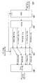
버추얼 서브캐리어(virtual sub-carrier)란, 시스템에 할당된 주파수 대역에 포함되는 다수의 서브캐리어 중, 데이터를 전송하는 데 사용되는 서브캐리어(데이터 서브캐리어)를 제외한 서브캐리어, 즉 데이터를 전송할 목적에는 사용되지 않는 서브캐리어이다. 다수의 서브캐리어 중, 어느 서브캐리어가 버추얼 서브캐리어인지에 대해서는, 시스템에서 고정적으로 설정되어 있다. 예를 들면, 도 1의 상측에 도시한 바와 같이, 비선형 증폭 시의 대역밖 방사 전력을 낮게 하기 위해, 시스템에 할당되어 있는 주파수 대역의 양단에 속하는 몇개의 서브캐리어가, 버추얼 서브캐리어로 설정된다(이에 대해서는, 예를 들면, 비특허 문헌2 참조). 또한, 도 1의 하측에 도시한 바와 같이, 수신 신호의 베이스 밴드 처리 시의 직류 드리프트를 저감시키기 위해, 주파수 대역의 중앙 부근의 서브캐리어도 버추얼 서브캐리어로 설정되는 경우가 있다(이에 대해서는, 예를 들면, 비특허 문헌3 참조). 구체적인 수치예로서는, 예를 들면 64개의 서브캐리어 중, 52개의 서브캐리어가 데이터 서브캐리어로 설정되며, 12개의 서브캐리어가 버추얼 서브캐리어로 설정된다. 이와 같이 고정적으로 설정된 버추얼 서브캐리어는 데이터 전송에 사용되지 않기 때문에, 송신 시의 변조 시에, 버추얼 서브캐리어에 관한 신호 성분은 제로로 설정된다.A virtual subcarrier is a subcarrier, ie, a purpose of transmitting data, excluding a subcarrier (data subcarrier) used for transmitting data, among a plurality of subcarriers included in a frequency band allocated to a system. Is a subcarrier not used. Of the plurality of subcarriers, which subcarrier is a virtual subcarrier is fixedly set in the system. For example, as shown in the upper side of FIG. 1, in order to lower the out-of-band radiated power during nonlinear amplification, some subcarriers belonging to both ends of the frequency band allocated to the system are set as virtual subcarriers. (See, for example, Non Patent Literature 2). In addition, as shown in the lower side of FIG. 1, in order to reduce the direct current drift in the baseband processing of the received signal, a subcarrier near the center of the frequency band may also be set as a virtual subcarrier. See, for example, Non Patent Literature 3). As a specific numerical example, for example, out of 64 subcarriers, 52 subcarriers are set as data subcarriers, and 12 subcarriers are set as virtual subcarriers. Since the virtual subcarrier set in this manner is not used for data transmission, the signal component related to the virtual subcarrier is set to zero at the time of modulation at the time of transmission.
도 2는 직교 주파수 분할 다중(OFDM : Orthogonal Frequency Division Multiplexing) 방식에서의 변조부의 개념도를 도시한다. OFDM 방식에서는, 신호의 변조는 고속 역푸리에 방식(IFFT)에 의해 행해진다. 이 때문에, 도면에서 좌측에 도시한 시계열의 송신 정보 데이터는, 직렬병렬 변환부(S/P)에 의해 병렬 신호로 변화되어, IFFT부에 입력된다. 이 병렬 신호에 포함되는 내용은 모두 데이터 서브캐리어에 대응된다. 또한, 버추얼 서브캐리어에 관한 신호 내용은, 고속 역푸리에 변환이 행해져, 변조된 병렬 신호가 출력되며, 이후 무선 송신에 필요한 처리를 거쳐 무선 송신이 행해진다.2 illustrates a conceptual diagram of a modulator in an orthogonal frequency division multiplexing (OFDM) scheme. In the OFDM scheme, signal modulation is performed by a fast inverse Fourier scheme (IFFT). For this reason, the transmission information data of the time series shown on the left side in the figure is changed into a parallel signal by the serial-parallel conversion unit S / P, and is input to the IFFT unit. All contents included in this parallel signal correspond to the data subcarriers. The signal content of the virtual subcarrier is subjected to fast inverse Fourier transform, and a modulated parallel signal is output, and then wireless transmission is performed through a process necessary for wireless transmission.
그러나, 이들 종래 기술은, 무선 신호를 구별하는 것을 의도하는 것은 아니기 때문에, 이들 기술을 이용해도, 동시에 주파수 자원을 이용하는 것은 곤란하다. 예를 들면, 임의의 유저 A가 무선 통신하고 있는 동안에, 다른 유저 B는 무선 통신을 할 수 없다. 예를 들면 유저 A, B가 지리적으로 서로 다른 장소에 있었다고 해도, 한쪽의 통신(타임 슬롯)이 종료될 때까지, 다른쪽은 대기하고 있어야만 한다. 이러한 상황은, 주파수의 이용 효율의 관점에서는 바람직하지 않다.However, since these prior arts do not intend to distinguish radio signals, it is difficult to use frequency resources at the same time even if these techniques are used. For example, while any user A is in wireless communication, the other user B cannot perform wireless communication. For example, even if users A and B are located at different geographical locations, the other party must wait until the end of one communication (time slot). Such a situation is not preferable from the viewpoint of frequency utilization efficiency.
[비특허 문헌1] 羽根秀一, 中ノ森將也, 原嘉孝, 原晋介, 「OFDM 널 스트링 어레이 안테나」, 전자 정보 통신 학회, 무선 통신 시스템 연구회, 2002-124, 2002년 7월[Non-Patent Document 1] 羽 根 秀 一, 中 ノ 森 將 也, 原 嘉 孝, 原 晋 介, 「OFDM Null String Array Antenna」, The Institute of Electronics and Information Communication, Wireless Communication Systems Research Society, 2002-124, July 2002
[비특허 문헌2] ARIB STD-B24, "Data Coding and Transmission Specification For Digital Broadcasting", ARIB, June 2000[Non-Patent Document 2] ARIB STD-B24, "Data Coding and Transmission Specification For Digital Broadcasting", ARIB, June 2000
[비특허 문헌3] ARIB STD-T70, "Lower Power Data Communication Systems Broadband Mobile Access Communication System(CSMA)", ARIB, Dec. 2000[Non-Patent Document 3] ARIB STD-T70, "Lower Power Data Communication Systems Broadband Mobile Access Communication System (CSMA)", ARIB, Dec. 2000
본 발명은, 상술한 바와 같은 문제에 대처하기 위해 이루어진 것으로, 그 목적은, 주파수의 이용 효율을 향상시키는 것이 가능한 멀티캐리어 무선 전송 시스템, 및 그와 같은 시스템에서 사용되는 송신 장치 및 수신 장치를 제공하는 것이다.SUMMARY OF THE INVENTION The present invention has been made to address the above problems, and an object thereof is to provide a multicarrier wireless transmission system capable of improving frequency utilization efficiency, and a transmission device and a reception device used in such a system. It is.
또한, 본 발명은, 무선 신호를 구별하면서 적응 어레이 안테나의 제어를 행함으로써, 주파수의 이용 효율을 향상시키는 것이 가능한 멀티캐리어 무선 전송 시스템, 및 그와 같은 시스템에서 사용되는 송신 장치 및 수신 장치를 제공하는 것을 목적으로 한다.The present invention also provides a multicarrier wireless transmission system capable of improving the efficiency of use of a frequency by performing control of an adaptive array antenna while discriminating a radio signal, and a transmission device and a reception device used in such a system. It aims to do it.
이들 목적은, 이하에 설명하는 수단에 의해 해결된다. 본 발명에 따르면, 데이터 전송에 사용되는 서브캐리어인 데이터 서브캐리어와, 데이터 전송에 사용되지 않는 서브캐리어인 버추얼 서브캐리어에 기초하여 무선 전송을 행하는 멀티캐리어 전송 시스템이 제공된다. 본 시스템에 사용되는 송신 장치에서는, 버추얼 캐리어로 설정되는 적어도 1개의 서브캐리어가, 서브캐리어의 배치 정보에 따라 동적으로 설정된다. 본 시스템에 사용되는 수신 장치는, 수신 신호에 포함되는 버추얼 서브캐리어에 관한 신호 성분이 제어되도록, 적응적으로 제어되는 적응 어레이 안테나 수단과, 적어도 일부의 버추얼 서브캐리어의 배치가 서로 다른 복수의 서브캐리어 배치 패턴 중, 어느 패턴을 이용하여 통신을 행할지를 설정하는 수단을 갖는다.These objects are solved by the means described below. According to the present invention, there is provided a multicarrier transmission system for performing wireless transmission based on a data subcarrier which is a subcarrier used for data transmission and a virtual subcarrier which is a subcarrier not used for data transmission. In the transmission apparatus used for this system, at least one subcarrier set as a virtual carrier is dynamically set according to the arrangement information of the subcarriers. The receiving apparatus used in the present system includes an adaptive array antenna means that is adaptively controlled so that a signal component relating to a virtual subcarrier included in a received signal is controlled, and a plurality of sub-different arrangements of at least some virtual subcarriers. It has a means which sets which pattern is performed using which of carrier arrangement patterns.
이에 의해, 서브캐리어의 배치 패턴에서의 버추얼 서브캐리어의 위치를, 통신을 행하는 송신 장치 및 수신 장치간에서 동적으로 변경할 수 있다. 송신 장치 또는 수신 장치는, 버추얼 서브캐리어의 배치 패턴을 나타내는 배치 정보에 응답하여, 데이터 서브캐리어로 설정되어 있었던 임의의 서브캐리어를 다시 데이터 서브캐리어로 설정하고, 버추얼 서브캐리어로 설정되어 있었던 임의의 서브캐리어를 다시 버추얼 서브캐리어로 설정한다. 임의의 배치 패턴 S1을 이용하여 송신된 무선 신호를 수신하는 수신 장치는, 버추얼 서브캐리어의 신호 성분을 억압하도록 안테나의 지향성 패턴을 적응 제어한다. 다른 배치 패턴 S2에 기초하는 무선 신호는, 억압되는 버추얼 서브캐리어에 의의가 있는 신호 성분을 갖기 때문에, 그 무선 신호에는 널이 향해진다. 따라서, 수신 장치는 동일한 배치 패턴 S1을 이용하는 신호를 양호하게 수신하는 한편, 별도의 배치 패턴 S2를 이용하는 신호를 억압할 수 있다. 즉, 본 발명에 따르면, 버추얼 서브캐리어의 위치(또는 배치 패턴)를 무선 신호의 식별 정보로서 사용하는 것이 가능하게 된다. 무선 신호를 구별하는 것이 가능하게 되기 때문에, 주파수 자원의 이용 효율을 종래보다 향상시키는 것이 가능하다.Thereby, the position of the virtual subcarrier in the arrangement pattern of the subcarrier can be changed dynamically between the transmitting device and the receiving device which perform communication. In response to the arrangement information indicating the arrangement pattern of the virtual subcarrier, the transmitting apparatus or the receiving apparatus sets any subcarrier set as the data subcarrier to the data subcarrier again, and any arbitrary subcarrier set as the virtual subcarrier. Set the subcarrier back to the virtual subcarrier. The receiving device which receives the radio signal transmitted using the arbitrary arrangement pattern S1 adaptively controls the directional pattern of the antenna to suppress the signal component of the virtual subcarrier. Since a radio signal based on another arrangement pattern S2 has a signal component meaningful to the virtual subcarrier being suppressed, null is directed to the radio signal. Therefore, the receiving device can satisfactorily receive a signal using the same arrangement pattern S1 while suppressing a signal using a separate arrangement pattern S2 . That is, according to the present invention, it becomes possible to use the position (or arrangement pattern) of the virtual subcarrier as identification information of the radio signal. Since it becomes possible to distinguish a radio signal, it is possible to improve the utilization efficiency of frequency resources compared with the former.
도 1은 서브캐리어의 배치 패턴을 도시하는 도면.1 is a diagram showing an arrangement pattern of subcarriers.
도 2는 OFDM 방식에서의 변조부의 개념도.2 is a conceptual diagram of a modulator in the OFDM scheme.
도 3은 본원 실시예에 따른 송신 장치의 주요한 기능에 관한 블록도.3 is a block diagram of the main functions of the transmitting apparatus according to the present embodiment;
도 4는 본원 실시예에 따른 수신 장치의 주요한 기능에 관한 블록도.4 is a block diagram of the main functions of the receiving apparatus according to the present embodiment;
도 5는 도 4에 도시한 적응 어레이 안테나부의 상세를 도시하는 블록도.FIG. 5 is a block diagram showing details of the adaptive array antenna unit shown in FIG. 4; FIG.
도 6은 본 발명의 동작 원리를 설명하기 위한 도면.6 is a view for explaining the principle of operation of the present invention.
도 7은 본원 실시예에 따른 별도의 송신 장치의 주요한 기능에 관한 블록도.7 is a block diagram of the main functions of a separate transmitter according to an embodiment of the present invention.
도 8은 본 발명을 셀룰러 통신 시스템에 사용한 경우의 양태를 도시하는 도면.FIG. 8 is a diagram showing aspects when the present invention is used in a cellular communication system. FIG.
도 9는 본 발명을 프라이빗 에리어 네트워크에 적용한 경우의 양태를 도시하는 도면.Fig. 9 is a diagram showing an embodiment when the present invention is applied to a private area network.
도 10은 서브캐리어의 배치 패턴을 도시하는 도면.10 is a diagram showing an arrangement pattern of subcarriers.
이하, 도면을 참조하면서 본원 실시예를 설명한다. 본원 실시예에 의한 통신 시스템은, 도 1에 도시한 바와 같은 종래의 서브캐리어 배치와 함께, 또는 그들과는 별개로 실현하는 것이 가능하다. 이하에 설명하는 기능 블록도에 도시되어 있는 요소의 적어도 일부는, 용도에 따라 소프트웨어에 의해 혹은 하드웨어에 의해 또는 양자의 조합에 의해 실현될 수 있다.Hereinafter, the present embodiment will be described with reference to the drawings. The communication system according to the embodiment of the present invention can be realized with or without the conventional subcarrier arrangement as shown in FIG. At least some of the elements shown in the functional block diagrams described below can be realized by software or by hardware or by a combination of the two depending on the purpose.
도 3은 본원 실시예에 따른 송신 장치의 주요한 기능에 관한 블록도이다. 송신 장치(300)는 직렬병렬 변환부(S/P)(302)를 갖고, 이것은 일련의 송신 정보 데이터인 직렬 신호로부터 순서대로 N-1개의 데이터를 추출하며, 그들을 N-1개의 신 호 계열에 대응시켜, 병렬 신호로서 출력한다. 단, N은 2 이상의 정수이다. 일련의 송신 정보 데이터는, 도시되어 있지 않은 부호기에 의해 부호화되어 있다. 다양한 부호화를 이용하는 것이 가능하며, 예를 들면 컨볼루션 부호화, 블록 부호화 등을 이용하는 것이 가능하다.3 is a block diagram of the main functions of the transmission apparatus according to the present embodiment. The
송신 장치(300)는 할당부(304)를 갖고, 이것은 N개의 신호 계열로 이루어지는 병렬 신호를 수신하며, 서브캐리어의 배치 정보에 기초하여 그들의 순서를 재배열한다. 할당부(304)에 입력되는 N개의 신호 계열 중, N-1개의 신호 계열은, 직렬병렬 변환부(302)로부터의 병렬 신호이며, 후에 데이터 서브캐리어에 관련지어진다. 할당부(304)에 입력되는 또 하나의 신호 계열은, 버추얼 서브캐리어에 관련지어지는 신호 계열이며, 이 신호 계열의 내용은, 예를 들면 제로의 값을 항상 나타내는 것(제로 데이터)이다.The transmitting
송신 장치(300)는 무선부(306)를 갖고, 이것은 N개의 신호 계열로 이루어지는 병렬 신호를 수신하며, 그들을 각 서브캐리어에 대응시켜 변조하여, 직렬 신호로 변환하고, 파형 정형 및 주파수 변환 등의 처리를 실시하여, 멀티캐리어 무선 신호를 출력한다. 멀티캐리어 무선 신호는, 도시되어 있지 않은 안테나부로부터 방사된다. 또한, 설명의 편의상 「송신 장치」로 언급하고 있지만, 실제로는 송신 기능뿐만 아니라 수신 기능도 구비하고 있다. 후술하는 「수신 장치」에 대해서도 마찬가지로, 수신 기능뿐만 아니라 송신 기능도 구비되어 있다.The transmitting
동작을 다음에 설명한다. 우선, 송신 장치(300)는, 통신을 개시할 때에, 예를 들면 셀룰러 시스템에서의 무선 기지국에 대하여, 통신 링크의 확립을 요구한 다. 이 요구는, 예를 들면 리퀘스트 투 센드(request to send)의 수순에 의해 행해질 수 있다. 이 요구 신호에 따라 적절한 무선 채널이 할당됨으로써, 무선 링크가 확립된다. 본 실시예에서는, 이 수순을 행할 때에, N개의 서브캐리어 중, 어느 서브캐리어를 버추얼 서브캐리어로 할지(또는 어느 서브캐리어를 데이터 서브캐리어로 할지)가 결정된다. 예를 들면, 통신 링크의 확립을 요구하는 신호에 긍정적으로 응답할 때에, 무선 기지국이 (또는 상위의 관리국으로부터의 지시 하에 무선 기지국이) k번째의 서브캐리어를 버추얼 서브캐리어로 하는 것을 통지한다. 단, k는 1 이상 N 이하의 정수이다. 긍정적인 응답은, 예를 들면 클리어 투 센드(CTR : clear to send)의 수순에 의해 행해질 수 있다. 혹은 반대로, 송신 장치(300)가, k번째의 서브캐리어를 버추얼 서브캐리어로 하는 것을 의뢰 또는 명령해도 된다. 어쨌든, 무선 링크의 양단의 노드에서, 어느 서브캐리어를 버추얼 서브캐리어로 설정할지, 즉 어떠한 서브캐리어 배치 패턴을 사용할지가 결정되면 된다. 이와 같이, 본 실시예에서는, 서브캐리어 배치 패턴에서의 적어도 1개의 버추얼 서브캐리어의 위치가, 동적으로 설정된다. 이러한 점은, 버추얼 서브캐리어의 위치가 고정적으로 취급되었던 종래의 방법과 크게 다르다.The operation is described next. First, at the start of communication, the transmitting
통신 링크가 확립되면, 송신 정보 데이터를 멀티캐리어 무선 신호로 변환하여 안테나부로부터 송신하기 위한 처리가 행해진다. 대체로, 실선의 화살표는, 수신측에 전송하는 송신 정보 데이터의 흐름을 나타내고, 파선의 화살표는 제로 데이터의 흐름을 나타낸다. 우선, 직병렬 변환기(302)에 의해, 1 : (N-1)의 비율로 직렬 신호가 병렬 신호로 변환된다. 이들 N-1개의 신호 계열에, 제로 데이터를 갖는 신호 계열을 가한 N개의 신호 계열이, 할당부(304)에 입력된다. 할당부(304)는, 서브캐리어의 배치 정보에 기초하여, 입력된 N개의 신호 계열의 순서를 재배열하여, 무선부(306)에 제공한다. 무선부(306)에서는, 의의가 있는 데이터 내용을 갖는 N-1개의 신호 계열(k번째를 제외한 모든 변조 데이터)과, 1개의 신호 계열(k번째의 제로 데이터 계열)의 N개의 신호 계열을 변조한다. 이 변조는, OFDM에 방식이면 역푸리에 변환을 행하게 되지만, 본 발명은 OFDM에 한정되지 않고, 예를 들면 발진기를 설치하도록 하여, 다른 맵핑을 행하는 것도 가능하다. 어느 방식을 채용하든, 서브캐리어마다 입력된 데이터를, 각 서브캐리어에 태울 수 있으면 된다. 이후, 파형 정형이나 주파수 변환 등의 기존의 방법을 이용하여, 멀티캐리어 무선 신호가 작성된다.When the communication link is established, processing for converting the transmission information data into a multicarrier radio signal for transmission from the antenna section is performed. In general, the solid arrow indicates the flow of transmission information data transmitted to the receiving side, and the broken line arrow indicates the flow of zero data. First, the serial-to-
도 4는 본원 실시예에 따른 수신 장치의 주요한 기능에 관한 블록도이다. 수신 장치(400)는, 적응 어레이 안테나부(402)를 갖는다. 적응 안테나부(402)는, 멀티캐리어 무선 신호의 불요한 신호 성분을 억제하면서 그것을 수신하여, 후단의 복조부(404)에 제공한다. 복조부(404)는, 멀티캐리어 무선 신호를 수신하고, N개의 신호 계열로 이루어지는 병렬 신호(복조 데이터1∼N)를 도출한다. 이 병렬 신호를 복조함으로써 서브캐리어마다의 N개의 신호 계열이 얻어진다. OFDM 방식이 채용되어 있으면, 이 복조는 고속 푸리에 변환에 의해 행해진다.4 is a block diagram of the main functions of the receiving apparatus according to the present embodiment. The
수신 장치(400)는 할당부(406)를 갖고, 이것은 N개의 신호 계열로 이루어지는 병렬 신호를 수신하며, 서브캐리어의 배치 정보에 기초하여 그들의 순서를 재배열한다. 보다 정확하게는, N개의 신호 계열(복조 데이터 계열) 중으로부터, 버추 얼 서브캐리어에 대응하는 신호 계열(k번째의 신호 계열)을 배제하고, N-1개의 신호 계열로 이루어지는 병렬 신호를 출력한다. 서브캐리어의 배치 정보는, 예를 들면, 송신 장치(300) 및 수신 장치(400) 사이의 통신 링크의 확립 시에 결정된다.The receiving
수신 장치(400)는 병렬직렬 변환부(P/S)(408)를 갖고, 이것은 병렬적으로 수신한 N-1개의 신호 계열로부터 얻어지는 데이터를 순서대로, 하나의 신호 계열로 변환함으로써, 수신 정보 데이터를 나타내는 신호 계열을 작성한다.The
도 5는 도 4에 도시한 적응 어레이 안테나부(402)의 상세를 도시하는 블록도이다. 도시한 바와 같이, 적응 어레이 안테나부(402)는, 복수의 (M개의) 안테나 소자(502)와, 안테나 소자(502)마다 설치된 아날로그 디지털 변환부(A/D)(504)를 갖는다. 적응 어레이 안테나부(402)는, 이들 안테나 소자(502)를 통해 얻어지는 신호에 가중치(웨이트)를 부가하기 위한 가중치 조정부(506)를 갖는다. 적응 어레이 안테나 소자(502)는 합성부(508)를 갖고, 이것은 안테나 소자(502)로부터의 신호를 적절하게 합성하여, 후단의 복조부(404)에 제공한다. 또한, 적응 어레이 안테나 소자(502)는 웨이트 제어부(510)를 갖고, 이것은 각 아테나 소자(502)에 의해 수신된 신호 Xi(n)에 기초하여, 가중치 조정부(506)에 제공하는 제어 신호 wj(n)을 산출한다. 단, i는 1 이상 M 이하의 정수이며, j는 2 이상 M 이하의 정수이고, n은 샘플 번호를 나타내는 파라미터이다.FIG. 5 is a block diagram showing details of the adaptive
각 안테나 소자(502)에서 수신된 신호는, 도시하지 않은 프론트 엔드에 의해 적절한 파형 정형 및 주파수 변환 등의 처리에 일임되며, 각자의 아날로그 디지털 변환부(504)를 통해, M개의 디지털 신호 Xi(n)이 얻어진다. 가중치 조정부(506)에서는, 이들의 디지털 신호 Xi(n)에 적절한 가중치가 부여되며, 합성부(508)에서 그들이 합성된다. 한편, 웨이트 제어부(510)는, 서브캐리어의 배치 정보에 의해 지정되는 버추얼 서브캐리어에 관한 신호 성분이 작아지도록(제로로 되도록) 제어 신호 wj(n)을 산출하고, 이 제어 신호 wj(n)에 응답하여, 가중치 조정부(506)에서 수신 신호에 가해지는 웨이트가 설정된다. 따라서, 합성부(508)로부터 출력되는 신호는, 버추얼 서브캐리어에 관한 신호 성분이 억제된 신호이다. 또한, w1(n)에 대응하는 가중치 조정부(506)가 도시되어 있지 않은 것은, 웨이트의 최적화를 행할 때에, 자명한 해가 출현하는 것을 회피하기 위해서이지만, 보다 일반적으로 w1(n)에 대응하는 가중치 조정부(506)를 설치하는 것도 가능하다.The signal received at each
상술한 바와 같이, 버추얼 서브캐리어는 데이터 전송에 사용되지 않는 서브캐리어이기 때문에, 수신 신호 중의 그 성분은 제로인 것이 바람직하다. 그러나, 주파수 오프셋 등의 간섭원에 기인하여, 수신 신호의 버추얼 서브캐리어에 관한 신호 성분이 제로로 되지 않는 경우에는, 그것이 간섭 성분으로 되어, 신호 품질을 열화시키게 된다. 버추얼 서브캐리어에 관한 신호 성분을 제로로 하도록 웨이트 wj(n)을 조정하면서 안테나의 지향성 패턴을 갱신해 감으로써, 수신 신호의 품질을 향상시키는 것이 가능하게 된다.As described above, since the virtual subcarrier is a subcarrier not used for data transmission, the component of the received signal is preferably zero. However, if a signal component with respect to the virtual subcarrier of the received signal does not become zero due to an interference source such as a frequency offset, it becomes an interference component and degrades signal quality. By updating the directional pattern of the antenna while adjusting the weight wj (n) to zero the signal component relating to the virtual subcarrier, it is possible to improve the quality of the received signal.
도 3에 도시한 송신 장치(300) 및 도 4에 도시한 수신 장치(400)를 이용하 면, 서브캐리어의 배치 정보를 사용하여, 송신 장치 및 수신 장치간에서, 버추얼 서브캐리어의 위치를 임의로 동적으로 변경시키는 것이 가능하게 된다. 즉 본 실시예에서는, 서브캐리어의 배치 패턴에서의 (적어도 일부의) 버추얼 서브캐리어의 위치가 고정되어 있지 않다.When using the
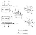
도 6은 본 발명의 원리를 설명하기 위한 설명도이다. 도 6에 도시한 바와 같이, 예를 들면, k번째의 서브캐리어를 버추얼 서브캐리어로 설정하고, m번째를 포함하는 다른 서브캐리어를 데이터 서브캐리어로 설정하여 통신을 행하는 무선 단말기 A와, m번째의 서브캐리어를 버추얼 서브캐리어로 설정하고, k번째를 포함하는 다른 서브캐리어를 데이터 서브캐리어로 설정하여 통신을 행하는 무선 단말기 B가 있는 것으로 한다. 무선 기지국측에서, k번째의 서브캐리어를 버추얼 서브캐리어로 설정하고, 버추얼 서브캐리어의 신호 성분이 작아지도록 안테나 패턴 PA를 변화시키면서 도래파를 수신하면, 무선 단말기 A로부터의 도래파를 양호하게 수신하는 한편, 무선 장치 B로부터의 도래파를 억제하는 것이 가능하게 된다. k번째의 서브캐리어의 신호 성분을 억압하도록 안테나의 지향성 패턴 PA를 조정함으로써, k번째의 서브캐리어를 데이터 서브캐리어로서 사용하는 송신 장치 B로부터의 도래파로 널을 향하게 하여 억압할 수 있기 때문이다. 도면에서 실선의 화살표는 무선 단말기 A로부터의 도래파를 나타내고, 파선의 화살표는 무선 단말기 B로부터의 도래파를 나타낸다. 마찬가지로, 무선 기지국에서 m번째의 서브캐리어를 버추얼 서브캐리어로 설정하고, 버추얼 서브캐리어의 신호 성분이 작아지도록 안테나 패턴 PB를 변화시키면서 도래파를 수신하면, 무선 단말기 B로부터의 도래파를 양호하게 수신하는 한편, 무선 장치 A로부터의 도래파를 억압하는 것이 가능하게 된다. 이것은, 버추얼 서브캐리어의 배치를 서로 다르게 함으로써, 무선 단말기 A, B로부터의 도래파를 구별할 수 있는 것을 의미한다. 다시 말하면, 서브캐리어의 배치 패턴이, 도래파를 구별하기 위한 식별 정보로 된다.6 is an explanatory diagram for explaining the principle of the present invention. As shown in Fig. 6, for example, the wireless terminal A which sets the kth subcarrier as a virtual subcarrier and sets another subcarrier including the mth as a data subcarrier to communicate with the mth th, It is assumed that there is a wireless terminal B that performs communication by setting the subcarrier to virtual subcarrier and the other subcarrier including the k-th as the data subcarrier. On the radio base station side, when the k-th subcarrier is set as the virtual subcarrier and the incoming wave is received while changing the antenna pattern PA so that the signal component of the virtual subcarrier becomes small, the arrival wave from the radio terminal A is satisfactorily achieved. While receiving, it is possible to suppress the wave coming from the wireless device B. This is because by adjusting the directional pattern PA of the antenna so as to suppress the signal component of the k-th subcarrier, it is possible to suppress the wave from the transmitting device B using the k-th subcarrier as the data subcarrier. . In the figure, the solid arrows indicate the wave coming from the wireless terminal A, and the dashed arrows indicate the wave coming from the wireless terminal B. FIG. Similarly, when the radio base station sets the mth subcarrier to the virtual subcarrier and receives the arrival wave while changing the antenna pattern PB so that the signal component of the virtual subcarrier becomes smaller, the arrival wave from the wireless terminal B is satisfactorily achieved. While receiving, it is possible to suppress the wave coming from the wireless device A. This means that the arrival waves from the wireless terminals A and B can be distinguished by different arrangement of the virtual subcarriers. In other words, the arrangement pattern of the subcarriers becomes identification information for distinguishing the arrival wave.
도 7은 본원 실시예에 따른 별도의 송신 장치의 주요한 기능에 관한 블록도이다. 대체로, 실선의 화살표는, 수신측에 전송하기 위한 송신 정보 데이터의 흐름을 나타내고, 파선의 화살표는 제로 데이터의 흐름을 나타낸다. 송신 장치(600)는 직렬병렬 변환기(S/P)(602)를 갖고, 이것은 일련의 송신 정보 데이터인 직렬 신호를 병렬 신호로 하여 출력한다. 일련의 송신 정보 데이터는, 도시하지 않은 부호기에 의해 부호화되어 있다. 다양한 부호화를 이용하는 것이 가능하며, 예를 들면 컨볼루션 부호화, 블록 부호화 등을 이용하는 것이 가능하다.7 is a block diagram of the main functions of a separate transmission apparatus according to the present embodiment. In general, the solid arrow indicates the flow of transmission information data for transmission to the receiving side, and the broken arrow indicates the flow of zero data. The
송신 장치(600)는 할당부(604)를 갖고, 이것은 N개의 신호 계열로 이루어지는 병렬 신호를 수신하며, 서브캐리어의 배치 정보에 의해 지정되는 신호 계열의 내용을, 버추얼 서브캐리어에 대응하는 신호 내용으로 설정한다. 설정 후의 신호 계열이 갖는 신호 내용은, 예를 들면 제로의 값을 항상 나타내는 것(제로 데이터)이다. 그 이외의 신호 계열에 대해서는, 그 상태 그대로 출력된다. 이와 같이 서브캐리어의 배치 정보는, N개의 서브캐리어 중, 어느 서브캐리어를 버추얼 서브캐리어로 할지(또는 어느 서브캐리어를 데이터 서브캐리어로 할지)를 나타내는 것이며, 이것은 통신 링크를 확립할 때에 결정된다.The transmitting
송신 장치(600)는 무선부(606)를 갖고, 이것은 N개의 신호 계열로 이루어지는 병렬 신호를 수신하며, 그것을 각 서브캐리어에 대응시켜 변조하여, 직렬 신호로 변환하고, 파형 정형 및 주파수 변환 등의 처리를 실시하여, 멀티캐리어 무선 신호를 출력한다. 변조는, OFDM 방식이면 역푸리에 변환을 행하게 되지만, 본 발명은 OFDM에 한정되지 않고, 다른 맵핑을 행하는 것도 가능하다. 멀티캐리어 무선 신호는, 도시되어 있지 않은 안테나부로부터 방사된다.The
본 실시예에서는, 직렬병렬 변환부(602)가 출력하는 신호 계열 수 N과, 무선부(606)가 수신하는 신호 계열 수 N이 동일하다. 따라서, 수신 장치측도, 복조된 N개의 신호 계열에 맞춰, N개의 신호 계열을 직렬 신호로 변환함으로써, 수신 정보 데이터를 얻을 수 있다. 도 4의 할당부(406)와 같은 신호 계열 수를 조정하는 요소는 불필요하다. 복조부로부터의 병렬 신호는 그 상태 그대로 직병렬 변환부에 제공된다. 단, k번째의 서브캐리어(버추얼 서브캐리어)에 관한 신호 성분이 작아지도록, 적응 어레이 안테나부에 의한 지향성의 제어가 행해지는 점은, 도 4의 수신 장치(400)와 마찬가지이다.In the present embodiment, the number N of signal sequences output from the serial-
본 실시예에서는, S/P(602)로부터 출력되는 송신 정보 데이터를 나타내는 N개의 신호 계열 중, 하나의 신호 계열(k번째)이 제로로 억제된 후에 무선부(606)에 입력되어, 송신 정보 데이터의 일부가 소실된다. 그러나, 직병렬 변환부(602)에 입력되는 송신 정보 데이터가 적절하게 부호화되어 있으면, N개의 데이터의 일부가 결락되었다고 해도, 수신측에서 적절하게 복원하는 것이 가능하다. 무릇 부호화는, 통신 환경이 악화되어 송신 환경 데이터의 일부가 소실되었다고 해도, 그것을 복호함으로써 송신 데이터를 적절하게 복원하는 것을 가능하게 한다. N개의 신호 계열 중, k번째의 신호 계열의 내용을 제로로 하는 것은, 수신측에서 보면, 그 정도로 통신 환경이 나쁘다는 것과 등가이다.In the present embodiment, one signal sequence (kth) of the N signal sequences representing the transmission information data output from the S /
이와 같이 본 실시예에서는, 송신 데이터의 일부를 희생함으로써, 송신 신호를 식별 가능하게 함과 함께, 데이터 전송 속도를 종래와 동일한 정도를 유지하는 것이 가능하게 된다. 도 3에 도시한 실시예에서는, 송신 데이터를 의도적으로 희생하지 않지만, 데이터 전송 속도는 종래의 (N-1)/N배로 되게 된다. 또한, 도 3에 도시한 바와 같은 송신 장치를 사용하는 경우에는, 이것에 맞춰 도 4에 도시한 바와 같은 수신 장치를 필요로 한다. 이에 대하여, 도 7에 도시한 바와 같은 송신 장치를 사용할 때에는, 종래의 요소에 대한 수정은 적어진다. 송신 장치(600)에 관해서는, 서브캐리어의 배치 정보에 의해 지정된 신호 계열을 제로로 설정 가능하게 함으로써 족하다. 수신 장치에 관해서는, 적응 어레이 안테나부가, 서브캐리어의 배치 정보에 의해 지정된 서브캐리어의 신호 성분을 억압하도록 제어 가능하게 함으로써 족하다. 따라서, 데이터의 신뢰성 등의 관점에서는 도 3에 도시한 실시예가 바람직하고, 데이터의 전송 속도나 기존 시스템에 대한 수정량 등의 관점에서는, 도 7에 도시한 실시예가 바람직하다. 이것은, 설정되는 버추얼 서브캐리어 수가 증가할수록 현저해지는 경향에 있다.As described above, in the present embodiment, at the expense of a part of the transmission data, the transmission signal can be identified and the data transmission speed can be maintained at the same level as before. In the embodiment shown in Fig. 3, the transmission data is not intentionally sacrificed, but the data transfer rate is conventional (N-1) / N times. In addition, when using the transmitter shown in FIG. 3, the receiver shown in FIG. 4 is required accordingly. On the other hand, when using the transmission apparatus shown in FIG. 7, the correction with respect to a conventional element becomes few. Regarding the
도 8은 본 발명을 셀룰러 통신 시스템의 상승 회선에 사용한 경우의 양태를 도시한다. 이 시스템에서는, 셀 A∼G 중에서, 인접하는 셀끼리의 사이에서는 서로 다른 서브캐리어의 배치 패턴을 사용하도록 설정되어 있다. 구체적으로는, 셀 A에 서는 m번째, 셀 F, B, D에서는 n번째, 셀 G, C, E에서는 k번째의 서브캐리어가 버추얼 서브캐리어로 설정되고, 그 이외에는 데이터 서브캐리어로 설정되어 있다. 각 셀 중에서는 동일한 서브캐리어의 배치 패턴을 이용하여 통신이 행해진다. 따라서, 1개의 셀 내에서는 시분할 형식으로 무선 기지국과 무선 단말기가 통신을 행한다. 셀 A의 무선 기지국(도시 생략)은, m번째의 서브캐리어에 관한 신호 성분을 억압하도록 적응 어레이 안테나부를 제어함으로써, 자셀로부터의 도래파를 양호하게 수신하는 한편, 인접하는 셀로부터의 도래파(간섭파)를 억압하도록, 지향성 패턴 PA를 조정할 수 있다. 이와 같이, 셀룰러 통신 시스템의 셀(또는 섹터)마다, 서브캐리어의 배치 패턴을 상위하게 함으로써, 자타의 셀(또는 섹터)을 식별하는 것이 가능하다.8 shows an aspect in the case where the present invention is used in an uplink of a cellular communication system. In this system, cells A to G are set to use different subcarrier arrangement patterns between adjacent cells. Specifically, the mth cell in cell A, the nth cell in cells F, B, and D, and the kth subcarrier in cells G, C, and E are set as virtual subcarriers, and the data subcarriers are otherwise set. . In each cell, communication is performed using the arrangement pattern of the same subcarrier. Therefore, the wireless base station and the wireless terminal communicate in time division format in one cell. The radio base station (not shown) of the cell A controls the adaptive array antenna unit so as to suppress the signal component relating to the mth subcarrier, thereby receiving well the incoming wave from its cell and arriving wave from an adjacent cell. The directional pattern PA can be adjusted to suppress the interference wave). In this manner, it is possible to identify other cells (or sectors) by making the subcarrier arrangement pattern different for each cell (or sector) of the cellular communication system.
도 9는 본 발명을 사설망 또는 프라이빗 에리어 네트워크(PAN : Private Area Network)에 적용한 경우의 양태를 도시한다. 도시한 바와 같이, 인접하는 2개의 그룹 A, B가 존재하고, 그룹 내의 통신 단말기는, 적응 어레이 안테나를 갖는 송수신기로서의 기능을 갖는다. 그룹 A, B는, 서로 다른 서브캐리어의 배치 패턴을 사용한다. 그룹 A에서는 m번째의 서브캐리어를, 그룹 B에서는 k번째의 서브캐리어를 버추얼 서브캐리어로 설정하고, 다른 서브캐리어는 데이터 서브캐리어로 설정된다. 동일 그룹 내에서는 동일한 배치 패턴에 기초하여 통신을 행한다. 이와 같이 시스템을 구성함으로써, 통신 단말기는 자신이 소속하는 그룹 이외의 그룹으로부터의 도래파를 억제하면서 통신을 행할 수 있다.FIG. 9 shows an embodiment in which the present invention is applied to a private network or a private area network (PAN). As shown, two adjacent groups A and B exist, and the communication terminals in the group have a function as a transceiver having an adaptive array antenna. Groups A and B use arrangement patterns of different subcarriers. In group A, the mth subcarrier is set, in group B, the kth subcarrier is set as a virtual subcarrier, and the other subcarriers are set as data subcarriers. In the same group, communication is performed based on the same arrangement pattern. By configuring the system in this way, the communication terminal can communicate while suppressing the arrival waves from groups other than the group to which the communication terminal belongs.
상술한 바와 같이, 동일 그룹 내에서는 동일 배치 패턴을 이용하기 때문에, 예를 들면 그룹 A에 속하는 통신 단말기(902)가 통신하고 있는 동안에, 통신 단말기(904)는 통신을 할 수 없다. 동일 그룹 내의 통신의 경합 또는 충돌을 회피하는 데에는, 다양한 방법이 있다. 예를 들면, 통신 단말기(904)가 통신을 개시하기 전에, k번째의 서브캐리어에 관련되는 신호 성분을 조사하는 것이 유리하다. 그 신호 성분이 의의가 있는 크기이면, 그룹 내의 누군가가(예를 들면 통신 단말기(902)) 이미 통신을 행하고 있기 때문에, 통신 단말기(904)는 신호를 송신해서는 안된다는 것을 알 수 있다. 반대로, 그 신호 성분이 제로이면, 그 그룹 내에서 아무도 통신을 행하고 있지 않은 것을 알 수 있다. 그룹 B로부터의 도래파에 대해서는, k번째의 서브캐리어는 버추얼로 설정되어 있기 때문에, 그룹 B에서의 도래파가 있었다고 해도 검출되는 신호 성분의 크기는 제로이다. 따라서, k번째의 서브캐리어에 관한 신호 성분의 유무는, 그룹 A 내에서 통신하고 있는 통신 단말기의 존부로 직결된다. 또한, k+1번째의 서브캐리어의 신호 성분의 유무를 조사하는 것은 적절하지 않다. 신호 성분이 검출된 경우에, 그것이 그룹 A 내의 것인지 그룹 B로부터의 것인지를 구별할 수 없기 때문이다. 마찬가지로, 그룹 B에서는, 통신을 개시하기 전에 m번째의 서브캐리어의 신호 성분을 조사함으로써, 동일 그룹 내의 통신의 경합을 회피하는 것이 가능하게 된다. 이와 같이, 서로 다른 서브캐리어 배치 패턴을 이용하는 복수의 그룹 중 어느 하나에 소속하는 통신 단말기는, 자신이 속하는 그룹 이외에서 사용되는 서브캐리어 배치 패턴에서, 버추얼 서브캐리어로 설정되어 있는 서브캐리어의 신호 성분의 크기를 조사함으로써, 신호 송신의 가부를 판단하는 것이 가능하다.As described above, since the same arrangement pattern is used within the same group, for example, while the
이상에서 설명한 실시예에서는, 1개의 버추얼 서브캐리어의 위치를 변경함으로써, 통신 단말기, 셀(또는 섹터), 그룹 등을 구별하였다. 그러나, 본 발명은 그와 같은 형태에 한정되지 않고, 버추얼 서브캐리어의 다양한 배치 패턴을 이용하여, 무선 신호를 구별하는 것을 가능하게 한다.In the embodiment described above, the communication terminal, cell (or sector), group, and the like are distinguished by changing the position of one virtual subcarrier. However, the present invention is not limited to such a form, and makes it possible to distinguish radio signals by using various arrangement patterns of virtual subcarriers.
도 10은 프라이빗 에리어 네트워크에서의 3개의 그룹을 구별하는 데 사용하는 것이 가능한 서브캐리어의 배치 패턴을 도시한다. 간단하게 하기 위해, 6개의 서브캐리어만 도시하고 있지만, 더 많은 서브캐리어를 배치하는 것이 가능하다. 도시한 바와 같이, 그룹 A에서는 서브캐리어 f3, f5가, 그룹 B에서는 서브캐리어 f1, f3이, 그룹 C에서는 서브캐리어 f1, f5가, 버추얼 서브캐리어로 설정되고, 다른 서브캐리어는 데이터 서브캐리어로 설정되어 있다. 그룹 A 내에서 통신을 행하고 있는 동안에는, 도래파에 포함되는 서브캐리어 f3, f5의 신호 성분이 억압되도록 지향성 패턴이 조정되기 때문에, 다른 그룹 B, C로부터의 도래파를 효과적으로 억압할 수 있다. 그룹 A 내에서 통신을 개시하고자 할 때에는, 서브캐리어 f1의 신호 성분의 유무를 조사한다. 서브캐리어 f1은 그룹 B, C에서는 버추얼 서브캐리어로 설정되어 있기 때문에, 그룹 B, C로부터의 기여는 실질적으로 제로이다. 따라서, 서브캐리어 f1의 신호 성분의 유무는, 그룹 A에서의 통화 중인 통신 단말기의 유무로 직결되게 된다. 마찬가지로, 그룹 B에서는 서브캐리어 f5의 신호 성분의 유무를 조사함으로써 충돌을 회피할 수 있다. 그룹 C에서는 서브캐리어 f3의 신호 성분의 유무를 조사함으로써 충돌을 회피할 수 있다. 이렇게 해서, 동일 그룹 내에서의 충돌을 회피하고, 또한 다른 그룹으로부터의 도래파를 억압하는 것이 가능하게 된다.10 shows a placement pattern of subcarriers that can be used to distinguish three groups in a private area network. For simplicity, only six subcarriers are shown, but it is possible to place more subcarriers. As shown, subcarriers f3 and f5 are set in group A, subcarriers f1 and f3 are set in group B, and subcarriers f1 and f5 are set as virtual subcarriers in group C. The carrier is set to a data subcarrier. While performing communication in the group A, since the directional pattern is adjusted so that the signal components of the subcarriers f3 and f5 included in the arriving wave are suppressed, the arrival wave from the other groups B and C can be effectively suppressed. . When communication is to be started in group A, the presence or absence of a signal component of subcarrier f1 is checked. Since subcarriers f1 are set to virtual subcarriers in groups B and C, the contributions from groups B and C are substantially zero. Therefore, the presence or absence of a signal component of the subcarrier f1 is directly connected to the presence or absence of a communication terminal in a call in group A. Similarly, in group B, collision can be avoided by examining the presence or absence of a signal component of subcarrier f5 . In group C, collision can be avoided by examining the presence or absence of a signal component of subcarrier f3 . In this way, it is possible to avoid collisions in the same group and suppress incoming waves from other groups.
보다 일반적으로는, N개의 그룹을 구별하기 위해서는, 적어도 N-1개의 서브캐리어를 버추얼 서브캐리어로 설정하고, N개의 서로 다른 배치 패턴을 형성하는 것을 필요로 한다. 또한, 동일 그룹 내에서의 충돌을 회피할 수 있도록 하기 위해서는, 임의의 1개의 배치 패턴에서 데이터 서브캐리어로 설정되어 있는 적어도 1개의 서브캐리어(예를 들면, 그룹 A에서는 f1, 그룹 B에서는 f5, 그룹 C에서는 f3)가, 다른 N-1개 모두의 배치 패턴에서 버추얼 서브캐리어로 설정되어 있도록 할 필요가 있다. 그 서브캐리어의 신호 성분의 유무를 통신 개시 전에 조사함으로써, 동일 그룹 내에서 이미 통신이 이루어져 있는지의 여부를 판별하는 것이 가능하게 된다. 이러한 서브캐리어의 배치 패턴은, 프라이빗 에리어 네트워크의 그룹의 식별에 한하지 않고, 임의의 도래파를 식별하기 위해 사용하는 것이 가능하다.More generally, in order to distinguish N groups, it is necessary to set at least N-1 subcarriers as virtual subcarriers and form N different arrangement patterns. In order to avoid collisions in the same group, at least one subcarrier (for example, f1 in group A and f in group B) set as a data subcarrier in any one arrangement pattern5 , in group C, f3 ) needs to be set as a virtual subcarrier in all other N-1 arrangement patterns. By checking the presence or absence of the signal component of the subcarrier before the start of communication, it is possible to determine whether communication has already been made in the same group. The arrangement pattern of such subcarriers is not limited to the identification of the group of the private area network, but can be used to identify any coming wave.
이상, 본 발명의 바람직한 실시예를 설명하였지만, 본 발명은 이에 한정되는 것이 아니라, 본 발명의 요지의 범위 내에서 다양한 변형 및 변경이 가능하다.As mentioned above, although preferred embodiment of this invention was described, this invention is not limited to this, A various deformation | transformation and a change are possible within the scope of the summary of this invention.
Claims (17)
Translated fromKoreanPriority Applications (1)
| Application Number | Priority Date | Filing Date | Title |
|---|---|---|---|
| KR1020057014251AKR100697144B1 (en) | 2005-08-03 | 2003-06-30 | Multicarrier radio transmission systems, transmitters and receivers |
Applications Claiming Priority (1)
| Application Number | Priority Date | Filing Date | Title |
|---|---|---|---|
| KR1020057014251AKR100697144B1 (en) | 2005-08-03 | 2003-06-30 | Multicarrier radio transmission systems, transmitters and receivers |
Publications (2)
| Publication Number | Publication Date |
|---|---|
| KR20050106411A KR20050106411A (en) | 2005-11-09 |
| KR100697144B1true KR100697144B1 (en) | 2007-03-20 |
Family
ID=37283281
Family Applications (1)
| Application Number | Title | Priority Date | Filing Date |
|---|---|---|---|
| KR1020057014251AExpired - Fee RelatedKR100697144B1 (en) | 2005-08-03 | 2003-06-30 | Multicarrier radio transmission systems, transmitters and receivers |
Country Status (1)
| Country | Link |
|---|---|
| KR (1) | KR100697144B1 (en) |
Citations (2)
| Publication number | Priority date | Publication date | Assignee | Title |
|---|---|---|---|---|
| JP2001148678A (en)* | 1999-11-19 | 2001-05-29 | Yrp Mobile Telecommunications Key Tech Res Lab Co Ltd | Multi-carrier communication equipment |
| JP2001339361A (en)* | 2000-05-29 | 2001-12-07 | Matsushita Electric Ind Co Ltd | Multi-carrier communication device and multi-carrier communication method |
- 2003
- 2003-06-30KRKR1020057014251Apatent/KR100697144B1/ennot_activeExpired - Fee Related
Patent Citations (2)
| Publication number | Priority date | Publication date | Assignee | Title |
|---|---|---|---|---|
| JP2001148678A (en)* | 1999-11-19 | 2001-05-29 | Yrp Mobile Telecommunications Key Tech Res Lab Co Ltd | Multi-carrier communication equipment |
| JP2001339361A (en)* | 2000-05-29 | 2001-12-07 | Matsushita Electric Ind Co Ltd | Multi-carrier communication device and multi-carrier communication method |
Non-Patent Citations (2)
| Title |
|---|
| IEEE 2001년 논문 "A novel OFDM adaptive antenna a* |
| 일본공개특허공보 평13-148678호 * |
Also Published As
| Publication number | Publication date |
|---|---|
| KR20050106411A (en) | 2005-11-09 |
Similar Documents
| Publication | Publication Date | Title |
|---|---|---|
| US10084585B2 (en) | Wireless communication apparatus and wireless communication method | |
| WO2024046138A1 (en) | Wireless baseband processing method and apparatus implementing integrated sensing and communication | |
| CN103178884B (en) | Multiple-input and multiple-output (MIMO) transmitter, equipment, system and the method communicated in the wireless network | |
| KR102105051B1 (en) | Apparatus and method for operating a device in a wireless communication system | |
| KR100883942B1 (en) | Multiplexing of Real-time and Non-Real-Time Services of OPDM System | |
| RU2518085C2 (en) | Method for channelisation in wireless communication network (versions) and central station used in wireless communication system | |
| JP3670445B2 (en) | Wireless communication system | |
| JP4143643B2 (en) | Multi-carrier wireless transmission system, transmitting apparatus and receiving apparatus | |
| WO2010032791A1 (en) | Base station apparatuses, terminal apparatuses, wireless communication system having those apparatuses, and programs base stations of that system are caused to execute | |
| KR20100133497A (en) | Method and system for providing uplink structure and minimizing pilot signal overhead in wireless communication network | |
| US8306141B2 (en) | Method and a device for determining shifting parameters to be used by at least a first and a second telecommunication devices | |
| US9543992B2 (en) | Simulcasting MIMO communication system | |
| CN101499988A (en) | Wideband wireless mobile communication method, system and equipment | |
| JP2001111518A (en) | Communication method and communication device | |
| TW202412498A (en) | Antenna switching in frequency bands with power spectral density (psd) limits | |
| KR100697144B1 (en) | Multicarrier radio transmission systems, transmitters and receivers | |
| JP2004254335A (en) | Wireless base station, wireless terminal | |
| KR101359840B1 (en) | Apprarus and method for allocating resource in communication system using ofdm |
Legal Events
| Date | Code | Title | Description |
|---|---|---|---|
| A201 | Request for examination | ||
| PA0105 | International application | St.27 status event code:A-0-1-A10-A15-nap-PA0105 | |
| PA0201 | Request for examination | St.27 status event code:A-1-2-D10-D11-exm-PA0201 | |
| PG1501 | Laying open of application | St.27 status event code:A-1-1-Q10-Q12-nap-PG1501 | |
| E902 | Notification of reason for refusal | ||
| PE0902 | Notice of grounds for rejection | St.27 status event code:A-1-2-D10-D21-exm-PE0902 | |
| T11-X000 | Administrative time limit extension requested | St.27 status event code:U-3-3-T10-T11-oth-X000 | |
| E13-X000 | Pre-grant limitation requested | St.27 status event code:A-2-3-E10-E13-lim-X000 | |
| P11-X000 | Amendment of application requested | St.27 status event code:A-2-2-P10-P11-nap-X000 | |
| P13-X000 | Application amended | St.27 status event code:A-2-2-P10-P13-nap-X000 | |
| E701 | Decision to grant or registration of patent right | ||
| PE0701 | Decision of registration | St.27 status event code:A-1-2-D10-D22-exm-PE0701 | |
| GRNT | Written decision to grant | ||
| PR0701 | Registration of establishment | St.27 status event code:A-2-4-F10-F11-exm-PR0701 | |
| PR1002 | Payment of registration fee | St.27 status event code:A-2-2-U10-U12-oth-PR1002 Fee payment year number:1 | |
| PG1601 | Publication of registration | St.27 status event code:A-4-4-Q10-Q13-nap-PG1601 | |
| R17-X000 | Change to representative recorded | St.27 status event code:A-5-5-R10-R17-oth-X000 | |
| PR1001 | Payment of annual fee | St.27 status event code:A-4-4-U10-U11-oth-PR1001 Fee payment year number:4 | |
| PR1001 | Payment of annual fee | St.27 status event code:A-4-4-U10-U11-oth-PR1001 Fee payment year number:5 | |
| PR1001 | Payment of annual fee | St.27 status event code:A-4-4-U10-U11-oth-PR1001 Fee payment year number:6 | |
| FPAY | Annual fee payment | Payment date:20130227 Year of fee payment:7 | |
| PR1001 | Payment of annual fee | St.27 status event code:A-4-4-U10-U11-oth-PR1001 Fee payment year number:7 | |
| FPAY | Annual fee payment | Payment date:20140220 Year of fee payment:8 | |
| PR1001 | Payment of annual fee | St.27 status event code:A-4-4-U10-U11-oth-PR1001 Fee payment year number:8 | |
| FPAY | Annual fee payment | Payment date:20150224 Year of fee payment:9 | |
| PR1001 | Payment of annual fee | St.27 status event code:A-4-4-U10-U11-oth-PR1001 Fee payment year number:9 | |
| LAPS | Lapse due to unpaid annual fee | ||
| PC1903 | Unpaid annual fee | St.27 status event code:A-4-4-U10-U13-oth-PC1903 Not in force date:20160314 Payment event data comment text:Termination Category : DEFAULT_OF_REGISTRATION_FEE | |
| PC1903 | Unpaid annual fee | St.27 status event code:N-4-6-H10-H13-oth-PC1903 Ip right cessation event data comment text:Termination Category : DEFAULT_OF_REGISTRATION_FEE Not in force date:20160314 | |
| P22-X000 | Classification modified | St.27 status event code:A-4-4-P10-P22-nap-X000 |