KR100694925B1 - Portable terminal equipment - Google Patents
Portable terminal equipmentDownload PDFInfo
- Publication number
- KR100694925B1 KR100694925B1KR1020040056976AKR20040056976AKR100694925B1KR 100694925 B1KR100694925 B1KR 100694925B1KR 1020040056976 AKR1020040056976 AKR 1020040056976AKR 20040056976 AKR20040056976 AKR 20040056976AKR 100694925 B1KR100694925 B1KR 100694925B1
- Authority
- KR
- South Korea
- Prior art keywords
- camera unit
- portable terminal
- photographing
- terminal device
- camera
- Prior art date
- Legal status (The legal status is an assumption and is not a legal conclusion. Google has not performed a legal analysis and makes no representation as to the accuracy of the status listed.)
- Expired - Fee Related
Links
Images


Classifications
- H—ELECTRICITY
- H04—ELECTRIC COMMUNICATION TECHNIQUE
- H04M—TELEPHONIC COMMUNICATION
- H04M1/00—Substation equipment, e.g. for use by subscribers
- H04M1/02—Constructional features of telephone sets
- H04M1/0202—Portable telephone sets, e.g. cordless phones, mobile phones or bar type handsets
- H04M1/0206—Portable telephones comprising a plurality of mechanically joined movable body parts, e.g. hinged housings
- H04M1/0208—Portable telephones comprising a plurality of mechanically joined movable body parts, e.g. hinged housings characterized by the relative motions of the body parts
- H04M1/0214—Foldable telephones, i.e. with body parts pivoting to an open position around an axis parallel to the plane they define in closed position
- H—ELECTRICITY
- H04—ELECTRIC COMMUNICATION TECHNIQUE
- H04B—TRANSMISSION
- H04B1/00—Details of transmission systems, not covered by a single one of groups H04B3/00 - H04B13/00; Details of transmission systems not characterised by the medium used for transmission
- H04B1/38—Transceivers, i.e. devices in which transmitter and receiver form a structural unit and in which at least one part is used for functions of transmitting and receiving
- H—ELECTRICITY
- H04—ELECTRIC COMMUNICATION TECHNIQUE
- H04M—TELEPHONIC COMMUNICATION
- H04M1/00—Substation equipment, e.g. for use by subscribers
- H04M1/02—Constructional features of telephone sets
- H04M1/0202—Portable telephone sets, e.g. cordless phones, mobile phones or bar type handsets
- H04M1/026—Details of the structure or mounting of specific components
- H04M1/0264—Details of the structure or mounting of specific components for a camera module assembly
- H—ELECTRICITY
- H04—ELECTRIC COMMUNICATION TECHNIQUE
- H04N—PICTORIAL COMMUNICATION, e.g. TELEVISION
- H04N23/00—Cameras or camera modules comprising electronic image sensors; Control thereof
- H04N23/50—Constructional details
- H04N23/51—Housings
- H—ELECTRICITY
- H04—ELECTRIC COMMUNICATION TECHNIQUE
- H04N—PICTORIAL COMMUNICATION, e.g. TELEVISION
- H04N23/00—Cameras or camera modules comprising electronic image sensors; Control thereof
- H04N23/56—Cameras or camera modules comprising electronic image sensors; Control thereof provided with illuminating means
- H—ELECTRICITY
- H04—ELECTRIC COMMUNICATION TECHNIQUE
- H04N—PICTORIAL COMMUNICATION, e.g. TELEVISION
- H04N23/00—Cameras or camera modules comprising electronic image sensors; Control thereof
- H04N23/60—Control of cameras or camera modules
- H04N23/695—Control of camera direction for changing a field of view, e.g. pan, tilt or based on tracking of objects
Landscapes
- Engineering & Computer Science (AREA)
- Signal Processing (AREA)
- Multimedia (AREA)
- Computer Networks & Wireless Communication (AREA)
- Studio Devices (AREA)
Abstract
Translated fromKoreanDescription
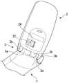
Translated fromKorean도 1은, 본 발명의 제 1 실시 형태에 따른 휴대 단말장치의 개방상태를 전면측에서 본 사시도,1 is a perspective view of an open state of a portable terminal device according to a first embodiment of the present invention, as viewed from the front side;
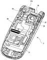
도 2는, 본 발명의 제 1 실시 형태에 따른 휴대 단말장치의 개방상태를 이면측에서 본 사시도,2 is a perspective view of an open state of the portable terminal device according to the first embodiment of the present invention, as viewed from the back side;
도 3은, 본 발명의 제 1 실시 형태에 따른 휴대 단말장치에 설치된 카메라 유닛의 설치 상태를 도시하는 사시도,3 is a perspective view showing an installation state of a camera unit installed in the portable terminal device according to the first embodiment of the present invention;
도 4는 도 1의 A-A선 단면도,4 is a cross-sectional view taken along the line A-A of FIG.
도 5는, 본 발명의 제 1 실시 형태에 따른 휴대 단말장치에 설치된 클릭 기구의 단면도,5 is a cross-sectional view of the click mechanism provided in the portable terminal device according to the first embodiment of the present invention;
도 6은, 본 발명의 제 1 실시 형태에 따른 휴대 단말장치에 설치된 카메라 유닛을 도시하는 사시도,6 is a perspective view showing a camera unit installed in the portable terminal device according to the first embodiment of the present invention;
도 7은, 본 발명의 제 1 실시 형태에 따른 휴대 단말장치에 설치된 카메라 유닛을 도시하는 사시도이며, 검출 기구 주변에 대해서 도시한 도면,FIG. 7 is a perspective view showing a camera unit provided in the portable terminal device according to the first embodiment of the present invention.
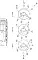
도 8은 검출 기구의 동작 원리에 대해서 설명한 도면,8 is a view explaining the principle of operation of the detection mechanism;
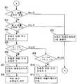
도 9는, 본 발명의 제 1 실시 형태에 따른 휴대 단말장치의 카메라 애플리케 이션 기동에 관한 흐름도,9 is a flowchart of a camera application startup of a portable terminal device according to the first embodiment of the present invention;
도 10은 종래의 휴대 단말장치의 사시도로서, 카메라 유닛이 렌즈 커버에 덮여 있는 상태를 도시한 도면,10 is a perspective view of a conventional portable terminal device, showing a state in which a camera unit is covered with a lens cover;
도 11은 동 휴대 단말장치의 사시도로서, 카메라 유닛이 노출한 상태를 도시한 도면,11 is a perspective view of the portable terminal device, showing a state where the camera unit is exposed;
도 12는, 본 발명의 제 2 실시 형태에 따른 휴대 단말장치의 개방된 상태를 전면측에서 본 사시도,12 is a perspective view of an open state of a portable terminal device according to a second embodiment of the present invention, as viewed from the front side thereof;
도 13은 본 발명의 제 2 실시 형태에 따른 휴대 단말장치의 개방된 상태를 이면측에서 본 사시도,13 is a perspective view of an open state of a portable terminal device according to a second embodiment of the present invention, as viewed from the back side;
도 14는, 본 발명의 제 2 실시 형태에 따른 휴대 단말장치의 표시측 하우징의 개략 확대 단면도,14 is a schematic enlarged cross-sectional view of a display side housing of a portable terminal device according to a second embodiment of the present invention;
도 15는, 본 발명의 제 2 실시 형태에 따른 휴대 단말장치에 설치된 카메라 유닛의 전개도.15 is an exploded view of a camera unit installed in a portable terminal device according to a second embodiment of the present invention.
도면의 주요 부분에 대한 부호의 설명Explanation of symbols for the main parts of the drawings
1 : 하부 하우징2 : 상부 하우징1: lower housing 2: upper housing
11 : 조작부21 : 표시부11: operation unit 21: display unit
22 : 카메라 유닛22a : 축22:
23 : 회전체24 : 카메라 모듈23: rotating body 24: camera module
25 : 발광부26 : 플렉시블 기판25
28 : 검출 기구28a : 제 1 검출 스위치28:
28b : 제 2 검출 스위치B : 분할 선28b: second detection switch B: split line
101 : 휴대 단말장치102 : 표시측 하우징101: portable terminal device 102: display side housing
122 : 카메라 유닛126 : 제 1 개구부122: camera unit 126: first opening
127 : 제 2 개구부128 : 케이싱127: second opening 128: casing
129 : 카메라131 : 제 1 지표부재129
132 : 제 2 지표부재133 : 제 1 라벨 부재132: second index member 133: first label member
134 : 제 2 라벨 부재134: second label member
본 발명은, 회전 가능한 카메라 유닛을 탑재한 휴대전화, PDA(Personal Digital Assistant), 디지털 카메라, 노트 북 등의 휴대 단말장치에 관한 것이다.BACKGROUND OF THE
본원은 2003년 7월 24일에 출원된 일본 특허출원 제 2003-201099 호 및 2003년 7월 24일에 출원된 일본 특허출원 제 2003-201100 호에 대하여 우선권을 주장하고, 그 내용을 여기에 원용한다. This application claims priority with respect to Japanese Patent Application No. 2003-201099 for which it applied on July 24, 2003, and Japanese Patent Application No. 2003-201100 for which it applied on July 24, 2003, and uses the content here do.
최근, 카메라 유닛을 탑재한 휴대전화, PDA, 디지털 카메라, 노트 북 등의 휴대 단말장치의 수요가 높아지고 있다. 도 10 및 도 11에, 그 카메라 유닛을 탑재한 휴대 단말장치의 예를 도시한다. 휴대 단말장치(35)에서는, 카메라를 사용하지 않을 때에는 카메라 유닛이 렌즈 커버(36)에 덮여 있다. 슬라이드 레버(37)를 슬라이드 시키면 도 11과 같이 렌즈 커버(36)가 열리고, 카메라(38)와 미러(39)가 노출한다. 본 휴대 단말장치에 있어서는, 슬라이드 레버(37)의 기구에 전기적인 스위치가 짜 넣어져 있어, 휴대 단말장치(35)는, 렌즈 커버(36)가 열린 것을 검출해서 소정의 카메라 애플리케이션을 자동적으로 기동하도록 되어 있다.In recent years, demand for portable terminal devices such as mobile phones, PDAs, digital cameras, notebooks, etc., which are equipped with camera units, has increased. 10 and 11 show an example of a portable terminal apparatus equipped with the camera unit. In the
이렇게 렌즈 커버(36)를 수동으로 개폐할 경우, 사용자가 휴대 단말장치의 카메라 기능을 기동하기 위한 의지가 있는 것을 확인할 수 있다. 따라서, 자동적으로 카메라 애플리케이션을 기동할 수 있다.When the
한편, 예컨대, 일본 특허 공개 평성 제11-164273호 공보에는, 카메라 유닛이 회전하는 방식의 휴대 단말장치가 개시되어 있다. 이 휴대 단말장치는, 카메라 유닛을 작동시킴으로써, LCD의 배면측의 피사체 뿐만 아니라, LCD측의 피사체(유저 자신)도 LCD를 보면서 촬영 가능하다. 또한, 하우징의 표면측 및 배면측에 개구부가 설정되고, 이 개구부 중 어느 하나에 노출 가능하게 배치된 카메라를 구비한 휴대 단말장치도 제안되어 있다. On the other hand, Japanese Unexamined Patent Application Publication No. 11-164273 discloses a portable terminal apparatus in which a camera unit is rotated. By operating the camera unit, the portable terminal apparatus can photograph not only the subject on the back side of the LCD but also the subject on the LCD side (user himself) while viewing the LCD. Moreover, the portable terminal apparatus provided with the camera which the opening part is set in the surface side and the back side of a housing so that exposure is possible in any one of this opening is also proposed.
그러나 이 휴대 단말장치에서는, 카메라 유닛에 커버가 설치되어 있지 않기 때문에, 도 10의 휴대 단말장치(35)와 같이 사용자의 촬영 의지를 확인할 수 없다. 따라서, 자동적으로 카메라 애플리케이션을 기동시킬 수 없었다.However, in this portable terminal apparatus, since the cover is not provided in the camera unit, the user's shooting intention cannot be confirmed as in the
또한, 휴대 단말장치에 구비된 카메라를 이용하여 촬영하려고 할 때에, 사용자측에 카메라가 보이고 있을 경우는, 사용자는 카메라를 원하는 방향으로 향할 수 있다. 그러나 카메라가 숨겨져 있는 경우에는, 카메라가 보이는 위치까지 이동시키지 않으면 카메라 방향이 파악되기 어렵기 때문 번거롭다. 특히 순식간에 카메라 위치를 특정할 수 없을 경우에는, 일순간의 셔터 기회를 놓치는 것으로도 된다.In addition, when a user tries to take a picture using a camera provided in the portable terminal device, when the camera is displayed on the user side, the user can point the camera in a desired direction. However, when the camera is hidden, it is cumbersome because the camera direction is difficult to grasp unless the camera is moved to the visible position. In particular, when the camera position cannot be specified in an instant, the instant shutter opportunity may be missed.
본 발명은, 상기 사정에 감안하여 이루어진 것으로서, 제 1의 목적은, 회전식 카메라를 구비한 휴대 단말장치에 있어서, 자동적으로 카메라 애플리케이션을 기동시킬 수 있는 휴대 단말장치를 제공하는 것에 있고, 또한, 제 2의 목적은, 카메라의 위치를 용이하게 특정할 수 있는 휴대 단말장치를 제공하는 것에 있다.This invention is made | formed in view of the said situation, The 1st objective is to provide the portable terminal apparatus which can start a camera application automatically in the portable terminal apparatus provided with a rotary camera, It is an object of 2 to provide a portable terminal device which can easily specify the position of a camera.
본 발명의 제 1 실시예는, 휴대 단말장치에 있어서, 촬영 수단을 갖는 카메라 유닛과, 상기 카메라 유닛을 회전 이동 가능하게, 또한 촬영 위치와 격납 위치에서 계지 가능하게 축 지지하는 하우징과, 상기 카메라 유닛이 적어도 상기 촬영 위치에 있는 것을 검출하는 검출수단과, 상기 검출수단에 의해 상기 카메라 유닛이 상기 촬영 위치로 회전 이동된 것을 검출했을 경우에, 상기 촬영 수단을 기동 상태로 하는 제어 수단을 구비한다.A first embodiment of the present invention provides a portable terminal device comprising: a camera unit having a photographing means, a housing for axially supporting the camera unit so as to be rotatable and capable of being held at a photographing position and a storing position; Detecting means for detecting that the unit is at least in the photographing position, and control means for setting the photographing means to a starting state when the detecting means detects that the camera unit is rotated to the photographing position. .
또한, 상기 촬영 위치는, 상기 카메라 유닛을 상기 격납 위치로부터 한쪽으로 회전 이동시킨 위치와, 다른 쪽으로 회전 이동시킨 위치의 적어도 2개소에 있는 것이 바람직하다.Moreover, it is preferable that the said imaging position exists in at least two places of the position which rotated the said camera unit to the one from the said storage position, and the position which rotated and moved to the other side.
또한, 상기 제어 수단은, 상기 검출수단의 결과에 근거하여, 상기 카메라 유닛이 상기 복수의 촬영 위치 중 어디에 있는지를 검출하는 동시에, 검출된 상기 촬영 위치에 따라 상기 촬영 수단으로부터의 화상의 출력하는 방향을 변경시키도록 제어하는 것이 바람직하다.Further, the control means detects where the camera unit is among the plurality of shooting positions based on the result of the detecting means, and outputs an image from the shooting means in accordance with the detected shooting position. It is desirable to control to change.
또한, 상기 촬영 수단을 기동 상태로 하도록 상기 제어 수단에 지시 가능한 카메라 조작 수단을 구비하고, 상기 제어 수단은, 상기 카메라 조작 수단이 조작되었을 때, 상기 카메라 유닛이 상기 촬영 위치를 검출하지 않고 있는 경우에는 상기 촬영 수단을 기동시키지 않도록 제어하는 것이 바람직하다.Moreover, when the said camera operation means is operated, the said control means is provided with the camera operation means which can instruct | indicate the said control means to make the said imaging means into a starting state, When the said camera unit does not detect the said shooting position It is preferable to control such that the photographing means is not activated.
또한, 상기 검출수단은, 상기 카메라 유닛의 회전 이동에 의해 가압되는 스위치이며, 상기 스위치는, 상기 카메라 유닛이 상기 촬영 위치에 있는 때에는 가압되고, 또 상기 격납 위치에 있는 때에는 가압되지 않는 것이 바람직하다.Preferably, the detecting means is a switch pressed by the rotational movement of the camera unit, and the switch is preferably pressed when the camera unit is in the photographing position and not pressed when the camera unit is in the storing position. .
또한, 상기 하우징은, 상기 카메라 유닛의 일부를 노출시키는 개구부를 구비하고, 상기 카메라 유닛이 상기 격납 위치에 있을 때, 상기 개구부에서 노출하는 상기 카메라 유닛의 외면에, 지표 부재가 설정되는 것이 바람직하다.Moreover, it is preferable that the said housing is provided with the opening part which exposes a part of said camera unit, and when the camera unit is in the said storage position, the indicator member is set in the outer surface of the camera unit exposed by the said opening part. .
또한, 상기 촬영 위치는, 상기 카메라 유닛을 상기 격납 위치로부터 한쪽으로 회전 이동시킨 위치와, 다른 쪽으로 회전 이동시킨 위치의 적어도 2개소에 있고, 각각 2개소의 상기 촬영 위치에 상기 개구부가 설정되는 것이 바람직하다.The photographing position is located at at least two positions in which the camera unit is rotated to one side from the storing position and at a position in which the camera unit is rotated to the other side, and the openings are set at the two photographing positions, respectively. desirable.
또한, 상기 카메라 유닛은, 축 방향으로 분할되는 2개의 케이싱으로 구성되고, 상기 지표부재는, 상기 2개의 케이싱의 맞닿는 부분을 타 넘어서 붙여지는 것이 바람직하다.Moreover, it is preferable that the said camera unit is comprised by two casings divided | segmented in an axial direction, and the said indicator member is pasted beyond the contact part of the two casings.
또한, 상기 2개의 케이싱의 맞닿는 부분을 타 넘는 평탄한 면이 설정되고, 상기 지표부재는, 상기 평탄한 면에 부착되는 라벨로 이루어지는 것이 바람직하다.In addition, it is preferable that a flat surface beyond the abutting portions of the two casings is set, and the indicator member is made of a label attached to the flat surface.
또한, 상기 지표부재는, 투명한 재질로 형성되고, 상기 지표부재의 상기 카메라 유닛에 부착될 때 내측이 되는 면 또는 외측이 되는 면 중 어느 하나에, 상기 맞닿는 부분에 겹치는 위치에 인쇄가 실시되는 것이 바람직하다.In addition, the indicator member is formed of a transparent material, the printing is performed at a position overlapping the contact portion on any one of the inner surface or the outer surface when attached to the camera unit of the indicator member. desirable.
본 발명의 제 2의 실시예는, 휴대 단말장치에 있어서, 촬영 장치를 갖는 카메라 유닛과, 상기 카메라 유닛을 회전 이동 가능하고 또, 촬영 위치와 격납 위치에서 계지 가능하게 축 지지하는 하우징과, 상기 하우징에 설정되고, 상기 촬영 위치에 상기 카메라 유닛을 계지할 때 상기 촬영 장치가 노출하는 개구부와, 상기 카메라 유닛이 적어도 상기 촬영 위치에 있는 것을 검출하는 검출수단과, 상기 카메라 유닛의 외면에, 상기 검출수단이 상기 촬영 위치에 있다고 검출하지 않을 때, 상기 개구부에서 노출하는 지표부재를 구비한다.According to a second aspect of the present invention, there is provided a portable terminal device comprising: a camera unit having a photographing device, a housing which is rotatably movable in the camera unit and axially supports at a photographing position and a storing position; An opening provided by the photographing apparatus when the camera unit is locked to the photographing position, detection means for detecting that the camera unit is at least in the photographing position, and an outer surface of the camera unit, When the detection means does not detect that it is in the photographing position, it is provided with an indicator member exposed from the opening.
본 발명의 제 3 실시예는, 휴대 단말장치의 제어 방법에 있어서, 상기 휴대 단말장치는, 촬영 수단을 갖는 카메라 유닛과, 상기 카메라 유닛을 회전 이동 가능하고, 또 촬영 위치와 격납 위치에서 계지 가능하게 축 지지하는 하우징을 구비하고, 상기 제어 방법은, 상기 카메라 유닛이 적어도 상기 촬영 위치에 있는 것을 검출하는 검출 단계와, 상기 검출 단계에 있어서, 상기 카메라 유닛이 상기 촬영 위치에 있는 것을 검출했을 때, 상기 촬상 수단을 기동시키는 기동 단계를 갖는다. According to a third embodiment of the present invention, in the method for controlling a portable terminal device, the portable terminal device is capable of rotating the camera unit having a photographing means and the camera unit, and locking at the photographing position and the storing position. And a housing that is axially supported, wherein the control method includes a detection step of detecting that the camera unit is at least in the shooting position, and a detection step of detecting the camera unit in the shooting position. And a start-up step of starting the imaging means.
여기서, 상기 촬영 위치는, 상기 카메라 유닛을 상기 격납 위치로부터 한쪽으로 회전 이동시킨 위치와, 다른 쪽으로 회전 이동시킨 위치의 적어도 2개소에 있는 것이 바람직하다.Here, it is preferable that the said imaging position exists in at least two places of the position which rotated the said camera unit from the said storage position to one side, and the position which rotated the other side.
또한, 상기 기동 단계는, 상기 검출 단계의 결과에 근거하여, 상기 카메라 유닛이 상기 복수의 촬영 위치의 우리 어느 하나에 있는지를 검출하는 동시에, 검출된 상기 촬영 위치에 따라 상기 촬영 수단으로부터의 화상의 출력하는 방향을 변 경시키도록 제어하는 것이 바람직하다.Further, the starting step detects whether the camera unit is in one of the plurality of photographing positions based on the result of the detecting step, and at the same time detects the image from the photographing means in accordance with the detected photographing position. It is desirable to control to change the output direction.
또한, 상기 촬영 수단을 기동 상태로 하도록 상기 기동 단계에 지시 가능한 카메라 조작 단계를 구비하고, 상기 기동 단계는, 상기 카메라 조작 단계가 조작되었을 때, 상기 카메라 유닛이 상기 촬영 위치를 검출하지 않고 있는 경우에는 상기 촬영 수단을 기동시키지 않도록 제어하는 것이 바람직하다.
Further, a camera operation step capable of instructing the startup step to bring the shooting means into a startup state is provided, wherein the startup step is when the camera unit does not detect the shooting position when the camera operation step is operated. It is preferable to control such that the photographing means is not activated.
이하, 본 발명에 따른 실시형태에 대해서, 도면을 참조해서 설명한다.EMBODIMENT OF THE INVENTION Hereinafter, embodiment which concerns on this invention is described with reference to drawings.
(제 1 실시 형태)(1st embodiment)
도 1은 본 발명에 있어서의 제 1 실시 형태를 도시한 도면이며, 본 발명을 적용한 휴대 단말장치의 개방된 상태를 전면측에서 본 사시도이다.BRIEF DESCRIPTION OF THE DRAWINGS It is a figure which shows 1st Embodiment in this invention, and is a perspective view which looked at the open state of the portable terminal apparatus which applied this invention from the front side.
이 휴대 단말장치는, 휴대 단말 장치 본체로서, 하부 하우징(1)과, 상부 하우징(2)과, 힌지부(3)를 구비하고 있다.This portable terminal apparatus is provided with the
하부 하우징(1)은, 텐키 버튼(11a)과, 커서 버튼(11b)과, 결정 버튼(11c)을 갖는 조작부(11)가 배치되어 있다. 또한, 휴대 단말장치 전체를 제어하는 CPU 등의 제어 수단(도면에 도시 안 됨)이 수납되어 있다. 제어 수단에는 각종 프로그램이 기억되어 있어, 후술하는 카메라 유닛(22)이 격납 위치로부터 촬영 위치로 회전 이동된 것을 검출했을 경우에 후술하는 카메라 모듈(24)을 기동 상태로 하는 기능, 복수 설치된 카메라 유닛(22)의 촬영 위치에 따라, 후술하는 표시부(21)에 출력하는 화상의 상하의 방향을 변경시키는 기능, 카메라 유닛(22)이 촬영 위치를 검출하지 않고 있을 경우에는 후술하는 카메라 모듈(24)을 기동시키지 않도록 하는 기능 등이 부여되어 있다. 또한, 후술하는 카메라 애플리케이션도 기억되어, 필요에 따라서 호출해서 실행하도록 되어 있다.The
상부 하우징(2)은, 표시부(21)와, 카메라 유닛(22)을 구비하고 있다.The
힌지부(3)는, 하부 하우징(1)의 단부와 일체화된 하부 힌지(3a)와, 상부 하우징(2)의 단부와 일체화된 상부 힌지(3b)를 구비하고, 하부 하우징(1)과 상부 하우징(2)을 연결하고, 하부 하우징(1)에 대하여 상부 하우징(2)을 회전 이동 가능하게 하도록 지지하고 있다.The
이 휴대 단말장치는, 사용하지 않을 때에는, 하부 하우징(1)의 조작부(11)를 갖는 면과 상부 하우징(2)의 표시부(21)를 갖는 면이 마주 보도록 힌지부(3)를 지점으로 하여 절첩 가능하게 되어 있다.When the portable terminal device is not in use, the
표시부(21)는, 예를 들면 액정 표시장치에 의해 형성되어, 조작부(11)에 의해 입력된 문자 등의 정보, 휴대 단말장치 내에 내장된 도시하지 않는 메모리에 기억되어 있는 문자 혹은 화상 등의 정보, 카메라 유닛(22)을 이용하여 촬영할 경우에, 촬영된 화상의 표시 또는 카메라 유닛(22)이 잡은 동화상의 실시간 표시 및 휴대 단말장치 내에 내장된 도시하지 않는 송 수신장치에 의해 송 수신된 화상 등의 정보가 표시되도록 되어 있다.The
카메라 유닛(22)은, 도 1에 도시하는 바와 같이 후술의 카메라 모듈(24)이 표시부(21)측으로 향한 상태에서 촬영하면, 표시부(21)를 보면서 표시부(21)측의 피사체가 촬영 가능해진다. 한편, 그 상태로부터, 카메라 유닛(22)의 단부를 손가 락 등으로 굴리면서 상부 하우징(2)내에서 반전시키면, 도 2에 도시하는 바와 같이 표시부(21)의 반대측에 카메라 모듈(24)이 향한 상태가 된다. 이 상태에서 촬영하면, 표시부(21)를 보면서 표시부(21)의 반대측에 있는 피사체가 촬영 가능해진다.When the
카메라 유닛(22)의 구조에 대해서 구체적으로 도시한다.The structure of the
카메라 유닛(22)은, 도 3 내지 도 6에 도시하는 바와 같이, 상부 하우징(2)에 내장되고, 상부 하우징(2)의 폭 방향으로 연장하도록 대략 원통형으로 형성되어 있다. 이 카메라 유닛(22)은, 축(22a)을 가져서 축(22a)의 양단을 상부 하우징(2) 내에서 회전 이동 가능하게 지지된 회전체(카메라 조작 수단)(23)과, 회전체(23) 내에 배치된 촬영 수단으로서의 카메라 모듈(24) 및 발광부(25)와, 회전체(23)의 단부에 설치되고, 카메라 모듈(24) 및 발광부(25)에 접속된 플렉시블 기판(26)을 구비하고 있다.As shown in FIGS. 3-6, the
또한, 카메라 유닛(22)은, 상부 하우징(2) 내에 있어서 케이싱(2a)에 격납되어 있다. 이 케이싱(2a)의 외측에는, 정전 대책용의 판금(2b)이 첨부되어 있다.In addition, the
회전체(23)는, 동일축에서 직경이 상이한 대 직경부(23a)와 소 직경부(23b)를 구비하여 구성되어, 그들 대 직경부(23a)와 소 직경부(23b)가 연결되어 있다. 또한, 대 직경부(23a)의 소 직경부(23b)측의 단부에는, 회전체(23)를 손가락의 중앙부로 굴려서 용이하게 회전 가능해지도록, 복수의 오목부(23c)가 외주에 설치되어 있다.The rotating
또한, 회전체(23)는, 그 내부에 카메라 모듈(24), 발광부(25) 및 플렉시블 기판(26)이 부착 가능하게 되도록, 상하로 분할 가능한 구성으로 되어 있다. 또 한, 회전체(23)의 측면에는, 카메라 모듈(24) 및 발광부(25)가 외부로부터 시인 가능하게 각각 개구부(23d, 23e)가 설치되고, 그들 개구부(23d, 23e)에는, 카메라 모듈(24)의 촬영 창 및 발광부(25)의 발광면을 보호하도록, 각각 투명판(23f, 23g)이 설치된다.The rotating
또, 이하에 있어서, 투명판(23f)이 향하고 있는 방향, 즉 촬영 방향을 단순히 「카메라 유닛(22)의 방향」이라고 부른다.In the following, the direction in which the
카메라 모듈(24)은, 플렉시블 기판(26)의 한쪽의 연재부(26a) 위에 배치되어, 그 연재부(26a)에 전기적으로 접속되어 있다. 이 카메라 모듈(24)은, 도시하지 않는 구동부에 의해 피사체를 촬영하는 것이며, 예를 들면 CCD 혹은 CMOS 등이 사용되고 있다.The
발광부(25)는, 플렉시블 기판(26)의 다른 쪽의 연재부(26b) 위에 배치되어, 그 연재부(26b)에 전기적으로 접속되어 있다. 이 발광부(25)는, 카메라 모듈(24)로 피사체를 촬영할 때, 도시하지 않는 구동부에 의해 피사체를 촬영하기 직전에 발광하는 플래시로서의 기능이 주어져 있고, 예를 들면 백색 LED가 이용되고 있다.The
또한, 도 5에 도시한 것 같이, 회전체(23)를 구성하는 대 직경부(23a)의 단부에는, 회전시킨 카메라 유닛(22)을 소정의 위치에서 고정시켜 두기 위해서, 클릭 기구(27)가 설치된다. 이 클릭 기구(27)는, 케이싱(27a)과, 케이싱(27a) 내에 설치된 스프링(27b)과, 스프링(27b)에 의해 회전체(23)에 가압되는 금속 구(27c)를 구비하고 있다.In addition, as shown in FIG. 5, in order to fix the rotated
스프링(27b)은, 케이싱(2a)의 외부에 설치된 판금(2b)에 의해 케이싱(27a)의 외부로부터 가압되어 있다.The
또한, 금속 구(27c)가 접촉하는 대 직경부(23a)의 단부에는 노치부(23h)가 설치되어 있어, 손가락으로 굴려서 회전시킨 카메라 유닛(22)을 정지시킬 경우, 스프링(27b)의 탄성력에 의해 대직경부(23a)의 단부에 가압되어 있는 금속 구(27c)가 노치부(23h)에 끼워지는 것으로 카메라 유닛(22)이 소정의 위치에서 고정된다.Moreover, the
또한, 도 7에 도시한 바와 같이, 카메라 유닛(22)의 단부에는, 카메라 유닛(22)이 회전할 때, 그 위치를 검출하는 검출 기구(검출수단)(28)이 설치되어 있다. 이 검출 기구(28)는, 도면에 도시하는 바와 같이 2개의 스위치(28a)(제 1 검출 스위치), (28b)(제 2 검출 스위치)로 구성되어 있어, 카메라 유닛(22)이 휴대 단말장치의 한쪽의 면을 향하고 있는 위치(제 1 촬영 위치), 카메라 유닛(22)이 휴대 단말장치의 다른 쪽의 면을 향하고 있는 위치(제 2 촬영 위치) 및 카메라 모듈(24)의 투명판(23f)이 하우징(2)에 의해 가려지는 위치(격납 위치)의 어느 쪽에 있는지를 검출하도록 되어 있다.In addition, as shown in FIG. 7, the detection mechanism (detection means) 28 which detects the position when the
구체적으로는, 축(22a)에 두개의 돌기부(30, 31)가 설치되어 있어, 한쪽의 돌기부(30)가 제 1 검출 스위치(28a)를 개폐하고, 다른 쪽의 돌기부(31)가 제 2 검출 스위치(28b)를 개폐한다. 2개의 검출 스위치(28a, 28b)는 함께 축(22a)의 원주방향에 대하여 같은 각도 위치에 설치되지만, 두개의 돌기부(30, 31)는 축(22a)의 원주방향에 대하여 180°상이한 각도 위치에 설치된다. 따라서, 두개의 검출 스위치(28a, 28b)의 ON/OFF 타이밍은 카메라 유닛(22)의 회전 이동 각도에 대하여 180°위상이 다르다.Specifically, two
카메라 유닛(22)이 유저 자기측[표시부(21)측]을 향하고 있는 위치에 있을 경우, 제 1 검출 스위치(28a)가 ON되고, 제 2 검출 스위치(28b)가 OFF 된다. 카메라 유닛(22)이 유저에 대하여 상대측으로 향하고 있는 위치에 있을 경우, 제 1 검출 스위치(28a)가 OFF되고, 제 2 검출 스위치(28b)가 ON된다. 또한, 카메라 모듈(24)의 투명판(23f)이 가려지는 위치에 있을 경우, 검출 스위치(28a, 28b)의 쌍방이 OFF가 된다.When the
또한, 돌기부(30, 31)는 각각 검출 스위치(28a, 28b)를 개폐하는 동시에, 이들 스위치(28a, 28b)에 의해 걸려지도록 되어 있다. 즉 카메라 유닛(22)을 자기측으로 회전 이동시키면, 돌기부(30)가 제 1 검출 스위치(28a)를 ON으로 하는 동시에, 검출 스위치(28a) 자체가 스토퍼가 되어 돌기부(30)와 걸리고, 카메라 유닛(22)의 과도 한 회전 이동을 규제한다. 돌기부(31)와 검출 스위치(28b)에 관해서도 같다. 이에 의해 카메라 유닛(22)은 180°의 범위에서만 회전 이동 가능하게 되어 있다.In addition, the
도 8에 본 검출 기구(28)의 원리를 도시한다. 도 8은 도 7과 다르고, 두개의 돌기부(30, 31)는 축(22a)의 원주방향에 대하여 같은 각도위치에 설치되는 것으로 하고, 두개의 검출 스위치(28a, 28b)는 축(22a)의 원주방향에 대하여 다른 각도위치에 설치되는 것으로 한다.The principle of this
돌기부(30, 31)가 카메라 유닛(22)의 회전 각도에 따라 검출 스위치(28a, 28b)를 누르는 것으로, 검출 스위치(28a, 28b)가 ON/OFF가 된다.When the
카메라 유닛(22)이 유저측을 향하고 있는 경우, 제 1 검출 스위치(28a)가 ON 되고, 제 2 검출 스위치28b가 OFF로 된다(포지션 1). 유저가 카메라 유닛(22)을 회전시키면, 돌기부(30)가 제 1 검출 스위치(28a)로부터 떨어져, 어느 쪽의 검출 스위치도 OFF가 된다(포지션 2). 또한, 카메라 유닛(22)을 회전시키면, 카메라 유닛(22)이 휴대 단말장치의 외측을 향하고, 돌기부(31)에 의해 제 2 검출 스위치(28b)가 가압되어, 제 1 검출 스위치(28a)가 OFF가 되고, 제 2 검출 스위치(28b)가 ON이 된다(포지션 3). 다시 카메라 유닛(22)을 원래 상태로 되돌리는 방향으로 회전시키면, 돌기부(31)가 제 2 검출 스위치(28b)로부터 떨어져, 어느 쪽의 검출 스위치도 OFF가 된다(포지션 2).When the
다음에, 상기의 구성으로 이루어지는 휴대 단말장치의 기능 및 작용에 대해서 설명한다. 이 휴대 단말장치를 이용하여 피사체의 촬영을 실행할 경우, 휴대 단말장치가 사용하지 않을 때에 접혀진 상태로부터, 하부 하우징(1)에 포개져 있는 상부 하우징(2)을 손으로 연다. 그리고 유저가 카메라 유닛(22)을 회전시키고, 카메라 유닛(22)이 피사체(유저 자기측 또는 상대측)에 향하도록 한다. 그리고 하부 하우징(1)에 설치된 조작부(11)의 결정 버튼(11c)을 누르는 것에 의해서 촬영한다.Next, the functions and actions of the portable terminal device having the above configuration will be described. When photographing a subject using this portable terminal apparatus, the
이 때의 휴대 단말장치측의 동작에 대해서, 도 9를 이용하여 설명한다.The operation on the portable terminal device side at this time will be described with reference to FIG. 9.
본 예에 있어서는, 카메라 모듈(24)의 투명판(23f)이 하우징(2)에 가려져 있는 위치로부터 피사체를 향해서 회전한 경우, 카메라 애플리케이션을 자동적으로 기동시킨다.In this example, when the
도 9의 단계(ST1) 및 단계(ST2)에서, 검출 스위치(28a, 28b)의 상태를 검출한다. 어느 쪽이 ON일 경우, 이미 카메라 모듈(24)이 피사체측을 향해서 회전한 후의 상태이기 때문에, 카메라 애플리케이션의 자동 기동을 실행할 필요는 없고, 플로우의 최초로 복귀한다. 어느 쪽의 검출 스위치(28a, 28b)도 OFF이면 단계(ST4)에서 지금의 상태를 포지션 2(중간위치)라고 인식한다. 이어서 단계(ST5)에서 제 1 검출 스위치(28a)가 ON이 된 것을 검출하면, 단계(ST6)에서 카메라 방향을 포지션 1이라고 인식하고, 단계(ST7)에서 카메라 애플리케이션을 기동한다. 포지션 1의 경우, 피사체는 유저 자신이기 때문에, 액정의 표시를 상하 좌우 반전시킨다. 이로써 카메라가 회전하는 것으로 생기는 상하 역전을 제어하고, 또한, 카메라의 화상을 좌우 반전해서 액정화면에 베껴 낼 수 있기 때문에, 유저는 액정화면을 거울과 같이 사용해서 자기의 모습을 용이하게 확인 할 수 있다.In steps ST1 and ST2 of FIG. 9, the states of the detection switches 28a and 28b are detected. If either is ON, since the
단계 ST5에서 제 1 검출 스위치(28a)의 ON을 검출할 수 없었을 경우, 단계 ST9로에 이동한다. 단계 ST9에서 제 2 검출 스위치(28b)의 ON을 검출하면, 단계 ST10에서 카메라 방향을 포지션 3으로 인식하고, 단계 ST11에서 카메라 애플리케이션을 기동한다.If it is not possible to detect the ON of the
단계 ST9에서 제 2 검출 스위치(28b)의 ON을 검출할 수 없었을 경우, 플로우의 최초로 되돌아온다. 또, 여기에서 말하는 카메라 애플리케이션이란, 카메라 모듈(24)로의 전력공급을 실행하고, 촬영을 특히 도시하지 않는 백업 메모리에 저장시키는 처리 등이다.If the ON of the
이상과 같이, 본 실시형태에 있어서는, 카메라의 포지션이 중간으로부터 자기측(또는 상대측)으로 변경된 경우에, 유저가 카메라를 사용하는 것이라고 판단하고, 카메라 애플리케이션을 자동적으로 기동 할 수 있다.As described above, in the present embodiment, when the position of the camera is changed from the middle to the magnetic side (or the opponent side), it is determined that the user uses the camera, and the camera application can be automatically started.
또한, 제 1 검출 스위치(28a) 및 제 2 검출 스위치(28b)가, 카메라 유닛(22)의 회전 이동을 규제하는 스토퍼를 겸한다. 따라서 달리 카메라 유닛(22)의 회전 이동을 규제하기 위한 구조를 설치할 필요가 없고, 구조의 간략화, 컴팩트화를 실현 할 수 있다.Moreover, the
또한, 카메라 유닛이 자기측을 향하고 있는 경우와, 상대측을 향하고 있는 경우에서, 상기 카메라 유닛의 화상을 출력하는 방향을 다르게 해, 카메라를 회전하는 것에 의해 생기는 표시부(21)에 있어서의 상하 반전을 방지할 수 있다.In addition, in the case where the camera unit faces the magnetic side and when the camera unit faces the other side, the direction in which the image of the camera unit is outputted is different, and the vertical inversion in the
또, 본 실시형태에 있어서는, 카메라 모듈(24)의 투명판(23f)이 하우징(2)에 가려져 있는 위치를 검출 할 수 있기 때문에, 이하와 같이 휴대 단말장치를 작동시킬 수 있다.In the present embodiment, since the position where the
포지션 2의 경우는, 카메라의 촬영 가능한 화각에 대하여 휴대전화 자신의 하우징이 간섭하기 때문에, 카메라 기능을 정지하거나 또는 그동안은 카메라가 촬영하고 있는 화상 대신에 별도의 화상을 표시부(21)에 베껴 내도 좋다.In the case of
또는, 동화상 촬영중에 있어서 카메라 유닛(22)의 회전 동작을 행하여 반대면의 촬영을 실행할 경우, 양쪽의 검출 스위치(28a, 28b)가 OFF의 중에는 촬영을 일단 정지하고, 다음 검출 스위치(28a 또는 28b)가 ON이 되기까지 포즈 상태로 대기한다. 이로써, 한정된 녹화 시간 내에서 여분의 영상을 녹화하는 일이 없는 설정이 가능해진다.Alternatively, when the
또는, 쌍방의 검출 스위치(28a, 28b)가 OFF의 경우, 유저가 키 조작에 의해 카메라 애플리케이션을 기동하려고 했을 경우에 표시부(21)에 에러 메시지를 표시 할 수 있다.Or when both
또한, 통상, 카메라 유닛(22)은 비사용 상태인 것이 대부분이어서, 대부분의 사용자는, 평소는 포지션 2의 카메라 격납 상태로 해 놓고, 필요할 때만 포지션 1이나 3의 상태를 선택한다. 여기서, 검출 스위치가 상술한 바와 같이 포지션 2의 상태에 있어서는 쌍방에 부하가 걸리지 않는 상태로도 되도록 구성했다. 따라서, 검출 스위치(28a, 28b)의 내구성도 향상시킬 수 있다.In general, the
(제 2 실시 형태)(2nd embodiment)
제 2 실시 형태 에 따른 휴대 단말장치(101)는, 도12 및 도13에 도시하는 바와 같이, 표시측 하우징(102)과, 조작측 하우징(103)과, 힌지부(104)를 구비하고 있다. 이 휴대 단말장치(101)는, 비사용 시에는 표시측 하우징(102)과 조작측 하우징(103)이 힌지부(104)를 지점으로서 절첩 가능하게 되어 있다.The portable
상기 표시측 하우징(102)은, 표시부(121)와, 카메라 유닛(122)을 구비하고 있다. 또한, 표시측 하우징(102)에는 수용부(123)가 설정되어 있고, 이 수용부(123)는, 표시측 하우징(102)의 표면(124)으로부터 이면(다른 표면)(125)까지 관통해서 형성되어 있어, 표면(124) 및 이면(125)에 대향하는 위치에 개구하는 제 1 개구부(126) 및 제 2 개구부(127)를 구비하고 있다.The
상기 카메라 유닛(122)은, 도 14에 도시하는 바와 같이, 표시측 하우징(102에 내장되어 회전 이동 가능한 대략 원통형의 케이싱(128)과, 이 케이싱(128) 내에 설치된 카메라(129)와, 상기 케이싱(128)의 외면의 2개소에 배치된 제 1 지표부재(131), 제 2 지표부재(132)를 구비하고 있다. 또, 카메라 유닛(122)은, 카메라 (129)의 방향이 도 14에 있어서의 오른쪽 방향/하측 방향/왼쪽 방향의 3개소에서 클릭(click) 감을 갖게 해서 계지 가능해지도록 표시측 하우징(102)에 짜 넣어져 있어, 도 14에 있어서의 상측에 카메라(129)가 향하지 않게 규제되어 있다. 즉, 카메라(129)는, 도 14에 있어서의, 오른쪽 방향/하측 방향/좌측 방향의 3게소만으로 향할 수 있다.As shown in FIG. 14, the
상기 케이싱(128)은, 도 15에 도시하는 바와 같이, 제 1 케이싱(128a)과 제 2 케이싱(128b)으로 구성되어 있다. 그리고, 제 2 케이싱(128b)에는, 촬영부로서의 카메라(129)와, 발광부(130)가 배치되어, 이들을 제 1 케이싱(128a)에 의해 덮는 구조로 되어 있다. 이로써, 제 1 케이싱(128a)과 제 2 케이싱(128b)의 분할 선(B)은, 카메라(129)가 향하고 있는 방향과는 다른 위치에 존재하게 된다. As shown in FIG. 15, the
상기 제 1 지표부재(131) 및 제 2 지표부재(132)는 케이싱(128)의 회전 축선을 끼어서 상호의 분할 선(B)을 걸쳐서 설치되어 있다. 또한, 이들 2개의 지표부재(131, 132)는, 투명 실리콘 수지로 이루어지는 제 1 라벨 부재(133)와, 제 2 라벨 부재(134)를, 케이싱(128a와 128b)으로 끼우도록 하여 구비하고 있다. 그리고, 이들 2개의 라벨 부재(133, 134)의 케이싱(128)측의 외면(135, 136)에는, 분할 선(B)을 가리는 문자가 인쇄되어 있다. 이 문자는, 예컨대, 본 실시형태에서는, 카메라의 F 넘버가 기재되어 있지만, 이것에 한정되는 것은 아니고, 카메라(129)의 방향을 도시하는 화살표 등이어도 무방하다. 예를 들면, 카메라(129)의 방향에 의해, 줌 비율이나 화상 반전, 화질 조정 등의 처리를 변경하면, 이 취지를 기재해 두면, 사용자로서는 상황에 적당한 카메라(129)의 기동을 실행하기 쉽다. 이들의 문자 등은 개구부(126, 127)로부터 노출되어 있는 것이 중요하며, 노출되어 있는 문자 등에 의해, 사용자는 사용하고 있는 동안에 케이싱(28)의 회전 방향을 인지 할 수 있다.The
또한, 상기 카메라 유닛(122)은, 도 12에 도시하는 바와 같이, 표시측 하우징(102)측으로 카메라(129)가 향한 상태에서 촬영할 경우, 표시부(121)를 보면서 표시부(121)측의 피사체를 촬영하는 것이 가능하게 되어 있다. 또한, 표시부(121)측으로 카메라(129)가 향한 상태로부터, 케이싱(128)을 손가락 등으로, 도 12에 도시하는 C로부터 D방향으로 90도 회전시키면, 도 14에 도시하는 바와 같이, 제 1 개구부(126)로부터 제 1 지표부재(131), 제 2 개구부(127)로부터 제 2 지표부재(132)가 나타나게 되어 있다. 이 때, 카메라(129)는, 표시측 하우징(102)의 내부를 향되어 있다.In addition, as shown in FIG. 12, when photographing in a state where the
이 도 14에 도시하는 상태로부터, 케이싱(128)을 C로부터 D방향으로 90도 더 회전시키면, 이면(125)측에 카메라(129)가 향한 상태가 되고, 이 상태에서 촬영하면, 표시부(121)를 보면서 이면(125)측에 있는 피사체를 촬영하는 것이 가능하게 되어 있다. 이 상태에서는, 개구부(126)측에는 지표부재(131) 혹은 지표부재(132)는 노출하지 않게 되어 있다. 한편, 도 14에 도시하는 상태로부터, 케이싱(128)을 D로부터 C방향으로 90도 회전시키면, 표면(124)측에 카메라(129)를 향할 수 있게 되어 있다. 이 상태에 있어서는, 개구부(127)측에는 지표부재(131) 혹은 지표부재(132)는 노출하지 않게 되어 있다.When the
이와 같이 구성된 본 실시형태에 따른 휴대 단말장치의 작용에 대해서, 이하 에 설명한다.The operation of the portable terminal device according to the present embodiment configured as described above will be described below.
이 휴대 단말장치(101)를 이용하여 이면(125)측의 피사체를 촬영하는 경우, 도 14에 도시하는 바와 같이, 제 1 개구부(126)로부터 지표부재(131)가 나타나고 있을 때에는, 표시측 하우징(102)내에 카메라(129)가 향하고 있다. 이 때문에, C로부터 D방향으로 케이싱(128)을 90도 회전시킴으로써, 카메라(129)가 이면(125)측으로 향할 수 있다. 그리고, 피사체에 카메라(129)를 향한 후, 소정의 셔터 버튼을 누름으로써 촬영을 실행한다.When photographing the subject on the
즉, 본 실시형태에 따른 휴대 단말장치(101)는, 제 1 지표부재(131) 및 제 2 지표부재(132)를 설치하는 것에 의해, 제 1 개구부(126), 제 2 개구부(127)로부터 제 1 지표부재(131), 제 2 지표부재(132)가 노출하고 있을 때에는, 카메라(129)는 표면(124)측 혹은 이면(125)측의 어느 쪽도 향하지 않고 있다는 것을 시각으로 확인하는 것이 가능해진다. 따라서, 카메라(129)의 위치를 특정할 수 있고, 케이싱(128)의 회전 방향을 인지하는 것이 용이하게 된다. 또한, 휴대 단말장치(101)를 접은 상태에 있어서도, 제 2 지표부재(132)의 유무에 의해, 카메라(129)의 위치를 특정하는 것이 가능해진다. 또한, 개구부(126) 혹은 개구부(127)의 한쪽만을 사용자가 보았을 때에, 지표부재(131) 혹은 지표부재(132)가 노출하고 있는 경우, 카메라(129)가 표시측 하우징(102)의 내부를 향하고 있고, 노출하지 않고 있는 경우, 사용자가 보지 않고 있는 측의 개구부(126) 혹은 개구부(127)에 카메라(129)가 향하고 있다는 것을 안다.That is, in the portable
또한, 케이싱(128a)과 케이싱(128b)의 분할 선(B)에 걸쳐서 라벨 부재(133, 134)를 설치하는 것에 의해, 계승해 똑바로 볼 수 없을 수 있기 때문에, 미관을 손상하는 일이 없는 카메라 유닛(122)을 형성하는 것이 가능해진다.In addition, by providing the
또한, 케이싱(128)의 외면(135, 136)에 인자되어 있는 문자를 라벨 부재(135, 136)로 덮는 것에 의해, 케이싱(128)을 손가락 등에 의해 회전시키는 조작에 따르는 문자의 열화를 막을 수 있다.In addition, by covering the characters printed on the
또, 본 실시형태에 따른 휴대 단말장치(101)는, 지표부재(131, 132)에 사용하는 라벨 부재로서 손가락을 미끄러지기 어렵게 하기 때문에, 특히, 투명한 실리콘 수지를 사용하였지만, 이 대신에, 종이의 라벨이어도 무방하고, 또는 아크릴이나 유리 등이라도 무방하다.In addition, the portable
또한, 라벨 부재(133, 134)에 접하는 케이싱(128)측의 면에 문자를 인자했지만, 이 대신에 케이싱(128)에 대향하는 라벨 부재(133, 134)의 표면에 문자를 인자해도 무방하다.In addition, although the characters were printed on the surface of the
또, 상기 실시형태에 있어서, 휴대 단말장치로서, 휴대전화 뿐만아니라, 예컨대, PDA, 디지털 카메라, 노트북 등, 카메라 유닛을 구비한 휴대 단말장치에 적용해도 좋다.In the above embodiment, the portable terminal device may be applied not only to a mobile phone but also to a mobile terminal device including a camera unit such as a PDA, a digital camera, a notebook computer, and the like.
또한, 상기 실시형태에 있어서, 발광부 뿐만아니라, 예를 들면 음성을 입력하는 마이크 혹은 사용자가 휴대 단말장치의 조작 내용을 시인하기 위한 소형 액정화면 등, 휴대 단말장치에 새로운 기능을 부가하는 장치가 내장되어도 무방하다.Further, in the above embodiment, not only the light emitting unit but also a device for adding a new function to the portable terminal device, such as a microphone for inputting a voice or a small liquid crystal screen for the user to recognize the operation contents of the portable terminal device. It may be built in.
이상, 본 발명의 바람직한 실시 형태를 설명했지만, 본 발명은 이들 실시 형태에 한정되는 것은 아니다. 본 발명의 취지를 벗어나지 않는 범위에서, 구성의 부가, 생략, 치환 및 기타의 변경이 가능하다. 본 발명은 전술한 설명에 의해 한정되는 것은 아니고, 첨부의 클레임의 범위에 의해서만 한정된다.As mentioned above, although preferred embodiment of this invention was described, this invention is not limited to these embodiment. Additions, omissions, substitutions, and other modifications can be made without departing from the spirit of the invention. The present invention is not limited by the above description, but only by the scope of the appended claims.
본 발명에 의하면, 제 1 검출 스위치 및 제 2 검출 스위치가, 카메라 유닛의 회전 이동을 규제하는 스토퍼를 겸하고 있으므로, 달리 카메라 유닛의 회전 이동을 규제하기 위한 구조를 설치할 필요가 없고, 구조의 간략화, 컴팩트화를 실현 할 수 있다. 또한, 카메라 유닛이 자기측을 향하고 있는 경우와, 상대측을 향하고 있는 경우에서, 상기 카메라 유닛의 화상을 출력하는 방향을 다르게 하여, 카메라를 회전하는 것에 의해 생기는 표시부에 있어서의 상하 반전을 방지할 수 있다.According to the present invention, since the first detection switch and the second detection switch also serve as stoppers for regulating the rotational movement of the camera unit, there is no need to provide a structure for restricting the rotational movement of the camera unit, and the structure is simplified, Compactness can be realized. In addition, when the camera unit is facing the magnetic side and when the camera unit is facing the other side, the direction of outputting the image of the camera unit is changed in a different manner, thereby preventing the vertical inversion in the display portion caused by rotating the camera. have.
Claims (15)
Translated fromKoreanApplications Claiming Priority (4)
| Application Number | Priority Date | Filing Date | Title |
|---|---|---|---|
| JP2003201100AJP4121908B2 (en) | 2003-07-24 | 2003-07-24 | Mobile terminal device |
| JPJP-P-2003-00201100 | 2003-07-24 | ||
| JP2003201099AJP4520711B2 (en) | 2003-07-24 | 2003-07-24 | Mobile terminal device |
| JPJP-P-2003-00201099 | 2003-07-24 |
Publications (2)
| Publication Number | Publication Date |
|---|---|
| KR20050012145A KR20050012145A (en) | 2005-01-31 |
| KR100694925B1true KR100694925B1 (en) | 2007-03-14 |
Family
ID=34220617
Family Applications (1)
| Application Number | Title | Priority Date | Filing Date |
|---|---|---|---|
| KR1020040056976AExpired - Fee RelatedKR100694925B1 (en) | 2003-07-24 | 2004-07-21 | Portable terminal equipment |
Country Status (3)
| Country | Link |
|---|---|
| US (1) | US20050047773A1 (en) |
| KR (1) | KR100694925B1 (en) |
| CN (1) | CN100496062C (en) |
Families Citing this family (31)
| Publication number | Priority date | Publication date | Assignee | Title |
|---|---|---|---|---|
| JP4522233B2 (en)* | 2004-11-17 | 2010-08-11 | パナソニック株式会社 | Mobile device |
| TWI262015B (en)* | 2004-12-20 | 2006-09-11 | Asmobile Comm Inc | Electronic communication device |
| TWI250790B (en)* | 2005-01-07 | 2006-03-01 | Asustek Comp Inc | Display device having rotational image-capturing module |
| CN100430770C (en)* | 2005-05-27 | 2008-11-05 | 黄金泉 | Camera mobile phone lens steering device |
| KR100703462B1 (en)* | 2005-06-07 | 2007-04-03 | 삼성전자주식회사 | How to switch image attachment mode of mobile terminal |
| FI20055361A7 (en)* | 2005-06-29 | 2006-12-30 | Nokia Corp | Method in a mobile station equipped with a rotatable camera and a mobile station |
| EP1788808A1 (en)* | 2005-11-22 | 2007-05-23 | Asmobile Communication Inc. | Electronic communication device |
| US7672584B2 (en)* | 2006-03-06 | 2010-03-02 | Samsung Electronics Co., Ltd. | Digital device |
| US20070269202A1 (en)* | 2006-05-17 | 2007-11-22 | Motorola, Inc. | Camera lens cover and reflector for mobile station |
| CN101750853B (en)* | 2008-12-17 | 2012-10-10 | 鸿富锦精密工业(深圳)有限公司 | Electronic device and image-getting module |
| TWI426338B (en)* | 2008-12-26 | 2014-02-11 | Hon Hai Prec Ind Co Ltd | Electronic apparatus and image capturing module |
| EP2610855A1 (en)* | 2011-12-28 | 2013-07-03 | Samsung Electronics Co., Ltd | Display apparatus |
| US9460029B2 (en) | 2012-03-02 | 2016-10-04 | Microsoft Technology Licensing, Llc | Pressure sensitive keys |
| US9075566B2 (en) | 2012-03-02 | 2015-07-07 | Microsoft Technoogy Licensing, LLC | Flexible hinge spine |
| US9870066B2 (en) | 2012-03-02 | 2018-01-16 | Microsoft Technology Licensing, Llc | Method of manufacturing an input device |
| US9360893B2 (en) | 2012-03-02 | 2016-06-07 | Microsoft Technology Licensing, Llc | Input device writing surface |
| US9064654B2 (en) | 2012-03-02 | 2015-06-23 | Microsoft Technology Licensing, Llc | Method of manufacturing an input device |
| US9706089B2 (en) | 2012-03-02 | 2017-07-11 | Microsoft Technology Licensing, Llc | Shifted lens camera for mobile computing devices |
| US9426905B2 (en) | 2012-03-02 | 2016-08-23 | Microsoft Technology Licensing, Llc | Connection device for computing devices |
| USRE48963E1 (en) | 2012-03-02 | 2022-03-08 | Microsoft Technology Licensing, Llc | Connection device for computing devices |
| US9298236B2 (en) | 2012-03-02 | 2016-03-29 | Microsoft Technology Licensing, Llc | Multi-stage power adapter configured to provide a first power level upon initial connection of the power adapter to the host device and a second power level thereafter upon notification from the host device to the power adapter |
| US20130300590A1 (en) | 2012-05-14 | 2013-11-14 | Paul Henry Dietz | Audio Feedback |
| US10031556B2 (en) | 2012-06-08 | 2018-07-24 | Microsoft Technology Licensing, Llc | User experience adaptation |
| US8786767B2 (en) | 2012-11-02 | 2014-07-22 | Microsoft Corporation | Rapid synchronized lighting and shuttering |
| CN105027140B (en)* | 2013-01-31 | 2018-10-09 | 电装波动株式会社 | Portable information code reading device |
| US9304549B2 (en) | 2013-03-28 | 2016-04-05 | Microsoft Technology Licensing, Llc | Hinge mechanism for rotatable component attachment |
| KR20140145301A (en)* | 2013-06-13 | 2014-12-23 | 삼성전자주식회사 | Method for performing a function while being on the call mode and portable electronic device implementing the same |
| US9594970B2 (en)* | 2014-08-28 | 2017-03-14 | Lenovo (Singapore) Pte. Ltd. | Device with camera at or near junction of first panel and second panel |
| US9860452B2 (en) | 2015-05-13 | 2018-01-02 | Lenovo (Singapore) Pte. Ltd. | Usage of first camera to determine parameter for action associated with second camera |
| US10816878B2 (en)* | 2017-01-30 | 2020-10-27 | Kameron Miller | Electronic device privacy cover |
| EP3834039B1 (en)* | 2018-08-07 | 2024-03-27 | GoPro, Inc. | Camera and camera mount |
Family Cites Families (7)
| Publication number | Priority date | Publication date | Assignee | Title |
|---|---|---|---|---|
| JP2000330243A (en)* | 1999-03-12 | 2000-11-30 | Fuji Photo Film Co Ltd | Outer package sheet for camera and camera |
| JP2002073207A (en)* | 2000-08-29 | 2002-03-12 | Sony Corp | Portable information terminal mounted with camera |
| US7106357B2 (en)* | 2001-08-27 | 2006-09-12 | Olympus Optical Co., Ltd. | Portable information terminal device having camera feature |
| JP2003309748A (en)* | 2002-02-13 | 2003-10-31 | Fuji Photo Film Co Ltd | Portable telephone set with image sensing unit and method of controlling the same |
| JP2004056383A (en)* | 2002-07-18 | 2004-02-19 | Fujitsu Ltd | Portable electronic device and imaging device |
| JP4131805B2 (en)* | 2002-07-24 | 2008-08-13 | 富士通株式会社 | Portable electronic devices |
| JP3675430B2 (en)* | 2002-09-20 | 2005-07-27 | 株式会社日立製作所 | Mobile phone |
- 2004
- 2004-07-21KRKR1020040056976Apatent/KR100694925B1/ennot_activeExpired - Fee Related
- 2004-07-22CNCNB2004100544755Apatent/CN100496062C/ennot_activeExpired - Fee Related
- 2004-07-23USUS10/898,696patent/US20050047773A1/ennot_activeAbandoned
Also Published As
| Publication number | Publication date |
|---|---|
| KR20050012145A (en) | 2005-01-31 |
| CN1578337A (en) | 2005-02-09 |
| CN100496062C (en) | 2009-06-03 |
| US20050047773A1 (en) | 2005-03-03 |
Similar Documents
| Publication | Publication Date | Title |
|---|---|---|
| KR100694925B1 (en) | Portable terminal equipment | |
| JP4112414B2 (en) | Mobile terminal device | |
| US7295773B2 (en) | Camera, an image inputting apparatus, a portable terminal device, and a method for transforming the camera configuration | |
| US20090316036A1 (en) | Apparatus for a Combination Camcorder-Handset Device | |
| JP4488088B2 (en) | Still camera | |
| KR20040089893A (en) | Portable wireless terminal | |
| JP2005076666A (en) | Portable equipment | |
| KR20030003056A (en) | Portable terminal | |
| US20030142971A1 (en) | Image capture apparatus having multi-function rotary device and protective cover | |
| JP3847158B2 (en) | Mobile phone equipment | |
| KR100531878B1 (en) | Camera apparatus capable of rotating in mobile phone | |
| JP4520711B2 (en) | Mobile terminal device | |
| JP4121908B2 (en) | Mobile terminal device | |
| JP4263067B2 (en) | Portable device | |
| JP2021157024A (en) | Electronic equipment and lid unit | |
| JP2020034606A (en) | Imaging device and lens barrel | |
| JP4381738B2 (en) | Trackball equipment | |
| JP2004260688A (en) | Mobile terminal device | |
| JP2009300558A (en) | Imaging apparatus | |
| JP2004349809A (en) | Mobile terminal | |
| KR100619887B1 (en) | Mounting structure of digital camera for mobile communication terminal | |
| JP2002287204A (en) | Camera | |
| JP2005208428A (en) | Turning hinge mechanism and imaging apparatus | |
| JP2005124127A (en) | Portable device | |
| KR20060026154A (en) | Camera cover device for personal digital assistant and shooting mode switching method using the cover device |
Legal Events
| Date | Code | Title | Description |
|---|---|---|---|
| A201 | Request for examination | ||
| PA0109 | Patent application | St.27 status event code:A-0-1-A10-A12-nap-PA0109 | |
| PA0201 | Request for examination | St.27 status event code:A-1-2-D10-D11-exm-PA0201 | |
| R18-X000 | Changes to party contact information recorded | St.27 status event code:A-3-3-R10-R18-oth-X000 | |
| PG1501 | Laying open of application | St.27 status event code:A-1-1-Q10-Q12-nap-PG1501 | |
| E902 | Notification of reason for refusal | ||
| PE0902 | Notice of grounds for rejection | St.27 status event code:A-1-2-D10-D21-exm-PE0902 | |
| P11-X000 | Amendment of application requested | St.27 status event code:A-2-2-P10-P11-nap-X000 | |
| P13-X000 | Application amended | St.27 status event code:A-2-2-P10-P13-nap-X000 | |
| E701 | Decision to grant or registration of patent right | ||
| PE0701 | Decision of registration | St.27 status event code:A-1-2-D10-D22-exm-PE0701 | |
| GRNT | Written decision to grant | ||
| PR0701 | Registration of establishment | St.27 status event code:A-2-4-F10-F11-exm-PR0701 | |
| PR1002 | Payment of registration fee | St.27 status event code:A-2-2-U10-U11-oth-PR1002 Fee payment year number:1 | |
| PG1601 | Publication of registration | St.27 status event code:A-4-4-Q10-Q13-nap-PG1601 | |
| PR1001 | Payment of annual fee | St.27 status event code:A-4-4-U10-U11-oth-PR1001 Fee payment year number:4 | |
| PR1001 | Payment of annual fee | St.27 status event code:A-4-4-U10-U11-oth-PR1001 Fee payment year number:5 | |
| FPAY | Annual fee payment | Payment date:20120223 Year of fee payment:6 | |
| PR1001 | Payment of annual fee | St.27 status event code:A-4-4-U10-U11-oth-PR1001 Fee payment year number:6 | |
| FPAY | Annual fee payment | Payment date:20130227 Year of fee payment:7 | |
| PR1001 | Payment of annual fee | St.27 status event code:A-4-4-U10-U11-oth-PR1001 Fee payment year number:7 | |
| LAPS | Lapse due to unpaid annual fee | ||
| PC1903 | Unpaid annual fee | St.27 status event code:A-4-4-U10-U13-oth-PC1903 Not in force date:20140308 Payment event data comment text:Termination Category : DEFAULT_OF_REGISTRATION_FEE | |
| PC1903 | Unpaid annual fee | St.27 status event code:N-4-6-H10-H13-oth-PC1903 Ip right cessation event data comment text:Termination Category : DEFAULT_OF_REGISTRATION_FEE Not in force date:20140308 |