KR100692965B1 - Expansion joint - Google Patents
Expansion jointDownload PDFInfo
- Publication number
- KR100692965B1 KR100692965B1KR1020050096106AKR20050096106AKR100692965B1KR 100692965 B1KR100692965 B1KR 100692965B1KR 1020050096106 AKR1020050096106 AKR 1020050096106AKR 20050096106 AKR20050096106 AKR 20050096106AKR 100692965 B1KR100692965 B1KR 100692965B1
- Authority
- KR
- South Korea
- Prior art keywords
- sleeve
- bellows
- space
- closing rope
- expansion joint
- Prior art date
- Legal status (The legal status is an assumption and is not a legal conclusion. Google has not performed a legal analysis and makes no representation as to the accuracy of the status listed.)
- Expired - Fee Related
Links
Images


Classifications
- F—MECHANICAL ENGINEERING; LIGHTING; HEATING; WEAPONS; BLASTING
- F16—ENGINEERING ELEMENTS AND UNITS; GENERAL MEASURES FOR PRODUCING AND MAINTAINING EFFECTIVE FUNCTIONING OF MACHINES OR INSTALLATIONS; THERMAL INSULATION IN GENERAL
- F16L—PIPES; JOINTS OR FITTINGS FOR PIPES; SUPPORTS FOR PIPES, CABLES OR PROTECTIVE TUBING; MEANS FOR THERMAL INSULATION IN GENERAL
- F16L51/00—Expansion-compensation arrangements for pipe-lines
- F16L51/02—Expansion-compensation arrangements for pipe-lines making use of a bellows or an expansible folded or corrugated tube
- F16L51/025—Expansion-compensation arrangements for pipe-lines making use of a bellows or an expansible folded or corrugated tube with several corrugations
- F—MECHANICAL ENGINEERING; LIGHTING; HEATING; WEAPONS; BLASTING
- F16—ENGINEERING ELEMENTS AND UNITS; GENERAL MEASURES FOR PRODUCING AND MAINTAINING EFFECTIVE FUNCTIONING OF MACHINES OR INSTALLATIONS; THERMAL INSULATION IN GENERAL
- F16L—PIPES; JOINTS OR FITTINGS FOR PIPES; SUPPORTS FOR PIPES, CABLES OR PROTECTIVE TUBING; MEANS FOR THERMAL INSULATION IN GENERAL
- F16L27/00—Adjustable joints; Joints allowing movement
- F16L27/08—Adjustable joints; Joints allowing movement allowing adjustment or movement only about the axis of one pipe
- F16L27/0804—Adjustable joints; Joints allowing movement allowing adjustment or movement only about the axis of one pipe the fluid passing axially from one joint element to another
- F16L27/0808—Adjustable joints; Joints allowing movement allowing adjustment or movement only about the axis of one pipe the fluid passing axially from one joint element to another the joint elements extending coaxially for some distance from their point of separation
- F—MECHANICAL ENGINEERING; LIGHTING; HEATING; WEAPONS; BLASTING
- F16—ENGINEERING ELEMENTS AND UNITS; GENERAL MEASURES FOR PRODUCING AND MAINTAINING EFFECTIVE FUNCTIONING OF MACHINES OR INSTALLATIONS; THERMAL INSULATION IN GENERAL
- F16L—PIPES; JOINTS OR FITTINGS FOR PIPES; SUPPORTS FOR PIPES, CABLES OR PROTECTIVE TUBING; MEANS FOR THERMAL INSULATION IN GENERAL
- F16L27/00—Adjustable joints; Joints allowing movement
- F16L27/10—Adjustable joints; Joints allowing movement comprising a flexible connection only
- F16L27/107—Adjustable joints; Joints allowing movement comprising a flexible connection only the ends of the pipe being interconnected by a flexible sleeve
- F16L27/11—Adjustable joints; Joints allowing movement comprising a flexible connection only the ends of the pipe being interconnected by a flexible sleeve the sleeve having the form of a bellows with multiple corrugations
- F—MECHANICAL ENGINEERING; LIGHTING; HEATING; WEAPONS; BLASTING
- F16—ENGINEERING ELEMENTS AND UNITS; GENERAL MEASURES FOR PRODUCING AND MAINTAINING EFFECTIVE FUNCTIONING OF MACHINES OR INSTALLATIONS; THERMAL INSULATION IN GENERAL
- F16L—PIPES; JOINTS OR FITTINGS FOR PIPES; SUPPORTS FOR PIPES, CABLES OR PROTECTIVE TUBING; MEANS FOR THERMAL INSULATION IN GENERAL
- F16L59/00—Thermal insulation in general
- F16L59/02—Shape or form of insulating materials, with or without coverings integral with the insulating materials
- F16L59/029—Shape or form of insulating materials, with or without coverings integral with the insulating materials layered
Landscapes
- Engineering & Computer Science (AREA)
- General Engineering & Computer Science (AREA)
- Mechanical Engineering (AREA)
- Joints Allowing Movement (AREA)
Abstract
Translated fromKoreanDescription
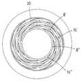
Translated fromKorean도 1 : 본 발명의 횡단면 구성도1: Cross-sectional configuration diagram of the present invention
도 2 : 본 발명의 종단면 구성도2 is a longitudinal cross-sectional view of the present invention
도 3 : 본 발명 다른 실시예의 횡단면 구성도3 is a cross-sectional view of another embodiment of the present invention
도 4 : 본 발명 다른 실시예의 종단면 구성도4 is a longitudinal cross-sectional view of another embodiment of the present invention
도 5 : 종래 발명의 횡단면 구성도5 is a cross-sectional configuration of the conventional invention
<도면의 주요부분에 대한 부호의 설명><Description of the symbols for the main parts of the drawings>
(2)(4)--이송관(6)--벨로우즈(Bellows)(2) (4)-Conveyor (6)-Bellows
(8)--슬리브(Sleeve)(10)(12)--단열재(8)-Sleeve (10) (12)-Insulation
(14)--폐쇄용 로프(16)--스틸와이어(14)-close rope (16)-steel wire
(18)(20)--단관(18) (20)-Canon
본 발명은 주로 이송관을 통한 유채의 이송시 온도변화에 의한 이송관의 과중한 응력을 흡수하는 익스팬션 죠인트(Expansion Joints)에 관한 것이다.The present invention mainly relates to expansion joints (abstraction joints) for absorbing the heavy stress of the transfer pipe due to the temperature change during the transfer of the rapeseed through the transfer pipe.
가스나 원유, 물 그리고 스팀 등을 이송하는 각종 이송관들은 외부온도나 유 체의 온도변화에 의한 배관의 팽창과 수축 그리고 기기의 진동과 풍압 및 지진 등에 의해 이송관에 가해지는 과도한 응력을 흡수하여 배관시스템 유지하는데 익스팬션죠인트가 널리 이용되고 있다.Various transfer pipes that transfer gas, crude oil, water, steam, etc. absorb excessive stress applied to the transfer pipes by expansion and contraction of pipes due to external temperature or fluid temperature change, and vibration, wind pressure and earthquake of equipment. Expansion joints are widely used to maintain piping systems.
이러한 익스팬션 죠인트로서 요구되는 조건은 벨로우즈(Bellows)가 흡수해야하는 변위량이나 변위가 작용할 경우 발생하는 신축반력의 제한에 의해 산의 갯수가 결정되어야하고 또 벨로우즈는 이송관의 사용압력과 설계압력에 견딜 수 있도록 충분한 강성을 유지함과 동시에 이송관의 변위를 흡수할 수 있는 유연성이 요구되며 더 나아가 고온하에서 열 영향에 의한 약한 벨로우즈의 수명단축 방지를 위한 단열성이 요구된다.The conditions required for such expansion joints should be determined by the amount of displacement that the bellows must absorb or by the limit of the elastic reaction force that occurs when the displacement is applied, and the bellows can withstand the operating and design pressure of the feed pipe. In order to maintain sufficient rigidity, flexibility to absorb the displacement of the transfer pipe is required, and furthermore, insulation is required to prevent shortening of the life of the weak bellows due to heat effects under high temperature.
도 5는 이제껏 일반적으로 이용되어오고 있는 익스팬션 죠인트의 단면구성도로서, 전후 이송관(50)(52) 사이에 유연성을 얻기 위하여 얇은 두께의 스틸로 제작되는 벨로우즈(54)를 연결하고 그 내측에 이송관 내경보다 작은 직경의 슬리브(Sleeve)(56)를 삽입하여 그 일단은 전방 파이프에 용접이음하고 그 타단과 후방 이송관 사이에는 적정 간격을 유지하도록 하여 그 입구를 통하여 내부에 단열재(58)를 충진하고 입구는 폐쇄용 로프(60)를 빙 둘러서 긴밀히 삽입하여 벨로우즈의 신축작용이 용이하도록 하면서 충진된 단열재의 유출이 방지되도록 구성되어 있다.5 is a cross-sectional configuration diagram of an expansion joint that has been generally used. The
따라서 이론상으로는 익스팬션 죠인트로서 요구되는 모든 조건들을 만족시켜줄 수 있는 것이라 하겠으나 실 적용시 고압하에서 유체의 이송시 발생되는 강한 흡입력이나 벨로우즈의 신축작용에 의한 움직임발생 등으로 인하여 입구측에 삽입된 로프는 물론 내부에 충진된 단열재는 점차 손실되어 이송관의 수명을 다하기 훨 씬 전 완전한 손실을 가져오게 되므로 결국 유연성을 위하여 두께가 얇은 철판으로 형성되는 벨로우즈는 직접적으로 가해지는 고열에 의해 큰 폭의 신축작용을 반복하는 과정에서 크랙이 발생되어 누유로 유체의 손실을 가져오게 됨은 물론 주위환경을 오염시키게 된다.Therefore, theoretically, it can satisfy all the conditions required as expansion joints, but the rope inserted at the inlet side due to the strong suction force generated during the transfer of fluid under high pressure during the application of the seal or the movement caused by the elasticity of the bellows, of course, As the insulation filled inside is gradually lost, it causes a complete loss much before the life of the conveying pipe. Therefore, the bellows, which is formed of a thin steel plate for flexibility, is greatly stretched by the direct heat applied. Cracks are generated in the process of repeating the process, resulting in fluid loss due to leakage, as well as polluting the surrounding environment.
특히 벨로우즈의 크랙발생시에는 교체가 전혀 불가능하여 보수를 요하게 되는데 보수시에는 단열재의 재충전은 전혀 기대할 수가 없을 뿐 아니라 밴드 등을 이용하여 크랙발생 부위를 차단해주는 것으로 만족하게 되는데 이때 돌출부는 그나마 수리가 쉽게 이루어지게 되나 요입부는 수리에 많은 어려움이 따르게 되고 또 그에 따른 수리 비용부담과 작업의 어려움에도 불구하고 이는 임시방편에 불과하여 계속되는 고열에 의한 벨로우즈의 신축작용으로 타부위에도 크랙이 발생되므로 유지보수 비용부담이 매우 클 수밖에 없으며 수리에도 한계가 있어 급속한 수명 단축을 가져와 배관시스템의 전면 교체기간을 앞당기게 되므로 그에 따른 금전적 손실도 더해지게 되는 등의 많은 문제점들이 있는 것이다.Especially in case of crack of bellows, it is impossible to replace it at all and repair is not necessary. When repairing, it is not possible to expect recharging of the insulation at all, and it is satisfied that the crack is cut off by using bands. However, the main part is difficult to repair, and despite the cost of repair and labor, this is only a temporary measure, and it is a temporary solution, so the cracking occurs in other parts due to the continuous expansion of the bellows due to continuous heat. This is very large and there are limitations in repairing, which leads to a rapid shortening of life, which leads to a faster front replacement period of the piping system, and thus there are many problems such as financial loss.
본 발명은 상술한 종래 기술이 갖는 문제점들을 해결하기 위하여 배관의 수명이 다할 때까지 단열성을 유지해줄 수가 있어 고열에 의한 벨로우즈의 파손방지로 유체의 손실과 주위환경을 오염시킬 우려가 없으며 특히 파손으로 인한 유지보수 비용을 줄일 수가 있고 배관의 수명보장으로 결과적으로 배관의 전면교체비용까지도 줄일 수가 있는 익스팬션 죠인트를 제공하고자 한다.The present invention can maintain the thermal insulation until the life of the pipe to solve the problems of the prior art described above, there is no risk of polluting the fluid and the surrounding environment by preventing the bellows breakage due to high heat, especially the breakage The company aims to provide expansion joints that can reduce maintenance costs and ensure the life of the pipes, which in turn can reduce the cost of pipe replacement.
상기한 본 발명의 목적은 벨로우즈와 슬리브 사이에 충전된 단열재와 그 입구에 삽입된 폐쇄용 로프가 그 외측에 형성되는 다수의 스틸와이어에 의해 지체배출되게 하고, 슬리브 내측에는 입구방향을 달리하는 다른 수개의 슬리브를 형성하여 이역시 그사이에 충진된 단열재와 입구에 끼워진 폐쇄용 로프가 스틸와이어에 의해 지체배출되게 한 익스팬션 죠인트에 의해 달성된다.The object of the present invention described above is to allow the insulation filled between the bellows and the sleeve and the closing rope inserted into the inlet to be delayed by a plurality of steel wires formed on the outside thereof, and to change the inlet direction inside the sleeve. This is achieved by expansion joints, which form several sleeves, which in turn allow the thermal insulation filled between them and the closing rope fitted to the inlet to be retarded by the steel wires.
도 1 및 도 2는 본발명의 단면구성도로서, 본 발명은 전후 이송관(2)(4) 사이에 벨로우즈(Bellows)(6)가 용접이음되고, 상기 벨로우즈 내측에는 이송관의 내경보다 작은 직경의 원통형 슬리브(Sleeve)(8)가 삽입되어 그 일단은 전방 이송관(2)에 용접이음되고 벨로우즈(6)와 슬리브(8) 사이에 갖는 공간부내에는 유리섬유로 이루어진 단열재(10)(12)가 충진되고, 단열재의 충진후 후방 이송관(4)과 슬리브(8)의 타단 사이에 갖는 입구에는 폐쇄용 로프(14)가 긴밀히 삽입되며, 상기 폐쇄용 로프(14) 외측에는 그 일단이 슬리브(8)에 용접고정되고 타단은 탄성을 갖고 후방 이송관(4)과 밀접하는 두 개 이상의 스틸와이어(16)가 형성된다.1 and 2 is a cross-sectional view of the present invention, the present invention is a bellows (6) is welded between the front and rear transfer pipe (2) (4), the inside of the bellows is smaller than the inner diameter of the transfer pipe A cylindrical sleeve (8) of diameter is inserted, one end of which is welded to the front feed pipe (2) and insulated from the bellows (6) and the sleeve (8) by an insulating material (10) made of glass fiber ( 12) is filled, and the
상기에 있어 벨로우즈(6)와 슬리브(8) 사이의 공간부에 충진되는 단열재는 전체적으로 충진시기를 같이 할 수도 있으나 벨로우즈의 돌출부 내측에 갖는 깊숙한 공간부와 그외의 얕은 공간부를 구분하여 충진해 주는 것이 바람직하며, 이러한 경우 유출시간을 다소나마 지연시켜주는 역할을 하게 된다.In the above, the heat insulating material filled in the space portion between the
또한 스틸와이어는 슬리브가 아닌 이송관에 용접고정되게하여 타단이 슬리브와 탄성을 갖고 접촉되게 하더라도 무방하고 또 그 갯수를 한정하지않고 두개이상으로서 그 입구를 차단토록 한 것이면 만족하나 갯수가 많을수록 유리하고, 더나아가 이송관과 슬리브 사이에 갖는 간격보다 길게 형성하여 각기 주어진 방향으로 휘어져 탄성이 주어지도록 하는 것이 바람직하다.In addition, the steel wire is welded and fixed to the conveying pipe, not the sleeve, so that the other end may be elastically in contact with the sleeve, and the number of the two wires is not limited and the number is satisfied. Further, it is preferable to form longer than the gap between the conveying pipe and the sleeve so that each is bent in a given direction to give elasticity.
도 3 및 도 4는 본 발명의 다른 실시예로서, 벨로우즈(6') 내측에 슬리브(8')를 여러겹으로 형성해줄 수도 있음을 보여주고 있다.3 and 4 show that as another embodiment of the present invention, the sleeve 8 'may be formed in multiple layers inside the bellows 6'.
이때 각 슬리브(8')(8")는 이송관(2')(4')측에 용접고정되게 하면서 그 입구는 서로간에 방향을 달리하도록 하고 또 외측 슬리브와의 사이에 갖도록 하여 내측 슬리브(8")를 제외한 슬리브(8')의 입구는 공간부내에 위치하도록 하며, 유로를 갖는 내측 슬리브(8")의 입구는 유체의 흐름 반대방향에 갖도록 하는 것이 바람직하다.At this time, each sleeve (8 '), 8 "is welded to the side of the conveying pipe (2'), 4 'side while the inlet is different from each other and between the outer sleeve and the inner sleeve ( The inlet of the sleeve 8 'except 8 " is preferably located in the space and the inlet of the
이 역시 각기 외측 슬리브와의 사이에 갖는 공간부에는 단열재(12')(12")가 충진되고 그 입구에는 폐쇄용 로프(14')(14")를 삽입한 다음 폐쇄용 로프 외측에 스틸와이어(16')(16")를 용접형성하여 폐쇄용 로프(14')(14")와 단열재(12')(12")의 유출이 지체되도록 구성된다.This is also filled with
다만 슬리브(8')(8")가 다단으로 형성되는 경우 상기 슬리브를 파이프에 용접고정하게 되면 이용되는 슬리브의 갯수가 증가할수록 그 내측 슬리브가 갖게 되는 유로는 이송관(2')(4')이 갖는 유로보다 훨씬 작아지게 되어 유체의 흐름을 크게 방해하게 되므로 이러한 경우 전후 이송관(2')(4') 단부에 이송관 직경보다 큰 직경의 연결용 단관(18)(20)을 연결형성하여 상기 단관(18)(20)을 통하여 연결해주는 것이 바람직하다.However, when the
본 발명은 파이프 라인을 통한 유체의 이송시 이송관(4)과 슬리브(8) 사이의 입구측에 갖는 수개의 스틸와이어(16)는 그 일단이 슬리브(8)에 용접고정되고 타단은 탄성을 갖고 이송관(4)과 접촉하게 되므로 벨로우즈(6)의 신축작용을 방해하지 않으면서 고압하여서 이루어지는 유체의 이송시 유체의 흐름에 의해 그 입구를 차단하고 있는 폐쇄용 로프(14)에 큰 흡입력이 작용하게 되더라도 상기 폐쇄용 로프(14) 외측에 갖는 수개의 스틸와이어(16)가 폐쇄용 로프(14)의 급속한 이탈을 방지해주게 되므로 폐쇄용 로프(14)와 단열재(10)(12)의 손실시간을 연장하여 단열재의 수명을 늘려줄 수가 있게 된다.According to the present invention,
그리고 본 발명은 슬리브(8')(8")를 다단으로 형성하면서 슬리브 사이사이에도 단열재(12')(12")를 충진하고 입구에 폐쇄용 로프(14')(14")를 삽입하여 이들 역시 스틸와이어(16')(16")에 의해 차단되게 하면 유체의 흐름에 의해 벨로우즈와 슬리브 사이에 갖는 단열재가 완전 유출되기까지에는 그만큼 더 많은 기간을 필요로 하게 되므로 파이프의 수명보다 더욱 긴 수명을 갖게 되는 것이다.In the present invention, the
이와 같이 본 발명은 유체의 이송시 작용하는 강한 흡입력에도 불구하고 폐쇄용 로프 외측에 갖는 다수의 스틸와이어(16)가 폐쇄용 로프(14)를 지지하여 폐쇄용 로프(14)와 단열재(10)(12)의 손실을 최대한 억제시켜 주게 되므로 단열재의 수명이 연장되는 만큼 벨로우즈(6)의 수명연장을 가져와 벨로우즈의 크랙발생으로 인한 유체의 손실과 누유로 인한 환경오염을 방지해줄 수가 있고 또 유지보수비용을 절감할 수가 있게 됨은 물론 파이프라인의 수명보장으로 교체비용을 줄일 수가 있게 되는 등의 효과가 있는 것이다.Thus, in the present invention, despite the strong suction force acting upon the transfer of fluid, a plurality of
Claims (4)
Translated fromKoreanPriority Applications (1)
| Application Number | Priority Date | Filing Date | Title |
|---|---|---|---|
| KR1020050096106AKR100692965B1 (en) | 2005-10-12 | 2005-10-12 | Expansion joint |
Applications Claiming Priority (1)
| Application Number | Priority Date | Filing Date | Title |
|---|---|---|---|
| KR1020050096106AKR100692965B1 (en) | 2005-10-12 | 2005-10-12 | Expansion joint |
Publications (1)
| Publication Number | Publication Date |
|---|---|
| KR100692965B1true KR100692965B1 (en) | 2007-03-12 |
Family
ID=38103122
Family Applications (1)
| Application Number | Title | Priority Date | Filing Date |
|---|---|---|---|
| KR1020050096106AExpired - Fee RelatedKR100692965B1 (en) | 2005-10-12 | 2005-10-12 | Expansion joint |
Country Status (1)
| Country | Link |
|---|---|
| KR (1) | KR100692965B1 (en) |
Cited By (2)
| Publication number | Priority date | Publication date | Assignee | Title |
|---|---|---|---|---|
| KR20200116367A (en)* | 2019-04-01 | 2020-10-12 | 엔이에스 주식회사 | Bellows of LNG bunkering device for low temperature use |
| CN114413097A (en)* | 2021-12-09 | 2022-04-29 | 洛阳双瑞特种装备有限公司 | High-temperature expansion joint with vibration-proof and heat-insulation structure |
Citations (4)
| Publication number | Priority date | Publication date | Assignee | Title |
|---|---|---|---|---|
| JPS5196615U (en) | 1975-01-31 | 1976-08-03 | ||
| JPS5265320U (en) | 1975-11-11 | 1977-05-14 | ||
| US4047740A (en) | 1976-06-01 | 1977-09-13 | Caterpillar Tractor Co. | Internally insulated bellows assembly |
| JPH07224982A (en)* | 1994-02-14 | 1995-08-22 | Calsonic Corp | Flexible tube |
- 2005
- 2005-10-12KRKR1020050096106Apatent/KR100692965B1/ennot_activeExpired - Fee Related
Patent Citations (4)
| Publication number | Priority date | Publication date | Assignee | Title |
|---|---|---|---|---|
| JPS5196615U (en) | 1975-01-31 | 1976-08-03 | ||
| JPS5265320U (en) | 1975-11-11 | 1977-05-14 | ||
| US4047740A (en) | 1976-06-01 | 1977-09-13 | Caterpillar Tractor Co. | Internally insulated bellows assembly |
| JPH07224982A (en)* | 1994-02-14 | 1995-08-22 | Calsonic Corp | Flexible tube |
Cited By (4)
| Publication number | Priority date | Publication date | Assignee | Title |
|---|---|---|---|---|
| KR20200116367A (en)* | 2019-04-01 | 2020-10-12 | 엔이에스 주식회사 | Bellows of LNG bunkering device for low temperature use |
| KR102275157B1 (en)* | 2019-04-01 | 2021-07-08 | 엔이에스 주식회사 | Bellows of LNG bunkering device for low temperature use |
| CN114413097A (en)* | 2021-12-09 | 2022-04-29 | 洛阳双瑞特种装备有限公司 | High-temperature expansion joint with vibration-proof and heat-insulation structure |
| CN114413097B (en)* | 2021-12-09 | 2023-11-17 | 中船双瑞(洛阳)特种装备股份有限公司 | High-temperature expansion joint with vibration-proof heat-insulating structure |
Similar Documents
| Publication | Publication Date | Title |
|---|---|---|
| FI72590B (en) | HOEG TEMPERATUR ISOLERANDE MANTEL. | |
| US10577871B2 (en) | Subsea pipe-in-pipe structures | |
| JP4890617B2 (en) | System for dynamically sealing at least one conduit through which a pipe or cable extends | |
| JP5346067B2 (en) | A system for dynamically sealing a conduit sleeve into which a pipe or cable is inserted | |
| AU778864B2 (en) | Radial partition device, in particular radial buckle arrestor for a double-walled deep water pipeline | |
| JP2006038223A (en) | Seal for pipe device | |
| US3246917A (en) | Flexible diaphragm type conduit seal | |
| NO335648B1 (en) | Pipeline installation under water | |
| KR101327446B1 (en) | Connecting tube | |
| KR100692965B1 (en) | Expansion joint | |
| BR112012000974A2 (en) | SET OF COAXIA TUBES UNDERSTANDING JUNCTION PIECES WITH SEALED INTERNAL CAVITIES AND EXECUTION METHODS | |
| BRPI0513734B1 (en) | Set of at least two coaxial conduits and process of making this set | |
| KR20090010479A (en) | Pipe connector | |
| RU2395029C1 (en) | Permanent connection of pipes with internal anti-corrosion coating | |
| KR20090093356A (en) | Hot water pipe of double pipe structure | |
| KR20110040001A (en) | Replacement piping | |
| JP2019128039A (en) | Bellows seal for pipe penetrating through floor or wall | |
| EP1857725B1 (en) | Insulation of pipe-in-pipe systems | |
| KR100665208B1 (en) | Connector | |
| KR101379005B1 (en) | Pipeline | |
| US11306848B2 (en) | Method for assembling pipe-in-pipe pipeline elements for transporting fluids | |
| RU2676548C1 (en) | Internal insert for sealing welded joint of pipeline | |
| CN109798405A (en) | Profound hypothermia pressure compensation type hermetic collar | |
| KR100535707B1 (en) | Double pipe for high pressure and temperature | |
| CN105443898A (en) | Pipeline joint device with anti-shock deformation compatibility capacity |
Legal Events
| Date | Code | Title | Description |
|---|---|---|---|
| A201 | Request for examination | ||
| PA0109 | Patent application | St.27 status event code:A-0-1-A10-A12-nap-PA0109 | |
| PA0201 | Request for examination | St.27 status event code:A-1-2-D10-D11-exm-PA0201 | |
| P11-X000 | Amendment of application requested | St.27 status event code:A-2-2-P10-P11-nap-X000 | |
| P13-X000 | Application amended | St.27 status event code:A-2-2-P10-P13-nap-X000 | |
| D13-X000 | Search requested | St.27 status event code:A-1-2-D10-D13-srh-X000 | |
| R17-X000 | Change to representative recorded | St.27 status event code:A-3-3-R10-R17-oth-X000 | |
| D14-X000 | Search report completed | St.27 status event code:A-1-2-D10-D14-srh-X000 | |
| PN2301 | Change of applicant | St.27 status event code:A-3-3-R10-R13-asn-PN2301 St.27 status event code:A-3-3-R10-R11-asn-PN2301 | |
| E902 | Notification of reason for refusal | ||
| PE0902 | Notice of grounds for rejection | St.27 status event code:A-1-2-D10-D21-exm-PE0902 | |
| P11-X000 | Amendment of application requested | St.27 status event code:A-2-2-P10-P11-nap-X000 | |
| P13-X000 | Application amended | St.27 status event code:A-2-2-P10-P13-nap-X000 | |
| E701 | Decision to grant or registration of patent right | ||
| PE0701 | Decision of registration | St.27 status event code:A-1-2-D10-D22-exm-PE0701 | |
| GRNT | Written decision to grant | ||
| PR0701 | Registration of establishment | St.27 status event code:A-2-4-F10-F11-exm-PR0701 | |
| PR1002 | Payment of registration fee | St.27 status event code:A-2-2-U10-U11-oth-PR1002 Fee payment year number:1 | |
| PG1601 | Publication of registration | St.27 status event code:A-4-4-Q10-Q13-nap-PG1601 | |
| PR1001 | Payment of annual fee | St.27 status event code:A-4-4-U10-U11-oth-PR1001 Fee payment year number:4 | |
| FPAY | Annual fee payment | Payment date:20110303 Year of fee payment:5 | |
| PR1001 | Payment of annual fee | St.27 status event code:A-4-4-U10-U11-oth-PR1001 Fee payment year number:5 | |
| LAPS | Lapse due to unpaid annual fee | ||
| PC1903 | Unpaid annual fee | St.27 status event code:A-4-4-U10-U13-oth-PC1903 Not in force date:20120306 Payment event data comment text:Termination Category : DEFAULT_OF_REGISTRATION_FEE | |
| R18-X000 | Changes to party contact information recorded | St.27 status event code:A-5-5-R10-R18-oth-X000 | |
| PC1903 | Unpaid annual fee | St.27 status event code:N-4-6-H10-H13-oth-PC1903 Ip right cessation event data comment text:Termination Category : DEFAULT_OF_REGISTRATION_FEE Not in force date:20120306 | |
| P22-X000 | Classification modified | St.27 status event code:A-4-4-P10-P22-nap-X000 |