KR100692897B1 - Mobile robot - Google Patents
Mobile robotDownload PDFInfo
- Publication number
- KR100692897B1 KR100692897B1KR1020050102517AKR20050102517AKR100692897B1KR 100692897 B1KR100692897 B1KR 100692897B1KR 1020050102517 AKR1020050102517 AKR 1020050102517AKR 20050102517 AKR20050102517 AKR 20050102517AKR 100692897 B1KR100692897 B1KR 100692897B1
- Authority
- KR
- South Korea
- Prior art keywords
- signal
- charging station
- mobile robot
- guide
- sensor
- Prior art date
- Legal status (The legal status is an assumption and is not a legal conclusion. Google has not performed a legal analysis and makes no representation as to the accuracy of the status listed.)
- Expired - Fee Related
Links
Images


Classifications
- G—PHYSICS
- G05—CONTROLLING; REGULATING
- G05D—SYSTEMS FOR CONTROLLING OR REGULATING NON-ELECTRIC VARIABLES
- G05D1/00—Control of position, course, altitude or attitude of land, water, air or space vehicles, e.g. using automatic pilots
- G05D1/02—Control of position or course in two dimensions
- G05D1/021—Control of position or course in two dimensions specially adapted to land vehicles
- G05D1/0212—Control of position or course in two dimensions specially adapted to land vehicles with means for defining a desired trajectory
- G05D1/0225—Control of position or course in two dimensions specially adapted to land vehicles with means for defining a desired trajectory involving docking at a fixed facility, e.g. base station or loading bay
- G—PHYSICS
- G05—CONTROLLING; REGULATING
- G05D—SYSTEMS FOR CONTROLLING OR REGULATING NON-ELECTRIC VARIABLES
- G05D1/00—Control of position, course, altitude or attitude of land, water, air or space vehicles, e.g. using automatic pilots
- G05D1/02—Control of position or course in two dimensions
- G05D1/021—Control of position or course in two dimensions specially adapted to land vehicles
- G05D1/0231—Control of position or course in two dimensions specially adapted to land vehicles using optical position detecting means
- G05D1/0242—Control of position or course in two dimensions specially adapted to land vehicles using optical position detecting means using non-visible light signals, e.g. IR or UV signals
- B—PERFORMING OPERATIONS; TRANSPORTING
- B25—HAND TOOLS; PORTABLE POWER-DRIVEN TOOLS; MANIPULATORS
- B25J—MANIPULATORS; CHAMBERS PROVIDED WITH MANIPULATION DEVICES
- B25J11/00—Manipulators not otherwise provided for
- B25J11/008—Manipulators for service tasks
- B25J11/0085—Cleaning
- B—PERFORMING OPERATIONS; TRANSPORTING
- B25—HAND TOOLS; PORTABLE POWER-DRIVEN TOOLS; MANIPULATORS
- B25J—MANIPULATORS; CHAMBERS PROVIDED WITH MANIPULATION DEVICES
- B25J13/00—Controls for manipulators
- B25J13/08—Controls for manipulators by means of sensing devices, e.g. viewing or touching devices
- B25J13/088—Controls for manipulators by means of sensing devices, e.g. viewing or touching devices with position, velocity or acceleration sensors
- B—PERFORMING OPERATIONS; TRANSPORTING
- B25—HAND TOOLS; PORTABLE POWER-DRIVEN TOOLS; MANIPULATORS
- B25J—MANIPULATORS; CHAMBERS PROVIDED WITH MANIPULATION DEVICES
- B25J19/00—Accessories fitted to manipulators, e.g. for monitoring, for viewing; Safety devices combined with or specially adapted for use in connection with manipulators
- B25J19/005—Accessories fitted to manipulators, e.g. for monitoring, for viewing; Safety devices combined with or specially adapted for use in connection with manipulators using batteries, e.g. as a back-up power source
- B—PERFORMING OPERATIONS; TRANSPORTING
- B25—HAND TOOLS; PORTABLE POWER-DRIVEN TOOLS; MANIPULATORS
- B25J—MANIPULATORS; CHAMBERS PROVIDED WITH MANIPULATION DEVICES
- B25J19/00—Accessories fitted to manipulators, e.g. for monitoring, for viewing; Safety devices combined with or specially adapted for use in connection with manipulators
- B25J19/02—Sensing devices
- A—HUMAN NECESSITIES
- A47—FURNITURE; DOMESTIC ARTICLES OR APPLIANCES; COFFEE MILLS; SPICE MILLS; SUCTION CLEANERS IN GENERAL
- A47L—DOMESTIC WASHING OR CLEANING; SUCTION CLEANERS IN GENERAL
- A47L2201/00—Robotic cleaning machines, i.e. with automatic control of the travelling movement or the cleaning operation
- A47L2201/02—Docking stations; Docking operations
- A47L2201/022—Recharging of batteries
Landscapes
- Engineering & Computer Science (AREA)
- Physics & Mathematics (AREA)
- General Physics & Mathematics (AREA)
- Aviation & Aerospace Engineering (AREA)
- Radar, Positioning & Navigation (AREA)
- Remote Sensing (AREA)
- Automation & Control Theory (AREA)
- Mechanical Engineering (AREA)
- Robotics (AREA)
- Electromagnetism (AREA)
- Human Computer Interaction (AREA)
- Control Of Position, Course, Altitude, Or Attitude Of Moving Bodies (AREA)
- Manipulator (AREA)
- Electric Vacuum Cleaner (AREA)
Abstract
Translated fromKoreanDescription
Translated fromKorean도 1은 본 발명의 바람직한 일 실시 예에 따른 이동로봇을 이용한 충전대 복귀 시스템을 개략적으로 도시한 개요도이다.1 is a schematic diagram schematically showing a charging station return system using a mobile robot according to an embodiment of the present invention.
도 2는 본 발명의 바람직한 일 실시 예에 따른 이동로봇의 일례인 청소로봇을 개략적으로 도시한 블럭도이다.Figure 2 is a block diagram schematically showing a cleaning robot as an example of a mobile robot according to an embodiment of the present invention.
도 3은 본 발명의 바람직한 일 실시 예에 따른 이동로봇에 구비되는 감지센서의 위치를 나타낸 개요도이다.Figure 3 is a schematic diagram showing the position of the detection sensor provided in the mobile robot according to an embodiment of the present invention.
도 4는 본 발명의 또 다른 실시 예에 따른 이동로봇에 구비되는 감지센서의 위치를 나타낸 개요도이다.Figure 4 is a schematic diagram showing the position of the detection sensor provided in the mobile robot according to another embodiment of the present invention.
도 5는 본 발명의 또 다른 실시 예에 따른 이동로봇에 구비되는 감지센서의 위치를 나타낸 개요도이다.Figure 5 is a schematic diagram showing the position of the detection sensor provided in the mobile robot according to another embodiment of the present invention.
본 발명은 이동로봇에 관한 것으로 보다 상세하게는 충전대로부터 발신되는 안내신호를 수신하는 다수의 감지센서를 이동로봇에 구비하여 보다 정확한 충전대의 위치를 산출하고 산출된 위치를 참조하여 효과적으로 복귀할 수 있는 이동로봇 충전대 복귀 기술에 관한 것이다.The present invention relates to a mobile robot, and more particularly, the mobile robot includes a plurality of sensing sensors that receive guide signals from a charging station, thereby calculating a more accurate position of the charging station and effectively returning the mobile terminal with reference to the calculated position. Mobile robot charging station return technology.
로봇은 산업용으로 개발되어 공장 자동화의 일환으로 사용되거나, 인간이 견딜 수 없는 극한의 환경에서 인간을 대신하여 정보를 수집하거나 채집하는데 사용되어 왔다. 이러한 로봇공학 분야는 근래에 들어 최첨단 우주개발산업에 사용되면서 발전을 거듭하여 왔고, 최근에 들어서는 인간 친화적인 가정용 로봇이 개발되기에 까지 이르렀다. 이러한 인간 친화적인 가정용 로봇의 대표적인 예가 바로 청소로봇이다.Robots have been developed for industrial use and as part of factory automation, or have been used to collect or collect information on behalf of humans in extreme environments that humans cannot tolerate. This field of robotics has been developed in recent years as it is used in the cutting-edge space development industry, and until recently, human-friendly home robots have been developed. A representative example of such a human-friendly home robot is a cleaning robot.
이동로봇의 하나인 청소로봇은 주택 또는 사무실과 같은 일정한 청소구역을 스스로 구동하면서, 먼지 또는 이물질을 흡입하는 기기이다. 이 같은 청소로봇은 먼지 또는 이물질을 흡입하는 일반적인 진공 청소기의 구성 이외에 해당 청소로봇을 주행시키는 우륜 및 좌륜모터를 포함하는 주행수단과, 청소구역 내에 있는 다양한 장애물과 충돌하지 않고 주행할 수 있도록 다수의 감지센서와, 장치 전반을 제어하는 제어부 등으로 구성되어 있다.A cleaning robot, a mobile robot, is a device that inhales dust or foreign substances while driving itself in a certain cleaning area such as a house or an office. In addition to the configuration of a general vacuum cleaner that sucks in dust or foreign matter, such a cleaning robot includes a driving means including a right wheel and a left wheel motor for driving the cleaning robot, and a plurality of driving means for driving without colliding with various obstacles in the cleaning area. It is composed of a sensor and a control unit for controlling the overall device.
한편, 이동로봇은 정해진 구역을 스스로 이동하며 임무를 수행하기 때문에 자동 충전 기능을 가지고 있다. 자동 충전기능은 이동로봇 스스로 배터리의 잔량을 파악하여 기준 값에 이르지 못할 경우 임무 수행 구역의 소정 위치에 설치된 충전대에 자동으로 복귀하여 부족한 배터리의 전원을 충전하고, 다시 작업을 재개한다.On the other hand, the mobile robot has an automatic charging function because it performs a mission by moving itself in a predetermined area. The automatic charging function automatically detects the remaining battery level of the mobile robot and automatically returns to the charging station installed at a predetermined position in the mission area when the mobile robot does not reach the reference value.
그러나 종래의 이동로봇의 충전대 자동 복귀 방법은 충전대에 인공표식을 부착하고, 이동로봇이 임무수행 구역의 벽면을 따라 랜덤주행을 통해 충전대에 부착 된 표식을 감지하게 함으로써 충전대의 위치를 판단하고 복귀시키는 방법이다.However, in the conventional method of automatically returning the charging stand of the mobile robot, an artificial mark is attached to the charging stand, and the mobile robot detects the position of the charging stand by detecting the mark attached to the charging stand through random driving along the wall of the mission area. Way.
그러나 이와 같은 방법은 이동로봇의 벽면을 따라 랜덤주행에 의한 것이므로, 이동로봇이 위치한 지역에 따라 충전대로 복귀하는 시간이 달라진다. 이러한 벽면 랜덤주행 방식의 충전대 복귀 방법은 충전대에 부착된 인공표식을 감지하기 위한 시간이 길어질 경우 복귀중에 배터리에 저장된 전원이 모두 감소하여 그 구동을 중지하는 문제점을 가지고 있다.However, since this method is caused by random driving along the wall of the mobile robot, the time to return to the charging station varies according to the area where the mobile robot is located. The charging method of the random charging method of the wall random driving method has a problem in that when the time for detecting the artificial mark attached to the charging table becomes long, the power stored in the battery decreases during the recovery and the driving thereof is stopped.
또 다른 방법으로 충전대에 단일 파장의 적외선 또는 초음파를 발산하는 신호발신 수단을 설치하고, 이동로봇이 소정 영역에서만 수신되는 신호를 감지하여 해당 충전대로 복귀하는 방법이 있다.As another method, there is a method of installing a signal transmitting means for emitting infrared rays or ultrasonic waves of a single wavelength in the charging station, and detecting the signal received only in a predetermined area by the mobile robot to return to the charging station.
그러나 이와 같은 방법은 충전대로부터 발산되는 단일 파장의 신호를 수신하여 충전대의 방향만을 산출하기 때문에 충전대가 위치한 방향은 감지할 수는 있으나, 충전대로의 정확한 도킹을 위한 최적 경로로의 접근 정도를 알 수 없기 때문에 충전대와의 기구적 또는 전기적인 접촉이 일어나기까지 충전대 복귀 경로를 변경하기 힘든 단점이 있다.However, this method can detect the direction of the charging station because it receives a single wavelength signal from the charging station and calculates only the direction of the charging station.However, it is possible to know the degree of access to the optimal path for accurate docking of the charging station. There is a disadvantage that it is difficult to change the charging station return path until mechanical or electrical contact with the charging station occurs.
또한, 종래의 이동로봇은 장애물을 감지하는 감지센서와 충전대의 위치를 감지하기 위한 감지센서를 각각 별도로 구비하였다. 따라서 두 가지 용도의 감지센서를 이동로봇에 설치해야 함으로써, 감지센서의 수량 증가와 그 설치를 위한 공간적인 제약, 구동 회로의 증가와 같은 문제점이 있어 이동로봇 설계에 많은 제약을 주는 단점이 있다.In addition, the conventional mobile robot is provided with a separate sensor for detecting the obstacle and a sensor for detecting the position of the charging stand. Therefore, there are problems such as the increase in the number of sensors and the spatial constraints for the installation, the increase of the driving circuit, there are many limitations in the design of the mobile robot by having to install a sensor for two uses in the mobile robot.
본 발명은 이와 같은 문제점을 해결하기 위해 창안된 것으로, 그 목적은 충 전대 안내신호와 장애물 감지신호의 주파수 대역을 달리하여 충전대 안내신호와 장애물 감지를 위한 감지신호의 센서를 공용화하여 이동로봇의 구조를 단순화한 이동로봇을 제공하는 데 있다.The present invention was devised to solve such a problem, and its purpose is to change the frequency band of the charging guide guide signal and the obstacle detection signal to share the sensor of the charging guide guide signal and the detection signal for obstacle detection structure of the mobile robot. To provide a simplified mobile robot.
상술한 본 발명의 일 양상에 따른 서로 다른 주파수 대역을 갖는 장애물 감지신호와 충전대로부터 발산되는 안내신호를 수신하는 하나 이상의 감지센서를 포함하는 신호 수신부와, 임무 수행 공간을 주행하기 위한 주행수단과, 소정 주기마다 구동 전원을 공급하는 배터리의 잔량을 감지하여 그 값이 소정 값 이하일 경우 배터리 충전 요청 신호를 출력하는 배터리 감지회로와, 배터리 감지회로로부터 출력되는 배터리 충전 요청 신호에 따라 신호 수신부로부터 출력되는 안내신호와 장애물 감지신호의 상이한 주파수 대역을 이용하여 충전대 안내신호를 검색하고, 검색한 안내신호를 이용하여 충전대의 위치를 판단하고 충전대로 복귀하도록 주행 수단으로 제어신호를 출력하는 제어부를 포함한다.A signal receiving unit including at least one sensing sensor configured to receive obstacle detection signals having different frequency bands and guide signals emitted from a charging station according to an aspect of the present invention, traveling means for driving a mission performing space; A battery detection circuit that detects a residual amount of battery for supplying driving power every predetermined period and outputs a battery charge request signal when the value is less than a predetermined value, and is output from a signal receiver according to a battery charge request signal output from the battery detection circuit. And a control unit for searching the charging station guide signal using different frequency bands of the guide signal and the obstacle detection signal, and outputting a control signal to the traveling means to determine the position of the charging station using the searched guide signal and return to the charging station.
따라서, 이동로봇은 장애물을 감지신호와 충전대로부터 출력되는 안내신호를 동시에 수신할 수 있는 감지센서를 이동로봇에 다수 개 형성하고, 수신되는 신호의 주파수를 이용하여 분류 처리함으로써, 이동로봇의 장애물 회피 주행 및 충전대 복귀를 효과적으로 처리할 수 있다.Therefore, the mobile robot forms a plurality of detection sensors on the mobile robot that can simultaneously receive obstacle detection signals and guide signals output from the charging station, and classifies the received signals using frequencies of the received signals, thereby avoiding obstacles of the mobile robot. The driving and return to the charging station can be effectively handled.
본 발명의 또 다른 양상에 따라 본 발명에 따른 이동로봇은 장애물 감지 신호와 충전대 안내신호를 수신하는 감지센서를 공용화함으로써, 측면에 소정 간격으로 이격되게 설치되는 장애물 감지센서를 가지는 이동로봇의 구조적인 변경 없이 충전대 복귀를 처리하는 프로그램의 탑재만으로 효과적인 충전대 복귀를 가능하게 한다.According to another aspect of the present invention, the mobile robot according to the present invention by using a common detection sensor for receiving the obstacle detection signal and the charging guide guide signal, the structural structure of the mobile robot having an obstacle detection sensor spaced apart at predetermined intervals on the side Efficient charging of the charging stand is possible only by loading a program for handling the charging stand return without modification.
이하에서는 첨부된 도면을 참조로 하여 기술되는 바람직한 실시 예를 통해 본 발명을 당업자가 용이하게 이해하고 재현할 수 있도록 상세히 기술하기로 한다.Hereinafter, the present invention will be described in detail with reference to the accompanying drawings so that those skilled in the art can easily understand and reproduce the present invention.
도 1은 본 발명의 바람직한 일 실시 예에 따른 이동로봇을 이용한 충전대 복귀 시스템을 개략적으로 도시한 개요도이다. 도시된 바와 같이, 본 발명에 따른 이동로봇의 충전대 복귀 시스템은 서로 다른 신호를 각각의 영역으로 안내신호를 발산하는 하나 이상의 안내신호 발신수단을 포함하는 충전대(100)와, 충전대(100)로부터 발산되는 안내신호를 수신하여 충전대(100)의 위치정보를 산출하고, 산출된 위치정보를 통해 충전대(100)로 복귀하는 이동로봇(200)을 포함하여 구성된다.1 is a schematic diagram schematically showing a charging station return system using a mobile robot according to an embodiment of the present invention. As shown, the charging table return system of the mobile robot according to the present invention, the charging table 100 including one or more guide signal transmitting means for emitting a guide signal to each area of the different signal, and radiates from the charging table 100 Receiving the guidance signal to calculate the position information of the
충전대(100)는 이동로봇(200)을 구동하는데 필요한 전원을 공급하는 배터리를 충전한다. 이동로봇(200)이 임무수행중에 배터리의 잔량을 감지하여 충전이 필요하다고 판단되면, 충전대 복귀 알고리즘에 의해 충전대(100)로 복귀하게 된다. 충전대(100)는 충전대 복귀 알고리즘에 의해 이동로봇(200)이 도킹하면, 이동로봇(200)에 전원을 공급하고, 공급된 전원은 배터리를 충전시킨다. 충전이 종료되면, 이동로봇(200)은 충전대(100)를 이탈하여 수행중이던 임무를 재개한다.
이동로봇(200)은 탑재된 프로그램에 따라 정해진 구역을 스스로 이동하면서 임무를 수행한다. 상용화된 대표적인 예로 청소로봇(200)을 들 수 있으며, 청소로봇(200)은 정해진 구역을 자유롭게 주행하면서, 먼지 또는 이물질을 흡입하는 이동로봇(200)이다.The
본 발명에 따른 이동로봇(200)은 도 2를 통해 상세히 설명하기로 한다.The
도 2는 본 발명의 바람직한 일 실시 예에 따른 이동로봇의 일례인 청소로봇을 개략적으로 도시한 블럭도이다. 도시된 바와 같이, 본 발명의 바람직한 일 실시 예에 따른 이동로봇(200)의 한 예인 청소로봇(200)은 그 기본 구성 이외에 서로 다른 주파수 대역을 갖는 장애물 감지신호와 충전대(100)로부터 발산되는 안내신호를 수신하는 하나 이상의 감지센서(261)를 포함하는 신호 수신부(260)와, 임무 수행 공간을 주행하기 위한 주행수단(220)과, 소정 주기마다 구동 전원을 공급하는 배터리(230)의 잔량을 감지하여 그 값이 소정 값 이하일 경우 배터리 충전 요청 신호를 출력하는 배터리 감지회로(240)와, 배터리 감지회로(240)로부터 출력되는 배터리 충전 요청 신호에 따라 신호 수신부(260)로부터 출력되는 안내신호와 장애물 감지신호의 상이한 주파수 대역을 이용하여 충전대 안내신호를 검색하고, 검색한 안내신호를 이용하여 충전대(100)의 위치를 판단하고 충전대(100)로 복귀하도록 주행 수단으로 제어신호를 출력하는 제어부를 포함하여 구성된다.Figure 2 is a block diagram schematically showing a cleaning robot as an example of a mobile robot according to an embodiment of the present invention. As shown, the
청소로봇(200)의 기본 구성을 살펴보면 청소구역 내의 먼지 또는 이물질을 감지하는 먼지 감지센서를 포함하고, 먼지 감지센서에 의해 감지된 먼지 또는 이물질을 흡입하는 흡입장치(211)와, 흡입장치(211)에 의해 집진 된 먼지 및 이물질을 수납하는 먼지 수납부(212)를 포함하는 청소수단(210)과, 청소로봇(200)을 주행시키는 주행수단(220)과, 청소수단(210) 및 주행수단(220)에 구동 전원을 공급하는 배터리(230)와, 소정 주기마다 배터리(230)의 잔량을 감지하여 그 값이 소정 값 이하일 경우 배터리 충전 요청 신호를 출력하는 배터리 감지회로(240)와, 청소로봇 (200)의 구동 프로그램이 저장되며, 안내신호로부터 산출된 충전대(100)의 위치정보가 저장되는 메모리(250)를 포함한다.Looking at the basic configuration of the
이러한 이동로봇(200)의 구성중 청소수단(210), 배터리(230)는 이미 주지된 구성이 될 수 있어 그 상세한 설명은 생략한다.The cleaning means 210 and the
배터리 감지회로(240)는 이동로봇(200)에 내장되어 구동 전원을 공급하는 배터리(230)로부터 인가되는 전압을 소정의 저항비를 통해 분압하고, 분압된 감지 전압을 출력한다. 제어부는 배터리 감지회로(240)로부터 출력되는 감지전압의 레벨에 따라 배터리(230)의 잔량 표시 바를 사용자에게 디스플레이한다. 또한, 배터리 감지회로(240)는 배터리(230)로부터 측정된 전압과 메모리(250)에 저장된 이동로봇(200)이 구동하기에 충분한 기준 전압 값과 비교하여 측정된 전압이 기준 전압 값에 못 미칠 경우 충전 요청신호를 제어부로 출력한다.The
메모리(250)는 예를 들면, EEPROM 또는 플래시 메모리와 같은 비휘발성 메모리 소자로 구성되며, 이동로봇(200)의 구동을 위한 운영 프로그램이 저장되어 있다. 또한, 본 발명의 특징적인 양상에 따라 충전대(100)로부터 출력된 안내신호를 통해 산출된 충전대(100)의 위치정보를 저장한다. 이렇게 메모리(250)에 저장된 운영 프로그램과 충전대(100)의 위치정보는 제어부에 의해 엑세스 제어된다.The
신호 수신부(260)는 예를 들면, 장애물을 감지하기 위한 하나 이상의 적외선 센서로 일 수 있다. 적외선 센서는 적외선을 조사하는 발광부와 발광부에 의해 조사된 적외선이 장애물에 반사되어 되돌아오는 반사광을 수신하는 수광부로 구성된다. 이와 같은 적외선 센서는 공지된 기술적 구성으로, 참고로 설명하면 각각의 물체는 적외선에 대한 고유한 반사율을 가지고 있다. 따라서, 적외선 센서의 발광부에 의해 조사된 적외선은 전방의 물체 즉, 장애물에 반사되어 수광부로 입력되게 된다.The
이때 입력된 적외선은 장애물의 흡수 및 난반사에 의해 최초에 조사된 적외선보다 적은 광량을 나타내게 되기 때문에 이를 통해 장애물의 존재 여부를 감지하고, 발광부의 적외선 조사 후 장애물에 반사되어 수광부를 통해 입력되는 시간을 측정하여 장애물과의 거리를 산출한다.In this case, since the input infrared rays show less light than the infrared rays initially irradiated by the absorption and diffuse reflection of the obstacle, it detects the presence of the obstacle and reflects the time inputted through the light-receiving unit after being reflected by the obstacle after infrared irradiation of the light emitting unit. Measure to calculate the distance to the obstacle.
본 발명의 특징적인 양상에 따라 본 발명에 따른 이동로봇(200)은 장애물을 감지신호와 충전대 안내신호를 수신하는 수광부를 별도로 형성하지 않고 공용화함으로써, 충전대(100)로부터 출력되는 적외선 신호와 같은 충전대 복귀 안내신호와 장애물에 반사되어 돌아오는 감지신호를 함께 수신할 수 있다. 이렇게 수신되는 장애물 감지 신호와 충전대(100) 복귀를 위한 안내신호는 제어부로 출력되어 처리된다. 신호 처리에 대한 상세한 설명은 추후 설명하기로 한다.According to a characteristic aspect of the present invention, the
주행수단(220)은 제어부로부터 출력되는 제어신호에 따라 우륜 및 좌륜모터(221, 222)를 구동시켜 이동로봇(200)을 주행시킨다. 주행수단(220)의 우륜 및 좌륜모터(221, 222)는 이동로봇(200)을 주행시키는 좌/우 바퀴와 연결되어 있다. 따라서, 우륜 및 좌륜모터(221, 222)의 회전속도와 회전 방향에 따라 이동로봇(200)은 전후좌우로 주행한다.The driving means 220 drives the
제어부는 이동로봇(200) 장치 전반을 제어하며, 신호 수신부(260)로부터 출력되는 장애물 감지신호와 충전대 안내신호를 수신하여 각각의 신호 별로 분류하 고, 분류된 신호들을 참조하여 이동로봇(200)의 구동을 제어한다.The controller controls the overall apparatus of the
이러한 제어부의 기능은 이동로봇(200)에 탑재되는 운영 프로그램의 기능 모듈 중 하나로써, 소프트웨어 언어로 간단하게 구현가능하다.The function of the controller is one of the functional modules of the operating program mounted on the
제어부는 주행수단(220)을 제어하는 주행 제어부(271)와, 신호 수신부(260)로부터 출력되는 안내신호와 장애물 감지신호의 상이한 주파수 대역을 이용하여 분류하고, 분류된 각각의 신호를 출력하는 신호 추출부(272)와, 신호 추출부(272)로부터 출력되는 안내신호를 통해 충전대(100)의 위치를 산출하는 충전대 위치 산출부(273)와, 충전대 위치 산출부(273)에 의해 출력되는 충전대(100) 위치 정보를 참조하여 충전대(100)로 복귀하도록 주행 제어부(271)로 제어신호를 출력하는 충전대 복귀 처리부(274)를 포함하여 구성된다.The control unit classifies using the driving
주행 제어부(271)는 이동로봇(200)의 운영 프로그램으로부터 출력되는 제어명령에 따라 이동로봇(200)을 주행시키는 주행수단(220)을 제어한다.The driving
신호 추출부(272)는 신호 수신부(260)를 통해 수신되어 출력되는 장애물 감지신호 또는 충전대 안내신호를 수신하여 각각의 주파수 대역에 따라 분류하고, 수신된 선택적으로 출력한다. 예를 들어, 장애물 감지신호가 AHz ~ BHz의 주파수 대역을 사용하고, 충전대 안내신호가 CHz ~ DHz의 주파수를 사용하는 적외선 신호일 경우 신호 추출부(272)는 배터리 감지회로(240)로부터 배터리 충전 요청 신호가 입력되면, 신호 수신부(260)를 통해 입력되는 신호에서 CHz ~ DHz 사이의 주파수 갖는 신호를 추출하여 충전대 위치 산출부(273)로 출력한다. 또한, 신호 추출부(272)는 충전대(100)의 도킹 가능 지역에서만 출력되는 도킹 가능 지역 신호를 추 출하여 충전대 위치 산출부(273)로 출력한다.The
부가적으로 신호 추출부(272)는 이동로봇(200)에 구비되는 다수의 감지센서(261) 중에서 충전대 안내신호가 수신되는 감지센서(261)의 식별정보를 체크하여 해당 식별정보를 충전대 위치 산출부(273)로 출력한다. 각각의 감지센서(261)는 이동로봇(200)에 설치되는 위치에 따라 고유한 식별정보가 부여된다. 따라서 신호 추출부(272)는 이러한 식별정보를 통해 충전대 안내신호가 수신된 감지센서(261)를 확인할 수 있다.Additionally, the
충전대 위치 산출부(273)는 신호 추출부(272)에 의해 수신되는 안내신호의 주파수를 분석하여 해당 이동로봇(200)이 충전대(100)를 중심으로 어느 방향에 위치해 있는지 판단하여 충전대 복귀 처리부(274)로 출력한다.The charging
충전대(100)는 다수의 적외선 발광부가 구비되어 있어 서로 다른 주파수를 가진 신호를 각각의 영역으로 발산한다. 예를 들어 설명하면, 가용 주파수 영역이 400Hz ~ 500Hz일 때 400Hz의 주파수를 갖는 적외선은 충전대(100)를 중심으로 오른쪽 영역에 발산되고, 500Hz의 주파수를 갖는 적외선은 충전대(100)를 중심으로 왼쪽 영역에 발산되며, 충전대(100)의 중심은 두 개의 적외선이 중첩되게 발신된다.Charging
즉, 400Hz의 주파수를 가진 적외선 신호가 수신될 경우 충전대 위치 산출부(273)는 현재 이동로봇(200)이 충전대(100)를 중심으로 오른쪽 구역에 위치하고 있음을 충전대 복귀 처리부(274)로 출력한다.That is, when an infrared signal having a frequency of 400 Hz is received, the charging station
또한, 500Hz의 주파수를 가진 적외선 신호가 수신될 경우 충전대 위치 산출부(273)는 현재 이동로봇(200)이 충전대(100)를 중심으로 왼쪽 구역에 위치하고 있음을 충전대 복귀 처리부(274)로 출력한다.In addition, when an infrared signal having a frequency of 500 Hz is received, the charging station
따라서, 충전대 위치 산출부(273)는 신호 추출부(272)에 의해 수신되는 안내신호의 주파수를 확인하여 이동로봇(200)의 위치가 충전대(100)를 중심으로 어느 영역에 위치하는지 산출하여 충전대 복귀 처리부(274)로 출력한다.Accordingly, the charging
또한 신호 추출부(272)로부터 출력되는 감지센서(261)의 식별정보를 이용하여 충전대(100)가 위치한 방향을 산출하여 충전대 복귀 처리부(274)로 출력한다. 예를 들면, 정면, 좌측면, 우측면, 뒷면에 각각 감지센서(261)가 구비되었고, 좌측면에 구비된 감지센서(261)로부터 안내신호가 수신되었을 경우 충전대 위치 산출부(273)는 해당 감지센서(261)의 식별정보를 이용하여 충전대(100)가 이동로봇(200)의 진행 방향에서 좌측에 위치하였다고 인식하고, 충전대 복귀 처리부(274)로 인식결과를 출력한다.In addition, by using the identification information of the
충전대 복귀 처리부(274)는 배터리 감지회로(240)로부터 출력되는 배터리 충전 요청에 따라 신호 수신부(260)의 구동에 따른 제어신호를 출력하며, 충전대 위치 산출부(273)로부터 출력되는 충전대 위치 정보를 수신하여 메모리(250)에 저장하고, 해당 위치 정보에 따라 이동로봇(200)이 주행하도록 주행 제어부(271)로 제어신호를 출력한다.The charging station
또한, 충전대 복귀 처리부(274)는 신호 추출부(272)로부터 충전대(100)의 도킹 가능 지역에서만 출력되는 도킹 가능 지역 신호를 수신하여 메모리(250)에 저장되어 구동되는 운영 프로그램의 충전대(100)와 도킹 알고리즘에 따라 충전대(100)와 도킹하도록 주행 제어부(271)로 제어 신호를 출력한다. 이와 같은 충전대 도킹 알고리즘은 이미 주지의 기술이므로 그 상세한 설명은 생략한다.In addition, the charging station
도 3은 본 발명의 바람직한 일 실시 예에 따른 이동로봇에 구비되는 감지센서의 위치를 나타낸 개요도이다. 도시된 바와 같이, 본 발명에 따른 이동로봇(200)의 감지센서(261)는 각각이 식별정보를 가지되, 이동로봇(200) 측면에 소정 간격으로 이격되게 설치된다. 각각의 감지센서(261)는 장애물 감지를 위해 적외선 신호를 발신하는 발광부와, 발광부에 의해 발신된 적외선 신호가 장애물에 반사되어 되돌아오는 적외선 신호를 수신하는 수광부로 구성되며, 본 발명의 특징적인 양상에 따라 수광부는 충전대(100)로부터 출력되는 안내신호 또한 수신하여 신호 추출부(272)로 출력한다.Figure 3 is a schematic diagram showing the position of the detection sensor provided in the mobile robot according to an embodiment of the present invention. As shown, each of the
신호 추출부(272)는 수광부를 통해 수신되어 출력되는 장애물 감지신호 또는 충전대 안내신호를 수신하여 각각의 주파수 대역에 따라 분류하고, 다수의 감지센서(261)들 중 안내신호가 수신되는 감지센서(261)를 식별정보를 통해 추출하여 충전대(100)의 위치를 산출하고, 산출된 충전대 위치 정보를 충전대 복귀 처리부(274)로 출력한다.The
따라서, 종래의 이동로봇(200)의 구조적인 변경 없이 충전대 복귀를 처리하는 소프트웨어의 탑재만으로 효과적인 충전대 복귀를 가능하게 한다.Therefore, it is possible to effectively recharge the charging stand only by mounting the software for handling the charging stand return without the structural change of the conventional
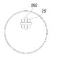
도 4는 본 발명의 또 다른 실시 예에 따른 이동로봇에 구비되는 감지센서의 위치를 나타낸 개요도이다. 도시된 바와 같이, 본 발명에 따른 이동로봇(200)의 신호 수신부(260)는 각각이 식별정보를 가지되, 격벽(262)에 의해 이동로봇(200)의 전면 상단에 서로 다른 방향으로부터 전송되는 안내신호를 감지하도록 감지센서 (261)들이 설치될 수 있다.Figure 4 is a schematic diagram showing the position of the detection sensor provided in the mobile robot according to another embodiment of the present invention. As shown, the
신호 수신부(260)는 이동로봇(200)의 전면 상단에 구비되며, 각각이 식별정보를 가지며 발광부와 수광부를 가진 다수의 감지센서(261)가 격벽(262)에 의해 서로 다른 방향으로부터 전송되는 안내신호를 감지하도록 분할되어 있다.The
도 4는 4개의 감지센서(261)를 포함하며, 각각의 감지센서(261)가 격벽(262)을 통해 분할된 신호 수신부를 도시한 개요도이다. 신호 수신부(260)는 4개의 영역에서 전송되는 신호를 수신하여 신호 추출부(272)로 출력하며, 신호 추출부(272)는 수신된 장애물 감지신호 또는 충전대 안내신호를 수신하여 각각의 주파수 대역에 따라 분류하고, 다수의 감지센서(261)들 중 안내신호가 수신되는 감지센서(261)를 식별정보를 통해 추출하여 충전대(100)의 위치를 산출하고, 산출된 충전대(100)의 위치 정보를 충전대 복귀 처리부(274)로 출력한다.4 is a schematic diagram illustrating a signal receiver including four
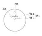
도 5는 본 발명의 또 다른 실시 예에 따른 이동로봇에 구비되는 감지센서의 위치를 나타낸 개요도이다. 도시된 바와 같이, 본 발명에 따른 이동로봇(200)의 신호 수신부(260)는 충전대(100)로부터 출력되는 공간별 서로 다른 주파수 대역을 가지는 안내신호를 수신하여 수신된 안내신호의 주파수 대역을 감지하여 출력하는 공간 감지센서(263)와, 충전대(100)로부터 출력되는 안내신호의 수신 방향을 감지하여 출력하는 방향 감지센서(264)를 포함하여 구성된다.Figure 5 is a schematic diagram showing the position of the detection sensor provided in the mobile robot according to another embodiment of the present invention. As shown, the
공간 감지센서(263)는 충전대(100)로부터 출력되는 안내신호를 수신하는 수광부만으로구성되는 센서로써, 상술한 바와 같이, 다수의 적외선 발광부가 구비되어 있어 서로 다른 주파수를 가진 신호를 각각의 영역으로 발산하는 충전대(100)의 안내신호를 수신하여 수신된 안내신호의 주파수 대역을 감지하여 해당 이동로봇(200)이 현재 충전대(100)를 중심으로 어느 공간상에 위치해 있는지 산출하여 충전대 위치 산출부(273)로 출력한다.The
방향 감지센서(264)는 충전대(100)로부터 출력되는 안내신호가 수신되는 방향을 감지하는 센서로써, 예를 들면 이동로봇(200)의 정면으로부터 전송되는 안내신호를 감지하는 전방 감지센서(264-1)와, 이동로봇(200)의 후면으로부터 전송되는 안내신호를 감지하는 후방 감지센서(264-2)로 구성될 수 있다.The
전방 감지센서(264-1)는 이동로봇(200)의 주행 방향 상의 전방으로부터 안내신호가 수신되었을 경우 감지신호를 충전대 위치 산출부(273)로 출력하며, 후방 감지센서(264-2)는 이동로봇(200)의 주행 방향 상의 후방으로부터 안내신호가 수신되었을 경우 감지신호를 충전대 산출부로 출력한다.The front sensor 264-1 outputs a detection signal to the charging
충전대 위치 산출부(273)는 공간 감지센서(263)를 통해 출력되는 안내신호 주파수 대역을 이용하여 충전대(100)를 중심으로 이동로봇(200)이 위치를 산출하고, 방향 감지센서(264)로부터 출력되는 감지신호를 이용하여 충전대(100)의 복귀 진행 방향을 산출한다.The charging station
상술한 바와 같이, 본 발명에 따른 이동로봇은 장애물을 감지신호와 충전대로부터 출력되는 안내신호를 동시에 수신할 수 있는 감지센서를 이동로봇에 다수 개 형성하고, 수신되는 신호의 주파수를 이용하여 분류 처리함으로써, 이동로봇의 장애물 회피 주행 및 충전대 복귀를 효과적으로 처리할 수 있다.As described above, the mobile robot according to the present invention forms a plurality of detection sensors on the mobile robot which can simultaneously receive obstacle detection signals and guide signals output from the charging station, and classify the signals using the frequencies of the received signals. By doing so, it is possible to effectively handle obstacle avoidance driving and return to the charging stand of the mobile robot.
또한, 이동로봇은 장애물 감지 신호와 충전대 안내신호를 수신하는 감지센서를 공용화함으로써, 측면에 소정 간격으로 이격되게 설치되는 장애물 감지센서를 가지는 이동로봇의 구조적인 변경 없이 충전대 복귀를 처리하는 프로그램의 탑재만으로 효과적인 충전대 복귀를 가능하게 하는 장점을 갖는다.In addition, the mobile robot is equipped with a program for processing the return to the charging station without structural change of the mobile robot having an obstacle detection sensor that is installed at a predetermined interval on the side by sharing the detection sensor receiving the obstacle detection signal and the charging guide guide signal. Only has the advantage of enabling effective charging station return.
이상에서 본 발명은 바람직한 실시 예들을 참조하여 설명되었지만 여기에 한정되는 것은 아니며, 본 발명의 범주를 벗어남이 없이 당업자라면 자명하게 도출 가능한 많은 변형 예들을 포괄하도록 의도된 첨부된 특허청구범위에 의하여 해석되어져야 한다.The present invention has been described above with reference to preferred embodiments, but is not limited thereto, and is interpreted by the appended claims, which are intended to cover many modifications that will be apparent to those skilled in the art without departing from the scope of the present invention. Should be done.
Claims (7)
Translated fromKoreanPriority Applications (3)
| Application Number | Priority Date | Filing Date | Title |
|---|---|---|---|
| KR1020050102517AKR100692897B1 (en) | 2005-10-28 | 2005-10-28 | Mobile robot |
| US11/553,533US7397213B2 (en) | 2005-10-28 | 2006-10-27 | Mobile robot and mobile robot charge station return system |
| CN2006101428977ACN1954974B (en) | 2005-10-28 | 2006-10-27 | Moving robot and moving robot battery recharge room return system |
Applications Claiming Priority (1)
| Application Number | Priority Date | Filing Date | Title |
|---|---|---|---|
| KR1020050102517AKR100692897B1 (en) | 2005-10-28 | 2005-10-28 | Mobile robot |
Publications (1)
| Publication Number | Publication Date |
|---|---|
| KR100692897B1true KR100692897B1 (en) | 2007-03-12 |
Family
ID=37995393
Family Applications (1)
| Application Number | Title | Priority Date | Filing Date |
|---|---|---|---|
| KR1020050102517AExpired - Fee RelatedKR100692897B1 (en) | 2005-10-28 | 2005-10-28 | Mobile robot |
Country Status (3)
| Country | Link |
|---|---|
| US (1) | US7397213B2 (en) |
| KR (1) | KR100692897B1 (en) |
| CN (1) | CN1954974B (en) |
Cited By (4)
| Publication number | Priority date | Publication date | Assignee | Title |
|---|---|---|---|---|
| KR100850227B1 (en) | 2007-03-29 | 2008-08-04 | 엘지전자 주식회사 | Mobile robot return system and its operation method |
| KR101119788B1 (en)* | 2009-05-18 | 2012-03-12 | 주식회사 포스코아이씨티 | Apparatus for driving mobile robot and method for driving thereof |
| WO2021177724A1 (en)* | 2020-03-04 | 2021-09-10 | 엘지전자 주식회사 | Mobile robot and control method therefor |
| KR20240029717A (en)* | 2022-08-26 | 2024-03-06 | (주)공생 | Hospital transfer management system using transfer aids and robots |
Families Citing this family (49)
| Publication number | Priority date | Publication date | Assignee | Title |
|---|---|---|---|---|
| US6956348B2 (en) | 2004-01-28 | 2005-10-18 | Irobot Corporation | Debris sensor for cleaning apparatus |
| KR100692897B1 (en)* | 2005-10-28 | 2007-03-12 | 엘지전자 주식회사 | Mobile robot |
| KR100769910B1 (en)* | 2006-09-11 | 2007-10-24 | 엘지전자 주식회사 | Mobile robot and its operation method |
| KR100818740B1 (en)* | 2006-10-13 | 2008-04-01 | 엘지전자 주식회사 | Robot cleaner and control method accordingly |
| US8010229B2 (en)* | 2006-12-05 | 2011-08-30 | Electronics And Telecommunications Research Institute | Method and apparatus for returning cleaning robot to charge station |
| TWI330305B (en)* | 2006-12-28 | 2010-09-11 | Ind Tech Res Inst | Method for routing a robotic apparatus to a service station and robotic apparatus service system using thereof |
| US8489234B2 (en)* | 2007-07-18 | 2013-07-16 | Lg Electronics Inc. | Mobile robot and controlling method thereof |
| CN101670580B (en)* | 2008-09-11 | 2011-11-30 | 泰怡凯电器(苏州)有限公司 | Intelligent robot system and barrier-free guidance method and electronic guidance mirrors thereof |
| TWI680928B (en) | 2009-04-10 | 2020-01-01 | 美商辛波提克有限責任公司 | Vertical lift system and method for transferring uncontained case unit to and from a multilevel storage structure |
| US8825256B2 (en)* | 2009-06-30 | 2014-09-02 | Lg Electronics Inc. | Charging device of robot cleaner |
| EP2547191B1 (en)* | 2010-03-17 | 2018-09-19 | Husqvarna AB | Method and system for guiding a robotic garden tool to a predetermined position |
| US8442682B2 (en) | 2010-05-28 | 2013-05-14 | Toyota Motor Engineering & Manufacturing North America, Inc. | Autonomous robot charging stations and methods |
| US20120191517A1 (en) | 2010-12-15 | 2012-07-26 | Daffin Jr Mack Paul | Prepaid virtual card |
| US9008884B2 (en) | 2010-12-15 | 2015-04-14 | Symbotic Llc | Bot position sensing |
| US10822168B2 (en) | 2010-12-15 | 2020-11-03 | Symbotic Llc | Warehousing scalable storage structure |
| US9475649B2 (en) | 2010-12-15 | 2016-10-25 | Symbolic, LLC | Pickface builder for storage and retrieval systems |
| US8998554B2 (en) | 2010-12-15 | 2015-04-07 | Symbotic Llc | Multilevel vertical conveyor platform guides |
| EP2659260B1 (en) | 2010-12-30 | 2019-11-20 | iRobot Corporation | Debris monitoring |
| TWI424912B (en)* | 2011-01-28 | 2014-02-01 | Pegatron Corp | Robot control system and method |
| US8532860B2 (en)* | 2011-02-25 | 2013-09-10 | Intellibot Robotics Llc | Methods and systems for automatically yielding to high-priority traffic |
| WO2013005326A1 (en)* | 2011-07-07 | 2013-01-10 | トヨタ自動車株式会社 | Charging cable housing device |
| TWI622540B (en) | 2011-09-09 | 2018-05-01 | 辛波提克有限責任公司 | Automated storage and handling system |
| KR101366860B1 (en)* | 2011-09-20 | 2014-02-21 | 엘지전자 주식회사 | Mobile robot and controlling method of the same |
| CN103294056A (en)* | 2012-03-02 | 2013-09-11 | 苏州宝时得电动工具有限公司 | Automatic walking device and control method thereof |
| US9440350B2 (en) | 2012-03-02 | 2016-09-13 | Positec Power Tools (Suzhou) Co., Ltd | Automatically travelling device and control method therefor |
| CN103576678B (en)* | 2012-07-20 | 2016-12-21 | 苏州宝时得电动工具有限公司 | Auto-returned system and the method controlling automatic running device return bus stop |
| EP2757536B1 (en)* | 2013-01-17 | 2021-03-03 | Wincor Nixdorf International GmbH | Device for the autonomous transport of cash boxes between the till area and the back office |
| US11565598B2 (en)* | 2013-03-15 | 2023-01-31 | Symbotic Llc | Rover charging system with one or more charging stations configured to control an output of the charging station independent of a charging station status |
| JP6525953B2 (en) | 2013-03-15 | 2019-06-05 | シムボティック エルエルシー | Automatic storage and retrieval system |
| TWI594933B (en) | 2013-03-15 | 2017-08-11 | 辛波提克有限責任公司 | Automated storage and retrieval system |
| CN105705441B (en) | 2013-09-13 | 2018-04-10 | 西姆伯蒂克有限责任公司 | Autonomous transport car, the method for storing and fetching system and selection face being transmitted in the system |
| WO2015149132A1 (en)* | 2014-04-04 | 2015-10-08 | Commonwealth Scientific And Industrial Research Organisation | Position tracking method and apparatus |
| US10488865B2 (en)* | 2014-12-16 | 2019-11-26 | Al Incorporated | Methods and systems for robotic surface coverage |
| US9701020B1 (en)* | 2014-12-16 | 2017-07-11 | Bobsweep Inc. | Method and system for robotic surface coverage |
| KR102404258B1 (en)* | 2015-02-06 | 2022-06-02 | 삼성전자주식회사 | Apparatus for returning of robot and returning method thereof |
| CN105527869B (en)* | 2015-12-01 | 2019-03-01 | 纳恩博(北京)科技有限公司 | Smart machine and its intelligent control method |
| EP3398020B1 (en)* | 2015-12-30 | 2019-10-02 | Telecom Italia S.p.A. | Docking system and method for charging a mobile robot |
| US9904283B2 (en) | 2016-03-08 | 2018-02-27 | Fuji Xerox Co., Ltd. | Systems and methods employing coded light to dock aerial drones, self-driving cars and surface robots |
| KR101984101B1 (en)* | 2017-03-06 | 2019-05-30 | 엘지전자 주식회사 | Cleaner and controlling method thereof |
| CN109383799A (en)* | 2017-08-07 | 2019-02-26 | 菜鸟智能物流控股有限公司 | Aircraft charging method and related device |
| CN107765690A (en)* | 2017-09-30 | 2018-03-06 | 湖南应用技术学院 | A kind of robot ambulation system |
| CN107802472A (en)* | 2017-11-22 | 2018-03-16 | 佛山市海科云筹信息技术有限公司 | A kind of blind man's stick and its method with crossing alarm function |
| CN108983246B (en)* | 2018-08-03 | 2023-07-11 | 珠海一微半导体股份有限公司 | Infrared modulation obstacle detection device, detection method and robot |
| CN109407670B (en)* | 2018-12-07 | 2022-03-04 | 美智纵横科技有限责任公司 | Distance detection method and device of sweeping robot and sweeping robot |
| WO2020242959A1 (en) | 2019-05-24 | 2020-12-03 | Sharkninja Operating Llc | Obstacle sensor system and autonomous device using the same |
| CN111823232A (en)* | 2020-06-23 | 2020-10-27 | 张梅 | Safety detection method for inspection robot |
| CN112220412B (en)* | 2020-09-27 | 2022-04-08 | 小狗电器互联网科技(北京)股份有限公司 | Robot automatic return method and device and electronic equipment |
| CN112731924A (en) | 2020-12-17 | 2021-04-30 | 深圳市银星智能科技股份有限公司 | Recharging method for mobile robot, mobile robot and storage medium |
| KR20250027366A (en)* | 2023-08-17 | 2025-02-26 | 삼성전자주식회사 | Robot cleaner and controlling method thereof |
Family Cites Families (18)
| Publication number | Priority date | Publication date | Assignee | Title |
|---|---|---|---|---|
| US4679152A (en)* | 1985-02-20 | 1987-07-07 | Heath Company | Navigation system and method for a mobile robot |
| US5179329A (en)* | 1989-04-25 | 1993-01-12 | Shinko Electric Co., Ltd. | Travel control method, travel control device, and mobile robot for mobile robot systems |
| JP2679346B2 (en)* | 1990-03-28 | 1997-11-19 | 神鋼電機株式会社 | Charging control method for mobile robot system |
| US5995884A (en)* | 1997-03-07 | 1999-11-30 | Allen; Timothy P. | Computer peripheral floor cleaning system and navigation method |
| DE69821659T2 (en)* | 1997-11-27 | 2004-12-16 | Solar And Robotics S.A. | cleaning robot |
| US6532404B2 (en)* | 1997-11-27 | 2003-03-11 | Colens Andre | Mobile robots and their control system |
| US6690134B1 (en)* | 2001-01-24 | 2004-02-10 | Irobot Corporation | Method and system for robot localization and confinement |
| US6711280B2 (en)* | 2001-05-25 | 2004-03-23 | Oscar M. Stafsudd | Method and apparatus for intelligent ranging via image subtraction |
| DE10231391A1 (en)* | 2002-07-08 | 2004-02-12 | Alfred Kärcher Gmbh & Co. Kg | Tillage system |
| DE10231388A1 (en)* | 2002-07-08 | 2004-02-05 | Alfred Kärcher Gmbh & Co. Kg | Tillage system |
| US7133746B2 (en)* | 2003-07-11 | 2006-11-07 | F Robotics Acquistions, Ltd. | Autonomous machine for docking with a docking station and method for docking |
| KR100565227B1 (en)* | 2003-12-22 | 2006-03-30 | 엘지전자 주식회사 | Position recognition device and method of mobile robot |
| KR20050063543A (en) | 2003-12-22 | 2005-06-28 | 엘지전자 주식회사 | Position confirmation apparatus and method for mobile robot |
| US7332890B2 (en)* | 2004-01-21 | 2008-02-19 | Irobot Corporation | Autonomous robot auto-docking and energy management systems and methods |
| KR100766434B1 (en)* | 2005-07-22 | 2007-10-15 | 엘지전자 주식회사 | Moving object capable of image recognition and moving method |
| KR100766435B1 (en)* | 2005-10-27 | 2007-10-15 | 엘지전자 주식회사 | Mobile robot charging station return system |
| KR100692897B1 (en)* | 2005-10-28 | 2007-03-12 | 엘지전자 주식회사 | Mobile robot |
| KR100766439B1 (en)* | 2006-03-29 | 2007-10-12 | 엘지전자 주식회사 | Mobile robot charging station return system |
- 2005
- 2005-10-28KRKR1020050102517Apatent/KR100692897B1/ennot_activeExpired - Fee Related
- 2006
- 2006-10-27USUS11/553,533patent/US7397213B2/enactiveActive
- 2006-10-27CNCN2006101428977Apatent/CN1954974B/ennot_activeExpired - Fee Related
Cited By (6)
| Publication number | Priority date | Publication date | Assignee | Title |
|---|---|---|---|---|
| KR100850227B1 (en) | 2007-03-29 | 2008-08-04 | 엘지전자 주식회사 | Mobile robot return system and its operation method |
| KR101119788B1 (en)* | 2009-05-18 | 2012-03-12 | 주식회사 포스코아이씨티 | Apparatus for driving mobile robot and method for driving thereof |
| WO2021177724A1 (en)* | 2020-03-04 | 2021-09-10 | 엘지전자 주식회사 | Mobile robot and control method therefor |
| US12318062B2 (en) | 2020-03-04 | 2025-06-03 | Lg Electronics Inc. | Mobile robot and control method therefor |
| KR20240029717A (en)* | 2022-08-26 | 2024-03-06 | (주)공생 | Hospital transfer management system using transfer aids and robots |
| KR102839649B1 (en) | 2022-08-26 | 2025-08-01 | (주)공생 | Hospital transfer management system using transfer aids and robots |
Also Published As
| Publication number | Publication date |
|---|---|
| US7397213B2 (en) | 2008-07-08 |
| CN1954974B (en) | 2010-05-12 |
| US20070096676A1 (en) | 2007-05-03 |
| CN1954974A (en) | 2007-05-02 |
Similar Documents
| Publication | Publication Date | Title |
|---|---|---|
| KR100692897B1 (en) | Mobile robot | |
| KR100766439B1 (en) | Mobile robot charging station return system | |
| CN110300537B (en) | Dust collector and control method thereof | |
| KR100468107B1 (en) | Robot cleaner system having external charging apparatus and method for docking with the same apparatus | |
| CN110621209B (en) | Cleaner and control method thereof | |
| KR100766435B1 (en) | Mobile robot charging station return system | |
| KR100669892B1 (en) | Mobile robot with obstacle avoidance and method | |
| KR100654676B1 (en) | robotic vacuum | |
| KR20060111780A (en) | Positioning system of mobile robot, charging station return system using same and method | |
| KR20080060535A (en) | Automatic charging device of autonomous mobile robot and automatic charging method using the same | |
| EP3738495B1 (en) | Robotic vacuum cleaner and control method therefor | |
| KR102033676B1 (en) | Charging System for Mobile Robot and Method thereof | |
| KR100820585B1 (en) | Mobile robot system and control method | |
| KR102309898B1 (en) | Docking equipment and Moving robot system | |
| KR100704486B1 (en) | Automatic charging station return system and method for mobile robot | |
| KR100632436B1 (en) | Autonomous mobile robot system with external charging device and control method | |
| KR100485707B1 (en) | Robot cleaner system having external charging apparatus and method for docking with the same apparatus | |
| KR20080078327A (en) | Automatic charging device of mobile robot and automatic charging method using the same | |
| CN216167276U (en) | Self-moving robot | |
| KR100738887B1 (en) | Driving method of mobile robot and mobile robot using it | |
| KR101353309B1 (en) | Robot cleaner system and control method thereof | |
| JP7107658B2 (en) | AUTONOMOUS RUNNING VACUUM CLEANER, AUTONOMOUS RUNNING TYPE VACUUM CLEANER SYSTEM, AND MOVING OBJECT | |
| EP4116044A1 (en) | Mobile robot and control method therefor | |
| KR20100100518A (en) | Apparatus and method for controlling reservation cleaning of robot cleaner | |
| KR100728227B1 (en) | Travel control device of mobile robot and its method |
Legal Events
| Date | Code | Title | Description |
|---|---|---|---|
| A201 | Request for examination | ||
| PA0109 | Patent application | St.27 status event code:A-0-1-A10-A12-nap-PA0109 | |
| PA0201 | Request for examination | St.27 status event code:A-1-2-D10-D11-exm-PA0201 | |
| E902 | Notification of reason for refusal | ||
| PE0902 | Notice of grounds for rejection | St.27 status event code:A-1-2-D10-D21-exm-PE0902 | |
| P11-X000 | Amendment of application requested | St.27 status event code:A-2-2-P10-P11-nap-X000 | |
| P13-X000 | Application amended | St.27 status event code:A-2-2-P10-P13-nap-X000 | |
| P11-X000 | Amendment of application requested | St.27 status event code:A-2-2-P10-P11-nap-X000 | |
| P13-X000 | Application amended | St.27 status event code:A-2-2-P10-P13-nap-X000 | |
| E701 | Decision to grant or registration of patent right | ||
| PE0701 | Decision of registration | St.27 status event code:A-1-2-D10-D22-exm-PE0701 | |
| GRNT | Written decision to grant | ||
| PR0701 | Registration of establishment | St.27 status event code:A-2-4-F10-F11-exm-PR0701 | |
| PR1002 | Payment of registration fee | St.27 status event code:A-2-2-U10-U11-oth-PR1002 Fee payment year number:1 | |
| PG1601 | Publication of registration | St.27 status event code:A-4-4-Q10-Q13-nap-PG1601 | |
| PN2301 | Change of applicant | St.27 status event code:A-5-5-R10-R13-asn-PN2301 St.27 status event code:A-5-5-R10-R11-asn-PN2301 | |
| R18-X000 | Changes to party contact information recorded | St.27 status event code:A-5-5-R10-R18-oth-X000 | |
| R18-X000 | Changes to party contact information recorded | St.27 status event code:A-5-5-R10-R18-oth-X000 | |
| PR1001 | Payment of annual fee | St.27 status event code:A-4-4-U10-U11-oth-PR1001 Fee payment year number:4 | |
| PR1001 | Payment of annual fee | St.27 status event code:A-4-4-U10-U11-oth-PR1001 Fee payment year number:5 | |
| PR1001 | Payment of annual fee | St.27 status event code:A-4-4-U10-U11-oth-PR1001 Fee payment year number:6 | |
| FPAY | Annual fee payment | Payment date:20130226 Year of fee payment:7 | |
| PR1001 | Payment of annual fee | St.27 status event code:A-4-4-U10-U11-oth-PR1001 Fee payment year number:7 | |
| FPAY | Annual fee payment | Payment date:20140224 Year of fee payment:8 | |
| PR1001 | Payment of annual fee | St.27 status event code:A-4-4-U10-U11-oth-PR1001 Fee payment year number:8 | |
| FPAY | Annual fee payment | Payment date:20150224 Year of fee payment:9 | |
| PR1001 | Payment of annual fee | St.27 status event code:A-4-4-U10-U11-oth-PR1001 Fee payment year number:9 | |
| PN2301 | Change of applicant | St.27 status event code:A-5-5-R10-R13-asn-PN2301 St.27 status event code:A-5-5-R10-R11-asn-PN2301 | |
| FPAY | Annual fee payment | Payment date:20160224 Year of fee payment:10 | |
| PR1001 | Payment of annual fee | St.27 status event code:A-4-4-U10-U11-oth-PR1001 Fee payment year number:10 | |
| P22-X000 | Classification modified | St.27 status event code:A-4-4-P10-P22-nap-X000 | |
| FPAY | Annual fee payment | Payment date:20170214 Year of fee payment:11 | |
| PR1001 | Payment of annual fee | St.27 status event code:A-4-4-U10-U11-oth-PR1001 Fee payment year number:11 | |
| PR1001 | Payment of annual fee | St.27 status event code:A-4-4-U10-U11-oth-PR1001 Fee payment year number:12 | |
| LAPS | Lapse due to unpaid annual fee | ||
| PC1903 | Unpaid annual fee | St.27 status event code:A-4-4-U10-U13-oth-PC1903 Not in force date:20190306 Payment event data comment text:Termination Category : DEFAULT_OF_REGISTRATION_FEE | |
| PC1903 | Unpaid annual fee | St.27 status event code:N-4-6-H10-H13-oth-PC1903 Ip right cessation event data comment text:Termination Category : DEFAULT_OF_REGISTRATION_FEE Not in force date:20190306 | |
| PN2301 | Change of applicant | St.27 status event code:A-5-5-R10-R13-asn-PN2301 St.27 status event code:A-5-5-R10-R11-asn-PN2301 | |
| P22-X000 | Classification modified | St.27 status event code:A-4-4-P10-P22-nap-X000 | |
| P22-X000 | Classification modified | St.27 status event code:A-4-4-P10-P22-nap-X000 | |
| P22-X000 | Classification modified | St.27 status event code:A-4-4-P10-P22-nap-X000 |