KR100692389B1 - Differential pressure switch - Google Patents
Differential pressure switchDownload PDFInfo
- Publication number
- KR100692389B1 KR100692389B1KR1020050032998AKR20050032998AKR100692389B1KR 100692389 B1KR100692389 B1KR 100692389B1KR 1020050032998 AKR1020050032998 AKR 1020050032998AKR 20050032998 AKR20050032998 AKR 20050032998AKR 100692389 B1KR100692389 B1KR 100692389B1
- Authority
- KR
- South Korea
- Prior art keywords
- piston
- housing
- differential pressure
- pressure
- accommodation chamber
- Prior art date
- Legal status (The legal status is an assumption and is not a legal conclusion. Google has not performed a legal analysis and makes no representation as to the accuracy of the status listed.)
- Expired - Fee Related
Links
Images


Classifications
- B—PERFORMING OPERATIONS; TRANSPORTING
- B66—HOISTING; LIFTING; HAULING
- B66C—CRANES; LOAD-ENGAGING ELEMENTS OR DEVICES FOR CRANES, CAPSTANS, WINCHES, OR TACKLES
- B66C1/00—Load-engaging elements or devices attached to lifting or lowering gear of cranes or adapted for connection therewith for transmitting lifting forces to articles or groups of articles
- B66C1/02—Load-engaging elements or devices attached to lifting or lowering gear of cranes or adapted for connection therewith for transmitting lifting forces to articles or groups of articles by suction means
- B66C1/0218—Safety measures, e.g. sensors, duplicate functions
- B—PERFORMING OPERATIONS; TRANSPORTING
- B66—HOISTING; LIFTING; HAULING
- B66C—CRANES; LOAD-ENGAGING ELEMENTS OR DEVICES FOR CRANES, CAPSTANS, WINCHES, OR TACKLES
- B66C15/00—Safety gear
- B66C15/02—Safety gear for retaining load-engaging elements in the event of rope or cable breakage
- G—PHYSICS
- G01—MEASURING; TESTING
- G01F—MEASURING VOLUME, VOLUME FLOW, MASS FLOW OR LIQUID LEVEL; METERING BY VOLUME
- G01F1/00—Measuring the volume flow or mass flow of fluid or fluent solid material wherein the fluid passes through a meter in a continuous flow
- G01F1/05—Measuring the volume flow or mass flow of fluid or fluent solid material wherein the fluid passes through a meter in a continuous flow by using mechanical effects
- G01F1/34—Measuring the volume flow or mass flow of fluid or fluent solid material wherein the fluid passes through a meter in a continuous flow by using mechanical effects by measuring pressure or differential pressure
- H—ELECTRICITY
- H01—ELECTRIC ELEMENTS
- H01H—ELECTRIC SWITCHES; RELAYS; SELECTORS; EMERGENCY PROTECTIVE DEVICES
- H01H35/00—Switches operated by change of a physical condition
- H01H35/24—Switches operated by change of fluid pressure, by fluid pressure waves, or by change of fluid flow
- H01H35/26—Details
- B—PERFORMING OPERATIONS; TRANSPORTING
- B60—VEHICLES IN GENERAL
- B60G—VEHICLE SUSPENSION ARRANGEMENTS
- B60G2300/00—Indexing codes relating to the type of vehicle
- B60G2300/06—Cranes
Landscapes
- Engineering & Computer Science (AREA)
- Mechanical Engineering (AREA)
- Physics & Mathematics (AREA)
- Fluid Mechanics (AREA)
- General Physics & Mathematics (AREA)
- Switches Operated By Changes In Physical Conditions (AREA)
Abstract
Translated fromKoreanDescription
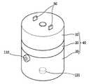
Translated fromKorean도1은 본 발명의 일실시예에 따른 차압스위치의 구성을 나타낸 사시도,1 is a perspective view showing the configuration of a differential pressure switch according to an embodiment of the present invention;
도2는 본 발명의 일실시예에 따른 차압스위치의 구성을 나타낸 단면도,2 is a cross-sectional view showing the configuration of a differential pressure switch according to an embodiment of the present invention;
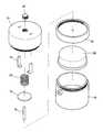
도3은 본 발명의 일실시예에 따른 차압스위치의 구성을 분리하여 나타낸 사시도,Figure 3 is a perspective view showing a separated configuration of the differential pressure switch according to an embodiment of the present invention,
도4는 종래 기술의 압력스위치의 구성을 나타낸 단면도,Figure 4 is a cross-sectional view showing the configuration of a pressure switch of the prior art,
도5는 데릭실린더와 차압스위치의 유압회로도이다.5 is a hydraulic circuit diagram of a derrick cylinder and a differential pressure switch.
<도면부호의 간단한 설명><Brief Description of Drawings>
10 : 상부 케이스20 : 격막10: upper case 20: diaphragm
30 : 하부 케이스40 : 하우징30: lower case 40: housing
50 : 터미널60 : 접촉디스크50: terminal 60: contact disk
70 : 지지대80 : 스위치부70: support 80: switch
90 : 압력조절너트100 : 탄성스프링90: pressure adjusting nut 100: elastic spring
110 : 상부포트120 : 하부포트110: upper port 120: lower port
130 : 피스톤140 : 제1수용실130: piston 140: first receiving chamber
150 : 제2수용실150: second room
본 발명은 차압스위치에 관한 것으로, 보다 상세하게는 압력이 다른 두 유체를 흡입하여 차압을 측정하고 압력을 받는 피스톤의 면적비를 조절하여 차압에 따라 작동되는 차압스위치에 관한 것이다.The present invention relates to a differential pressure switch, and more particularly, to a differential pressure switch operated by a differential pressure by measuring a differential pressure by suctioning two fluids having different pressures and adjusting an area ratio of a piston under pressure.
하물을 들어올려서 운반하는 기계장치인 크레인에는 과부하를 방지하기 위하여 과부하 방지 장치가 설치되어 있다. 이러한 과부하 방지 장치들에는 하물의 하중이 과하중인지 여부를 판단하기 위하여 압력스위치가 사용되고 있다. 크레인의 부움(Boom)에 하물을 매달아 들어올릴 경우, 데릭실린더를 신장시키어 부움을 상승시킨다. 즉, 데릭실린더 내부의 피스톤 하부에 압유를 공급시키고, 압유가 피스톤을 전진시키어 데릭실린더를 신장시킨다. 데릭실린더가 신장되면 데릭실린더에 의하여 지지되는 부움이 상승하여 하물을 들어올린다. 이 때 데릭실린더의 피스톤 하부에는 하물의 하중에 의한 압력이 작용하므로, 압력스위치를 사용하여 데릭실린더의 피스톤 하부에서 상기의 압력을 측정한다. 압력스위치에 의하여 측정되는 압력이 설정치 이상을 초과하면 압력스위치가 온(ON) 된다. 압력스위치가 온(ON) 될 경우 크레인에 과하중이 작용하는 것으로 판단하여 크레인의 운전이 정지 된다.Cranes, which are mechanisms for lifting and transporting loads, are equipped with overload protection devices to prevent overloading. In such overload protection devices, a pressure switch is used to determine whether a load of a load is overloaded. When lifting a load onto the crane's boom, the derrick cylinder is extended to raise the boom. That is, pressure oil is supplied to the lower part of the piston inside the derrick cylinder, and the pressure oil advances the piston to extend the derrick cylinder. When the derrick cylinder is extended, the boolean supported by the derrick cylinder is raised to lift the load. At this time, since the pressure by the load of the load acts on the lower part of the piston of the derrick cylinder, the above pressure is measured at the lower part of the piston of the derrick cylinder using a pressure switch. If the pressure measured by the pressure switch exceeds the set value, the pressure switch is turned ON. When the pressure switch is turned on (ON), the crane is stopped because it is determined that an overload is applied to the crane.
도4에는 종래의 과부하 방지 장치에 사용되는 압력스위치가 도시되어 있다. 압유가 흡입포트(280)를 통과하여 유입되면 피스톤(270)에 압력을 가한다. 피스톤(270)에 가해지는 압력이 탄성스프링(240)의 탄성력을 능가하면 피스톤(270)이 전진한다. 피스톤(270)이 전진하면 피스톤(270)과 지지대(260)에 의하여 연결되어 있 는 접촉디스크(250)가 전진한다. 접촉디스크(250)가 전진함에 따라 접촉디스크(250)가 터미널(220)과 연결되어 압력스위치가 온(ON) 된다. 또한, 압력이 감소하여 탄성스프링(250)의 탄성력 보다 작아질 경우 탄성스프링(250)에 의하여 접촉디스크(250)가 후퇴하여 압력스위치는 오프(OFF) 된다. 탄성스프링(250)의 탄성력은 압력조절너트(230)를 사용하여 조절이 가능하다.Figure 4 shows the pressure switch used in the conventional overload protection device. When the hydraulic oil flows in through the
종래의 기술에 의하면, 과부하 방지 장치에 사용되는 압력스위치는 작동유체를 한 곳에서만 흡입하여 압력을 측정할 수 있었다. 따라서 데릭실린더의 피스톤 하부에서만 유압을 측정하여 크레인에 작용하는 하중이 과하중인지 여부를 판단하였다. 데릭실린더 피스톤의 하부에는 하물의 중량에 의한 압력 뿐 만 아니라 데릭실린더 내의 피스톤 상부의 작동유체의 유압까지 같이 작용한다. 그래서 종래의 압력스위치에 의하여 검출되는 압력은 하물의 중량에 의한 압력 뿐 만 아니라 데릭실린더 내의 피스톤 상부의 유압까지 같이 포함되므로 실제의 하중에 의한 압력보다 높은 값을 나타낸다. 따라서 종래의 압력스위치로는 실제의 하중에 의한 과하중을 정확하게 방지할 수 없다는 문제점이 있다.According to the prior art, the pressure switch used in the overload protection device was able to measure the pressure by suctioning the working fluid in only one place. Therefore, the hydraulic pressure was measured only at the lower part of the piston of the derrick cylinder to determine whether the load acting on the crane was underload. The lower part of the derrick cylinder piston acts not only on the pressure by the weight of the load but also on the hydraulic pressure of the working fluid on the upper part of the piston in the derrick cylinder. Therefore, the pressure detected by the conventional pressure switch includes not only the pressure by the weight of the load but also the hydraulic pressure of the piston upper part in the derrick cylinder, and thus represents a higher value than the pressure by the actual load. Therefore, there is a problem that the conventional pressure switch can not accurately prevent the overload by the actual load.
또한, 두 곳에서 압력을 측정하여 실제의 하중이 과하중인지 여부를 판단하기 위해서는 종래의 압력스위치를 2개 사용하여야 한다. 따라서 2개의 압력스위치를 사용하는 경우에는 2개의 압력스위치에서 나오는 전기신호를 상호 비교하여 차압에 해당하는 전기신호를 출력해야 하므로 별도의 전자시스템이 필요하게 되어 차압을 측정하는데 비용이 증가한다는 문제점이 있다.In addition, two conventional pressure switches should be used to determine whether the actual load is under load by measuring the pressure at two places. Therefore, when two pressure switches are used, the electrical signals from the two pressure switches must be compared with each other to output an electrical signal corresponding to the differential pressure. Therefore, a separate electronic system is required, which increases the cost of measuring the differential pressure. have.
또한, 데릭실린더 내의 피스톤은 상면에 피스톤 로드가 연결되어 있으므로 압력을 받는 면적이 상면과 하면에서 면적차이가 발생한다. 따라서 단순한 차압스위치 만으로는 데릭실린더 상부의 허압을 제거할 수 없다는 문제점이 있다.In addition, since the piston rod is connected to the upper surface of the piston in the derrick cylinder, an area under pressure occurs between the upper surface and the lower surface. Therefore, there is a problem in that the pressure of the upper part of the derrick cylinder cannot be removed by a simple differential pressure switch alone.
본 발명은 상기와 같은 종래의 문제점을 해소하기 위해 안출된 것으로 본 발명의 차압스위치는 압력이 다른 작동유체를 흡입하여 차압에 따라 작동하는 스위치를 제공하는 데 있다. 즉, 데릭실린더 내의 피스톤 하부와 상부의 작동유체를 흡입하여 그 차압에 의하여 작동되는 스위치를 제공하기 위함이다.The present invention has been made to solve the conventional problems as described above, the differential pressure switch of the present invention is to provide a switch that operates in accordance with the differential pressure by suction the working fluid of different pressure. That is, it is to provide a switch operated by the differential pressure by sucking the working fluid of the lower and upper piston in the derrick cylinder.
본 발명의 다른 목적은 두 곳에서 압유를 유입하여 기계식으로 차압을 측정함으로써 차압을 측정하는데 비용을 감소할 수 있는 차압스위치를 제공하기 위함이다.Another object of the present invention is to provide a differential pressure switch that can reduce the cost of measuring the differential pressure by measuring the differential pressure mechanically by introducing the pressure oil in two places.
본 발명의 또 다른 목적은 차압스위치 내부에서 압력을 받는 피스톤의 상단과 하단의 단면적을 조절하여 실질적인 하중에 의하여 동작할 수 있는 차압스위치를 제공하기 위함이다.Still another object of the present invention is to provide a differential pressure switch capable of operating by a substantial load by adjusting the cross-sectional area of the upper and lower ends of the piston under pressure in the differential pressure switch.
이와 같은 본 발명의 목적을 달성하기 위한 본 발명의 특징은, 상단면적과 하단면적이 다른 피스톤과; 상기 피스톤의 왕복운동에 의하여 작동되는 스위치부와; 상기 피스톤이 내부에서 왕복운동 하는 제1수용실과 상기 스위치부를 수용하는 제2수용실을 가지는 하우징과; 제1작동유체가 상기 제1수용실로 유입되어 상기 피스톤의 상단에 압력을 가하도록 상기 하우징에 설치된 상부포트와; 제2작동유체가 상기 제1수용실로 유입되어 상기 피스톤의 하단에 압력을 가하도록 상기 하우징에 설치된 하부포트와; 상기 피스톤을 복귀시키는 탄성스프링과; 상기 하우징의 외벽에 설치되어 상기 탄성스프링의 탄성력을 조절하는 압력조절너트를 구비하여; 상기 피스톤 양단의 압력차에 의한 힘이 상기 탄성스프링의 탄성력을 능가하면 상기 피스톤을 운동시키어 스위치부가 온 되도록 설정된 것을 특징으로 한다.Features of the present invention for achieving the object of the present invention, the upper and lower area piston and the other; A switch unit operated by the reciprocating motion of the piston; A housing having a first accommodation chamber in which the piston reciprocates and a second accommodation chamber accommodating the switch unit; An upper port installed in the housing so that a first working fluid flows into the first accommodation chamber and pressurizes an upper end of the piston; A lower port installed in the housing so that a second working fluid flows into the first accommodation chamber to apply pressure to a lower end of the piston; An elastic spring for returning the piston; A pressure adjusting nut installed on an outer wall of the housing to adjust an elastic force of the elastic spring; When the force by the pressure difference between the two ends of the piston exceeds the elastic force of the elastic spring is characterized in that the piston is set to move the switch is turned on.
또한, 상기 스위치부는 그 일단이 제1수용실로 삽입되어 피스톤의 일단에 연결되는 지지대와, 제2수용실 내에서 상기 지지대의 타단에 지지되어 있는 접촉디스크와, 상기 하우징의 외벽을 통하여 제2수용실로 인입되어 상기 접촉디스크와 연결시 전기회로를 통전시키는 터미널을 구비하는 것이 바람직하다.In addition, the switch unit has one end inserted into the first accommodation chamber and connected to one end of the piston, a contact disk supported at the other end of the support in the second accommodation chamber, and a second accommodation through the outer wall of the housing. It is preferable to have a terminal drawn into the thread and energizing an electric circuit when connected to the contact disk.
이하에서는, 본 발명에 따른 차압스위치의 바람직한 실시예를 첨부된 도면들에 의거하여 상세하게 설명한다.Hereinafter, a preferred embodiment of the differential pressure switch according to the present invention will be described in detail with reference to the accompanying drawings.
도1 내지 도3을 참조하면 본 발명에 따른 차압스위치는 제1수용실(140)과 제2수용실(150)을 가지는 하우징(40)과, 제1수용실 내부에서 왕복운동 하는 피스톤(130)과, 제2수용실 내부에서 피스톤(130)의 왕복운동에 따라 온(ON) 또는 오프(OFF) 되는 스위치부(80)와, 피스톤(130)을 복귀시키는 탄성스프링(100)과, 탄성스프링(100)의 탄성력을 조절하는 압력조절너트(90)를 구비한다.1 to 3, the differential pressure switch according to the present invention includes a
하우징(40)은 그 내부에 스위치부(80)를 수용할 수 있는 제2수용실(150)과 피스톤(130)이 왕복운동 할 수 있는 제1수용실(140)을 구비한다. 상부 케이스(10)와 격막(20)의 일측이 결합하여 제2수용실(150)을 형성하며, 하부 케이스(30)와 격막(20)의 타측이 결합하여 제1수용실(140)을 형성한다. 하부 케이스(30)에는 압유를 흡입하여 피스톤(130)의 상면에 압력을 가할 수 있도록 상면포트(110)와 또 다 른 압유를 흡입하여 피스톤(130)의 하면에 압력을 가할 수 있도록 하면포트(120)가 설치되어 있다. 격막(20)은 제1수용실(140)과 제2수용실(150)을 분리시키며, 격막(20)의 중앙에는 접촉디스크(60)를 피스톤(130)의 상면에 지지할 수 있는 지지대(70)를 삽입할 구멍이 형성되어 있다. 지지대(70)가 삽입될 경우 제1수용실(140)과 제2수용실(150)은 실링 되어 있다.The
스위치부(80)는 제2수용실(150) 내에서 접촉디스크(60)와 터미널(50) 및 접촉디스크(60)를 제1수용실(140) 내에 있는 피스톤(130)에 지지시키는 지지대(70)를 구비하고 있다. 터미널(50)은 일측이 전기회로와 연결될 수 있도록 상부 케이스(10)의 외부에 돌출되어 있고, 타측이 상부 케이스(10) 내부의 제2수용실(150)에 삽입되어 있다. 접촉디스크(60)는 제2수용실(150) 내에서 지지대(70)의 일측에 지지되어 있다. 지지대(70)의 타측은 제1수용실(140)에 삽입되어 피스톤(130)의 상면과 연결되어 있어서 피스톤(130)과 접촉디스크(60)가 함께 운동하게 한다. 따라서 피스톤(130)이 왕복운동 함에 따라 접촉디스크(60)와 터미널(50)은 연결 또는 분리된다. 터미널(50)과 접촉디스크(60)가 연결될 경우 차압스위치는 온 된다.The
피스톤(130)은 유압을 받는 상단의 면적과 하단의 면적을 달리한다. 상부포트(110)를 통하여 유입된 압유는 피스톤(130)의 상면에 압력을 가하고, 하부포트(120)를 통하여 유입된 압유는 피스톤(130)의 하면에 압력을 가한다. 따라서 도5와 같이 데릭실린더(300) 내부 피스톤(320)의 상면에 작용하는 압유가 차압스위치의 상부포트(110)에 유입되도록 하고, 데릭실린더(300) 내부 피스톤(320)의 하면에 작용하는 압유가 차압스위치의 하부포트(120)에 유입되도록 유압회로를 구성하면 데 릭실린더(300)에 작용하는 차압을 측정할 수 있다. 다만, 데릭실린더(300) 하부의 유압은 데릭실린더(300) 내부 피스톤(320)의 하단 면적에 작용하고 데릭실린더(300) 상부의 유압은 데릭실린더(300) 내부 피스톤(320)의 상단 면적에 작용하나 데릭실린더(300) 내부 피스톤(320)의 상단에는 피스톤로드가 연결되어 있어서 유압을 받는 피스톤(320)의 상단과 하단의 면적이 동일하지 않다. 따라서 데릭실린더(300) 상부의 유압의 효과를 정확하게 제거하기 위하여 차압스위치 내부에서 압력을 받는 피스톤(130)의 상단과 하단의 면적비를 데릭실린더(300) 내부의 피스톤(320)에서 유압을 받는 상단과 하단의 면적비와 같이 한다.The
탄성스프링(100)은 피스톤(130) 상단과 하단의 압력차에 의한 힘이 일정한 값에 도달할 때까지 접촉디스크(60)와 터미널(50)이 분리되도록 피스톤(130)에 탄성력을 제공한다. 따라서 데릭실린더(300)에 과하중이 부하되어 차압스위치 내의 피스톤(130)의 상단과 하단의 압력차에 의한 힘이 탄성스프링(100)의 탄성력을 능가하면 피스톤(130)이 전진하여 터미널(50)과 접촉디스크(60)가 연결되어 차압스위치가 온 된다. 그러나 압력차에 의한 힘이 감소하면 터미널(50)과 접촉디스크(60)가 분리되어 차압스위치가 오프 된다. 탄성스프링의 탄성력은 상부 케이스(10)의 외벽에 설치된 압력조절나사(90)를 사용하여 조절할 수 있다.The
이하에서는 본 발명의 실시예에 따른 차압스위치의 작용을 설명한다.Hereinafter, the operation of the differential pressure switch according to an embodiment of the present invention.
고압의 제1작동유체는 상부포트(110)를 통하여 하우징(80) 내부로 유입되고, 고압의 제2작동유체는 하부포트(120)를 통하여 하우징(80) 내부로 유입된다. 상부포트(110)를 통하여 유입된 압유는 피스톤(130)의 상면에 압력을 가하고, 하부포트 (120)를 통하여 유입된 압유는 피스톤(130)의 하면에 압력을 가한다. 피스톤(130) 상ㆍ하면의 차압에 의한 힘이 탄성스프링(100)의 탄성력을 능가하면 피스톤(130)은 전진한다. 피스톤(130)이 전진할 경우 지지대(70)에 의하여 피스톤(130)과 고정된 접촉디스크(60)가 전진하여 터미널(50)과 연결된다. 따라서 접촉디스크(60)와 터미널(50)과 연결될 경우 차압스위치는 온 된다.The high pressure first working fluid is introduced into the
본 발명에 의하면, 압력이 다른 두 작동유체를 흡입하여 그 차압에 의하여 작동되는 차압스위치를 제공한다. 따라서 본 발명에 의한 차압스위치는 데릭실린더 상부의 허압을 제거하여 실제적인 하중에 의하여 작동할 수 있는 차압스위치를 제공함으로써 보다 정밀한 하중 범위 까지 동작할 수 있는 과부하 방지 시스템에 이용될 수 있다.According to the present invention, there is provided a differential pressure switch which sucks two working fluids having different pressures and is operated by the differential pressure. Therefore, the differential pressure switch according to the present invention can be used in an overload protection system capable of operating up to a more precise load range by providing a differential pressure switch that can operate according to an actual load by removing the pressure on the upper part of the derrick cylinder.
앞서 설명되고, 도면에 도시된 본 발명의 일 실시예는 본 발명의 기술적 사상을 한정하는 것으로 해석되어서는 안 된다. 본 발명의 보호범위는 청구범위에 기재된 사항에 의하여만 제한되고, 본 발명의 기술분야에서 통상의 지식을 가진 자는 본 발명의 기술적 사상을 다양한 형태로 개량 변경하는 것이 가능하다. 따라서 이러한 개량 및 변경은 통상의 지식을 가진 자에게 자명한 것인 한 본 발명의 보호범위에 속하게 될 것이다.An embodiment of the present invention described above and illustrated in the drawings should not be construed as limiting the technical spirit of the present invention. The protection scope of the present invention is limited only by the matters described in the claims, and those skilled in the art can change and change the technical idea of the present invention in various forms. Therefore, such improvements and modifications will fall within the protection scope of the present invention, as will be apparent to those skilled in the art.
Claims (4)
Translated fromKoreanPriority Applications (1)
| Application Number | Priority Date | Filing Date | Title |
|---|---|---|---|
| KR1020050032998AKR100692389B1 (en) | 2005-04-21 | 2005-04-21 | Differential pressure switch |
Applications Claiming Priority (1)
| Application Number | Priority Date | Filing Date | Title |
|---|---|---|---|
| KR1020050032998AKR100692389B1 (en) | 2005-04-21 | 2005-04-21 | Differential pressure switch |
Publications (2)
| Publication Number | Publication Date |
|---|---|
| KR20060110596A KR20060110596A (en) | 2006-10-25 |
| KR100692389B1true KR100692389B1 (en) | 2007-03-09 |
Family
ID=37616365
Family Applications (1)
| Application Number | Title | Priority Date | Filing Date |
|---|---|---|---|
| KR1020050032998AExpired - Fee RelatedKR100692389B1 (en) | 2005-04-21 | 2005-04-21 | Differential pressure switch |
Country Status (1)
| Country | Link |
|---|---|
| KR (1) | KR100692389B1 (en) |
Citations (4)
| Publication number | Priority date | Publication date | Assignee | Title |
|---|---|---|---|---|
| JPH01281626A (en)* | 1988-05-06 | 1989-11-13 | Meidensha Corp | Operation device for switching part |
| JPH04503301A (en)* | 1988-12-01 | 1992-06-18 | ザ トラスティーズ オブ ザ ユニバーシティ オブ ノース カロライナ | Synthetic interleukin-6 |
| JPH11353987A (en)* | 1998-04-16 | 1999-12-24 | Dwyer Instr Inc | Differential pressure switch |
| JP2003139636A (en)* | 2001-10-30 | 2003-05-14 | Nagano Keiki Co Ltd | Differential pressure switch |
- 2005
- 2005-04-21KRKR1020050032998Apatent/KR100692389B1/ennot_activeExpired - Fee Related
Patent Citations (4)
| Publication number | Priority date | Publication date | Assignee | Title |
|---|---|---|---|---|
| JPH01281626A (en)* | 1988-05-06 | 1989-11-13 | Meidensha Corp | Operation device for switching part |
| JPH04503301A (en)* | 1988-12-01 | 1992-06-18 | ザ トラスティーズ オブ ザ ユニバーシティ オブ ノース カロライナ | Synthetic interleukin-6 |
| JPH11353987A (en)* | 1998-04-16 | 1999-12-24 | Dwyer Instr Inc | Differential pressure switch |
| JP2003139636A (en)* | 2001-10-30 | 2003-05-14 | Nagano Keiki Co Ltd | Differential pressure switch |
Non-Patent Citations (4)
| Title |
|---|
| 01281626 |
| 04503301 * |
| 11353987 |
| 15139636 |
Also Published As
| Publication number | Publication date |
|---|---|
| KR20060110596A (en) | 2006-10-25 |
Similar Documents
| Publication | Publication Date | Title |
|---|---|---|
| KR100692389B1 (en) | Differential pressure switch | |
| US6029450A (en) | Hydraulic synchronizing circuit | |
| DE602005006386D1 (en) | Multi-stage telescopic boom. | |
| FI71079C (en) | ANORDNING MED OEVERLASTNINGSSKYDD VID EN KROSS | |
| US4760781A (en) | Overload protecting apparatus for a press | |
| US6772794B2 (en) | Variable volume reservoir | |
| KR100736719B1 (en) | Crane with overload protection system using differential pressure switch | |
| CN217953648U (en) | Tank body weighing system, tank body assembly and operation machine | |
| JP2000255920A (en) | Method and device for correcting level of elevator car of elevator | |
| CA2477640A1 (en) | Enclosed pump switch level control system | |
| JP3203457U (en) | Oil leak detection device for work equipment | |
| US4227679A (en) | Hoist with two or more hoisting units | |
| JP3343493B2 (en) | Spool position detection device in stack valve | |
| JP5314905B2 (en) | Hydraulic equipment for cargo handling | |
| SU1558852A1 (en) | Load limiter of load-handling machine | |
| CN212687443U (en) | Ultra-thin type bidirectional jacking hydraulic jack | |
| CN202641661U (en) | Anti-tipping device and engineering machine | |
| JPH10122201A (en) | Hydraulic device | |
| WO2023170805A1 (en) | Hydraulic reverse booster | |
| JP3924504B2 (en) | Jacking device | |
| JPH0533519Y2 (en) | ||
| KR20050088871A (en) | Balance control system with freeload function by electric and pneumatic method | |
| KR820000911B1 (en) | A safety device of over load | |
| CN105645283A (en) | Regional stability control moment limiting system | |
| JPH043757Y2 (en) |
Legal Events
| Date | Code | Title | Description |
|---|---|---|---|
| A201 | Request for examination | ||
| PA0109 | Patent application | St.27 status event code:A-0-1-A10-A12-nap-PA0109 | |
| PA0201 | Request for examination | St.27 status event code:A-1-2-D10-D11-exm-PA0201 | |
| R18-X000 | Changes to party contact information recorded | St.27 status event code:A-3-3-R10-R18-oth-X000 | |
| E902 | Notification of reason for refusal | ||
| PE0902 | Notice of grounds for rejection | St.27 status event code:A-1-2-D10-D21-exm-PE0902 | |
| E13-X000 | Pre-grant limitation requested | St.27 status event code:A-2-3-E10-E13-lim-X000 | |
| P11-X000 | Amendment of application requested | St.27 status event code:A-2-2-P10-P11-nap-X000 | |
| P13-X000 | Application amended | St.27 status event code:A-2-2-P10-P13-nap-X000 | |
| PG1501 | Laying open of application | St.27 status event code:A-1-1-Q10-Q12-nap-PG1501 | |
| E701 | Decision to grant or registration of patent right | ||
| PE0701 | Decision of registration | St.27 status event code:A-1-2-D10-D22-exm-PE0701 | |
| GRNT | Written decision to grant | ||
| PR0701 | Registration of establishment | St.27 status event code:A-2-4-F10-F11-exm-PR0701 | |
| PR1002 | Payment of registration fee | Fee payment year number:1 St.27 status event code:A-2-2-U10-U11-oth-PR1002 | |
| PG1601 | Publication of registration | St.27 status event code:A-4-4-Q10-Q13-nap-PG1601 | |
| R18-X000 | Changes to party contact information recorded | St.27 status event code:A-5-5-R10-R18-oth-X000 | |
| PR1001 | Payment of annual fee | Fee payment year number:4 St.27 status event code:A-4-4-U10-U11-oth-PR1001 | |
| PN2301 | Change of applicant | St.27 status event code:A-5-5-R10-R11-asn-PN2301 St.27 status event code:A-5-5-R10-R13-asn-PN2301 | |
| PR1001 | Payment of annual fee | Fee payment year number:5 St.27 status event code:A-4-4-U10-U11-oth-PR1001 | |
| PR1001 | Payment of annual fee | Fee payment year number:6 St.27 status event code:A-4-4-U10-U11-oth-PR1001 | |
| FPAY | Annual fee payment | Payment date:20130131 Year of fee payment:7 | |
| PR1001 | Payment of annual fee | Fee payment year number:7 St.27 status event code:A-4-4-U10-U11-oth-PR1001 | |
| FPAY | Annual fee payment | Payment date:20140228 Year of fee payment:8 | |
| PR1001 | Payment of annual fee | Fee payment year number:8 St.27 status event code:A-4-4-U10-U11-oth-PR1001 | |
| FPAY | Annual fee payment | Payment date:20150227 Year of fee payment:9 | |
| PR1001 | Payment of annual fee | Fee payment year number:9 St.27 status event code:A-4-4-U10-U11-oth-PR1001 | |
| PR1001 | Payment of annual fee | Fee payment year number:10 St.27 status event code:A-4-4-U10-U11-oth-PR1001 | |
| P22-X000 | Classification modified | St.27 status event code:A-4-4-P10-P22-nap-X000 | |
| FPAY | Annual fee payment | Payment date:20161223 Year of fee payment:11 | |
| PR1001 | Payment of annual fee | Fee payment year number:11 St.27 status event code:A-4-4-U10-U11-oth-PR1001 | |
| FPAY | Annual fee payment | Payment date:20180119 Year of fee payment:12 | |
| PR1001 | Payment of annual fee | Fee payment year number:12 St.27 status event code:A-4-4-U10-U11-oth-PR1001 | |
| LAPS | Lapse due to unpaid annual fee | ||
| PC1903 | Unpaid annual fee | Not in force date:20190303 Payment event data comment text:Termination Category : DEFAULT_OF_REGISTRATION_FEE St.27 status event code:A-4-4-U10-U13-oth-PC1903 | |
| PC1903 | Unpaid annual fee | Ip right cessation event data comment text:Termination Category : DEFAULT_OF_REGISTRATION_FEE Not in force date:20190303 St.27 status event code:N-4-6-H10-H13-oth-PC1903 | |
| R18-X000 | Changes to party contact information recorded | St.27 status event code:A-5-5-R10-R18-oth-X000 |