KR100689510B1 - Battery pack locking device for portable terminals - Google Patents
Battery pack locking device for portable terminalsDownload PDFInfo
- Publication number
- KR100689510B1 KR100689510B1KR1020040112969AKR20040112969AKR100689510B1KR 100689510 B1KR100689510 B1KR 100689510B1KR 1020040112969 AKR1020040112969 AKR 1020040112969AKR 20040112969 AKR20040112969 AKR 20040112969AKR 100689510 B1KR100689510 B1KR 100689510B1
- Authority
- KR
- South Korea
- Prior art keywords
- locking
- battery pack
- terminal
- plate
- locking device
- Prior art date
- Legal status (The legal status is an assumption and is not a legal conclusion. Google has not performed a legal analysis and makes no representation as to the accuracy of the status listed.)
- Expired - Fee Related
Links
Images


Classifications
- H—ELECTRICITY
- H04—ELECTRIC COMMUNICATION TECHNIQUE
- H04B—TRANSMISSION
- H04B1/00—Details of transmission systems, not covered by a single one of groups H04B3/00 - H04B13/00; Details of transmission systems not characterised by the medium used for transmission
- H04B1/38—Transceivers, i.e. devices in which transmitter and receiver form a structural unit and in which at least one part is used for functions of transmitting and receiving
- H04B1/40—Circuits
- H—ELECTRICITY
- H01—ELECTRIC ELEMENTS
- H01M—PROCESSES OR MEANS, e.g. BATTERIES, FOR THE DIRECT CONVERSION OF CHEMICAL ENERGY INTO ELECTRICAL ENERGY
- H01M50/00—Constructional details or processes of manufacture of the non-active parts of electrochemical cells other than fuel cells, e.g. hybrid cells
- H01M50/20—Mountings; Secondary casings or frames; Racks, modules or packs; Suspension devices; Shock absorbers; Transport or carrying devices; Holders
- H01M50/247—Mountings; Secondary casings or frames; Racks, modules or packs; Suspension devices; Shock absorbers; Transport or carrying devices; Holders specially adapted for portable devices, e.g. mobile phones, computers, hand tools or pacemakers
- H—ELECTRICITY
- H01—ELECTRIC ELEMENTS
- H01M—PROCESSES OR MEANS, e.g. BATTERIES, FOR THE DIRECT CONVERSION OF CHEMICAL ENERGY INTO ELECTRICAL ENERGY
- H01M50/00—Constructional details or processes of manufacture of the non-active parts of electrochemical cells other than fuel cells, e.g. hybrid cells
- H01M50/20—Mountings; Secondary casings or frames; Racks, modules or packs; Suspension devices; Shock absorbers; Transport or carrying devices; Holders
- H01M50/202—Casings or frames around the primary casing of a single cell or a single battery
- H—ELECTRICITY
- H01—ELECTRIC ELEMENTS
- H01M—PROCESSES OR MEANS, e.g. BATTERIES, FOR THE DIRECT CONVERSION OF CHEMICAL ENERGY INTO ELECTRICAL ENERGY
- H01M50/00—Constructional details or processes of manufacture of the non-active parts of electrochemical cells other than fuel cells, e.g. hybrid cells
- H01M50/20—Mountings; Secondary casings or frames; Racks, modules or packs; Suspension devices; Shock absorbers; Transport or carrying devices; Holders
- H01M50/244—Secondary casings; Racks; Suspension devices; Carrying devices; Holders characterised by their mounting method
- H—ELECTRICITY
- H01—ELECTRIC ELEMENTS
- H01M—PROCESSES OR MEANS, e.g. BATTERIES, FOR THE DIRECT CONVERSION OF CHEMICAL ENERGY INTO ELECTRICAL ENERGY
- H01M50/00—Constructional details or processes of manufacture of the non-active parts of electrochemical cells other than fuel cells, e.g. hybrid cells
- H01M50/20—Mountings; Secondary casings or frames; Racks, modules or packs; Suspension devices; Shock absorbers; Transport or carrying devices; Holders
- H01M50/262—Mountings; Secondary casings or frames; Racks, modules or packs; Suspension devices; Shock absorbers; Transport or carrying devices; Holders with fastening means, e.g. locks
- H01M50/264—Mountings; Secondary casings or frames; Racks, modules or packs; Suspension devices; Shock absorbers; Transport or carrying devices; Holders with fastening means, e.g. locks for cells or batteries, e.g. straps, tie rods or peripheral frames
- H—ELECTRICITY
- H01—ELECTRIC ELEMENTS
- H01M—PROCESSES OR MEANS, e.g. BATTERIES, FOR THE DIRECT CONVERSION OF CHEMICAL ENERGY INTO ELECTRICAL ENERGY
- H01M50/00—Constructional details or processes of manufacture of the non-active parts of electrochemical cells other than fuel cells, e.g. hybrid cells
- H01M50/20—Mountings; Secondary casings or frames; Racks, modules or packs; Suspension devices; Shock absorbers; Transport or carrying devices; Holders
- H01M50/271—Lids or covers for the racks or secondary casings
- H—ELECTRICITY
- H01—ELECTRIC ELEMENTS
- H01M—PROCESSES OR MEANS, e.g. BATTERIES, FOR THE DIRECT CONVERSION OF CHEMICAL ENERGY INTO ELECTRICAL ENERGY
- H01M50/00—Constructional details or processes of manufacture of the non-active parts of electrochemical cells other than fuel cells, e.g. hybrid cells
- H01M50/20—Mountings; Secondary casings or frames; Racks, modules or packs; Suspension devices; Shock absorbers; Transport or carrying devices; Holders
- H01M50/296—Mountings; Secondary casings or frames; Racks, modules or packs; Suspension devices; Shock absorbers; Transport or carrying devices; Holders characterised by terminals of battery packs
- Y—GENERAL TAGGING OF NEW TECHNOLOGICAL DEVELOPMENTS; GENERAL TAGGING OF CROSS-SECTIONAL TECHNOLOGIES SPANNING OVER SEVERAL SECTIONS OF THE IPC; TECHNICAL SUBJECTS COVERED BY FORMER USPC CROSS-REFERENCE ART COLLECTIONS [XRACs] AND DIGESTS
- Y02—TECHNOLOGIES OR APPLICATIONS FOR MITIGATION OR ADAPTATION AGAINST CLIMATE CHANGE
- Y02E—REDUCTION OF GREENHOUSE GAS [GHG] EMISSIONS, RELATED TO ENERGY GENERATION, TRANSMISSION OR DISTRIBUTION
- Y02E60/00—Enabling technologies; Technologies with a potential or indirect contribution to GHG emissions mitigation
- Y02E60/10—Energy storage using batteries
Landscapes
- Chemical & Material Sciences (AREA)
- Chemical Kinetics & Catalysis (AREA)
- Electrochemistry (AREA)
- General Chemical & Material Sciences (AREA)
- Engineering & Computer Science (AREA)
- Life Sciences & Earth Sciences (AREA)
- Biophysics (AREA)
- Computer Hardware Design (AREA)
- Computer Networks & Wireless Communication (AREA)
- Signal Processing (AREA)
- Battery Mounting, Suspending (AREA)
- Telephone Set Structure (AREA)
Abstract
Translated fromKoreanDescription
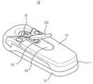
Translated fromKorean도 1은 본 발명의 바람직한 실시 예에 따른 휴대용 단말기의 배터리 팩 락킹 장치를 나타내는 분리 사시도,1 is an exploded perspective view showing a battery pack locking device of a portable terminal according to an embodiment of the present invention;
도 2는 도 1에 도시된 배터리 팩 락킹 장치를 나타내는 조립 사시도,FIG. 2 is an assembled perspective view illustrating the battery pack locking device shown in FIG. 1;
도 3은 도 2에 도시된 배터리 팩 락킹 장치를 일방향으로 절개하여 나타내는 사시도,3 is a perspective view showing the battery pack locking device shown in FIG. 2 by cutting in one direction;
도 4는 도 2에 도시된 배터리 팩 락킹 장치를 다른 방향으로 절개하여 나타내는 사시도,4 is a perspective view illustrating the battery pack locking device shown in FIG. 2 by cutting in another direction;
도 5는 휴대용 단말기의 배터리 팩을 나타내는 사시도,5 is a perspective view showing a battery pack of a portable terminal,
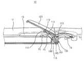
도 6은 도 1에 도시된 배터리 팩 락킹 장치가 단말기에 설치된 모습을 일부 절개하여 나타내는 사시도,FIG. 6 is a perspective view illustrating a partially cut-out view of the battery pack locking device illustrated in FIG. 1 installed in a terminal;
도 7은 도 1에 도시된 배터리 팩 락킹 장치가 단말기에 설치된 다른 모습을 일부 절개하여 나타내는 사시도,FIG. 7 is a perspective view of the battery pack locking device shown in FIG. 1 partially cut away showing another state installed in a terminal; FIG.
도 8은 도 1에 도시된 배터리 팩 락킹 장치가 작동하는 모습을 나타내는 사시도,8 is a perspective view illustrating a state in which the battery pack locking device illustrated in FIG. 1 operates;
도 9는 도 8에 도시된 배터리 팩 락킹 장치를 일부 절개하여 나타내는 사시도,FIG. 9 is a perspective view illustrating a partially cut-out of the battery pack locking device shown in FIG. 8;
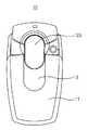
도 10과 도 11은 각각 도 1에 도시된 배터리 팩 락킹 장치를 구비하는 휴대용 단말기의 후면을 나타내는 도면.10 and 11 are rear views of a portable terminal including the battery pack locking device shown in FIG. 1, respectively.
<도면의 주요 부분의 부호에 대한 설명><Description of Signs of Major Parts of Drawings>
100 : 락킹 장치 101 : 락킹 부재100: locking device 101: locking member
102 : 커버 103 : 장착 부재102: cover 103: mounting member
104 : 구동 수단
104: drive means
본 발명은 휴대용 단말기에 관한 것으로서, 특히 휴대용 단말기의 배터리 팩 락킹 장치에 관한 것이다.The present invention relates to a portable terminal, and more particularly to a battery pack locking device of a portable terminal.
통상적으로 휴대용 단말기는 사용자와 다른 사용자 또는 사용자와 서비스 업자 사이에서 전기통신 기능을 제공하는 통신기기로서, 사용자는 휴대용 단말기를 휴대하고 다니면서 음성 통화, 단문 메시지, 멀티미디어 서비스, 엔터테인먼트 등의 다양한 서비스를 즐길 수 있다.In general, a portable terminal is a communication device that provides a telecommunication function between a user and another user or a user and a service provider, and the user can carry various services such as voice calls, short messages, multimedia services, entertainment, etc. while carrying the portable terminal. Can be.
이러한 휴대용 단말기는 외형에 따라 하나의 하우징에 송화부, 수화부, 데이터 입출력 장치 등을 하나의 하우징에 설치한 바형 단말기, 바형 단말기와 같이 하 나의 하우징에 송화부, 수화부, 데이터 입출력 장치등을 하나의 하우징에 설치하고서 키패드와 같은 데이터 입력 장치를 개폐시키는 플립 커버가 부착된 플립형 단말기, 한 쌍의 하우징이 접철 가능하게 구성되면서 송화부, 수화부, 데이터 입출력 장치들을 한 쌍의 하우징에 각각 적절하게 분산 배치한 폴더형 단말기로 분류된다.Such a portable terminal has a receiver, a receiver, and a data input / output device in one housing, such as a bar-type terminal and a bar-type terminal, in which a transmitter, a receiver, and a data input / output device are installed in one housing. Flip type terminal with flip cover for opening and closing a data input device, such as a keypad, installed in the housing, and a pair of housings are foldable so that the transmitter, the receiver, and the data input / output devices are properly distributed in the pair of housings, respectively. It is classified as one clamshell terminal.
최근에는 사용자들의 취향이 다양해지면서, 슬라이딩형, 팝업형, 스윙형 단말기들이 등장하여 상용화되고 있다. 상기와 같은 휴대용 단말기들은 당업자라면 용이하게 이해할 수 있을 것이다.Recently, as the tastes of users are diversified, sliding type, popup type, swing type terminals have been introduced and commercialized. Such portable terminals will be readily understood by those skilled in the art.
이러한 휴대용 단말기들은 전원을 공급하기 위하여, 일반적으로 휴대용 단말기의 본체 하우징의 후면에 배터리 팩이 장착된다. 휴대용 단말기는 본체 하우징 상에 장착된 배터리 팩이 이탈되는 것을 방지하기 위하여, 락킹 장치를 구비한다. 휴대용 단말기의 배터리 팩 락킹 장치는 소정의 탄성력을 제공받아 배터리 팩 장착면 상으로 돌출되는 돌기와 배터리 팩 상에 형성된 홈이 서로 맞물려 배터리 팩의 이탈을 방지하는 구성이다.In order to supply power to such portable terminals, battery packs are generally mounted on the rear of the main body housing of the portable terminal. The portable terminal has a locking device to prevent the battery pack mounted on the main body housing from being detached. The battery pack locking device of the portable terminal is configured to prevent detachment of the battery pack by receiving a predetermined elastic force and a protrusion formed on the battery pack mounting surface and a groove formed on the battery pack mesh with each other.
또한, 최근에는 휴대용 단말기의 기능이 다양화되면서, 카메라 렌즈는 휴대용 단말기에 장착되는 부가적인 요소가 아닌 필수적 요소로 자리잡고 있다. 더욱이 카메라 렌즈의 성능이 향상되면서 카메라 렌즈를 사용하지 않는 동안에는 외부에 노출되지 않도록 커버 장치가 요구되고 있다.In addition, in recent years, as the functions of the portable terminal are diversified, the camera lens is becoming an essential element rather than an additional component mounted on the portable terminal. Moreover, as the performance of the camera lens is improved, a cover device is required so that the camera lens is not exposed to the outside while the camera lens is not in use.
그러나, 휴대용 단말기의 휴대성 등을 고려할 때 휴대용 단말기의 소형화가 필수적으로 요구되는 상황에서, 휴대용 단말기에 카메라 렌즈와 같은 부가장치는 단말기의 소형화에 장애가 되고 있다. 더욱이, 카메라 렌즈의 성능이 향상됨에 따 라 카메라 소자를 보호하기 위한 커버를 설치하는 것은 이러한 문제점을 더욱 심화시키게 되었다.
However, in consideration of the portability of the portable terminal, the miniaturization of the portable terminal is indispensable. In the portable terminal, an additional device such as a camera lens is an obstacle to miniaturization of the terminal. Moreover, as the performance of the camera lens is improved, installing a cover to protect the camera element has exacerbated this problem.
상기와 같은 문제점을 해결하기 위하여, 본 발명의 목적은 배터리 팩 락킹 장치와 카메라 소자 보호를 위한 커버를 하나의 모듈 형태로 구성함으로써 단말기의 소형화에 기여할 수 있는 휴대용 단말기의 배터리 팩 락킹 장치를 제공함에 있다.In order to solve the above problems, an object of the present invention is to provide a battery pack locking device of a portable terminal that can contribute to the miniaturization of the terminal by configuring the battery pack locking device and the cover for protecting the camera element in a single module form. have.
상기와 같은 목적을 달성하기 위하여, 본 발명은 휴대용 단말기의 배터리 팩 락킹 장치에 있어서,In order to achieve the above object, the present invention provides a battery pack locking device of a portable terminal,
상기 단말기 상에 회동 가능하게 결합되고, 일방향으로 연장되어 상기 단말기 상에 장착된 배터리 팩을 가압하는 락킹 플레이트를 포함하는 락킹 부재;A locking member rotatably coupled to the terminal, the locking member including a locking plate extending in one direction to press a battery pack mounted on the terminal;
상기 락킹 플레이트가 상기 배터리 팩을 가압하는 방향으로 상기 락킹 부재를 회동시키는 탄성력을 제공하는 탄성 부재; 및An elastic member for providing an elastic force to rotate the locking member in a direction in which the locking plate presses the battery pack; And
상기 락킹 부재에 슬라이딩 이동 가능하게 결합되는 커버를 포함하는 휴대용 단말기의 배터리 팩 락킹 장치를 개시한다.
Disclosed is a battery pack locking device of a portable terminal including a cover coupled to the locking member to be slidably movable.
이하 본 발명의 바람직한 실시 예를 첨부된 도면을 참조하여 상세히 설명하면 다음과 같다. 본 발명을 설명함에 있어서, 관련된 공지기능 혹은 구성에 대한 구체적인 설명이 본 발명의 요지를 불필요하게 흐릴 수 있다고 판단되는 경우 그 상세한 설명을 생략한다.Hereinafter, exemplary embodiments of the present invention will be described in detail with reference to the accompanying drawings. In the following description of the present invention, if it is determined that the detailed description of the related known function or configuration may unnecessarily obscure the subject matter of the present invention, the detailed description thereof will be omitted.
도 1은 본 발명의 바람직한 실시 예에 따른 휴대용 단말기의 배터리 팩 락킹 장치(100)를 나타내는 분리 사시도이고, 도 2는 도 1에 도시된 배터리 팩 락킹 장치(100)를 나타내는 조립 사시도이며, 도 3은 도 2에 도시된 배터리 팩 락킹 장치(100)를 일방향으로 절개하여 나타내는 사시도이고, 도 4는 도 2에 도시된 배터리 팩 락킹 장치(100)를 다른 방향으로 절개하여 나타내는 사시도이다.1 is an exploded perspective view illustrating a battery
도 1 내지 도 4에 도시된 바와 같이, 본 발명의 바람직한 실시 예에 따른 휴대용 단말기의 배터리 팩 락킹 장치(100)는 락킹 부재(101), 커버(102), 장착 부재(103) 및 구동 수단(104)을 구비한다.1 to 4, the battery
상기 락킹 부재(101)는 상기 장착 부재(103)를 통해 휴대용 단말기(10; 도 8에 도시됨) 상에 회동 가능하게 결합된다. 상기 락킹 부재(100)는 일방향으로 연장되어 단말기(10)의 배터리 팩 장착면 상에 위치되는 락킹 플레이트(111)를 구비하고, 소정의 탄성력을 제공받아 상기 락킹 플레이트(111)가 배터리 팩 장착면에 근접하는 방향으로 회동하게 된다. 상기 락킹 플레이트(111)를 회동시키는 탄성력을 제공받기 위하여, 상기 락킹 부재(101)는 상기 락킹 플레이트(111)와는 다른 방향으로 연장되는 구동 플레이트(113)를 구비한다. 상기 락킹 플레이트(111)와 구동 플레이트(113) 사이에 회동핀(199)이 결합되어 상기 락킹 부재(101)의 회전축을 제공하게 된다. 상기 락킹 플레이트(111)와 구동 플레이트(113)는 평행하게 연장되는 구성이다.The
상기 락킹 플레이트(111)의 일면에는 적어도 하나 이상, 바람직하게는 한 쌍의 락킹 홈(112)이 형성되어 있다. 상기 락킹 플레이트(111)는 단말기(10)에 밀착되는 방향으로 단말기(10) 상에 장착된 배터리 팩(11; 도 8에 도시됨)의 외주면을 가압하게 된다. 도 5를 참조하면, 상기 락킹 장치(100)가 구비된 휴대용 단말기(10)에 장착되는 배터리 팩(11)의 외주면에는 소정 깊이로 함몰된 슬라이딩 홈(13)과, 상기 슬라이딩 홈(13) 상에 돌출된 락킹 돌기(15)들을 구비한다. 상기 배터리 팩(15)이 상기 단말기(10) 상에 장착되면, 상기 슬라이딩 홈(13) 내에서 상기 커버(102)가 슬라이딩 이동하게 되고, 상기 락킹 홈(112)들이 상기 락킹 돌기(15)들과 맞물리게 된다. 상기 배터리 팩(11)은 단말기(10)의 배터리 장착면에 밀착된 후 일정 구간만큼 슬라이딩 이동하여 결합되는 형태로서, 그의 양 측단에는 적어도 하나 이상의 결합리브(17)가 형성되어 있다. 상기 결합리브(17)는 상기 단말기(10) 상에 형성된 결합리브(미도시)들과 맞물려 배터리 팩(11)을 고정시킨다. 또한, 상기 배터리 팩(11)이 상기 단말기(10) 상에 완전히 결합되면, 상기 락킹 플레이트(111)는 상기 배터리 팩(11)의 외주면을 가압함과 동시에 상기 락킹 홈(112)들과 락킹 돌기(15)들이 서로 맞물려 상기 배터리 팩(11)을 단말기 상에 밀착시키면서 상기 배터리 팩(11)이 슬라이딩 이동하는 것을 제한한다.At least one, preferably a pair of
또한, 상기 락킹 부재(101)는 상기 락킹 플레이트(111)와 구동 플레이트(113) 사이에서 그들과 수직하는 방향으로 연장되는 종동 플레이트(115)를 구비한다. 상기 종동 플레이트(115)는 상기 락킹 부재(101)가 회동함에 따라 상기 단말기(10) 상에 장착된 배터리 팩(11)에 간섭되어 상기 배터리 팩(11)을 슬라이딩 이동 시키게 된다.In addition, the
상기 커버(102)는 상기 락킹 부재(101) 상에 슬라이딩 이동 가능하게 결합되는 슬라이딩 플레이트(121)와 상기 슬라이딩 플레이트(121)에 고정되는 커버 플레이트(123)로 구성된다. 상기 슬라이딩 플레이트(121)는 알파벳 'U'자 형상으로 그의 내측에는 길이방향으로 연장된 가이드 리브(125)가 형성되어 있다. 상기 락킹 플레이트(111)의 양 측면에는 가이드 홈(117)이 형성되어, 도 4에 도시된 바와 같이 상기 가이드 리브(125)와 가이드 홈(117)이 슬라이딩 이동 가능하게 맞물리게 된다. 따라서, 상기 슬라이딩 플레이트(121)는 상기 락킹 플레이트(111)의 양측면을 감싸는 형태로 결합되어 상기 락킹 플레이트(111) 상에서 길이방향으로 슬라이딩 이동하게 되는 것이다.The
상기 커버 플레이트(123)는 상기 슬라이딩 플레이트(121)에 고정되어 상기 락킹 플레이트(111), 슬라이딩 플레이트(121)가 외부로 노출되는 것을 차단하고, 단말기 외관을 미려하게 한다.The
상기 배터리 팩(11)이 단말기에 장착된 상태에서, 상기와 같이 구성된 커버(102)는 상기 슬라이딩 홈(13) 내에서 슬라이딩 이동할 수 있다. 상기 단말기(10) 상에서 슬라이딩 이동함에 따라, 상기 커버(102)는 상기 슬라이딩 홈(13) 내에 위치하거나 그의 일부분은 상기 단말기(10)의 외주면 일부분을 개폐시키게 된다.In a state in which the
상기 장착 부재(103)는 상기 단말기(10) 상에 고정되고, 상기 락킹 부재(101)의 양측을 회동 가능하게 지지하는 한 쌍의 지지돌기(131)들이 형성되어 있다. 즉, 상기 장착 부재(103)는 상기 락킹 부재(101)를 상기 단말기(10) 상에 회동 가능하게 결합시키는 것이다. 상기 장착 부재(103)는 상기 단말기(10) 상에 일체형으로 형성될 수 있으나, 본 발명의 바람직한 실시 예에서는 상기 락킹 장치(100)를 하나의 모듈 형태로 제작하기 위하여 단말기와 별도로 상기 장착 부재(103)가 제작되었다. 따라서, 상기 장착 부재(103)에는 단말기에 결합시키기 위한 체결편(139)이 형성되어 있다.The mounting
상기 지지돌기(131)들은 서로 마주보게 형성되고, 상기 락킹 부재(101)가 그 사이에 위치된다. 상기 지지돌기(131)들과 락킹 부재(101)는 각각 일직선 상에 정렬되는 회동홀들(119, 133)이 형성되고, 길이방향으로 연장된 회동핀(199)이 상기 회동홀들(199, 133)을 관통하게 결합된다. 따라서, 상기 락킹 부재(101)는 상기 회동핀(199)을 회전축으로 회동하게 된다. 상기 락킹 부재(101)에 형성된 회동홀(119)은 상기 락킹 플레이트(111)와 구동 플레이트(113) 사이에 형성되어, 상기 구동 플레이트(113)에 탄성력이 작용하여 상기 회동핀(199)을 중심으로 회동함에 따라 상기 락킹 플레이트(111)도 회동하게 되는 것이다.The support protrusions 131 are formed to face each other, and the locking
상기 장착 부재(103)에는 수용홈(135)이 형성되어 상기 구동 수단(104)이 수용된다. 상기 수용홈(135)의 개방된 단부는 상기 구동 플레이트(113)와 대면하게 된다.An
상기 구동 수단(113)은 탄성 부재(141)와, 구동 버튼(143)으로 구성된다. 상기 탄성 부재(141)는 상기 수용홈(135)에 수용되어 그의 일단이 상기 구동 버튼(143)을 통해 상기 구동 플레이트(113)에 지지된다. 상기 탄성 부재(141)는 압축 코일 스프링으로 구성되어, 그의 탄성력은 상기 락킹 플레이트(111)가 상기 단말기 (10)의 배터리 팩 장착면에 근접하는 방향으로 작용하게 된다.The driving means 113 is composed of an
상기 구동 버튼(143)은 상기 탄성 부재(141)가 상기 수용홈(135)의 내벽 등에 간섭되지 않고, 상기 구동 플레이트(113)에 탄성력을 원활하게 제공하게 하는 구성요소이다. 상기 탄성 부재(141)가 상기 수용홈(135)의 내벽에 간섭되지 않게 구성된다면, 상기 구동 버튼(143)은 설치되지 않을 수 있다. 상기 구동 버튼(143)은 상기 수용홈(135)의 개방된 단부에서 상기 탄성 부재(141)의 탄성력을 제공받아 상기 장착 부재(103) 상으로 출몰하게 된다.The
도 6과 도 7은 상기 락킹 장치(100)가 상기 단말기(10)에 설치된 모습을 일부 절개하여 각각 나타내는 사시도이고. 상기 락킹 장치(100)의 커버(102)가 상기 단말기(10)의 외주면 일부분을 개폐시키는 모습이 도 10과 도 11에 각각 도시된다. 도 6과 도 7에 도시된 바와 같이, 상기 탄성 부재(141)의 탄성력을 제공받아 상기 락킹 플레이트(111)가 가압함에 따라 상기 단말기(10) 상에 장착된 배터리 팩(11)은 상기 단말기(10)에 밀착되고, 상기 락킹 돌기(15)와 락킹 홈(112)이 서로 맞물려 상기 배터리 팩(10)의 슬라이딩 이동이 제한된다. 또한, 상기 배터리 팩(10)의 양 측면에 형성된 결합리브(17)들과 단말기 상에 형성된 결합리브(미도시)들이 서로 맞물려 상기 배터리 팩(11)이 상기 단말기(10)로부터 이탈하는 것이 제한된다.6 and 7 are perspective views respectively showing a part of the
상기 배터리 팩(11)을 단말기로부터 분리하기 위해서는 상기 결합리브(17)들의 결합 상태가 해제되어야 한다. 또한, 상기 결합리브(17)들의 결합 상태가 해제되기 위해서는 상기 배터리 팩(11)이 상기 단말기(10) 상에서 슬라이딩 이동하여야 하는데, 상기 락킹 돌기(15)와 락킹 홈(112)이 서로 맞물려 이를 제한하고 있는 것 이다.In order to separate the
한편, 상기 휴대용 단말기(10)는 상기 배터리 팩(11)이 장착되는 면에 인접하게 설치된 카메라 렌즈(19)를 구비한다. 이때, 상기 카메라 렌즈(19)가 백만 화소 급 이상의 고성능 카메라 소자를 채용하고 있다면, 상기 카메라 렌즈(19)를 사용하지 않을 때에는 상기 카메라 렌즈(19)를 폐쇄시켜 카메라 소자가 외부로 노출되는 것을 차단하는 것이 바람직하다.Meanwhile, the
여기서, 상기 커버(102)는 상기 락킹 플레이트(111) 상에서 슬라이딩 이동함에 따라, 상기 단말기(10)의 외주면 일부분을 개폐시키게 된다. 상기 카메라 렌즈(19)는 상기 커버(102)에 의해 개폐되는 상기 단말기(10)의 외주면에 설치되어, 도 6에 도시된 바와 같이, 상기 카메라 렌즈(19)를 사용하지 않는 동안에는 상기 커버에 의해 외부와 차단된다.Here, as the
또한, 상기 커버(102)가 상기 카메라 렌즈(19)를 페쇄시킨 상태에서, 상기 락킹 부재(101)의 회동은 제한된다. 즉, 상기 커버(102)가 상기 카메라 렌즈(19)를 폐쇄시킨 상태에서는 상기 커버(19)가 상기 단말기(10)의 외주면에 간섭되어 상기 락킹 부재(101)가 회동할 수 없는 것이다.In addition, the rotation of the locking
도 7에 도시된 바와 같이, 상기 커버(102)가 상기 슬라이딩 홈(13) 내에 위치된 상태에서, 상기 카메라 렌즈(19)가 개방된다. 따라서, 사용자는 상기 카메라 렌즈(19)를 이용한 촬영을 실시할 수 있게 된다. 또한, 상기 커버(102)가 상기 슬라이딩 홈(13) 내에 위치되면, 상기 커버(102)는 상기 단말기(10)에 간섭되지 않기 때문에 상기 락킹 부재(101)가 회동할 수 있다.As shown in FIG. 7, with the
도 8과 도 9는 상기 락킹 부재(101)를 회동시켜 상기 배터리 팩(11)을 단말기로부터 분리하는 모습이 각각 도시되어 있다.8 and 9 illustrate the state where the
도 8과 도 9에 도시된 바와 같이, 상기 배터리 팩(11)을 단말기로부터 분리하기 위해서, 사용자는 상기 락킹 플레이트(111)가 상기 배터리 팩(11)의 외주면으로부터 멀어지는 방향으로 상기 락킹 부재(101)를 회동시키게 된다. 도 8을 참조하면, 상기 단말기(10)는 본체 하우징(1)과 서브 하우징(2)을 구비하는 폴더형 단말기를 개시하고 있다. 다만, 본 발명에 따른 배터리 팩 락킹 장치(100)는 슬라이딩형, 바형, 플립형 단말기 등 배터리 팩을 장착하는 다른 어떠한 형태의 단말기에도 적용될 수 있음은 자명하다.8 and 9, in order to separate the
상기 락킹 부재(101)가 회동하면, 상기 락킹 홈(112)과 락킹 돌기(15)가 분리되고, 상기 종동 플레이트(115)는 상기 배터리 팩(11)의 일단에 간섭되어 상기 배터리 팩(11)을 슬라이딩 이동시킨다.When the locking
상기 종동 플레이트(115)에 의해 상기 배터리 팩(11)이 슬라이딩 이동하면, 상기 결합리브(17)들의 결합 상태가 해제되면서 사용자는 상기 배터리 팩(11)을 상기 단말기(10)로부터 분리시킬 수 있다.When the
한편, 상기 락킹 부재(101)가 회동함에 따라 상기 구동 플레이트(113)는 상기 구동 버튼(143)을 눌러 상기 수용홈(135) 내로 후퇴시키게 된다. 따라서, 상기 탄성 부재(141)에는 소정의 탄성력이 축적되며, 상기 탄성 부재(141)에 축적되는 탄성력은 상기 락킹 플레이트(111)가 상기 단말기(10)에 근접하는 방향으로 작용하게 된다. 따라서, 사용자가 상기 커버(012) 또는 락킹 플레이트(111)를 회동시키는 힘을 제거하면, 상기 락킹 부재(101)는 상기 구동 수단(104)의 탄성력을 제공받아 상기 락킹 플레이트(111)가 단말기에 근접하는 방향으로 회동하게 된다.On the other hand, as the locking
이상, 본 발명의 상세한 설명에서는 구체적인 실시 예에 관해서 설명하였으나, 본 발명의 범위에서 벗어나지 않는 한도 내에서 여러 가지 변형이 가능함은 당해 분야에서 통상의 지식을 가진 자에게 있어서 자명하다 할 것이다.
In the foregoing detailed description of the present invention, specific embodiments have been described. However, it will be apparent to those skilled in the art that various modifications can be made without departing from the scope of the present invention.
상술한 바와 같이, 본 발명에 따른 휴대용 단말기의 배터리 팩 락킹 장치는 단말기 상에서 회동 가능하게 결합되어 소정의 탄성력을 제공받아 배터리 팩의 외주면을 가압하는 락킹 부재와 락킹 부재 상에 슬라이딩 이동 가능하게 결합되는 커버를 구비함으로써, 배터리 팩을 견고하게 고정시킴과 동시에 단말기의 외주면 일부분을 개폐시키게 구성됨으로써 카메라 렌즈 등을 보호할 수 있게 된다. 즉, 본 발명은 배터리 팩 락킹 장치에 카메라 렌즈의 커버를 하나의 모듈 형태로 구성시킴으로써 단말기 상에서 실장 공간을 효율적으로 사용 가능하게 됨으로써 단말기의 소형화에 기여하게 되었다.As described above, the battery pack locking device of the portable terminal according to the present invention is rotatably coupled on the terminal is provided with a predetermined elastic force is coupled to the locking member and the sliding member on the locking member for pressing the outer peripheral surface of the battery pack. By providing a cover, the battery pack is firmly fixed and a part of the outer circumferential surface of the terminal is opened and closed to protect the camera lens. That is, the present invention contributes to the miniaturization of the terminal by efficiently using the mounting space on the terminal by configuring the cover of the camera lens in a module form in the battery pack locking device.
Claims (14)
Translated fromKoreanPriority Applications (3)
| Application Number | Priority Date | Filing Date | Title |
|---|---|---|---|
| KR1020040112969AKR100689510B1 (en) | 2004-12-27 | 2004-12-27 | Battery pack locking device for portable terminals |
| US11/243,077US20060138999A1 (en) | 2004-12-27 | 2005-10-04 | Battery pack locking device of a portable terminal |
| CN200510115679XACN1797965B (en) | 2004-12-27 | 2005-11-08 | Battery Pack Locking Device for Portable Terminals |
Applications Claiming Priority (1)
| Application Number | Priority Date | Filing Date | Title |
|---|---|---|---|
| KR1020040112969AKR100689510B1 (en) | 2004-12-27 | 2004-12-27 | Battery pack locking device for portable terminals |
Publications (2)
| Publication Number | Publication Date |
|---|---|
| KR20060074267A KR20060074267A (en) | 2006-07-03 |
| KR100689510B1true KR100689510B1 (en) | 2007-03-02 |
Family
ID=36610679
Family Applications (1)
| Application Number | Title | Priority Date | Filing Date |
|---|---|---|---|
| KR1020040112969AExpired - Fee RelatedKR100689510B1 (en) | 2004-12-27 | 2004-12-27 | Battery pack locking device for portable terminals |
Country Status (3)
| Country | Link |
|---|---|
| US (1) | US20060138999A1 (en) |
| KR (1) | KR100689510B1 (en) |
| CN (1) | CN1797965B (en) |
Families Citing this family (1)
| Publication number | Priority date | Publication date | Assignee | Title |
|---|---|---|---|---|
| KR100751942B1 (en) | 2006-01-06 | 2007-08-24 | 엘지전자 주식회사 | Camera lens switch |
Citations (1)
| Publication number | Priority date | Publication date | Assignee | Title |
|---|---|---|---|---|
| KR20030091336A (en)* | 2002-05-27 | 2003-12-03 | 엘지전자 주식회사 | A battery locker of mobile phone |
Family Cites Families (7)
| Publication number | Priority date | Publication date | Assignee | Title |
|---|---|---|---|---|
| US20030122957A1 (en)* | 2001-12-31 | 2003-07-03 | Emme Niels Peter | Mobile terminal with digital camera and method of capturing images |
| US7403802B2 (en)* | 2002-04-11 | 2008-07-22 | Lg Electronics Inc. | Battery and battery locking unit of mobile terminal |
| US7476462B2 (en)* | 2002-08-24 | 2009-01-13 | Samsung Electronics Co., Ltd | Battery pack locking device for portable wireless terminal |
| JP4007199B2 (en)* | 2003-01-16 | 2007-11-14 | ソニー株式会社 | Information terminal equipment |
| CN1520128A (en)* | 2003-01-24 | 2004-08-11 | 华冠通讯股份有限公司 | Buckle structure of the battery holder |
| KR100469438B1 (en)* | 2003-03-25 | 2005-02-02 | 엘지전자 주식회사 | Battery cover locking apparatus for potable phone |
| DE602004013482D1 (en)* | 2003-03-25 | 2008-06-19 | Lg Electronics Inc | locking mechanism |
- 2004
- 2004-12-27KRKR1020040112969Apatent/KR100689510B1/ennot_activeExpired - Fee Related
- 2005
- 2005-10-04USUS11/243,077patent/US20060138999A1/ennot_activeAbandoned
- 2005-11-08CNCN200510115679XApatent/CN1797965B/ennot_activeExpired - Fee Related
Patent Citations (1)
| Publication number | Priority date | Publication date | Assignee | Title |
|---|---|---|---|---|
| KR20030091336A (en)* | 2002-05-27 | 2003-12-03 | 엘지전자 주식회사 | A battery locker of mobile phone |
Also Published As
| Publication number | Publication date |
|---|---|
| CN1797965B (en) | 2010-06-16 |
| KR20060074267A (en) | 2006-07-03 |
| CN1797965A (en) | 2006-07-05 |
| US20060138999A1 (en) | 2006-06-29 |
Similar Documents
| Publication | Publication Date | Title |
|---|---|---|
| KR100640380B1 (en) | Swing type portable terminal | |
| KR100313144B1 (en) | Watch type portable radiotelephone | |
| US8192861B2 (en) | Battery cover fixing means for portable terminal | |
| KR100735305B1 (en) | Sliding module for sliding type mobile phone and cover apparatus for external card therewith | |
| KR100827082B1 (en) | Portable terminal | |
| US7859585B2 (en) | Portable terminal having camera lens assembly | |
| CN100433567C (en) | Portable communication apparatus having triple-axis hinge folder and rotation locking device thereof | |
| KR100547726B1 (en) | Rotation stop device of portable wireless terminal folder | |
| KR100800662B1 (en) | Battery cover device of portable terminal | |
| KR100689510B1 (en) | Battery pack locking device for portable terminals | |
| KR100810229B1 (en) | Hinge guide device of swing type portable terminal | |
| KR100350478B1 (en) | Hinge device for portable radiotelephone | |
| KR100298355B1 (en) | Hinge mechanism for flip-type portable telephone | |
| KR20090006372A (en) | Portable electronic devices with multifunctional cover | |
| KR100800828B1 (en) | Portable terminal having a battery cover device | |
| KR20060068244A (en) | A mobile communication terminal having an internal insertable battery including a push-type locking device | |
| KR200292164Y1 (en) | Mobile phone which having CCD camera | |
| KR100640370B1 (en) | Hinge device of a portable terminal | |
| KR101042784B1 (en) | Camera lens assembly and portable terminal having same | |
| KR200402969Y1 (en) | Interface connector cover opening and shutting apparatus for mobile phone | |
| KR100689529B1 (en) | Camera lens assembly in portable terminal | |
| KR200306380Y1 (en) | Rotary hinge module for portable radiotelephone | |
| KR101171395B1 (en) | Handheld terminal | |
| KR20010028307A (en) | Hinge device of mobile phone | |
| KR20060020869A (en) | Sliding Module of Portable Terminal |
Legal Events
| Date | Code | Title | Description |
|---|---|---|---|
| PA0109 | Patent application | St.27 status event code:A-0-1-A10-A12-nap-PA0109 | |
| A201 | Request for examination | ||
| PA0201 | Request for examination | St.27 status event code:A-1-2-D10-D11-exm-PA0201 | |
| PN2301 | Change of applicant | St.27 status event code:A-3-3-R10-R13-asn-PN2301 St.27 status event code:A-3-3-R10-R11-asn-PN2301 | |
| PN2301 | Change of applicant | St.27 status event code:A-3-3-R10-R13-asn-PN2301 St.27 status event code:A-3-3-R10-R11-asn-PN2301 | |
| PG1501 | Laying open of application | St.27 status event code:A-1-1-Q10-Q12-nap-PG1501 | |
| D13-X000 | Search requested | St.27 status event code:A-1-2-D10-D13-srh-X000 | |
| D14-X000 | Search report completed | St.27 status event code:A-1-2-D10-D14-srh-X000 | |
| E902 | Notification of reason for refusal | ||
| PE0902 | Notice of grounds for rejection | St.27 status event code:A-1-2-D10-D21-exm-PE0902 | |
| P11-X000 | Amendment of application requested | St.27 status event code:A-2-2-P10-P11-nap-X000 | |
| P13-X000 | Application amended | St.27 status event code:A-2-2-P10-P13-nap-X000 | |
| E701 | Decision to grant or registration of patent right | ||
| PE0701 | Decision of registration | St.27 status event code:A-1-2-D10-D22-exm-PE0701 | |
| GRNT | Written decision to grant | ||
| PR0701 | Registration of establishment | St.27 status event code:A-2-4-F10-F11-exm-PR0701 | |
| PR1002 | Payment of registration fee | St.27 status event code:A-2-2-U10-U11-oth-PR1002 Fee payment year number:1 | |
| PG1601 | Publication of registration | St.27 status event code:A-4-4-Q10-Q13-nap-PG1601 | |
| LAPS | Lapse due to unpaid annual fee | ||
| PC1903 | Unpaid annual fee | St.27 status event code:A-4-4-U10-U13-oth-PC1903 Not in force date:20100224 Payment event data comment text:Termination Category : DEFAULT_OF_REGISTRATION_FEE | |
| PC1903 | Unpaid annual fee | St.27 status event code:N-4-6-H10-H13-oth-PC1903 Ip right cessation event data comment text:Termination Category : DEFAULT_OF_REGISTRATION_FEE Not in force date:20100224 | |
| R18-X000 | Changes to party contact information recorded | St.27 status event code:A-5-5-R10-R18-oth-X000 |