KR100685152B1 - Information processing device - Google Patents
Information processing deviceDownload PDFInfo
- Publication number
- KR100685152B1 KR100685152B1KR1019990025114AKR19990025114AKR100685152B1KR 100685152 B1KR100685152 B1KR 100685152B1KR 1019990025114 AKR1019990025114 AKR 1019990025114AKR 19990025114 AKR19990025114 AKR 19990025114AKR 100685152 B1KR100685152 B1KR 100685152B1
- Authority
- KR
- South Korea
- Prior art keywords
- image pickup
- display unit
- information processing
- lens
- processing apparatus
- Prior art date
- Legal status (The legal status is an assumption and is not a legal conclusion. Google has not performed a legal analysis and makes no representation as to the accuracy of the status listed.)
- Expired - Fee Related
Links
Images


Classifications
- G—PHYSICS
- G06—COMPUTING OR CALCULATING; COUNTING
- G06F—ELECTRIC DIGITAL DATA PROCESSING
- G06F1/00—Details not covered by groups G06F3/00 - G06F13/00 and G06F21/00
- G06F1/16—Constructional details or arrangements
- G—PHYSICS
- G06—COMPUTING OR CALCULATING; COUNTING
- G06F—ELECTRIC DIGITAL DATA PROCESSING
- G06F1/00—Details not covered by groups G06F3/00 - G06F13/00 and G06F21/00
- G06F1/16—Constructional details or arrangements
- G06F1/1613—Constructional details or arrangements for portable computers
- G06F1/1633—Constructional details or arrangements of portable computers not specific to the type of enclosures covered by groups G06F1/1615 - G06F1/1626
- G06F1/1684—Constructional details or arrangements related to integrated I/O peripherals not covered by groups G06F1/1635 - G06F1/1675
- G06F1/169—Constructional details or arrangements related to integrated I/O peripherals not covered by groups G06F1/1635 - G06F1/1675 the I/O peripheral being an integrated pointing device, e.g. trackball in the palm rest area, mini-joystick integrated between keyboard keys, touch pads or touch stripes
- F—MECHANICAL ENGINEERING; LIGHTING; HEATING; WEAPONS; BLASTING
- F16—ENGINEERING ELEMENTS AND UNITS; GENERAL MEASURES FOR PRODUCING AND MAINTAINING EFFECTIVE FUNCTIONING OF MACHINES OR INSTALLATIONS; THERMAL INSULATION IN GENERAL
- F16M—FRAMES, CASINGS OR BEDS OF ENGINES, MACHINES OR APPARATUS, NOT SPECIFIC TO ENGINES, MACHINES OR APPARATUS PROVIDED FOR ELSEWHERE; STANDS; SUPPORTS
- F16M11/00—Stands or trestles as supports for apparatus or articles placed thereon ; Stands for scientific apparatus such as gravitational force meters
- F16M11/02—Heads
- F16M11/04—Means for attachment of apparatus; Means allowing adjustment of the apparatus relatively to the stand
- F16M11/06—Means for attachment of apparatus; Means allowing adjustment of the apparatus relatively to the stand allowing pivoting
- F16M11/10—Means for attachment of apparatus; Means allowing adjustment of the apparatus relatively to the stand allowing pivoting around a horizontal axis
- F—MECHANICAL ENGINEERING; LIGHTING; HEATING; WEAPONS; BLASTING
- F16—ENGINEERING ELEMENTS AND UNITS; GENERAL MEASURES FOR PRODUCING AND MAINTAINING EFFECTIVE FUNCTIONING OF MACHINES OR INSTALLATIONS; THERMAL INSULATION IN GENERAL
- F16M—FRAMES, CASINGS OR BEDS OF ENGINES, MACHINES OR APPARATUS, NOT SPECIFIC TO ENGINES, MACHINES OR APPARATUS PROVIDED FOR ELSEWHERE; STANDS; SUPPORTS
- F16M11/00—Stands or trestles as supports for apparatus or articles placed thereon ; Stands for scientific apparatus such as gravitational force meters
- F16M11/02—Heads
- F16M11/04—Means for attachment of apparatus; Means allowing adjustment of the apparatus relatively to the stand
- F16M11/06—Means for attachment of apparatus; Means allowing adjustment of the apparatus relatively to the stand allowing pivoting
- F16M11/12—Means for attachment of apparatus; Means allowing adjustment of the apparatus relatively to the stand allowing pivoting in more than one direction
- F16M11/14—Means for attachment of apparatus; Means allowing adjustment of the apparatus relatively to the stand allowing pivoting in more than one direction with ball-joint
- F—MECHANICAL ENGINEERING; LIGHTING; HEATING; WEAPONS; BLASTING
- F16—ENGINEERING ELEMENTS AND UNITS; GENERAL MEASURES FOR PRODUCING AND MAINTAINING EFFECTIVE FUNCTIONING OF MACHINES OR INSTALLATIONS; THERMAL INSULATION IN GENERAL
- F16M—FRAMES, CASINGS OR BEDS OF ENGINES, MACHINES OR APPARATUS, NOT SPECIFIC TO ENGINES, MACHINES OR APPARATUS PROVIDED FOR ELSEWHERE; STANDS; SUPPORTS
- F16M13/00—Other supports for positioning apparatus or articles; Means for steadying hand-held apparatus or articles
- F16M13/005—Other supports for positioning apparatus or articles; Means for steadying hand-held apparatus or articles integral with the apparatus or articles to be supported
- G—PHYSICS
- G06—COMPUTING OR CALCULATING; COUNTING
- G06F—ELECTRIC DIGITAL DATA PROCESSING
- G06F1/00—Details not covered by groups G06F3/00 - G06F13/00 and G06F21/00
- G06F1/16—Constructional details or arrangements
- G06F1/1613—Constructional details or arrangements for portable computers
- G06F1/1615—Constructional details or arrangements for portable computers with several enclosures having relative motions, each enclosure supporting at least one I/O or computing function
- G06F1/1616—Constructional details or arrangements for portable computers with several enclosures having relative motions, each enclosure supporting at least one I/O or computing function with folding flat displays, e.g. laptop computers or notebooks having a clamshell configuration, with body parts pivoting to an open position around an axis parallel to the plane they define in closed position
- G—PHYSICS
- G06—COMPUTING OR CALCULATING; COUNTING
- G06F—ELECTRIC DIGITAL DATA PROCESSING
- G06F1/00—Details not covered by groups G06F3/00 - G06F13/00 and G06F21/00
- G06F1/16—Constructional details or arrangements
- G06F1/1613—Constructional details or arrangements for portable computers
- G06F1/1633—Constructional details or arrangements of portable computers not specific to the type of enclosures covered by groups G06F1/1615 - G06F1/1626
- G06F1/1675—Miscellaneous details related to the relative movement between the different enclosures or enclosure parts
- G06F1/1679—Miscellaneous details related to the relative movement between the different enclosures or enclosure parts for locking or maintaining the movable parts of the enclosure in a fixed position, e.g. latching mechanism at the edge of the display in a laptop or for the screen protective cover of a PDA
- G—PHYSICS
- G06—COMPUTING OR CALCULATING; COUNTING
- G06F—ELECTRIC DIGITAL DATA PROCESSING
- G06F1/00—Details not covered by groups G06F3/00 - G06F13/00 and G06F21/00
- G06F1/16—Constructional details or arrangements
- G06F1/1613—Constructional details or arrangements for portable computers
- G06F1/1633—Constructional details or arrangements of portable computers not specific to the type of enclosures covered by groups G06F1/1615 - G06F1/1626
- G06F1/1684—Constructional details or arrangements related to integrated I/O peripherals not covered by groups G06F1/1635 - G06F1/1675
- G06F1/1686—Constructional details or arrangements related to integrated I/O peripherals not covered by groups G06F1/1635 - G06F1/1675 the I/O peripheral being an integrated camera
- H—ELECTRICITY
- H04—ELECTRIC COMMUNICATION TECHNIQUE
- H04N—PICTORIAL COMMUNICATION, e.g. TELEVISION
- H04N23/00—Cameras or camera modules comprising electronic image sensors; Control thereof
- H04N23/50—Constructional details
Landscapes
- Engineering & Computer Science (AREA)
- General Engineering & Computer Science (AREA)
- Theoretical Computer Science (AREA)
- Computer Hardware Design (AREA)
- Physics & Mathematics (AREA)
- Human Computer Interaction (AREA)
- General Physics & Mathematics (AREA)
- Mechanical Engineering (AREA)
- Mathematical Physics (AREA)
- Signal Processing (AREA)
- Multimedia (AREA)
- Studio Devices (AREA)
- Lens Barrels (AREA)
- Accessories Of Cameras (AREA)
- Control Of Transmission Device (AREA)
Abstract
Translated fromKoreanDescription
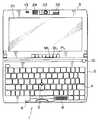
Translated fromKorean도 1은 디스플레이부가 본체에 대해 피봇팅하여(pivotally) 열릴 때 본 발명이 인가된 휴대용 개인용 컴퓨터를 도시하는 투시도.1 is a perspective view showing a portable personal computer to which the present invention is applied when the display portion is pivotally opened with respect to the main body.
도 2는 도 1에 도시된 휴대용 개인용 컴퓨터의 평면도.2 is a plan view of the portable personal computer shown in FIG.
도 3은 디스플레이부가 본체에 대해 닫힐 때 휴대용 개인용 컴퓨터의 좌측 입면도.3 is a left side elevation view of the portable personal computer when the display portion is closed relative to the body.
도 4는 디스플레이부가 본체에 대해 180도 만큼 피봇팅하여 열릴 때 도 1의 휴대용 개인용 컴퓨터에 대한 우측 입면도.4 is a right elevational view of the portable personal computer of FIG. 1 when the display portion is pivotally opened by 180 degrees relative to the body;
도 5는 도 3에 도시된 휴대용 개인용 컴퓨터의 정면도.5 is a front view of the portable personal computer shown in FIG.
도 6은 도 4에 도시된 휴대용 개인용 컴퓨터의 하단 평면도.6 is a bottom plan view of the portable personal computer shown in FIG.
도 7은 도 1의 휴대용 개인용 컴퓨터 중 전자 회로를 도시하는 블록도.7 is a block diagram illustrating an electronic circuit of the portable personal computer of FIG. 1.
도 8a 및 도 8b는 도 1의 휴대용 개인용 컴퓨터 중 영상 픽업(image pickup)부의 설치 구조를 도시하는 부분적 투시도.8A and 8B are partial perspective views showing the installation structure of an image pickup portion of the portable personal computer of FIG. 1;
도 9a는 도 1의 휴대용 개인용 컴퓨터의 개략적인 투시도.9A is a schematic perspective view of the portable personal computer of FIG. 1.
도 9b는 도 1에 도시된 휴대용 개인용 컴퓨터 중 영상 픽업부의 단편적인 투시도.9B is a fragmentary perspective view of the image pickup unit of the portable personal computer shown in FIG. 1;
도 9c는 도 9b에 도시된 영상 픽업부의 캠(cam)을 도시하는 부분적인 투시도.FIG. 9C is a partial perspective view showing a cam of the image pickup section shown in FIG. 9B. FIG.
도 10은 도 9b에 도시된 영상 픽업부에서 화살표로 나타내진 방향으로 선 I-I'을 따라 관찰되는 도면.FIG. 10 is a view observed along the line I-I 'in the direction indicated by the arrow in the image pickup section shown in FIG. 9B;
도 11a 내지 도 11c는 도 10의 영상 픽업부의 피봇팅을 설명하는 개략적이고 부분적인 도면.11A-11C are schematic and partial views illustrating the pivoting of the image pickup section of FIG. 10.
도 11d 내지 도 11f는 각각 도 11a 내지 도 11c에 대응하는 영상 픽업부의 피봇팅을 설명하는 측면 입면도.11D to 11F are side elevation views illustrating pivoting of the image pickup section corresponding to FIGS. 11A to 11C, respectively.
도 12는 도 1의 휴대용 개인용 컴퓨터에 결합된 마이크로폰을 도시하는 개략적인 단면도.12 is a schematic cross-sectional view illustrating a microphone coupled to the portable personal computer of FIG. 1.
도 13a, 도 13b, 및 도 13c는 디스플레이부가 본체에 대해 피봇팅하여 닫힐 때 도 10의 영상 픽업부의 피봇팅을 설명하는 개략적이고 부분적인 평면도.13A, 13B, and 13C are schematic and partial plan views illustrating the pivoting of the image pickup portion of FIG. 10 when the display portion is pivoted about the main body and closed;
도 14a, 도 14b, 및 도 14c는 디스플레이부가 본체에 대해 피봇팅하여 열릴 때 도 10의 영상 픽업부의 피봇팅을 설명하는 개략적이고 부분적인 평면도.14A, 14B, and 14C are schematic, partial plan views illustrating the pivoting of the image pickup portion of FIG. 10 when the display portion is pivoted open relative to the body;
도 15는 디스플레이부가 본체에 대해 피봇팅하여 열릴 때 종래 기술의 휴대용 개인용 컴퓨터의 투시도.15 is a perspective view of a portable personal computer of the prior art as the display portion is pivoted open relative to the body.
도 16은 도 15에 도시된 휴대용 개인용 컴퓨터에 결합된 CCD 비디오 카메라의 개략적이고 부분적인 도면.FIG. 16 is a schematic and partial view of a CCD video camera coupled to the portable personal computer shown in FIG. 15.
본 발명은 정보 처리 장치에 관한 것으로, 특히 물체에 조정가능한 초점을 갖는 CCD(Charge Coupled Device) 비디오 카메라가 결합된 정보 처리 장치에 관한 것이다.The present invention relates to an information processing apparatus, and more particularly, to an information processing apparatus incorporating a Charge Coupled Device (CCD) video camera having an adjustable focus on an object.
본 특허 출원의 양수인은 예를 들면 일본 특허 공개 공보 No. 51665/1998에서 휴대용 개인용 컴퓨터에 CCD 비디오 카메라를 결합시키고, CCD 비디오 카메라에 의해 포착된 영상 데이터를 처리하고, 또한 처리된 영상 데이터를 디스플레이 유닛상에 디스플레이하는 장치를 제안하였다. 도 15 및 도 16은 문서에서 발표된 장치를 도시한다.The assignee of the present patent application is, for example, Japanese Patent Laid-Open No. In 51665/1998 a device has been proposed for coupling a CCD video camera to a portable personal computer, processing the image data captured by the CCD video camera, and also displaying the processed image data on a display unit. 15 and 16 show the device presented in the document.
먼저 도 15를 참고로, 개인용 컴퓨터(161)는 얇은 두께의 직사각형 구성을 갖는 수납기 형태의 본체부(162), 및 실질적으로 본체부(162)와 같은 크기의 수납기 형태로 형성되고 그래픽, 문자 등을 그위에 디스플레이하도록 본체부(162)상에서 피봇 개폐(pivot open and closing movement)되도록 설치된 디스플레이 패널부(165)를 포함한다. 개인용 컴퓨터(161)가 사용될 때, 디스플레이 패널부(165)는 도 15에 도시된 바와 같이, 위쪽으로 피봇팅되어 본체부(162)로부터 열리고, 개인용 컴퓨터(161)가 사용되지 않을 때는 디스플레이 패널부(165)가 아래쪽으로 피봇팅되어 본체부(162) 상에 닫힌다.First, referring to FIG. 15, a
본체부(162)는 키보드(163) 및 트랙 패드(track pad)(164)와 같이 사용자에 수동으로 동작되도록 제공된 수동 동작가능 소자를 갖는다. 데이터는 키보드(163) 및/또는 트랙 패드(164)의 동작으로 개인용 컴퓨터(161)에 입출력된다. 본체부(162)는 또한 그에 결합된 회로 보드(도시되지 않은)를 갖는다. 회로 보드는 CPU(Central Processing Unit), ROM(Read Only Memory), RAM(Random Access Memory), 및 그에 설치된 다른 요구되는 소자(도시되지 않은)를 갖는다.
디스플레이 패널부(165)는 그래픽, 문자 등을 디스플레이하도록 제공된 액정 디스플레이 유닛(166)을 갖는다. 디스플레이 패널부(165)는 또한 도 15에서 액정 디스플레이 유닛(166) 위의 중앙 위치에 형성된 설치 그루브(mounting groove)(167)를 갖고, CCD 비디오 카메라(169)는 그 설치 그루브(167)에서 슬라이딩되도록 설치된다.The
설치 그루브(167)는 상단 중앙 위치에서 디스플레이 패널부(165)의 물질을 U자형으로 부분 제거함으로서 형성된 오목한 구조를 갖는다. CCD 비디오 카메라(169)는 설치 그루브(167)에 제공된 지지 멤버(168)에 의해 지지된다. CCD 비디오 카메라(169)내의 CCD(도시되지 않은)상에 형성된 영상은 도시되지 않은 케이블을 통해 개인용 컴퓨터(161)로 인출된다.The
도 16은 특별히 CCD 비디오 카메라(169)를 도시한다. 도 16을 참고로, 디스플레이 패널부(165)에 고정된 지지 멤버(168)는 CCD 비디오 카메라(169)의 회전구(175)와 같은 곡률을 갖는 컵형태의 지지 곡면(168b)을 갖는다. 지지 멤버(168)는 회전 운동을 위해 회전구(175)를 지지하도록 지지 곡면(168b)으로 회전구(175)를 유지시킨다.16 specifically shows a
CCD 비디오 카메라(169)는 실질적으로 구형으로 형성된 카메라 본체부(171), 카메라 본체부(171)로부터 관모양으로 확장된 렌즈부(172), 카메라 본체부(171)의 일부에 연결된 회전 샤프트(turning shaft)(174), 및 회전 샤프트(174)의 다른 끝부분에 연결된 구형으로 형성된 회전구(175)를 포함한다. 케이블(173)은 카메라 본체부(171)로부터 확장되어 개인용 컴퓨터(161)의 적절한 내부 멤버에 연결된다. 카메라 본체부(171)는 회전구(175)의 중심 주위에서 미끄러지듯 이동될 수 있어, 렌즈부(172)를 통해 소정의 범위에 걸쳐 영상을 픽업(pick up)할 수 있다.The
CCD 비디오 카메라(169)는 이 방식으로 소정의 렌즈의 회전 샤프트(174)를 포함하므로, 카메라 본체(171)의 방향을 변화시키도록 카메라 본체부(171)에 힘이 인가되면, 피봇력(pivoting force)은 회전 샤프트(174)를 통해 회전구(175)로 전해진다. 다른 말로 하면, 카메라 본체(171)의 방향은 CCD 비디오 카메라(169)의 영상 픽업 범위를 적절하게 변화시키도록 회전구(175)의 중심 주위에서 변화될 수 있다. 피봇력이 인가되지 않을 때, 회전구(175)는 지지 멤버(168)에서 회전되지 않고 카메라 본체부(171)를 고정되게 지지하므로, 그에 의해 카메라 본체부(171)의 영상 픽업 방향을 유지하게 된다.Since the
그러나, 비록 상술된 개인용 컴퓨터에 결합된 CCD 카메라가 영상 픽업 범위의 적절한 변화를 허용하더라도, 영상 픽업되는 물체에 적절하게 초점을 맞추도록 허용되지 않는다는 점에서 해결될 문제점을 갖는다.However, although the CCD camera coupled to the personal computer described above allows for an appropriate change in the image pickup range, there is a problem to be solved in that it is not allowed to properly focus on the object to be picked up.
본 발명의 목적은 결합된 CCD 카메라가 물체에 적절하게 초점을 맞출 수 있는 정보 처리 장치를 제공하는 것이다.It is an object of the present invention to provide an information processing apparatus in which a combined CCD camera can properly focus on an object.
본 발명에 따라 상술된 목적을 이루기 위해, 안에 결합된 영상 픽업(image pickup) 장치를 갖는 정보 처리 장치가 제공되고, 영상 픽업 장치는 물체의 영상을 픽업하는 영상 픽업 수단, 영상 픽업 수단에 영상을 형성하기 위한 렌즈를 유지하고 톱니 모양의 원주 부분(serrated circumferential portion)을 갖는 유지 수단, 렌즈의 광학축 방향을 따라 회전될 때 유지 수단을 이동시키도록 유지 수단의 톱니 모양의 원주 부분과 맞는(fitting) 이동 수단, 및 유지 수단과 이동 수단을 수용하는 수용 수단을 포함한다.According to the present invention, an information processing apparatus having an image pickup device coupled therein is provided, and the image pickup device includes an image pickup means for picking up an image of an object and an image pickup means. Holding means for holding the lens for forming and having a serrated circumferential portion, fitting the serrated circumferential portion of the holding means to move the holding means when rotated along the optical axis direction of the lens ) Moving means, and receiving means for receiving the holding means and the moving means.
정보 처리 장치로, 유지 수단은 이동 수단을 회전시켜 렌즈의 광학축 방향으로 이동된다. 결과적으로, 렌즈의 초점이 물체에 조정될 수 있다.In the information processing apparatus, the holding means is moved in the optical axis direction of the lens by rotating the moving means. As a result, the focus of the lens can be adjusted to the object.
본 발명의 상기 목적과 다른 목적, 특성, 및 이점은 같은 부분 또는 소자를 같은 참고 번호로 나타낸 첨부된 도면과 연관되어 다음의 설명과 청구항으로부터 명백해진다.The above and other objects, features, and advantages of the present invention will become apparent from the following description and claims taken in conjunction with the accompanying drawings, in which like parts or elements are indicated by like reference numerals.
본 발명의 양호한 실시예가 설명되기 이전에, 이후 설명될 본 발명에서 실시예의 소자와 청구항에서 설명되는 다양한 특성 사이의 대응 관계를 명백히하기 위해, 본 발명의 특성은 그들을 나타내는 참고 기호가 괄호안에 부가된 대응 소자와 함께 이후 설명된다. 그러나, 이 설명은 단순한 예를 제공하는 것으로, 본 발명의 특성이 언급된 소자에 제한됨을 의미하지는 않는다.Before the preferred embodiments of the present invention have been described, in order to clarify the correspondence between the elements of the embodiments and the various properties described in the claims in the following description, the characteristics of the present invention are indicated by reference symbols indicating them in parentheses. The following will be described together with corresponding elements. However, this description provides a simple example and does not mean that the nature of the present invention is limited to the mentioned device.
청구항 1에 따른 정보 처리 장치는, 안에 결합된 영상 픽업 장치를 갖고, 이는 물체의 영상을 픽업하는 영상 픽업 수단(예를 들면, 도 9b에 도시된 CCD(114)), 영상 픽업 수단에 영상을 형상하기 위한 렌즈를 유지하고 톱니 모양의 주변 부분을 갖는 유지 수단(예를 들면, 도 9b에 도시된 렌즈-배럴(lens-barrel)부(102)), 렌즈의 광학축 방향을 따라 회전될 때 유지 수단을 이동시키도록 유지 수단의 톱니 모양의 주변 부분과 맞는 이동 수단(예를 들면, 도 9b에 도시된 초점 조정 링(focus adjustment ring:25)), 및 유지 수단과 이동 수단을 수용하는 수용 수단(예를 들면, 도 8a 및 도 8b에 도시된 CCD 비디오 카메라 유닛(101))을 포함한다.The information processing apparatus according to
다음에서는 본 발명의 양호한 실시예에 따른 정보 처리 장치가 상세히 설명된다.In the following, an information processing apparatus according to a preferred embodiment of the present invention is described in detail.
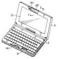
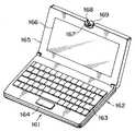
먼저 도 1 내지 도 6을 참고로, 본 발명이 적용된 휴대용 개인용 컴퓨터가 도시된다. (1)로 나타내져 일반적으로 도시된 개인용 컴퓨터는 미니 노트북형의 개인용 컴퓨터로서, 기본적인 구성성분으로 본체(2), 및 본체(2)의 후면측 방향을 따라 확장된 축을 따라 본체(2)에 대해 피봇 개폐 이동하도록 설치된 디스플레이부(3)를 포함한다. 도 2에서는 디스플레이부(3)가 본체(2)에 대해 열리고; 도 3은 본체(2)에 대해 닫힌 디스플레이부(3)를 포함한 개인용 컴퓨터(1)를 도시하는 좌측면도이고; 도 4는 본체(2)에 대해 180도 만큼 열린 디스플레이부(3)를 포함한 개인용 컴퓨터(1)를 도시하는 우측면도이고; 도 5는 도 3에 도시된 개인용 컴퓨터(1)의 상면도이고; 또한 도 6은 도 4에 도시된 개인용 컴퓨터(1)의 하면도이다.First, referring to FIGS. 1 to 6, a portable personal computer to which the present invention is applied is shown. A personal computer, generally represented and indicated by (1), is a mini notebook-type personal computer, which, as a basic component, is connected to the
키보드(4)와 트랙 포인트(상표)(5)는 본체(2)의 상단면에 설치된다. 키보드(4)는 다양한 문자, 심볼 등을 입력하도록 동작되고, 트랙 포인트(5)는 마우스 커서 등을 이동시키도록 동작된다. 또한, 사운드를 출력하는 스피커(8)와 셔터 버튼(shutter button)(10)이 본체(2)의 상단면에 제공된다. 셔터 버튼(10)은 디스플레이부(3)에 제공되는 CCD 비디오 카메라(23)를 통해 물체의 영상을 픽업하도록 동작된다.The
클로(claw)(13)는 도 1에서 디스플레이부(3)의 상단 끝부분에 제공되고, 클로(13)가 고정될 구멍(hole)(6)은 디스플레이부(3)가 도 3에 도시된 바와 같이 본체(2)에 대해 닫힐 때 클로(13)와 마주대하는 본체(2)의 위치에 개구 형태로 제공된다. 슬라이드 레버(slide lever)(7)는, 클로(13)를 고정하도록 구멍(6)에 고정시켜 디스플레이부(3)를 그 닫힌 위치에서 잠그는, 본체(2)의 정면과 평행하게 스라이딩 하도록 본체(2)의 정면의 위치에 설치된다. 클로(13)가 슬라이드 레버(7)에서 해제될 때, 디스플레이부(3)는 본체(2)에 대해 피봇팅될 수 있다. 마이크로폰(24)은 클로(13)와 인접하게 설치된다. 마이크로폰(24)은 또한 도 6에 도시된 바와 같이 개인용 컴퓨터(1)의 후면에서 사운드를 수집할 수 있다.A
또한, 프로그램가능한 전력키(programmable power key, PPK)(9)는 본체(2)의 정면에 제공된다. 도 5에 도시된 바와 같이, 배기구(exhaust hole:11)는 본체(2)의 우측면에 형성되고, 흡기구(14)는 본체(2)의 정면 하단부에 형성된다. 또한, PCMCIA(Personal Computer Memory Card International Association) 카드(PC 카드)를 수신하는 슬롯(12)은 배기구(11)의 우측에 형성된다.In addition, a programmable power key (PPK) 9 is provided in front of the
영상을 디스플레이하는 LCD(Liquid Crystal Display)(21)는 디스플레이부(3)의 정면에 제공되고, 영상 픽업부(22)는 디스플레이부(3)에 대한 피봇팅을 위해 도 1에서 LCD(21)의 상단 끝부분에 설치된다. 특별히, 영상 픽업부(22)는 LCD(21)의 방향에서 반대 방향으로 180도의 범위내에서 임의의 위치에 동조되도록 설치된다. CCD 비디오 카메라(23)는 영상 픽업부(22)에 설치된다.An LCD (Liquid Crystal Display) 21 for displaying an image is provided in front of the
발광 다이오드(LED)로 형성될 수 있는 전력 공급 램프(PL), 배터리 램프(BL), 메시지 램프(ML), 및 다른 필요한 램프는 도 1에서 본체(2)에 인접한 디스플레이부(3)의 하단 부분에 제공된다. 도 3에 도시된 참고 번호(40)는 본체(2)의 좌측면에 제공된 전력 공급 스위치를 나타내고, (25)는 CCD 비디오 카메라(23)의 초점을 조정하기 위한 조정 링을 나타냄을 주목하여야 한다. 또한, 도 6에 도시된 참고 번호(26)는 그를 통해 추가 메모리가 본체(2)에 장착될 입구에 걸쳐 덮혀있는 덮개를 나타내고, 참고 번호(41)는 덮개(26)의 고정 멈춤쇠를 푸는 핀이 삽입될 작은 구멍을 나타낸다.The power supply lamp PL, the battery lamp BL, the message lamp ML, and other necessary lamps, which may be formed of a light emitting diode LED, are shown at the bottom of the
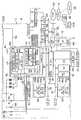
도 7은 개인용 컴퓨터(1)의 내부 구조를 도시한다. 도 7을 참고로, CPU(Central Processing Unit)(52), 필요할 때 개인용 컴퓨터(1)로 장착되는 PC 카드(53), RAM(Random Access Memory)(54), 및 그래픽 칩(81)은 내부 버스(PCI(Peripheral Component Interconnect))(51)에 연결된다. 내부 버스(51)는 외부(ISA(Industrial Standard Architecture)) 버스(55)에 연결되고, 하드 디스크 드라이브(HDD)(56), I/O(input/output) 제어기(57), 키보드 제어기(58), 트랙 포인트 제어기(59), 사운드 칩(60), LCD 제어기(83), 모뎀(50), 및 요구되는 다른 디바이스는 외부 버스(55)에 연결된다.7 shows the internal structure of the
CPU(52)는 다양한 기능을 제어하는 제어기로 동작한다. PC 카드(53)는 적절하게 선택 기능을 개인용 컴퓨터(1)에 부가하기 위해 장착된다.The
RAM(54)은 시작이 완료되는 시점에서 전자 우편 프로그램(응용 프로그램)(54A), 자동 파일럿 프로그램(응용 프로그램)(54B), 및 그에 저장된 OS(operating system)(54C)를 갖는다. 기술된 프로그램은 HDD(56)에서 RAM(54)으로 전달된다.The
전자 우편 프로그램(54A)은 전화선과 같은 통신선인 네트워크를 통해 전자 메시지를 전달 또는 전송하기 위한 프로그램이다. 전자 우편 프로그램(54A)은 들어오는 우편을 포착하는 기능을 특정한 기능으로 갖는다. 들어오는 우편을 포착하는 기능은 그 사용자에게 지정된 우편에 대해 우편 서버(93)의 우편함(93A)을 점검하고, 이와 같은 우편이 발견되는 경우 이를 포착한다.The
자동 파일럿 프로그램(54B)은 소정의 순서로 미리 설정된 다수의 처리과정(또는 프로그램)을 연속하여 시작하기 위한 프로그램이다.The auto pilot program 54B is a program for continuously starting a plurality of processes (or programs) preset in a predetermined order.
OS(기본적인 프로그램 소프트웨어)(54C)는 윈도우95(상표)로 나타내지는 컴퓨터의 기본 동작을 제어한다.The OS (basic program software) 54C controls the basic operation of the computer, represented by Windows 95 (trademark).
한편, 외부 버스측(55)의 하드 디스크 드라이브(HDD)(56)는 그에 저장된 전자 우편 프로그램(56A), 자동 파일럿 프로그램(56B), 및 OS(기본적인 프로그램 소프트웨어)(56C)를 갖는다. OS(56C), 자동 파일럿 프로그램(56B), 및 전자 우편 프로그램(56A)은 시작(부팅) 처리과정에서 연속적으로 전달되어 RAM(54)에 저장된다.On the other hand, the hard disk drive (HDD) 56 on the
I/O 제어기(57)는 I/O 인터페이스(62)로 제공된 마이크로제어기(61)를 포함한다. 마이크로제어기(61)는 I/O 인터페이스(62)에 부가하여, 서로 연결된 CPU(63), RAM(64), 및 ROM(69)을 포함한다. RAM(64)은 키(key)-입력 상태 레지스터(65), LED(light emitting diode) 제어 레지스터(66), 설정 시간 레지스터(67), 및 레지스터(68)를 포함한다. 설정 시간 레지스터(67)는 사용자에 의해 미리 설정된 시간(시작 조건)이 오면 시작 순차 제어부(76)의 동작을 개시하는데 사용된다. 레지스터(68)는 미리 설정된 동작키의 조합(시작 조건)과 시작될 응용 프로그램 사이의 대응성을 저장한다. 저장된 동작키의 조합이 사용자에 의해 입력될 때, 저장된 응용 프로그램(예를 들면, 전자 우편)이 시작된다.I /
키-입력 상태 레지스터(65)는 단일 터치 동작을 위해 프로그램가능한 전력키(PPK)(9)가 눌려질 때 동작키 플래그를 저장한다. LED 제어 레지스터(66)는 레지스터(68)에 저장된 응용 프로그램(전자 우편 프로그램)의 시작 조건을 나타내는 메시지 램프(ML)의 ON/OFF 상태를 제어한다. 설정 시간 레지스터(67)는 임의의 시간 설정을 수용한다.The key-input status register 65 stores the action key flag when the programmable power key (PPK) 9 is pressed for a single touch operation. The LED control register 66 controls the ON / OFF state of the message lamp ML indicating the start condition of the application program (e-mail program) stored in the
백업 배터리(74)는 본체(2)로의 전력 공급이 OFF 상태일 때 키-입력 상태 레지스터(65), LED 제어 레지스터(66), 및 설정 시간 레지스터(67)의 저장값들이 유지될 수 있도록 마이크로제어기(61)에 연결된다.The
마이크로제어기(61)의 ROM(69)은 그에 미리 저장된 기상 프로그램(wakeup program:70), 키-입력 모니터 프로그램(71), 및 LED 제어 프로그램(72)을 갖는다. ROM(69)은 예를 들면, EEPROM(electrically erasable and programmable read only memory)로 형성된다. EEPROM은 또한 플래쉬 메모리(flash memory)라 칭하여진다. 또한, 일반적으로 현재 시간을 카운트하는 RTC(Real-Time Clock)(75)은 마이크로제어기(61)에 연결된다.The
ROM(69)내의 기상 프로그램(70)은 설정 시간이 될 때 설정 시간 레지스터(67)에 미리 설정된 시간이 되어 소정의 처리과정(또는 프로그램)을 시작하는가 여부를 RTC(75)로부터 공급된 현재 시간 데이터를 근거로 점검하기 위한 프로그램이다. 키-입력 모니터 프로그램(71)은 일반적으로 프로그램가능한 전력키(PPK)(9)가 사용자에 의해 눌려졌는가 여부를 조사하기 위한 프로그램이다. LED 제어 프로그램(72)은 메시지 램프(ML)의 ON/OFF 상태를 제어하기 위한 프로그램이다.When the wake-up
ROM(69)은 그에 기록된 BIOS(Basic Input/Output System)(73)을 갖는다. BIOS는 기본적인 입력/출력 시스템으로, OS 또는 응용 소프트웨어와 주변 장비(디스플레이 유닛, 키보드, 하드 디스크 드라이브 등) 사이의 데이터 전달(입력/출력)을 제어하기 위한 소프트웨어 프로그램이다.
외부 버스(55)에 연결된 키보드 제어기(58)는 키보드(4)로부터의 입력을 제어한다. 트랙 포인트 제어기(59)는 트랙 포인트(5)의 입력을 제어한다.The keyboard controller 58 connected to the
사운드 칩(60)은 마이크로폰(24)으로부터 입력을 인출하거나 오디오 신호를 스피커(8)에 공급한다.The sound chip 60 draws input from the
모뎀(50)은 공중 전화선(90)이나 인터넷 서비스 제공자(91)를 통해 우편 서버(93) 또는 인터넷과 같은 통신 네트워크(92)에 개인용 컴퓨터(1)를 연결시킨다.The
내부 버스(51)에 연결된 그래픽 칩(81)은 CCD 비디오 카메라(23)에 의해 포착되고 처리 블록(82)에서 처리되는 영상 데이터를 입력 데이터로 수신한다. 그래픽 칩(81)은 처리 블록(82)을 통해 CCD 비디오 카메라(23)로부터 입력된 비디오 데이터를 내장된 VRAM(비디오 RAM)(81A)에 저장하고, 데이터를 적절하게 판독하여 LCD 제어기(83)에 출력한다. LCD 제어기(83)는 LCD(21)에 디스플레이되도록 그래픽 칩(81)으로부터 공급된 영상 데이터를 LCD(21)에 출력한다. 백라이트(backlight)(84)는 뒤에서 LCD(21)를 비춘다.The
전력 공급 스위치(40)는 전력 공급을 ON 또는 OFF로 교환하도록 동작된다. 반누름 스위치(half depression switch:85)는 셔터 버튼(10)이 반누름 상태로 눌려질 때 ON 상태로 교환된다. 완전누름 스위치(full depression switch:86)는 셔터 버튼(10)이 완전누름 상태로 눌려질 때 ON 상태로 교환된다. 반전 스위치(reversal switch:87)는 영상 픽업부(22)가 180도로 돌려질 때(CCD 비디오 카메라(23)가 LCD(21)에 대해 반대 방향으로 영상을 픽업하도록 하는 방향으로 돌려질 때) ON 상태로 교환된다.The
이제는 도 8a 내지 도 11c를 참고로 영상 픽업부(22)의 구조가 설명된다. 먼저 도 8a를 참고로, 영상 픽업부(22)는 디스플레이부(3)에 대해 회전 이동하도록 디스플레이부(3)의 상단 중앙 위치에 설치된다. 특별히, 영상 픽업부(22)는 LCD(21)와 같은 방향(도 8a)에서 반대 방향(후면 방향)(도 8b)으로 180도 범위내에서 임의의 위치로 회전되도록 설치된다.Now, the structure of the
설치 오목부(mounting recess)(104)는 상단 중앙 위치에서 디스플레이부(3)의 일부를 U자형으로 제거하여 형성된다.The mounting
영상 픽업부(22)는 실질적으로 원통형 프로파일을 갖는 CCD 비디오 카메라 유닛(101), CCD 비디오 카메라 유닛(101)에 수용된 렌즈-배럴부(102), 및 렌즈(103)의 초점 위치를 조정하도록 설치된 렌즈(103)의 광학축 방향으로 렌즈-배럴부(102)를 슬라이딩시키는 초점 조정 링(25)을 포함한다.The
케이블(117)과 CCD(114)는 CCD 비디오 카메라 유닛(101)에 수용되고 도 9b에 도시된 바와 같이 개인용 컴퓨터(1)내의 회로 보드에 연결된다. CCD(114)는 렌즈-배럴부(102)에 설치된 렌즈(103)를 통해 입사광의 영상을 픽업한다. 이와 같이 픽업된 영상 데이터는 케이블(117)을 통해 개인용 컴퓨터(1)에 인출되고 다양한 응용을 실행하기 위해 개인용 컴퓨터(1)에 의해 처리된다.
초점 조정 링(25)은 물체에 렌즈(103)의 초점을 맞추기 위해 렌즈-배럴부(102)를 전후로(렌즈(103)의 광학축 방향으로) 슬라이딩시키도록 사용자에 의해 수동으로 동작된다. 또한, 초점 조정 링(25)은 CCD 비디오 카메라 유닛(101)이 회전되기 이전(도 8a) 뿐만 아니라 CCD 비디오 카메라 유닛이 180도 만큼 회전된 이후(도 8b)에도 초점 조정이 실행될 수 있도록 CCD 비디오 카메라 유닛(101)의 상하측에 노출된다.The focusing
도 9b는 특히 도 9a에 도시된 영상 픽업부(22)의 내부 구조를 도시한다. 렌즈-배럴부(102)는 그 앞부분의 외부 주변 상에 형성된 톱니 모양(serrations:102A)을 갖고, 또한 그 뒤부분의 외부 주변 상에 형성된 숫나사 스레드(male screw thread:102B)를 갖는다. 또한, 렌즈(103)는 렌즈-배럴부(102)의 정면 끝부분에 부착된다.FIG. 9B particularly shows the internal structure of the
렌즈-배럴 지지대(113)는 렌즈-배럴부(102)를 지지하도록 제공되고, 렌즈-배럴 지지대(113)의 관상 구멍 부분에는 암나사 스레드(113A)가 형성된다. 렌즈-배럴부(102)의 수나사 스레드(102B)와 렌즈-배럴 지지대(113)의 암나사 스레드(113A)는 렌즈-배럴부(102)가 회전될 때, 나사를 통해 케이스(112)에 고정되는 렌즈-배럴 지지대(113)에 대하여 전후로 슬라이딩되도록 서로 맞물려 유지된다. 픽업된 영상을 형성하는 CCD(114)는 렌즈-배럴 지지대(113)의 내부 뒷면에 부착된다. 탄력적인 보드(flexbile board:115)는 렌즈-배럴 지지대(113)에 수용된다. 연결기(116)는 탄력 보드(115)에 부착되고, 케이블(117)은 연결기(116)에 연결된다. CCD(114)에 의해 픽업된 영상 데이터는 샤프트(112A)에서 구멍에 수용된 케이블(117)을 통해 개인용 컴퓨터(1)로 인출된다.The lens-
초점 조정 링(25)은 원형 링 구조를 갖고, 초점 조정 링(25)의 내부 원주상에는 톱니 모양(25A)이 형성된다. 렌즈-배럴부(102)의 톱니 모양(102A)은 렌즈-배럴부(102)를 전후 방향으로 슬라이딩시키도록 초점 조정 링(25)의 톱니 모양(25A)과 맞물린다. 또한, 초점 조정 링(25)은 축방향으로 이동되지 않도록 케이스(118)에서의 회전 이동을 위해 지지된다. 따라서, 사용자가 초점 조정 링(25)를 회전시키면, 회전 이동은 전후 방향으로 렌즈-배럴부(102)를 슬라이딩시키도록 톱니 모양(25A)과 톱니 모양(102A)을 통해 렌즈-배럴부(102)에 전해진다. 다른 말로 하면, 사용자는 물체에 렌즈(103)의 초점을 맞출 수 있다.The focusing
초점 조정 링(25), 렌즈-배럴부(102), 렌즈-배럴 지지대(113), 탄력 보드(115), 연결기(116), 및 케이블(117)은 케이스(112) 및 케이스(118)에 수용되고, 그에 의해 CCD 비디오 카메라 유닛(101)을 형성하게 된다. 패널(119)은 케이스(118)상에 설치된다.The focusing
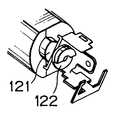
샤프트(112A)는 케이스(112)의 우측 끝부분에 형성되고, 나사를 통해 디스플레이부(3)에 고정된 베어링(bearing)(123) 회전을 위해 지지된다. 한편, 샤프트(121)는 나사를 통해 케이스(112)의 좌측 끝부분에 고정된다. 샤프트(121)는 나사를 통해 디스플레이부(3)에 고정된 수신 멤버(120)의 회전을 지지한다. 따라서, 케이스(118)와 집적되어 조립된 케이스(112)는 샤프트(112A) 및 샤프트(121)의 축 주위에서 디스플레이부(3)상의 회전 운동을 위해 설치된다. 캠(cam)(122)은 샤프트(121)에 연결되고(도 9c), 반전 스위치(87)를 ON 또는 OFF 상태로 교환시키도록 동작가능하다. 영상 픽업부(22)가 앞 또는 뒤로 전해지는가 여부는 반전 스위치(87)의 상태로부터 검출된다.The
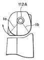
도 10은 도 9a에 도시된 선 I-I'에서 취해진 영상 픽업부(22)를 부분적으로 도시한다. 도 10에서 볼 수 있는 바와 같이, 샤프트(112A)(샤프트 121)는 케이스(112) 및 케이스(118)로부터 형성되는 실질적으로 원통형인 멤버의 중심에서 약간 상향 및 하향으로 떨어진 위치에 형성(배치)된다. 그래서, 실질적으로 원통형인 멤버는 케이스(118)가 샤프트(112A)로부터 최대 길이(1a)를 갖고 케이스(112)가 최소 길이(1b)를 갖도록 형성된다. 결과적으로, 영상 픽업부(22)는 외부 방향(도 10에서 시계 방향)으로 피봇팅할 수 있지만, 내부 방향(도 10에서 반시계 방향)으로 피봇팅할 수 없다.FIG. 10 partially shows the
도 11a는 영상 픽업부(22)의 영상 픽업 방향이 LCD(21)와 같은 방향으로 설정된 개인용 컴퓨터(1)를 도시하고, 도 11d는 도 11a의 선 I-I'을 따라 화살표로 나타내진 방향에서 관찰되는 영상 픽업부(22)를 확대하여 도시한다. 도 11b는 영상 픽업부(22)의 영상 픽업 방향이 LCD(21)에 대해 시계 방향으로 90도 만큼 회전된 개인용 컴퓨터(1)를 도시하고, 도 11e는 도 11a의 선 I-I'을 따라 화살표로 나 타내진 방향에서 관찰되는 도 11b의 영상 픽업부(22)를 확대하여 도시한다. 도 11c는 영상 픽업부(22)가 LCD(21)에 대해 시계 방향으로 180도 만큼 회전된 개인용 컴퓨터(1)를 도시하고, 도 11f는 도 11a의 선 I-I'을 따라 화살표로 나타내진 방향에서 관찰되는 도 11c의 영상 픽업부(22)를 확대하여 도시한다.FIG. 11A shows a
오목부(recess)(141)는 렌즈-배럴부(102)가 케이스(118)로부터 돌출되어 유지되는 동안 디스플레이부(3)가 본체(2)에 대해 피봇팅하여 닫힌 경우라도, 영상 픽업부(22)가 본체(2)와 간섭되지 않고 회전될 수 있도록 형성된다.The
도 12는 도 11a에서 선 I-I'을 따라 화살표로 나타내진 방향으로 관찰되는 마이크로폰(24)을 도시한다. 도 12를 참고로, 디스플레이부(3)는 마이크로폰(24) 앞의 정면벽(LCD(21)가 제공된)에 형성된 슬릿(slit)(151)을 갖고, 마이크로폰(24) 뒤의 후면벽(LCD(21)와 마주보는)에 형성된 또 다른 슬릿(152)을 갖는다. 결과적으로, 마이크로폰(24)은 LCD(21)의 정면에서 뿐만 아니라 LCD(21)의 후면에서도 사운드를 수집할 수 있다. 도 1, 도 2, 및 도 6에서, 도 12의 슬릿(151) 또는(152)에 대응하는 부분은 설명의 편의상 마이크로폰(24)으로 나타내짐을 주의하여야 한다.FIG. 12 shows the
도 13a 내지 도 13c는 다른 영상 픽업 방향으로 전해질 때 디스플레이부(3)의 후면에서부터 관찰되는 영상 픽업부(22)를 도시한다. 특히, 도 13a는 LCD(21)에 대해 반대 방향으로 전해질 때의 영상 픽업부(22)를 도시한다. 도 13b는 LCD(21)의 방향으로부터 90도 만큼 회전된 위치에 있을 때의 영상 픽업부(22)를 도시한다. 도 13c는 LCD(21)와 같은 방향으로 전해질 때의 영상 픽업부(22)를 도시 한다.13A to 13C show the
도 14a 내지 도 14c는 다른 영상 픽업 방향으로 전해질 때 디스플레이부(3)의 정면에서부터 관찰되는 영상 픽업부(22)를 도시한다. 특히, 도 14a는 LCD(21)에 대해 반대 방향으로 전해질 때의 영상 픽업부(22)를 도시한다. 도 14b는 LCD(21)의 방향으로부터 90도 만큼 회전된 위치에 있을 때의 영상 픽업부(22)를 도시한다. 도 14c는 LCD(21)와 같은 방향으로 전해질 때의 영상 픽업부(22)를 도시한다.14A to 14C show the
이후에는 상술된 구조를 갖는 개인용 컴퓨터(1)를 사용한 방법이 설명된다. 먼저, 디스플레이부(3)는 사용자가 LCD(21)를 볼 수 있도록 본체(2)로부터 실질적으로 상향 확장될 때까지 본체(2)에 대해 피봇팅하여 열린다. 도시되지 않은 물체의 영상을 개인용 컴퓨터(1)로 인출하기 위해, 사용자는 물체 쪽으로 영상 픽업 방향으로 CCD 비디오 카메라 유닛(101)을 회전시켜 적절한 위치에 정지시킨다. CCD 비디오 카메라 유닛(101)의 영상 픽업 방향은 LCD(21)와 같은 방향으로부터 반대 방향(LCD(21)의 후면 방향)으로 180도의 범위내에서 임의의 위치에 설정될 수 있으므로, CCD 비디오 카메라 유닛(101)은 LCD(21) 앞의 물체 영상, 즉 개인용 컴퓨터(1)의 사용자 뿐만 아니라 그 주위 물체의 영상도 픽업할 수 있다. CCD 비디오 카메라 유닛(101)이 영상 픽업 방향으로 설정된 이후에, 사용자는 CCD 비디오 카메라 유닛(101)이 물체에 초점을 맞추도록 렌즈-배럴부(102)의 위치를 조정하기 위해 조정 링(25)을 회전시킨다.Hereinafter, the method using the
CCD 비디오 카메라 유닛(101)이 성공적으로 물체에 초점을 맞추면, 사용자는 CCD 비디오 카메라(23)로 물체의 영상을 픽업하도록 셔터 버튼(10)을 누른다. 이와 같이 구해진 영상 데이터는 하드 디스크 드라이브(HDD)(56)에 저장된다. CCD 비디오 카메라(23)는 물체의 영상 데이터를 처리 블록(82)에 공급한다. 처리 블록(82)은 영상 데이터를 처리하고, 이어서 이들을 그래픽 칩(81)에 공급한다. 그래픽 칩(81)은 입력된 비디오 데이터를 내장된 VRAM(81A)에 저장하고, 이어서 이들을 판독하여 적절하게 LCD 제어기(83)로 출력한다. LCD 제어기(83)는 공급된 영상 데이터를 그래픽 칩(81)으로부터 LCD(21)에 출력하여, LCD(21)에 디스플레이한다. 또한, CCD 비디오 카메라에 의해 포착된 영상 데이터는 필요한 경우 도시되지 않은 프린터로 인쇄될 수 있다.When the CCD
또한, 개인용 컴퓨터(1)는 영상이 다른 통신군의 개인용 컴퓨터로 전송될 수 있도록 모뎀(50), 공중 전화선(90), 및 인터넷 서비스 제공자(91)를 통해 통신 네트워크(92)로 연결될 수 있다. 수신측에서는 영상이 수신된 영상 데이터를 근거로 실시간을 기초하여 디스플레이될 수 있다. 그러므로, 개인용 컴퓨터(1)는 텔레비젼 회의 시스템 등과 같은 시스템에서 사용될 수 있다.In addition, the
본 발명의 양호한 실시예는 특정한 항목을 사용해 설명되었지만, 이러한 설명은 단지 설명을 위한 것으로, 다음 청구항의 의도나 범위에서 벗어나지 않고 변화 및 변형이 이루어질 수 있는 것으로 이해되어야 한다.While the preferred embodiments of the present invention have been described using specific details, such description is for illustrative purposes only and it is to be understood that changes and modifications may be made without departing from the spirit or scope of the following claims.
본 발명에 따라 물체에 조정가능한 초점을 갖는 CCD(Charge Coupled Device) 비디오 카메라가 결합된 정보 처리 장치를 제공할 수 있다.According to the present invention, it is possible to provide an information processing apparatus incorporating a Charge Coupled Device (CCD) video camera having an adjustable focus on an object.
Claims (10)
Translated fromKoreanApplications Claiming Priority (2)
| Application Number | Priority Date | Filing Date | Title |
|---|---|---|---|
| JP10184359AJP2000020163A (en) | 1998-06-30 | 1998-06-30 | Information processor |
| JP98-184359 | 1998-06-30 |
Publications (2)
| Publication Number | Publication Date |
|---|---|
| KR20000006542A KR20000006542A (en) | 2000-01-25 |
| KR100685152B1true KR100685152B1 (en) | 2007-02-22 |
Family
ID=16151869
Family Applications (1)
| Application Number | Title | Priority Date | Filing Date |
|---|---|---|---|
| KR1019990025114AExpired - Fee RelatedKR100685152B1 (en) | 1998-06-30 | 1999-06-29 | Information processing device |
Country Status (6)
| Country | Link |
|---|---|
| US (1) | US6930725B1 (en) |
| EP (1) | EP0969352B1 (en) |
| JP (1) | JP2000020163A (en) |
| KR (1) | KR100685152B1 (en) |
| DE (1) | DE69927319T2 (en) |
| TW (1) | TW532491U (en) |
Families Citing this family (63)
| Publication number | Priority date | Publication date | Assignee | Title |
|---|---|---|---|---|
| KR20020001101A (en)* | 2000-06-26 | 2002-01-09 | 이형도 | Video camera for computer |
| US6481681B1 (en)* | 2000-08-30 | 2002-11-19 | 3Com Corporation | Clip apparatus for a laptop computer |
| US7102615B2 (en) | 2002-07-27 | 2006-09-05 | Sony Computer Entertainment Inc. | Man-machine interface using a deformable device |
| US8797260B2 (en) | 2002-07-27 | 2014-08-05 | Sony Computer Entertainment Inc. | Inertially trackable hand-held controller |
| US7883415B2 (en) | 2003-09-15 | 2011-02-08 | Sony Computer Entertainment Inc. | Method and apparatus for adjusting a view of a scene being displayed according to tracked head motion |
| US9393487B2 (en) | 2002-07-27 | 2016-07-19 | Sony Interactive Entertainment Inc. | Method for mapping movements of a hand-held controller to game commands |
| US8570378B2 (en) | 2002-07-27 | 2013-10-29 | Sony Computer Entertainment Inc. | Method and apparatus for tracking three-dimensional movements of an object using a depth sensing camera |
| US9474968B2 (en) | 2002-07-27 | 2016-10-25 | Sony Interactive Entertainment America Llc | Method and system for applying gearing effects to visual tracking |
| US8686939B2 (en) | 2002-07-27 | 2014-04-01 | Sony Computer Entertainment Inc. | System, method, and apparatus for three-dimensional input control |
| US8313380B2 (en) | 2002-07-27 | 2012-11-20 | Sony Computer Entertainment America Llc | Scheme for translating movements of a hand-held controller into inputs for a system |
| US7760248B2 (en) | 2002-07-27 | 2010-07-20 | Sony Computer Entertainment Inc. | Selective sound source listening in conjunction with computer interactive processing |
| US7391409B2 (en)* | 2002-07-27 | 2008-06-24 | Sony Computer Entertainment America Inc. | Method and system for applying gearing effects to multi-channel mixed input |
| US9682319B2 (en) | 2002-07-31 | 2017-06-20 | Sony Interactive Entertainment Inc. | Combiner method for altering game gearing |
| US8072470B2 (en) | 2003-05-29 | 2011-12-06 | Sony Computer Entertainment Inc. | System and method for providing a real-time three-dimensional interactive environment |
| US9573056B2 (en) | 2005-10-26 | 2017-02-21 | Sony Interactive Entertainment Inc. | Expandable control device via hardware attachment |
| US8287373B2 (en) | 2008-12-05 | 2012-10-16 | Sony Computer Entertainment Inc. | Control device for communicating visual information |
| US8323106B2 (en) | 2008-05-30 | 2012-12-04 | Sony Computer Entertainment America Llc | Determination of controller three-dimensional location using image analysis and ultrasonic communication |
| US10279254B2 (en) | 2005-10-26 | 2019-05-07 | Sony Interactive Entertainment Inc. | Controller having visually trackable object for interfacing with a gaming system |
| US7874917B2 (en) | 2003-09-15 | 2011-01-25 | Sony Computer Entertainment Inc. | Methods and systems for enabling depth and direction detection when interfacing with a computer program |
| US7605862B2 (en)* | 2004-01-20 | 2009-10-20 | Chuan-Kung Hou | Apparatus for a portable electronic device |
| CN1332230C (en)* | 2004-03-03 | 2007-08-15 | 纬创资通股份有限公司 | Electronic device |
| KR101070631B1 (en)* | 2004-06-09 | 2011-10-07 | 삼성전자주식회사 | portable computer with camera module |
| CN100338551C (en)* | 2004-06-18 | 2007-09-19 | 华硕电脑股份有限公司 | Electronic device with image capturing unit |
| US8547401B2 (en)* | 2004-08-19 | 2013-10-01 | Sony Computer Entertainment Inc. | Portable augmented reality device and method |
| US7486279B2 (en)* | 2004-11-30 | 2009-02-03 | Intel Corporation | Integrated input and display device for a mobile computer |
| TWI250790B (en) | 2005-01-07 | 2006-03-01 | Asustek Comp Inc | Display device having rotational image-capturing module |
| CN100454211C (en)* | 2005-01-21 | 2009-01-21 | 华硕电脑股份有限公司 | Display with rotatable image acquisition assembly |
| CN100339792C (en)* | 2005-01-21 | 2007-09-26 | 北京华旗资讯数码科技有限公司 | Computer case |
| JP2007065932A (en)* | 2005-08-30 | 2007-03-15 | Fujitsu Ltd | Information processing apparatus and information processing apparatus control method |
| TWM291671U (en)* | 2005-11-09 | 2006-06-01 | Wistron Corp | Enclosure with rotary functions and electric device for combining the enclosure |
| US20080013262A1 (en)* | 2006-06-30 | 2008-01-17 | Logitech Europe S.A. | Computer monitor with detachable module |
| US8781151B2 (en) | 2006-09-28 | 2014-07-15 | Sony Computer Entertainment Inc. | Object detection using video input combined with tilt angle information |
| US8310656B2 (en) | 2006-09-28 | 2012-11-13 | Sony Computer Entertainment America Llc | Mapping movements of a hand-held controller to the two-dimensional image plane of a display screen |
| USRE48417E1 (en) | 2006-09-28 | 2021-02-02 | Sony Interactive Entertainment Inc. | Object direction using video input combined with tilt angle information |
| US8542907B2 (en) | 2007-12-17 | 2013-09-24 | Sony Computer Entertainment America Llc | Dynamic three-dimensional object mapping for user-defined control device |
| US8432485B1 (en) | 2007-12-19 | 2013-04-30 | Logitech Europe S.A. | Optimized designs for embedding webcam modules with superior image quality in electronics displays |
| CN102016877B (en) | 2008-02-27 | 2014-12-10 | 索尼计算机娱乐美国有限责任公司 | Method for capturing depth data of a scene and applying computer actions |
| US8368753B2 (en) | 2008-03-17 | 2013-02-05 | Sony Computer Entertainment America Llc | Controller with an integrated depth camera |
| US8961313B2 (en) | 2009-05-29 | 2015-02-24 | Sony Computer Entertainment America Llc | Multi-positional three-dimensional controller |
| USD673201S1 (en)* | 2009-01-05 | 2012-12-25 | Sony Corporation | Video camera |
| US20100182486A1 (en)* | 2009-01-19 | 2010-07-22 | Backer Chou | Portable Image Acquisitioner with Micro Objective Lens |
| US8527657B2 (en) | 2009-03-20 | 2013-09-03 | Sony Computer Entertainment America Llc | Methods and systems for dynamically adjusting update rates in multi-player network gaming |
| US8342963B2 (en) | 2009-04-10 | 2013-01-01 | Sony Computer Entertainment America Inc. | Methods and systems for enabling control of artificial intelligence game characters |
| US8393964B2 (en) | 2009-05-08 | 2013-03-12 | Sony Computer Entertainment America Llc | Base station for position location |
| US8142288B2 (en) | 2009-05-08 | 2012-03-27 | Sony Computer Entertainment America Llc | Base station movement detection and compensation |
| CN101997940B (en)* | 2009-08-19 | 2014-07-16 | 鸿富锦精密工业(深圳)有限公司 | Portable electronic device |
| US8508919B2 (en)* | 2009-09-14 | 2013-08-13 | Microsoft Corporation | Separation of electrical and optical components |
| KR101010384B1 (en)* | 2010-04-07 | 2011-01-21 | (주) 아이티서포트 | Portable Video Recorder for Consultation and Investigation |
| US20150082355A1 (en)* | 2010-04-11 | 2015-03-19 | Mark Tiddens | Method and Apparatus for Interfacing Broadcast Television and Video Displayed Media with Networked Components |
| KR101844830B1 (en) | 2011-02-07 | 2018-04-04 | 삼성디스플레이 주식회사 | Display device |
| USD706850S1 (en)* | 2012-12-20 | 2014-06-10 | Panasonic Corporation | Camera for television apparatus |
| USD744021S1 (en)* | 2013-12-19 | 2015-11-24 | Panasonic Intellectual Property Management Co., Ltd. | Camera for television apparatus |
| WO2016122557A1 (en) | 2015-01-30 | 2016-08-04 | Hewlett-Packard Development Company, L.P. | Webcam shutter |
| CN105827757A (en)* | 2016-04-12 | 2016-08-03 | 乐视控股(北京)有限公司 | Roller type mobile phone camera shooting system and method |
| CN106764271B (en)* | 2016-11-18 | 2018-11-06 | 明基智能科技(上海)有限公司 | Display device |
| US20180234596A1 (en)* | 2017-02-13 | 2018-08-16 | Asia Vital Components Co., Ltd. | Camera module protection structure |
| CN207196002U (en)* | 2017-09-25 | 2018-04-06 | 深圳市商汤科技有限公司 | Authenticating device |
| CN108087681B (en)* | 2017-12-12 | 2019-11-05 | 深圳创维-Rgb电子有限公司 | A kind of pick-up head mounting structure and display equipment |
| TWI701495B (en)* | 2018-02-28 | 2020-08-11 | 仁寶電腦工業股份有限公司 | Camera module and electronic device |
| JP6797884B2 (en)* | 2018-12-04 | 2020-12-09 | Necパーソナルコンピュータ株式会社 | Electronics |
| US10942421B2 (en)* | 2018-12-19 | 2021-03-09 | Nidec Copal Corporation | Blade driving device and electronic device |
| CN114324194B (en)* | 2022-01-24 | 2023-10-24 | 河北北方学院 | Grape gray mold monitoring device |
| USD1082894S1 (en)* | 2025-01-21 | 2025-07-08 | Lianghuai Feng | Rotating camera |
Citations (4)
| Publication number | Priority date | Publication date | Assignee | Title |
|---|---|---|---|---|
| EP0683596A2 (en)* | 1994-05-18 | 1995-11-22 | Sharp Kabushiki Kaisha | Card type camera with image processing function |
| JPH07312716A (en)* | 1994-05-18 | 1995-11-28 | Sharp Corp | Card camera |
| US5537175A (en)* | 1993-09-09 | 1996-07-16 | Sony Corporation | Camera adaption for self photography |
| JPH10164414A (en)* | 1996-12-03 | 1998-06-19 | Canon Inc | Notebook personal computer with built-in camera |
Family Cites Families (12)
| Publication number | Priority date | Publication date | Assignee | Title |
|---|---|---|---|---|
| JPH075188B2 (en)* | 1988-05-02 | 1995-01-25 | 株式会社長崎機器製作所 | Dispenser for conveyor |
| JP3255995B2 (en)* | 1992-10-23 | 2002-02-12 | 株式会社日立製作所 | Videophone equipment |
| US5612732A (en)* | 1993-03-31 | 1997-03-18 | Casio Computer Co., Ltd. | Portable compact imaging and displaying apparatus with rotatable camera |
| USD363471S (en)* | 1993-11-12 | 1995-10-24 | International Business Machines Corporation | Multi-media portable computer |
| JP3183056B2 (en)* | 1994-08-26 | 2001-07-03 | 株式会社日立製作所 | Imaging device |
| US6292272B1 (en) | 1995-08-03 | 2001-09-18 | Canon Kabushiki Kaisha | Image sensor |
| US6141052A (en)* | 1996-04-15 | 2000-10-31 | Sony Corporation | Portable personal computer and electronic camera |
| US5768163A (en)* | 1996-04-15 | 1998-06-16 | Hewlett-Packard | Versatile attachment of handheld devices to a host computing system |
| JP4001958B2 (en)* | 1996-08-19 | 2007-10-31 | ソニー株式会社 | Imaging device |
| US5801919A (en)* | 1997-04-04 | 1998-09-01 | Gateway 2000, Inc. | Adjustably mounted camera assembly for portable computers |
| US5880928A (en)* | 1997-06-13 | 1999-03-09 | Ma; His-Kuang | Notebook computer with audio and video effects |
| TW352206U (en)* | 1997-12-30 | 1999-02-01 | First Int Computer Inc | Structure for hidden type image picking apparatus of notebook computer |
- 1998
- 1998-06-30JPJP10184359Apatent/JP2000020163A/ennot_activeWithdrawn
- 1999
- 1999-06-25TWTW091214472Upatent/TW532491U/ennot_activeIP Right Cessation
- 1999-06-28USUS09/340,764patent/US6930725B1/ennot_activeExpired - Fee Related
- 1999-06-29EPEP99305091Apatent/EP0969352B1/ennot_activeExpired - Lifetime
- 1999-06-29DEDE69927319Tpatent/DE69927319T2/ennot_activeExpired - Fee Related
- 1999-06-29KRKR1019990025114Apatent/KR100685152B1/ennot_activeExpired - Fee Related
Patent Citations (4)
| Publication number | Priority date | Publication date | Assignee | Title |
|---|---|---|---|---|
| US5537175A (en)* | 1993-09-09 | 1996-07-16 | Sony Corporation | Camera adaption for self photography |
| EP0683596A2 (en)* | 1994-05-18 | 1995-11-22 | Sharp Kabushiki Kaisha | Card type camera with image processing function |
| JPH07312716A (en)* | 1994-05-18 | 1995-11-28 | Sharp Corp | Card camera |
| JPH10164414A (en)* | 1996-12-03 | 1998-06-19 | Canon Inc | Notebook personal computer with built-in camera |
Also Published As
| Publication number | Publication date |
|---|---|
| JP2000020163A (en) | 2000-01-21 |
| EP0969352B1 (en) | 2005-09-21 |
| US6930725B1 (en) | 2005-08-16 |
| DE69927319T2 (en) | 2006-06-29 |
| TW532491U (en) | 2003-05-11 |
| EP0969352A2 (en) | 2000-01-05 |
| KR20000006542A (en) | 2000-01-25 |
| DE69927319D1 (en) | 2006-02-02 |
| EP0969352A3 (en) | 2000-12-06 |
Similar Documents
| Publication | Publication Date | Title |
|---|---|---|
| KR100685152B1 (en) | Information processing device | |
| EP0969353B1 (en) | Information processing apparatus | |
| US6842652B2 (en) | Image capture device | |
| CN100356293C (en) | Portable computer with camera | |
| US6657654B2 (en) | Camera for use with personal digital assistants with high speed communication link | |
| US7164432B1 (en) | Information processing apparatus and method therefor, and medium | |
| JP4366746B2 (en) | Information processing apparatus and method, and recording medium | |
| JP2001298654A (en) | Information processor | |
| EP0969351A2 (en) | Information processing apparatus | |
| KR20000006574A (en) | Information processing apparatus, information processing method and storage medium | |
| JP2004304458A (en) | Foldable portable terminal device | |
| JP3263757B2 (en) | Information processing device | |
| JP3847158B2 (en) | Mobile phone equipment | |
| JP2001245185A (en) | Information processing apparatus | |
| JP2001084060A (en) | Information processor | |
| JP2000020221A (en) | Information processor | |
| JPH11212893A (en) | Program starting device/method in electronic unit, medium and electronic unit | |
| JP2000023021A (en) | Information processor, method and providing medium | |
| JP2000020162A (en) | Information processor | |
| JP2000020473A (en) | Portable information processor | |
| JP2001216049A (en) | Small electronic equipment | |
| JP2000020161A (en) | Information processor | |
| CN2794112Y (en) | Rotating mechanism of built-in camera of cell phone | |
| JP3395776B2 (en) | Information processing device | |
| JP2000105687A (en) | Device and method for starting program in electronic equipment, and medium |
Legal Events
| Date | Code | Title | Description |
|---|---|---|---|
| PA0109 | Patent application | St.27 status event code:A-0-1-A10-A12-nap-PA0109 | |
| AMND | Amendment | ||
| P11-X000 | Amendment of application requested | St.27 status event code:A-2-2-P10-P11-nap-X000 | |
| P13-X000 | Application amended | St.27 status event code:A-2-2-P10-P13-nap-X000 | |
| PG1501 | Laying open of application | St.27 status event code:A-1-1-Q10-Q12-nap-PG1501 | |
| A201 | Request for examination | ||
| AMND | Amendment | ||
| P11-X000 | Amendment of application requested | St.27 status event code:A-2-2-P10-P11-nap-X000 | |
| P13-X000 | Application amended | St.27 status event code:A-2-2-P10-P13-nap-X000 | |
| PA0201 | Request for examination | St.27 status event code:A-1-2-D10-D11-exm-PA0201 | |
| R17-X000 | Change to representative recorded | St.27 status event code:A-3-3-R10-R17-oth-X000 | |
| D13-X000 | Search requested | St.27 status event code:A-1-2-D10-D13-srh-X000 | |
| D14-X000 | Search report completed | St.27 status event code:A-1-2-D10-D14-srh-X000 | |
| E902 | Notification of reason for refusal | ||
| PE0902 | Notice of grounds for rejection | St.27 status event code:A-1-2-D10-D21-exm-PE0902 | |
| T11-X000 | Administrative time limit extension requested | St.27 status event code:U-3-3-T10-T11-oth-X000 | |
| T11-X000 | Administrative time limit extension requested | St.27 status event code:U-3-3-T10-T11-oth-X000 | |
| AMND | Amendment | ||
| P11-X000 | Amendment of application requested | St.27 status event code:A-2-2-P10-P11-nap-X000 | |
| P13-X000 | Application amended | St.27 status event code:A-2-2-P10-P13-nap-X000 | |
| E601 | Decision to refuse application | ||
| PE0601 | Decision on rejection of patent | St.27 status event code:N-2-6-B10-B15-exm-PE0601 | |
| J201 | Request for trial against refusal decision | ||
| PJ0201 | Trial against decision of rejection | St.27 status event code:A-3-3-V10-V11-apl-PJ0201 | |
| R17-X000 | Change to representative recorded | St.27 status event code:A-3-3-R10-R17-oth-X000 | |
| AMND | Amendment | ||
| E13-X000 | Pre-grant limitation requested | St.27 status event code:A-2-3-E10-E13-lim-X000 | |
| P11-X000 | Amendment of application requested | St.27 status event code:A-2-2-P10-P11-nap-X000 | |
| P13-X000 | Application amended | St.27 status event code:A-2-2-P10-P13-nap-X000 | |
| PB0901 | Examination by re-examination before a trial | St.27 status event code:A-6-3-E10-E12-rex-PB0901 | |
| B701 | Decision to grant | ||
| PB0701 | Decision of registration after re-examination before a trial | St.27 status event code:A-3-4-F10-F13-rex-PB0701 | |
| GRNT | Written decision to grant | ||
| PR0701 | Registration of establishment | St.27 status event code:A-2-4-F10-F11-exm-PR0701 | |
| PR1002 | Payment of registration fee | St.27 status event code:A-2-2-U10-U11-oth-PR1002 Fee payment year number:1 | |
| PG1601 | Publication of registration | St.27 status event code:A-4-4-Q10-Q13-nap-PG1601 | |
| R18-X000 | Changes to party contact information recorded | St.27 status event code:A-5-5-R10-R18-oth-X000 | |
| PN2301 | Change of applicant | St.27 status event code:A-5-5-R10-R13-asn-PN2301 St.27 status event code:A-5-5-R10-R11-asn-PN2301 | |
| LAPS | Lapse due to unpaid annual fee | ||
| PC1903 | Unpaid annual fee | St.27 status event code:A-4-4-U10-U13-oth-PC1903 Not in force date:20100215 Payment event data comment text:Termination Category : DEFAULT_OF_REGISTRATION_FEE | |
| PC1903 | Unpaid annual fee | St.27 status event code:N-4-6-H10-H13-oth-PC1903 Ip right cessation event data comment text:Termination Category : DEFAULT_OF_REGISTRATION_FEE Not in force date:20100215 | |
| PN2301 | Change of applicant | St.27 status event code:A-5-5-R10-R13-asn-PN2301 St.27 status event code:A-5-5-R10-R11-asn-PN2301 |