KR100684904B1 - Semiconductor memory device including on die termination circuit and its on die termination method - Google Patents
Semiconductor memory device including on die termination circuit and its on die termination methodDownload PDFInfo
- Publication number
- KR100684904B1 KR100684904B1KR1020050071750AKR20050071750AKR100684904B1KR 100684904 B1KR100684904 B1KR 100684904B1KR 1020050071750 AKR1020050071750 AKR 1020050071750AKR 20050071750 AKR20050071750 AKR 20050071750AKR 100684904 B1KR100684904 B1KR 100684904B1
- Authority
- KR
- South Korea
- Prior art keywords
- pull
- resistance value
- resistor
- termination
- signal
- Prior art date
- Legal status (The legal status is an assumption and is not a legal conclusion. Google has not performed a legal analysis and makes no representation as to the accuracy of the status listed.)
- Expired - Fee Related
Links
Images


Classifications
- G—PHYSICS
- G11—INFORMATION STORAGE
- G11C—STATIC STORES
- G11C7/00—Arrangements for writing information into, or reading information out from, a digital store
- G11C7/10—Input/output [I/O] data interface arrangements, e.g. I/O data control circuits, I/O data buffers
- G11C7/1048—Data bus control circuits, e.g. precharging, presetting, equalising
- G—PHYSICS
- G11—INFORMATION STORAGE
- G11C—STATIC STORES
- G11C7/00—Arrangements for writing information into, or reading information out from, a digital store
- G11C7/10—Input/output [I/O] data interface arrangements, e.g. I/O data control circuits, I/O data buffers
- G11C7/1078—Data input circuits, e.g. write amplifiers, data input buffers, data input registers, data input level conversion circuits
- G—PHYSICS
- G11—INFORMATION STORAGE
- G11C—STATIC STORES
- G11C5/00—Details of stores covered by group G11C11/00
- G11C5/06—Arrangements for interconnecting storage elements electrically, e.g. by wiring
- G11C5/063—Voltage and signal distribution in integrated semi-conductor memory access lines, e.g. word-line, bit-line, cross-over resistance, propagation delay
- G—PHYSICS
- G11—INFORMATION STORAGE
- G11C—STATIC STORES
- G11C7/00—Arrangements for writing information into, or reading information out from, a digital store
- G11C7/10—Input/output [I/O] data interface arrangements, e.g. I/O data control circuits, I/O data buffers
- G11C7/1051—Data output circuits, e.g. read-out amplifiers, data output buffers, data output registers, data output level conversion circuits
- G11C7/1057—Data output buffers, e.g. comprising level conversion circuits, circuits for adapting load
- G—PHYSICS
- G11—INFORMATION STORAGE
- G11C—STATIC STORES
- G11C7/00—Arrangements for writing information into, or reading information out from, a digital store
- G11C7/10—Input/output [I/O] data interface arrangements, e.g. I/O data control circuits, I/O data buffers
- G11C7/1078—Data input circuits, e.g. write amplifiers, data input buffers, data input registers, data input level conversion circuits
- G11C7/1084—Data input buffers, e.g. comprising level conversion circuits, circuits for adapting load
- G—PHYSICS
- G11—INFORMATION STORAGE
- G11C—STATIC STORES
- G11C7/00—Arrangements for writing information into, or reading information out from, a digital store
- G11C7/22—Read-write [R-W] timing or clocking circuits; Read-write [R-W] control signal generators or management
- G—PHYSICS
- G11—INFORMATION STORAGE
- G11C—STATIC STORES
- G11C2207/00—Indexing scheme relating to arrangements for writing information into, or reading information out from, a digital store
- G11C2207/10—Aspects relating to interfaces of memory device to external buses
- G11C2207/105—Aspects related to pads, pins or terminals
Landscapes
- Dram (AREA)
Abstract
Translated fromKoreanDescription
Translated fromKorean도 1은 본 발명의 실시예에 따른 반도체 메모리 장치를 보여주는 블록도이다.1 is a block diagram illustrating a semiconductor memory device according to an embodiment of the present invention.
도 2는 도 1에 도시된 온 다이 종단 회로를 예로서 보여주는 회로도이다.FIG. 2 is a circuit diagram illustrating the on die termination circuit shown in FIG. 1 as an example.
도 3은 데이터(DQ0)의 레벨이 규칙적으로 변하는 경우에 풀업 제어신호(CU0) 및 풀다운 제어신호(CD0)의 파형을 보여주기 위한 타이밍도이다.3 is a timing diagram for showing waveforms of the pull-up control signal CU0 and the pull-down control signal CD0 when the level of the data DQ0 changes regularly.
도 4는 클록신호(CLK)의 일정 주기 동안, 데이터(DQ0)가 로우 레벨을 유지하는 경우에 풀업 제어신호(CU0) 및 풀다운 제어신호(CD0)의 파형을 보여주기 위한 타이밍도이다.FIG. 4 is a timing diagram showing waveforms of the pull-up control signal CU0 and the pull-down control signal CD0 when the data DQ0 maintains a low level for a certain period of the clock signal CLK.
도 5는 클록신호(CLK)의 일정 주기 동안, 데이터(DQ0)가 하이 레벨을 유지하는 경우에 풀업 제어신호(CU0) 및 풀다운 제어신호(CD0)의 파형을 보여주기 위한 타이밍도이다.FIG. 5 is a timing diagram illustrating waveforms of the pull-up control signal CU0 and the pull-down control signal CD0 when the data DQ0 maintains a high level for a certain period of the clock signal CLK.
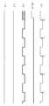
도 6은 데이터 윈도우 다이어그램을 보여주는 그래프이다.6 is a graph showing a data window diagram.
*도면의 주요부분에 대한 부호의 설명** Explanation of symbols for main parts of drawings *
100: 반도체 메모리 장치 110: 온 다이 종단 회로100: semiconductor memory device 110: on die termination circuit
120: 내부회로 130: 모드 레지스터120: internal circuit 130: mode register
210: 풀업 저항부 220: 풀다운 저항부210: pull-up resistor 220: pull-down resistor
230: 풀업 저항 제어부 240: 풀다운 저항 제어부230: pull-up resistor control unit 240: pull-down resistor control unit
250: 스위치부250: switch unit
본 발명은 반도체 메모리 장치에 관한 것으로, 더욱 상세하게는 온 다이 종단 회로를 포함하는 반도체 메모리 장치 및 그것의 온 다이 종단 방법에 관한 것이다.The present invention relates to a semiconductor memory device, and more particularly, to a semiconductor memory device including an on die termination circuit and an on die termination method thereof.
반도체 메모리 장치(semiconductor memory device)는 데이터를 저장해 두고 필요할 때 꺼내어 읽어볼 수 있는 기억장치이다. 반도체 메모리 장치는 크게 램(Random Access Memory; RAM)과 롬(Read Only Memory; ROM)으로 나눌 수 있다. 램(RAM)은 전원이 끊어지면 저장된 데이터가 소멸하는 휘발성 메모리 장치(volatile memory device)이다. 롬(ROM)은 전원이 끊어지더라도 저장된 데이터가 소멸하지 않는 불휘발성 메모리(nonvolatile memory device)이다. 램(RAM)은 DRAM(Dynamic RAM), SRAM(Static RAM) 등을 포함한다. 롬(ROM)은 PROM(Programmable ROM), EPROM(Erasable PROM), EEPROM(Electrically EPROM), 플래시 메모리 장치(flash memory device) 등을 포함한다.A semiconductor memory device is a memory device that stores data and can be read out when needed. The semiconductor memory device may be largely divided into a random access memory (RAM) and a read only memory (ROM). RAM is a volatile memory device in which stored data is lost when power is lost. ROM is a nonvolatile memory device in which stored data is not destroyed even when a power supply is cut off. RAM includes Dynamic RAM (DRAM), Static RAM (SRAM), and the like. The ROM includes a programmable ROM (PROM), an erasable PROM (EPROM), an electrically EPROM (EEPROM), a flash memory device, and the like.
반도체 메모리 장치는 패드를 통해 외부에서 신호를 입력받는다. 반도체 메 모리 장치는 일반적으로 임피던스 정합(impedance matching)을 위해 데이터 라인을 종단하는 온 다이 종단 회로(On Die Termination circuit; ODT 회로)를 포함한다. 온 다이 종단 회로는 종단 저항 소자를 사용하여 신호의 반사를 억제함으로써 입력 신호의 충실도(signal integrity)를 높인다.The semiconductor memory device receives a signal from the outside through a pad. Semiconductor memory devices typically include an on die termination circuit (ODT circuit) that terminates a data line for impedance matching. On-die termination circuits use termination resistors to suppress signal reflection to increase the signal integrity of the input signal.
종래의 온 다이 종단 회로는 입력되는 데이터의 위상 변화에 관계없이 일정한 종단 저항값을 갖는다. 온 다이 종단 회로의 종단 저항값은 초기 동작 시에 모드 레지스터(MRS)에 저장된 값에 의해 결정된다. 그러나 종래의 온 다이 종단 회로는 항상 일정한 종단 저항값을 갖기 때문에 데이터의 다양한 위상 변화에 따른 동작 작음(Inter Symbol Interference; ISI)에 효과적으로 대응할 수 없다.Conventional on die termination circuits have a constant termination resistance value regardless of the phase change of the data being input. The termination resistance of the on die termination circuit is determined by the value stored in the mode register (MRS) during initial operation. However, the conventional on-die termination circuit always has a constant termination resistance value, and thus cannot effectively cope with Inter Symbol Interference (ISI) due to various phase changes of data.
예를 들어, 데이터의 위상이 "로우(L)-하이(H)-로우(L)-하이(H)"인 제 1 경우(first case)와 "로우(L)-로우(L)-로우(L)-하이(H)"인 제 2 경우(second case)를 가정하자. 제 1 및 제 2 경우의 종단 저항값은 동일하지만, 동작 잡음(ISI)의 영향은 다르다. 제 1 및 제 2 경우는 동작 작음(ISI)의 영향을 달리하므로 서로 다른 신호 전달 특성을 갖는다. 이는 유효한 입력 신호의 윈도우 특성을 감쇄하는 결과를 초래한다.For example, the first case where the phase of the data is "Low-High (H) -Low (L) -High (H)" and "Low-L (L) -Low" Assume a second case of (L) -high (H) ". The termination resistance values in the first and second cases are the same, but the influence of the operating noise ISI is different. The first and second cases have different signal propagation characteristics because they have different influences of operation smallness (ISI). This results in attenuation of the window characteristics of the valid input signal.
즉, 종래의 반도체 메모리 장치는 초기 동작 시에 모드 레지스터에 저장된 값에 의해 온 다이 종단 회로의 종단 저항값을 획일적으로 결정한다. 따라서 종래의 반도체 메모리 장치는 동작 잡음(ISI)의 영향에 대해 대체할 수 없는 문제점을 가지고 있다.That is, the conventional semiconductor memory device uniformly determines the termination resistance value of the on die termination circuit by the value stored in the mode register during the initial operation. Therefore, the conventional semiconductor memory device has a problem that cannot be replaced with the influence of the operating noise (ISI).
본 발명은 상술한 문제점을 해결하기 위하여 제안된 것으로, 본 발명의 목적은 입력 신호의 위상 변화에 따라 종단 저항값을 가변하여 동작 잡음에 영향을 줄인 온 다이 종단 회로를 포함한 반도체 메모리 장치 및 온 다이 종단 방법을 제공하는 데 있다.SUMMARY OF THE INVENTION The present invention has been proposed to solve the above-described problems, and an object of the present invention is to provide a semiconductor memory device and an on-die including an on-die termination circuit having a variable termination resistance according to a phase change of an input signal to reduce operating noise To provide a termination method.
본 발명에 따른 반도체 메모리 장치는, 패드를 통해 입력되는 신호의 위상 변화를 감지하여 종단 저항값을 조절하는 온 다이 종단 회로를 포함한다. 상기 온 다이 종단 회로는 클록 신호의 n(n은 자연수) 주기 동안 동일한 위상의 신호가 지속적으로 입력되는 경우에 상기 종단 저항값을 가변한다.The semiconductor memory device according to the present invention includes an on-die termination circuit which senses a phase change of a signal input through a pad and adjusts a termination resistance value. The on die termination circuit varies the termination resistance value when a signal of the same phase is continuously input during n (n is a natural number) period of a clock signal.
실시예로서, 상기 온 다이 종단 회로는, 풀업 종단 저항값을 갖는 풀업 저항부; 및 풀다운 종단 저항값을 갖는 풀다운 저항부를 포함하되, 상기 풀업 종단 저항값과 상기 풀다운 종단 저항값은 독립적으로 조절된다. 상기 온 다이 종단 회로는, 상기 신호의 위상 변화를 감지하여 상기 풀업 종단 저항값을 조절하는 풀업 저항 제어부; 및 상기 신호의 위상 변화를 감지하여 상기 풀다운 종단 저항값을 조절하는 풀다운 저항 제어부를 더 포함한다. 상기 온 다이 종단 회로는 모드 레지스터에서 제공되는 제어신호(ODT_ON)에 응답하여 상기 온 다이 종단 회로를 온(on) 또는 오프(off) 하는 스위치부를 더 포함한다.In an embodiment, the on die termination circuit may include a pull-up resistor having a pull-up termination resistance; And a pull-down resistor having a pull-down termination resistance, wherein the pull-up termination resistance and the pull-down termination resistance are independently adjusted. The on die termination circuit may include: a pull-up resistor controller configured to sense a phase change of the signal and adjust the pull-up termination resistance value; And a pull-down resistor controller configured to adjust the pull-down termination resistance value by sensing a phase change of the signal. The on die termination circuit further includes a switch unit to turn on or off the on die termination circuit in response to a control signal ODT_ON provided from a mode register.
여기에서, 상기 풀업 저항 제어부는 클록 신호의 n(n은 자연수) 주기 동안 동일한 위상의 신호가 입력되는 경우에 상기 풀업 종단 저항값을 가변한다. 상기 풀업 저항 제어부는 상기 클록 신호의 n(n은 자연수) 주기 동안 로우 레벨의 신호 가 입력되는 경우에 상기 풀업 종단 저항값을 줄인다. 상기 풀다운 저항 제어부는 클록 신호의 n(n은 자연수) 주기 동안 동일한 위상의 신호가 입력되는 경우에 상기 풀다운 종단 저항값을 가변한다. 상기 풀다운 저항 제어부는 상기 클록 신호의 n(n은 자연수) 주기 동안 하이 레벨의 신호가 입력되는 경우에 상기 풀다운 종단 저항값을 줄인다.Here, the pull-up resistor controller varies the pull-up termination resistance value when a signal having the same phase is input during n (n is a natural number) period of a clock signal. The pull-up resistor controller reduces the pull-up termination resistance value when a low level signal is input during n (n is a natural number) period of the clock signal. The pull-down resistor controller varies the pull-down termination resistance value when a signal having the same phase is input during n (n is a natural number) period of a clock signal. The pull-down resistor control unit reduces the pull-down termination resistance value when a high level signal is input during n (n is a natural number) period of the clock signal.
본 발명에 따른 반도체 메모리 장치의 다른 일면은, 복수의 패드를 통해 입력되는 신호의 위상 변화를 각각 독립적으로 감지하여 종단 저항값을 독립적으로 조절하는 복수의 온 다이 종단 회로를 포함한다.Another aspect of the semiconductor memory device according to the present invention includes a plurality of on-die termination circuits that independently sense phase changes of signals input through a plurality of pads and independently adjust termination resistance values.
실시예로서, 각각의 온 다이 종단 회로는, 풀업 종단 저항값을 갖는 풀업 저항부; 및 풀다운 종단 저항값을 갖는 풀다운 저항부를 포함하되, 풀업 종단 저항값과 상기 풀다운 종단 저항값은 독립적으로 조절된다.As an embodiment, each on die termination circuit may include a pull-up resistor having a pull-up termination resistance value; And a pull-down resistor having a pull-down termination resistor, wherein the pull-up resistor and the pull-down resistor are independently adjusted.
실시예로서, 각각의 온 다이 종단 회로는, 풀업 종단 저항값을 갖는 풀업 저항부; 풀다운 종단 저항값을 갖는 풀다운 저항부; 상기 풀업 저항부와 상기 풀다운 저항부 사이에 연결되며, 모드 레지스터에서 제공되는 제어신호(ODT_ON)에 응답하여 상기 복수의 온 다이 종단 회로를 온(on) 또는 오프(off) 하는 스위치부; 데이터의 위상 변화를 감지하여 상기 풀업 종단 저항값을 조절하는 풀업 저항 제어부; 및 상기 데이터의 위상 변화를 감지하여 상기 풀다운 종단 저항값을 조절하는 풀다운 저항 제어부를 포함한다. 상기 풀업 저항 제어부는 클록 신호의 n(n은 자연수) 주기 동안 로우 레벨의 데이터가 입력되는 경우에 상기 풀업 종단 저항값을 가변한다. 상기 풀다운 저항 제어부는 클록 신호의 n(n은 자연수) 주기 동안 하이 레벨의 데이터가 입력되는 경우에 상기 풀다운 종단 저항값을 가변한다.As an embodiment, each on die termination circuit may include a pull-up resistor having a pull-up termination resistance value; A pull-down resistor having a pull-down termination resistance value; A switch unit connected between the pull-up resistor unit and the pull-down resistor unit and turning on or off the plurality of on die termination circuits in response to a control signal (ODT_ON) provided from a mode register; A pull-up resistor controller configured to adjust a pull-up termination resistance value by sensing a phase change of data; And a pull-down resistor controller configured to adjust the pull-down termination resistance value by sensing a phase change of the data. The pull-up resistor controller varies the pull-up termination resistance value when low-level data is input during n (n is a natural number) period of a clock signal. The pull-down resistor controller varies the pull-down termination resistance value when high-level data is input during n (n is a natural number) period of a clock signal.
본 발명에 따른 반도체 메모리 장치의 온 다이 종단 방법은, 패드를 통해 입력되는 신호의 위상 변화를 감지하고; 온 다이 종단 회로의 종단 저항값을 조절한다. 상기 종단 저항값은 클록 신호의 n(n은 자연수) 주기 동안 동일한 위상의 신호가 입력되는 경우에 가변한다. 상기 온 다이 종단 회로는 풀업 종단 저항값과 풀다운 종단 저항값을 가지며, 상기 풀업 종단 저항값과 상기 풀다운 종단 저항값은 독립적으로 조절된다.An on die termination method of a semiconductor memory device according to the present invention comprises: detecting a phase change of a signal input through a pad; Adjust the terminating resistance of the on die termination circuit. The termination resistance value varies when a signal of the same phase is input during n (n is a natural number) period of the clock signal. The on die termination circuit has a pull-up termination resistance value and a pull-down termination resistance value, and the pull-up termination resistance value and the pull-down termination resistance value are independently adjusted.
이하, 본 발명이 속하는 기술분야에서 통상의 지식을 가진 자가 본 발명의 기술적 사상을 용이하게 실시할 수 있을 정도로 상세히 설명하기 위하여, 본 발명의 실시예를 첨부된 도면을 참조하여 설명하기로 한다.DETAILED DESCRIPTION Hereinafter, exemplary embodiments of the present invention will be described with reference to the accompanying drawings so that those skilled in the art may easily implement the technical idea of the present invention.
도 1은 본 발명의 실시예에 따른 반도체 메모리 장치를 보여주는 블록도이다. 도 1을 참조하면, 반도체 메모리 장치(100)는 복수의 패드(10_i; i=0~n), 복수의 입력 버퍼(20_i; i=0~n), 복수의 온 다이 종단 회로(110~11n), 내부회로(120), 그리고 모드 레지스터(EMRS)(130)를 포함한다. 여기에서, 각각의 패드, 각각의 입력 버퍼, 각각의 온 다이 종단 회로는 동일한 구성 및 동작 원리를 갖는다. 이하에서는 패드(10_0), 입력 버퍼(20_0), 그리고 온 다이 종단 회로(110)가 주로 설명된다.1 is a block diagram illustrating a semiconductor memory device according to an embodiment of the present invention. Referring to FIG. 1, the
패드(10_0)는 데이터 핀을 통해 데이터(DQ0)를 입력받는다. 입력 버퍼(20_0)는 데이터 라인(DL0)을 통해 패드(10_0)와 연결된다. 입력 버퍼(20_0)는 데이터(DQ0)를 버퍼링(buffering)한 다음에, 버퍼링한 데이터를 내부회로(120)에 전달한 다. 내부회로(120)는 메모리 셀 어레이, 디코더, 쓰기 드라이버, 감지 증폭기 등을 포함한다. 내부회로(120)는 입력 버퍼(20_0)의 데이터를 메모리 셀에 프로그램한다.The pad 10_0 receives data DQ0 through a data pin. The input buffer 20_0 is connected to the pad 10_0 through the data line DL0. The input buffer 20_0 buffers the data DQ0 and then transfers the buffered data to the
온 다이 종단 회로(110)는 데이터 라인(DL0)에 연결된다. 온 다이 종단 회로(110)는 패드(10_0)를 통해 입력되는 데이터(DQ0)의 위상 변화를 감지하여 종단 저항값을 조절한다. 온 다이 종단 회로(110)는 클록신호의 n(n은 자연수) 주기 동안 동일한 위상의 데이터가 입력되는 경우에 종단 저항값을 가변한다.The on die
도 1을 참조하면, 온 다이 종단 회로(110)는 풀업 저항부(210), 풀다운 저항부(220), 풀업 저항 제어부(230), 풀다운 저항 제어부(240), 그리고 스위치부(250)를 포함한다. 풀업 저항부(210)는 전원 단자(도시되지 않음)와 스위치부(250) 사이에 연결되며, 풀업 종단 저항값을 갖는다. 풀다운 저항부(220)는 접지 단자(도시되지 않음)와 스위치부(250) 사이에 연결되며, 풀다운 종단 저항값을 갖는다.Referring to FIG. 1, the on die
풀업 저항 제어부(230)는 데이터(DQ0)의 위상 변화를 감지하여 풀업 종단 저항값을 조절하기 위한 풀업 제어신호(CU0)를 풀업 저항부(210)에 제공한다. 풀업 저항 제어부(230)는 클록 신호의 n 주기 동안 동일한 위상의 데이터가 입력되는 경우에 풀업 종단 저항값을 가변한다. 예를 들면, 풀업 저항 제어부(230)는 클록 신호의 3 주기 동안 로우 레벨의 신호가 입력되는 경우에 풀업 종단 저항값을 줄이기 위해 풀업 제어신호(CU0)를 발생한다.The pull-up
풀업 다운 제어부(240)는 데이터(DQ0)의 위상 변화를 감지하여 풀다운 종단 저항값을 조절하기 위한 풀다운 제어신호(CD0)를 풀다운 저항부(220)에 제공한다. 풀다운 저항 제어부(240)는 클록 신호의 n 주기 동안 동일한 위상의 데이터가 입력되는 경우에 풀다운 종단 저항값을 가변한다. 예를 들면, 풀다운 저항 제어부(240)는 클록 신호의 3 주기 동안 하이 레벨의 신호가 입력되는 경우에 풀다운 종단 저항값을 줄이기 위해 풀다운 제어신호(CD0)를 발생한다.The pull-up down
스위치부(250)는 모드 레지스터(EMRS)에서 제공하는 제어신호(ODT_ON)에 응답하여 온 다이 종단 회로(110)를 온(on) 또는 오프(off) 한다. 스위치부(250)는 풀업 저항부(210)와 풀다운 저항부(220) 사이에 위치한다. 그러나 스위치부(250)는 전원 단자와 풀업 저항부(210) 사이 및 접지 단자와 풀다운 저항부(220) 사이에 위치할 수도 있다.The
도 2는 도 1에 도시된 온 다이 종단 회로를 예로서 보여주는 회로도이다. 도 2를 참조하면, 온 다이 종단 회로(110)는 풀업 저항부(210), 풀다운 저항부(220), 풀업 저항 제어부(230), 풀다운 저항 제어부(240), 그리고 스위치부(250)를 포함한다.FIG. 2 is a circuit diagram illustrating the on die termination circuit shown in FIG. 1 as an example. Referring to FIG. 2, the on
풀업 저항부(210)는 2개의 풀업 종단 저항 소자(211, 212)와 1개의 스위치(213)를 포함한다. 제 1 풀업 종단 저항 소자(211)는 전원 단자와 스위치부(250) 사이에 연결되며, 300Ω의 저항값을 갖는다. 제 2 풀업 종단 저항 소자(212)는 제 1 풀업 종단 저항 소자(211)와 병렬 연결되며, 300Ω의 저항값을 갖는다. 여기에서, 풀업 종단 저항 소자(211, 212)는 MOS 트랜지스터 등으로 구현할 수 있다.The pull-up
스위치(213)는 전원 단자와 제 2 풀업 종단 저항 소자(212) 사이에 연결되며, 풀업 제어신호(CU0)에 응답하여 온(on) 또는 오프(off) 된다. 풀업 저항부 (210)는 스위치(213)의 온(on) 또는 오프(off)에 따라 150Ω 또는 300Ω의 풀업 종단 저항값을 갖는다. 풀업 저항부(210)는 스위치(213)가 오프(off)이면 300Ω의 풀업 종단 저항값을 갖고, 스위치(213)가 온(on)이면 150Ω의 풀업 종단 저항값을 갖는다. 여기에서, 풀업 종단 저항값은 풀업 종단 저항 소자의 저항값에 따라 150Ω 및 300Ω 이외의 다른 저항값을 가질 수 있다.The switch 213 is connected between the power supply terminal and the second pull-
풀다운 저항부(220)는 2개의 풀다운 종단 저항 소자(221, 222)와 1개의 스위치(223)를 포함한다. 풀다운 저항부(220)는 접지 단자와 스위치부(250) 사이에 연결된다. 도 2에서, 풀다운 저항부(220)의 내부 구성은 풀업 저항부(210)와 동일하다. 그러나 풀다운 저항부(220)의 구성이 항상 풀업 저항부(210)와 항상 동일한 것은 아니며, 풀업 저항부(210)와 다른 구성을 가질 수도 있다. 풀다운 저항부(220)는 스위치(223)의 온(on) 또는 오프(off)에 따라 150Ω 또는 300Ω의 풀다운 종단 저항값을 갖는다.The pull-
풀업 저항 제어부(230)는 로우 레벨 검출회로(203)를 포함한다. 로우 레벨 검출회로(203)는 데이터(DQ0)가 기준전압(Vref)보다 낮은 레벨을 가질 때 하이 레벨의 출력신호(A0)를 발생한다. 여기에서, 기준전압(Vref)은 기준전압 발생회로(도시되지 않음)에서 생성되며, 전원 전압(Vcc)보다 낮은 레벨을 갖는다. 또한, 로우 레벨 검출회로(203)는 데이터(DQ0)의 위상이 로우 레벨에서 하이 레벨로 바뀔 때 풀업 리셋신호(RU0)를 발생한다.The pull-up
풀업 저항 제어부(230)는 직렬 연결된 n개의 풀업 플립플롭(231~23n)을 포함한다. n개의 풀업 플립플롭(231~23n)은 풀업 리셋신호(RU0)에 의해 리셋되고, 클록 신호(CLK)의 천이에 동기 되어 출력신호(A1~An)를 발생한다. 제 n 풀업 플립플롭(23n)의 출력신호(An)는 풀업 제어신호(CU0)이다. 풀업 제어신호(CU0)는 풀업 저항부(210)의 스위치(213)에 제공된다. 풀업 제어신호(CU0)가 하이 레벨이면, 풀업 저항부(210)의 스위치(213)는 온(on) 된다.The pull-up
풀다운 저항 제어부(240)는 하이 레벨 검출회로(204)를 포함한다. 하이 레벨 검출회로(204)는 데이터(DQ0)가 기준전압(Vref)보다 높은 레벨을 가질 때 하이 레벨의 출력신호(B0)를 발생한다. 또한, 하이 레벨 검출회로(204)는 데이터(DQ0)의 위상이 하이 레벨에서 로우 레벨로 바뀔 때 풀다운 리셋신호(RD0)를 발생한다. 풀다운 저항 제어부(240)는 직렬 연결된 n개의 풀다운 플립플롭(241~24n)을 포함한다. n개의 풀업 플립플롭(241~24n)은 풀다운 리셋신호(RD0)에 의해 리셋되고, 클록신호(CLK)의 천이에 동기 되어 출력신호(B1~Bn)를 발생한다. 제 n 풀다운 플립플롭(24n)의 출력신호(Bn)는 풀다운 제어신호(CD0)이다. 풀다운 제어신호(CD0)는 풀다운 저항부(220)의 스위치(223)에 제공된다.The pull-
데이터(DQ0)의 위상 변화에 따른 풀업 저항 제어부(230) 및 풀다운 저항 제어부(240)의 동작은 도 3 내지 도 5를 참조하여 상세히 설명된다.Operations of the pull-up
스위치부(250)는 PMOS 트랜지스터(251), NMOS 트랜지스터(252), 그리고 인버터(253)를 포함한다. PMOS 트랜지스터(251)는 풀업 저항부(210)와 N0 노드에 사이에 연결되며, 모드 레지스터(EMRS)에서 제공하는 제어신호(ODT_ON)에 응답하여 온(on) 또는 오프(off) 된다. NMOS 트랜지스터(252)는 풀다운 저항부(220)와 N0 노드에 사이에 연결되며, 모드 레지스터(EMRS)에서 제공하는 제어신호(ODT_ON)에 응답 하여 온(on) 또는 오프(off) 된다. 한편, PMOS 트랜지스터(251)의 게이트에는 인버터(253)가 연결되어 있다. 인버터(253)는 제어신호(ODT_ON)를 입력받는다.The
스위치부(250)는 모드 레지스터(EMRS)에서 제공하는 제어신호(ODT_ON)에 따라 온 다이 종단 회로(110)를 온(on) 또는 오프(off) 한다. 온 다이 종단 회로(110)는 제어신호(ODT_ON)가 하이 레벨이면 온 다이 종단 동작을 수행하지만, 로우 레벨이면 온 다이 종단 동작을 수행하지 않는다.The
도 3은 데이터(DQ0)의 위상이 규칙적으로 변하는 경우에 풀업 제어신호(CU0) 및 풀다운 제어신호(CD0)의 파형을 보여주기 위한 타이밍도이다. 도 3에 도시된 풀업 제어신호(CU0) 및 풀다운 제어신호(CD0)의 파형은 클록신호(CLK)의 일정 주기 동안 데이터(DQ0)의 레벨이 동일하지 않은 경우에 발생한다.3 is a timing diagram for showing waveforms of the pull-up control signal CU0 and the pull-down control signal CD0 when the phase of the data DQ0 regularly changes. The waveforms of the pull-up control signal CU0 and the pull-down control signal CD0 shown in FIG. 3 occur when the level of the data DQ0 is not the same for a certain period of the clock signal CLK.
도 3을 참조하면, 풀업 제어신호(CU0) 및 풀다운 제어신호(CD0)는 항상 로우 레벨을 유지한다. 풀업 제어신호(CU0)가 로우 레벨을 유지하는 이유는 데이터(DQ0)의 레벨이 로우 레벨에서 하이 레벨로 바뀔 때 풀업 리셋신호(RU0)가 발생하기 때문이다. 그리고 풀다운 제어신호(CD0)가 로우 레벨을 유지하는 이유는 데이터(DQ0)의 레벨이 하이 레벨에서 로우 레벨로 바뀔 때 풀다운 리셋신호(RD0)가 발생하기 때문이다.Referring to FIG. 3, the pull-up control signal CU0 and the pull-down control signal CD0 always maintain a low level. The reason why the pull-up control signal CU0 maintains the low level is that the pull-up reset signal RU0 is generated when the level of the data DQ0 changes from the low level to the high level. The reason why the pull-down control signal CD0 maintains the low level is that the pull-down reset signal RD0 is generated when the level of the data DQ0 changes from the high level to the low level.
도 4는 클록신호(CLK)의 일정 주기 동안, 데이터(DQ0)가 로우 레벨을 유지하는 경우에 풀업 제어신호(CU0) 및 풀다운 제어신호(CD0)의 파형을 보여주기 위한 타이밍도이다. 도 4는 클록신호(CLK)의 3 주기 동안 데이터(DQ0)가 로우 레벨을 유지하는 경우에 풀업 제어신호(CU0)가 하이 레벨로 되는 것을 보여준다.FIG. 4 is a timing diagram showing waveforms of the pull-up control signal CU0 and the pull-down control signal CD0 when the data DQ0 maintains a low level for a certain period of the clock signal CLK. FIG. 4 shows that the pull-up control signal CU0 goes to a high level when the data DQ0 maintains a low level for three periods of the clock signal CLK.
T0에서, 데이터(DQ0)가 로우 레벨에 있다고 가정하면, 로우 레벨 검출회로(도 2 참조, 203)의 출력신호(A0)는 하이 레벨로 된다. T1에서, 클록신호(CLK)의 천이에 동기 되어, 플립플롭(도 2 참조, 231)의 출력신호(A1)는 하이 레벨로 된다. T2에서, 클록신호(CLK)의 천이에 동기 되어, 플립플롭(도 2 참조, 232)의 출력신호(A2)는 하이 레벨로 된다. 그리고 T3에서, 클록신호(CLK)의 천이에 동기 되어, 플립플롭(도 2 참조, 233)의 출력신호(A3)는 하이 레벨로 된다. 여기에서, 플립플롭(233)의 출력신호(A3)는 풀업 제어신호(CU0)이다. 이때 풀업 저항 제어부(230)의 플립플롭의 수는 3개이다.At T0, assuming that the data DQ0 is at the low level, the output signal A0 of the low level detection circuit 203 (see Fig. 2) becomes a high level. At T1, in synchronism with the transition of the clock signal CLK, the output signal A1 of the flip-flop (see Fig. 2, 231) becomes a high level. At T2, in synchronism with the transition of the clock signal CLK, the output signal A2 of the flip-flop (see Fig. 2, 232) becomes a high level. At T3, in synchronism with the transition of the clock signal CLK, the output signal A3 of the flip-flop (see Fig. 2, 233) becomes a high level. Here, the output signal A3 of the flip-
데이터(DQ0)가 로우 레벨에서 하이 레벨로 바뀔 때 풀업 리셋신호(RU0)가 발생한다. 풀업 리셋신호(RUO)가 발생하면, 로우 레벨 검출회로(203) 및 플립플롭(231~233)의 출력신호(A0, A1, A2, CU0)는 모두 로우 레벨로 된다.The pull-up reset signal RU0 is generated when the data DQ0 changes from the low level to the high level. When the pull-up reset signal ROO occurs, the output signals A0, A1, A2, and CU0 of the low
풀업 제어신호(CU0)가 하이 레벨인 구간에서 도 2에 도시된 스위치(213)는 온(on) 된다. 스위치(213)가 온(on) 되면, 풀업 저항부(210)의 풀업 종단 저항값은 300Ω에서 150Ω으로 낮아진다. 풀업 종단 저항값이 낮아지면, 데이터(DQ0)가 로우 레벨에서 하이 레벨로 바뀔 때 동작 잡음(ISI)의 영향을 적게 받는다. 한편, 풀다운 제어신호(CD0)는 로우 레벨을 유지한다. 그 이유는 데이터(DQ0)가 로우 레벨인 구간에서 하이 레벨 검출회로(204)의 출력신호(B0)는 로우 레벨을 유지하기기 때문이다 .In the section where the pull-up control signal CU0 is at a high level, the switch 213 shown in FIG. 2 is turned on. When the switch 213 is turned on, the pull-up termination resistance of the pull-up
도 5는 클록신호(CLK)의 일정 주기 동안, 데이터(DQ0)가 하이 레벨을 유지하는 경우에 풀업 제어신호(CU0) 및 풀다운 제어신호(CD0)의 파형을 보여주기 위한 타이밍도이다. 도 5는 클록신호(CLK)의 3 주기 동안 데이터(DQ0)가 하이 레벨을 유지하는 경우에 풀다운 제어신호(CD0)가 하이 레벨로 되는 것을 보여준다.FIG. 5 is a timing diagram illustrating waveforms of the pull-up control signal CU0 and the pull-down control signal CD0 when the data DQ0 maintains a high level for a certain period of the clock signal CLK. 5 shows that the pull-down control signal CD0 goes to a high level when the data DQ0 maintains a high level for three periods of the clock signal CLK.
T0에서, 데이터(DQ0)가 하이 레벨에 있다고 가정하면, 하이 레벨 검출회로(204)의 출력신호(B0)는 하이 레벨로 된다. 클록신호(CLK)의 T1, T2, T3 천이에 동기 되어, 플립플롭(241, 242, 243)의 출력신호(B1, B2, CD0)는 각각 하이 레벨로 된다. 그리고 데이터(DQ0)가 하이 레벨에서 로우 레벨로 바뀔 때 풀다운 리셋신호(RD0)가 발생한다. 풀다운 리셋신호(RDO)가 발생하면, 하이 레벨 검출회로(204) 및 플립플롭(241~243)의 출력신호(B0, B1, B2, CD0)는 모두 로우 레벨로 된다.At T0, assuming that data DQ0 is at a high level, output signal B0 of high
풀다운 제어신호(CD0)가 하이 레벨인 구간에서 도 2에 도시된 스위치(223)는 온(on) 된다. 스위치(223)가 온(on) 되면, 풀다운 저항부(220)의 풀다운 종단 저항값은 300Ω에서 150Ω으로 낮아진다. 풀다운 종단 저항값이 낮아지면, 데이터(DQ0)가 로우 레벨에서 하이 레벨로 바뀔 때 동작 잡음(ISI)의 영향을 적게 받는다. 한편, 풀업 제어신호(CU0)는 로우 레벨을 유지한다. 그 이유는 데이터(DQ0)가 하이 레벨인 구간에서 로우 레벨 검출회로(203)의 출력신호(A0)는 로우 레벨을 유지하기 때문이다.In the section where the pull-down control signal CD0 is at a high level, the switch 223 shown in FIG. 2 is turned on. When the switch 223 is turned on, the pull-down termination resistance value of the pull-
도 6은 데이터 윈도우 다이어그램을 보여주는 그래프이다. 도 6(a)는 종래 기술에 따른 온 다이 종단 회로를 포함한 반도체 메모리 장치의 데이터 윈도우 다이어그램을 보여주는 그래프이다. 도 6(b)는 본 발명에 따른 온 다이 종단 회로를 포함한 반도체 메모리 장치의 데이터 윈도우 다이어그램을 보여주는 그래프이다. 도 6(a) 및 도 6(b)에서 0.5V와 1.25V 사이의 면적 A와 B를 비교하면, 면적 B가 면 적 A보다 넓은 것을 알 수 있다. 이는 본 발명에 따른 온 다이 종단 회로를 포함한 반도체 메모리 장치가 종래의 반도체 메모리 장치에 비해 동작 잡음(ISI)의 영향을 적게 받는 것을 의미한다.6 is a graph showing a data window diagram. 6A is a graph illustrating a data window diagram of a semiconductor memory device including an on die termination circuit according to the related art. 6B is a graph showing a data window diagram of a semiconductor memory device including an on die termination circuit according to the present invention. Comparing areas A and B between 0.5V and 1.25V in FIGS. 6 (a) and 6 (b), it can be seen that area B is larger than area A. FIG. This means that the semiconductor memory device including the on die termination circuit according to the present invention is less affected by operating noise (ISI) than the conventional semiconductor memory device.
본 발명에 따른 반도체 메모리 장치는 입력 신호의 위상 변화에 따라 가변하는 온 다이 종단 회로를 포함하고 있다. 본 발명은 동작 잡음(ISI)에 의한 영향을 최소화할 수 있다.The semiconductor memory device according to the present invention includes an on-die termination circuit that varies with a phase change of an input signal. The present invention can minimize the effects of operating noise (ISI).
한편, 발명의 상세한 설명에서는 본 발명에 따른 반도체 메모리 장치의 실시예에 관하여 설명하였으나, 본 발명의 범위에서 벗어나지 않는 한도 내에서 여러 가지로 변형 가능함은 물론이다. 예를 들면, 발명의 상세한 설명에서는 푸쉬-풀 타입(Push-Pull type)의 온 다이 종단 회로에 대해서만 설명하였지만, 본 발명은 오픈 드레인 타입(Open-Drain type) 또는 슈도 오픈 드레인 타입(Pseudo-Open-Drain type)의 온 다이 종단 회로에도 적용할 수 있다. 그러므로 본 발명의 범위는 상술한 실시예에 국한되어 정해져서는 안되며 후술하는 특허청구범위 뿐만 아니라 이 발명의 특허청구범위와 균등한 것들에 의해 정해져야 한다.Meanwhile, in the detailed description of the present invention, embodiments of the semiconductor memory device according to the present invention have been described, but various modifications can be made without departing from the scope of the present invention. For example, in the detailed description of the invention, only the push-pull type on die termination circuit is described, but the present invention is an open-drain type or a pseudo-open drain type. It can also be applied to on-die termination circuit of drain type. Therefore, the scope of the present invention should not be limited to the above-described embodiments, but should be defined by the equivalents of the claims of the present invention as well as the following claims.
상술한 바와 같이 본 발명에 따른 반도체 메모리 장치는 입력 신호의 위상 변화에 따라 종단 저항값을 가변하는 온 다이 종단 회로를 포함하고 있기 때문에 동작 잡음에 의한 영향을 줄일 수 있다.As described above, the semiconductor memory device according to the present invention includes an on-die termination circuit which varies the termination resistance value according to the phase change of the input signal, thereby reducing the influence of the operation noise.
본 발명에 따른 온 다이 종단 방법은 입력 신호의 위상 변화에 따라 종단 저항값을 가변하기 때문에 동작 잡음에 의한 영향을 줄일 수 있다.In the on-die termination method according to the present invention, since the termination resistance value is changed according to the phase change of the input signal, it is possible to reduce the influence of operating noise.
Claims (20)
Translated fromKoreanPriority Applications (2)
| Application Number | Priority Date | Filing Date | Title |
|---|---|---|---|
| KR1020050071750AKR100684904B1 (en) | 2005-08-05 | 2005-08-05 | Semiconductor memory device including on die termination circuit and its on die termination method |
| US11/429,365US7675316B2 (en) | 2005-08-05 | 2006-05-05 | Semiconductor memory device including on die termination circuit and on die termination method thereof |
Applications Claiming Priority (1)
| Application Number | Priority Date | Filing Date | Title |
|---|---|---|---|
| KR1020050071750AKR100684904B1 (en) | 2005-08-05 | 2005-08-05 | Semiconductor memory device including on die termination circuit and its on die termination method |
Publications (2)
| Publication Number | Publication Date |
|---|---|
| KR20070016773A KR20070016773A (en) | 2007-02-08 |
| KR100684904B1true KR100684904B1 (en) | 2007-02-20 |
Family
ID=37717088
Family Applications (1)
| Application Number | Title | Priority Date | Filing Date |
|---|---|---|---|
| KR1020050071750AExpired - Fee RelatedKR100684904B1 (en) | 2005-08-05 | 2005-08-05 | Semiconductor memory device including on die termination circuit and its on die termination method |
Country Status (2)
| Country | Link |
|---|---|
| US (1) | US7675316B2 (en) |
| KR (1) | KR100684904B1 (en) |
Cited By (1)
| Publication number | Priority date | Publication date | Assignee | Title |
|---|---|---|---|---|
| US11567886B2 (en) | 2019-11-12 | 2023-01-31 | Samsung Electronics Co., Ltd. | Memory device performing self-calibration by identifying location information and memory module including the same |
Families Citing this family (7)
| Publication number | Priority date | Publication date | Assignee | Title |
|---|---|---|---|---|
| KR100863007B1 (en)* | 2007-03-09 | 2008-10-13 | 주식회사 하이닉스반도체 | Data input circuit |
| US7940552B2 (en)* | 2007-04-30 | 2011-05-10 | Samsung Electronics Co., Ltd. | Multiple level cell phase-change memory device having pre-reading operation resistance drift recovery, memory systems employing such devices and methods of reading memory devices |
| KR100914267B1 (en)* | 2007-06-20 | 2009-08-27 | 삼성전자주식회사 | Variable resistance memory device and its formation method |
| KR100879782B1 (en) | 2007-06-26 | 2009-01-22 | 주식회사 하이닉스반도체 | On die termination device and semiconductor memory device including same |
| KR101308549B1 (en)* | 2007-07-12 | 2013-09-13 | 삼성전자주식회사 | Multi-level phase change memory device and write method thereof |
| KR100853467B1 (en)* | 2007-07-12 | 2008-08-21 | 주식회사 하이닉스반도체 | Semiconductor memory device |
| WO2013115920A1 (en)* | 2012-01-31 | 2013-08-08 | Rambus Inc. | Modulated on-die termination |
Family Cites Families (13)
| Publication number | Priority date | Publication date | Assignee | Title |
|---|---|---|---|---|
| KR960002006B1 (en) | 1991-03-12 | 1996-02-09 | 가부시끼가이샤 도시바 | Electrically Erasable and Programmable Nonvolatile Memory Device with Write Verification Controller Using Two Reference Levels |
| JP3094972B2 (en) | 1997-09-26 | 2000-10-03 | 日本電気株式会社 | Clock phase and pulse width automatic adjustment circuit |
| US6262606B1 (en)* | 2000-08-04 | 2001-07-17 | Dolphin Technology, Inc. | Waveform compensated output driver |
| KR100410536B1 (en)* | 2001-02-05 | 2003-12-18 | 삼성전자주식회사 | Impedance update apparatus and method of termination circuit |
| EP1306849B1 (en) | 2001-10-19 | 2008-02-27 | Samsung Electronics Co., Ltd. | Devices and methods for controlling active termination resistors in a memory system |
| KR100480612B1 (en) | 2001-10-19 | 2005-03-31 | 삼성전자주식회사 | Devices and methods for controlling active termination resistors in a memory system |
| US20040032319A1 (en)* | 2002-08-17 | 2004-02-19 | Kye-Hyun Kyung | Devices and methods for controlling active termination resistors in a memory system |
| US6876224B2 (en)* | 2002-11-05 | 2005-04-05 | Hewlett-Packard Development Company, L.P. | Method and apparatus for high speed bus having adjustable, symmetrical, edge-rate controlled, waveforms |
| KR100464437B1 (en) | 2002-11-20 | 2004-12-31 | 삼성전자주식회사 | On-Die Termination circuit and method for reducing on-chip DC current and memory system including memory device having the same |
| US7129738B2 (en)* | 2003-03-04 | 2006-10-31 | Micron Technology, Inc. | Method and apparatus for calibrating driver impedance |
| KR100541556B1 (en)* | 2004-03-29 | 2006-01-10 | 삼성전자주식회사 | Semiconductor integrated circuit device and its on die termination circuit |
| US7126394B2 (en)* | 2004-05-17 | 2006-10-24 | Micron Technology, Inc. | History-based slew rate control to reduce intersymbol interference |
| JP4887607B2 (en)* | 2004-08-30 | 2012-02-29 | 富士通株式会社 | Resistance value compensation method, circuit having resistance value compensation function, circuit resistance value test method, resistance value compensation program, and circuit resistance value test program |
- 2005
- 2005-08-05KRKR1020050071750Apatent/KR100684904B1/ennot_activeExpired - Fee Related
- 2006
- 2006-05-05USUS11/429,365patent/US7675316B2/ennot_activeExpired - Fee Related
Cited By (2)
| Publication number | Priority date | Publication date | Assignee | Title |
|---|---|---|---|---|
| US11567886B2 (en) | 2019-11-12 | 2023-01-31 | Samsung Electronics Co., Ltd. | Memory device performing self-calibration by identifying location information and memory module including the same |
| US11874784B2 (en) | 2019-11-12 | 2024-01-16 | Samsung Electronics Co., Ltd. | Memory device performing self-calibration by identifying location information and memory module including the same |
Also Published As
| Publication number | Publication date |
|---|---|
| US20070030025A1 (en) | 2007-02-08 |
| US7675316B2 (en) | 2010-03-09 |
| KR20070016773A (en) | 2007-02-08 |
Similar Documents
| Publication | Publication Date | Title |
|---|---|---|
| KR100578649B1 (en) | On-die termination control circuit and on-die termination control signal generation method | |
| US6384674B2 (en) | Semiconductor device having hierarchical power supply line structure improved in operating speed | |
| US7092299B2 (en) | Memory devices, systems and methods using selective on-die termination | |
| US7773440B2 (en) | ZQ calibration controller and method for ZQ calibration | |
| US6240046B1 (en) | Integrated circuit random access memory capable of reading either one or more than one data word in a single clock cycle | |
| US7068078B2 (en) | Data output driver | |
| KR20170061418A (en) | Calibration Circuit having stress applying mode and Memory Device having the same | |
| JP2009528635A (en) | Apparatus and method for adjusting operating parameters of an integrated circuit | |
| KR960013858B1 (en) | Data output buffer control circuit | |
| US7671622B2 (en) | On-die-termination control circuit and method | |
| KR100660907B1 (en) | Internal reference voltage generation circuit for reducing standby current and semiconductor memory device comprising the same | |
| US7675316B2 (en) | Semiconductor memory device including on die termination circuit and on die termination method thereof | |
| US7595663B2 (en) | Interface circuit | |
| US6154415A (en) | Internal clock generation circuit of semiconductor device and method for generating internal clock | |
| US6552953B2 (en) | High speed signal path and method | |
| US7667483B2 (en) | Circuit and method for controlling termination impedance | |
| US6201743B1 (en) | Semiconductor device having delay circuit for receiving read instruction signal | |
| KR100951658B1 (en) | Signal line control circuit and its control method | |
| US20160049180A1 (en) | Semiconductor device including input/output circuit | |
| KR20000027378A (en) | Decoding device and method for securing operation margin while decoding | |
| US7821847B2 (en) | Circuit and method for controlling slew rate of data output circuit in semiconductor memory device | |
| US20030227797A1 (en) | Data output driver and data output method for minimizing data output time variations caused by data patterns | |
| KR100667594B1 (en) | Pre-emphasis output buffer, semiconductor memory device and data output driving method. | |
| US6601123B1 (en) | Method and apparatus to control the signal development rate of a differential bus | |
| KR940008137B1 (en) | Data output buffer |
Legal Events
| Date | Code | Title | Description |
|---|---|---|---|
| A201 | Request for examination | ||
| PA0109 | Patent application | St.27 status event code:A-0-1-A10-A12-nap-PA0109 | |
| PA0201 | Request for examination | St.27 status event code:A-1-2-D10-D11-exm-PA0201 | |
| E902 | Notification of reason for refusal | ||
| PE0902 | Notice of grounds for rejection | St.27 status event code:A-1-2-D10-D21-exm-PE0902 | |
| P11-X000 | Amendment of application requested | St.27 status event code:A-2-2-P10-P11-nap-X000 | |
| P13-X000 | Application amended | St.27 status event code:A-2-2-P10-P13-nap-X000 | |
| E701 | Decision to grant or registration of patent right | ||
| PE0701 | Decision of registration | St.27 status event code:A-1-2-D10-D22-exm-PE0701 | |
| PG1501 | Laying open of application | St.27 status event code:A-1-1-Q10-Q12-nap-PG1501 | |
| GRNT | Written decision to grant | ||
| PR0701 | Registration of establishment | St.27 status event code:A-2-4-F10-F11-exm-PR0701 | |
| PR1002 | Payment of registration fee | St.27 status event code:A-2-2-U10-U11-oth-PR1002 Fee payment year number:1 | |
| PG1601 | Publication of registration | St.27 status event code:A-4-4-Q10-Q13-nap-PG1601 | |
| PR1001 | Payment of annual fee | St.27 status event code:A-4-4-U10-U11-oth-PR1001 Fee payment year number:4 | |
| PR1001 | Payment of annual fee | St.27 status event code:A-4-4-U10-U11-oth-PR1001 Fee payment year number:5 | |
| FPAY | Annual fee payment | Payment date:20120131 Year of fee payment:6 | |
| PR1001 | Payment of annual fee | St.27 status event code:A-4-4-U10-U11-oth-PR1001 Fee payment year number:6 | |
| R18-X000 | Changes to party contact information recorded | St.27 status event code:A-5-5-R10-R18-oth-X000 | |
| FPAY | Annual fee payment | Payment date:20130131 Year of fee payment:7 | |
| PR1001 | Payment of annual fee | St.27 status event code:A-4-4-U10-U11-oth-PR1001 Fee payment year number:7 | |
| LAPS | Lapse due to unpaid annual fee | ||
| PC1903 | Unpaid annual fee | St.27 status event code:A-4-4-U10-U13-oth-PC1903 Not in force date:20140214 Payment event data comment text:Termination Category : DEFAULT_OF_REGISTRATION_FEE | |
| PC1903 | Unpaid annual fee | St.27 status event code:N-4-6-H10-H13-oth-PC1903 Ip right cessation event data comment text:Termination Category : DEFAULT_OF_REGISTRATION_FEE Not in force date:20140214 | |
| P22-X000 | Classification modified | St.27 status event code:A-4-4-P10-P22-nap-X000 | |
| P22-X000 | Classification modified | St.27 status event code:A-4-4-P10-P22-nap-X000 |