KR100683124B1 - Mold repair method using supersonic spray lamination technology - Google Patents
Mold repair method using supersonic spray lamination technologyDownload PDFInfo
- Publication number
- KR100683124B1 KR100683124B1KR1020050048072AKR20050048072AKR100683124B1KR 100683124 B1KR100683124 B1KR 100683124B1KR 1020050048072 AKR1020050048072 AKR 1020050048072AKR 20050048072 AKR20050048072 AKR 20050048072AKR 100683124 B1KR100683124 B1KR 100683124B1
- Authority
- KR
- South Korea
- Prior art keywords
- mold
- metal particles
- supersonic
- spraying
- lamination
- Prior art date
- Legal status (The legal status is an assumption and is not a legal conclusion. Google has not performed a legal analysis and makes no representation as to the accuracy of the status listed.)
- Expired - Fee Related
Links
Images


Classifications
- B—PERFORMING OPERATIONS; TRANSPORTING
- B22—CASTING; POWDER METALLURGY
- B22C—FOUNDRY MOULDING
- B22C9/00—Moulds or cores; Moulding processes
- B22C9/06—Permanent moulds for shaped castings
- B—PERFORMING OPERATIONS; TRANSPORTING
- B05—SPRAYING OR ATOMISING IN GENERAL; APPLYING FLUENT MATERIALS TO SURFACES, IN GENERAL
- B05D—PROCESSES FOR APPLYING FLUENT MATERIALS TO SURFACES, IN GENERAL
- B05D1/00—Processes for applying liquids or other fluent materials
- B05D1/02—Processes for applying liquids or other fluent materials performed by spraying
- B05D1/12—Applying particulate materials
- B05D1/14—Flocking
- B—PERFORMING OPERATIONS; TRANSPORTING
- B29—WORKING OF PLASTICS; WORKING OF SUBSTANCES IN A PLASTIC STATE IN GENERAL
- B29C—SHAPING OR JOINING OF PLASTICS; SHAPING OF MATERIAL IN A PLASTIC STATE, NOT OTHERWISE PROVIDED FOR; AFTER-TREATMENT OF THE SHAPED PRODUCTS, e.g. REPAIRING
- B29C33/00—Moulds or cores; Details thereof or accessories therefor
- B29C33/70—Maintenance
- B29C33/74—Repairing
Landscapes
- Engineering & Computer Science (AREA)
- Mechanical Engineering (AREA)
- Other Surface Treatments For Metallic Materials (AREA)
- Mounting, Exchange, And Manufacturing Of Dies (AREA)
- Moulds For Moulding Plastics Or The Like (AREA)
Abstract
Translated fromKoreanDescription
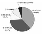
Translated fromKorean도 1은 금형기술의 수요분야 분포도,1 is a distribution chart of the demand field of the mold technology,
도 2는 본 발명의 일실시예에 따른 스마트 금형의 개념도,2 is a conceptual diagram of a smart mold according to an embodiment of the present invention,
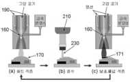
도 3은 본 발명에 사용된 초음속 분사적층 장치의 구조도,3 is a structural diagram of a supersonic jet lamination apparatus used in the present invention,
도 4는 본 발명의 일실시예에 따른 적층 및 절삭 공정의 개념도,4 is a conceptual diagram of a lamination and cutting process according to an embodiment of the present invention;
도 5는 본 발명에 시용되는 금형 보수 장비의 구조도,5 is a structural diagram of a mold repair equipment used in the present invention,
도 6a는 본 발명의 일실시예에 따른 파손전 금형의 원형 사진,Figure 6a is a circular picture of the mold before breakage, according to an embodiment of the present invention,
도 6b는 본 발명의 일실시예에 따른 금형의 돌출부위가 파손된 사진과 단면도,6b is a photograph and a cross-sectional view of the protrusion of the mold broken in accordance with an embodiment of the present invention;
도 6c는 본 발명의 일실시예에 따른 금형의 파손된 부위에 초음속 분사적층으로 20계열 알루미늄 분말을 적층한 사진과 단면도,Figure 6c is a photograph and a cross-sectional view of laminating 20 series aluminum powder in supersonic jet lamination on the damaged part of the mold according to an embodiment of the present invention;
도 6d는 본 발명의 일실시예에 따른 금형을 제작할 때 사용하였던 공구경로와 동일한 공구경로를 이용하여 파손된 부위에 적층된 알루미늄을 CNC절삭 가공하는 사진과 단면도,6d is a photograph and a cross-sectional view of CNC cutting aluminum laminated on a broken part using the same tool path as the tool path used when manufacturing a mold according to an embodiment of the present invention.
도 6e는 본 발명의 일실시예에 따른 초음속 분사 적층기술을 이용하여 원형과 동일하게 복원이 완료된 금형의 사진과 단면도,6E is a photograph and a cross-sectional view of a mold in which restoration is completed in the same manner as a circular shape using a supersonic spray lamination technology according to an embodiment of the present invention;
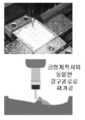
도 7a는 본 발명의 다른 실시예에 따른 냉각채널이 장치된 알루미늄 금형의 제작 공정도,Figure 7a is a manufacturing process of the aluminum mold equipped with a cooling channel according to another embodiment of the present invention,
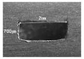
도 7b는 도7a의 보조재료를 제거한 완성된 냉각채널의 단면사진이다.FIG. 7B is a cross-sectional photograph of the completed cooling channel with the auxiliary material of FIG. 7A removed.
<도면의 주요부분에 대한 부호설명><Code Description of Main Parts of Drawing>
110: 고압질소 공급기120: 가스제어 모듈110: high pressure nitrogen supply 120: gas control module
130: 분말재료 공급기140: 가스혼합재료예열기130: powder material feeder 140: gas mixed material preheater
150: 가스예열기160: 초음속 노즐150: gas preheater 160: supersonic nozzle
170: 적층된 재료171: 보조재료170: laminated material 171: auxiliary material
190:열선210: 고속스핀들230: 엔드밀190: hot wire 210: high speed spindle 230: end mill
본 발명은 초음속 분사 적층기술을 이용한 금형의 보수 방법에 관한 것으로서, 보다 상세하게는 금형의 마모 또는 훼손된 부위에 알루미늄, 티타늄 등의 금속입자를 초음속으로 분사하여 적층한 뒤, 정밀 CNC 절삭가공으로 금형을 원형과 동일하게 복구하거나, 생산성을 향상시키기 위하여 금형에 냉각채널 등의 특별한 구조를 삽입하는 금형의 보수 방법에 관한 것이다.The present invention relates to a method for repairing a mold using a supersonic spray lamination technology, and more particularly, by laminating metal particles such as aluminum and titanium at a supersonic speed on a worn or damaged part of a mold, and then molding the mold by precision CNC cutting. To repair the same as the original form, or to insert a special structure such as cooling channels in the mold in order to improve the productivity of the mold repair method.
금형의 제작/ 기술은 각종 부품생산에 있어 필수적인 기술로서 자동차, 통신기기, 전자제품, 반도체, 공작기계 등 도1과 같이 다양한 분야에서 지속적으로 수 요가 증가하고 있는데, 특히 전자제품, 통신기기, 반도체 산업에서 소형 정밀금형의 수요가 급증하면서 금형기술은 정밀화 추세로 발전하고 있다.Mold manufacturing / technology is an essential technology for the production of various parts and is continuously increasing in various fields such as automobiles, communication devices, electronic products, semiconductors, and machine tools as shown in FIG. 1, in particular, electronic products, communication devices, and semiconductors. As the demand for small precision molds increases in the industry, mold technology is developing into a trend of precision.
이러한 금형기술은 제품 및 금형설계기술과 정밀 가공 및 조립기술, 품질 및 유지보수 등의 주요기술로 구성되는데 우리나라는 기술의 인식부족과 품질의 불균일성, 소재품질의 낙후성 등으로 금형 선진국인 미국, 일본에 비하여 표1과 같이 기술수준의 격차를 보이고 있다.This mold technology consists of major technologies such as product and mold design technology, precision processing and assembly technology, quality and maintenance, etc. In Korea, due to lack of technology recognition, quality non-uniformity, and poor quality of material, USA, Japan Compared to Table 1, the gap in technology level is shown.

출처 : 한국생산기술연구원 금형기술종합지원센터(2000.11.09) Source: Korea Molding Technology Support Center (2000.11.09)
종래에는 파손 또는 마모된 금형의 보수시, 전기적 접점을 이용하여 용접후 연마하여 보수하는 방법(특허출원 1993-0004080)을 사용하였으나, 용접재와 금형의 재질이 다르고, 용접부에 발생하는 열의 영향으로 치밀한 조직을 가지지 못하는 단점이 있다.Conventionally, when repairing a damaged or worn mold, a method of repairing by polishing after welding using an electrical contact (patent application 1993-0004080) has been used. However, due to the influence of heat generated on the weld part and the material of the mold, There is a drawback to not having a dense organization.
용접재와 금형 재질이 다르고 용접부에 열영향부 때문에 다시 파손되기 쉬운 문제를 해결하여 반영구적인 보수를 가능하게 하고자, 재료 조성비가 다른 재료를 점짐적으로 코팅하는 방법(특허출원 1995-056810) 즉, 금형재 가공 및 사용시 일부 파손된 부위를 보수하기 위하여 조성을 점진적으로 변화시켜 육성코팅한 후, 코팅층과 모재간에 점착력 향상을 위해서 확산열처리 싸이클로 확산열처리하고, 가공연마하여 만드는 경사육성 코팅 및 확산접합시키는 파손금형 보수 방법이 개발 되었으나,이 방법 또한 정밀 금형의 보수 방법으로는 적합하지 못하다.In order to solve semi-permanent repair by solving the problem that the welding material is different from the material of the mold and easily damaged due to the heat-affecting part of the welding part, a method of gradually coating a material having a different material composition ratio (Patent application 1995-056810) In order to repair some damaged parts during the processing and use of mold materials, the composition is gradually raised and coated, followed by the diffusion heat treatment cycle to improve adhesion between the coating layer and the base material, and the warp-grown coating and diffusion bonding made by processing and polishing. Although the mold repair method has been developed, this method is also not suitable as a method for repairing a precision mold.
또한, 종래 방법으로는 도2에 도시된 바와 같은 금형 내부에 열팽창을 최소화 하기 위한 센서를 삽입하거나, 생산성을 향상시키기 위해 냉각채널을 배치하는 등의 새로운 개념의 스마트 금형은 제작이 불가하다. In addition, according to the conventional method, it is impossible to manufacture a new mold of a new concept such as inserting a sensor for minimizing thermal expansion into a mold as shown in FIG. 2 or arranging a cooling channel to improve productivity.
따라서, 본 발명은 이와 같은 문제점을 감안한 것으로써, 본 발명의 목적은 초음속 분사 적층 기술과 정밀 CNC(Computer Numerical Control, 컴퓨터 제어 가공) 절삭가공 기술을 이용하여 금형 재질의 변화가 없으면서도 정밀하게 원형을 복구할 수 있고, 열변형 제어와 냉각기능이 포함된 스마트 금형 등의 특수한 금형을 제작할 수 있는 초음속 분사 적층기술을 이용한 금형의 보수 방법을 제공함에 있다.Accordingly, the present invention has been made in view of the above problems, and an object of the present invention is to precisely round a mold without changing mold materials by using a supersonic injection lamination technology and a precision CNC (Computer Numerical Control) cutting technology. It is to provide a method of repairing a mold using a supersonic spray lamination technology capable of recovering and manufacturing a special mold such as a smart mold including heat deformation control and cooling function.
상기 목적을 달성하기 위한 본 발명에 의한 금형의 보수방법은, (a) 초음속 분사 적층 장치를 이용하여 금형의 마모 또는 훼손된 부위에 금속입자를 초음속으로 분사하여 적층하는 단계; (b) 상기 적층된 금속입자에 절삭 공구를 이용하여 내부 채널을 형성하는 단계; (c) 상기 내부 채널에 보조재료를 주입하는 단계; (d) 상기 보조재료가 주입된 상기 금속입자에 상기 초음속 분사 적층 장치를 이용하여 동일한 금속입자를 초음속으로 분사하여 적층하는 단계; (e) 상기 적층된 금속입자를 절삭 공구를 이용하여 원형의 형상으로 가공하는 단계; 및 (f) 상기 보조재료를 제거하는 단계;를 포함하는 것을 특징으로 한다.
또한, 상기 목적을 달성하기 위한 본 발명에 의한 다른 금형의 보수방법은, (a) 초음속 분사 적층 장치를 이용하여 금형의 마모 또는 훼손된 부위에 금속입자를 초음속으로 분사하여 적층하는 단계; (b) 상기 적층된 금속입자에 절삭 공구를 이용하여 내부 공간을 형성한 후 상기 내부 공간에 온도센서나 히터와 같은 재료를 삽입하는 단계; (c) 상기 온도센서나 히터와 같은 재료가 삽입된 부분에 상기 초음속 분사 적층 장치를 이용하여 동일한 금속입자를 초음속으로 분사하여 적층하는 단계; 및 (d) 상기 적층된 금속입자를 절삭 공구를 이용하여 원형의 형상으로 가공하는 단계;를 포함하는 것을 특징으로 한다.
상기 금속입자는 고압의 헬륨 또는 질소가스에 의하여 노즐을 통과하며, 300℃~400℃의 낮은 온도에서 분사되어 적층되는 것을 특징으로 한다.
상기 금속입자는 알루미늄, 구리, 텅스텐, 티타늄 중 어느 하나인 것을 특징으로 한다.The method for repairing a mold according to the present invention for achieving the above object comprises the steps of: (a) supersonic injection laminating apparatus by spraying and laminating metal particles in supersonic speed to a worn or damaged part of the mold; (b) forming internal channels on the stacked metal particles by using a cutting tool; (c) injecting auxiliary material into the inner channel; (d) spraying and depositing the same metal particles at supersonic speed on the metal particles into which the auxiliary material is injected by using the supersonic spray laminating apparatus; (e) processing the laminated metal particles into a circular shape using a cutting tool; And (f) removing the auxiliary material.
In addition, another method for repairing a mold according to the present invention for achieving the above object, (a) using a supersonic spray lamination apparatus by spraying the metal particles to the worn or damaged parts of the mold by supersonic lamination; (b) inserting a material such as a temperature sensor or a heater into the inner space by forming an inner space using a cutting tool in the stacked metal particles; (c) spraying and depositing the same metal particles at a supersonic speed using the supersonic jet lamination apparatus in a portion where a material such as the temperature sensor or heater is inserted; And (d) processing the stacked metal particles into a circular shape by using a cutting tool.
The metal particles are passed through the nozzle by a high pressure helium or nitrogen gas, it characterized in that the injection is laminated at a low temperature of 300 ℃ ~ 400 ℃.
The metal particles are characterized in that any one of aluminum, copper, tungsten, titanium.
삭제delete
삭제delete
삭제delete
삭제delete
삭제delete
삭제delete
이하, 첨부된 도면을 참고로 하여 본 발명에 따른 초음속 분사 적층기술을 이용한 금형의 보수 방법에 대해 상세하게 설명한다.Hereinafter, with reference to the accompanying drawings will be described in detail for the repair method of the mold using the supersonic spray lamination technology according to the present invention.
도 3은 본 발명에 사용된 초음속 분사적층 장치의 구조도, 도 4는 본 발명의 일실시예에 따른 적층 및 절삭 공정의 개념도, 도 5는 본 발명에 시용되는 금형 보수 장비의 구조도이다. 3 is a structural diagram of a supersonic jet lamination apparatus used in the present invention, FIG. 4 is a conceptual diagram of a laminating and cutting process according to an embodiment of the present invention, and FIG. 5 is a structural diagram of a mold repairing equipment used in the present invention.
도3 내지 도5를 참조하면, 본 발명의 일실시예에 따른 금형 보수방법은, 금형의 마모 또는 훼손된 부위에 금속입자를 초음속으로 분사하여 적층하는 단계; 및 절삭 공구를 이용하여 금형 원형의 형상으로 가공하는 단계를 포함하여 구성된다.3 to 5, a mold repairing method according to an embodiment of the present invention includes the steps of laminating by spraying metal particles at a supersonic speed on a worn or damaged part of a mold; And processing to a mold circular shape using a cutting tool.
우선, 금형의 마모 또는 훼손된 부위에 금속입자를 고압의 헬륨 또는 질소가스에 의하여 노즐(160)을 통과시켜 마하 1.5~2정도의 초음속으로 분사·적층하는데, 이때, 금속입자의 높은 운동에너지가 순간적인 열 에너지로 바뀌어 금속입자를 상기 마모 또는 훼손 부위에 치밀하게 결합시키게 되는 것이다.First, the metal particles are sprayed and laminated at a supersonic speed of about Mach 1.5 to 2 by passing the
상기 금속입자 적층은 약 300℃~400℃의 낮은 온도에서 이루어지는 바, 금형 보수시 모재의 열변형을 최소화한다.The metal particle lamination is performed at a low temperature of about 300 ℃ to 400 ℃ bar to minimize the thermal deformation of the base material during the mold repair.
다음으로, CNC 절삭으로 금형의 형상을 원형과 동일하게 복원하거나 새로운 형태의 금형을 제작한다.Next, CNC cutting restores the shape of the mold to its original shape or manufactures a new mold.
또한, 금형 보수시 금형의 형상은 금형을 설계할 당시의 캐드파일을 이용하여 공구경로(NC코드)를 생성하게 되고, 생성된 공구경로에 따라 CNC 가공기로 평 엔드밀(230) 또는 볼 엔드밀을 이용하여 정밀하게 가공함으로써 금형의 원형과 동일하게 복구하게된다(도3 내지 도5에 도시된 본 발명에서 사용한 초음속 분사 장치의 기계적 구성은 본 발명의 특징적인 부분이 아니며, 권리범위로 청구하는 부분이 아니므로, 도면 부호에 대한 구체적 설명은 생략한다.).In addition, during mold repair, the shape of the mold generates a tool path (NC code) using a CAD file at the time of designing the mold, and according to the generated tool path, the
본 발명의 다른 실시예에 따른 금형 제작 방법은, 열변형을 최소화 하거나 생산성을 향상시키기 위한 스마트 금형을 제작하는 것으로서, 우선 초음속 분사적층을 이용하여 금속입자(170)를 분사·적층한 후, 절삭 가공을 이용하여 내부공간을 가공한 후 상기 내부공간에 온도센서나 히터와 같은 재료를 삽입하고, 상기 온도센서나 히터와 같은 재료가 삽입된 부분에 상기 초음속 분사 적층 장치를 이용하여 동일한 금속입자를 초음속으로 분사하여 적층한 다음, 상기 적층된 금속입자를 절삭 공구를 이용하여 원형의 형상으로 가공함으로써 금형 보수를 완료한다.
상기 금속입자(170)는 수십 나노미터(㎚)에서 수백 마이크로미터(㎛)의 직경을 가지는 입자로서, 알루미늄, 구리, 텅스텐, 티타늄 등울 사용하는 것이 바람직하다. 그러나, 상기 재료에 제한되는 것은 아니며, 세라믹 재료나 고분자 화합물등도 사용할 수 있다.According to another embodiment of the present invention, a mold manufacturing method is to manufacture a smart mold for minimizing thermal deformation or improving productivity. First, after spraying and laminating
The
삭제delete
이때, 상기 보조재료는 다시 제거하는 후 공정을 고려하여, 비스무스(Bi)와 틴(Sn)을 7:4로 혼합한 비스무스틴을 사용하는 것이 바람직하다.In this case, it is preferable to use bismustin mixed with bismuth (Bi) and tin (Sn) at 7: 4 in consideration of a post-removal process.
즉, 본 발명에 따른 초음속 분사적층을 이용한 금형의 보수 방법은 약 300℃~400℃의 낮은 온도에서, 알루미늄이나 구리, 텅스텐, 티타늄등의 금속 입자를 초음속으로 분사하여 적층한 후에, CNC 절삭가공을 통하여 금형의 원형을 회복하거나 새로운 금형을 제작하는 것이다. 이에 따라, 연마 등의 후처리 공정이 불필요하다.That is, in the repairing method of the mold using the supersonic spray lamination according to the present invention, the CNC cutting process is performed by supersonically spraying and laminating metal particles such as aluminum, copper, tungsten and titanium at a low temperature of about 300 ° C to 400 ° C. Through the recovery of the original mold or to manufacture a new mold. As a result, post-treatment steps such as polishing are unnecessary.
이하에서는 실시예를 통하여 본 발명을 좀 더 상세하게 설명하기는 하나, 하기의 실시예는 본 발명의 예시일 뿐, 본 발명이 하기의 실시예에 의하여 제한되는 것은 아니다.
<실시예1 : 초음속 분사 적층기술을 이용한 금형의 보수>Hereinafter, the present invention will be described in more detail with reference to Examples, but the following Examples are merely illustrative of the present invention, and the present invention is not limited by the following Examples.
Example 1 Repair of a Mold Using Supersonic Spray Lamination Technology
삭제delete
도2a 및 도6b에 도시된 바와 같이, 20계열 알루미늄으로 제작된 40X40X12(mm) 크기의 금형 중앙에 위치한 직경 8mm의 돌출부가 파손된 금형을 초음속 적층기술을 이용하여 보수하는 것이다.As shown in Figures 2a and 6b, by repairing the mold damaged by the protrusion of the diameter of 8mm located in the center of the 40X40X12 (mm) size made of 20 series aluminum using supersonic lamination technology.
우선, 20계열 알루미늄 분말을 마하 1.5의 초음속으로 분사(350℃)하여 적층한 후(도 6c)에, 금형을 제작하였던 동일한 공구경로(NC 코드)를 이용하여 금형의 원형과 동일하게 절삭 가공(도6d)하여 파손된 금형을 복구(도6e)하였다.First, 20 series aluminum powder was sprayed (350 ° C) at a supersonic speed of Mach 1.5 and laminated (FIG. 6C), and then cut in the same manner as the original shape of the mold using the same tool path (NC code) in which the mold was manufactured. 6d), the broken mold was recovered (Fig. 6e).
상기 20계열 알루미늄은 알루미늄과 구리혼합의 합금으로서, 구리 함량이 2.5 ~ 5.5% 인 것을 사용하였다.The 20 series aluminum is an alloy of aluminum and copper mixture, the copper content of 2.5 to 5.5% was used.
<실시예2 : 초음속 분사 적층기술을 이용한 스마트 금형의 제작>Example 2 Fabrication of Smart Mold Using Supersonic Spray Lamination Technology
초음속 적층기술을 이용하여 스마트 금형(도2 참조)을 제작하는 방법중, 마이크로 냉각채널을 제작하는 과정이다.In the method of manufacturing a smart mold (see FIG. 2) using supersonic lamination technology, a micro cooling channel is manufactured.
우선, 20계열 알루미늄 판에 동일한 재료인 20계열 알루미늄 분말을 마하 1.5의 초음속으로 분사(350℃)하여 적층하고(도7a-1), 정밀 절삭 공구를 이용하여 냉각채널을 가공(도7a-2)한 다음, 상술한 비스무스틴을 보조재료로 사용하여 채널의 빈 공간을 채운후(도7a-3)에 다시 20계열 알루미늄 분말을 분사적층(도7a-4)하였다. 마지막으로, 채널의 빈 공간에 채워진 보조재료를 제거(도7a-5)하여 스마트 금형의 냉각채널을 완성하였다(도7b).First, 20 series aluminum powder, which is the same material, is laminated on a 20 series aluminum plate by spraying (350 ° C) at a supersonic speed of Mach 1.5 (FIG. 7A-1), and processing a cooling channel using a precision cutting tool (FIG. 7A-2). Next, after filling the empty space of the channel using the above-mentioned bismustine as an auxiliary material (FIG. 7A-3), 20 series aluminum powder was spray-laminated again (FIG. 7A-4). Finally, the auxiliary material filled in the empty space of the channel was removed (FIGS. 7A-5) to complete the cooling channel of the smart mold (FIG. 7B).
본 발명은 상기 실시예에 한정되지 않으며 당해 기술이 속한 분야에서의 통상의 지식을 가진 자에 의하여 본 발명의 기술적 사상 내에서 많은 변형에 의한 실시 가능함은 명백하다.It is apparent that the present invention is not limited to the above embodiments and can be implemented by many modifications within the technical idea of the present invention by those skilled in the art.
이와 같이 본 발명에 의한 초음속 분사적층을 이용한 금형의 보수 방법은 300℃~400℃의 낮은 온도에서, 알루미늄이나 구리, 텅스텐, 티타늄등의 금속 입자를 초음속으로 분사하여 적층한 후에, CNC 절삭가공을 통하여 금형의 원형을 회복하거나 새로운 금형을 제작하는 것이므로, 다음과 같은 효과가 있다.As described above, the repairing method of the mold using the supersonic spray lamination according to the present invention is carried out at a low temperature of 300 ° C. to 400 ° C. by spraying and laminating metal particles such as aluminum, copper, tungsten and titanium at supersonic speed, and then performing CNC cutting. Through restoring the original shape of the mold or making a new mold, the following effects are obtained.
우선, 용접재와 금형의 재질이 동일하며 저온 적층이 가능한 바, 용접부에 발생하는 열의 영향으로 치밀한 조직을 가지지 못하는 단점을 가진 종래 기술과는 달리 금형 보수시에 모재의 열변형을 최소화 할 수 있다.First, since the material of the welding material and the mold is the same, and low-temperature lamination is possible, the thermal deformation of the base material can be minimized when the mold is repaired, unlike the prior art, which has the disadvantage of not having a dense structure due to the heat generated in the weld. .
반영구적인 보수가 가능하며, 연마 등의 후처리 공정이 불필요하다.Semi-permanent repair is possible, and post-treatment such as polishing is unnecessary.
정밀 CNC기계를 사용하는 바, 금형 내부에 열팽창을 최소화 하기 위한 센서를 삽입하거나, 생산성을 향상시키기 위해 냉각채널을 배치하는 등 스마트 금형도 제작할 수 있다.Using a precision CNC machine, smart molds can be manufactured by inserting sensors to minimize thermal expansion inside the mold or by placing cooling channels to improve productivity.
Claims (7)
Translated fromKoreanPriority Applications (1)
| Application Number | Priority Date | Filing Date | Title |
|---|---|---|---|
| KR1020050048072AKR100683124B1 (en) | 2005-06-04 | 2005-06-04 | Mold repair method using supersonic spray lamination technology |
Applications Claiming Priority (1)
| Application Number | Priority Date | Filing Date | Title |
|---|---|---|---|
| KR1020050048072AKR100683124B1 (en) | 2005-06-04 | 2005-06-04 | Mold repair method using supersonic spray lamination technology |
Publications (2)
| Publication Number | Publication Date |
|---|---|
| KR20060126293A KR20060126293A (en) | 2006-12-07 |
| KR100683124B1true KR100683124B1 (en) | 2007-02-15 |
Family
ID=37730267
Family Applications (1)
| Application Number | Title | Priority Date | Filing Date |
|---|---|---|---|
| KR1020050048072AExpired - Fee RelatedKR100683124B1 (en) | 2005-06-04 | 2005-06-04 | Mold repair method using supersonic spray lamination technology |
Country Status (1)
| Country | Link |
|---|---|
| KR (1) | KR100683124B1 (en) |
Cited By (5)
| Publication number | Priority date | Publication date | Assignee | Title |
|---|---|---|---|---|
| US8961867B2 (en) | 2008-09-09 | 2015-02-24 | H.C. Starck Inc. | Dynamic dehydriding of refractory metal powders |
| US9095932B2 (en) | 2006-12-13 | 2015-08-04 | H.C. Starck Inc. | Methods of joining metallic protective layers |
| US9108273B2 (en) | 2011-09-29 | 2015-08-18 | H.C. Starck Inc. | Methods of manufacturing large-area sputtering targets using interlocking joints |
| US9714470B2 (en) | 2013-03-05 | 2017-07-25 | Kia Motors Corporation | Method and system for die compensation and restoration using high-velocity oxy-fuel thermal spray coating and plasma ion nitriding |
| US9783882B2 (en) | 2007-05-04 | 2017-10-10 | H.C. Starck Inc. | Fine grained, non banded, refractory metal sputtering targets with a uniformly random crystallographic orientation, method for making such film, and thin film based devices and products made therefrom |
Families Citing this family (6)
| Publication number | Priority date | Publication date | Assignee | Title |
|---|---|---|---|---|
| KR100815998B1 (en)* | 2006-09-19 | 2008-03-21 | 재단법인 포항산업과학연구원 | Maintenance method of playing mold |
| KR100971247B1 (en)* | 2007-12-21 | 2010-07-20 | 주식회사 포스코 | How to repair damaged parts of performance copper mold |
| KR101242610B1 (en)* | 2010-10-29 | 2013-03-20 | (주)태광테크 | Cooling substrate of electronic component for radiating heat and producing method thereof |
| KR101647890B1 (en)* | 2014-10-28 | 2016-08-12 | 한국생산기술연구원 | Method to manufacture cooling block for hot stamping metallic pattern using three dimensional metal-print |
| WO2022263825A1 (en)* | 2021-06-18 | 2022-12-22 | Bae Systems Plc | Method of making a composite mould tool and repairing method of a composite mould tool |
| KR102524076B1 (en)* | 2022-12-29 | 2023-04-21 | (주)서영 | 3D Printing Method for Repairing Mold |
Citations (1)
| Publication number | Priority date | Publication date | Assignee | Title |
|---|---|---|---|---|
| KR19980061894A (en)* | 1996-12-31 | 1998-10-07 | 오상수 | Inner diameter injection thick film coding method and apparatus |
- 2005
- 2005-06-04KRKR1020050048072Apatent/KR100683124B1/ennot_activeExpired - Fee Related
Patent Citations (1)
| Publication number | Priority date | Publication date | Assignee | Title |
|---|---|---|---|---|
| KR19980061894A (en)* | 1996-12-31 | 1998-10-07 | 오상수 | Inner diameter injection thick film coding method and apparatus |
Non-Patent Citations (1)
| Title |
|---|
| 1019980061894 |
Cited By (9)
| Publication number | Priority date | Publication date | Assignee | Title |
|---|---|---|---|---|
| US9095932B2 (en) | 2006-12-13 | 2015-08-04 | H.C. Starck Inc. | Methods of joining metallic protective layers |
| US9783882B2 (en) | 2007-05-04 | 2017-10-10 | H.C. Starck Inc. | Fine grained, non banded, refractory metal sputtering targets with a uniformly random crystallographic orientation, method for making such film, and thin film based devices and products made therefrom |
| US8961867B2 (en) | 2008-09-09 | 2015-02-24 | H.C. Starck Inc. | Dynamic dehydriding of refractory metal powders |
| US9108273B2 (en) | 2011-09-29 | 2015-08-18 | H.C. Starck Inc. | Methods of manufacturing large-area sputtering targets using interlocking joints |
| US9120183B2 (en) | 2011-09-29 | 2015-09-01 | H.C. Starck Inc. | Methods of manufacturing large-area sputtering targets |
| US9293306B2 (en) | 2011-09-29 | 2016-03-22 | H.C. Starck, Inc. | Methods of manufacturing large-area sputtering targets using interlocking joints |
| US9412568B2 (en) | 2011-09-29 | 2016-08-09 | H.C. Starck, Inc. | Large-area sputtering targets |
| US9714470B2 (en) | 2013-03-05 | 2017-07-25 | Kia Motors Corporation | Method and system for die compensation and restoration using high-velocity oxy-fuel thermal spray coating and plasma ion nitriding |
| US10407776B2 (en) | 2013-03-05 | 2019-09-10 | Hyundai Motor Company | Method and system for die compensation and restoration using high-velocity oxy-fuel thermal spray coating and plasma ion nitriding |
Also Published As
| Publication number | Publication date |
|---|---|
| KR20060126293A (en) | 2006-12-07 |
Similar Documents
| Publication | Publication Date | Title |
|---|---|---|
| KR100683124B1 (en) | Mold repair method using supersonic spray lamination technology | |
| US6593171B2 (en) | Stereolithographic methods for fabricating hermetic semiconductor device packages and semiconductor devices including stereolithographically fabricated hermetic packages | |
| US8021715B2 (en) | Cold gas spraying method | |
| US11104068B2 (en) | Method for enhancing the finish of additively-manufactured components | |
| Weiss et al. | Thermal spray shape deposition | |
| US20220297215A1 (en) | Wire arc hybrid manufacturing | |
| EP3375007A1 (en) | Sputter target backing plate assemblies with cooling structures | |
| CN108161009A (en) | A kind of precinct laser cladding and grinding In-situ reaction manufacturing device | |
| JP2013510235A (en) | Support plate for laser sintering apparatus and improved sintering method | |
| CN107570707A (en) | Plasma increases the 3D printing equipment of material and laser cutting | |
| Kumbhar et al. | Finishing of fused deposition modelling (FDM) printed parts by CO2 laser | |
| US10449624B2 (en) | Method of fabrication for the repair and augmentation of part functionality of metallic components | |
| KR102498148B1 (en) | Method for fabricating a semiconductor device | |
| KR20080010086A (en) | Busbar manufacturing method using low temperature spray coating | |
| CN110576602B (en) | 3D printing method of polyether-ether-ketone and printing sample piece thereof | |
| CN108655407A (en) | A kind of ultra-fine grain carrier fluid injection microwave sintering manufacturing process | |
| KR102643378B1 (en) | Method and equipment for manufacturing three-dimensional objects | |
| TWI382920B (en) | Method for manufacturing mold for optical element forming | |
| CN108050824A (en) | Integrated air knife and its increasing material manufacturing method | |
| KR20160055989A (en) | Internal member applying plasma treatment apparatus and method for manufacturing the same | |
| KR101456830B1 (en) | Apparatus and process for producing three-dimensional object | |
| Macovei et al. | A review on tribological behaviour of mechanical components obtained by additive manufacturing | |
| KR101413530B1 (en) | Cmp pad conditioner and its manufacturing method | |
| Dasdemir et al. | Metal based additive manufacturing | |
| KR20090067636A (en) | System for coating the copper plate of continuous casting mold by the jet of low temperature and low pressure |
Legal Events
| Date | Code | Title | Description |
|---|---|---|---|
| A201 | Request for examination | ||
| PA0109 | Patent application | St.27 status event code:A-0-1-A10-A12-nap-PA0109 | |
| PA0201 | Request for examination | St.27 status event code:A-1-2-D10-D11-exm-PA0201 | |
| D13-X000 | Search requested | St.27 status event code:A-1-2-D10-D13-srh-X000 | |
| D14-X000 | Search report completed | St.27 status event code:A-1-2-D10-D14-srh-X000 | |
| E902 | Notification of reason for refusal | ||
| PE0902 | Notice of grounds for rejection | St.27 status event code:A-1-2-D10-D21-exm-PE0902 | |
| T11-X000 | Administrative time limit extension requested | St.27 status event code:U-3-3-T10-T11-oth-X000 | |
| E13-X000 | Pre-grant limitation requested | St.27 status event code:A-2-3-E10-E13-lim-X000 | |
| P11-X000 | Amendment of application requested | St.27 status event code:A-2-2-P10-P11-nap-X000 | |
| P13-X000 | Application amended | St.27 status event code:A-2-2-P10-P13-nap-X000 | |
| E701 | Decision to grant or registration of patent right | ||
| PE0701 | Decision of registration | St.27 status event code:A-1-2-D10-D22-exm-PE0701 | |
| PG1501 | Laying open of application | St.27 status event code:A-1-1-Q10-Q12-nap-PG1501 | |
| GRNT | Written decision to grant | ||
| PR0701 | Registration of establishment | St.27 status event code:A-2-4-F10-F11-exm-PR0701 | |
| PR1002 | Payment of registration fee | St.27 status event code:A-2-2-U10-U11-oth-PR1002 Fee payment year number:1 | |
| PG1601 | Publication of registration | St.27 status event code:A-4-4-Q10-Q13-nap-PG1601 | |
| PN2301 | Change of applicant | St.27 status event code:A-5-5-R10-R11-asn-PN2301 | |
| PN2301 | Change of applicant | St.27 status event code:A-5-5-R10-R14-asn-PN2301 | |
| PN2301 | Change of applicant | St.27 status event code:A-5-5-R10-R11-asn-PN2301 | |
| PN2301 | Change of applicant | St.27 status event code:A-5-5-R10-R14-asn-PN2301 | |
| R18-X000 | Changes to party contact information recorded | St.27 status event code:A-5-5-R10-R18-oth-X000 | |
| PR1001 | Payment of annual fee | St.27 status event code:A-4-4-U10-U11-oth-PR1001 Fee payment year number:4 | |
| PR1001 | Payment of annual fee | St.27 status event code:A-4-4-U10-U11-oth-PR1001 Fee payment year number:5 | |
| PR1001 | Payment of annual fee | St.27 status event code:A-4-4-U10-U11-oth-PR1001 Fee payment year number:6 | |
| FPAY | Annual fee payment | Payment date:20130102 Year of fee payment:7 | |
| PR1001 | Payment of annual fee | St.27 status event code:A-4-4-U10-U11-oth-PR1001 Fee payment year number:7 | |
| FPAY | Annual fee payment | Payment date:20140103 Year of fee payment:8 | |
| PR1001 | Payment of annual fee | St.27 status event code:A-4-4-U10-U11-oth-PR1001 Fee payment year number:8 | |
| R18-X000 | Changes to party contact information recorded | St.27 status event code:A-5-5-R10-R18-oth-X000 | |
| FPAY | Annual fee payment | Payment date:20141226 Year of fee payment:9 | |
| PR1001 | Payment of annual fee | St.27 status event code:A-4-4-U10-U11-oth-PR1001 Fee payment year number:9 | |
| R18-X000 | Changes to party contact information recorded | St.27 status event code:A-5-5-R10-R18-oth-X000 | |
| P14-X000 | Amendment of ip right document requested | St.27 status event code:A-5-5-P10-P14-nap-X000 | |
| PN2301 | Change of applicant | St.27 status event code:A-5-5-R10-R11-asn-PN2301 | |
| PN2301 | Change of applicant | St.27 status event code:A-5-5-R10-R14-asn-PN2301 | |
| P14-X000 | Amendment of ip right document requested | St.27 status event code:A-5-5-P10-P14-nap-X000 | |
| P16-X000 | Ip right document amended | St.27 status event code:A-5-5-P10-P16-nap-X000 | |
| Q16-X000 | A copy of ip right certificate issued | St.27 status event code:A-4-4-Q10-Q16-nap-X000 | |
| FPAY | Annual fee payment | Payment date:20151125 Year of fee payment:10 | |
| PR1001 | Payment of annual fee | St.27 status event code:A-4-4-U10-U11-oth-PR1001 Fee payment year number:10 | |
| P22-X000 | Classification modified | St.27 status event code:A-4-4-P10-P22-nap-X000 | |
| FPAY | Annual fee payment | Payment date:20170201 Year of fee payment:11 | |
| PR1001 | Payment of annual fee | St.27 status event code:A-4-4-U10-U11-oth-PR1001 Fee payment year number:11 | |
| FPAY | Annual fee payment | Payment date:20180206 Year of fee payment:12 | |
| PR1001 | Payment of annual fee | St.27 status event code:A-4-4-U10-U11-oth-PR1001 Fee payment year number:12 | |
| P22-X000 | Classification modified | St.27 status event code:A-4-4-P10-P22-nap-X000 | |
| P22-X000 | Classification modified | St.27 status event code:A-4-4-P10-P22-nap-X000 | |
| FPAY | Annual fee payment | Payment date:20190307 Year of fee payment:13 | |
| PR1001 | Payment of annual fee | St.27 status event code:A-4-4-U10-U11-oth-PR1001 Fee payment year number:13 | |
| PC1903 | Unpaid annual fee | St.27 status event code:A-4-4-U10-U13-oth-PC1903 Not in force date:20200209 Payment event data comment text:Termination Category : DEFAULT_OF_REGISTRATION_FEE | |
| PC1903 | Unpaid annual fee | St.27 status event code:N-4-6-H10-H13-oth-PC1903 Ip right cessation event data comment text:Termination Category : DEFAULT_OF_REGISTRATION_FEE Not in force date:20200209 |