KR100682920B1 - Multi-bioassay microfluidic chip and its manufacturing method - Google Patents
Multi-bioassay microfluidic chip and its manufacturing methodDownload PDFInfo
- Publication number
- KR100682920B1 KR100682920B1KR1020050005533AKR20050005533AKR100682920B1KR 100682920 B1KR100682920 B1KR 100682920B1KR 1020050005533 AKR1020050005533 AKR 1020050005533AKR 20050005533 AKR20050005533 AKR 20050005533AKR 100682920 B1KR100682920 B1KR 100682920B1
- Authority
- KR
- South Korea
- Prior art keywords
- probe
- channel
- polymer
- immobilization region
- microfluidic
- Prior art date
- Legal status (The legal status is an assumption and is not a legal conclusion. Google has not performed a legal analysis and makes no representation as to the accuracy of the status listed.)
- Expired - Fee Related
Links
Images


Classifications
- B—PERFORMING OPERATIONS; TRANSPORTING
- B82—NANOTECHNOLOGY
- B82Y—SPECIFIC USES OR APPLICATIONS OF NANOSTRUCTURES; MEASUREMENT OR ANALYSIS OF NANOSTRUCTURES; MANUFACTURE OR TREATMENT OF NANOSTRUCTURES
- B82Y30/00—Nanotechnology for materials or surface science, e.g. nanocomposites
- A—HUMAN NECESSITIES
- A61—MEDICAL OR VETERINARY SCIENCE; HYGIENE
- A61H—PHYSICAL THERAPY APPARATUS, e.g. DEVICES FOR LOCATING OR STIMULATING REFLEX POINTS IN THE BODY; ARTIFICIAL RESPIRATION; MASSAGE; BATHING DEVICES FOR SPECIAL THERAPEUTIC OR HYGIENIC PURPOSES OR SPECIFIC PARTS OF THE BODY
- A61H33/00—Bathing devices for special therapeutic or hygienic purposes
- A61H33/06—Artificial hot-air or cold-air baths; Steam or gas baths or douches, e.g. sauna or Finnish baths
- A61H33/063—Heaters specifically designed therefor
- A—HUMAN NECESSITIES
- A61—MEDICAL OR VETERINARY SCIENCE; HYGIENE
- A61H—PHYSICAL THERAPY APPARATUS, e.g. DEVICES FOR LOCATING OR STIMULATING REFLEX POINTS IN THE BODY; ARTIFICIAL RESPIRATION; MASSAGE; BATHING DEVICES FOR SPECIAL THERAPEUTIC OR HYGIENIC PURPOSES OR SPECIFIC PARTS OF THE BODY
- A61H33/00—Bathing devices for special therapeutic or hygienic purposes
- A61H33/0095—Arrangements for varying the temperature of the liquid
- A—HUMAN NECESSITIES
- A61—MEDICAL OR VETERINARY SCIENCE; HYGIENE
- A61H—PHYSICAL THERAPY APPARATUS, e.g. DEVICES FOR LOCATING OR STIMULATING REFLEX POINTS IN THE BODY; ARTIFICIAL RESPIRATION; MASSAGE; BATHING DEVICES FOR SPECIAL THERAPEUTIC OR HYGIENIC PURPOSES OR SPECIFIC PARTS OF THE BODY
- A61H33/00—Bathing devices for special therapeutic or hygienic purposes
- A61H33/06—Artificial hot-air or cold-air baths; Steam or gas baths or douches, e.g. sauna or Finnish baths
- A61H33/10—Devices on tubs for steam baths
- A—HUMAN NECESSITIES
- A61—MEDICAL OR VETERINARY SCIENCE; HYGIENE
- A61H—PHYSICAL THERAPY APPARATUS, e.g. DEVICES FOR LOCATING OR STIMULATING REFLEX POINTS IN THE BODY; ARTIFICIAL RESPIRATION; MASSAGE; BATHING DEVICES FOR SPECIAL THERAPEUTIC OR HYGIENIC PURPOSES OR SPECIFIC PARTS OF THE BODY
- A61H35/00—Baths for specific parts of the body
- A61H35/006—Baths for specific parts of the body for the feet
- A—HUMAN NECESSITIES
- A61—MEDICAL OR VETERINARY SCIENCE; HYGIENE
- A61H—PHYSICAL THERAPY APPARATUS, e.g. DEVICES FOR LOCATING OR STIMULATING REFLEX POINTS IN THE BODY; ARTIFICIAL RESPIRATION; MASSAGE; BATHING DEVICES FOR SPECIAL THERAPEUTIC OR HYGIENIC PURPOSES OR SPECIFIC PARTS OF THE BODY
- A61H39/00—Devices for locating or stimulating specific reflex points of the body for physical therapy, e.g. acupuncture
- A61H39/04—Devices for pressing such points, e.g. Shiatsu or Acupressure
- A—HUMAN NECESSITIES
- A61—MEDICAL OR VETERINARY SCIENCE; HYGIENE
- A61N—ELECTROTHERAPY; MAGNETOTHERAPY; RADIATION THERAPY; ULTRASOUND THERAPY
- A61N5/00—Radiation therapy
- A61N5/06—Radiation therapy using light
- A61N5/0613—Apparatus adapted for a specific treatment
- A61N5/0625—Warming the body, e.g. hyperthermia treatment
- B—PERFORMING OPERATIONS; TRANSPORTING
- B01—PHYSICAL OR CHEMICAL PROCESSES OR APPARATUS IN GENERAL
- B01L—CHEMICAL OR PHYSICAL LABORATORY APPARATUS FOR GENERAL USE
- B01L3/00—Containers or dishes for laboratory use, e.g. laboratory glassware; Droppers
- B01L3/50—Containers for the purpose of retaining a material to be analysed, e.g. test tubes
- B01L3/502—Containers for the purpose of retaining a material to be analysed, e.g. test tubes with fluid transport, e.g. in multi-compartment structures
- B01L3/5025—Containers for the purpose of retaining a material to be analysed, e.g. test tubes with fluid transport, e.g. in multi-compartment structures for parallel transport of multiple samples
- B—PERFORMING OPERATIONS; TRANSPORTING
- B01—PHYSICAL OR CHEMICAL PROCESSES OR APPARATUS IN GENERAL
- B01L—CHEMICAL OR PHYSICAL LABORATORY APPARATUS FOR GENERAL USE
- B01L3/00—Containers or dishes for laboratory use, e.g. laboratory glassware; Droppers
- B01L3/50—Containers for the purpose of retaining a material to be analysed, e.g. test tubes
- B01L3/502—Containers for the purpose of retaining a material to be analysed, e.g. test tubes with fluid transport, e.g. in multi-compartment structures
- B01L3/5027—Containers for the purpose of retaining a material to be analysed, e.g. test tubes with fluid transport, e.g. in multi-compartment structures by integrated microfluidic structures, i.e. dimensions of channels and chambers are such that surface tension forces are important, e.g. lab-on-a-chip
- B01L3/502707—Containers for the purpose of retaining a material to be analysed, e.g. test tubes with fluid transport, e.g. in multi-compartment structures by integrated microfluidic structures, i.e. dimensions of channels and chambers are such that surface tension forces are important, e.g. lab-on-a-chip characterised by the manufacture of the container or its components
- A—HUMAN NECESSITIES
- A61—MEDICAL OR VETERINARY SCIENCE; HYGIENE
- A61H—PHYSICAL THERAPY APPARATUS, e.g. DEVICES FOR LOCATING OR STIMULATING REFLEX POINTS IN THE BODY; ARTIFICIAL RESPIRATION; MASSAGE; BATHING DEVICES FOR SPECIAL THERAPEUTIC OR HYGIENIC PURPOSES OR SPECIFIC PARTS OF THE BODY
- A61H2201/00—Characteristics of apparatus not provided for in the preceding codes
- A61H2201/01—Constructive details
- A61H2201/0119—Support for the device
- A61H2201/0138—Support for the device incorporated in furniture
- A61H2201/0149—Seat or chair
- A—HUMAN NECESSITIES
- A61—MEDICAL OR VETERINARY SCIENCE; HYGIENE
- A61H—PHYSICAL THERAPY APPARATUS, e.g. DEVICES FOR LOCATING OR STIMULATING REFLEX POINTS IN THE BODY; ARTIFICIAL RESPIRATION; MASSAGE; BATHING DEVICES FOR SPECIAL THERAPEUTIC OR HYGIENIC PURPOSES OR SPECIFIC PARTS OF THE BODY
- A61H2203/00—Additional characteristics concerning the patient
- A61H2203/04—Position of the patient
- A61H2203/0425—Sitting on the buttocks
- A61H2203/0431—Sitting on the buttocks in 90°/90°-position, like on a chair
- A—HUMAN NECESSITIES
- A61—MEDICAL OR VETERINARY SCIENCE; HYGIENE
- A61H—PHYSICAL THERAPY APPARATUS, e.g. DEVICES FOR LOCATING OR STIMULATING REFLEX POINTS IN THE BODY; ARTIFICIAL RESPIRATION; MASSAGE; BATHING DEVICES FOR SPECIAL THERAPEUTIC OR HYGIENIC PURPOSES OR SPECIFIC PARTS OF THE BODY
- A61H2205/00—Devices for specific parts of the body
- A61H2205/08—Trunk
- A61H2205/086—Buttocks
- A—HUMAN NECESSITIES
- A61—MEDICAL OR VETERINARY SCIENCE; HYGIENE
- A61H—PHYSICAL THERAPY APPARATUS, e.g. DEVICES FOR LOCATING OR STIMULATING REFLEX POINTS IN THE BODY; ARTIFICIAL RESPIRATION; MASSAGE; BATHING DEVICES FOR SPECIAL THERAPEUTIC OR HYGIENIC PURPOSES OR SPECIFIC PARTS OF THE BODY
- A61H2205/00—Devices for specific parts of the body
- A61H2205/08—Trunk
- A61H2205/087—Genitals
- A—HUMAN NECESSITIES
- A61—MEDICAL OR VETERINARY SCIENCE; HYGIENE
- A61N—ELECTROTHERAPY; MAGNETOTHERAPY; RADIATION THERAPY; ULTRASOUND THERAPY
- A61N5/00—Radiation therapy
- A61N5/06—Radiation therapy using light
- A61N2005/0658—Radiation therapy using light characterised by the wavelength of light used
- A61N2005/0659—Radiation therapy using light characterised by the wavelength of light used infrared
- A61N2005/066—Radiation therapy using light characterised by the wavelength of light used infrared far infrared
- B—PERFORMING OPERATIONS; TRANSPORTING
- B01—PHYSICAL OR CHEMICAL PROCESSES OR APPARATUS IN GENERAL
- B01J—CHEMICAL OR PHYSICAL PROCESSES, e.g. CATALYSIS OR COLLOID CHEMISTRY; THEIR RELEVANT APPARATUS
- B01J2219/00—Chemical, physical or physico-chemical processes in general; Their relevant apparatus
- B01J2219/00274—Sequential or parallel reactions; Apparatus and devices for combinatorial chemistry or for making arrays; Chemical library technology
- B01J2219/00277—Apparatus
- B01J2219/00497—Features relating to the solid phase supports
- B01J2219/00513—Essentially linear supports
- B01J2219/0052—Essentially linear supports in the shape of elongated tubes
- B01J2219/00522—Essentially linear supports in the shape of elongated tubes in a multiple parallel arrangement
- B—PERFORMING OPERATIONS; TRANSPORTING
- B01—PHYSICAL OR CHEMICAL PROCESSES OR APPARATUS IN GENERAL
- B01J—CHEMICAL OR PHYSICAL PROCESSES, e.g. CATALYSIS OR COLLOID CHEMISTRY; THEIR RELEVANT APPARATUS
- B01J2219/00—Chemical, physical or physico-chemical processes in general; Their relevant apparatus
- B01J2219/00274—Sequential or parallel reactions; Apparatus and devices for combinatorial chemistry or for making arrays; Chemical library technology
- B01J2219/00277—Apparatus
- B01J2219/00497—Features relating to the solid phase supports
- B01J2219/00527—Sheets
- B—PERFORMING OPERATIONS; TRANSPORTING
- B01—PHYSICAL OR CHEMICAL PROCESSES OR APPARATUS IN GENERAL
- B01J—CHEMICAL OR PHYSICAL PROCESSES, e.g. CATALYSIS OR COLLOID CHEMISTRY; THEIR RELEVANT APPARATUS
- B01J2219/00—Chemical, physical or physico-chemical processes in general; Their relevant apparatus
- B01J2219/00274—Sequential or parallel reactions; Apparatus and devices for combinatorial chemistry or for making arrays; Chemical library technology
- B01J2219/00583—Features relative to the processes being carried out
- B01J2219/00585—Parallel processes
- B—PERFORMING OPERATIONS; TRANSPORTING
- B01—PHYSICAL OR CHEMICAL PROCESSES OR APPARATUS IN GENERAL
- B01J—CHEMICAL OR PHYSICAL PROCESSES, e.g. CATALYSIS OR COLLOID CHEMISTRY; THEIR RELEVANT APPARATUS
- B01J2219/00—Chemical, physical or physico-chemical processes in general; Their relevant apparatus
- B01J2219/00274—Sequential or parallel reactions; Apparatus and devices for combinatorial chemistry or for making arrays; Chemical library technology
- B01J2219/00583—Features relative to the processes being carried out
- B01J2219/00603—Making arrays on substantially continuous surfaces
- B01J2219/00605—Making arrays on substantially continuous surfaces the compounds being directly bound or immobilised to solid supports
- B01J2219/00612—Making arrays on substantially continuous surfaces the compounds being directly bound or immobilised to solid supports the surface being inorganic
- B—PERFORMING OPERATIONS; TRANSPORTING
- B01—PHYSICAL OR CHEMICAL PROCESSES OR APPARATUS IN GENERAL
- B01J—CHEMICAL OR PHYSICAL PROCESSES, e.g. CATALYSIS OR COLLOID CHEMISTRY; THEIR RELEVANT APPARATUS
- B01J2219/00—Chemical, physical or physico-chemical processes in general; Their relevant apparatus
- B01J2219/00274—Sequential or parallel reactions; Apparatus and devices for combinatorial chemistry or for making arrays; Chemical library technology
- B01J2219/00583—Features relative to the processes being carried out
- B01J2219/00603—Making arrays on substantially continuous surfaces
- B01J2219/00605—Making arrays on substantially continuous surfaces the compounds being directly bound or immobilised to solid supports
- B01J2219/00614—Delimitation of the attachment areas
- B01J2219/00621—Delimitation of the attachment areas by physical means, e.g. trenches, raised areas
- B—PERFORMING OPERATIONS; TRANSPORTING
- B01—PHYSICAL OR CHEMICAL PROCESSES OR APPARATUS IN GENERAL
- B01J—CHEMICAL OR PHYSICAL PROCESSES, e.g. CATALYSIS OR COLLOID CHEMISTRY; THEIR RELEVANT APPARATUS
- B01J2219/00—Chemical, physical or physico-chemical processes in general; Their relevant apparatus
- B01J2219/00274—Sequential or parallel reactions; Apparatus and devices for combinatorial chemistry or for making arrays; Chemical library technology
- B01J2219/00583—Features relative to the processes being carried out
- B01J2219/00603—Making arrays on substantially continuous surfaces
- B01J2219/00605—Making arrays on substantially continuous surfaces the compounds being directly bound or immobilised to solid supports
- B01J2219/00623—Immobilisation or binding
- B01J2219/00626—Covalent
- B—PERFORMING OPERATIONS; TRANSPORTING
- B01—PHYSICAL OR CHEMICAL PROCESSES OR APPARATUS IN GENERAL
- B01J—CHEMICAL OR PHYSICAL PROCESSES, e.g. CATALYSIS OR COLLOID CHEMISTRY; THEIR RELEVANT APPARATUS
- B01J2219/00—Chemical, physical or physico-chemical processes in general; Their relevant apparatus
- B01J2219/00274—Sequential or parallel reactions; Apparatus and devices for combinatorial chemistry or for making arrays; Chemical library technology
- B01J2219/00583—Features relative to the processes being carried out
- B01J2219/00603—Making arrays on substantially continuous surfaces
- B01J2219/00605—Making arrays on substantially continuous surfaces the compounds being directly bound or immobilised to solid supports
- B01J2219/00632—Introduction of reactive groups to the surface
- B—PERFORMING OPERATIONS; TRANSPORTING
- B01—PHYSICAL OR CHEMICAL PROCESSES OR APPARATUS IN GENERAL
- B01J—CHEMICAL OR PHYSICAL PROCESSES, e.g. CATALYSIS OR COLLOID CHEMISTRY; THEIR RELEVANT APPARATUS
- B01J2219/00—Chemical, physical or physico-chemical processes in general; Their relevant apparatus
- B01J2219/00274—Sequential or parallel reactions; Apparatus and devices for combinatorial chemistry or for making arrays; Chemical library technology
- B01J2219/00583—Features relative to the processes being carried out
- B01J2219/00603—Making arrays on substantially continuous surfaces
- B01J2219/00639—Making arrays on substantially continuous surfaces the compounds being trapped in or bound to a porous medium
- B01J2219/00644—Making arrays on substantially continuous surfaces the compounds being trapped in or bound to a porous medium the porous medium being present in discrete locations, e.g. gel pads
- B—PERFORMING OPERATIONS; TRANSPORTING
- B01—PHYSICAL OR CHEMICAL PROCESSES OR APPARATUS IN GENERAL
- B01J—CHEMICAL OR PHYSICAL PROCESSES, e.g. CATALYSIS OR COLLOID CHEMISTRY; THEIR RELEVANT APPARATUS
- B01J2219/00—Chemical, physical or physico-chemical processes in general; Their relevant apparatus
- B01J2219/00274—Sequential or parallel reactions; Apparatus and devices for combinatorial chemistry or for making arrays; Chemical library technology
- B01J2219/00583—Features relative to the processes being carried out
- B01J2219/00603—Making arrays on substantially continuous surfaces
- B01J2219/00657—One-dimensional arrays
- B—PERFORMING OPERATIONS; TRANSPORTING
- B01—PHYSICAL OR CHEMICAL PROCESSES OR APPARATUS IN GENERAL
- B01J—CHEMICAL OR PHYSICAL PROCESSES, e.g. CATALYSIS OR COLLOID CHEMISTRY; THEIR RELEVANT APPARATUS
- B01J2219/00—Chemical, physical or physico-chemical processes in general; Their relevant apparatus
- B01J2219/00274—Sequential or parallel reactions; Apparatus and devices for combinatorial chemistry or for making arrays; Chemical library technology
- B01J2219/00583—Features relative to the processes being carried out
- B01J2219/00603—Making arrays on substantially continuous surfaces
- B01J2219/00659—Two-dimensional arrays
- B—PERFORMING OPERATIONS; TRANSPORTING
- B01—PHYSICAL OR CHEMICAL PROCESSES OR APPARATUS IN GENERAL
- B01J—CHEMICAL OR PHYSICAL PROCESSES, e.g. CATALYSIS OR COLLOID CHEMISTRY; THEIR RELEVANT APPARATUS
- B01J2219/00—Chemical, physical or physico-chemical processes in general; Their relevant apparatus
- B01J2219/00274—Sequential or parallel reactions; Apparatus and devices for combinatorial chemistry or for making arrays; Chemical library technology
- B01J2219/00709—Type of synthesis
- B01J2219/00711—Light-directed synthesis
- B—PERFORMING OPERATIONS; TRANSPORTING
- B01—PHYSICAL OR CHEMICAL PROCESSES OR APPARATUS IN GENERAL
- B01J—CHEMICAL OR PHYSICAL PROCESSES, e.g. CATALYSIS OR COLLOID CHEMISTRY; THEIR RELEVANT APPARATUS
- B01J2219/00—Chemical, physical or physico-chemical processes in general; Their relevant apparatus
- B01J2219/00274—Sequential or parallel reactions; Apparatus and devices for combinatorial chemistry or for making arrays; Chemical library technology
- B01J2219/00718—Type of compounds synthesised
- B01J2219/0072—Organic compounds
- B—PERFORMING OPERATIONS; TRANSPORTING
- B01—PHYSICAL OR CHEMICAL PROCESSES OR APPARATUS IN GENERAL
- B01L—CHEMICAL OR PHYSICAL LABORATORY APPARATUS FOR GENERAL USE
- B01L2200/00—Solutions for specific problems relating to chemical or physical laboratory apparatus
- B01L2200/12—Specific details about manufacturing devices
- B—PERFORMING OPERATIONS; TRANSPORTING
- B01—PHYSICAL OR CHEMICAL PROCESSES OR APPARATUS IN GENERAL
- B01L—CHEMICAL OR PHYSICAL LABORATORY APPARATUS FOR GENERAL USE
- B01L2300/00—Additional constructional details
- B01L2300/06—Auxiliary integrated devices, integrated components
- B01L2300/0627—Sensor or part of a sensor is integrated
- B01L2300/0636—Integrated biosensor, microarrays
- B—PERFORMING OPERATIONS; TRANSPORTING
- B01—PHYSICAL OR CHEMICAL PROCESSES OR APPARATUS IN GENERAL
- B01L—CHEMICAL OR PHYSICAL LABORATORY APPARATUS FOR GENERAL USE
- B01L2300/00—Additional constructional details
- B01L2300/08—Geometry, shape and general structure
- B01L2300/0809—Geometry, shape and general structure rectangular shaped
- B01L2300/0816—Cards, e.g. flat sample carriers usually with flow in two horizontal directions
- B—PERFORMING OPERATIONS; TRANSPORTING
- B01—PHYSICAL OR CHEMICAL PROCESSES OR APPARATUS IN GENERAL
- B01L—CHEMICAL OR PHYSICAL LABORATORY APPARATUS FOR GENERAL USE
- B01L2300/00—Additional constructional details
- B01L2300/08—Geometry, shape and general structure
- B01L2300/0887—Laminated structure
Landscapes
- Health & Medical Sciences (AREA)
- Chemical & Material Sciences (AREA)
- General Health & Medical Sciences (AREA)
- Public Health (AREA)
- Engineering & Computer Science (AREA)
- Veterinary Medicine (AREA)
- Animal Behavior & Ethology (AREA)
- Life Sciences & Earth Sciences (AREA)
- Rehabilitation Therapy (AREA)
- Pain & Pain Management (AREA)
- Physical Education & Sports Medicine (AREA)
- Epidemiology (AREA)
- Clinical Laboratory Science (AREA)
- Analytical Chemistry (AREA)
- Chemical Kinetics & Catalysis (AREA)
- Nanotechnology (AREA)
- Hematology (AREA)
- Physics & Mathematics (AREA)
- Composite Materials (AREA)
- Condensed Matter Physics & Semiconductors (AREA)
- General Physics & Mathematics (AREA)
- Materials Engineering (AREA)
- Crystallography & Structural Chemistry (AREA)
- Biomedical Technology (AREA)
- Dispersion Chemistry (AREA)
- Pathology (AREA)
- Nuclear Medicine, Radiotherapy & Molecular Imaging (AREA)
- Radiology & Medical Imaging (AREA)
- Apparatus Associated With Microorganisms And Enzymes (AREA)
Abstract
Translated fromKoreanDescription
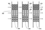
Translated fromKorean도 1은 종래기술로서 Caliper technology의 Bead based microfluidic chip (US6632655)을 도시한 것이다.1 illustrates a beads based microfluidic chip (US6632655) of Caliper technology as a prior art.
도 2는 종래기술로서 IBM의 Micromosaic immunoassays (US 6326058)를 도시한 것이다.2 shows IBM's Micromosaic immunoassays (US 6326058) as prior art.
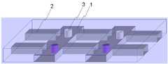
도 3은 본 발명의 일실시예에 따른 미세유체 칩(차단벽 설치전)의 사시도이다.3 is a perspective view of a microfluidic chip (before installation of a barrier wall) according to an embodiment of the present invention.
도 4는 본 발명의 일실시예에 따른 미세유체 칩의 평면도이다.4 is a plan view of a microfluidic chip according to an embodiment of the present invention.
도 5는 본 발명의 일실시예에 따른 미세유체 칩의 평면도이다.5 is a plan view of a microfluidic chip according to an embodiment of the present invention.
도 6은 본 발명의 일실시예에 따른 미세유체 칩의 광중합반응의 모식도이다.6 is a schematic diagram of a photopolymerization reaction of a microfluidic chip according to an embodiment of the present invention.
도 7은 실시예 1에 따른 미세유체 칩에서 프로브 고정화 영역을 광중합하는 것을 나타낸 모식도이다.FIG. 7 is a schematic diagram showing photopolymerization of a probe immobilization region in the microfluidic chip according to Example 1. FIG.
도 8은 실시예 1에 따른 미세유체 칩에서 차단벽을 광중합하는 것을 나타낸 모식도이다.FIG. 8 is a schematic diagram showing photopolymerization of a barrier wall in a microfluidic chip according to Example 1. FIG.
도 9는 실시예 1에 따라 제조된 미세유체 칩의 평면도와 측면도이다.9 is a plan view and a side view of a microfluidic chip manufactured according to Example 1;
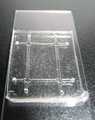
도 10은 실시예 1에 따라 제조된 미세유체 칩의 실제 사진이다.FIG. 10 is an actual photograph of a microfluidic chip manufactured according to Example 1. FIG.
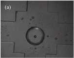
도 11은 Probe 고정화 영역인 GMA gel pad의 현미경 사진들이다.11 are micrographs of a GMA gel pad which is a probe immobilization region.
도 12는 본 발명의 실시예2에 따른 면역어세이(immunoasaay)의 모식도이다.12 is a schematic diagram of an immunoassay (immunoasaay) according to Example 2 of the present invention.
도 13는 도 12의 면역어세이(immunoasaay) 결과인 현미경 사진들이다.FIG. 13 shows micrographs of the immunoassay of FIG. 12.
도 14는 프로브 고정화 영역의 높이 조절 전후의 형광 현미경 사진이다.14 is a fluorescence micrograph before and after height adjustment of the probe immobilization region.
도 15는 Pressure를 이용한 프로브 고정화 영역의 높이 조절 방법의 모식도이다.It is a schematic diagram of the height adjustment method of the probe fixation area | region using Pressure.
도 16은 Partially polymerization을 이용한 프로브 고정화 영역의 높이 조절 방법의 모식도이다.16 is a schematic diagram of a height adjustment method of the probe immobilization region using Partially polymerization.
도 17은 UV 투여량 제어에 의한 부분 중합을 통해 폴리머의 높낮이의 조절이 가능함을 보여주는 사진이다17 is a photograph showing that the height of the polymer can be controlled through partial polymerization by UV dose control.
도 18은 단일층 미세유채 채널내 프로브의 주입방법들을 보여주는 도면들이다.18 is a view showing a method of implanting a probe in a single layer micro rapeseed channel.
본 발명은 미세유체 칩(microfluidic chip)에 관한 것으로서, 더욱 구체적으로 복수의 미세유체 채널(microfluidic channels)을 갖는 다중 바이오어세이(multiple bioassay)용 미세유체 칩(microfluidic chip) 및 그 제조방법에 관한 것이다.The present invention relates to a microfluidic chip, and more particularly, to a microfluidic chip for multiple bioassay having a plurality of microfluidic channels and a method of manufacturing the same. will be.
바이오칩(bio chip)이란 기질상에 분석하고자 하는 DNA, 단백질 등의 생분자 (biomolecules) 프로브를 고밀도로 부착시킨 칩으로서, 상기 프로브와 샘플내 표적물질과의 혼성화(hybridization) 여부를 검출하여 유전자 발현 양상, 유전자 결함, 단백질 분포, 반응 양상 등을 분석해낼 수 있다. 바이오칩은 프로브의 종류에 따라 DNA 칩이나 단백질칩 등으로 나누고, 프로브의 부착형태에 따라 고체 기질상에 부착된 마이크로어레이 칩(microarray chip)과 미세유체 채널상에 부착된 미세유체 칩(microfluidic chip)으로 나눌 수 있다.A bio chip is a chip in which biomolecules probes, such as DNA and protein, to be analyzed are attached on a substrate at high density, and are detected by hybridization between the probe and a target material in a sample. Analyze aspects, gene defects, protein distribution, response patterns, and more. Biochips are divided into DNA chips or protein chips according to the type of probe, and microarray chips attached to solid substrates and microfluidic chips attached to microfluidic channels according to the attachment type of the probe. Can be divided into
미세유체 칩(microfluidic chip)은 샘플 주입, 혼성화 반응과 검출 등 실험의 전 과정을 하나의 작은 칩으로 자동적으로 처리하려는 것으로 랩온어칩(lab-a-chip)이라고도 불리며, 앞으로 실험실에서 플라스크와 실험관을 사라지게 할 획기적인 첨단기술 제품이다. 이 미세유체 칩은 유리, 석영, 플라스틱 또는 실리콘 등의 다양한 재료로 되어 있으며, 칩 내부에 머리카락보다 좁은 복수의 미세 채널이 엇갈려 있다. 이러한 미세 채널을 통해 유체를 흘려보내는 방식으로 여러 가지 복잡한 실험을 한꺼번에 수행할 수 있다.Microfluidic chips are called lab-a-chips that automatically process the entire process of an experiment, such as sample injection, hybridization and detection, into a single chip. It is a breakthrough high-tech product that will make you disappear. The microfluidic chip is made of various materials such as glass, quartz, plastic, or silicon, and a plurality of microchannels narrower than the hair are staggered inside the chip. Many complex experiments can be performed at once by flowing fluid through these microchannels.
Microfluidics channel을 이용한 bioassay platform은 high speed, low cost, multiple test를 할 수 있다는 장점이 있으나 Cross-contamination의 염려가 있으며, 유체 채널제작과 고정화 방법의 공정상 문제가 존재한다. 이러한 공정상의 문제를 해결하기 위해, 종래에는 기판위에 probe 고정화 후 제작된 채널을 접합하는 방법(Array based microfluidc chip)을 사용하였는데, 이는 채널과 고정화된 probe 의 align 문제, 채널 접합시 고열로 인한 프로브 손상 가능성 문제, 고정화된 기판과 제작된 채널의 접합 공정상의 문제가 남아 있다. 이와 달 리 도 1과 같이 채널 제작 후 probe 고정화된 bead를 packing 하는 방법(Bead based microfluidic chip, US6632655)도 사용하고 있는데, 이는 Pressure drop 발생하고, Signal loss와 Sample loss가 생기는 문제가 남아 있다.Bioassay platform using microfluidics channel has the advantages of high speed, low cost, and multiple test, but there is concern about cross-contamination, and there are problems in the process of fluid channel manufacturing and immobilization method. In order to solve this process problem, conventionally, an array based microfluidc chip is used to bond the fabricated channel on the substrate after the probe is immobilized. Problems of damage and problems in the bonding process between the immobilized substrate and the fabricated channel remain. On the other hand, as shown in FIG. 1, a method of packing a probe-immobilized bead after fabricating a channel (Bead based microfluidic chip, US6632655) is also used, which causes pressure drop, signal loss, and sample loss.
또한, 도 2와 같이 복수개의 패터닝 공간(cavities)을 갖는 PDMS 채널 구조체로 기판을 패터닝하여 마이크로모자익 면역어세이(Micromosaic immunoassays, US 6326058)도 개발되었는데, 이는 PDMS 채널 구조체의 방향을 90씩 회전하면서 고정화와 샘플 주입을 함으로써 immunoassay 구현하기 때문에, PDMS 채널 구조체와 glass slide 간의 결합이 reversible하고, mold의 교체가 필요하며, Glass slide 표면이 처리된 이후에는 PDMS와 glass 간에 완벽한 접착이 불가능하므로 용액의 누수가 발생할 염려가 있다.In addition, micromosaic immunoassays (US 6326058) have been developed by patterning a substrate with a PDMS channel structure having a plurality of patterning cavities as shown in FIG. 2, which rotates the PDMS channel structure by 90 degrees. Immunization is achieved by immobilization and sample injection, so the coupling between the PDMS channel structure and the glass slide is reversible, the mold needs to be replaced, and after the glass slide surface has been treated, perfect adhesion between the PDMS and glass is not possible. There is a risk of occurrence.
이에, 본 발명자들은 상기 종래기술들의 문제점들을 극복하기 위하여 예의 연구노력한 결과, 미세유체 채널내에 폴리머로 프로브를 고정화하고 샘플 혼합 방지용 차단벽을 이용하는 경우, 단일층 채널 구조체만을 이용하여 복수 샘플에 대해 다중 바이오어세이 할 수 있음을 확인하고, 본 발명을 완성하게 되었다.Accordingly, the present inventors have diligently researched to overcome the problems of the prior arts. As a result, when the immobilized probe with a polymer in a microfluidic channel and a barrier for preventing sample mixing are used, the present inventors use only a single layer channel structure to multiply multiple samples. After confirming that bioassay is possible, the present invention was completed.
따라서, 본 발명의 주된 목적은 종래의 문제점을 극복할 수 있는 효과적인 다중 바이오어세이용 미세유체 칩의 제조방법을 제공하는 데 있다.Therefore, the main object of the present invention is to provide an effective method for manufacturing a microfluidic chip for multiple bioassays that can overcome the conventional problems.
본 발명의 다른 목적은 상기 제조방법에 의해 제조되는 다중 바이오어세이용 미세유체 칩을 제공하는데 있다.Another object of the present invention is to provide a microfluidic chip for multiple bioassays prepared by the manufacturing method.
본 발명의 목적을 달성하기 위하여, 본 발명은 밑면에 복수의 샘플 채널과 프로브 채널을 위한 오목부를 갖는 채널 구조체를 기판위에 접합하여 미세유체 채널(microfluidic channels)을 제작하는 단계, 상기 프로브 채널 내의 샘플 채널과의 교차점에 프로브 고정화 영역을 제작하는 단계, 상기 프로브 고정화 영역의 프로브 채널 앞뒤에 표적 샘플 간의 혼합 방지용 차단벽(blocking wall)을 제작하는 단계를 포함하는 다중 바이오어세이(multiple bioassay)용 미세유체 칩(microfluidic chip)의 제조방법을 제공한다.In order to achieve the object of the present invention, the present invention comprises the steps of bonding a channel structure having a plurality of sample channels and recesses for the probe channel on the substrate to produce a microfluidic channel, the sample in the probe channel Producing a probe immobilization region at the intersection with the channel, and preparing a blocking wall for preventing mixing between target samples before and after the probe channel of the probe immobilization region, the microorganism for multiple bioassay (multiple bioassay) Provided is a method of manufacturing a microfluidic chip.
본 발명의 제조방법에 있어서, 상기 프로브는 표적 샘플과 혼성화를 필요로 하는 어떤 바이오 물질도 가능하나, 바람직하게는 DNA, RNA, PNA(Peptide Nucleic Acid), LNA(Locked Nucleic Acid), 펩타이드 및 단백질로 구성된 군에서 선택된 바이오 분자인 것을 특징으로 한다. 이러한 바이오 물질은 상기 프로브 고정화 영역에 고정화(immobilization)된다.In the preparation method of the present invention, the probe may be any biomaterial requiring hybridization with a target sample, but preferably DNA, RNA, Peptide Nucleic Acid (PNA), Locked Nucleic Acid (LNA), peptide and protein. It is characterized in that the biomolecule selected from the group consisting of. This biomaterial is immobilized in the probe immobilization region.
본 발명의 제조방법에 있어서, 상기 프로브 고정화 영역은 미세유체 채널 제작 후 형성할 수 있으며 프로브인 바이오 분자 결합기를 가질 수 있는 어떤 고정화 영역도 가능하나, 바람직하게는 바이오분자 결합기를 갖는 폴리머의 광 중합(photo-initiated polymerization)에 의해 제작되는 것을 특징으로 한다. 이러한 광 중합 폴리머는 광개시제(photoinitiator)에 도움으로 포토마스크(photo-mask)를 통해 선택적 영역만 UV에 의해 중합반응된다.In the manufacturing method of the present invention, the probe immobilization region may be formed after fabrication of the microfluidic channel and may be any immobilization region which may have a biomolecule bonding group as a probe, but preferably photopolymerization of a polymer having a biomolecule bonding group. It is characterized in that produced by (photo-initiated polymerization). Such photopolymerized polymers are polymerized by UV only with selective regions through a photo-mask with the help of a photoinitiator.
본 발명의 제조방법에 있어서, 상기 바이오분자 결합기를 갖는 폴리머는 예컨대 에폭시기, 아민기 등과 같은 바이오분자 결합기를 가지고 단량체가 아크릴아 미드, 메타크릴아미드, 아크릴산, 메타크릴산, 또는 이들과 구조적으로 연관된 아미드나 에스테르로 구성된 폴리머와 같이 UV 조사에 의해 광중합될 수 있는 어떤 폴리머도 가능하나, 바람직하게는 글리시딜 메타크릴레이트(GMA) 중합체인 것을 특징으로 한다. 상기 GMA는 광중합에 의해 에폭사이드-활성화된 젤 패드(epoxide-activated gel pad)를 생성한다.In the preparation method of the present invention, the polymer having a biomolecule bonding group has a biomolecule bonding group such as, for example, an epoxy group, an amine group, and the like, and the monomer is structurally associated with acrylamide, methacrylamide, acrylic acid, methacrylic acid, or these. Any polymer that can be photopolymerized by UV irradiation, such as a polymer composed of amides or esters, is possible, but is preferably characterized as a glycidyl methacrylate (GMA) polymer. The GMA produces an epoxide-activated gel pad by photopolymerization.
본 발명의 제조방법에 있어서, 상기 차단벽은 미세유체 채널 제작 후 형성할 수 있으며 프로브인 바이오 분자 결합기를 가지고 있지 않은 어떤 차단벽도 가능하나, 바람직하게는 바이오분자 결합기가 없는 폴리머의 광 중합(photo-initiated polymerization)에 의해 제작되는 것을 특징으로 한다. 이러한 광 중합 폴리머는 광개시제(photoinitiator)에 도움으로 포토마스크(photo-mask)를 통해 패터닝되는 UV에 의해 중합반응된다.In the manufacturing method of the present invention, the barrier wall may be formed after fabrication of the microfluidic channel and may be any barrier wall without a biomolecule bonder as a probe, but is preferably a photopolymerization of a polymer without the biomolecule bonder. -initiated polymerization). Such photopolymerized polymers are polymerized by UV patterning through a photo-mask with the aid of a photoinitiator.
본 발명의 제조방법에 있어서, 상기 바이오분자 결합기를 갖지 않는 폴리머는 예컨대 단량체가 아크릴아미드, 메타크릴아미드, 아크릴산, 메타크릴산, 또는 이들과 구조적으로 연관된 아미드나 에스테르로 구성된 폴리머와 같이 UV 조사에 의해 광중합될 수 있는 어떤 폴리머도 가능하나, 바람직하게는 상기 폴리머는 폴리에틸렌글리콜 디아크릴레이트(PEG-DA) 중합체인 것을 특징으로 한다. 상기 PEG-DA는 표면에 에폭사이드와 같은 바이오분자 결합기가 없으며 따라서 프로브 고정화 영역이외에 프로브가 오염되는 것을 방지할 수 있다.In the production method of the present invention, the polymer having no biomolecule bonding group is subjected to UV irradiation, such as a polymer whose monomer is composed of acrylamide, methacrylamide, acrylic acid, methacrylic acid, or amides or esters structurally associated with them. Any polymer that can be photopolymerized by any one is possible, but preferably the polymer is characterized in that the polyethylene glycol diacrylate (PEG-DA) polymer. The PEG-DA does not have a biomolecule bonding group such as epoxide on the surface and thus can prevent contamination of the probe other than the probe immobilization region.
본 발명의 제조방법에 있어서, 상기 채널 구조체는 기판 위를 덮는 상판으로서 기판과 접합하여 내부에 미세유체 채널을 형성한다. 그 재료로서는 바람직하게 는 유리, PDMS, 또는 폴리머로 된 것을 특징으로 한다. 상기 채널 구조체는 복수의 샘플 채널과 프로브 채널을 가지고 있는 단일 층(single layer)으로서, 종래와 달리 프로브 채널과 샘플 채널용의 구조체를 교체할 필요가 없다.In the manufacturing method of the present invention, the channel structure is a top plate covering the substrate and bonded to the substrate to form a microfluidic channel therein. The material is preferably made of glass, PDMS or polymer. The channel structure is a single layer having a plurality of sample channels and probe channels, and unlike the related art, it is not necessary to replace the structures for the probe channel and the sample channel.
본 발명의 제조방법에 있어서, 상기 기판은 프로브 고정화 영역이 위치하는 하판으로서 채널 구조체와 접합하여 위에 미세유체 채널을 형성한다. 그 재료로서는 바람직하게는 유리, 석영, 플라스틱, 또는 실리콘으로 된 것을 특징으로 한다. 기판은 미세유체 채널 형성후 프로브 고정화 영역이나 차단벽과의 원활한 결합을 위해 표면이 변형될 수 있다.In the manufacturing method of the present invention, the substrate is a lower plate on which the probe immobilization region is located and is bonded to the channel structure to form a microfluidic channel thereon. The material is preferably made of glass, quartz, plastic, or silicon. After forming the microfluidic channel, the substrate may have a modified surface for smooth coupling with the probe immobilization region or the blocking wall.
본 발명의 제조방법에 있어서, 바람직하게는 상기 프로브 고정화 영역은 그 높이가 미세유체 채널의 천장에 못미치게 하는 것을 특징으로 한다. 상기 프로브 고정화 영역이 천장으로부터 떨어져 있으면 그만큼 프로브가 결합할 수 있는 표면적이 증가하여 표적 샘플과의 결합 신호를 증폭시킬 수 있다.In the production method of the present invention, preferably, the probe immobilization area is less than the height of the ceiling of the microfluidic channel. When the probe immobilization region is separated from the ceiling, the surface area to which the probe can bind increases to amplify the binding signal with the target sample.
본 발명의 제조방법에 있어서, 상기 프로브 고정화 영역의 폴리머의 광중합시 채널 구조체에 압력을 가하고 중합이 끝난후에 압력을 제거하는 것에 의해 그 높이가 미세유체 채널의 천장에 못미치게 하는 것을 특징으로 한다. 압력을 가하고 천장까지 중합하더라도 압력을 제거하면 들뜨게 되고 이후 차단벽을 광중합함으로써 그 간격을 더 띄울 수 있다.In the manufacturing method of the present invention, the height is less than the ceiling of the microfluidic channel by applying pressure to the channel structure during photopolymerization of the polymer in the probe immobilization region and removing the pressure after the polymerization is completed. Even if the pressure is applied and polymerized to the ceiling, the pressure is released, and then the gap can be further increased by photopolymerizing the barrier wall.
본 발명의 제조방법에 있어서, 상기 프로브 고정화 영역의 폴리머 광중합시 UV 투여량 제어(dose control)에 의해 부분 중합(partially polymerization)함으로써 그 높이가 미세유체 채널의 천장에 못미치게 하는 것을 특징으로 한다. 천장까 지 광중합하는 UV 투여량을 측정한 후 그보다 적은 투여량으로 부분 중합한다.In the manufacturing method of the present invention, the polymer is partially polymerized by UV dose control during photopolymerization of the probe immobilization region so that the height thereof is less than the ceiling of the microfluidic channel. UV doses that photopolymerize to the ceiling are measured and then partially polymerized at lower doses.
본 발명의 다른 목적을 달성하기 위해, 본 발명은 기판, 그 위에 접합된 단일층 채널 구조체, 채널 구조체내에 형성된 복수의 샘플 채널과 프로브 채널, 상기 프로브 채널과 샘플 채널의 교차점에 형성된 프로브 고정화 영역, 상기 프로브 고정화 영역의 프로브 채널 앞뒤에 형성된 표적 샘플 간의 혼합 방지용 차단벽(blocking wall)을 포함하는 다중 바이오어세이(multiple bioassay)용 미세유체 칩(microfluidic chip)을 제공한다.In order to achieve another object of the present invention, the present invention provides a substrate, a monolayer channel structure bonded thereon, a plurality of sample channels and probe channels formed in the channel structure, a probe immobilization region formed at the intersection of the probe channel and the sample channel, Provided is a microfluidic chip for multiple bioassay including a blocking wall for preventing mixing between target samples formed before and after the probe channel of the probe immobilization region.
이하, 첨부 도면을 참조하여 본 발명을 상세히 설명한다.Hereinafter, the present invention will be described in detail with reference to the accompanying drawings.
도 3a은 본 발명의 일실시예에 따른 미세유체 칩(차단벽 설치전)의 사시도이다. 기판과 접합한 단일층의 채널 구조체내에 두개의 샘플 채널(1)과 두개의 프로브 채널(2)가 서로 교차하고 있으며, 교차점에 프로브 고정화 영역(3)이 형성되어 있다.3A is a perspective view of a microfluidic chip (before installation of a blocking wall) according to an embodiment of the present invention. Two
도 3b는 본 발명의 일실시예에 따른 미세유체 칩(차단벽 설치후)의 사시도이다. 기판과 접합한 단일층의 채널 구조체내에 두개의 샘플 채널(1)과 두개의 프로브 채널(2)가 서로 교차하고 있으며, 교차점에 프로브 고정화 영역(3)이 형성되어 있으며, 프로브 고정화 영역의 양옆에 한쌍의 차단벽(4,4')이 형성되어 있다.3B is a perspective view of a microfluidic chip (after installing a blocking wall) according to an embodiment of the present invention. Two
도 4는 본 발명의 일실시예에 따른 미세유체 칩의 평면도이다. 두개의 샘플 채널(1)과 두개의 프로브 채널(2)가 서로 교차하고 있으며, 교차점에 프로브 고정화 영역(3)이 형성되어 있으며, 프로브 고정화 영역의 양옆에 한쌍의 차단벽(4,4')이 형성되어 있다. 상기 두개의 샘플 채널을 통해 샘플1과 샘플2가 각각 주입된다. 이때 차단벽(4,4')은 샘플이 서로 혼합되는 것을 방지한다.4 is a plan view of a microfluidic chip according to an embodiment of the present invention. Two
도 5는 본 발명의 일실시예에 따른 미세유체 칩의 평면도이다. 5개의 샘플 채널과 4개의 프로브 채널가 서로 교차하고 있으며, 교차점에 프로브 고정화 영역이 형성되어 있다. 상기 4개의 프로브 채널을 통해 서로 다른 프로브 1 내지 4가 각각 주입되며, 상기 5개의 샘플 채널을 통해 서로 다른 샘플 1 내지 5가 각각 주입된다. 프로브 채널과 샘플 채널의 개수는 필요에 따라 선택할 수 있으며, 따라서, 복수의 샘플에 대한 다중 바이오어세이(multiple bioassay)가 가능하다.5 is a plan view of a microfluidic chip according to an embodiment of the present invention. Five sample channels and four probe channels intersect each other, and a probe immobilization region is formed at the intersection.
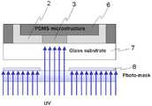
도 6은 본 발명의 일실시예에 따른 미세유체 칩의 광중합반응의 모식도이다. 기판(7)위에 접합된 채널 구조체(6)를 프로브 채널(2) 방향으로 단면도를 나타낸 것으로서, 프로브 고정화 영역(3)을 형성하기 위해 바이오분자 결합기를 갖는 폴리머를 광개시제(photoinitiator)에 도움으로 포토마스크(8)를 통해 패터닝되는 UV에 의해 광 중합(photopolymerization)반응한다. 이러한 광중합반응은 차단벽(미도시)을 형성하는데도 사용될 수 있다. 차단벽을 형성하기 위해 바이오분자 결합기를 갖지 않는 폴리머를 광개시제(photoinitiator)에 도움으로 포토마스크(8)를 통해 패터닝되는 UV에 의해 광 중합(photopolymerization)반응한다. 구체적인 일례로서, 프로브 고정화 영역을 형성하기 위해 glycidyl methacrylate (GMA)와 photoinitiator (HOMPP)를 사용하여 epoxide-activated gel pad를 생성할 수 있으며 (Hermanson G T 1996 Bioconjugate Techniques 참조), 차단벽을 형성하기 위해PEG-DA(poly(ethylene glycol) diacrylate)와 photoinitiator (HOMPP)를 사용하여 바이오분자 결합기가 없는 폴리머를 생성할 수 있다.6 is a schematic diagram of a photopolymerization reaction of a microfluidic chip according to an embodiment of the present invention. A cross-sectional view of the
이하, 실시예를 통하여 본 발명을 더욱 상세히 설명하기로 한다. 이들 실시예는 단지 본 발명을 예시하기 위한 것이므로, 본 발명의 범위가 이들 실시예에 의해 제한되는 것으로 해석되지는 않는다.Hereinafter, the present invention will be described in more detail with reference to Examples. Since these examples are only for illustrating the present invention, the scope of the present invention is not to be construed as being limited by these examples.
실시예 1: 미세유체 칩의 제작Example 1 Fabrication of Microfluidic Chips
SU-8 (Microchem사)을 실리콘 기판위에 spin coating한 후, 포토리소그래피 방법으로 패턴을 형성하여 미세유체 구조체를 만들기 위한 mold로 사용하고, 이 몰드(mold)위에 PDMS prepolymer mixture (Sigard184, Dowcorning사)를 붓고 80도의 온도에서 경화를 시킨후 mold가 있는 기판에서 떼어내 PDMS 구조체를 만든다. 위에서 만든 PDMS 구조체를 O2 플라즈마 처리한 후 하판으로 사용할 glass 기판과 접합한다(50-80도 열처리). 이상과 같이 제작한 미세채널구조체 내에서 폴리머와 기판의 공유결합을 돕기 위해 프로브 채널을 따라 TPM surface modification하고 (3-(trichlorosilyl) propyl methacrylate (TPM) 는 unmodified glass를 acrylate-activated form으로 바꾸어GMA gel pad와glass 사이에 접합력이 증가하게하는 역할을 함), probe 고정화 영역을 define하기 위해 (GMA gel pad 단량체와 photoinitiator(HOMPP)의 부피비를 99:1로하여, 상기 제작된 채널내에 채운 후, 제작된 photomask를 통하여 UV를 노광 하고, pH 9.5인 carbonate를 수분 동안 흘려 광중합되지 않은 단량체를 세척하여) GMA photopolymerization하고, Probe로서 protein을 고정화하고 원하는 단백질(FITC가 레이블된 anti-human IgG)을 100㎍/L 농도로 하여 상기제작된 채널내에 채운 후 20분동안 상온에서 반등 시킨 후, PBST 용액을 분당 0.2ml의 유량으로 20분동안 흘려줌으로써 세척한다. blocking wall을 define하기 위해 PEG-DA photopolymerizatin하였다. 단량체만 PEGDA인 점을 제외하고, GMA pad 형성방법과 동일한 방법을 사용하였다.After spin coating SU-8 (Microchem) on a silicon substrate, it is used as a mold to form a microfluidic structure by forming a pattern by a photolithography method, and a PDMS prepolymer mixture (Sigard184, Dowcorning) on this mold Pour and cure at 80 degrees and remove from the substrate with mold to make PDMS structure. The PDMS structure made above is subjected to O2 plasma treatment and then bonded to a glass substrate to be used as a bottom plate (50-80 degree heat treatment). In order to help covalent bonding of polymer and substrate in the microchannel structure fabricated as described above, TPM surface modification was carried out along the probe channel and (3- (trichlorosilyl) propyl methacrylate (TPM) changed GMO gel by converting unmodified glass into acrylate-activated form. To increase the bonding force between the pad and the glass), to define the probe immobilization area (volume ratio of GMA gel pad monomer and photoinitiator (HOMPP) to 99: 1, filled in the prepared channel, and then fabricated Exposing UV through a photomask, washing the unpolymerized monomer by flowing carbonate pH 9.5 for several minutes), GMA photopolymerization, immobilizing the protein as a probe, and 100 ㎍ of the desired protein (FITC-labeled anti-human IgG). After filling into the prepared channel at / L concentration and rebounding at room temperature for 20 minutes, the PBST solution is washed by flowing for 20 minutes at a flow rate of 0.2 ml per minute. PEG-DA photopolymerizatin was used to define the blocking wall. The same method as the GMA pad formation method was used except that only monomer was PEGDA.
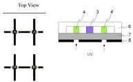
도 7은 실시예 1에 따른 미세유체 칩에서 프로브 고정화 영역을 광중합하는 것을 나타낸 모식도이다. GMA에 포토마스크(8)를 통해 UV를 조사하여 프로브 고정화 영역(3)을 광중합시킨다. 도 8은 실시예 1에 따른 미세유체 칩에서 차단벽을 광중합하는 것을 나타낸 모식도이다. PEG-DA에 포토마스크(8)를 통해 UV를 조사하여 차단벽(4,4')을 광중합시킨다. 도 9는 실시예 1에 따라 제조된 미세유체 칩의 평면도와 측면도이다. 평면도에서 두개의 샘플 채널과 두개의 프로브 채널이 교차되고 있으며, 측면도는 프로브 채널방향의 단면을 나타내는 것으로 교차점마다 한개씩 두개의 프로브 고정화 영역(3)이 있다. 도 10은 실시예 1에 따라 제조된 미세유체 칩의 실제 사진이다. 도 11은 Probe 고정화 영역인 GMA gel pad의 현미경 사진들이다. 도 11a는 광학 현미경 사진(optical photograph)이고, 도 11b는 도 11a의 형광 현미경 사진(fluorescence photograph)이다. GMA 구조에 고정화된 FITC로 라벨된 anti-human IgG의 Fluorescence image를 CCD camera의 FITC filter를 사용하여 얻었다. GMA gel pad의 반경은 약 1000 ㎛ 이었다.FIG. 7 is a schematic diagram showing photopolymerization of a probe immobilization region in the microfluidic chip according to Example 1. FIG. The GMA is irradiated with UV through a
실시예 2 : 면역어세이(Immunoassay)Example 2 Immunoassay
실시예 1에서 제조된 미세유체 칩을 사용하여 GMA gel pad 상에서 specific immunoreaction을 하였다. 실시예1의 GMA gel pad 형성 후 gel pad에 probe 단백질로 사용하고자 0.1g/L human IgG and mouse IgG를 각각 한 채널씩 채운 후 실시예1의 방법과 동일하게 고정화하였고, 차단벽 또한 동일한 방법으로 제작 한 후, 프로브 단백질과 immunoraction을 100㎍/L 의 농도로 FITC 레이블된 anti-human IgG 와 anti-mouse IgG를 수직방향의 채널에 각각 채운후 상온에서 20분간 반응을 실시한 후 실시예1과 동일한 방법으로 세척하였다.The microfluidic chip prepared in Example 1 was used for specific immunoreaction on GMA gel pad. After the GMA gel pad was formed in Example 1, 0.1 g / L human IgG and mouse IgG were filled with one channel to be used as a probe protein on the gel pad, and then immobilized in the same manner as in Example 1, and the barrier wall was also fixed in the same manner. After the preparation, the probe protein and immunoraction were filled with FITC-labeled anti-human IgG and anti-mouse IgG in a vertical channel at a concentration of 100 µg / L, and then reacted at room temperature for 20 minutes. Washed by the method.
도 12는 본 발명의 실시예2에 따른 면역어세이(immunoasaay)의 모식도이다. 1, 2, 3, 4는 교차점마다의 프로브 고정화 영역으로서, 거기에 고정화되는 프로브(capture protein)과 이와 반응하는 표적 샘플(target protein)의 종류는 아래 표 1과 같다.12 is a schematic diagram of an immunoassay (immunoasaay) according to Example 2 of the present invention. 1, 2, 3, and 4 are probe immobilization regions for each crossing point, and the types of probes immobilized thereon and the types of target proteins reacting with them are shown in Table 1 below.
[표 1]TABLE 1

실험결과, 도 13에서 보여지듯이, 1, 4번 gel은 match(형광신호 유)되었고, 2, 3번 gel은 unmatch(형광신호 무)되어서, 본 발명의 미세유체 칩에 따르면 프로브나 샘플의 상호 오염없이 정확히 면역어세이가 가능함을 알 수 있었다.As shown in FIG. 13,
실시예 3 : 프로브 고정화 영역의 높이 조절Example 3 Adjusting the Height of the Probe Immobilization Region
실시예 1의 미세유체 칩의 제조방법을 변형하여, 프로브 고정화 영역의 높이를 미세유체 채널의 천장에 못미치게 만들 수 있다. 프로브 고정화 영역이 천장으 로부터 떨어져 있으면 그만큼 프로브가 결합할 수 있는 표면적이 증가하여 표적 샘플과의 결합 신호를 증폭시킬 수 있다. 도 14의 왼쪽은 프로브 고정화 영역이 천장까지 닿은 경우의 현광 현미경 사진으로서 기둥의 측면에만 프로브가 결합하여 형광신호가 원형 고리형태로 나타나나, 오른쪽은 프로브 고정화 영역이 천장에서 떨어진 경우의 현광 현미경 사진으로서 기둥의 측면 뿐만아니라 기둥의 상면에도 프로브가 결합하여 형광신호가 꽉찬 원형으로 나타난다.By modifying the manufacturing method of the microfluidic chip of Example 1, the height of the probe immobilization region can be made less than the ceiling of the microfluidic channel. If the probe immobilization region is away from the ceiling, the surface area to which the probe can bind increases the amplification of the binding signal with the target sample. The left side of FIG. 14 is a fluorescence micrograph when the probe immobilization region reaches the ceiling, and the probe is coupled to only the side surface of the column, so that the fluorescent signal appears in the form of a circular ring. The right side is the fluorescence micrograph when the probe immobilization region is separated from the ceiling. As a result, the probe is coupled not only to the side of the column but also to the top of the column, so that the fluorescent signal appears as a full circle.
이렇게 프로브 고정화 영역의 높이를 조절하기 위한 한가지 방법은 Pressure를 이용하는 것이다. 도 15에서 보여지듯이, 프로브 고정화 영역의 폴리머의 광중합시 채널 구조체에 압력을 가하고 중합이 끝난후에 압력을 제거한 후 차단벽을 광중합함으로써 프로브 고정화 영역의 높이가 미세유체 채널의 천장에 못미치게 할 수 있다One way to adjust the height of the probe immobilization region is to use pressure. As shown in FIG. 15, the height of the probe immobilization region can be less than the ceiling of the microfluidic channel by applying pressure to the channel structure during photopolymerization of the polymer in the probe immobilization region, removing the pressure after the polymerization is completed, and photopolymerizing the barrier wall.
또 다른 방법은 Partially polymerization을 이용하는 것이다. 도 16에서 보여지듯이, 프로브 고정화 영역의 폴리머 광중합시 UV 투여량 제어(dose control)에 의해 부분 중합(partially polymerization)함으로써 그 높이가 미세유체 채널의 천장에 못미치게 할 수 있다. 도 17은 UV 투여량 제어에 의한 부분 중합을 통해 폴리머의 높낮이의 조절이 가능함을 보여주는 사진이다(uTAS 2002, JHKim 참조)Another method is to use partial polymerization. As shown in FIG. 16, the polymerization of the probe immobilization region can be partially polymerized by UV dose control, so that its height can be less than the ceiling of the microfluidic channel. FIG. 17 is a photograph showing that the height of the polymer can be controlled through partial polymerization by UV dose control (see
실시예 4 : 단일층 미세유체 채널내 프로브의 주입Example 4 Injection of Probes into Single Layer Microfluidic Channels
단일층 미세유채 채널에서는 프로브 채널과 샘플 채널이 서로 교차로 연결되어 있기 때문에 샘플뿐만 아니라 프로브간에도 서로 혼합되어 오염될 수 있다. 따라서, 프로브 주입시 서로다른 프로브 채널간의 프로브 혼합을 방지하기 위해 3가 지 방법을 사용할 수 있다.In the single layer micro rapeseed channel, since the probe channel and the sample channel are cross-connected with each other, they may be mixed and contaminated between the probe as well as the sample. Thus, three methods can be used to prevent probe mixing between different probe channels during probe injection.
첫 번째 방법은 도 18a와 같이, 서로 다른 프로브 채널의 주입구에 동일 압력으로 동시에 프로브들을 흘려보내면서 반대편 프로브 채널의 출구들만 오픈하고 다른 입출구를 모두 폐쇄하는 것이다(O는 오픈, X는 폐쇄). 그러면, 한 프로브의 흐름이 동일한 압력의 다른 프로브의 흐름으로 이동하지 못하고 압력이 약한 자신의 출구쪽으로만 흐름이 유지될 수 있다.The first method is to open only the outlets of the opposite probe channel and close all other inlets and outlets (O is open, X is closed) while simultaneously sending the probes to the inlets of different probe channels at the same pressure as shown in FIG. 18A. Then, the flow of one probe may not move to the flow of another probe of the same pressure, and the flow may be maintained only toward its outlet where the pressure is weak.
두 번째 방법은 도 18b와 같이, 서로 다른 프로브 채널의 주입구에 순차적으로 프로브를 흘려보내면서, 자기 자신의 프로브 채널의 반대편 출구만을 오픈시키고, 다른 입출구를 모두 폐쇄하는 것이다(O는 오픈, X는 폐쇄). 그러면 프로브의 흐름은 유일한 출구인 자신의 반대편 출구로만 흐름이 유지된다. 도 18b의 1)에서는 우선 프로브 A(Capture A)만을 흘려보내고 다음에 프로브 B(Capture B)만을 흘려보낸다.The second method is to flow the probes sequentially through the inlets of the different probe channels as shown in FIG. 18B, opening only the opposite outlets of the own probe channels and closing all other inlets and outlets (O is open, X is Closure). The flow of the probe is then maintained only at its opposite outlet, the only outlet. In FIG. 18B 1), only probe A (Capture A) is first flowed and only probe B (Capture B) is flowed first.
마지막 방법은 도 18c와 같이 프로브를 흘려보내기 전에 교차점의 샘플채널 위 아래에 프로브 차단벽을 설치하는 것이다. 상기 프로브 차단벽의 재료로는 pH나 온도에 따라 부피가 변화하여 개폐가능한 하이드로젤(hydrogel)이 바람직하다. 상기 하이드로젤은 에틸렌기를 갖는 단량체 단위가 광중합 반응하여 제조될 수 있다. 단량체가 아크릴아미드, 메타크릴아미드, 아크릴산, 메타크릴산, 또는 이들과 구조적으로 연관된 아미드나 에스테르로 구성된 폴리머가 사용될 수 있다. 도 18c의 1)에서 프로브 차단벽을 형성하고, 2)에서 서로 다른 프로브들을 프로브 채널을 통해 흘려보내고, 3)에서 프로브 앞뒤에 차단벽(샘플 차단벽)을 형성하고, 4)에서 프로 브 차단벽을 오픈시킨후, 5)에서 샘플 채널을 통해 서로 다른 샘플들을 흘려보낸다.The last method is to install a probe blocking wall above and below the sample channel of the intersection before flowing the probe as shown in FIG. 18C. As the material of the probe blocking wall, a hydrogel that can be opened and closed by changing its volume according to pH or temperature is preferable. The hydrogel may be prepared by photopolymerization of a monomer unit having an ethylene group. Polymers whose monomers consist of acrylamide, methacrylamide, acrylic acid, methacrylic acid, or amides or esters structurally associated with them can be used. In Fig. 18C, the probe blocking wall is formed, the different probes are flowed through the probe channel in 2), the blocking wall (sample blocking wall) is formed before and after the probe in 3), and the probe blocking is performed in 4). After opening the wall, we flow different samples through the sample channel in 5).
이상 설명한 바와 같이, 본 발명에 따르면 미세유체 채널(microfluidic channel) 제작 후 채널 내에서 프로브를 고정화함으로써 종래 기판위에 프로브 고정화 후 유체 채널을 접합시 공정상의 어려움을 해소할 수 있으며, 복수의 샘플을 동시에 로딩할 수 있음으로써 다중 바이오어세이(multiple bioassay)가 가능한 미세유체 플랫폼(microfluidic platform)을 구축할 수 있다. 또한, Single layer microfluidic channel로 제조공정을 단순화할 수 있으며, blocking wall으로 sample 혼합을 방지하고, polymer를 이용하여 probe를 효과적으로 고정화할 수 있다.As described above, according to the present invention, by immobilizing the probe in the channel after fabricating the microfluidic channel, the process difficulty in bonding the fluid channel after immobilizing the probe on the conventional substrate can be solved. By loading, it is possible to build a microfluidic platform capable of multiple bioassays. In addition, a single layer microfluidic channel can simplify the manufacturing process, prevent sample mixing with a blocking wall, and effectively fix the probe using polymers.
Claims (12)
Translated fromKoreanPriority Applications (2)
| Application Number | Priority Date | Filing Date | Title |
|---|---|---|---|
| KR1020050005533AKR100682920B1 (en) | 2005-01-20 | 2005-01-20 | Multi-bioassay microfluidic chip and its manufacturing method |
| US11/335,939US7670772B2 (en) | 2005-01-20 | 2006-01-20 | Microfluidic chip for multiple bioassay and method of manufacturing the same |
Applications Claiming Priority (1)
| Application Number | Priority Date | Filing Date | Title |
|---|---|---|---|
| KR1020050005533AKR100682920B1 (en) | 2005-01-20 | 2005-01-20 | Multi-bioassay microfluidic chip and its manufacturing method |
Publications (2)
| Publication Number | Publication Date |
|---|---|
| KR20060084737A KR20060084737A (en) | 2006-07-25 |
| KR100682920B1true KR100682920B1 (en) | 2007-02-15 |
Family
ID=36913180
Family Applications (1)
| Application Number | Title | Priority Date | Filing Date |
|---|---|---|---|
| KR1020050005533AExpired - Fee RelatedKR100682920B1 (en) | 2005-01-20 | 2005-01-20 | Multi-bioassay microfluidic chip and its manufacturing method |
Country Status (2)
| Country | Link |
|---|---|
| US (1) | US7670772B2 (en) |
| KR (1) | KR100682920B1 (en) |
Cited By (3)
| Publication number | Priority date | Publication date | Assignee | Title |
|---|---|---|---|---|
| KR100930859B1 (en) | 2007-08-22 | 2009-12-10 | 한양대학교 산학협력단 | Micro biochip and its manufacturing method for the simultaneous multi-immune response measurement and a method for detecting the immune response using the same |
| KR100968640B1 (en) | 2007-10-06 | 2010-07-06 | 재단법인서울대학교산학협력재단 | Single Cell Signal Analysis |
| US12241857B2 (en) | 2021-03-16 | 2025-03-04 | Arizona Board Of Regents On Behalf Of Arizona State University | High density and multiplexed nanopore devices with transverse tunneling junction for biomolecule detection and sequencing |
Families Citing this family (18)
| Publication number | Priority date | Publication date | Assignee | Title |
|---|---|---|---|---|
| KR101368178B1 (en) | 2008-01-07 | 2014-02-26 | 삼성전자주식회사 | Method of fomring a filter in a fluid flow path in a microfluidic device |
| CN102056838B (en) | 2008-04-11 | 2013-07-03 | 弗卢丁公司 | Microfluidic devices and methods |
| CA2730480A1 (en)* | 2008-07-15 | 2010-01-21 | L3 Technology Limited | Assay device and methods |
| KR101335725B1 (en)* | 2008-10-02 | 2013-12-04 | 삼성전자주식회사 | Microfluidic structure for multi-assay and microfluidic device comprising same |
| US8058630B2 (en)* | 2009-01-16 | 2011-11-15 | Fluidigm Corporation | Microfluidic devices and methods |
| US20190300945A1 (en) | 2010-04-05 | 2019-10-03 | Prognosys Biosciences, Inc. | Spatially Encoded Biological Assays |
| US10787701B2 (en) | 2010-04-05 | 2020-09-29 | Prognosys Biosciences, Inc. | Spatially encoded biological assays |
| GB201106254D0 (en) | 2011-04-13 | 2011-05-25 | Frisen Jonas | Method and product |
| CN102897707B (en)* | 2011-07-27 | 2015-07-22 | 国家纳米科学中心 | Fluid device for controlling microtubule movement direction, its preparation method and application |
| WO2014060483A1 (en) | 2012-10-17 | 2014-04-24 | Spatial Transcriptomics Ab | Methods and product for optimising localised or spatial detection of gene expression in a tissue sample |
| CN105849275B (en)* | 2013-06-25 | 2020-03-17 | 普罗格诺西斯生物科学公司 | Method and system for detecting spatial distribution of biological targets in a sample |
| CA2982146A1 (en) | 2015-04-10 | 2016-10-13 | Spatial Transcriptomics Ab | Spatially distinguished, multiplex nucleic acid analysis of biological specimens |
| EP3861356A4 (en) | 2018-10-01 | 2022-07-06 | Polyvalor, Limited Partnership | SYSTEM AND PROCEDURE FOR LIQUID DISPENSING |
| US11673362B2 (en) | 2020-01-02 | 2023-06-13 | The Boeing Company | Composite structural panels and methods of forming thereof |
| US12110541B2 (en) | 2020-02-03 | 2024-10-08 | 10X Genomics, Inc. | Methods for preparing high-resolution spatial arrays |
| US12031177B1 (en) | 2020-06-04 | 2024-07-09 | 10X Genomics, Inc. | Methods of enhancing spatial resolution of transcripts |
| CN112619720A (en)* | 2020-12-07 | 2021-04-09 | 厦门大学 | Micro-fluidic chip containing probe array and preparation method thereof |
| CN112570052A (en)* | 2020-12-07 | 2021-03-30 | 厦门大学 | Micro-fluidic device containing probe array and micro-fluidic chip with side channels |
Citations (4)
| Publication number | Priority date | Publication date | Assignee | Title |
|---|---|---|---|---|
| US5942443A (en) | 1996-06-28 | 1999-08-24 | Caliper Technologies Corporation | High throughput screening assay systems in microscale fluidic devices |
| US20030138829A1 (en) | 2001-11-30 | 2003-07-24 | Fluidigm Corp. | Microfluidic device and methods of using same |
| US6709559B2 (en)* | 1997-06-06 | 2004-03-23 | Caliper Technologies Corp. | Microfabricated structures for facilitating fluid introduction into microfluidic devices |
| KR20050055336A (en)* | 2003-12-08 | 2005-06-13 | 한국항공우주연구원 | An insertion type turnbuckle having thread formed on an insertion groove thereof |
Family Cites Families (6)
| Publication number | Priority date | Publication date | Assignee | Title |
|---|---|---|---|---|
| US6406845B1 (en)* | 1997-05-05 | 2002-06-18 | Trustees Of Tuft College | Fiber optic biosensor for selectively detecting oligonucleotide species in a mixed fluid sample |
| US6089853A (en)* | 1997-12-24 | 2000-07-18 | International Business Machines Corporation | Patterning device for patterning a substrate with patterning cavities fed by service cavities |
| US20010006780A1 (en)* | 1998-06-30 | 2001-07-05 | Benjamin W. Boldt | Process for detecting a known sequence in genomic dna |
| US6632655B1 (en)* | 1999-02-23 | 2003-10-14 | Caliper Technologies Corp. | Manipulation of microparticles in microfluidic systems |
| SE9902474D0 (en)* | 1999-06-30 | 1999-06-30 | Amersham Pharm Biotech Ab | Polymer valves |
| AU2002307152A1 (en)* | 2001-04-06 | 2002-10-21 | California Institute Of Technology | Nucleic acid amplification utilizing microfluidic devices |
- 2005
- 2005-01-20KRKR1020050005533Apatent/KR100682920B1/ennot_activeExpired - Fee Related
- 2006
- 2006-01-20USUS11/335,939patent/US7670772B2/ennot_activeExpired - Fee Related
Patent Citations (4)
| Publication number | Priority date | Publication date | Assignee | Title |
|---|---|---|---|---|
| US5942443A (en) | 1996-06-28 | 1999-08-24 | Caliper Technologies Corporation | High throughput screening assay systems in microscale fluidic devices |
| US6709559B2 (en)* | 1997-06-06 | 2004-03-23 | Caliper Technologies Corp. | Microfabricated structures for facilitating fluid introduction into microfluidic devices |
| US20030138829A1 (en) | 2001-11-30 | 2003-07-24 | Fluidigm Corp. | Microfluidic device and methods of using same |
| KR20050055336A (en)* | 2003-12-08 | 2005-06-13 | 한국항공우주연구원 | An insertion type turnbuckle having thread formed on an insertion groove thereof |
Non-Patent Citations (1)
| Title |
|---|
| 1020050005533 - 683513 |
Cited By (3)
| Publication number | Priority date | Publication date | Assignee | Title |
|---|---|---|---|---|
| KR100930859B1 (en) | 2007-08-22 | 2009-12-10 | 한양대학교 산학협력단 | Micro biochip and its manufacturing method for the simultaneous multi-immune response measurement and a method for detecting the immune response using the same |
| KR100968640B1 (en) | 2007-10-06 | 2010-07-06 | 재단법인서울대학교산학협력재단 | Single Cell Signal Analysis |
| US12241857B2 (en) | 2021-03-16 | 2025-03-04 | Arizona Board Of Regents On Behalf Of Arizona State University | High density and multiplexed nanopore devices with transverse tunneling junction for biomolecule detection and sequencing |
Also Published As
| Publication number | Publication date |
|---|---|
| US7670772B2 (en) | 2010-03-02 |
| KR20060084737A (en) | 2006-07-25 |
| US20060188906A1 (en) | 2006-08-24 |
Similar Documents
| Publication | Publication Date | Title |
|---|---|---|
| KR100682920B1 (en) | Multi-bioassay microfluidic chip and its manufacturing method | |
| US9201069B2 (en) | Microfluidic devices and methods including porous polymer monoliths | |
| CA2408692C (en) | Micro-globule metering and sampling structure and microchips having the structure | |
| KR102007715B1 (en) | Encoded polymeric microparticles | |
| JP2003503716A (en) | Polymer valve | |
| Sahin et al. | Flow lithography for structured microparticles: fundamentals, methods and applications | |
| US20100204065A1 (en) | Microarray using laminar flow and method of preparing the same | |
| KR100799267B1 (en) | Micro or nanofluidic chips made by NOA and bioanalytical platforms made using them | |
| WO2007074756A1 (en) | Microchip for immunoassay, kit for immunoassay and immunoassay method | |
| KR101068972B1 (en) | Biomolecule array with improved fluorescence signal and manufacturing method thereof | |
| CN104561286A (en) | Novel polymerase chain reaction (PCR) microfluidic chip control system and preparation method thereof | |
| CN112920951A (en) | Cell screening chip and manufacturing and cell screening and collecting method thereof | |
| WO2025175858A1 (en) | Microfluidic chip manufacturing method | |
| US8741974B2 (en) | Method of forming filter in fluid flow path in microfluidic device | |
| KR20100049880A (en) | Microarray with micro-well pattern and manufacturing method of the same | |
| US20040101439A1 (en) | Biological and chemical reaction devices and methods of manufacture | |
| CN109012773B (en) | Preparation method and functionalization method of micro-fluidic chip for photoinduced infiltration | |
| KR102061191B1 (en) | Microfluidic chip for Multi Immunodiagnosis and Method for manufacturing thereof | |
| KR20180043445A (en) | Modification method for hydrophilic surface on a microstructure in a microchip | |
| KR101151221B1 (en) | The method of manufacturing a structure with micro-channels and the structure using the same | |
| KR101053772B1 (en) | Molding module for manufacturing a microfluidic chip mold, a method for manufacturing a microfluidic chip mold using the same, and a microfluidic chip mold manufactured thereby | |
| US20080199371A1 (en) | Microfluidic Device for Patterned Surface Modification | |
| JP2005274405A (en) | Micro fluid device, and method of introducing micro sample | |
| CN113219164A (en) | Biochip, preparation method thereof and detection device | |
| KR20100025330A (en) | Method for preparing microarrays by using optically transparent array molds with an array of concaves |
Legal Events
| Date | Code | Title | Description |
|---|---|---|---|
| A201 | Request for examination | ||
| PA0109 | Patent application | St.27 status event code:A-0-1-A10-A12-nap-PA0109 | |
| PA0201 | Request for examination | St.27 status event code:A-1-2-D10-D11-exm-PA0201 | |
| R17-X000 | Change to representative recorded | St.27 status event code:A-3-3-R10-R17-oth-X000 | |
| PN2301 | Change of applicant | St.27 status event code:A-3-3-R10-R13-asn-PN2301 St.27 status event code:A-3-3-R10-R11-asn-PN2301 | |
| PN2301 | Change of applicant | St.27 status event code:A-3-3-R10-R13-asn-PN2301 St.27 status event code:A-3-3-R10-R11-asn-PN2301 | |
| D13-X000 | Search requested | St.27 status event code:A-1-2-D10-D13-srh-X000 | |
| D14-X000 | Search report completed | St.27 status event code:A-1-2-D10-D14-srh-X000 | |
| E902 | Notification of reason for refusal | ||
| PE0902 | Notice of grounds for rejection | St.27 status event code:A-1-2-D10-D21-exm-PE0902 | |
| PG1501 | Laying open of application | St.27 status event code:A-1-1-Q10-Q12-nap-PG1501 | |
| E701 | Decision to grant or registration of patent right | ||
| PE0701 | Decision of registration | St.27 status event code:A-1-2-D10-D22-exm-PE0701 | |
| GRNT | Written decision to grant | ||
| PR0701 | Registration of establishment | St.27 status event code:A-2-4-F10-F11-exm-PR0701 | |
| PR1002 | Payment of registration fee | St.27 status event code:A-2-2-U10-U11-oth-PR1002 Fee payment year number:1 | |
| PG1601 | Publication of registration | St.27 status event code:A-4-4-Q10-Q13-nap-PG1601 | |
| PR1001 | Payment of annual fee | St.27 status event code:A-4-4-U10-U11-oth-PR1001 Fee payment year number:4 | |
| PR1001 | Payment of annual fee | St.27 status event code:A-4-4-U10-U11-oth-PR1001 Fee payment year number:5 | |
| PR1001 | Payment of annual fee | St.27 status event code:A-4-4-U10-U11-oth-PR1001 Fee payment year number:6 | |
| R18-X000 | Changes to party contact information recorded | St.27 status event code:A-5-5-R10-R18-oth-X000 | |
| FPAY | Annual fee payment | Payment date:20130115 Year of fee payment:7 | |
| PR1001 | Payment of annual fee | St.27 status event code:A-4-4-U10-U11-oth-PR1001 Fee payment year number:7 | |
| FPAY | Annual fee payment | Payment date:20140124 Year of fee payment:8 | |
| PR1001 | Payment of annual fee | St.27 status event code:A-4-4-U10-U11-oth-PR1001 Fee payment year number:8 | |
| FPAY | Annual fee payment | Payment date:20150116 Year of fee payment:9 | |
| PR1001 | Payment of annual fee | St.27 status event code:A-4-4-U10-U11-oth-PR1001 Fee payment year number:9 | |
| FPAY | Annual fee payment | Payment date:20160118 Year of fee payment:10 | |
| PR1001 | Payment of annual fee | St.27 status event code:A-4-4-U10-U11-oth-PR1001 Fee payment year number:10 | |
| FPAY | Annual fee payment | Payment date:20170117 Year of fee payment:11 | |
| PR1001 | Payment of annual fee | St.27 status event code:A-4-4-U10-U11-oth-PR1001 Fee payment year number:11 | |
| FPAY | Annual fee payment | Payment date:20180117 Year of fee payment:12 | |
| PR1001 | Payment of annual fee | St.27 status event code:A-4-4-U10-U11-oth-PR1001 Fee payment year number:12 | |
| PR1001 | Payment of annual fee | St.27 status event code:A-4-4-U10-U11-oth-PR1001 Fee payment year number:13 | |
| FPAY | Annual fee payment | Payment date:20200120 Year of fee payment:14 | |
| PR1001 | Payment of annual fee | St.27 status event code:A-4-4-U10-U11-oth-PR1001 Fee payment year number:14 | |
| PC1903 | Unpaid annual fee | St.27 status event code:A-4-4-U10-U13-oth-PC1903 Not in force date:20210209 Payment event data comment text:Termination Category : DEFAULT_OF_REGISTRATION_FEE | |
| PC1903 | Unpaid annual fee | St.27 status event code:N-4-6-H10-H13-oth-PC1903 Ip right cessation event data comment text:Termination Category : DEFAULT_OF_REGISTRATION_FEE Not in force date:20210209 |