KR100678484B1 - Projection optical system, exposure apparatus and device manufacturing method - Google Patents
Projection optical system, exposure apparatus and device manufacturing methodDownload PDFInfo
- Publication number
- KR100678484B1 KR100678484B1KR1020040036790AKR20040036790AKR100678484B1KR 100678484 B1KR100678484 B1KR 100678484B1KR 1020040036790 AKR1020040036790 AKR 1020040036790AKR 20040036790 AKR20040036790 AKR 20040036790AKR 100678484 B1KR100678484 B1KR 100678484B1
- Authority
- KR
- South Korea
- Prior art keywords
- optical system
- imaging optical
- lens
- light
- imaging
- Prior art date
- Legal status (The legal status is an assumption and is not a legal conclusion. Google has not performed a legal analysis and makes no representation as to the accuracy of the status listed.)
- Expired - Fee Related
Links
Images


Classifications
- B—PERFORMING OPERATIONS; TRANSPORTING
- B42—BOOKBINDING; ALBUMS; FILES; SPECIAL PRINTED MATTER
- B42F—SHEETS TEMPORARILY ATTACHED TOGETHER; FILING APPLIANCES; FILE CARDS; INDEXING
- B42F5/00—Sheets and objects temporarily attached together; Means therefor; Albums
- B42F5/005—Albums for record carriers, e.g. for disc records
- G—PHYSICS
- G02—OPTICS
- G02B—OPTICAL ELEMENTS, SYSTEMS OR APPARATUS
- G02B17/00—Systems with reflecting surfaces, with or without refracting elements
- G02B17/08—Catadioptric systems
- G02B17/0892—Catadioptric systems specially adapted for the UV
- B—PERFORMING OPERATIONS; TRANSPORTING
- B42—BOOKBINDING; ALBUMS; FILES; SPECIAL PRINTED MATTER
- B42D—BOOKS; BOOK COVERS; LOOSE LEAVES; PRINTED MATTER CHARACTERISED BY IDENTIFICATION OR SECURITY FEATURES; PRINTED MATTER OF SPECIAL FORMAT OR STYLE NOT OTHERWISE PROVIDED FOR; DEVICES FOR USE THEREWITH AND NOT OTHERWISE PROVIDED FOR; MOVABLE-STRIP WRITING OR READING APPARATUS
- B42D1/00—Books or other bound products
- B42D1/08—Albums
- B—PERFORMING OPERATIONS; TRANSPORTING
- B42—BOOKBINDING; ALBUMS; FILES; SPECIAL PRINTED MATTER
- B42D—BOOKS; BOOK COVERS; LOOSE LEAVES; PRINTED MATTER CHARACTERISED BY IDENTIFICATION OR SECURITY FEATURES; PRINTED MATTER OF SPECIAL FORMAT OR STYLE NOT OTHERWISE PROVIDED FOR; DEVICES FOR USE THEREWITH AND NOT OTHERWISE PROVIDED FOR; MOVABLE-STRIP WRITING OR READING APPARATUS
- B42D3/00—Book covers
- B42D3/12—Book covers combined with other articles
- G—PHYSICS
- G02—OPTICS
- G02B—OPTICAL ELEMENTS, SYSTEMS OR APPARATUS
- G02B13/00—Optical objectives specially designed for the purposes specified below
- G02B13/14—Optical objectives specially designed for the purposes specified below for use with infrared or ultraviolet radiation
- G02B13/143—Optical objectives specially designed for the purposes specified below for use with infrared or ultraviolet radiation for use with ultraviolet radiation
- G—PHYSICS
- G02—OPTICS
- G02B—OPTICAL ELEMENTS, SYSTEMS OR APPARATUS
- G02B17/00—Systems with reflecting surfaces, with or without refracting elements
- G02B17/08—Catadioptric systems
- G—PHYSICS
- G03—PHOTOGRAPHY; CINEMATOGRAPHY; ANALOGOUS TECHNIQUES USING WAVES OTHER THAN OPTICAL WAVES; ELECTROGRAPHY; HOLOGRAPHY
- G03F—PHOTOMECHANICAL PRODUCTION OF TEXTURED OR PATTERNED SURFACES, e.g. FOR PRINTING, FOR PROCESSING OF SEMICONDUCTOR DEVICES; MATERIALS THEREFOR; ORIGINALS THEREFOR; APPARATUS SPECIALLY ADAPTED THEREFOR
- G03F7/00—Photomechanical, e.g. photolithographic, production of textured or patterned surfaces, e.g. printing surfaces; Materials therefor, e.g. comprising photoresists; Apparatus specially adapted therefor
- G03F7/70—Microphotolithographic exposure; Apparatus therefor
- G03F7/70216—Mask projection systems
- G03F7/70225—Optical aspects of catadioptric systems, i.e. comprising reflective and refractive elements
- G—PHYSICS
- G03—PHOTOGRAPHY; CINEMATOGRAPHY; ANALOGOUS TECHNIQUES USING WAVES OTHER THAN OPTICAL WAVES; ELECTROGRAPHY; HOLOGRAPHY
- G03F—PHOTOMECHANICAL PRODUCTION OF TEXTURED OR PATTERNED SURFACES, e.g. FOR PRINTING, FOR PROCESSING OF SEMICONDUCTOR DEVICES; MATERIALS THEREFOR; ORIGINALS THEREFOR; APPARATUS SPECIALLY ADAPTED THEREFOR
- G03F7/00—Photomechanical, e.g. photolithographic, production of textured or patterned surfaces, e.g. printing surfaces; Materials therefor, e.g. comprising photoresists; Apparatus specially adapted therefor
- G03F7/70—Microphotolithographic exposure; Apparatus therefor
- G03F7/70216—Mask projection systems
- G03F7/70275—Multiple projection paths, e.g. array of projection systems, microlens projection systems or tandem projection systems
Landscapes
- Physics & Mathematics (AREA)
- General Physics & Mathematics (AREA)
- Optics & Photonics (AREA)
- Health & Medical Sciences (AREA)
- Toxicology (AREA)
- Business, Economics & Management (AREA)
- Engineering & Computer Science (AREA)
- Educational Administration (AREA)
- Educational Technology (AREA)
- Lenses (AREA)
- Exposure And Positioning Against Photoresist Photosensitive Materials (AREA)
Abstract
Translated fromKoreanDescription
Translated fromKorean도 1은 본 발명에 의한 반사굴절 투영광학계의 개략구성도1 is a schematic configuration diagram of a reflective refractive projection optical system according to the present invention
도 2는 본 발명에 의한 다른 실시예의 반사굴절 투영광학계의 개략구성도2 is a schematic configuration diagram of a reflection refractive projection optical system of another embodiment according to the present invention;
도 3은 본 발명에 의한 제 1실시예의 반사굴절 투영광학계를 표시한 광로도Fig. 3 is an optical path diagram showing the reflection refractive projection optical system of the first embodiment according to the present invention.
도 4는 본 발명에 의한 제 2실시예의 반사굴절 투영광학계를 표시한 광로도Fig. 4 is an optical path diagram showing the reflection refractive projection optical system of the second embodiment according to the present invention.
도 5는 본 발명에 의한 제 1실시예의 수차도5 is an aberration diagram of a first embodiment according to the present invention;
도 6은 본 발명에 의한 제 2실시예의 수차도6 is an aberration diagram of a second embodiment according to the present invention;
도 7은 본 발명에 의한 다른 실시예의 반사굴절 투영광학계의 개략구성도7 is a schematic structural diagram of a reflection refractive projection optical system of another embodiment according to the present invention;
도 8은 본 발명에 의한 또 다른 실시예의 반사굴절 투영광학계의 개략구성도8 is a schematic structural diagram of a reflection refracting projection optical system of another embodiment according to the present invention;
도 9는 본 발명에 의한 또 다른 실시예의 반사굴절 투영광학계의 개략 구성도9 is a schematic structural diagram of a reflection refractive projection optical system of another embodiment according to the present invention;
도 10은 본 발명에 의한 또 다른 실시예의 반사굴절 투영광학계의 개략구성도10 is a schematic structural diagram of a reflection refracting projection optical system of another embodiment according to the present invention;
도 11은 본 발명에 의한 또 다른 실시예의 반사굴절 투영광학계의 개략구성도11 is a schematic structural diagram of a reflection refractive projection optical system of another embodiment according to the present invention;
도 12는 본 발명에 의한 제 3실시예의 반사굴절 투영광학계를 표시한 광로도Fig. 12 is an optical path diagram showing the reflection refractive projection optical system of the third embodiment according to the present invention.
도 13은 본 발명에 의한 제 4실시예의 반사굴절 투영광학계를 표시한 광로도Fig. 13 is an optical path diagram showing a reflection refractive projection optical system of a fourth embodiment according to the present invention;
도 14는 본 발명에 의한 제 5실시예의 반사굴절 투영광학계를 표시한 광로도Fig. 14 is an optical path diagram showing the reflection refractive projection optical system of the fifth embodiment according to the present invention.
도 15는 본 발명에 의한 제 3실시예의 수차도15 is aberration diagram of a third embodiment according to the present invention.
도 16은 본 발명에 의한 제 4실시예의 수차도16 is aberration diagram of a fourth embodiment according to the present invention.
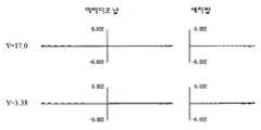
도 17은 본 발명에 의한 제 5실시예의 수차도17 is aberration diagram of a fifth embodiment of the present invention.
도 18은 본 발명에 의한 제 6실시예의 반사굴절 투영광학계를 표시한 광로도Fig. 18 is an optical path diagram showing a reflection refractive projection optical system of a sixth embodiment according to the present invention;
도 19는 본 발명에 의한 제 7실시예의 반사굴절 투영광학계를 표시한 광로도Fig. 19 is an optical path diagram showing a reflection refractive projection optical system of a seventh embodiment according to the present invention;
도 20은 본 발명에 의한 제 8실시예의 반사굴절 투영광학계를 표시한 광로도Fig. 20 is an optical path diagram showing a reflection refractive projection optical system of an eighth embodiment of the present invention.
도 21은 본 발명에 의한 제 9실시예의 반사굴절 투영광학계를 표시한 광로도Fig. 21 is an optical path diagram showing a reflection refractive projection optical system of a ninth embodiment according to the present invention.
도 22는 본 발명에 의한 제 6실시예의 수차도22 is aberration diagram of a sixth embodiment according to the present invention.
도 23은 본 발명에 의한 제 7실시예의 수차도23 is aberration diagram of a seventh embodiment according to the present invention.
도 24는 본 발명에 의한 제 8실시예의 수차도24 is aberration diagram of an eighth embodiment in accordance with the present invention
도 25는 본 발명에 의한 제 9실시예의 수차도25 is an aberration diagram of a ninth embodiment according to the present invention;
도 26은 본 발명에 의한 일측면의 예시적인 투영광학계를 표시한 개략블록단면도Fig. 26 is a schematic block sectional view showing an exemplary projection optical system of one side according to the present invention.
도 27은 디바이스(IC나 LSI 등의 반도체칩, LCD, CCD 등)의 제조를 설명하는 순서도Fig. 27 is a flowchart for explaining the manufacture of devices (semiconductor chips such as IC and LSI, LCDs, CCDs, etc.).
도 28은 도 27에 표시한 스텝 4의 상세 순서도.FIG. 28 is a detailed flowchart of step 4 shown in FIG. 27; FIG.
<도면의 주요부분에 대한 부호의 설명><Description of the symbols for the main parts of the drawings>
101: 제 1물체면102: 제 2물체면101: first object surface 102: second object surface
103: 개구조리개Gr1: 제 1결상광학계103: aperture stop Gr1: first imaging optical system
Gr2: 제 2결상광학계Gr3: 제 3결상광학계Gr2: 2nd imaging optical system Gr3: 3rd imaging optical system
IMG1: 제 1중간상IMG2: 제 2중간상IMG1: first intermediate image IMG2: second intermediate image
FM1: 제 1편향반사기FM2: 제 2편향반사기FM1: first deflective reflector FM2: second deflective reflector
L2: 제 2결상광학계의 왕복광학계 부분L2: reciprocating optical system part of the second imaging optical system
L: 물-상간 거리(제 1물체와 제 2물체의 광축(AX1)을 따라서 측정한 거리)L: water-phase distance (measured along the optical axis AX1 of the first object and the second object)
AX1, AX2, AX3: 광축AX1, AX2, AX3: optical axis
본 발명은 일반적으로, 투영광학계, 해당 투영광학계를 지닌 투영노광장치 및 디바이스의 제조방법에 관한 것이며, 특히, 레티클 패턴을 웨이퍼에 투영노광하는 투영광학계에 대해서 미러(거울, 즉, 반사경)를 이용한 반사굴절(catadioptric) 투영광학계에 관한 것이다.BACKGROUND OF THE INVENTION Field of the Invention The present invention generally relates to a projection optical system, a projection exposure apparatus having the projection optical system, and a manufacturing method of a device. In particular, a mirror (mirror, that is, a reflector) is used for a projection optical system that projects and exposes a reticle pattern onto a wafer. It relates to a catadioptric projection optical system.
반도체의 집적회로를 제조하기 위한 포토리소그라피 공정에 있어서, 마스크 또는 레티클 위의 패턴을, 투영광학계를 이용해서 포토레지스트 등이 도포된 웨이퍼 위에 투영노광하는 투영노광장치가 사용되고 있다. 근년, 집적회로의 고집적화가 진행됨에 따라, 투영노광 광학계에 대한 사양 및 성능도 점점 엄격해지고 있다.In a photolithography process for manufacturing an integrated circuit of a semiconductor, a projection exposure apparatus for projecting and exposing a pattern on a mask or a reticle onto a wafer coated with a photoresist or the like using a projection optical system is used. In recent years, as the integration of integrated circuits has progressed, the specifications and performance of projection exposure optical systems have become increasingly strict.
투영노광 광학계에 있어서 높은 해상력을 얻기 위해서는, 노광파장의 단파장화 및/또는 개구수("NA")의 고NA화가 필요로 된다. 높은 해상도를 얻기 위해 노광파장의 단파장화가 진행되고, 노광파장이 193nm(ArF)나 157nm(F2) 등의 파장영역에 달하면, 석영렌즈나 형석렌즈이외의 투과형 광학소자를 이용하면 높은 투과율이 거의 얻어지지 않으므로, 예정된 광량을 얻기 위해서는, 렌즈재료가 석영과 형석으로 한정되고 있다. 193nm나 157nm 등의 파장영역의 광을 이용하는 투영노광장치의 광학계로서, 예를 들면, 일본국 공개특허 평 10-79345호 공보(EP A1 828172에 대응함) 등에 개시되어 있는 바와 같은 오로지 굴절렌즈로 구성되고, 렌즈구성 매수가 많고 전체 유리재료의 두께가 큰 광학계를 이용한 경우, 광학계내에서의 광의 흡수량이 많아지므로, 웨이퍼 위에서의 노광량이 저하하여, 쓰루풋(throughput)의 저하의 원인으로 된다. 또, 렌즈의 열흡수 및 그 결과 온도의 상승에 의한 초점위치의 변동, (열)수차의 변동 등의 문제가 생기고 있다. 또, 노광파장이 193nm에서는 석영렌즈와 형석렌즈가 사용가능하나, 이들의 분산치의 차가 작으므로, 색수차의 보정이 곤란하여, 색수차를 보정하고자 하면 곡률반경이 작은 무색 면을 지닌 무색 렌즈가 복수개 필요하게 된다. 이와 같은 무색 렌즈가 광학계내에 복수개 있으면, 전체 유리재료 두께의 증대를 초래하여, 전술한 투과율의 저하, 열수차의 발생 등의 문제가 더욱 현저해지게 된다. 또, 형석에 관해서는, 투영광학계에 적합한 설계성능을 지닌 렌즈를 제공하는 것이 거의 곤란하고, 또한, 개구수가 큰 렌즈의 제조가 복잡화된다. 이것은 색보정을 더욱 복잡화해서, 비용증대의 요인으로 되고 있다. 또한, 노광파장이 157nm로 되면, 사용가능한 렌즈재료는 형석만으로 되어, 단일 재료만으로는 색수차를 보정하는 것은 곤란하다. 이와 같이, 굴절계만으로 투영광학계를 구성하는 것이 곤란하므로, 광학계중에 미러를 사용함으로써, 전술한 투과율의 저하, 색수차의 보정곤란성 등의 문제를 해결하고자 하는 제안이 여러 가지 이루어지고 있다.In order to obtain high resolution in the projection exposure optical system, short wavelength of exposure wavelength and / or high NA of numerical aperture ("NA") is required. When the exposure wavelength is shortened to obtain a high resolution, and the exposure wavelength reaches a wavelength region such as 193 nm (ArF) or 157 nm (F2 ), high transmittance is almost obtained by using a transmissive optical element other than quartz lens or fluorite lens. Since it is not obtained, in order to obtain a predetermined light quantity, the lens material is limited to quartz and fluorite. As an optical system of a projection exposure apparatus that uses light in a wavelength range of 193 nm or 157 nm, for example, it is composed of only refractive lenses as disclosed in Japanese Patent Laid-Open No. 10-79345 (corresponding to EP A1 828172). In the case of using an optical system having a large number of lens structures and having a large thickness of the entire glass material, the amount of light absorbed in the optical system increases, resulting in a decrease in the exposure amount on the wafer, resulting in a decrease in throughput. In addition, problems such as fluctuations in focus position and fluctuations in (thermal) aberration due to the heat absorption of the lens and the resultant temperature increase are caused. In addition, a quartz lens and a fluorite lens can be used at an exposure wavelength of 193 nm, but since the difference between these dispersion values is small, it is difficult to correct chromatic aberration. Done. When a plurality of such colorless lenses exist in an optical system, the thickness of the whole glass material will increase, and the problem of the fall of the said transmittance | permeability and generation | occurrence | production of thermal aberration will become more remarkable. As for fluorite, it is almost difficult to provide a lens having a design performance suitable for a projection optical system, and the production of a lens having a large numerical aperture is complicated. This further complicates color correction and causes cost increase. When the exposure wavelength is 157 nm, the usable lens material is only fluorite, and it is difficult to correct chromatic aberration only with a single material. As described above, since it is difficult to form the projection optical system using only the refractometer, various proposals have been made to solve the problems of the above-mentioned reduction in transmittance, difficulty in correcting chromatic aberration, and the like by using a mirror in the optical system.
예를 들면, 미러만으로 구성되어 있는 반사굴절 투영광학계가 일본국 공개특허 평 9-211332호 공보(미국특허 제 5,815,310호에 대응), 일본국 공개특허 평 10-90602호 공보(미국특허 제 5,686,728호에 대응) 등에 개시되어 있다. 또, 미러와 렌즈를 조합시킨 반사굴절 투영광학계가, 미국특허 제 5,650,877호 공보, 일본국 공개특허 소 62-210415호 공보, 일본국 공개특허 소 62-258414호 공보, 일본국 공개특허 평 2-66510호 공보(미국특허 제 4,953,960호에 대응), 일본국 공개특허 평 3-282527호 공보(미국특허 제 5,220,454호에 대응), 일본국 공개특허 평 5-188298호 공보(미국특허 제 5,668,673호에 대응), 일본국 공개특허 평 6-230287호 공보 (미국특허 제 5,592,329호에 대응), 일본국 공개특허 평 10-3039호 공보(EP A2 816892호에 대응), 일본국 공개특허 제 2000-47114호 공보(EP A2 989434호에 대응), 일본국 공개특허 평 8-62502호 공보(미국특허 제 5,861,997호에 대응), 일본국 공개특허 제 2002-83766호 공보(EP A2 1168028호에 대응) 등에 개시되어 있다.For example, a reflection refraction projection optical system composed only of a mirror is disclosed in Japanese Patent Application Laid-Open No. 9-211332 (corresponding to US Patent No. 5,815,310), and Japanese Patent Application Laid-open No. 10-90602 (US Pat. No. 5,686,728). Correspondence). In addition, a reflection refractive projection optical system combining a mirror and a lens is disclosed in U.S. Patent No. 5,650,877, Japanese Patent Laid-Open No. 62-210415, Japanese Patent Laid-Open No. 62-258414, and Japanese Patent Laid-Open No. 2 66510 (corresponding to U.S. Patent No. 4,953,960), JP-A-3-282527 (corresponding to U.S. Patent 5,220,454), and JP-A-5-188298 (U.S. Patent 5,668,673). Japanese Laid-Open Patent Publication No. 6-230287 (corresponding to US Patent No. 5,592,329), Japanese Laid-Open Patent Publication No. 10-3039 (corresponding to EP A2 816892), Japanese Laid-Open Patent Publication No. 2000-47114 Japanese Unexamined Patent Application Publication No. 8-62502 (corresponding to US Patent No. 5,861,997), Japanese Unexamined Patent Publication No. 2002-83766 (corresponding to EP A2 1168028), and the like. Is disclosed.
이와 같은 노광파장의 단파장화나 고 NA화에 대응해서 반사광학계를 포함하는 투영광학계를 구축할 때, 색수차보정이 가능한 것은 당연하고, 이상적으로는 상면 위에서 충분한 크기의 결상영역이 유지되는 동시에, 충분한 상측 작동거리를 확보할 수 있고, 또한, 간단한 구성을 제공하는 것이 바람직하다. 상면 위에서 충분히 큰 결상영역을 얻을 수 있다면, 주사형 투영노광장치에서는 쓰루풋상 유리하므로, 노광변동을 제어하는 것이 가능하다. 충분한 상측작동거리를 확보할 수 있으면, 장치의 오토포커스계나 웨이퍼 스테이지의 반송계 등을 구성하는 관점에서 바람직하고, 간단한 구성이면, 기계적 경통 등도 복잡화시키는 일이 없어, 조립 제조상의 이점이 있다.When constructing a projection optical system including a reflection optical system in response to such shortening and high NA of such an exposure wavelength, it is natural that chromatic aberration correction is possible. Ideally, an image forming region of sufficient size is maintained on the upper surface and a sufficient upper side. It is desirable to provide an operating distance and to provide a simple configuration. If a sufficiently large imaging area can be obtained on the image surface, the scanning projection exposure apparatus is advantageous in throughput, so that it is possible to control the exposure fluctuation. If a sufficient upper working distance can be ensured, it is preferable from the viewpoint of configuring the autofocus system of the apparatus, the conveying system of the wafer stage, and the like, and if it is a simple configuration, it does not complicate the mechanical barrel or the like, and there is an advantage in assembly manufacturing.
이상과 같은 시점으로부터 종래예에 대해서 검증하면, 먼저, 미국특허 제 5,650, 877호 공보에서는, 광학계중에 만긴 미러(Mangin mirror)와 굴절기를 배치해서, 레티클의 상을 웨이퍼에 노광하는 것이나, 이 광학계는, 사용하는 모든 화각에 있어서 동공의 중심부분의 차광(중공 조명)이 일어나는 동시에, 노광영역이 크게 될 수 없다고 하는 결점을 지니고 있다. 또, 노광영역을 크게 하고자 하면 동공의 중심부분의 차광이 크게 되어 바람직하지 않고, 또한, 만긴 미러의 굴절면이 광분할면을 형성하고 있어, 광이 그 면을 통과할 때마다 광강도가 절반으로 되어, 광강도가 10%정도로 저하해 버린다고 하는 등의 문제를 지니고 있다. 또, 일본국 공개특허 평 9-211332호 및 일본국 공개특허 평 10-90602호 공보에서는, 반사광학계를 사용하는 것을 기본으로 하고 있으나, 수차(페츠발(Petzval) 합계)가 악화되어 버린다고 하는 문제나, 미러 배치가 복잡화된다고 하는 문제 등으로부터 상면 위에서의 결상영역의 폭을 충분히 확보하는 것이 곤란하다. 또, 주로 상면 근방의 파워가 강한 오목면경이 결상작용을 지닌 구성으로 되어 있으므로 고NA화가 거의 곤란하며, 해당 오목면경의 직전 위치에 볼록면경이 배치되므로, 충분한 상측 작동거리를 확보할 수 없다고 하는 문제가 있다. 또, 일본국 공개특허 소 62-210415호 공보 및 일본국 공개특허 소 62-258414호 공보는, 카세그레인(Cassegrain)형이나 슈바르츠실트(Schwarzschild)형의 미러계를 응용해서, 미러 중심부에 개구를 형성함으로써 동공의 중공 조명을 일으켜 동공의 주변부분만을 결상에 기여시키는 광학계를 제안하고 있으나, 동공의 중공 조명의 결상성능에의 영향이 염려되고, 또 동공의 중공 조명을 적게 하고자 하면 필연적으로 미러의 파워가 크게 되므로, 미러에 입사하는 반사각도 커지고, 또한 고NA화를 도모하면 미러 직경이 현저하게 증대해버린다. 또한, 일본국 공개특허 평 5-188298호 공보 및 일본국 공개특허 평 6-230287호 공보에서는, 광로의 편향에 의해 장치의 구성이 복잡하고, 중간상을 최종 상에 결상시키는 광학소자의 파워의 대부분을 오목면경이 담당하고 있으므로, 구성상 고NA화가 곤란하고, 오목면경과 상면사이에 배치되어 있는 렌즈계는 축소계이며, 그의 배율이 정(+)의 부호이므로, 상측 작동거리가 충분히 확보될 수 없다. 또, 구성상, 광로분할이 필요하므로, 결상영역폭을 확보하는 것은 곤란하며, 광학계가 대형화하고 있으므로 풋프린트(foot-printing)에 대해서도 적합하지 않다.From the above point of view, the conventional example is verified. First, in US Patent Nos. 5,650 and 877, a mirror (mangin mirror) and a refractor are arranged in an optical system to expose an image of the reticle on a wafer, or this optical system Has the drawback that light shielding (hollow illumination) for the central portion of the pupil occurs at all angles of view used, and that the exposure area cannot be enlarged. In addition, if the exposure area is to be enlarged, shading of the central portion of the pupil becomes large, which is undesirable. Moreover, the refractive surface of the touched mirror forms a light splitting surface, and the light intensity is halved each time light passes through the surface. It has a problem that the light intensity drops to about 10%. In addition, Japanese Unexamined Patent Publications No. 9-211332 and Japanese Unexamined Patent Publication Nos. 10-90602 use a reflection optical system, but the aberration (Petzval sum) deteriorates. In addition, it is difficult to sufficiently secure the width of the imaging area on the upper surface due to the problem of complicated mirror arrangement. In addition, since the concave mirror having a strong power near the upper surface has an image forming action, high NA is hardly achieved, and since the convex mirror is disposed at the position immediately before the concave mirror, sufficient upper working distance cannot be secured. there is a problem. Japanese Laid-Open Patent Publications No. 62-210415 and Japanese Laid-Open Patent Publication Nos. 62-258414 employ a case system of Schassez or Schwarzschild to form an opening in the center of the mirror. This suggests an optical system that contributes to the image formation of the pupil by causing the hollow illumination of the pupil, but is concerned about the influence on the imaging performance of the hollow illumination of the pupil and inevitably reduces the power of the mirror. Since the larger the reflection angle incident on the mirror is, the higher the NA, the larger the mirror diameter is. Further, in Japanese Patent Laid-Open Nos. 5-188298 and 6-230287, the configuration of the device is complicated by the deflection of the optical path, and most of the power of the optical element for forming the intermediate phase into the final phase is obtained. Since the concave mirror is in charge, it is difficult to achieve high NA in construction, and the lens system disposed between the concave mirror and the upper surface is a reduction system, and its magnification is a positive sign, so that the upper working distance can be sufficiently secured. none. In addition, since optical path splitting is necessary in terms of construction, it is difficult to secure an imaging area width, and it is not suitable for foot-printing because the optical system is enlarged.
또, 일본국 공개특허 평 2-66510호 공보 및 일본국 공개특허 평 3-282527호 공보에서는, 먼저, 광로가 광스플리터(즉, 빔스플리터)에 의해 분할되어 있으므로, 경통구조가 복잡해지게 된다. 그리고, 직경이 큰 광스플리터를 필요로 하고, 이 광스플리터가 프리즘형인 경우에는 그 두께에 의해 광강도 손실이 크다. 고NA시에는 더욱 직경이 커지므로 광강도의 손실도 점점 커져 버린다. 빔스플리터가 평판형인 경우에는 축상 광선에 있어서도 비점수차, 코마수차가 발생해 버리는 문제가 있다. 또, 열흡수에 의한 비대칭 수차의 발생이나 광분할면에서의 특성변화에 의한 수차의 발생을 초래하여, 제조면에서 정밀도 양호한 빔스플리터를 작성하는 것도 곤란하다.In Japanese Patent Laid-Open Nos. 2-66510 and 3-282527, first, since the optical path is divided by an optical splitter (that is, a beam splitter), the barrel structure becomes complicated. In the case where an optical splitter having a large diameter is required, and the optical splitter is a prism type, the light intensity loss is large due to its thickness. At high NA, the diameter becomes larger, so that the loss of light intensity also increases. When the beam splitter is a flat plate type, there is a problem that astigmatism and coma aberration occur even in the axial light beam. It is also difficult to produce an asymmetric aberration due to heat absorption or an aberration due to a characteristic change in the light splitting surface, and to produce a beam splitter with high precision in manufacturing.
또, 일본국 공개특허 평 10-3039호 공보 및 일본국 공개특허 제 2000-47114호 공보에서는, 중간상을 1회 형성하는 2회 결상 반사굴절 광학계로서, 오목면경을 포함하는 왕복광학계를 지니고 물체(예를 들면, 레티클)의 중간상을 형성하는 제 1결상광학계와, 중간상을 제 2물체(예를 들면, 웨이퍼)면상에 결상하는 제 2결상광학계로 이루어진다. 일본국 공개특허 평 10-3039호 공보에서는, 그 중간상 근방에 광축 및 광을 편향시키기 위한 제 1평면경을 배치하고 있다. 또, 휘어진 광축은 대략 레티클 스테이지에 대해서 평행하게 편향되어, 제 2평면경에 의해 재차 편향되고, 혹은 제 2평면경없이 제 2물체 위에 결상된다. 또, 일본국 공개특허 제 2000-47114호 공보에서는, 제 1물체(예를 들면, 레티클)로부터의 광을 정(+)의 렌즈에 의해 굴절시키고, 제 1평면경에 의해 광축을 편향시키고, 오목면경을 포함하는 왕복광학계에 의해 반사된 광을 재차 제 1결상광학계중의 제 2평면경에 의해 제 2결상광학계를 지닌 제 2물체(예를 들면, 웨이퍼)에 투영하고 있다. 그 때문에, 상기 두 공보에 있어서, 필연적으로 제 1물체면(예를 들면, 레티클)과, 렌즈, 평면경 및 편향된 광은 서로 근접배치됨으로써, 제 1물체면(예를 들면, 레티클) 또는 레티클 스테이지와, 렌즈나 평면경과의 간섭이 문제로 되어, 충분한 공간을 확보하는 것이 곤란하다.In Japanese Patent Laid-Open Nos. 10-3039 and 2000-47114, a two-phase reflection refraction optical system for forming an intermediate image once, and having an reciprocating optical system including a concave mirror, For example, a first imaging optical system for forming an intermediate image of a reticle, and a second imaging optical system for forming an intermediate image on a surface of a second object (for example, a wafer). In Japanese Patent Laid-Open No. 10-3039, a first flat mirror for deflecting an optical axis and light is arranged in the vicinity of the intermediate image. Further, the curved optical axis is deflected substantially in parallel with respect to the reticle stage and is again deflected by the second plane mirror, or is imaged on the second object without the second plane mirror. In Japanese Patent Laid-Open No. 2000-47114, the light from the first object (e.g., a reticle) is refracted by a positive lens, the optical axis is deflected by a first plane mirror, and concave. The light reflected by the reciprocating optical system including the surface mirror is again projected onto the second object (for example, a wafer) having the second imaging optical system by the second plane mirror in the first imaging optical system. Therefore, in the above two publications, inevitably, the first object surface (e.g., reticle), the lens, the plane mirror, and the deflected light are arranged close to each other, whereby the first object surface (e.g., the reticle) or the reticle stage is arranged. The interference with the lens and the flat mirror becomes a problem, and it is difficult to secure sufficient space.
또, 일본국 공개특허 제 2002-83766호 공보의 도 13의 광학계 및 도 9의 광학계 및 일본국 공개특허 평 8-62502호 공보의 도 7 및 도 9의 광학계는, 중간상을 2회 형성하는 3회 결상 반사굴절 광학계이며, 제 1물체(예를 들면, 레티클)의 제 1중간상을 형성하는 제 1결상광학계, 제 1중간상으로부터 제 2중간상을 형성하고, 오목면경을 지닌 제 2결상광학계 및 제 2중간상을 제 2물체(예를 들면, 웨이퍼)면상에 결상하는 제 3결상광학계로 이루어진다. 제 2결상광학계는 왕복광학계로서 오목면경을 지니고 있다. 전자의 일본국 공개특허 제 2000-83766호 공보의 도 13의 NA 0.75인 광학계는, 제 1 및 제 2중간상 부근에 평면경(반사블록)을 배치하고, 제 1 및 제 3결상광학계의 광축을 서로 일치시킴으로써, 제 1물체(예를 들면, 레티클)와 제 2물체(예를 들면, 웨이퍼)를 평행하게 배치하고 있다. 그러나, 더욱 고NA에 대해서는, 수차보정의 관계상, 전체 길이(또는 제 1물체에서 제 2물체까지의 거리)가 너무 길어져 버린다고 하는 문제가 있다. 또, 제 1 및 제 2중간상의 위치근방에 광을 편향시키기 위한 평면경(반사블록)을 배치할 필요가 있으므로, 2매의 평면경 성능의 결상성능에 먼지나 흠집이 미치는 영향이 크다. 또, 제 1결상광학계에서 축소배율을 크게 유지(제 1결상광학계의 근축배율 |β1|가 0.625정도에 상당)하고 있으므로, 제 1물체(예를 들면, 레티클)에서의 물체측 NA에 대해서 제 1중간상에서는 그 축소배율분만큼 NA를 크게 함으로써, 결과로서 평면경에의 입사각도 범위가 크게 되어 버린다. 이것은 더욱 고NA화에 따라서 보다 심각한 문제로 된다. 즉, 더욱 고NA에 의해, 제 1결상광학계가 축소배율을 지나치게 부담하므로, 평면경에의 입사각도범위가 과도하게 크게 되기 때문에, 평면경의 막의 영향으로 P편광광과 S편광광간의 반사광 강도에 큰 차가 생겨 버리는 결과로 된다. 또, 축소배율을 제 1결상광학계에서 지나치게 부담하면, 제 1중간상의 상점이 낮아져 버려, 평면경에서 최저 화각의 전체의 광을 제 2결상광학계에 반사하는 것이 곤란해져 버린다. 또, 후자의 일본국 공개특허 평 8-62502호 공보의 도 7 및 도 9의 NA 0.45 내지 0.5인 광학계는, 마찬가지로 3회 결상, 또는, 중간상을 2회 형성하는 반사굴절형의 투영광학계이다. 이 타입의 투영광학계의 경우, 제 1물체(예를 들면, 레티클)와 제 2물체(예를 들면, 웨이퍼)를 평행하게 배치하기 위해서는 또 1매의 평면경을 필요로 한다. 그 경우에는, 전술한 공보중에도 기재되어 있는 바와 같이, 제 1결상광학계중에 미러를 배치하지 않으면 안되고, 제 1중간상 부근에 배치하면, 전술한 일본국 공개특허 제 2002-83766호 공보의 도 13의 광학계와 마찬가지의 배치로 된다. 또, 제 1결상광학계 및 제 2결상광학계에 있어서의 축소배율은 전체 계 축소배율에 대해서 상당히 영향을 미치고 있어(제 1결상광학계의 근축배율 |β1|이 0.438 내지 0.474정도임), 더욱 고NA화를 시도하고자 하면, 전자의 일본국 공개특허 제 2002-83766호 공보의 광학계와 마찬가지로 치명적인 문제를 일으킨다.In addition, the optical system of FIG. 13 and FIG. 9 of Unexamined-Japanese-Patent No. 2002-83766, and the optical system of FIGS. 7 and 9 of Unexamined-Japanese-Patent No. 8-62502 have 3 which forms an intermediate image twice. A first imaging optical system for forming a first intermediate image of a first object (e.g., a reticle), a second imaging optical system having a concave mirror, and a second imaging optical system for forming a second intermediate image from the first intermediate image It consists of a 3rd imaging optical system which forms an intermediate image on the surface of a 2nd object (for example, a wafer). The second imaging optical system has a concave mirror as a reciprocating optical system. The NA 0.75 optical system of FIG. 13 of the former Japanese Patent Application Laid-Open No. 2000-83766 has a planar mirror (reflective block) disposed near the first and second intermediate images, and the optical axes of the first and third imaging optical systems are mutually different. By matching, the 1st object (for example, a reticle) and a 2nd object (for example, a wafer) are arrange | positioned in parallel. However, for high NA, there is a problem that the total length (or the distance from the first object to the second object) becomes too long in view of aberration correction. In addition, since it is necessary to arrange a plane mirror (reflective block) for deflecting light in the vicinity of the position of the first and second intermediate images, the effect of dust and scratches on the imaging performance of the two plane mirror performances is large. In addition, since the reduction magnification is largely maintained in the first imaging optical system (the paraxial magnification | β1 | of the first imaging optical system corresponds to about 0.625), the first NA (object reticle) corresponds to the object side NA in the first object (for example, a reticle). In the middle phase, the NA is increased by the reduced magnification, resulting in a large incident angle range into the planar mirror. This becomes a more serious problem with higher NA. In other words, since the first imaging optical system excessively burdens the reduction magnification due to the higher NA, the range of angles of incidence into the plane mirror becomes excessively large, so that the reflected light intensity between the P-polarized light and the S-polarized light is large due to the film of the plane mirror. The result is a car. In addition, if the reduction magnification is excessively burdened by the first imaging optical system, the shops in the first intermediate image are lowered, and it becomes difficult to reflect the entire light of the lowest angle of view to the second imaging optical system in the planar mirror. The optical system of NA 0.45 to 0.5 in FIGS. 7 and 9 of the latter Japanese Laid-Open Patent Publication No. 8-62502 is a reflection-refractive projection optical system that similarly forms three times an image or two times an intermediate image. In this type of projection optical system, another plane mirror is required to arrange the first object (for example, a reticle) and the second object (for example, a wafer) in parallel. In that case, as described in the above-mentioned publications, a mirror must be arranged in the first imaging optical system, and when placed in the vicinity of the first intermediate image, the above-described Japanese Patent Application Laid-Open No. 2002-83766 The same arrangement as in the optical system is obtained. In addition, the reduction magnification in the first imaging optical system and the second imaging optical system has a significant influence on the overall system reduction magnification (the paraxial magnification | β1 | of the first imaging optical system is about 0.438 to 0.474). Attempting to make a fire, causing a fatal problem like the optical system of the former JP-A-2002-83766.
따라서, 본 발명의 예시적인 목적은 제 1물체(예를 들면, 레티클) 부근의 공간을 용이하게 확보할 수 있어, 기계적인 구성이 용이하고, 또, 평면경에 있어서의 막의 영향을 최소한으로 하는 것이 가능한 투영광학계를 제공하는 데 있다.Accordingly, an exemplary object of the present invention is to easily secure a space near the first object (for example, a reticle), to facilitate mechanical configuration, and to minimize the influence of the film on the plane mirror. To provide a possible projection optical system.
본 발명에 의한 일측면의 투영광학계는, 제 1물체쪽으로부터의 광로를 따라서(제 1물체쪽으로부터 출사하는 광이 통과하는 순서로), 적어도 1개의 렌즈를 지니고, 상기 제 1물체의 제 1중간상을 형성하는 제 1결상광학계와, 적어도 1개의 렌즈와 적어도 1개의 오목면경을 지니고, 상기 제 1물체의 제 2중간상을 형성하는 제 2결상광학계와, 적어도 1개의 렌즈를 지니고, 상기 제 1물체의 상을 제 2물체 위에 형성하는 제 3결상광학계를 구비해서, 상기 제 1물체의 상을 제 2물체 위에 결상하는 반사굴절 투영광학계에 있어서, 상기 제 1결상광학계의 근축배율을 β1, 상기 제 2결상광학계의 근축배율을 β2라 한 때, 0.70 < |β1·β2|< 3.0을 만족하는 것을 특징으로 한다.The projection optical system of one side according to the present invention has at least one lens along the optical path from the first object side (in the order in which light exiting from the first object side passes), and has a first lens of the first object. A first imaging optical system forming an intermediate image, a second imaging optical system having at least one lens and at least one concave mirror, forming a second intermediate image of the first object, and at least one lens, A reflection refractive projection optical system including a third imaging optical system for forming an image of an object on a second object, and forming an image of the first object on a second object, wherein the paraxial magnification of the first imaging optical system is β1, When the paraxial magnification of the second imaging optical system is β2, 0.70 <| β1 · β2 | <3.0 is satisfied.
또, 본 발명에 의한 다른 측면의 투영광학계는, 제 1물체의 상을 제 2물체 위에 투영하는 투영광학계에 있어서, 상기 제 1물체의 제 1중간상을 형성하며, 렌즈를 지닌 제 1결상광학계와, 상기 제 1물체의 제 2중간상을 형성하며, 상기 제 1물체쪽으로부터 차례로, 제 1편향반사기, 굴절렌즈군 및 오목면경을 지닌 제 2결상광학계와, 상기 제 1물체의 상을 제 2물체 위에 형성하며, 상기 렌즈와 상기 제 1편향반사기의 법선에 대해서 실질적으로 90°를 이루는 법선을 지니는 제 2편향반사기를 지닌 제 3결상광학계를 구비하고, 상기 제 1결상광학계, 상기 제 2결상광학계 및 상기 제 3결상광학계는, 이 순서로, 상기 제 1물체쪽으로부터의 광로를 따라서 배치되고, 상기 오목면경은 상기 제 1물체에 대향하도록 배치되고, 상기 제 1결상광학계로부터의 광은 상기 오목면경 및 상기 제 1편향반사기의 순으로 반사되어 상기 제 3결상광학계에 인도되고, 상기 제 1편향반사기로부터의 광은 상기 제 2편향반사기에서 편향되어서 상기 제 2물체로 인도되는 것을 특징으로 한다.The projection optical system according to another aspect of the present invention is a projection optical system for projecting an image of a first object onto a second object, forming a first intermediate image of the first object, and comprising a first imaging optical system having a lens; And a second imaging optical system having a first intermediate reflector, a refractive lens group, and a concave mirror, which in turn form a second intermediate image of the first object, and the image of the first object. A third imaging optical system formed thereon and having a second deflecting reflector having a normal that is substantially 90 ° with respect to the normal of the lens and the first deflecting reflector, wherein the first imaging optical system and the second imaging optical system And the third imaging optical system, in this order, is disposed along the optical path from the first object side, the concave mirror is disposed to face the first object, and the light from the first imaging optical system is concave. Light and is reflected in order of the first deflective reflector being led to the third imaging optical system, the light from the first deflective reflector is characterized by be deflected at the second deflective reflector that is led to the second object.
본 발명에 의한 다른 측면의 투영광학계는, 제 1물체의 상을 제 2물체 위에 투영하는 투영광학계에 있어서, 상기 제 1물체의 제 1중간상을 형성하며, 렌즈를 지닌 제 1결상광학계와, 상기 제 1물체의 제 2중간상을 형성하며, 상기 제 1물체쪽으로부터 차례로, 편향반사기, 굴절렌즈군 및 오목면경을 지닌 제 2결상광학계와, 상기 제 1물체의 상을 제 2물체 위에 형성하며, 렌즈를 지닌 제 3결상광학계를 구비하고, 상기 제 1결상광학계, 상기 제 2결상광학계 및 상기 제 3결상광학계는, 이 순서로, 상기 제 1물체쪽으로부터의 광로를 따라서 배치되고, 상기 오목면경은 상기 제 1물체에 대향하도록 배치되고, 상기 편향반사기는, 상기 제 1결상광학계로부터 상기 오목면경으로의 광과 상기 편향반사기를 반사한 광이 서로 교차하도록, 상기 제 2결상광학계의 광축에 대해서 소정의 각도를 이루도록 배치되는 것을 특징으로 한다.A projection optical system according to another aspect of the present invention is a projection optical system for projecting an image of a first object onto a second object, the first imaging optical system having a lens and forming a first intermediate image of the first object; Forming a second intermediate image of the first object, and sequentially forming a second imaging optical system having a deflective reflector, a refractive lens group and a concave mirror from the first object side, and an image of the first object on the second object; And a third imaging optical system having a lens, wherein the first imaging optical system, the second imaging optical system, and the third imaging optical system are arranged in this order along the optical path from the first object side, and the concave mirror Is disposed to face the first object, and the deflective reflector is arranged on the optical axis of the second imaging optical system so that light from the first imaging optical system and the light reflected by the deflecting reflector intersect each other. It is characterized in that it is arranged to achieve a predetermined angle with respect to.
본 발명에 의한 다른 측면의 투영광학계는, 제 1물체쪽으로부터의 광로를 따라서 적어도 1개의 렌즈를 지니고, 상기 제 1물체의 제 1중간상을 형성하는 제 1결상광학계와, 적어도 1개의 렌즈와 적어도 1개의 오목면경을 지니고, 상기 제 1물체의 제 2중간상을 형성하는 제 2결상광학계와, 적어도 1개의 렌즈를 지니고, 상기 제 1물체의 상을 제 2물체 위에 형성하는 제 3결상광학계를 구비해서, 상기 제 1물체의 상을 제 2물체 위에 결상하는 반사굴절 투영광학계에 있어서, 상기 제 1결상광학계의 근축배율을 β1이라 한 때, 0.7 < |β1|< 2.0을 만족하는 것을 특징으로 한다.According to another aspect of the present invention, a projection optical system includes a first imaging optical system having at least one lens along an optical path from a first object side and forming a first intermediate image of the first object, and at least one lens and at least one lens. A second imaging optical system having one concave mirror and forming a second intermediate image of the first object, and a third imaging optical system having at least one lens and forming an image of the first object on the second object. Thus, in the refraction-refractive projection optical system for forming the image of the first object on the second object, 0.7 <| β1 | <2.0 is satisfied when the paraxial magnification of the first imaging optical system is β1. .
본 발명에 의한 다른 측면의 투영광학계는, 제 1물체의 상을 제 2물체 위에 투영하는 투영광학계에 있어서, 렌즈를 지니고, 상기 제 1물체의 제 1중간상을 형성하는 제 1결상광학계와, 렌즈와 오목면경을 지니고, 상기 제 1물체의 제 2중간상을 형성하는 제 2결상광학계와, 렌즈를 지니고, 상기 제 1물체의 상을 제 2물체 위에 형성하는 제 3결상광학계를 구비하고, 상기 제 1결상광학계, 상기 제 2결상광학계 및 상기 제 3결상광학계는, 상기 제 1물체쪽으로부터의 광로를 따라서 상기 제 1결상광학계, 상기 제 2결상광학계 및 상기 제 3결상광학계의 순으로 배치되고, 상기 제 1결상광학계의 근축배율을 β1, 상기 제 2결상광학계의 근축배율을 β2, 상기 투영광학계의 상기 제 1물체쪽의 개구수를 NAo라 한 때, 3.5 < |β1·β2|/NAo < 20을 만족하는 것을 특징으로 한다.According to another aspect of the present invention, there is provided a projection optical system including a first imaging optical system having a lens and forming a first intermediate image of the first object in a projection optical system for projecting an image of a first object onto a second object. And a second imaging optical system having a concave mirror and forming a second intermediate image of the first object, and a third imaging optical system having a lens and forming an image of the first object on the second object. The first imaging optical system, the second imaging optical system and the third imaging optical system are arranged in the order of the first imaging optical system, the second imaging optical system and the third imaging optical system along the optical path from the first object side. When the paraxial magnification of the first imaging optical system is β1, the paraxial magnification of the second imaging optical system is β2, and the numerical aperture of the first object side of the projection optical system is NAo, 3.5 <| β1 · β2 | / NAo < It is characterized by satisfying 20.
본 발명에 의한 일측면의 노광장치는, 광원으로부터의 광을 이용해서 제 1물체를 조명하는 조명광학계와, 상기 제 1물체의 상을 제 2물체 위에 투영하는 상기 투영광학계를 구비한 것을 특징으로 한다.An exposure apparatus on one side according to the present invention includes an illumination optical system for illuminating a first object using light from a light source, and the projection optical system for projecting an image of the first object onto a second object. do.
본 발명에 의한 다른 측면의 디바이스의 제조방법은 상기 노광장치를 이용해서 제 2물체를 노광하는 공정과, 상기 노광된 제 2물체를 현상하는 공정을 구비한 것을 특징으로 한다.The device manufacturing method of the other aspect by this invention is characterized by including the process of exposing a 2nd object using the said exposure apparatus, and the process of developing the said exposed 2nd object.
본 발명의 기타 특징과 이점은 첨부도면과 관련하여 취한 이하의 상세한 설명으로부터 명백해질 것이며, 첨부도면에 있어서 동일한 참조 부호는, 도면을 통해서 동일 혹은 유사한 부분을 지칭하는 것이다.Other features and advantages of the present invention will become apparent from the following detailed description taken in conjunction with the accompanying drawings, in which like reference characters designate the same or similar parts throughout the figures thereof.
또, 본 발명의 일부를 구성하는 동시에 본 발명에 병합되는 첨부도면은 본 발명의 실시예를 예시하며, 발명의 상세한 설명과 함께, 본 발명의 원리를 설명하는데 이용된다.In addition, the accompanying drawings, which form a part of the invention, and which are incorporated into the invention, illustrate embodiments of the invention and, together with the description, serve to explain the principles of the invention.
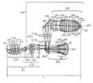
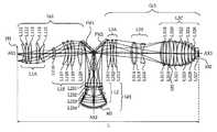
이하, 첨부도면을 참조해서, 본 발명의 일측면으로서의 반사굴절 투영광학계에 대해서 설명한다. 단, 본 발명은 이들 바람직한 실시예로 한정되는 것은 아니고, 본 발명의 정신과 목적 내에서 각 구성요소가 대체적으로 치환되어도 되고, 또, 광원에 레이저를 사용하고 있으나, 반드시 이것으로 한정할 필요는 없고, 수은램프나 크세논램프 등의 램프도 사용가능하다. 또한, 각 도면에 있어서, 동일한 부재에 대해서는 동일한 참조부호를 부여하고, 중복되는 설명은 생략한다. 여기서, 도 1은 본 발명의 일측면에 의한 반사굴절 투영광학계의 개략도이다. (101)은 제 1물체(예를 들면, 레티클), (102)는 제 2물체(예를 들면, 웨이퍼), (AX1) 내지 (AX3)은 광학계의 광축이며, 여기서의 광학계는 물체쪽으로부터 광이 통과하는 순으로, 제 1결상광학계(Gr1), 제 2결상광학계(Gr2) 및 제 3결상광학계(Gr3)를 포함한다. 제 1결상광학계(Gr1)는 제 1물체(101)의 상(제 1중간상(IMG1))을 형성하고, 제 1중간상으로부터의 광은 오목면경(M1) 및 왕복광학계 부분(L2)을 지닌 제 2결상광학계에 의해서 제 2중간상(IMG2)을 형성한다. 그 때, 제 1편향반사기(FM1)에 의해, 제 2결상광학계(Gr2)의 왕복광학계 부분(L2)에 의해서 제 1물체(101)방향에 반사된 광 및 광축(AX1)을 편향한다. 제 3결상광학계(Gr3)는 중간상(IMG2)의 상을 제 2물체(102) 위에 소정의 배율로 형성한다. 그 때, 제 3결상광학계중에 지닌 제 2편향반사기(FM2)에 의해, 제 1편향반사기(FM1)로부터 반사된 광을 편향하고 있다. 그것에 따라서 광축(AX2)은 도시한 바와 같이 광축(AX3)으로 편향된다.EMBODIMENT OF THE INVENTION Hereinafter, with reference to an accompanying drawing, the reflection refraction projection optical system as one side of this invention is demonstrated. However, the present invention is not limited to these preferred embodiments, and each component may be generally substituted within the spirit and object of the present invention, and a laser is used as the light source, but the present invention is not necessarily limited thereto. Lamps such as mercury lamps and xenon lamps may also be used. In addition, in each figure, the same code | symbol is attached | subjected about the same member and the overlapping description is abbreviate | omitted. 1 is a schematic diagram of a reflective refractive projection optical system according to one aspect of the present invention.
이와 같이 3회 결상광학계간의 조합과, 제 2결상광학계(Gr2)중에 지닌 오목면경(M1)과, 편향반사기(FM1), (FM2)에 의해 광을 편향함으로써, 제 1물체(101)와 렌즈 및 편향반사기 등과의 간섭을 피하는 것이 가능한 동시에, 3회 결상광학계로서는 물-상(즉, 물체와 상)간 거리가 작고 유효직경도 작은, 동공의 중심부의 차광이 없는, 축외광을 결상하는 투영광학계를 제공할 수 있게 된다.In this manner, the
여기서, 제 2결상광학계(Gr2)는 오목면경(M1)을 지니고 있고, 또, 광이 왕복하는 왕복광학계 부분(도면중 (L2))도 지니고 있다. 이 오목면경(M1)과 제 1결상광학계(Gr1)는 동일한 직선 광축(AX1)상에 있고, 그 오목면이 레티클면과 대향하도록 배치되어 있다. 이 제 2결상광학계(Gr2)중의 오목면경(M1)을 반사한 광은 제 2결상광학계(Gr2)중의 왕복광학계 부분(L2)을 통과한 후, 제 1편향반사기에 의해서 광축(AX1)을 (AX2)로 90° 휘게 한다. 이 때, 제 1결상광학계로부터 오목면경으로의 광과, 상기 오목면경으로부터 반사된 후에 상기 편향반사기를 반사한 광이 교차하도록, 상기 편향반사기를 광축에 대해서 소정의 각도로 배치하고 있다. 제 1편향반사기(FM1)를 반사한 광은 제 3결상광학계(Gr3)중에 배치되어 있는 제 2편향반사기(FM2)에 의해, 광축(AX2)으로부터 (AX3)으로 90° 휘어져 있다. 이와 같이, 2개의 편향반사기에 의해 2번 광축을 휘게 함으로써, 제 1물체(101)와 제 2물체(102)를 평행하게 배치하고 있다. 따라서, 도 1에 있어서의 제 1편향반사기와 제 2편향반사기는 그들의 반사면이 상대적으로 90°의 각도차를 지니도록 배치되어 있다. 도 1에서는 제 1물체(101)의 축외의 어느 물점로부터 나온 광이 제 1물체면(102) 위에 결상되는 태양을 표시하고 있으나, 본 발명은 제 1물체의 광축(AX1)으로부터 벗어난 어느 범위의 축외물점으로부터 나온 광을 사용하고 있다. 그 때, 제 1물체면상에 있어서, 광축을 포함하지 않는 직사각형의 슬릿영역 혹은 광축을 포함하지 않는 원호형상의 슬릿영역(노광영역)의 패턴이 제 2물체(102) 위에 노광된다.Here, the second imaging optical system Gr2 has a concave mirror M1, and also has a reciprocating optical system portion (L2 in the drawing) through which light reciprocates. The concave mirror M1 and the first imaging optical system Gr1 are on the same linear optical axis AX1, and the concave surface is disposed so as to face the reticle surface. The light that reflects the concave mirror M1 in the second imaging optical system Gr2 passes through the reciprocating optical system part L2 in the second imaging optical system Gr2, and then the optical deflection reflector makes the optical axis AX1 ( Bend 90 ° with AX2). At this time, the deflective reflector is disposed at a predetermined angle with respect to the optical axis so that the light from the first imaging optical system to the concave mirror intersects with the light reflected by the deflective reflector after being reflected from the concave mirror. The light reflected from the first deflective reflector FM1 is bent by 90 ° from the optical axis AX2 to AX3 by the second deflective reflector FM2 disposed in the third imaging optical system Gr3. In this way, the
또, 제 1결상광학계(Gr1)는 부(負)의 초점거리를 지니고 있고, 적어도 1개의 렌즈를 지니고 있다. 또, 제 2결상광학계(Gr2)는 정의 초점거리를 지니고 있고, 적어도 1개의 렌즈와 오목면경(M1)을 지니고 있다. 또한, 제 3결상광학계(Gr3)는 부의 초점거리를 지니고 있고, 적어도 1개의 렌즈를 지니고 있다. 그리고, 제 1결상광학계(Gr1) 및 제 3결상광학계(Gr3)에 의해 발생하는 색수자 및 정의 페츠발 합계를, 제 2결상광학계(Gr2)의 오목면경(M1) 및 렌즈에 의해 보정하고 있다.In addition, the first imaging optical system Gr1 has a negative focal length and has at least one lens. In addition, the second imaging optical system Gr2 has a positive focal length, and has at least one lens and a concave mirror M1. In addition, the third imaging optical system Gr3 has a negative focal length and has at least one lens. The sum of the color number and the positive Petzval generated by the first imaging optical system Gr1 and the third imaging optical system Gr3 is corrected by the concave mirror M1 and the lens of the second imaging optical system Gr2. .
또, 본 발명의 실시예에서는, 제 1결상광학계(Gr1)의 초점거리는 부, 제 2결상광학계(Gr2)의 초점거리는 정, 제 3결상광학계(Gr3)의 초점거리는 부로 설정하였으나, 이것으로 한정되는 것은 아니다. 제 1 내지 제 3결상광학계는 각각 그 초점거리가 부, 정, 혹은 무한대이어도 된다. 따라서, 제 1 내지 제 3결상광학계에 대해서 3개의 초점거리(부, 정 및 무한대)의 전체의 조합이 적용될 수 있다.Further, in the embodiment of the present invention, the focal length of the first imaging optical system Gr1 is negative, the focal length of the second imaging optical system Gr2 is positive, and the focal length of the third imaging optical system Gr3 is negative. It doesn't happen. The focal lengths of the first to third imaging optical systems may be negative, positive, or infinity, respectively. Therefore, the entire combination of three focal lengths (negative, positive and infinity) can be applied to the first to third imaging optical systems.
또한, 바람직하게는 이하의 조건식을 만족한다:In addition, the following conditional expression is preferably satisfied:
0.70 < |β1·β2|< 3.0~ (1)0.70 <| β1 ・ β2 | <3.0 ~ (1)
(식중, β1은 제 1결상광학계(Gr1)의 근축결상배율, β2는 제 2결상광학계(Gr2)의 근축결상배율임).(Wherein β1 is the paraxial imaging magnification of the first imaging optical system Gr1, and β2 is the paraxial imaging magnification of the second imaging optical system Gr2).
조건식(1)의 하한치보다도 낮으면, 제 1결상광학계(Gr1)와 제 2결상광학계(Gr2)의 합성배율이 지나치게 적게 되어, 이하의 [A] 내지 [C]의 어느 것인가의 상태로 되어 바람직하지 않다. 즉, [A] 편향반사기(FM1)에서 반사되어 제 3결상광학계(Gr3)의 방향으로 향하는 광과, 제 1결상광학계(Gr1)로부터 제 2결상광학계(Gr2)에 입사해가는 광이 분리될 수 없게 되면, 광학계가 구성될 수 없게 되어 버린다. [B] 제 2결상광학계의 근축배율(β2)이 지나치게 작은 축소배율로 되어, 특히 왕복광학계 부분에서의 비대칭 수차의 발생이 커서 결상성능을 악화시켜 버린다. [C] 특히 고NA를 지닌 광학계에 있어서는 편향을 목적으로 한 편향반사기에 입사하는 광의 입사각도 범위가 지나치게 커져 버린다. 이것은 제 1 및 제 2결상광학계에 의해 상당한 축소배율을 부담함으로써, 제 1물체로부터의 광의 퍼짐, 즉, 물체쪽 NA가 제 1 및 제 2결상광학계의 축소배율만큼 크게 되어 버리므로, 제 1편향반사기에 입사하는 광의 입사각도범위가 크게 되기 때문이다. 그 결과, 편향반사기의 반사막의 영향으로 P편광광과 S편광광간의 반사강도에 큰 차가 생겨 버린다. 이것은 NA 0.8이상, 특히, NA 0.85이상의 다수회 결상을 지닌 반사굴절 투영광학계에 있어서 보다 현저해진다.If it is lower than the lower limit of Conditional Expression (1), the combined magnification of the first imaging optical system Gr1 and the second imaging optical system Gr2 is too small, which is in a state of any of the following [A] to [C]. Not. That is, the light reflected from the [A] deflective reflector FM1 and directed toward the third imaging optical system Gr3 and the light incident on the second imaging optical system Gr2 from the first imaging optical system Gr1 are separated. If it becomes impossible, the optical system will not be able to be configured. [B] The paraxial magnification β2 of the second imaging optical system becomes too small a reduction magnification, and particularly, asymmetrical aberration occurs in the reciprocating optical system part, which causes deterioration of the imaging performance. [C] Especially in an optical system having a high NA, the incidence angle range of light incident on the deflective reflector for the purpose of deflection becomes too large. This imposes significant reduction magnification by the first and second imaging optical systems, thereby spreading the light from the first object, i.e., the NA on the object side becomes as large as the reduction magnification of the first and second imaging optical systems, and thus, the first deflection. This is because the incident angle range of light incident on the reflector becomes large. As a result, a large difference occurs in the reflection intensity between the P-polarized light and the S-polarized light under the influence of the reflective film of the deflective reflector. This is more pronounced in a reflective refractive projection optical system having multiple imagings of NA 0.8 or more, in particular NA 0.85 or more.
한편, 조건식(1)의 상한치를 초과하면, 제 1 및 제 2결상광학계의 합성배율이 지나치게 크므로, 제 1물체(101)를 제 2물체에 축소투영할 경우를 고려하면, 제 3결상광학계(Gr3)의 근축결상배율(β3)의 절대치가 지나치게 작게 되어, 수차보정이 곤란하게 된다. 또, 제 2중간상(IMG2) 부근의 렌즈의 유효직경이 지나치게 커져 버린다.On the other hand, if the upper limit value of the conditional formula (1) is exceeded, the synthesis magnification of the first and second imaging optical systems is too large, so that the third imaging optical system is considered when the
또, 보다 바람직하게는 이하의 조건식을 만족한다. 즉,More preferably, the following conditional expressions are satisfied. In other words,
0.80 < |β1·β2|< 2.0~(2) 0.80 <| β1 ・ β2 | <2.0 to (2)
바람직하게는 이하의 조건식을 만족한다. 즉,Preferably, the following conditional expressions are satisfied. In other words,
0.70 < |β1|< 2.0~(3)0.70 <| β1 | <2.0 ~ (3)
0.70 < |β2|< 2.0~(4)0.70 <| β2 | <2.0 ~ (4)
조건식(3)의 하한치보다도 낮으면, 제 1결상광학계(Gr1)의 결상배율 β1이 지나치게 크게(혹은 작게) 되어 버려, 제 1물체(101)의 상으로서의 제 1중간상(IMG1) 부근의 광과, 편향반사기(FM1)가 간섭해버려, 결과적으로 광이 차폐된다. 또, 상한치를 초과하면, 제 1중간상(IMG1)이 지나치게 크게 되어 버려, 제 1중간상(IMG1) 부근의 렌즈의 유효직경이 지나치게 커져 버리는 동시에, 다른 결상광학계(Gr2), (Gr3)에서의 배율제어가 곤란해져 버리므로 바람직하지 않다. 조건식(4)를 벗어나면, 배율이 실제 크기(즉, 등배)로부터 크게 벗어나게 되어, 제 2결상광학계(Gr2)중의 왕복광학계의 강한 파워에 기인한 상당한 비대칭성이, 비대칭성의 수차를 보정하는 것을 복잡하게 한다.If it is lower than the lower limit of Conditional Expression (3), the imaging magnification β1 of the first imaging optical system Gr1 becomes too large (or small), and the light in the vicinity of the first intermediate image IMG1 as the image of the
또, 더욱 바람직하게는 이하의 조건식을 만족한다:More preferably, the following conditional expression is satisfied:
0.80 < |β1|< 1.5~(5)0.80 <| β1 | <1.5 ~ (5)
0.80 < |β2|< 1.5~(6)0.80 <| β2 | <1.5 ~ (6)
조건식(5) 및 조건식(6)을 만족함으로써, 제 1 내지 제 3결상광학계의 배율부담을 보다 적정한 것으로 하는 것이 가능한 동시에, 보다 유효직경이 작고, 성능이 양호한 광학계를 달성하는 것이 용이해진다. 또, 제 1결상광학계의 배율 β1 이 실제 크기보다 크게 되면, 제 1편향반사기(FM1)로부터의 광과 제 1결상광학계(Gr1)로부터의 최저 화각의 광과의 광분리가 보다 용이해지고, 그 결과, 최대 화각이 낮아질 수 있다고 하는 이점도 있다.By satisfying Conditional Expression (5) and Conditional Expression (6), it is possible to make the magnification burden of the first to third imaging optical systems more appropriate, and to achieve an optical system having a smaller effective diameter and better performance. In addition, when the magnification β1 of the first imaging optical system is larger than the actual size, optical separation between the light from the first deflective reflector FM1 and the light of the lowest angle of view from the first imaging optical system Gr1 becomes easier. As a result, there is also an advantage that the maximum angle of view can be lowered.
또, 제 1결상광학계(Gr1)와 제 3결상광학계(Gr3)의 굴절 광학계 부분에 의해서 생기는 정의 페츠발 합계를, 제 2결상광학계(Gr2)중의 왕복광학계 부분의 부의 굴절력을 지닌 렌즈군(L2)과 오목면경(M1)에 의해서 생기는 부의 페츠발 합계가 상쇄시킬 수 있게 된다. 바람직하게는, 다음의 조건식을 만족한다. 즉,In addition, the lens group L2 having the negative refractive power of the reciprocating optical system portion in the second imaging optical system Gr2, the positive Petzval sum generated by the refractive optical system portions of the first imaging optical system Gr1 and the third imaging optical system Gr3. ) And the negative Petzval sum generated by the concave mirror M1 can be canceled out. Preferably, the following conditional expression is satisfied. In other words,
P1 > 0, P2 < 0 및 P3 > 0~ (7)P1> 0, P2 <0 and P3> 0 to (7)
(식중, P1은 제 1결상광학계의 페츠발 합계, P2는 제 2결상광학계의 페츠발 합계, P3은 제 3결상광학계의 페츠발 합계임).(Wherein P1 is the Petzval sum of the first imaging optical system, P2 is the Petzval sum of the second imaging optical system, and P3 is the Petzval sum of the third imaging optical system).
상기 조건은 오목면경(M1) 및 왕복광학계 부분(L2)을 지닌 결상광학계를 제 2결상광학계로서 배치하는 것이 가능해져, 상면만곡이 작은 결상광학계를 달성하는 것이 가능해진다. 만약, 조건식(7)을 벗어나면, 오목면경(M1) 및 왕복광학계 부분(L2)을 제 1결상광학계 혹은 제 3결상광학계로서 배치하는 것으로 되나, 전자는 오목면경(M1)으로부터의 반사광이 제 1물체(101) 부근으로 되돌아와 버리므로, 제 1물체(예를 들면, 레티클)와, 되돌아와 버린 광 및 부근의 렌즈와의 물리적 간섭이 일어나기 쉽게 되어, 기계적 구성이 복잡하게 되어 버린다. 또, 후자는 최종 결상계(또는 제 3결상광학계)에 오목면경(M1)을 이용하는 것으로 되어, 고NA광학계를 달성하고자 하면 광분리가 복잡하게 되어 버린다.Under the above conditions, it is possible to arrange the imaging optical system having the concave mirror M1 and the reciprocating optical system portion L2 as the second imaging optical system, thereby achieving an imaging optical system with a small top surface curvature. If the conditional expression (7) is out of the range, the concave mirror M1 and the reciprocating optical system portion L2 are disposed as the first imaging optical system or the third imaging optical system, but the electrons reflect the reflected light from the concave mirror M1. Since the object is returned to the vicinity of the
또, 도 1에 표시한 바와 같은 배치를 지닌 경우, 이하의 조건식을 만족하는 것이 바람직하다. 즉,Moreover, when it has the arrangement as shown in FIG. 1, it is preferable to satisfy the following conditional formulas. In other words,
0.2< (φGr2_max + φL3B_max)/(2Y) < 0.9~ (8)0.2 <(φGr2_max + φL3B_max) / (2Y) <0.9 to (8)
(식중, Y는 광축(AX1)과 (AX3)과의 거리, φGr2_max는 상기 제 2결상광학계(Gr2)에 있어서의 최대유효직경, φL3B_max는 제 3결상광학계(Gr3)에 있어서의 상기 제 2편향반사기(FM2)와 상기 2물체(102) 사이에 위치하는 렌즈군(L3B)에 있어서의 최대유효직경임). 조건식(8)의 하한치보다도 낮으면, 광축(AX1)과 (AX3)의 간격이 지나치게 멀어져 버려, 제 3결상광학계(Gr3)의 유효직경이 과도하게 커져 버린다. 상한치를 초과하면, 광축((AX1)과 (AX3)과의 간격이 지나치게 가까워 제 2결상광학계(Gr2)의 렌즈나 오목면경(M1)과, 제 3결상광학계(Gr3)의 렌즈군(L3B)이 간섭하여, 경통이 구성될 수 없게 되어 버린다.Where Y is the distance between the optical axes AX1 and AX3, φGr2_max is the maximum effective diameter in the second imaging optical system Gr2, and φL3B_max is the second deflection in the third imaging optical system Gr3. Maximum effective diameter in the lens group L3B positioned between the reflector FM2 and the two objects 102). If it is lower than the lower limit of the conditional expression (8), the distance between the optical axes AX1 and AX3 is too far apart, and the effective diameter of the third imaging optical system Gr3 becomes excessively large. When the upper limit is exceeded, the distance between the optical axes (AX1) and (AX3) is too close, so that the lens or concave mirror M1 of the second imaging optical system Gr2 and the lens group L3B of the third imaging optical system Gr3 This interference interferes with the construction of the barrel.
바람직하게는, 이하의 조건식을 만족한다. 즉,Preferably, the following conditional expressions are satisfied. In other words,
-0.01 < hM1/φM1< 0.10~ (9)-0.01 <hM1 / φM1 <0.10 to (9)
(식중, φM1은 오목면경(M1)의 유효직경, hM1은 오목면경(M1)에 있어서의 광축(AX1)으로부터의 최축외 주광선의 높이임).(Wherein, φ M1 is the effective diameter of the concave mirror M1, and hM1 is the height of the outermost principal axis from the optical axis AX1 in the concave mirror M1).
이와 같이, 제 2결상광학계의 오목면경(M1)을 동공 근방에 배치함으로써, 비점수차 등의 발생을 회피하는 것이 가능해진다.Thus, by arranging the concave mirror M1 of the second imaging optical system near the pupil, it is possible to avoid occurrence of astigmatism and the like.
또, 본 발명의 반사굴절 광학계는 적어도 1개의 편향반사기를 지니고 있다. 2개의 편향반사기를 지닌 경우, 제 2결상광학계(Gr2)중에 1개, 그리고 제 3결상광학계(Gr3)중에 1개 배치하는 것이 바람직하다. 특히 제 1결상광학계(Gr1)로부터의 광이 제 2결상광학계(Gr2)에 입사한 후에 오목면경(M1)에서 반사되어, 그 후에 제 1편향반사기에서 반사하도록 배치하는 것이 바람직하다. 즉, 제 1물체(101)로부터의 광이 제 1결상광학계(Gr1)에 의해 제 1중간상(IMG1)을 형성한 후, 제 2결상광학계(Gr2)중의 왕복광학계 부분(L2)에 입사한 후에, 오목면경(M1)에 의해 반사되어 재차 (L2)에 입사하고, (L2)로부터 출사된 광을 반사하도록 제 1편향반사기를 배치하는 것이 바람직하다.In addition, the reflective refractive optical system of the present invention has at least one deflective reflector. In the case of having two deflective reflectors, it is preferable to arrange one in the second imaging optical system Gr2 and one in the third imaging optical system Gr3. In particular, it is preferable that the light from the first imaging optical system Gr1 is reflected by the concave mirror M1 after being incident on the second imaging optical system Gr2, and then disposed so as to be reflected by the first deflecting reflector. That is, after the light from the
또, 제 2결상광학계(Gr2)에 입사하기 전의, 제 1결상광학계(Gr1)로부터의 광이 결상하는 제 1중간상(IMG1) 부근에 편향반사기를 배치하면, 오목면경(M1)이 제 1물체(101)와 평행하게 배치하는 것이 가능하지 않게 된다. 그러면, 중력의 방향을 광축(AX1)에 일치시킨 경우에는 강한 굴절력을 지닌 오목면경(M1)이나 왕복광학계 부분(L2)의 자체 중량 변형, 혹은 경통 등의 억제에 의한 결상성능의 열화가 현저해져 버린다. 또, 편향반사기는 제 3결상광학계(Gr3)중에 2개 지니고 있어도 된다. 그 경우에는 제 2결상광학계(Gr2)가 중간상(IMG2)을 결상한 직후, 혹은 렌즈를 개재한 후에 제 1편향반사기(FM1)를 배치하는 것으로 된다.Further, when the deflective reflector is disposed near the first intermediate image IMG1 where the light from the first imaging optical system Gr1 forms before entering the second imaging optical system Gr2, the concave mirror M1 becomes the first object. It becomes impossible to arrange | position parallel to 101. FIG. Then, when the direction of gravity coincides with the optical axis AX1, the deterioration of the imaging performance due to the suppression of the self-weight deformation of the concave mirror M1 or the reciprocating optical system portion L2 having a strong refractive power, or the barrel, etc. becomes remarkable. Throw it away. In addition, you may have two deflective reflectors in the 3rd imaging optical system Gr3. In this case, the first deflective reflector FM1 is disposed immediately after the second imaging optical system Gr2 forms the intermediate image IMG2 or after the lens is interposed therebetween.
또, 제 2편향반사기(FM2)는 제 1편향반사기(FM1)를 반사한 광이 제 2물체에 도달할 때까지의 공간의 어딘 가에 배치하는 것으로 된다. 그러한 경우, 제 1편향반사기(FM1)와 제 2편향반사기(FM2) 사이에 적어도 1매의 렌즈(정의 굴절력을 지닌 것이 바람직함)가 있는 것이 편향반사기를 소형화하므로 바람직하나, 필수는 아니다.The second deflective reflector FM2 is arranged somewhere in the space until the light reflected by the first deflective reflector FM1 reaches the second object. In such a case, it is preferable to have at least one lens (preferably having positive refractive power) between the first deflective reflector FM1 and the second deflective reflector FM2 in order to reduce the size of the deflective reflector, but this is not necessary.
도 1에 표시한 바와 같이, 제 1중간상(IMG1)을 형성한 후에 제 2결상광학계(Gr2)의 왕복광학계 부분(L2)에 입사하는 광에 있어서, 이들 사이, 즉 (IMG1)과 (L2) 사이에 렌즈가 없는 것이 바람직하다. 제 1중간상을 형성한 후에, 왕복광학계 부분(L1) 이외의 부분에 어떠한 렌즈가 존재하면, 이 렌즈가 편향반사기(FM1)와 간섭하게 될 가능성이 있어 그들의 구성이 복잡하게 될 가능성이 있으나, 단, 근접하고 있어도 기계적 구성이 가능하면 배치해도 관계없다.As shown in Fig. 1, in the light incident on the reciprocating optical system portion L2 of the second imaging optical system Gr2 after the formation of the first intermediate image IMG1, that is, between (IMG1) and (L2) It is preferable that there is no lens in between. After forming the first intermediate image, if any lens is present in a portion other than the reciprocating optical system portion L1, the lens may interfere with the deflective reflector FM1, which may complicate their configuration. Even if it is adjacent, you may arrange | position if a mechanical structure is possible.
또, 제 2결상광학계(Gr2)는 왕복광학계 부분(L2)을 지니나, 이 (L2)는 부의 굴절력을 지니고, 적어도 1매의 부의 굴절력을 지닌 굴절렌즈를 지닌다. 이 제 2결상광학계(Gr2)는 제 1물체(101)에 대해서 오목면을 향한, 부의 굴절력을 지닌 렌즈를 적어도 1매(바람직하게는, 2매) 구비하는 것이 바람직하다. 또, 이 왕복광학계 부분(L2)은 비구면을 지닌 렌즈를 적어도 1매 지니는 것이 바람직하다. 만약, 비구면을 이용하지 않는 경우에는 왕복광학계 부분(L1)에 복수매의 렌즈를 이용해서 파워를 분담하는 것이 바람직하다. 물론, 비구면을 이용한 경우에는 복수매의 렌즈를 이용해서, 왕복광학계 부분에 있어서의 수차발생을 더욱 제어하는 것이 가능하다. 또, 오목면경은 비구면을 지니고 있어도 된다.The second imaging optical system Gr2 has a reciprocating optical system part L2, but this L2 has negative refractive power and has a refractive lens having at least one negative refractive power. This second imaging optical system Gr2 is preferably provided with at least one lens (preferably two) having negative refractive power toward the concave surface with respect to the
또, 제 2결상광학계는 왕복광학계 부분(L2)과 오목면경(M1)의 선단에, 적어도 1개의 렌즈를 지니고 있어도 된다. 구체적으로는, 제 1편향반사기(FM1)와 제 2편향반사기(FM2) 사이에 제 2중간상(IMG2)이 있고, 그 제 1편향반사기(FM1)와 제 2중간상(IMG2) 사이에 렌즈가 존재할 경우가 있다. 그 경우, 제 2중간상(IMG2) 부근의 렌즈의 유효직경을 적게 하는 것이 가능해진다.In addition, the second imaging optical system may have at least one lens at the tip of the reciprocating optical system portion L2 and the concave mirror M1. Specifically, there is a second intermediate image IMG2 between the first deflective reflector FM1 and the second deflective reflector FM2, and a lens exists between the first deflective reflector FM1 and the second intermediate image IMG2. There is a case. In that case, it becomes possible to reduce the effective diameter of the lens in the vicinity of the second intermediate image IMG2.
또, 제 3결상광학계(Gr3)는 적어도 1개의 굴절기로 이루어지고, 정의 굴절력을 지닌 렌즈군(L3A)과, 적어도 1개의 굴절기로 이루어지고, 정의 굴절력을 지닌 렌즈군(L3B)으로 구성되어 있고, 제 2중간상(IMG2)의 상을 제 2물체(102) 위에 형성한다. 이 때, 렌즈군(L3B)은 부의 굴절력을 지닌 렌즈군을 지니고 있어도 된다. 또, 렌즈군(L3A)과 (L3B) 사이에 제 2편향반사기를 배치함으로써, 제 1물체(101)와 제 2물체(102)를 서로 평행하게 되도록 배치할 수 있다. 물론, 제 2중간상(IMG2)과 렌즈군(L3A) 사이에 제 2편향반사기를 배치해도 된다.The third imaging optical system Gr3 is composed of at least one refractor, a lens group L3A having positive refractive power, and is composed of at least one refractor and a lens group L3B having positive refractive power. The second intermediate phase IMG2 is formed on the
또, 편향반사기는 편향반사경으로 구성되어 있다. 이 거울의 형상은 평면판 형상이어도 큐브형상의 일부여도 상관없다. 또, 유리의 배면반사를 이용한 반사경이어도 된다. 또, 빔스플리터를 이용해서, 축상으로부터 축외의 광을 이용해도 된다.The deflective reflector is composed of a deflective reflector. The mirror may have a flat plate shape or a part of a cube shape. Moreover, the reflector using the back reflection of glass may be sufficient. In addition, the beam splitter may be used to use off-axis light from the axis.
또, 도 1에 배치되어 있는 바와 같이, 제 1결상광학계(Gr1)로부터 오목면경(M1)으로의 광과, 오목면경(M1)으로부터 반사된 후에 제 1편향반사기를 반사한 광이 교차하도록, 제 1편향반사기를 광축에 대해서 소정의 각도로 배치하면 된다. 이와 같이 배치하면, 제 1편향반사기(FM1)에 입사하는 주광선의 입사각을 적게 하는 것이 가능하므로, 제 1편향반사기(FM1)에의 최대입사각을 적게 하는 것이 가능해진다. 바람직하게는, 이하의 조건식을 만족하는 것이 바람직하다. 즉,As shown in FIG. 1, the light from the first imaging optical system Gr1 to the concave mirror M1 and the light reflected by the concave mirror M1 and then reflected by the first deflecting reflector cross each other. The first deflective reflector may be disposed at a predetermined angle with respect to the optical axis. In this way, the incident angle of the chief ray incident on the first deflective reflector FM1 can be reduced, so that the maximum incident angle to the first deflective reflector FM1 can be reduced. Preferably, the following conditional expression is satisfied. In other words,
20° < θp < 45°~ (10)20 ° <θp <45 ° ~ (10)
(식중, θp는 제 1물체의 축외로부터의 주광선과 상기 제 1편향반사기(FM1)의 반사면의 법선이 이루는 각도임). 조건식(10)의 하한치보다도 낮으면, 편향반사기의 반사면의 법선과 주광선이 이루는 각도가 지나치게 적어져, 편향반사기가 지나치게 크게 되어 버리거나, 부근의 렌즈의 굴절력을 너무 강하게 하지 않으면 안되므로, 성능이 악화되어 버린다. 상한치를 초과하면, 편향반사기에 입사하는 광의 각도가 크게 되어 버리므로 전술한 바와 같이 막 특성이 악화되어 버린다. 더욱 바람직하게는, 이하의 식(11)을 만족한다. 즉,(Wherein θp is an angle formed by the chief ray from outside the axis of the first object and the normal line of the reflecting surface of the first deflective reflector FM1). If it is lower than the lower limit of Conditional Expression (10), the angle between the normal line of the deflective reflector and the chief ray becomes too small and the deflective reflector becomes too large or the refractive power of the nearby lens must be made too strong, resulting in deterioration of performance. It becomes. When the upper limit value is exceeded, the angle of light incident on the deflective reflector becomes large, so that the film characteristics deteriorate as described above. More preferably, the following formula (11) is satisfied. In other words,
30° < θp < 44°~ (11)30 ° <θp <44 ° ~ (11)
또, 예를 들면, 도 7에 표시한 바와 같이, 제 1결상광학계(Gr1)로부터 출사하여 오목면경(M1)에 이르는 광로와, 제 1편향반사기에서 반사되어 제 2편향반사기에 이르는 광로가 교차하지 않도록 제 1편향반사기(FM1)를 배치하는 것도 가능하다.For example, as shown in FIG. 7, the optical path exiting from the first imaging optical system Gr1 to the concave mirror M1 and the optical path reflected from the first deflective reflector to the second deflective reflector cross each other. It is also possible to arrange the first deflective reflector FM1.
또한, 제 1물체(101)와 제 2물체(102)는 평행하게 배치되는 것이 바람직하나, 그것으로 한정되는 것은 아니다. 즉, 도 8에 표시한 바와 같이, 제 2편향반사기(FM2)없이 광학계를 구성해도 된다.In addition, the
또, 개구조리개(103)는 제 3결상광학계(Gr3)의 렌즈군(L3B) 중에 배치하는 것이 바람직하다. 또, 제 1결상광학계(Gr1)의 주광선이 광축(AX1)과 교차하는 부근에, 조합해서 혹은 단독으로 배치해도 된다.The
또한, 도 1에서는 광축(AX1)과 광축(AX2), 그리고, 광축(AX2)과 (AX3)은 직교해서 배치되어 있으나, 도 2에 표시한 바와 같이, 광축(AX1) 내지 (AX3)은 반드시 직교하고 있을 필요는 없다. 바람직하게는, 편향반사기(FM1)와 (FM2)가, 그들의 반사면이 90°의 각도차를 지니도록 배치되면 된다. 상대적으로 90°의 각도차로 배치하면, 제 1물체(101)와 제 2물체(102)가 평행하게 배치될 수 있기 때문이다. 단, 제 1물체(101)와 제 2물체(102)를 평행하게 배치할 필요가 없을 때는, 90°이외에 임의의 각도를 이용해도 된다.In addition, although the optical axis AX1 and the optical axis AX2 and the optical axis AX2 and AX3 are arrange | positioned orthogonally in FIG. 1, as shown in FIG. 2, the optical axes AX1 to AX3 are necessarily. It doesn't have to be orthogonal. Preferably, the deflective reflectors FM1 and FM2 are arranged so that their reflection surfaces have an angle difference of 90 degrees. This is because the
또, 제 2물체면이 광축방향으로 변동하면 배율의 변화를 줄이기 위해서, 적어도 상면측에서 텔레센트릭하게 구성하고 있는 것이 바람직하다. 또, 본 발명의 결상광학계는 NA 0.8이상, 특히 0.85이상의 매우 높은 NA를 지니는 경우에 특히 유효하다.Moreover, when the 2nd object surface fluctuates in the optical axis direction, it is preferable to comprise telecentric at least on the upper surface side, in order to reduce the change of magnification. In addition, the imaging optical system of the present invention is particularly effective when the NA has a very high NA of 0.8 or more, particularly 0.85 or more.
또, 본 발명의 광학계는 수차보정기구를 지니는 것이 가능하다. 예를 들면, 제 1결상광학계중에 렌즈를 광축방향으로 이동시키는 및/또는 광축에 수직방향이나 그외의 방향으로 이동시키는(렌즈를 편심시키는) 기구를 지니는 것이 가능하다. 또, 제 2결상광학계나 제 3결상광학계에도 마찬가지의 수차보정기구를 적용할 수 있다. 또한, 오목면경(M1)을 변형시키는 기구를 설치해서 수차보정을 행해도 된다.The optical system of the present invention can also have aberration correction mechanisms. For example, it is possible to have a mechanism in the first imaging optical system to move the lens in the optical axis direction and / or to move it in a direction perpendicular to the optical axis or in other directions (eccentric the lens). The same aberration correction mechanism can also be applied to the second imaging optical system and the third imaging optical system. Further, aberration correction may be performed by providing a mechanism for deforming the concave mirror M1.
또, 제 2물체(102)면과 광학계의 최종 유리면 사이(후술하는 도 3에 있어서의 제 2물체(102)면과 렌즈(L326) 사이)의 간극을 액체로 매립하는, 소위 액침(液浸) 구성(immersion structure)으로 해도 된다.Moreover, what is called liquid immersion which fills the clearance gap between the
또한, 중간상(IMG1)이나 (IMG2)의 근방에 시야 조리개를 설치해도 된다. 또, 제 2물체(102)면의 근방에 시야 조리개를 설치해도 된다. 특히, 광학계중에 회절광학소자를 이용하고, 또, 전술한 바와 같이 제 2물체면과 그 근방을 침지 구성으로 한 경우에는, 광학계의 최종 유리면에 시야를 제한하는 조리개를 설치하거나, 그 근방(예를 들면, 최종 유리면과 제 2물체(102)면 사이)에 시야 조리개를 배치하거나 하면, 회절광학소자에 있어서 발생하거나 혹은 발생하지 않는 섬광 등이 제 2물체면에 도달하는 것을 방지하는 것이 가능하다.In addition, a field stop may be provided near the intermediate image IMG1 or IMG2. In addition, a field stop may be provided near the surface of the
또, 광학계중에 회절광학소자를 이용하지 않고, 제 2물체면을 액침 구성으로 하는 것도 가능하다. 또한, 액침 광학계를 구성할 경우에는 회절광학소자의 유무에 관계없이, 그 액체의 성능 등이 광학계의 결상성능에 기여하는 영향을 최소한으로 할 필요성으로부터, 광학계의 최종면과 제 2물체면(102) 사이의 축상의 간격은 5㎜이하인 것이 바람직하고, 더욱 바람직하게는, 1㎜이하이다.It is also possible to make the second object surface a liquid immersion structure without using a diffraction optical element in the optical system. In the case of configuring the immersion optical system, the final surface and the
이하에, 본 발명의 실시예에 대해서 설명한다.EMBODIMENT OF THE INVENTION Below, the Example of this invention is described.
제 1실시예First embodiment
본 발명에 의한 제 1실시예의 투영광학계의 구체적인 구성을 도 3에 표시한다. 이 투영광학계는 제 1물체(레티클, 마스크 등에 그려진 패턴을 지니는 원화)의 패턴을 제 2물체 위에 투영하고, 제 1결상광학계, 제 2결상광학계 및 제 3결상광학계를 지니고 있다. 이 제 1실시예는 투영광학계에 관한 실시예이나, 본 발명은 이 출원에 한하지 않고, 이 투영광학계를 지닌 광학기기 및 노광장치에도 적용가능하며, 나아가서는, 본 실시예에 의한 투영광학계를 지니는 노광장치를 이용한 디바이스의 제조방법도 적용가능하다.3 shows a specific configuration of the projection optical system of the first embodiment according to the present invention. This projection optical system projects a pattern of a first object (the original image having a pattern drawn on a reticle, mask, etc.) onto the second object, and has a first imaging optical system, a second imaging optical system, and a third imaging optical system. This first embodiment relates to a projection optical system, but the present invention is not limited to this application, but can be applied to an optical device and an exposure apparatus having the projection optical system, and furthermore, the projection optical system according to the embodiment The manufacturing method of the device using an exposure apparatus is also applicable.
도 3중의 제 1결상광학계는 제 1물체쪽으로부터 차례로, 정의 굴절력을 지니는 굴절렌즈군(L1A)과, 정의 굴절력을 지닌 굴절렌즈군(L1B)으로 구성된다. 정의 굴절력을 지닌 굴절렌즈군(L1A)은 제 1물체(101)쪽으로부터의 광의 진행방향에 따라서 제 1물체쪽으로 오목면을 향한 메니스커스형상의 부 렌즈(L111), 대략 평면을 제 1물체쪽으로 향한 대략 평철(平凸: 한 면만 볼록한)형상의 비구면의 정 렌즈(L112), 제 1물체쪽으로 대략 볼록면을 향한 대략 평철형상의 정 렌즈(L113) 및 제 1물체쪽으로 그들의 오목면을 향한 2매의 메니스커스형상의 정 렌즈(L114), (L115)로 구성되어 있다. 정의 굴절력을 지닌 굴절렌즈군(L1B)은 제 1물체쪽으로 오목면을 향한 메니스커스형상의 비구면의 부 렌즈(L116)와, 제 1물체쪽으로 그들의 오목면을 향한 2매의 메니스커스형상의 정 렌즈(L117), (L118)와, 대략 평면을 제 1물체쪽으로 향한 대략 평철형상의 정 렌즈(L119)와, 제 1물체쪽으로 볼록면을 향한 대략 평철형상의 비구면의 정 렌즈(L120)로 이루어진다.The first imaging optical system shown in FIG. 3 is composed of a refractive lens group L1A having positive refractive power and a refractive lens group L1B having positive refractive power in order from the first object side. The refractive lens group L1A having positive refractive power has a meniscus-shaped sub-lens L111 facing the concave surface toward the first object according to the traveling direction of the light from the
제 2결상광학계(Gr2)는 제 1결상광학계로부터의 광의 진행방향을 따라서 부의 굴절력을 지닌 왕복광학계 부분(L2)과 오목면경(M1)으로 구성되어 있다. 그리고, 제 1물체쪽으로부터 차례로, 제 1물체쪽으로 오목면을 향한 대략 평요(平凹: 한 면만 오목한)형상의 렌즈(L211), 제 1물체쪽으로 오목면을 향한 메니스커스형상의 비구면렌즈(L212) 및 제 1물체쪽으로 오목면을 향한 오목면경(M1)으로 이루어진다.The second imaging optical system Gr2 is composed of a reciprocating optical system portion L2 and a concave mirror M1 having negative refractive power along the traveling direction of light from the first imaging optical system. Then, a lens L211 having a substantially flat shape concave toward the first object from the first object side in turn, and a meniscus-shaped aspherical lens facing the concave surface toward the first object ( L212) and a concave mirror M1 facing the concave surface toward the first object.
제 1결상광학계(Gr1)로부터의 광이 왕복광학계 부분(L2)에 입사한 후, 오목면경(M1)에서 반사되어, 재차 왕복광학계에 입사한 후, 편향반사기(FM1)에 의해 광축(AX1)이 (AX2)로 90° 휨으로써 광도 휘어져 제 2중간상(IMG2)을 형성한다. 편향반사기(FM1)는 제 2결상광학계와 제 3결상광학계 사이에 배치되어 있으나, 본 실시예와 같이 제 2중간상(IMG2)과 왕복광학계 부분(L2) 사이에 배치되는 것이 바람직하다. 또, 본 실시예에서는 편향반사기는 평면경을 이용하고 있다.After the light from the first imaging optical system Gr1 is incident on the reciprocating optical system part L2, it is reflected by the concave mirror M1, again enters the reciprocating optical system, and then enters the reciprocating optical system, and then the optical axis AX1 by the deflecting reflector FM1. The light is also bent by bending 90 degrees with this AX2 to form a second intermediate image IMG2. The deflective reflector FM1 is disposed between the second imaging optical system and the third imaging optical system, but is preferably disposed between the second intermediate image IMG2 and the reciprocating optical system part L2 as in the present embodiment. In this embodiment, the deflective reflector uses a flat mirror.
제 3결상광학계(Gr3)는 정의 굴절력을 지닌 굴절렌즈군(L3A)과, 정의 굴절력을 지닌 굴절렌즈군(L3B)으로 이루어진다. 정의 굴절력을 지닌 굴절렌즈군 (L3A)은 제 2결상광학계(Gr2)로부터의 광의 진행방향을 따라서 대략 평면을 제 2중간상(IMG2)쪽으로 향한 대략 평철형상의 비구면 정 렌즈(L311)와, 제 2중간상 (IMG2)쪽으로 그들의 볼록면을 향한 2매의 메니스커스형상의 정 렌즈(L312), (L313)로 이루어진다. 정의 굴절력을 지닌 굴절렌즈군(L3B)은 제 2물체(102)쪽으로 오목면을 향한 메니스커스형상의 정 렌즈(L314), 양면 볼록형상의 비구면 부 렌즈(L315), 제 2물체쪽으로 볼록면을 향한 메니스커스형상의 부 렌즈(L316), 제 2물체쪽으로 오목면을 향한 메니스커스형상의 비구면의 부 렌즈(L317), 제 2물체쪽과는 반대쪽으로 볼록면을 향한 메니스커스형상의 정 렌즈(L318), 대략 평면을 제 2물체쪽으로 향한 대략 평철형상의 비구면 정 렌즈(L319), 제 2물체쪽과는 반대쪽으로 오목면을 향한 메니스커스형상의 부 렌즈(L320), 개구조리개(103), 양면 볼록형상의 비구면의 정 렌즈(L321), 제 2물체쪽으로 오목면을 향한 메니스커스형상의 정 렌즈(L322), 대략 평면을 제 2물체쪽으로 향한 대략 평철형상의 비구면 정 렌즈 (L323), 제 2물체쪽으로 오목면을 향한 메니스커스형상의 비구면 정 렌즈(L324), 제 2물체쪽으로 오목면을 향한 메니스커스형상의 부 렌즈(L325) 및 제 2물체쪽으로 평면을 향한 평철형상의 정 렌즈(L326)로 이루어진다.The third imaging optical system Gr3 includes a refractive lens group L3A having positive refractive power and a refractive lens group L3B having positive refractive power. The refractive lens group L3A having positive refractive power has an approximately flat iron aspherical positive lens L311 facing a substantially flat plane toward the second intermediate image IMG2 along the traveling direction of the light from the second imaging optical system Gr2, and the second lens. It consists of two meniscus-shaped positive lenses L312 and L313 facing their convex surface toward the intermediate image IMG2. The refractive lens group L3B having positive refractive power has a meniscus positive lens L314 facing the concave surface toward the
또, 제 3결상광학계(Gr3) 중의 굴절렌즈군(L3A)과 (L3B) 사이에 제 2편향반사기(FM2)를 배치하고 있다. 제 2편향반사기(FM2)는 본 실시예의 경우 평면경이며, 제 1편향반사기로부터 반사된 광을 소정의 방향으로 휘게 하고 있다.The second deflective reflector FM2 is disposed between the refractive lens groups L3A and L3B in the third imaging optical system Gr3. The second deflective reflector FM2 is a planar mirror in the present embodiment, and bends the light reflected from the first deflective reflector in a predetermined direction.
또한, 본 실시예에서는, 제 1결상광학계(Gr1)는 정의 굴절력을 지닌 렌즈군(L1A)과 (L1B)으로 구성되어 있으나, 이 광학배치에 한정되는 것은 아니다. 예를 들면, 정(正) 부(負) 정(正)의 3군의 구성이거나, 부 정 부 정의 4군 구성이거나, 혹은 다른 구성이어도 된다. 또, 제 3결상광학계(Gr3)는 정의 굴절력을 지닌 (L3A)과, 정의 굴절력을 지닌 (L3B)를 구비한 광학배치를 포함하지만, 이것으로 한정되는 것은 아니다. 렌즈군(L3B)중에 부의 굴절력을 지닌 렌즈군을 지니고 있어도 되고, 이것이외의 구성이어도 된다.In addition, in the present embodiment, the first imaging optical system Gr1 is composed of the lens group L1A and L1B having positive refractive power, but is not limited to this optical arrangement. For example, a positive negative positive 3 group structure, an negative negative positive 4 group structure, or another structure may be sufficient. The third imaging optical system Gr3 includes, but is not limited to, an optical arrangement having (L3A) having positive refractive power and (L3B) having positive refractive power. The lens group L3B may have a lens group having negative refractive power, and a configuration other than this may be provided.
본 실시예는 투영배율은 1/4배이며, 기준파장은 157nm, 유리재료로서는 형석을 이용하고 있다.In this embodiment, the projection magnification is 1/4, the reference wavelength is 157 nm, and fluorite is used as the glass material.
또, 상측의 개구수는 NA = 0.87, 물-상간 거리(제 1물체면에서 제 2물체면까지)는 L=1483㎜이다. 또한, 물점이 약 4.25 내지 16.63㎜의 범위에서 수차보정되어 있어, 적어도 길이방향으로 26㎜, 폭으로 6㎜의 직사각형의 노광영역을 확보할 수 있다. 또, 개구조리개(103)는 (L320)과 (L321) 사이에 배치되어 있다.The numerical aperture on the upper side is NA = 0.87, and the water-phase distance (from the first object surface to the second object surface) is L = 1483 mm. In addition, the aberration is aberration-corrected in the range of about 4.25 to 16.63 mm, thereby ensuring a rectangular exposure area of at least 26 mm in the longitudinal direction and 6 mm in the width. In addition, the
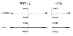
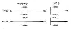
또, 본 실시예의 횡수차도를 도 5에 표시한다. 도 5에 있어서, Y= 4.25인 부분은 제 2물체에 있어서의 상점이 4.25㎜인 축외영역으로부터의 광의 횡수차도를 표시하고 있고, 한편, Y = 16.625인 부분은 제 1물체에 있어서의 상점이 16.625㎜인 축외영역으로부터의 광의 횡수차도를 표시하고 있다. 도 5는 기준파장 157.6nm ±0.6pm의 파장에 대해서 표시되어 있고, 단색 및 색수차가 양호하게 보정되어 있는 것을 알 수 있다.In addition, the lateral aberration diagram of this embodiment is shown in FIG. In Fig. 5, the portion of Y = 4.25 represents the lateral aberration diagram of light from the off-axis region where the store in the second object is 4.25 mm, while the portion of Y = 16.625 represents the store in the first object. The lateral aberration diagram of the light from the off-axis region of 16.625 mm is shown. Fig. 5 shows a reference wavelength of 157.6 nm ± 0.6 pm, and it can be seen that monochromatic color and chromatic aberration are well corrected.
또한, 사용하는 유리재료는 본 실시예에서는 형석만을 사용하였으나, 그 밖의 불화바륨칼슘이나 불화마그네슘칼슘 등의 유리재료를 조합해서 혹은 단독으로 사용해도 된다. 또, 193nm파장(ArF)에서 이용할 경우에는 석영과 형석을 함께 이용해도 되고, 석영만으로 구성해도 된다. 또한, 이것 이외의 유리재료를 이용해도 된다.In addition, although only the fluorite was used for the glass material used in the present Example, you may use combining other glass materials, such as barium calcium fluoride and magnesium calcium fluoride, independently. In addition, when using at 193 nm wavelength (ArF), you may use quartz and fluorite together, and you may comprise only quartz. Moreover, you may use glass materials other than this.
이하의 표 1 및 표 2에, 제 1실시예의 수치예의 명세를 표시한다. 또, 표중의 "i"는 제 1물체(101)로부터의 광의 진행방향을 따른 면번호, "ri"는 면번호에 대응한 각 면의 곡률반경, "di"는 각 면의 면간격을 표시한다. 렌즈유리재료 CaF2는 기준파장 λ= 157.6nm에 대한 굴절률을 1.56으로 하고 있다. 또, 기준파장에 대한 +0.6pm 및 -0.6pm의 파장의 굴절률은 각각 1.55999853 및 1.560000147이다. 또, 비구면의 형상은 다음식으로 부여되는 것으로 한다:In Table 1 and Table 2 below, specifications of numerical examples of the first embodiment are shown. In the table, "i" denotes a surface number along the advancing direction of light from the
x = (H2/4)/(1+((1-(1+k)·(H/ri)2))1/2) + AH4 + BH6 + CH8 + DH10 + EH12 + FH14 + GH16x = (H2 / 4) / (1 + ((1- (1 + k) · (H / ri) 2)) 1/2) + AH4 + BH6 + CH8 + DH10 + EH12 + FH14 + GH16
(상기 식중, X는 렌즈정점으로부터 광축방향으로의 변위량, H는 광축으로부터의 거리, ri는 곡률반경, k는 원추정수; A, B, C, D, E, F 및 G는 각각 비구면계수임).Where X is the displacement from the lens tip to the optical axis direction, H is the distance from the optical axis, ri is the radius of curvature, k is the conical constant; A, B, C, D, E, F and G are aspherical coefficients, respectively. ).


제 2실시예Second embodiment
도 4는 구체적인 렌즈구성을 표시한 것이다. 제 1결상광학계는 제 1물체쪽으로부터 차례로, 정의 굴절력을 지닌 굴절렌즈군(L1A)과 정의 굴절력을 지닌 굴절렌즈군(L1B)으로 구성된다. 정의 굴절력을 지닌 굴절렌즈군(L1A)은 제 1물체 (101)쪽으로부터의 광의 진행방향을 따라서 제 1물체쪽으로 오목면을 향한 메니스커스형상의 부 렌즈(L111), 대략 평면을 제 1물체쪽으로 향한 대략 평철(平凸: 한 면만 볼록한)형상의 비구면의 정 렌즈(L112), 제 1물체쪽으로 볼록면을 향한 대략 평철형상의 정 렌즈(L113), 양면 볼록형상의 정 렌즈(L114) 및 제 1물체쪽으로 볼록면을 향한 메니스커스형상의 정 렌즈(L115)로 구성되어 있다. 정의 굴절력을 지닌 렌즈군(L1B)은 제 1물체쪽으로 오목면을 향한 메니스커스 형상의 비구면의 부 렌즈(L116)와; 제 1물체쪽으로 그들의 오목면을 향한 3매의 메니스커스형상의 비구면 정 렌즈(L117), (L118), (L119)와; 제 1물체쪽으로 볼록면을 향한 대략 평철형상의 비구면의 정 렌즈(L120)로 이루어진다.4 shows a specific lens configuration. The first imaging optical system is composed of a refractive lens group L1A having a positive refractive power and a refractive lens group L1B having a positive refractive power in turn from the first object side. The refractive lens group L1A having positive refractive power has a meniscus-shaped sub-lens L111 facing the concave surface toward the first object along the traveling direction of the light from the
제 2결상광학계(Gr2)는 부의 굴절력을 지닌 왕복광학계 부분(L2)과 오목면경(M1)으로 구성되어 있다. 그리고, 제 1결상광학계(Gr1)로부터의 광의 진행방향을 따라서 오목면경(M1)쪽으로 볼록면을 향한 대략 평철형상의 렌즈(L211), 제 1물체쪽으로 오목면을 향한 대략 메니스커스형상의 부 렌즈(L212), 제 1물체쪽으로 오목면을 향한 대략 평요형상의 렌즈(L213), 제 1물체쪽으로 오목면을 향한 메니스커스형상의 비구면 렌즈(L214) 및 제 1물체쪽으로 오목면을 향한 오목면경(M1)으로 이루어진다. 제 1결상광학계(Gr1)로부터의 광이 왕복광학계 부분(L2)에 입사한 후, 오목면경(M1)에서 반사되어, 재차 왕복광학계 부분(L2)에 입사한 후, 편향반사기(FM1)에 의해 광축(AX1)이 광축(AX2)으로 휨으로써 광도 휘어서, 제 2중간상(IMG2)을 형성한다. 편향반사기(FM1)는 제 2결상광학계와 제 3결상광학계 사이에 배치되어 있으나, 본 실시예에 표시한 바와 같이 제 2중간상(IMG2)과 왕복광학계 부분(L2) 사이에 배치되는 것이 바람직하지만, 제 2중간상(IMG2)이 왕복광학계 부분(L2)과 편향반사기(FM2) 사이에 위치해도 된다. 또, 본 실시예에서는 편향반사기는 평면경을 이용하고 있다.The second imaging optical system Gr2 is composed of a reciprocating optical system portion L2 having a negative refractive power and a concave mirror M1. Then, a substantially flat convex lens L211 facing the convex surface toward the concave mirror M1 along the advancing direction of the light from the first imaging optical system Gr1, and the meniscus shape toward the concave surface toward the first object. Lens L212, a substantially flat lens L213 facing the concave surface toward the first object, a meniscus shaped aspheric lens L214 facing the concave surface toward the first object, and a concave surface toward the first object It consists of a surface diameter M1. After the light from the first imaging optical system Gr1 is incident on the reciprocating optical system part L2, it is reflected by the concave mirror M1, and again enters the reciprocating optical system part L2, and then by the deflective reflector FM1. The optical axis AX1 is also bent by the optical axis AX2, so that the light is bent to form the second intermediate image IMG2. The deflective reflector FM1 is arranged between the second imaging optical system and the third imaging optical system, but is preferably arranged between the second intermediate image IMG2 and the reciprocating optical system part L2 as shown in this embodiment. The second intermediate image IMG2 may be located between the reciprocating optical system portion L2 and the deflective reflector FM2. In this embodiment, the deflective reflector uses a flat mirror.
제 3결상광학계(Gr3)는 정의 굴절력을 지닌 굴절렌즈군(L3A)과, 정의 굴절력을 지닌 굴절렌즈군(L3B)으로 이루어진다. 정의 굴절력을 지닌 굴절렌즈군 (L3A)은 제 2결상광학계(Gr2)로부터의 광의 진행방향을 따라서 대략 평면을 제 2중간상(IMG2)쪽으로 향한 대략 평철형상의 비구면 정 렌즈(L311)와, 그들의 볼록면을 제 2중간상(IMG2)쪽으로 향한 2매의 메니스커스형상의 정 렌즈(L312), (L313)로 이루어진다. 정의 굴절력을 지닌 굴절렌즈군(L3B)은 제 2물체(102)쪽으로 오목면을 향한 메니스커스형상의 정 렌즈(L314), 양면 오목형상의 비구면 부 렌즈 (L315), 오목면을 제 2물체쪽으로 향한 메니스커스형상의 부 렌즈(L316), 볼록면을 제 2물체쪽과는 반대쪽으로 향한 대략 평철형상의 정 렌즈(L317), 양면 볼록형상의 비구면 정 렌즈(L318), 제 2물체쪽과는 반대쪽으로 오목면을 향한 메니스커스형상의 부 렌즈(L319), 개구 조리개(103), 양면 볼록형상의 비구면 정 렌즈(L320), 제 2물체쪽으로 오목면을 향한 메니스커스형상의 부 렌즈(L321), 제 2물체쪽으로 그들의 오목면을 향한 2매의 메니스커스형상의 비구면 정 렌즈(L322), (L323), 제 2물체쪽으로 그들의 오목면을 향한 2매의 메니스커스형상의 비구면 정 렌즈(L324), (L325), 제 2물체쪽으로 오목면을 향한 메니스커스형상의 부 렌즈(L326) 및 제 2물체쪽으로 평면을 향한 평철형상의 정 렌즈(L327)로 이루어진다. 또, 제 3결상광학계(Gr3)중의 굴절렌즈군(L3A)과 (L3B) 사이에 제 2편향반사기(FM2)를 배치하고 있다. 제 2편향반사기(FM2)는 본 실시예의 경우 평면경이며, 제 1편향반사기로부터 반사된 광을 소정의 방향으로 휘게 하고 있다.The third imaging optical system Gr3 includes a refractive lens group L3A having positive refractive power and a refractive lens group L3B having positive refractive power. The refractive lens group L3A having positive refractive power has an approximately flat iron aspherical positive lens L311 facing a substantially flat plane toward the second intermediate image IMG2 along the traveling direction of the light from the second imaging optical system Gr2, and their convexities. It consists of two meniscus-shaped positive lenses L312 and L313 facing the surface toward the second intermediate image IMG2. The refractive lens group L3B having positive refractive power has a meniscus positive lens L314 facing the concave surface toward the
또한, 본 실시예에서는, 제 1결상광학계(Gr1)는 렌즈군(L3A)과 (L3B)으로 구성되어 있으나, 그 구성으로 한정되는 것은 아니다. 예를 들면, 정 부 정의 3군의 구성으로 해도 되고, 또는 다른 구성이어도 된다.In addition, in the present embodiment, the first imaging optical system Gr1 is composed of lens groups L3A and L3B, but is not limited thereto. For example, it may be a structure of 3 groups of government definitions, or may be another structure.
본 실시예는, 투영배율은 1/4배이며, 기준파장은 157nm, 유리재료로서는 형석을 이용하고 있다. 또, 상측의 개구수는 NA = 0.86, 물-상간 거리(제 1물체면에서 제 2물체면까지)는 L=1425㎜이다. 또한, 물점이 약 3.25 내지 16.5㎜의 범위에서 수차보정되어 있어, 적어도 길이방향으로 26㎜, 폭으로 6㎜의 직사각형의 노광영역을 확보할 수 있다. 또, 개구조리개(103)는 (L320)과 (L321) 사이에 배치되어 있다.In this embodiment, the projection magnification is 1/4, the reference wavelength is 157 nm, and fluorite is used as the glass material. The numerical aperture on the upper side is NA = 0.86, and the water-phase distance (from the first object surface to the second object surface) is L = 1425 mm. In addition, the aberration is aberration-corrected in the range of about 3.25 to 16.5 mm, thereby ensuring a rectangular exposure area of at least 26 mm in the longitudinal direction and 6 mm in the width. In addition, the
또, 본 실시예의 횡수차도를 도 6에 표시한다. 도 6에 있어서, Y= 3.25인 부분은 제 2물체에 있어서의 상점이 3.25㎜인 축외영역으로부터의 광의 횡수차도를 표시하고 있다. 한편, Y = 16.5인 부분은 제 1물체에 있어서의 상점이 16.5㎜인 축외영역으로부터의 광의 횡수차도를 표시하고 있다. 도 6은 기준파장 157.6nm 및 ±0.6pm의 파장에 대해서 표시되어 있고, 단색 및 색수차가 양호하게 보정되어 있는 것을 알 수 있다.Moreover, the lateral aberration diagram of this embodiment is shown in FIG. In FIG. 6, the part where Y = 3.25 has shown the lateral aberration diagram of the light from the off-axis area | region whose shop in a 2nd object is 3.25 mm. On the other hand, the portion where Y = 16.5 indicates the lateral aberration diagram of the light from the off-axis region where the shop in the first object is 16.5 mm. Fig. 6 shows the reference wavelengths of 157.6 nm and wavelengths of ± 0.6 pm, and it can be seen that the monochrome and chromatic aberration are well corrected.
이하의 표 3 및 표 4에, 제 2실시예의 수치예의 명세를 표시한다. 또, 표중의 기호의 설명은 표 1과 동일하므로, 여기서는 그 설명을 생략한다.The specification of the numerical example of a 2nd Example is shown in following Table 3 and Table 4. In addition, since description of the symbol in a table is the same as that of Table 1, the description is abbreviate | omitted here.


다음에, 첨부도면을 참조해서, 본 발명에 의한 다른 측면으로서의 반사굴절 투영광학계에 대해서 설명한다. 상술한 바와 같이, 여기서는 도 1과 동일한 부재에 대해서는 동일한 참조부호를 붙이고, 중복하는 설명은 생략한다. 도 9에 있어서는 제 1결상광학계(Gr1)로부터의 광을 제 1편향반사기(FM1)에 대해서 편향시킴으로써(즉, 휘게 함으로써) 제 2결상광학계(Gr2)에 인도하고 있다. 또, 제 2결상광학계(Gr2)로부터의 광을 제 2편향반사기(FM2)에 의해 편향시켜, 제 3결상광학계(Gr3)로 인도하고 있다. 도 9에서는 편향반사기(FM1)와 (FM2)는 동일한 소자에 별개의 반사면을 형성해서 구성되어 있다. 또, 광축(AX1)과 (AX3)은 동일하게 구성되어 있다. (AX2)는 제 2결상광학계(Gr2)의 광축이고, (AX1)과 (AX2)와는 서로 직교하고 있다. 제 3결상광학계(Gr3)는 중간상(IMG2)의 상을 제 2물체(102) 위에 소정의 배율로 형성한다.Next, a reflection refraction projection optical system as another aspect according to the present invention will be described with reference to the accompanying drawings. As described above, the same members as in FIG. 1 are denoted by the same reference numerals, and redundant descriptions are omitted. In FIG. 9, the light from the first imaging optical system Gr1 is directed to the second imaging optical system Gr2 by deflecting (that is, bending) the first deflecting reflector FM1. The light from the second imaging optical system Gr2 is deflected by the second deflecting reflector FM2 and guided to the third imaging optical system Gr3. In Fig. 9, the deflective reflectors FM1 and FM2 are formed by forming separate reflective surfaces on the same element. In addition, optical axis AX1 and AX3 are comprised similarly. AX2 is an optical axis of the second imaging optical system Gr2, and is perpendicular to each other with AX1 and AX2. The third imaging optical system Gr3 forms the image of the intermediate image IMG2 on the
또, 제 1결상광학계(Gr1) 및 제 3결상광학계(Gr3)에 의해 발생하는 색수차 및 정의 페츠발 합계를 제 2결상광학계(Gr2)의 오목면경(M1) 및 렌즈에 의해 보정하고 있다.In addition, the chromatic aberration and the positive Petzval sum generated by the first imaging optical system Gr1 and the third imaging optical system Gr3 are corrected by the concave mirror M1 and the lens of the second imaging optical system Gr2.
또한, 이하의 조건식을 만족하는 것이 바람직하다:In addition, it is desirable to satisfy the following conditional expression:
0.70 < |β1|< 2.0···(12)0.70 <| β1 | <2.0 (12)
(식중, β1은 제 1결상광학계(Gr1)의 근축결상배율임).(Wherein β1 is the paraxial imaging magnification of the first imaging optical system Gr1).
조건식(12)의 하한치보다도 낮으면, 제 1결상광학계(Gr1)의 결상배율 β1이 지나치게 작은 축소배율로 되어 버려, 제 1편향반사기(FM1)에 입사하는 광의 입사각도범위가 지나치게 커져 버린다. 입사각도범위가 지나치게 커지면, 평면경의 막의 특성을 제어하는 것이 복잡해져서 바람직하지 않게 된다. 한편, 상한치를 초과하면, 제 1중간상(IMG1)이 지나치게 커져 버려, 제 1중간상(IMG1) 부근의 렌즈의 유효직경이 커져버리는 동시에, 다른 결상광학계(Gr2), (Gr3)에서의 배율제어가 곤란해지므로 바람직하지 않다.If it is lower than the lower limit of the conditional expression (12), the imaging magnification β1 of the first imaging optical system Gr1 becomes too small a reduction magnification, and the incident angle range of the light incident on the first deflective reflector FM1 becomes too large. If the incidence angle range is too large, controlling the properties of the film of the planar mirror becomes complicated and undesirable. On the other hand, when the upper limit value is exceeded, the first intermediate image IMG1 becomes too large, and the effective diameter of the lens near the first intermediate image IMG1 becomes large, and magnification control in other imaging optical systems Gr2 and Gr3 is performed. It is not preferable because it becomes difficult.
또, 보다 바람직하게는, 이하의 조건식을 만족한다:More preferably, the following conditional expression is satisfied:
0.80 < |β1|< 1.5···(13).0.80 <
조건식(13)을 만족함으로써, 제 1 내지 제 3결상광학계의 배율제어를 보다 적정하게 하는 동시에, 유효광학계의 직경을 작게 하는 것이 가능해진다. 또, 제 1결상광학계의 배율 β1이 1이상으로 되면, 제 1편향반사기(FM1)와 제 1결상광학계 (Gr1)의 최저화각의 광과의 광분리가 보다 용이해지고, 그 결과, 최대화각을 낮추는 것이 가능하다고 하는 이점도 있다.By satisfying the conditional expression (13), it is possible to more appropriately control the magnification of the first to third imaging optical systems and to reduce the diameter of the effective optical system. Further, when the magnification β1 of the first imaging optical system becomes 1 or more, optical separation between the first deflection reflector FM1 and the light of the lowest angle of view of the first imaging optical system Gr1 becomes easier, and as a result, the maximum angle is increased. There is also an advantage that it can be lowered.
또, 제 1결상광학계(Gr1)와 제 3결상광학계(Gr3)의 굴절광학계 부분에 의해서 생기는 정의 페츠발 합계를, 제 2결상광학계(Gr2)중의 왕복광학계 부분의 부의 굴절력을 지닌 렌즈군(L2)과 오목면경(M1)에 의해서 생기는 부의 페츠발 합계로 보정하는 것이 가능하다. 바람직하게는, 이하의 조건식을 만족한다:In addition, the lens group L2 having a negative refractive power of the reciprocating optical system portion in the second imaging optical system Gr2 is added to the sum of positive Petzval generated by the refractive optical system portions of the first imaging optical system Gr1 and the third imaging optical system Gr3. ) And the negative Petzval sum generated by the concave mirror M1 can be corrected. Preferably, the following conditional expression is satisfied:
P1 > 0, P2 < 0 및 P3 > 0···(14)P1> 0, P2 <0 and P3> 0 (14)
(식중, P1은 제 1결상광학계(Gr1)의 페츠발 합계, P2는 제 2결상광학계(Gr2)의 페츠발 합계, P3은 제 3결상광학계(Gr3)의 페츠발 합계임).(Wherein, P1 is the Petzval sum of the first imaging optical system Gr1, P2 is the Petzval sum of the second imaging optical system Gr2, and P3 is the Petzval sum of the third imaging optical system Gr3.
상기 조건을 만족함으로써, 오목면경(M1) 및 왕복광학계 부분(L2)을 제 2결상광학계로서 배치하는 것이 가능하며, 상면만곡이 작은 결상광학계를 달성하는 것이 가능해진다. 만약, (14)식의 조건식을 벗어나면, 오목면경(M1) 및 왕복광학계 부분(L2)을 제 1 혹은 제 3결상광학계로서 배치하는 것으로 되나, 전자는 오목면경 (M1)으로부터의 반사광이 제 1물체(101) 부근으로 되돌아와 버리므로, 제 1물체(101)(예를 들면, 레티클)와, 되돌아와 버린 광 및 부근의 렌즈와의 물리적 간섭이 일어나기 쉽게 되어, 기계적 구성이 곤란하게 되어 버린다. 또, 후자는 최종 결상계(제 3결상광학계)에 오목면경(M1)을 이용하는 것으로 되어, 고NA광학계를 달성하고자 하면 광분리가 복잡해진다.By satisfying the above conditions, the concave mirror M1 and the reciprocating optical system portion L2 can be arranged as the second imaging optical system, and it is possible to achieve an imaging optical system with small top surface curvature. If the conditional expression of the formula (14) is out of the equation, the concave mirror M1 and the reciprocating optical system portion L2 are arranged as the first or third imaging optical system, but the electrons reflect the reflected light from the concave mirror M1. Since the object is returned to the vicinity of the
바람직하게는, 이하의 조건식을 만족한다:Preferably, the following conditional expression is satisfied:
-0.10 ≤ hM1/φM1 < 0.10···(15)-0.10 ≤ hM1 / φM1 <0.10 (15)
(식중, φM1은 오목면경(M1)의 유효직경, hM1은 오목면경(M1)에 있어서의 광축(AX2)으로부터의 최축외 주광선의 높이임).(Wherein, φ M1 is the effective diameter of the concave mirror M1, and hM1 is the height of the outermost principal axis from the optical axis AX2 in the concave mirror M1).
이와 같이, 제 2결상광학계(Gr2)의 오목면경(M1)을 동공 근방에 배치함으로써, 비점수차 등을 저감시키는 것이 가능해진다. 더욱 바람직하게는, 이하의 조건을 만족한다:In this way, by placing the concave mirror M1 of the second imaging optical system Gr2 near the pupil, it is possible to reduce astigmatism and the like. More preferably, the following conditions are satisfied:
-0.05 ≤ hM1/φM1 < 0.05···(16).-0.05? HM1 /? M1 <0.05 ... (16).
또, 도 9에 있어서, 편향반사기(FM1)와 (FM2)는 반드시 동일한 소자로 구성할 필요는 없고, 별개의 소자로 구성해도 된다. 또, 제 1결상광학계(Gr1)의 광축과 제 3결상광학계(Gr3)의 광축은 동일하지 않아도 된다. 이들은 일직선상에 없어도 된다. 특히, 일직선상에 없어도 양 광축이 평행하게 배치되어 있으면, 제 1물체(101)와 제 2물체(102)를 평행하게 배치하는 것이 가능하다. 또, 제 2결상광학계(Gr2)의 광축(AX2)과 제 1결상광학계(Gr1)의 광축(AX1)이 반드시 직교하고 있을 필요는 없다. 예를 들면, 제 1물체(101)와 제 2물체(102)가 평행하게 배치되면, 광축(AX1)과 (AX2)은 렌즈나 반사부재 등과의 간섭이 일어나지 않는 한, 서로 임의의 각도를 지니고 있어도 된다.In addition, in FIG. 9, the deflective reflector FM1 and FM2 do not necessarily need to be comprised by the same element, but may be comprised by a separate element. The optical axis of the first imaging optical system Gr1 and the optical axis of the third imaging optical system Gr3 do not have to be the same. They do not have to be in a straight line. In particular, if both optical axes are arranged in parallel even without being in a straight line, it is possible to arrange the
또, 도 10 및 도 11에 표시한 바와 같이, 제 2결상광학계(Gr2)에 대해서, 오목면경(M1)으로 향하는 광과 오목면경(M1)으로부터 반사된 광이 서로 교차하는 바와 같은 배치를 취해도 된다. 이 경우, 도 10에 표시된 배치에 의하면, 제 1물체(101)로부터의 광을 제 1편향반사기(FM1)에 의해 편향시킨 광과, 상기 제 1편향반사기(FM1)에 의해 반사된 상기 광을 오목면경(M1)에 의해 반사한 후 제 2편향반사기(FM2)로 향하는 광이 교차하도록 편향반사기를 배치하고 있다. 상기 도 10 및 도 11과 같은 배치를 취하면, 2개의 편향반사기(FM1), (FM2)에 입사하는 주광선의 입사각도를 감소시키는 것이 가능해진다. 또, 이상과 같은 본 발명의 실시예의 일례로서의 도 9, 도 10 및 도 11과 같은 광학배치를 지닌 경우, 광을 편향하기 위한 편향반사기를 제 1결상광학계(Gr1)와 제 2결상광학계(Gr2) 사이와, 제 2결상광학계(Gr2)와 제 3결상광학계(Gr3) 사이에 지니고 있다. 여기서, 제 1물체(101)와 제 2물체(102)를 대략 평행하게 배치하기 위해서는 2개의 편향반사기의 그 반사면이 상대적으로 90°의 각도차로 배치될 필요가 있다. 또, 제 1물체(101)와 제 2물체(102)를 대략 평행하게 배치할 필요가 없을 경우에는 제 2편향반사기(FM2)는 없어도 된다. 그 경우, 제 2물체(102)와 오목면경(M1)은 대향하도록 배치되어 있다.In addition, as shown in FIG. 10 and FIG. 11, even if the light toward the concave mirror M1 and the light reflected from the concave mirror M1 intersect with each other with respect to the second imaging optical system Gr2, the arrangement is performed. do. In this case, according to the arrangement shown in Fig. 10, the light deflected by the first deflective reflector FM1 from the
도 10 및 도 11과 같이 구성하면, 편향반사기(FM1), (FM2)에의 주광선의 입사각도를 45°보다 작게 제어하는 것이 가능하다. 이와 같은 구성을 취할 경우, 바람직하게는, 이하의 조건식을 만족한다:10 and 11, it is possible to control the incident angles of the chief rays of light to the deflective reflectors FM1 and FM2 smaller than 45 degrees. When taking such a configuration, preferably, the following conditional expression is satisfied:
20° < θp < 45°···(17)20 ° <θp <45 °
(식중, θp는 제 1물체의 축외로부터의 주광선과 상기 제 1편향반사기(FM1)의 반사면의 법선이 이루는 각도임). 조건식(17)의 하한치보다도 낮으면, 제 1편향반사기의 반사면의 법선과 주광선이 이루는 각도가 지나치게 작게 되어 버려, 편향반사기가 지나치게 커져서, 주변의 렌즈의 굴절력을 비정상적으로 강하게 하지 않으면 안되므로 성능이 악화되어 버린다. 한편, 상한치를 초과하면, 왕복광학계 부분(L2)에 강한 굴절력을 지닌 렌즈가 필요로 되어 버리므로, 색수차의 보정이 곤란하게 되거나, 혹은 오목면경(M1)과 편향반사기(FM1)와의 거리가 매우 커져 버려, 장치가 대형화되어 버린다.(Wherein θp is an angle formed by the chief ray from outside the axis of the first object and the normal line of the reflecting surface of the first deflective reflector FM1). If it is lower than the lower limit of the conditional expression (17), the angle between the normal line and the chief ray of the reflecting surface of the first deflective reflector becomes too small, and the deflective reflector becomes too large, so that the refractive power of the surrounding lens must be abnormally strong, resulting in poor performance. It gets worse. On the other hand, if the upper limit value is exceeded, a lens having a strong refractive power is required for the reciprocating optical system portion L2, so that chromatic aberration correction becomes difficult, or the distance between the concave mirror M1 and the deflective reflector FM1 is very large. It becomes large and the apparatus becomes large.
보다 바람직하게는, 이하의 식(18)을 만족한다:More preferably, the following formula (18) is satisfied:
30° < θp < 44°···(18).30 ° <θp <44 ° ... (18).
식(18)을 만족함으로써, 보다 양호한 결상성능을 얻는 것이 가능한 동시에, 각 소자 및 광학계의 소형화를 달성하는 것이 가능하다.By satisfying equation (18), it is possible to obtain better imaging performance and at the same time achieve miniaturization of each element and optical system.
또, 본 발명의 광학계는 제 2결상광학계(Gr2)에 왕복광학계 부분(L2)을 지니나, 이 (L2)는 부의 굴절력을 지니고, 적어도 1매의 부의 굴절력을 지닌 렌즈로 이루어진다. 이들 부의 굴절력을 지닌 렌즈중 적어도 1매는 제 1물체(101)에 대해서 오목면을 향하고 있는 것이 바람직하다. 또, 이 왕복광학계 부분(L2)은 비구면을 지닌 렌즈를 적어도 1매 지니는 것이 바람직하다. 만약, 비구면을 지니지 않을 경우에는 왕복광학계 부분(L1)에 복수매의 렌즈를 이용해서 파워를 분담하는 것이 바람직하다. 물론, 비구면을 이용한 경우에도, 복수매의 렌즈로 왕복광학계 부분(L1)을 구성함으로써, 왕복광학계 부분에 있어서의 수차의 도입을 보다 제어하는 것이 가능해진다. 또, 오목면경은 비구면을 지녀도 된다.In addition, the optical system of the present invention has a reciprocating optical system portion L2 in the second imaging optical system Gr2, which (L2) has a negative refractive power and consists of a lens having at least one negative refractive power. It is preferable that at least one of these lenses having negative refractive power faces the concave surface with respect to the
또한, 편향반사기는 편향경으로 구성되어 있다. 그 거울의 형상은 평면판형상이어도 큐브형상의 일부여도 된다. 또, 유리의 이면반사를 이용하는 거울이어도 된다. 또한, 빔스플리터를 이용해도 되며, 그 경우, 축상으로부터 축외의 광을 이용할 수 있다.Further, the deflective reflector is composed of a deflecting mirror. The shape of the mirror may be a flat plate shape or a part of a cube shape. Moreover, the mirror using back reflection of glass may be sufficient. In addition, a beam splitter may be used, in which case off-axis light can be used from the on-axis.
또, 개구조리개(103)는 제 3결상광학계(Gr3)중에 배치하는 것이 바람직하다. 또, 제 1결상광학계(Gr1)의 주광선이 광축(AX1)과 교차하는 부근에 조합해서 혹은 단독으로 배치해도 된다.The
또한, 도 9 내지 도 11에서는 광축(AX1)과 광축(AX2), 광축(AX2)과 (AX3)은 직교해서 배치되어 있으나, 반드시 직교하고 있을 필요는 없다. 그리고, 바람직하게는, 전술한 바와 같이, 편향반사기(FM1)와 (FM2)가 서로의 반사면이 90°의 각도차를 지니도록 배치하면 된다. 상대적으로 90°의 각도차를 지니도록 배치하면, 제 1물체(101)와 제 2물체(102)를 평행하게 배치할 수 있기 때문이다. 그러나, 제 1물체(101)와 제 2물체(102)를 평행하게 배치할 필요가 없다면, 이들은 상대적으로 90°의 각도차를 지닐 필요가 없으므로, 임의의 각도를 취해도 된다.In addition, although the optical axis AX1, the optical axis AX2, and the optical axis AX2 and AX3 are orthogonally arrange | positioned in FIGS. 9-11, they do not necessarily need to be orthogonal. Preferably, as described above, the deflective reflectors FM1 and FM2 may be disposed so that their reflection surfaces have an angle difference of 90 degrees. This is because the
또, 제 2물체(102)면이 광축방향으로 변동할 경우 배율의 변화가 적도록 하 기 위해서, 적어도 상면쪽에서 텔레센트릭하게 구성하고 있는 것이 바람직하다. 또한, 본 발명의 결상광학계는 NA 0.8이상, 특히, 0.85이상의 매우 높은 NA를 지닌 경우에 특히 유효하다.In addition, in order to reduce the change in magnification when the surface of the
또, 본 발명에 관한 광학계는 제 1결상광학계(Gr1)가 굴절기로 구성되고, 또, 제 2결상광학계(Gr2)가 오목면경(M1)과 굴절기로 구성되고, 제 3결상광학계 (Gr3)가 굴절기로 구성되어 있는 것이 바람직하다. 제 1결상광학계(Gr1)가 반사계 혹은 반사굴절계로 구성되어 있으면, 제 1물체(101)로 광이 되돌아가는 일이 자주 있기 때문에, 제 1물체(101) 부근에 렌즈 및 편향반사기가 배치되어 복잡하게 된다. 또, 최종 결상광학계에 반사굴절계를 채용하면, 오목면경과 광사이에 간섭이 일어나, 고NA를 지닌 광학계의 구성을 복잡하게 한다. 또, 전체의 광학계중에 반사굴절계를 부분계로서 채용하지 않으면, 혹은 제 2결상광학계(Gr2)를 반사계로 해버리면, 색수차의 보정이 거의 곤란해져 버린다.In the optical system according to the present invention, the first imaging optical system Gr1 is composed of a refractor, the second imaging optical system Gr2 is composed of a concave mirror M1 and a refractor, and the third imaging optical system Gr3 is composed of It is preferable that it is comprised by the refractor. When the first imaging optical system Gr1 is composed of a reflecting system or a reflecting refraction system, since the light often returns to the
또, 본 발명의 광학계는 수차보정기구를 지니는 일이 가능하다. 예를 들면, 제 1결상광학계(Gr1)중에 렌즈를 광축방향으로 이동시키는, 및/또는 광축에 수직방향이나 그 밖의 방향으로 이동시키는(렌즈를 편심시키는) 기구를 지니는 것이 가능하다. 또, 제 2결상광학계(Gr2)나 제 3결상광학계(Gr3)에도 마찬가지의 수차보정기구를 지녀도 된다. 또한, 오목면경(M1)을 변형시키는 기구를 설치해서 수차보정을 행해도 된다.The optical system of the present invention can also have aberration correction mechanisms. For example, it is possible to have a mechanism in the first imaging optical system Gr1 to move the lens in the optical axis direction and / or to move the lens in a direction perpendicular to the optical axis or in other directions (eccentric the lens). The second aberration optical system Gr2 and the third imaging optical system Gr3 may also have the same aberration correction mechanism. Further, aberration correction may be performed by providing a mechanism for deforming the concave mirror M1.
또, 제 2물체(102)면과 광학계의 최종 유리면 사이(예를 들면, 도 12에 있어서의 제 2물체(102)와 렌즈(L327) 사이, 또는 예를 들면, 도 13 및 도 14에 있어서의 제 2물체면(102)과 렌즈(L326) 사이)의 공간을 액체로 채우는, 소위 액침 구성으로 해도 된다.In addition, between the
또, 중간상(IMG1) 또는 (IMG2) 부근에 시야 조리개를 설치해도 된다. 또한, 제 2물체면(102) 근방에 시야 조리개를 설치해도 된다. 특히 광학계중에 회절광학소자를 이용하고, 또 제 2물체면에 대해서 상기 액침 구성으로 한 경우에는 광학계의 최종 유리면에 시야를 제한하는 조리개를 설치하거나, 그 근방(예를 들면, 최종 유리면과 제 2물체(102)면 사이)에 시야 조리개를 배치하거나 하면, 회절광학소자에 있어서 발생하는 섬광 등(회절광학소자이외로부터 발생하는 섬광이어도 됨)이 제 2물체면에 도달하는 것을 방지하는 것이 가능하다. 광학계중에 회절광학소자를 사용하는 일없이, 제 2물체면을 액침 구성으로 하는 것도 가능하다. 또, 액침 광학계를 구성할 경우에는 회절광학소자의 유무에 관계없이, 그 액체의 특성 등이 광학계의 결상성능에 기여하는 영향을 최소한으로 할 필요성으로부터, 광학계의 최종면과 제 2물체(102)면 사이의 광축상의 간격은 5㎜이하인 것이 바람직하고, 더욱 바람직하게는, 1㎜이하이다.Moreover, you may provide a visual field stop near the intermediate image IMG1 or IMG2. In addition, a field stop may be provided near the
또, 본 발명의 광학계의 배율은 1/4배로 한정되는 것은 아니고, 1/5나 1/6배여도 된다.In addition, the magnification of the optical system of the present invention is not limited to 1/4 times, but may be 1/5 or 1/6 times.
또한, 본 발명의 광학계는 제 1물체의, 광축으로부터 임의의 범위에 있어서 벗어난 축외상점을 사용하고 있다. 그 때, 제 1물체면상에 있어서, 광축을 포함하지 않는 직사각형의 슬릿영역, 혹은 광축을 포함하지 않는 원호형상의 슬릿영역이 노광영역으로 된다.In addition, the optical system of the present invention uses an off-axis image point deviating in an arbitrary range from the optical axis of the first object. At that time, a rectangular slit region which does not include an optical axis or an arc-shaped slit region which does not include an optical axis becomes an exposure region on the first object surface.
또, 개구조리개는 제 3결상광학계(Gr3)중에 배치하였으나, 제 1결상광학계 (Gr1)중에 배치해도 된다.The aperture stop is arranged in the third imaging optical system Gr3, but may be arranged in the first imaging optical system Gr1.
또한, 본 발명의 실시예로서 도 9 내지 도 11에 그 개략도를 표시하였으나, 이들 구성으로 한정되는 것은 아니다. 이상 설명한 바와 같이, 적어도 1개의 렌즈를 지닌 제 1결상광학계(Gr), 적어도 1개의 렌즈와 1개의 오목면경을 지닌 제 2결상광학계(Gr2), 적어도 1개의 렌즈를 지닌 제 3결상광학계(Gr3)를 지니고, 제 1결상광학계의 근축배율 β1이 전술한 소정의 범위의 값을 취함으로써, 종래의 광학계에서 문제로 되고 있던 제 1물체 근방의 공간의 확보가 가능한 동시에, 단파장화나 고NA화에 의해서 문제로 되는 편향반사기에의 입사각도범위에 기인하는 편향반사기의 반사막의 특성의 악화를 방지하는 것이 가능해진다.In addition, although the schematic diagram was shown in FIGS. 9-11 as an Example of this invention, it is not limited to these structures. As described above, the first imaging optical system Gr having at least one lens, the second imaging optical system Gr2 having at least one lens and one concave mirror, and the third imaging optical system Gr3 having at least one lens ), And the paraxial magnification β1 of the first imaging optical system takes a value within the predetermined range described above, it is possible to secure a space near the first object, which is a problem in the conventional optical system, and to shorten the wavelength and increase the high NA. This makes it possible to prevent the deterioration of the characteristics of the reflective film of the deflective reflector caused by the incident angle range to the deflective reflector in question.
이하에, 본 발명의 또 다른 실시예에 대해서 설명한다.Hereinafter, another Example of this invention is described.
제 3실시예Third embodiment
제 3실시예의 구체적인 렌즈구성을 도 12에 표시한다. 도면중의 제 1결상광학계는 제 1물체(101)로부터 차례로, 정의 굴절력을 지닌 굴절렌즈군(L1A)과 정의 굴절력을 지닌 굴절렌즈군(L1B)으로 구성된다. 정의 굴절력을 지닌 굴절렌즈군(L1A)은 제 1물체(101)쪽으로부터의 광의 진행방향을 따라서 제 1물체쪽으로 오목면을 향한 메니스커스형상의 부 렌즈(L111), 제 1물체쪽으로 볼록면을 향한 대략 평철형상의 비구면의 정 렌즈(L112), 제 1물체쪽으로 볼록면을 향한 대략 평철형상의 정 렌즈(L113), 제 2물체쪽으로 볼록면을 향한 메니스커스형상의 정 렌즈 (L114) 및 제 1물체쪽으로 볼록면을 향한 메니스커스형상의 정 렌즈(L115)로 구성되어 있다. 정의 굴절력을 지닌 굴절렌즈군(L1B)은 제 1물체쪽으로 오목면을 향한 메니스커스 형상의 비구면의 부 렌즈(L116)와, 제 1물체쪽으로 그들의 오목면을 향한 2매의 메니스커스형상의 정 렌즈(L117), (L118)와, 대략 평면을 제 1물체쪽으로 향한 대략 평철형상의 정 렌즈(L119)와, 제 1물체쪽으로 볼록면을 향한 대략 평철형상의 비구면의 정 렌즈(L120)로 이루어진다.12 shows a specific lens configuration of the third embodiment. The first imaging optical system in the figure is composed of a refractive lens group L1A having positive refractive power and a refractive lens group L1B having positive refractive power, in turn, from the
제 2결상광학계(Gr2)는 제 1결상광학계로부터의 광의 진행방향을 따라서 부의 굴절력을 지닌 왕복광학계 부분(L2)과 오목면경(M1)으로 구성되어 있고, 제 1중간상의 상, 즉, 제 2중간상을 형성한다. 구체적으로는, 오목면경(M1)쪽으로 오목면을 향한 대략 평철형상의 정 렌즈(L211), 오목면경(M1)과는 반대쪽으로 오목면을 향한 대략 메니스커스형상의 부 렌즈(L212), 오목면경(M1)과는 반대쪽으로 오목면을 향한 대략 평요형상의 렌즈(L213), 오목면경(M1)과는 반대쪽으로 오목면을 향한 메니스커스형상의 비구면 렌즈(L214) 및 제 2결상광학계(Gr2)의 왕복광학계 부분(L2)쪽으로 오목면을 향한 오목면경(M1)으로 이루어진다. 또, 제 1결상광학계 (Gr1)와 제 2결상광학계(Gr2) 사이에는 편향반사기(FM1)가 배치되어 있다. 제 1결상광학계(Gr1)로부터의 광 및 광축(AX1)이 편향반사기(FM1)에 의해 편향되어서, 편향반사기(FM2)에 입사한 후, 오목면경(M1)에서 반사되어, 재차 왕복광학계 부분(L2)에 입사한다. 광축이 (AX1)에서부터 (AX3)으로 휨으로써 광도 휘어진다. 또, 본 실시예에서는 편향반사기는 편향반사기(FM1)와 (FM2)를 일체화해서 구성하고 있으나, 별도의 부재를 이용해도 된다.The second imaging optical system Gr2 is composed of a reciprocating optical system portion L2 and a concave mirror M1 having negative refractive power along the traveling direction of the light from the first imaging optical system, that is, the second intermediate image, that is, the second Form an intermediate phase. Specifically, an approximately flat iron positive lens L211 facing the concave mirror M1 toward the concave surface, an approximately meniscus sub lens L212 facing the concave surface toward the concave mirror M1, and concave A substantially flat lens L213 facing the concave surface away from the surface mirror M1, a meniscus shaped aspherical lens L214 facing the concave surface opposite the concave mirror M1 and a second imaging optical system ( And a concave mirror M1 facing the concave surface toward the reciprocating optical system portion L2 of Gr2. Further, the deflective reflector FM1 is disposed between the first imaging optical system Gr1 and the second imaging optical system Gr2. The light from the first imaging optical system Gr1 and the optical axis AX1 are deflected by the deflective reflector FM1, incident on the deflective reflector FM2, and then reflected by the concave mirror M1, and again the part of the reciprocating optical system It enters L2). Light is also bent as the optical axis deflects from (AX1) to (AX3). In the present embodiment, the deflective reflector is formed by integrating the deflective reflector FM1 and FM2, but a separate member may be used.
제 3결상광학계(Gr3)는 정의 굴절력을 지닌 굴절렌즈군(L3A)과, 부의 굴절력을 지닌 굴절렌즈군(L3B)과, 정의 굴절력을 지닌 굴절렌즈군(L3C)으로 이루어진다. 정의 굴절력을 지닌 굴절렌즈군(L3A)은 양면 볼록형상의 비구면 정 렌즈 (L311), 대략 평면을 제 2물체쪽으로 향한 대략 평철형상의 정 렌즈(L312) 및 제 1물체 쪽으로 볼록면을 향한 대ㅍ략 평철형상의 정 렌즈(L313)로 이루어진다. 부의 굴절력을 지닌 굴절렌즈군(L3B)은 제 2물체(102)쪽으로 오목면을 향한 메니스커스형상의 정 렌즈(L314), 제 2물체쪽으로 볼록면을 향한 메니스커스형상의 비구면 정 렌즈(L315) 및 양면 오목형상의 부 렌즈(L316)로 이루어진다. 정의 굴절력을 지닌 굴절렌즈군(L3C)은 제 2물체쪽으로 오목면을 향한 메니스커스형상의 비구면의 부 렌즈(L317), 대략 평면을 제 2물체쪽으로 향한 대략 평철형상의 정 렌즈(L318), 양면 볼록형상의 비구면 정 렌즈(L319), 개구조리개(103), 제 1물체쪽으로 오목면을 향한 메니스커스형상의 부 렌즈(L320), 제 2물체쪽으로 볼록면을 향한 대략 평철형상의 비구면 정 렌즈(L321), 제 1물체쪽으로 그들의 볼록면을 향한 2매의 메니스커스형상의 정 렌즈(L322), (L323), 대략 평면을 제 2물체쪽으로 향한 대략 평철형상의 비구면 정 렌즈(L324), (L325), 제 2물체쪽으로 오목면을 향한 메니스커스형상의 비구면 정 렌즈(L326) 및 제 2물체쪽으로 평면을 향한 평철형상의 정 렌즈(L327)로 이루어진다. 또, 제 3결상광학계(Gr3)에 의해, 제 2중간상의 상을 제 2물체(102)에 결상한다.The third imaging optical system Gr3 includes a refractive lens group L3A having positive refractive power, a refractive lens group L3B having negative refractive power, and a refractive lens group L3C having positive refractive power. The refractive lens group L3A having positive refractive power is roughly composed of a double-sided convex aspherical positive lens L311, a substantially flat convex positive lens L312 with a substantially flat surface toward the second object, and a convex surface toward the first object. It consists of the positive lens L313 of flat iron shape. The refractive lens group L3B having negative refractive power has a meniscus-shaped positive lens L314 facing the concave surface toward the
또, 본 실시예에서는 제 3결상광학계(Gr3)를, 정의 굴절력을 지닌 (L3A)과, 부의 굴절력을 지닌 (L3B)과, 정의 굴절력을 지닌 (L3C)로 구성된 바와 같은 광학배치를 취하였으나, 이것으로 한정되는 것은 아니다. 예를 들면, 정-부-정-부-정 조합의 5군구성이거나, 정-정 조합의 2군구성이거나, 혹은 (FM2)쪽으로부터 부의 굴절력으로 시작하는 구성이어도 된다.In addition, in the present embodiment, the third imaging optical system Gr3 has an optical arrangement composed of (L3A) having positive refractive power, (L3B) having negative refractive power, and (L3C) having positive refractive power, It is not limited to this. For example, it may be a five-group configuration of the positive-negative-positive-negative-combination combination, a two-group configuration of the positive-positive combination, or a configuration starting with negative refractive power from the (FM2) side.
또한, 본 실시예에서는, 제 1결상광학계는 정의 굴절력을 지닌 렌즈군(L1A)과 (L1B)으로 구성되어 있으나, 이 광학배치로 한정되는 것은 아니다. 예를 들면, 정-부-정의 3군의 구성, 부-정-부-정의 4군의 구성으로 해도 되고, 또는 다른 구성이어도 된다.In the present embodiment, the first imaging optical system is composed of lens groups L1A and L1B having positive refractive power, but is not limited to this optical arrangement. For example, the structure may be configured as three groups of positive-sub-definitions, four groups of sub-positive-sub-definitions, or may be other configurations.
본 실시예는 투영배율은 1/4배이며, 기준파장은 157nm, 유리재료로서는 형석을 이용하고 있다.In this embodiment, the projection magnification is 1/4, the reference wavelength is 157 nm, and fluorite is used as the glass material.
또, 상측의 개구수는 NA = 0.865, 물-상간 거리(제 1물체면에서 제 2물체면까지)는 L=1598.23㎜이다. 또한, 물점이 약 2.25 내지 16㎜의 범위에서 수차보정되어 있어, 적어도 길이방향으로 26㎜, 폭으로 7㎜의 직사각형의 노광영역을 확보할 수 있다. 또, 개구조리개(103)는 (L319)와 (L320) 사이에 배치되어 있다.The upper numerical aperture is NA = 0.865, and the water-phase distance (from the first object surface to the second object surface) is L = 1598.23 mm. Further, the aberration is aberration-corrected in the range of about 2.25 to 16 mm, thereby ensuring a rectangular exposure area of at least 26 mm in the longitudinal direction and 7 mm in the width. In addition, the
또, 본 실시예의 횡수차도를 도 15에 표시한다. 여기서, Y= 2.25로 기재한 도면의 부분은 제 2물체에 있어서의 상점이 2.25㎜인 축외영역으로부터의 광의 횡수차도를 표시하고 있다. 한편, Y = 16은 제 1물체에 있어서의 상점이 16㎜인 축외영역으로부터의 광의 횡수차도를 표시하고 있다. 도 15는 기준파장 157.6nm 및 ±0.6pm의 파장에 대해서 표시되어 있고, 단색 및 색수차가 양호하게 보정되어 있는 것을 알 수 있다.In addition, the lateral aberration diagram of this embodiment is shown in FIG. Here, the part of the figure described as Y = 2.25 represents the lateral aberration diagram of the light from the off-axis region where the shop in the second object is 2.25 mm. On the other hand, Y = 16 indicates the lateral aberration diagram of the light from the off-axis region whose store in the first object is 16 mm. 15 is shown for the reference wavelengths of 157.6 nm and ± 0.6 pm, and it can be seen that the monochrome and chromatic aberration are well corrected.
제 4실시예Fourth embodiment
제 4실시예의 구체적인 렌즈구성을 도 13에 표시한다. 도면중의 제 1결상광학계는 제 1물체(101)로부터 차례로, 정의 굴절력을 지닌 굴절렌즈군(L1A)과 정의 굴절력을 지닌 굴절렌즈군(L1B)으로 구성된다. 정의 굴절력을 지닌 굴절렌즈군(L1A)은 제 1물체(101)쪽으로부터의 광의 진행방향을 따라서 제 1물체쪽으로 오목면을 향한 메니스커스형상의 부 렌즈(L111), 2매의 양면 볼록의 비구면 정 렌즈(L112), (L113), 제 2물체쪽으로 볼록면을 향한 메니스커스형상의 정 렌즈(L114) 및 제 1물체쪽으로 볼록면을 향한 메니스커스형상의 정 렌즈(L115)로 구성되어 있다. 정의 굴절력을 지닌 굴절렌즈군(L1B)은 제 1물체쪽으로 오목면을 향한 메니스커스 형상의 비구면의 부 렌즈(L116)와, 제 1물체쪽으로 그들의 오목면을 향한 3매의 메니스커스형상의 정 렌즈(L117), (L118), (L119)와, 양면 볼록의 비구면의 정 렌즈(L120)로 이루어진다. 제 1결상광학계(Gr1)는 제 1물체(101)의 제 1중간상을 형성한다.A detailed lens configuration of the fourth embodiment is shown in FIG. The first imaging optical system in the figure is composed of a refractive lens group L1A having positive refractive power and a refractive lens group L1B having positive refractive power, in turn, from the
제 2결상광학계(Gr2)는 제 1결상광학계로부터의 광의 진행방향을 따라서 부의 굴절력을 지닌 왕복광학계 부분(L2)과 오목면경(M1)으로 구성되어 있고, 제 1중간상의 상, 또는, 제 2중간상을 형성한다. 구체적으로는, 양면 볼록형상의 정 렌즈(L211), 오목면경(M1)과는 반대쪽으로 오목면을 향한 대략 평요형상의 부 렌즈(L212), 오목면경(M1)과는 반대쪽으로 오목면을 향한 대략 평요형상의 렌즈(L213), 오목면경(M1)과는 반대쪽으로 오목면을 향한 메니스커스형상의 비구면렌즈(L214) 및 제 2결상광학계(Gr2)의 왕복광학계 부분(L2)쪽으로 오목면을 향한 오목면경(M1)으로 이루어진다. 또, 제 1결상광학계(Gr1)와 제 2결상광학계(Gr2) 사이에는 편향반사기(FM1)가 배치되어 있다. 제 1결상광학계(Gr1)로부터의 광 및 광축(AX1)이 편향반사기(FM1)에 의해 편향되어서, 제 2편향반사기(FM2)에 입사한 후, 오목면경(M1)에서 반사되어, 재차 왕복광학계 부분(L2)에 입사한다. 광축이 (AX1)에서부터 (AX3)으로 휨으로써 광도 휘어진다.The second imaging optical system Gr2 is composed of a reciprocating optical system portion L2 and a concave mirror M1 having negative refractive power along the traveling direction of light from the first imaging optical system, and includes a first intermediate image or a second image. Form an intermediate phase. Specifically, a substantially flat sub-lens L212 and a concave mirror M1 facing the concave surface toward the concave surface opposite to the double-sided convex positive lens L211 and the concave mirror M1. The concave surface toward the reciprocating optical part L2 of the meniscus-shaped aspherical lens L214 and the second imaging optical system Gr2 facing the concave surface opposite to the plain lens L213, the concave mirror M1 It consists of a concave mirror M1. Further, the deflective reflector FM1 is disposed between the first imaging optical system Gr1 and the second imaging optical system Gr2. The light from the first imaging optical system Gr1 and the optical axis AX1 are deflected by the deflective reflector FM1, incident on the second deflective reflector FM2, and then reflected by the concave mirror M1, and again reciprocated optical system Is incident on the part L2. Light is also bent as the optical axis deflects from (AX1) to (AX3).
제 3결상광학계(Gr3)는 정의 굴절력을 지닌 굴절렌즈군(L3A)과, 부의 굴절력을 지닌 굴절렌즈군(L3B)과, 정의 굴절력을 지닌 굴절렌즈군(L3C)으로 이루어진다. 정의 굴절력을 지닌 굴절렌즈군(L3A)은 양면 볼록형상의 비구면 정 렌즈(L311), 양면볼록형상의 정 렌즈(L312) 및 제 1물체쪽으로 볼록면을 향한 메니스커스형상의 정 렌즈(L313)로 이루어진다. 부의 굴절력을 지닌 굴절렌즈군(L3B)은 제 2물체 쪽으로 오목면을 향한 메니스커스형상의 정 렌즈(L314) 및 양면 오목형상의 비구면의 부 렌즈(L315)로 이루어진다. 정의 굴절력을 지닌 굴절렌즈군(L3C)은 제 2물체(102)쪽으로 오목면을 향한 메니스커스형상의 비구면의 정 렌즈(L316), 대략 평면을 제 2물체쪽으로 향한 대략 평철형상의 정 렌즈(L317), 양면 볼록형상의 비구면 정 렌즈(L318), 개구조리개(103), 제 1물체쪽으로 오목면을 향한 메니스커스형상의 부 렌즈(L319), 양면 볼록형상의 비구면 정 렌즈(L320), 제 1물체쪽으로 그들의 볼록면을 향한 2매의 메니스커스형상의 정 렌즈(L321), (L322), 그들의 대략 평면을 제 2물체쪽으로 향한 2매의 대략 평철형상의 비구면 정 렌즈(L323), (L324), 제 2물체쪽으로 오목면을 향한 메니스커스형상의 정 렌즈(L325) 및 제 2물체쪽으로 평면을 향한 평철형상의 정 렌즈(L326)로 이루어진다. 또, 제 3결상광학계(Gr3)에 의해, 제 2중간상의 상을 제 2물체(102)에 결상한다.The third imaging optical system Gr3 includes a refractive lens group L3A having positive refractive power, a refractive lens group L3B having negative refractive power, and a refractive lens group L3C having positive refractive power. The refractive lens group L3A having positive refractive power is composed of a double-sided convex positive lens L311, a double-sided convex positive lens L312 and a meniscus-shaped positive lens L313 facing toward the first object. . The refractive lens group L3B having negative refractive power is composed of a meniscus positive lens L314 facing the concave surface toward the second object and an aspherical negative lens L315 on both sides. The refractive lens group L3C having positive refractive power has a meniscus-shaped aspherical positive lens L316 facing the concave surface toward the
본 실시예는 투영배율은 1/4배이며, 기준파장은 157nm, 유리재료로서는 형석을 이용하고 있다.In this embodiment, the projection magnification is 1/4, the reference wavelength is 157 nm, and fluorite is used as the glass material.
또, 상측의 개구수는 NA = 0.85, 물-상간 거리(제 1물체면에서 제 2물체면까지)는 L=1610.13㎜이다. 또한, 물점이 약 2.25 내지 15.5㎜의 범위에서 수차보정되어 있어, 적어도 길이방향으로 26㎜, 폭으로 7㎜의 직사각형의 노광영역을 확보할 수 있다. 또, 개구조리개(103)는 (L318)과 (L319) 사이에 배치되어 있다.The upper numerical aperture is NA = 0.85, and the water-phase distance (from the first object surface to the second object surface) is L = 1610.13 mm. In addition, the aberration is aberration-corrected in the range of about 2.25 to 15.5 mm, thereby ensuring a rectangular exposure area of at least 26 mm in the longitudinal direction and 7 mm in the width. In addition, the
또, 본 실시예의 횡수차도를 도 16에 표시한다.Moreover, the lateral aberration diagram of this embodiment is shown in FIG.
제 5실시예Fifth Embodiment
제 5실시예의 구체적인 렌즈구성을 도 14에 표시한다. 도면중의 제 1결상광학계는 제 1물체(101)로부터 차례로, 정의 굴절력을 지닌 굴절렌즈군(L1A)과 정의 굴절력을 지닌 굴절렌즈군(L1B)으로 구성된다. 정의 굴절력을 지닌 굴절렌즈군(L1A)은 제 1물체(101)쪽으로부터의 광의 진행방향을 따라서 제 1물체쪽으로 오목면을 향한 메니스커스형상의 부 렌즈(L111), 양면 볼록형상의 비구면의 정 렌즈(L112), 제 1물체쪽으로 볼록면을 향한 평철형상의 정 렌즈(L113), 양면 볼록형상의 정 렌즈(L114) 및 제 1물체쪽으로 볼록면을 향한 메니스커스형상의 정 렌즈(L115)로 구성되어 있다. 정의 굴절력을 지닌 굴절렌즈군(L1B)은 제 1물체쪽으로 오목면을 향한 메니스커스 형상의 비구면의 부 렌즈(L116)와, 제 1물체쪽으로 그들의 오목면을 향한 2매의 메니스커스형상의 정 렌즈(L117), (L118)와, 제 2물체쪽으로 볼록면을 향한 평철형상의 정 렌즈(L119)와, 제 1물체쪽으로 볼록면을 향한 평철형상의 비구면의 정 렌즈(L120)로 이루어진다.14 shows a specific lens configuration of the fifth embodiment. The first imaging optical system in the figure is composed of a refractive lens group L1A having positive refractive power and a refractive lens group L1B having positive refractive power, in turn, from the
제 2결상광학계(Gr2)는 제 1결상광학계로부터의 광의 진행방향을 따라서 부의 굴절력을 지닌 왕복광학계 부분(L2)과 오목면경(M1)으로 구성되어 있고, 제 1중간상의 상, 또는, 제 2중간상을 형성한다. 구체적으로는, 오목면경(M1)과는 반대쪽으로 오목면을 향한 메니스커스형상의 부 렌즈(L211), 오목면경(M1)과는 반대쪽으로 오목면을 향한 메니스커스형상의 비구면의 부 렌즈(L212) 및 제 2결상광학계(Gr2)의 왕복광학계 부분(L2)쪽으로 오목면을 향한 오목면경(M1)으로 이루어진다. 또, 제 1결상광학계(Gr1)와 제 2결상광학계(Gr2) 사이에는 편향반사기(FM1)가 배치되어 있다. 제 1결상광학계(Gr1)로부터의 광 및 광축(AX1)이 편향반사기(FM1)에 의해 편향되어서, 왕복광학계 부분(L2)에 입사한 후, 오목면경(M1)에서 반사되어, 재차 왕복광학계 부분(L2)에 입사한다. 그 후, 광축이 (AX1)에서부터 (AX3)으로 휨으로써 광도 휘어진다.The second imaging optical system Gr2 is composed of a reciprocating optical system portion L2 and a concave mirror M1 having negative refractive power along the traveling direction of light from the first imaging optical system, and includes a first intermediate image or a second image. Form an intermediate phase. Specifically, the meniscus-shaped sub-lens L211 facing the concave surface opposite to the concave mirror M1, and the meniscus-shaped aspherical lens facing the concave surface opposite to the concave mirror M1. L212 and a concave mirror M1 facing the concave surface toward the reciprocating optical system portion L2 of the second imaging optical system Gr2. Further, the deflective reflector FM1 is disposed between the first imaging optical system Gr1 and the second imaging optical system Gr2. The light from the first imaging optical system Gr1 and the optical axis AX1 are deflected by the deflective reflector FM1, are incident on the reciprocating optical system part L2, and are then reflected by the concave mirror M1, and again the reciprocating optical system part. It enters (L2). Thereafter, the optical axis is bent from (AX1) to (AX3) so that the light is bent.
제 3결상광학계(Gr3)는 정의 굴절력을 지닌 굴절렌즈군(L3A)과, 부의 굴절력을 지닌 굴절렌즈군(L3B)과, 정의 굴절력을 지닌 굴절렌즈군(L3C)으로 이루어진다. 정의 굴절력을 지닌 굴절렌즈군(L3A)은 양면 볼록형상의 비구면 정 렌즈 (L311), 양면 볼록형상의 정 렌즈(L312) 및 제 1물체쪽으로 볼록면을 향한 대략 평철형상의 정 렌즈(L313)로 이루어진다. 부의 굴절력을 지닌 굴절렌즈군 (L3B)은 제 1물체(101)쪽으로 볼록면을 향한 메니스커스형상의 정 렌즈(L314), 제 1물체쪽으로 오목면을 향한 대략 평철형상의 비구면 정 렌즈(L315) 및 제 2물체쪽으로 오목면을 향한 대략 평요형상의 정 렌즈(L316)로 이루어진다. 정의 굴절력을 지닌 굴절렌즈군(L3C)은 제 2물체(102)쪽으로 오목면을 향한 메니스커스형상의 비구면의 정 렌즈(L317), 대략 평면을 제 2물체쪽으로 향한 대략 평철형상의 정 렌즈 (L318), 제 1물체쪽으로 볼록면을 향한 대략 평철형상의 비구면의 정 렌즈(L319), 제 1물체쪽으로 오목면을 향한 메니스커스형상의 부 렌즈(L320), 개구조리개(103), 양면 볼록형상의 비구면 정 렌즈(L321), 제 1물체쪽으로 볼록면을 향한 메니스커스형상의 정 렌즈(L322), 그들의 대략 평면을 제 2물체쪽으로 향한 2매의 대략 평철형상의 비구면 정 렌즈(L323), (L324), 제 2물체쪽으로 오목면을 향한 대략 평철형상의 부 렌즈(L325) 및 대략 평면을 제 2물체쪽으로 향한 대략 평철형상의 정 렌즈 (L326)로 이루어진다. 이 제 3결상광학계(Gr3)에 의해, 제 2중간상의 상을 제 2물체(102)에 결상한다.The third imaging optical system Gr3 includes a refractive lens group L3A having positive refractive power, a refractive lens group L3B having negative refractive power, and a refractive lens group L3C having positive refractive power. The refractive lens group L3A having positive refractive power includes a double-sided convex aspherical positive lens L311, a double-sided convex positive lens L312, and a substantially flat convex positive lens L313 facing the convex surface toward the first object. The refractive lens group L3B having negative refractive power has a meniscus positive lens L314 facing the convex surface toward the
본 실시예는 투영배율은 1/4배이며, 기준파장은 157nm, 유리재료로서는 형석을 이용하고 있다.In this embodiment, the projection magnification is 1/4, the reference wavelength is 157 nm, and fluorite is used as the glass material.
또, 상측의 개구수는 NA = 0.86, 물-상간 거리(제 1물체면에서 제 2물체면까지)는 L=1567.89㎜이다. 또한, 물점이 약 3.13 내지 16.5㎜의 범위에서 수차보정되어 있어, 적어도 길이방향으로 26㎜, 폭으로 7㎜의 직사각형의 노광영역을 확보할 수 있다. 또, 개구조리개(103)는 (L320)과 (L321) 사이에 배치되어 있다.The numerical aperture at the upper side is NA = 0.86, and the water-phase distance (from the first object surface to the second object surface) is L = 1567.89 mm. Further, the aberration is aberration-corrected in the range of about 3.13 to 16.5 mm, so that a rectangular exposure area of at least 26 mm in the longitudinal direction and 7 mm in width can be ensured. In addition, the
또, 본 실시예의 횡수차도를 도 17에 표시한다.Moreover, the lateral aberration diagram of this embodiment is shown in FIG.
또한, 이상의 제 3실시예 내지 제 5실시예에서는 사용하는 유리재료는 본 실시예에서는 형석만을 사용하였으나, 그 밖의 불화바륨칼슘이나 불화마그네슘칼슘 등의 유리재료를 조합해서 혹은 단독으로 사용해도 된다. 또, 193nm파장(ArF)에서 이용할 경우에는 석영과 형석을 조합해서 이용해도 되고, 또는 석영만으로 구성해도 된다. 또한, 이것이외의 유리재료를 이용해도 된다. 또한, 굴절소자만으로는 고NA화에 의한 색수차 등을 보정하는 것이 곤란하거나, 렌즈가 대형화되어 버리거나 하는 과제를 지닌, F2나 ArF의 파장을 포함하는 200nm이하의 노광파장에 있어서, 본 발명의 반사굴절 투영광학계를 이용하는 것이 더욱 바람직하다.Incidentally, in the above-described third to fifth embodiments, only the fluorite is used in the present embodiment, but other glass materials such as barium calcium fluoride and magnesium fluoride calcium may be used in combination or alone. In addition, when using at 193 nm wavelength (ArF), you may use combining quartz and fluorite, or you may comprise only quartz. In addition, you may use other glass materials. Further, the reflection of the present invention in the exposure wavelength of 200 nm or less including the wavelength of F2 or ArF, which is difficult to correct chromatic aberration or the like due to high NA or the lens becomes large in size only with the refractive element. More preferably, a refractive projection optical system is used.
이하의 표 5 및 표 6에, 상기 제 3실시예의 수치예의 명세를 표시하고, 또, 표 7 및 표 8에 상기 제 4실시예의 수치예의 명세를 표시하고, 표 9 및 10에 상기 제 5실시예의 수치예의 명세를 표시한다. 또, 하기 표중의 "i"는 제 1물체(101)로부터의 광의 진행방향을 따른 면번호, "ri"는 면번호에 대응한 각 면의 곡률반경, "di"는 각 면의 면간격을 표시한다. 렌즈유리재료 CaF2는 기준파장 λ= 157.6nm에 대한 굴절률을 1.56으로 하고 있다. 또, 기준파장에 대한 +0.6pm 및 -0.6pm의 파장의 굴절률은 각각 1.55999853 및 1.560000147이다. 또, 비구면의 형상은 다음식으로 부여되는 것으로 한다:In Tables 5 and 6 below, specifications of numerical examples of the third embodiment are shown, and Tables 7 and 8 specify specifications of the numerical examples of the fourth embodiment, and Tables 9 and 10 describe the fifth embodiment. The specification of the numerical example of an example is displayed. In the following table, "i" denotes a surface number along the advancing direction of light from the
x = (H2/4)/(1+((1-(1+k)·(H/r)2))1/2) + AH4 + BH6 + CH8 + DH10 + EH12 + FH14 + GH16x = (H2 / 4) / (1 + ((1- (1 + k) · (H / r) 2)) 1/2) + AH4 + BH6 + CH8 + DH10 + EH12 + FH14 + GH16
(상기 식중, X는 렌즈정점으로부터 광축방향으로의 변위량, H는 광축으로부터의 거리, ri는 곡률반경, k는 원추정수, A, B, C, D, E, F 및 G는 각각 비구면계수임).Where X is the displacement from the lens tip to the optical axis direction, H is the distance from the optical axis, ri is the radius of curvature, k is the cone constant, and A, B, C, D, E, F and G are aspherical coefficients, respectively. ).


다음에, 첨부도면을 참조해서, 본 발명에 의한 일측면으로서의 반사굴절 투영광학계에 대해서 설명한다. 상술한 바와 같이, 여기서는 도 1과 동일한 부재에 대해서는 동일한 참조부호를 붙이고, 중복되는 설명은 생략한다. 도 1에 표시한 광학계(또는 도 7 및 도 8의 광학계)에 있어서, 제 1결상광학계(Gr1)의 근축결상배율을 β1, 제 2결상광학계(Gr2)의 근축결상배율을 β2, 제 1물체쪽의 개구수를 NAo라 한 때, 이하의 조건식을 만족하는 것이 바람직하다:Next, a reflection refraction projection optical system as one side according to the present invention will be described with reference to the accompanying drawings. As described above, the same members as in FIG. 1 are denoted by the same reference numerals, and redundant descriptions are omitted. In the optical system shown in FIG. 1 (or the optical system shown in FIGS. 7 and 8), the paraxial imaging magnification of the first imaging optical system Gr1 is β1, and the paraxial imaging magnification of the second imaging optical system Gr2 is β2, and the first object. When the numerical aperture of the side is NAo, it is preferable to satisfy the following conditional expression:
3.5 < |β1·β2|/NAo < 20 ~ (20).3.5 <| β1.β2 | / NAo <20- (20).
조건식(20)은 제 1물체쪽의 개구수 NAo에 대한 제 1 및 제 2결상광학계의 합성근축배율의 값을 규정한 것이다. 조건식(20)의 하한치보다도 낮으면, 제 1물체쪽의 개구수에 대한, 제 1결상광학계(Gr1)와 제 2결상광학계(Gr2)의 합성배율이 지나치게 작게 되어 버린다. 그렇게 되면, 편향반사기(FM1)에서 반사되어 제 3결상광학계(Gr3)로 향하는 광과, 제 1결상광학계(Gr1)로부터 제 2결상광학계(Gr2)로 입사하고 있는 광의 분리가 곤란해지거나, 결상광학계(Gr2)의 근축배율 β2가 극단적으로 지나치게 축소배율로 되어버려, 특히 왕복광학계 부분에서의 비대칭수차의 발생이 커서 결상성능을 악화시켜 버리거나, 또, 특히 고NA를 지닌 광학계에 있어서는 편향을 목적으로 한 편향반사기에 입사하는 광의 입사각도범위가 크게 되어 버린다. 즉, 이것은 제 1 및 제 2결상광학계가 거의 축소배율을 제어함으로써, 제 1물체로부터 발사되는 광의 퍼짐 또는 제 1물체쪽의 개구수 NAo가 제 1 및 제 2결상광학계에 의해 그 축소배율만큼 커져 버리므로, 제 1편향반사기에 입사하는 광의 입사각도범위가 커지기 때문이다. 그 결과, 편향반사기의 반사막의 영향으로 P편광광과 S편광광과의 반사강도에 차이가 생겨버린다. 이것은 특히 액침 광학계에 있어서, NA가 1을 초과한 경우, 특히 NA 1.10이상, 다시 말하면 1.20이상의 다수회 결상을 형성하는 반사굴절 광학계에 있어서 보다 현저해진다. 액침 광학계란, 최종 소자(투영광학계의 가장 상면에 가까운 제 2물체쪽의 광학소자)의 최종면(또는 상면쪽 또는 제 2물체쪽의 면)과 제 2물체(102)면(웨이퍼 등) 사이에 액체가 채워져 있는 광학계이다. 환언하면, 액침 광학계란, 광학계의 최종 소자의 최종면(또는 가장 상면쪽에 가까운 광학소자의 상면쪽의 면)과 제 2물체면(또는 상면) 사이에 액체가 채워져 있는 것을 전제로 해서 설계된 것으로, 주로 노광장치 등에 있어서, 최종소자의 최종면과 제 2물체면 사이를 순수로 채운 상태에서 노광을 행할 때에, 레티클 등의 패턴을 웨이퍼 등에 투영노광하기 위해 사용되는 광학계이다. 조건식(20)의 상한치를 초과하면, 제 1물체쪽의 개구수에 대한, 제 1 및 제 2결상광학계(Gr1), (Gr2)의 합성배율이 지나치게 커지므로, 제 1물체(101)를 제 2물체 (102)에 축소투영할 경우를 고려하면, 제 3결상광학계(Gr3)의 근축결상배율 β3의 절대치가 지나치게 작게 되어, 수차보정이 곤란해져 버린다. 또, 제 2중간상 (IMG2) 부근의 렌즈의 유효직경이 지나치게 커져 버린다.The conditional expression (20) defines the values of the synthetic paraxial magnifications of the first and second imaging optical systems with respect to the numerical aperture NAo toward the first object. When lower than the lower limit of the conditional expression (20), the combined magnification of the first imaging optical system Gr1 and the second imaging optical system Gr2 with respect to the numerical aperture toward the first object becomes too small. In this case, it becomes difficult to separate the light reflected from the deflective reflector FM1 toward the third imaging optical system Gr3 and the light incident from the first imaging optical system Gr1 to the second imaging optical system Gr2 or to form an image. As the paraxial magnification β2 of the optical system Gr2 becomes extremely excessively reduced, the asymmetrical aberration in the reciprocating optical system is particularly large, resulting in deterioration of the imaging performance, and particularly in the optical system having a high NA. As a result, the incident angle range of the light incident on the deflective reflector becomes large. That is, this means that the first and second imaging optical systems almost control the reduction magnification so that the spread of light emitted from the first object or the numerical aperture NAo toward the first object becomes larger by the reduction magnification by the first and second imaging optical systems. This is because the incident angle range of light incident on the first deflective reflector becomes large. As a result, a difference in reflection intensity between P-polarized light and S-polarized light occurs due to the influence of the reflective film of the deflective reflector. This is especially noticeable in the immersion optical system, when the NA exceeds 1, especially in the refraction refractive optical system which forms a plurality of images of NA 1.10 or more, that is, 1.20 or more. An immersion optical system is defined between the final surface (or the surface on the upper surface or the second object side) of the final element (the optical element on the second object side closest to the top surface of the projection optical system) and the surface of the second object 102 (wafer, etc.). It is an optical system filled with liquid. In other words, the immersion optical system is designed on the premise that a liquid is filled between the final surface of the final element of the optical system (or the upper surface of the optical element closest to the uppermost surface) and the second object surface (or the upper surface), In an exposure apparatus or the like, it is an optical system used for projecting and exposing a pattern such as a reticle to a wafer or the like when performing exposure in a state where the final surface of the final element and the second object surface are filled with pure water. When the upper limit of the conditional expression (20) is exceeded, the compounding ratio of the first and second imaging optical systems Gr1 and Gr2 with respect to the numerical aperture on the first object side becomes too large, so that the
또, 보다 바람직하게는, 이하의 조건식을 만족한다:More preferably, the following conditional expression is satisfied:
4.0 < |β1·β2|/NAo < 10~ (21). 4.0 <| β1.β2 | / NAo <10- (21).
상기 조건식(20) 및 (21)에 의해 규정되는 광학계는 도 1 등에 표시된 광학계에 한정되는 것은 아니다. 예를 들면, 제 1, 제 2 및 제 3결상광학계를 지니고, 제 2결상광학계에 오목면경, 또는 광학계중에 편향반사경을 지닐 경우에 유효하다.The optical system defined by the conditional expressions (20) and (21) is not limited to the optical system shown in FIG. For example, it is effective when it has a 1st, 2nd, and 3rd imaging optical system, and has a concave mirror in a 2nd imaging optical system, or a deflection reflector in an optical system.
또, 액침 광학계는 이하의 조건식을 만족하는 것이 바람직하다:In addition, the immersion optical system preferably satisfies the following conditional expression:
1.1 < NA < 1.6~ (22).1.1 <NA <1.6-(22).
조건식(22)의 하한치보다도 낮으면, 굴절반사 광학계에 대해서 액침 광학계를 구성한 경우에 기대되는 해상력을 얻는 것이 곤란해진다. 한편, 상한치를 초과하면 액침 광학계의 유효직경이 지나치게 커져 버려, 렌즈를 제조하는 것이 곤란해진다.If it is lower than the lower limit of the conditional expression (22), it becomes difficult to obtain the resolving power expected when the liquid immersion optical system is configured for the refractive reflection optical system. On the other hand, when the upper limit is exceeded, the effective diameter of the liquid immersion optical system becomes too large, making it difficult to manufacture a lens.
보다 바람직하게는, 이하의 조건식을 만족한다:More preferably, the following conditional expression is satisfied:
1.2 < NA < 1.5~ (23).1.2 <NA <1.5 to (23).
이하에, 본 발명의 또 다른 실시예에 대해서 설명한다.Hereinafter, another Example of this invention is described.
제 6실시예Sixth embodiment
제 6실시예의 구체적인 렌즈구성을 도 18에 표시한다. 도 18에 있어서, 제 1결상광학계는 제 1물체쪽으로부터 차례로, 정의 굴절력을 지닌 굴절렌즈군(L1A)과 정의 굴절력을 지닌 굴절렌즈군(L1B)으로 구성된다. 정의 굴절력을 지닌 굴절렌즈군(L1A)은 제 1물체(101)쪽으로부터의 광의 진행방향을 따라서 제 1물체쪽으로 오목면을 향한 메니스커스형상의 부 렌즈(L111), 대략 평면을 제 1물체쪽으로 향한 대략 평철형상의 비구면의 정 렌즈(L112), 양면 볼록형상의 정 렌즈(L113), 제 1물체쪽으로 대략 볼록면을 향한 대략 평철형상의 정 렌즈(L114) 및 제 1물체쪽으로 볼록면을 향한 메니스커스형상의 정 렌즈(L115)로 구성되어 있다. 정의 굴절력을 지닌 렌즈군(L1B)은 대략 오목면을 제 1물체쪽으로 향한 대략 평철형상의 부 렌즈(L116)와, 제 1물체쪽으로 그들의 오목면을 향한 2매의 메니스커스형상의 정 렌즈(L117), (L118)와, 대략 평면을 제 1물체쪽으로 향한 대략 평철형상의 정 렌즈(L119)와, 제 1물체쪽으로 볼록면을 향한 대략 평철형상의 비구면의 정 렌즈(L120)로 이루어진다.18 shows a specific lens configuration of the sixth embodiment. In Fig. 18, the first imaging optical system is composed of a refractive lens group L1A having positive refractive power and a refractive lens group L1B having positive refractive power in order from the first object side. The refractive lens group L1A having positive refractive power has a meniscus-shaped sub-lens L111 facing the concave surface toward the first object along the traveling direction of the light from the
제 2결상광학계(Gr2)는 부의 굴절력을 지닌 왕복광학계 부분(L2)과 오목면경(M1)으로 구성되어 있다. 그리고, 제 1결상광학계(Gr1)로부터의 광의 진행방향을 따라서 제 1물체쪽으로 볼록면을 향한 대략 평요형상의 부 렌즈(L211), 제 1물체쪽으로 오목면을 향한 메니스커스형상의 비구면의 오목렌즈(L212) 및 제 1물체쪽으로 오목면을 향한 오목면경(M1)으로 이루어진다. 제 1결상광학계(Gr1)로부터의 광이 왕복광학계 부분(L2)에 입사한 후, 오목면경(M1)에서 반사되어, 재차 왕복광학계 부분(L2)에 입사한 후, 편향반사기(FM1)에 의해 광축(AX1)을 (AX2)로 90°휨으로써 광도 휘어져 제 2중간상(IMG2)을 형성한다. 편향반사기(FM1)는 제 2결상광학계와 제 3결상광학계 사이에 배치되어 있으나, 본 실시예에 표시한 바와 같이 제 2중간상(IMG2)과 왕복광학계 부분(L2) 사이에 배치되는 것이 바람직하다. 또, 본 실시예에서는 편향반사기는 평면경을 이용하고 있다.The second imaging optical system Gr2 is composed of a reciprocating optical system portion L2 having a negative refractive power and a concave mirror M1. And a concave surface of the meniscus-shaped aspherical surface toward the concave surface toward the first object, and a substantially flat sub-lens L211 toward the convex surface toward the first object along the traveling direction of the light from the first imaging optical system Gr1. It consists of a lens L212 and a concave mirror M1 facing the concave surface toward the first object. After the light from the first imaging optical system Gr1 is incident on the reciprocating optical system part L2, it is reflected by the concave mirror M1, and again enters the reciprocating optical system part L2, and then by the deflective reflector FM1. The light is also bent by bending the optical axis AX1 by 90 ° with (AX2) to form the second intermediate image IMG2. The deflective reflector FM1 is disposed between the second imaging optical system and the third imaging optical system, but is preferably arranged between the second intermediate image IMG2 and the reciprocating optical system part L2 as shown in this embodiment. In this embodiment, the deflective reflector uses a flat mirror.
제 3결상광학계(Gr3)는 정의 굴절력을 지닌 굴절렌즈군(L3A)과, 정의 굴절력을 지닌 굴절렌즈군(L3B)으로 이루어진다. 정의 굴절력을 지닌 굴절렌즈군 (L3A)은 제 2결상광학계(Gr2)로부터의 광의 진행방향을 따라서 오목면을 제 2중간상(IMG2)쪽으로 향한 메니스커스형상의 정 렌즈(L311), 대략 평면을 제 2중간상(IMG2)쪽으로 향한 대략 평철형상의 정 렌즈(L312) 및 대략 평면을 제 2편향반사기(FM2)쪽으로 향한 대략 평철형상의 정 렌즈(L313)로 이루어진다. 정의 굴절력을 지닌 굴절렌즈군(L3B)은 제 2물체(102)쪽으로 오목면을 향한 메니스커스형상의 정 렌즈(L314), 제 2물체쪽으로 오목면을 향한 대략 평요형상의 부 렌즈 (L315), 양면 오목형상의 비구면의 부 렌즈(L316), 제 2물체와는 반대쪽으로 그들의 볼록면을 향한 2매의 메니스커스형상의 정 렌즈(L317), (L318), 평면을 제 2물체쪽으로 향한 대략 평철형상의 비구면 정 렌즈(L319), 오목면을 제 2물체쪽과는 반대쪽으로 향한 대략 평요형상의 부 렌즈(L320), 평면을 제 2물체쪽으로 향한 대략 평철형상의 비구면 정 렌즈(L321), 개구조리개(103), 볼록면을 제 2물체(102)쪽과는 반대쪽으로 향한 대략 평철형상의 정 렌즈(L322), 볼록면을 제 2물체쪽과는 반대쪽으로 향한 대략 평철형상의 정 렌즈(L323), 오목면을 제 2물체쪽으로 향한 메니스커스형상의 비구면 정 렌즈(L324) 및 평면을 제 2물체(102)쪽으로 향한 대략 평철형상의 정 렌즈(L325)로 이루어진다. 또, 제 3결상광학계(Gr3)중의 굴절렌즈군(L3A)과 (L3B) 사이에 제 2편향반사기(FM2)를 배치하고 있다. 제 2편향반사기(FM2)는 본 실시예의 경우 평면경이며, 제 1편향반사기로부터 반사된 광을 소정의 방향으로 휘게 하고 있다.The third imaging optical system Gr3 includes a refractive lens group L3A having positive refractive power and a refractive lens group L3B having positive refractive power. The refractive lens group L3A having positive refractive power has a meniscus-shaped positive lens L311 facing the concave surface toward the second intermediate image IMG2 along the traveling direction of the light from the second imaging optical system Gr2, and approximately a plane. And a substantially flat convex positive lens L312 facing the second intermediate image IMG2 and a substantially flat convex positive lens L313 facing the substantially flat surface toward the second deflective reflector FM2. The refractive lens group L3B having positive refractive power has a meniscus positive lens L314 facing the concave surface toward the
또, 본 실시예에서는 최종 렌즈(L325)와 제 2물체(102) 사이에 액체로 채워진 소위 액침 광학계를 채용하고 있다. 또, 본 실시예에서는 액체로서 순수를 이용하고 있으나, 다른 액체를 이용해도 된다. 또한, 액체의 굴절률에 대해서도, 본 실시예의 것으로 한정되는 것은 아니다. 예를 들면, 굴절률 1.6정도의 액체를 이용해도 된다. F2레이저로 마찬가지의 구성을 취할 경우에는 예를 들면, PFPE 등을 이용해도 되고, 또는 기타의 액체를 사용해도 된다. 또, 최종 렌즈는 평면판이어도 된다. 또한, 제 1물체(101)와 제 1렌즈(L101) 사이에 평면판을 사용할 수 있다. 또, 본 실시예에서는 개구 조리개(103)를 렌즈(L321)와 (L322) 사이에 배치했으나, 개구 조리개(103)의 위치는 그 위치로 한정되는 것은 아니다.In this embodiment, a so-called immersion optical system filled with a liquid is employed between the final lens L325 and the
본 실시예는, 투영배율은 1/4배이며, 기준파장은 193nm, 유리재료로서는 형석을 이용하고 있다. 또, 상측의 개구수는 NA = 1.20, 물-상간 거리(제 1물체면에서 제 2물체면까지)는 L=1663.38㎜이다. 또한, 물점이 약 3.38 내지 17㎜의 범위에서 수차보정되어 있어, 적어도 길이방향으로 26㎜정도, 폭으로 7.5㎜정도의 직사각형의 노광영역을 확보할 수 있다. 또, 개구조리개(103)는 (L321)과 (L322) 사이에 배치되어 있다.In this embodiment, the projection magnification is 1/4, the reference wavelength is 193 nm, and fluorite is used as the glass material. The numerical aperture on the upper side is NA = 1.20, and the water-phase distance (from the first object surface to the second object surface) is L = 1663.38 mm. Further, the aberration is aberration-corrected in the range of about 3.38 to 17 mm, so that a rectangular exposure area of at least about 26 mm in the longitudinal direction and about 7.5 mm in width can be ensured. In addition, the
또, 본 실시예의 횡수차도를 도 22에 표시한다. 도 22에 있어서 Y= 3.38인 부분은 제 2물체에 있어서의 상점이 3.38㎜인 축외영역으로부터의 광의 횡수차도를 표시하고 있고, 한편, Y = 17.0인 부분은 제 2물체에 있어서의 상점이 17.0㎜인 축외영역으로부터의 광의 횡수차도를 표시하고 있다. 도 22는 기준파장 193.0nm ±0.2pm의 파장에 대해서 표시되어 있고, 단색 및 색수차가 양호하게 보정되어 있는 것을 알 수 있다.Incidentally, the lateral aberration diagram of the present embodiment is shown in FIG. In Fig. 22, the portion of Y = 3.38 indicates the lateral aberration diagram of light from the off-axis region in which the store in the second object is 3.38 mm, while the portion in Y = 17.0 has 17.0 in the store in the second object. The transverse aberration diagram of the light from the off-axis region of mm is shown. Fig. 22 shows a reference wavelength of 193.0 nm ± 0.2 pm, and it can be seen that monochromatic color and chromatic aberration are well corrected.
또한, 사용하는 유리재료는 193nm파장(ArF)인 경우에는 석영과 형석을 동시에 이용해도 되고, 본 실시예와 같이 석영만으로 구성해도 된다. 또, 그 밖의 재료를 이용해도 된다. 157nm파장(F2)에 있어서는 형석을 사용하거나, 그 밖의 불화바륨칼슘이나 불화마그네슘칼슘 등의 유리재료를 조합해서 혹은 단독으로 사용해도 된다.In addition, when the glass material to be used has a 193 nm wavelength (ArF), quartz and fluorite may be used simultaneously, or may be composed of only quartz as in the present embodiment. Moreover, you may use another material. At 157 nm wavelength (F2 ), fluorite may be used, or other glass materials such as barium calcium fluoride and magnesium calcium fluoride may be used in combination or alone.
제 7실시예Seventh embodiment
제 7실시예의 구체적인 렌즈구성을 도 19에 표시한다. 도 19에 있어서, 제 1결상광학계는 제 1물체쪽으로부터 차례로, 정의 굴절력을 지닌 굴절렌즈군(L1A)과 정의 굴절력을 지닌 굴절렌즈군(L1B)으로 구성된다. 정의 굴절력을 지닌 굴절렌즈군(L1A)은 제 1물체(101)쪽으로부터의 광의 진행방향을 따라서 제 1물체쪽으로 오목면을 향한 메니스커스형상의 부 렌즈(L111), 대략 평면을 제 1물체쪽으로 향한 양면 볼록형상의 비구면의 정 렌즈(L112), 2매의 양면 볼록형상의 정 렌즈 (L113), (L114), 볼록면을 제 1물체쪽으로 향한 메니스커스형상의 정 렌즈(L115) 및 제 1물체쪽으로 오목면을 향한 대략 평철형상의 부 렌즈(L116)로 구성되어 있다. 정의 굴절력을 지닌 렌즈군(L1B)은 오목면을 제 1물체쪽으로 향한 메니스커스형상의 부 렌즈(L117)와, 오목면을 제 1물체쪽으로 향한 메니스커스형상의 정 렌즈(L118)와, 대략 평면을 제 1물체쪽으로 향한 대략 평철형상의 정 렌즈(L119)와, 제 1물체쪽으로 볼록면을 향한 대략 평철형상의 비구면의 정 렌즈(L120)로 이루어진다.19 shows a specific lens configuration of the seventh embodiment. In Fig. 19, the first imaging optical system is composed of a refractive lens group L1A having positive refractive power and a refractive lens group L1B having positive refractive power in order from the first object side. The refractive lens group L1A having positive refractive power has a meniscus-shaped sub-lens L111 facing the concave surface toward the first object along the traveling direction of the light from the
제 2결상광학계(Gr2)는 부의 굴절력을 지닌 왕복광학계 부분(L2)과 오목면경(M1)으로 구성되어 있다. 그리고, 제 1결상광학계(Gr1)로부터의 광의 진행방향을 따라서 양면 오목형상의 부 렌즈(L211), 제 1물체쪽으로 오목면을 향한 메니스커스형상의 비구면의 오목 렌즈(L212) 및 제 1물체쪽으로 오목면을 향한 오목면경 (M1)으로 이루어진다. 제 1결상광학계(Gr1)로부터의 광이 왕복광학계 부분(L2)에 입사한 후, 오목면경(M1)에서 반사되어, 재차 왕복광학계 부분(L2)에 입사한 후, 편향반사기(FM1)에 의해 광축(AX1)을 광축(AX2)으로 90° 휨으로써 광도 휘어져 제 2중간상(IMG2)을 형성한다. 편향반사기(FM1)는 제 2결상광학계와 제 3결상광학계 사이에 배치되어 있으나, 본 실시예에 표시한 바와 같이 제 2중간상(IMG2)과 왕복광학계 부분(L2) 사이에 배치되는 것이 바람직하다. 또, 본 실시예에서는 편향반사기는 평면경을 이용하고 있다.The second imaging optical system Gr2 is composed of a reciprocating optical system portion L2 having a negative refractive power and a concave mirror M1. The negative lens L211 of the double-sided concave shape along the advancing direction of light from the first imaging optical system Gr1, the concave lens L212 of the meniscus-shaped aspherical surface facing the concave surface toward the first object, and the first object. To the concave surface toward the concave mirror M1. After the light from the first imaging optical system Gr1 is incident on the reciprocating optical system part L2, it is reflected by the concave mirror M1, and again enters the reciprocating optical system part L2, and then by the deflective reflector FM1. The optical axis AX1 is also bent by 90 ° with the optical axis AX2 to bend the light to form the second intermediate image IMG2. The deflective reflector FM1 is disposed between the second imaging optical system and the third imaging optical system, but is preferably arranged between the second intermediate image IMG2 and the reciprocating optical system part L2 as shown in this embodiment. In this embodiment, the deflective reflector uses a flat mirror.
제 3결상광학계(Gr3)는 정의 굴절력을 지닌 굴절렌즈군(L3A)과, 정의 굴절력을 지닌 굴절렌즈군(L3B)으로 이루어진다. 정의 굴절력을 지닌 굴절렌즈군 (L3A)은 제 2결상광학계(Gr2)로부터의 광의 진행방향을 따라서 오목면을 제 2중간상(IMG2)쪽으로 향한 메니스커스형상의 정 렌즈(L311), 대략 평면을 제 2중간상 (IMG2)쪽으로 향한 대략 평철형상의 정 렌즈(L312) 및 대략 평면을 제 2편향반사기 (FM2)쪽으로 향한 대략 평철형상의 정 렌즈(L313)로 이루어진다. 정의 굴절력을 지닌 굴절렌즈군(L3B)은 제 2물체(102)쪽으로 오목면을 향한 메니스커스형상의 정 렌즈(L314), 제 2물체(102)쪽으로 오목면을 향한 대략 평요형상의 부 렌즈(L315), 양면 오목형상의 비구면의 부 렌즈(L316), 제 2물체쪽과는 반대쪽에 볼록면을 향한 메니스커스형상의 정 렌즈(L317), 평면을 제 2물체(102)쪽으로 향한 대략 평철형상의 정 렌즈(L318), 양면 볼록형상의 비구면의 정 렌즈(L319), 오목면을 제 2물체쪽과는 반대쪽으로 향한 대략 평요형상의 부 렌즈(L320), 양면 볼록형상의 비구면의 정 렌즈(L321), 개구 조리개(103), 양면 볼록형상의 정 렌즈(L322), 볼록면을 제 2물체(102)와는 반대쪽으로 향한 대략 평철형상의 비구면의 정 렌즈(L323), 오목면을 제 2물체쪽으로 향한 메니스커스형상의 비구면의 정 렌즈(L324) 및 평면을 제 2물체(102)쪽으로 향한 대략 평철형상의 정 렌즈(L325)로 이루어진다. 또, 제 3결상광학계(Gr3)중의 굴절렌즈군(L3A)과 (L3B) 사이에 제 2편향반사기(FM2)를 배치하고 있다. 제 2편향반사기(FM2)는 본 실시예의 경우 평면경이며, 제 1편향반사기로부터 반사된 광을 소정의 방향으로 휘게 하고 있다.The third imaging optical system Gr3 includes a refractive lens group L3A having positive refractive power and a refractive lens group L3B having positive refractive power. The refractive lens group L3A having positive refractive power has a meniscus-shaped positive lens L311 facing the concave surface toward the second intermediate image IMG2 along the traveling direction of the light from the second imaging optical system Gr2, and approximately a plane. And a substantially flat convex positive lens L312 facing the second intermediate image IMG2 and a substantially flat convex positive lens L313 facing the substantially flat surface toward the second deflective reflector FM2. The refractive lens group L3B having positive refractive power has a meniscus-shaped positive lens L314 facing the concave surface toward the
또, 본 실시예에서는 최종 렌즈(L325)와 제 2물체(102) 사이에는 액체로 채워진 소위 액침 광학계를 채용하고 있다.In this embodiment, a so-called immersion optical system filled with a liquid is employed between the final lens L325 and the
본 실시예는, 투영배율은 1/4배이며, 기준파장은 193nm, 유리재료로서는 형석을 이용하고 있다. 또, 상측의 개구수는 NA = 1.30, 물-상간 거리(제 1물체면에서 제 2물체면까지)는 L=1759㎜이다. 또한, 물점이 약 3.0 내지 14.0㎜의 범위에서 수차보정되어 있어, 적어도 길이방향으로 17㎜정도, 폭으로 8.1㎜정도의 직사각형의 노광영역을 확보할 수 있다. 노광영역에 있어서의 슬릿형상은 직사각형으로 한정되지 않고, 원호형상이나 기타 다른 형상을 이용해도 된다. 또, 개구조리개(103)는 (L321)과 (L322) 사이에 배치되어 있다.In this embodiment, the projection magnification is 1/4, the reference wavelength is 193 nm, and fluorite is used as the glass material. The numerical aperture on the upper side is NA = 1.30, and the water-phase distance (from the first object surface to the second object surface) is L = 1759 mm. Further, the aberration is aberration-corrected in the range of about 3.0 to 14.0 mm, thereby ensuring a rectangular exposure area of at least about 17 mm in the longitudinal direction and about 8.1 mm in width. The slit shape in the exposure area is not limited to a rectangle, and an arc shape or other shape may be used. In addition, the
또, 본 실시예의 횡수차도를 도 23에 표시한다. 도 23에 있어서 Y= 3.0인 부분은 제 2물체에 있어서의 상점이 3.0㎜인 축외영역으로부터의 광의 횡수차도를 표시하고 있고, 한편, Y = 14.0인 부분은 제 2물체에 있어서의 상점이 14.0㎜인 축외영역으로부터의 광의 횡수차도를 표시하고 있다. 도 23은 기준파장 193.0nm ±0.2pm의 파장에 대해서 표시되어 있고, 단색 및 색수차가 양호하게 보정되어 있는 것을 알 수 있다.Incidentally, the lateral aberration diagram of the present embodiment is shown in FIG. In Fig. 23, the portion where Y = 3.0 indicates the lateral aberration diagram of light from the off-axis region where the store in the second object is 3.0 mm, while the portion where Y = 14.0 indicates that the store in the second object is 14.0. The transverse aberration diagram of the light from the off-axis region of mm is shown. Fig. 23 shows a reference wavelength of 193.0 nm ± 0.2 pm, and it can be seen that monochromatic color and chromatic aberration are well corrected.
제 8실시예Eighth embodiment
제 8실시예의 구체적인 렌즈구성을 도 20에 표시한다. 도 20에 있어서, 제 1결상광학계는 제 1물체쪽으로부터 차례로, 정의 굴절력을 지닌 굴절렌즈군(L1A)과 정의 굴절력을 지닌 굴절렌즈군(L1B)으로 구성된다. 정의 굴절력을 지닌 굴절렌즈군(L1A)은 제 1물체(101)쪽으로부터의 광의 진행방향을 따라서 제 1물체쪽으로 오목면을 향한 메니스커스형상의 부 렌즈(L111), 오목면을 제 1물체쪽으로 향한 메니스커스형상의 비구면의 정 렌즈(L112), 양면 볼록형상의 정 렌즈(L113) 및 그들의 볼록면을 제 1물체쪽으로 향한 2매의 메니스커스형상의 정 렌즈(L114), (L115)로 구성되어 있다. 정의 굴절력을 지닌 렌즈군(L1B)은 오목면을 제 1물체쪽으로 향한 메니스커스형상의 부 렌즈(L116)와, 그들의 오목면을 제 1물체쪽으로 향한 2매의 메니스커스형상의 정 렌즈(L117), (L118)와, 대략 평면을 제 1물체쪽으로 향한 대략 평철형상의 정 렌즈(L119)와, 제 1물체쪽으로 볼록면을 향한 대략 평철형상의 비구면의 정 렌즈(L120)로 이루어진다.20 shows a specific lens configuration of the eighth embodiment. In Fig. 20, the first imaging optical system is composed of a refractive lens group L1A having positive refractive power and a refractive lens group L1B having positive refractive power in order from the first object side. The refractive lens group L1A having positive refractive power has a meniscus-shaped sub-lens L111 facing the concave surface toward the first object along the traveling direction of light from the
제 2결상광학계(Gr2)는 부의 굴절력을 지닌 왕복광학계 부분(L2)과 오목면경(M1)으로 구성되어 있다. 그리고, 제 1결상광학계(Gr1)로부터의 광의 진행방향을 따라서 제 1물체쪽으로 볼록면을 향한 메니스커스형상의 부 렌즈(L211), 제 1물체쪽으로 오목면을 향한 메니스커스형상의 비구면의 오목렌즈(L212) 및 제 1물체쪽으로 오목면을 향한 오목면경(M1)으로 이루어진다. 제 1결상광학계(Gr1)로부터의 광이 왕복광학계 부분(L2)에 입사한 후, 오목면경(M1)에서 반사되어, 재차 왕복광학계 부분(L2)에 입사한 후, 편향반사기(FM1)에 의해 광축(AX1)을 광축(AX2)으로 90°도 휨으로써 광도 휘어져 제 2중간상(IMG2)을 형성한다. 편향반사기(FM1)는 제 2결상광학계와 제 3결상광학계 사이에 배치되어 있으나, 본 실시예에 표시한 바와 같이 제 2중간상(IMG2)과 왕복광학계 부분(L2) 사이에 배치되는 것이 바람직하다. 또, 본 실시예에서는 편향반사기는 평면경을 이용하고 있다.The second imaging optical system Gr2 is composed of a reciprocating optical system portion L2 having a negative refractive power and a concave mirror M1. Then, the meniscus-shaped sub-lens L211 facing the convex surface toward the first object along the traveling direction of the light from the first imaging optical system Gr1, and the meniscus-shaped aspherical surface facing the concave surface toward the first object. The concave lens L212 and the concave mirror M1 facing the concave surface toward the first object. After the light from the first imaging optical system Gr1 is incident on the reciprocating optical system part L2, it is reflected by the concave mirror M1, and again enters the reciprocating optical system part L2, and then by the deflective reflector FM1. The optical axis AX1 is also bent at 90 degrees with the optical axis AX2 to bend the light to form the second intermediate image IMG2. The deflective reflector FM1 is disposed between the second imaging optical system and the third imaging optical system, but is preferably arranged between the second intermediate image IMG2 and the reciprocating optical system part L2 as shown in this embodiment. In this embodiment, the deflective reflector uses a flat mirror.
제 3결상광학계(Gr3)는 정의 굴절력을 지닌 굴절렌즈군(L3A)과, 정의 굴절력을 지닌 굴절렌즈군(L3B)으로 이루어진다. 정의 굴절력을 지닌 굴절렌즈군 (L3A)은 제 2결상광학계(Gr2)로부터의 광의 진행방향을 따라서 오목면을 제 2중간상(IMG2)쪽으로 향한 메니스커스형상의 정 렌즈(L311), 대략 평면을 제 2중간상 (IMG2)쪽으로 향한 대략 평철형상의 정 렌즈(L312) 및 대략 평면을 제 2편향반사기 (FM2)쪽으로 향한 대략 평철형상의 정 렌즈(L313)로 이루어진다. 정의 굴절력을 지닌 굴절렌즈군(L3B)은 제 2물체(102)쪽으로 오목면을 향한 메니스커스형상의 정 렌즈(L314), 양면 오목형상의 비구면의 부 렌즈(L315), 제 2물체쪽과는 반대쪽으로 그들의 볼록면을 향한 2매의 메니스커스형상의 정 렌즈(L316), (L317), 평면을 제 2물체(102)쪽으로 향한 대략 평철형상의 비구면의 정 렌즈(L318), 오목면을 제 2물체쪽과는 반대쪽으로 향한 메니스커스형상의 부 렌즈(L319), 평면을 제 2물체(102)쪽으로 향한 대략 평철형상의 비구면의 정 렌즈(L320), 개구조리개(103), 볼록면을 제 2물체(102)쪽과는 반대쪽으로 향한 대략 평철형상의 정 렌즈(L321), 볼록면을 제 2물체(102)쪽으로 향한 메니스커스형상의 비구면의 정 렌즈(L322), 오목면을 제 2물체(102)쪽으로 향한 메니스커스형상의 비구면의 정 렌즈(L323) 및 평면을 제 2물체(102)쪽으로 향한 대략 평철형상의 정 렌즈(L324)로 이루어진다. 또, 제 3결상광학계(Gr3)중의 굴절렌즈군(L3A)과 (L3B) 사이에는 제 2편향반사기(FM2)를 배치하고 있다.The third imaging optical system Gr3 includes a refractive lens group L3A having positive refractive power and a refractive lens group L3B having positive refractive power. The refractive lens group L3A having positive refractive power has a meniscus-shaped positive lens L311 facing the concave surface toward the second intermediate image IMG2 along the traveling direction of the light from the second imaging optical system Gr2, and approximately a plane. And a substantially flat convex positive lens L312 facing the second intermediate image IMG2 and a substantially flat convex positive lens L313 facing the substantially flat surface toward the second deflective reflector FM2. The refractive lens group L3B having positive refractive power has a meniscus positive lens L314 facing the concave surface toward the
또, 본 실시예에서는 최종 렌즈(L324)와 제 2물체(102) 사이가 액체로 채워진 소위 액침 광학계를 채용하고 있다.In this embodiment, a so-called immersion optical system in which a liquid is filled between the final lens L324 and the
본 실시예는 투영배율은 1/6배이며, 기준파장은 193nm, 유리재료로서는 형석과 석영을 이용하고 있다. 또, 상측의 개구수는 NA = 1.30, 물-상간 거리(제 1물체면에서 제 2물체면까지)는 L=1704.76㎜이다. 또한, 물점이 약 2.75 내지 13.75㎜의 범위에서 수차보정되어 있어, 적어도 길이방향으로 17㎜정도, 폭으로 8㎜정도의 직사각형의 노광영역을 확보할 수 있다. 또, 개구조리개(103)는 (L320)과 (L321) 사이에 배치되어 있다.In this embodiment, the projection magnification is 1/6 times, the reference wavelength is 193 nm, and fluorite and quartz are used as the glass material. The numerical aperture on the upper side is NA = 1.30, and the water-phase distance (from the first object surface to the second object surface) is L = 1704.76 mm. Further, the aberration is aberration-corrected in the range of about 2.75 to 13.75 mm, so that a rectangular exposure area of at least about 17 mm in the longitudinal direction and about 8 mm in width can be ensured. In addition, the
또, 본 실시예의 횡수차도를 도 24에 표시한다. 도 24에 있어서 Y= 2.75인 부분은 제 2물체에 있어서의 상점이 2.75㎜인 축외영역으로부터의 광의 횡수차도를 표시하고 있고, 한편, Y = 13.75인 부분은 제 2물체에 있어서의 상점이 13.75㎜인 축외영역으로부터의 광의 횡수차도를 표시하고 있다. 도 24는 기준파장 193.0nm ±0.2pm의 파장에 대해서 표시되어 있고, 단색 및 색수차가 양호하게 보정되어 있는 것을 알 수 있다.Incidentally, the lateral aberration diagram of the present embodiment is shown in FIG. In FIG. 24, the part where Y = 2.75 shows the horizontal aberration diagram of the light from the off-axis area | region where the store in a 2nd object is 2.75 mm, On the other hand, the part where Y = 13.75 is 13.75 in a store in a 2nd object. The transverse aberration diagram of the light from the off-axis region of mm is shown. 24 is shown for the wavelength of the reference wavelength 193.0 nm ± 0.2 pm, and it can be seen that the monochromatic color and chromatic aberration are well corrected.
제 9실시예9th Embodiment
제 9실시예의 구체적인 렌즈구성을 도 21에 표시한다. 도 21에 있어서, 제 1결상광학계는 제 1물체쪽으로부터 차례로, 정의 굴절력을 지닌 굴절렌즈군(L1A)과 정의 굴절력을 지닌 굴절렌즈군(L1B)으로 구성된다. 정의 굴절력을 지닌 굴절렌즈군(L1A)은 제 1물체(101)쪽으로부터의 광의 진행방향을 따라서 제 1물체쪽으로 오목면을 향한 대략 평요형상의 부 렌즈(L111), 볼록면을 제 1물체쪽으로 향한 대략 평철형상의 비구면의 정 렌즈(L112), 양면 볼록형상의 정 렌즈(L113) 및 제 1물체쪽으로 그들의 볼록면을 향한 2매의 대략 평철형상의 정 렌즈(L114), (L115)로 구성되어 있다. 정의 굴절력을 지닌 렌즈군(L1B)은 오목면을 제 1물체쪽과는 반대쪽으로 향한 대략 메니스커스형상의 부 렌즈(L116)와, 제 1물체쪽으로 오목면을 향한 메니스커스형상의 부 렌즈(L117)와, 오목면을 제 1물체쪽으로 향한 메니스커스형상의 정 렌즈(L118)와, 양면 볼록형상의 정 렌즈(L119)와, 볼록면을 제 1물체쪽으로 향한 대략 평철형상의 비구면의 정 렌즈(L120)로 이루어진다.21 shows a specific lens configuration of the ninth embodiment. In Fig. 21, the first imaging optical system is composed of a refractive lens group L1A having positive refractive power and a refractive lens group L1B having positive refractive power in order from the first object side. The refractive lens group L1A having positive refractive power has a substantially flat sub-lens L111 facing the concave surface toward the first object along the traveling direction of light from the
제 2결상광학계(Gr2)는 부의 굴절력을 지닌 왕복광학계 부분(L2)과 오목면경(M1)으로 구성되어 있다. 그리고, 제 1결상광학계(Gr1)로부터의 광의 진행방향을 따라서 제 1물체쪽으로 오목면을 향한 대략 평요형상의 부 렌즈(L211), 제 1물체쪽으로 오목면을 향한 메니스커스형상의 비구면의 오목렌즈(L212) 및 제 1물체쪽으로 오목면을 향한 오목면경(M1)으로 이루어진다. 제 1결상광학계(Gr1)로부터의 광이 왕복광학계 부분(L2)에 입사한 후, 오목면경(M1)에서 반사되어, 재차 왕복광학계 부분(L2)에 입사한 후, 편향반사기(FM1)에 의해 광축(AX1)이 광축(AX2)으로 90° 휨으로써 광도 휘어져 제 2중간상(IMG2)을 형성한다. 편향반사기(FM1)는 제 2 및 제 3결상광학계 사이에 배치되어 있으나, 본 실시예에 표시한 바와 같이 제 2중간상(IMG2)과 왕복광학계 부분(L2) 사이에 배치되는 것이 바람직하다.The second imaging optical system Gr2 is composed of a reciprocating optical system portion L2 having a negative refractive power and a concave mirror M1. Then, the substantially flat sub-lens L211 facing the concave surface toward the first object along the advancing direction of the light from the first imaging optical system Gr1, and the meniscus-shaped aspherical surface facing the concave surface toward the first object. It consists of a lens L212 and a concave mirror M1 facing the concave surface toward the first object. After the light from the first imaging optical system Gr1 is incident on the reciprocating optical system part L2, it is reflected by the concave mirror M1, and again enters the reciprocating optical system part L2, and then by the deflective reflector FM1. The optical axis AX1 is bent by 90 ° with the optical axis AX2 to bend the light to form the second intermediate image IMG2. The deflective reflector FM1 is disposed between the second and third imaging optical systems, but is preferably disposed between the second intermediate image IMG2 and the reciprocating optical system portion L2 as shown in this embodiment.
제 3결상광학계(Gr3)는 정의 굴절력을 지닌 굴절렌즈군(L3A)과, 정의 굴절력을 지닌 굴절렌즈군(L3B)으로 이루어진다. 정의 굴절력을 지닌 굴절렌즈군 (L3A)은 제 2결상광학계(Gr2)로부터의 광의 진행방향을 따라서 대략 평면을 제 2중간상(IMG2)쪽으로 향한 대략 평철형상의 정 렌즈(L311), 대략 평면을 제 2중간상(IMG2)쪽으로 향한 대략 평철형상의 정 렌즈(L312) 및 대략 평면을 제 2편향반사기(FM2)쪽으로 향한 대략 평철형상의 정 렌즈(L313)로 이루어진다. 정의 굴절력을 지닌 굴절렌즈군(L3B)은 제 2물체(102)쪽으로 오목면을 향한 메니스커스형상의 정 렌즈(L314), 양면 오목형상의 비구면의 부 렌즈(L315), 제 2물체쪽과는 반대쪽으로 그들의 볼록면을 향한 2매의 메니스커스형상의 정 렌즈(L316), (L317), 평면을 제 2물체(102)쪽으로 향한 대략 평철형상의 비구면의 정 렌즈(L318), 오목면을 제 2물체쪽과는 반대쪽으로 향한 메니스커스형상의 부 렌즈(L319), 대략 평면을 제 2물체(102)쪽으로 향한 대략 평요형상의 비구면의 정 렌즈(L320), 개구조리개(103), 볼록면을 제 2물체(102)쪽과는 반대쪽으로 향한 대략 평철형상의 정 렌즈(L321), 그들의 볼록면을 제 2물체(102)쪽과는 반대쪽으로 향한 2매의 메니스커스형상의 비구면의 정 렌즈(L322), (L323) 및 평면을 제 2물체(102)쪽으로 향한 대략 평철형상의 정 렌즈(L324)로 이루어진다. 또, 제 3결상광학계(Gr3)중의 굴절렌즈군(L3A)과 (L3B) 사이에는 제 2편향반사기(FM2)를 배치하고 있다.The third imaging optical system Gr3 includes a refractive lens group L3A having positive refractive power and a refractive lens group L3B having positive refractive power. The refractive lens group L3A having positive refractive power has an approximately flat iron positive lens L311 facing the substantially flat plane toward the second intermediate image IMG2 along the traveling direction of the light from the second imaging optical system Gr2, and the approximately flat second lens. And an approximately flat iron positive lens L312 facing toward the intermediate image IMG2 and an approximately flat iron positive lens L313 facing toward the second deflective reflector FM2. The refractive lens group L3B having positive refractive power has a meniscus positive lens L314 facing the concave surface toward the
또, 본 실시예에서는 최종 렌즈(L324)와 제 2물체(102) 사이에는 액체로 채워진 소위 액침 광학계를 채용하고 있다.In this embodiment, a so-called immersion optical system filled with a liquid is employed between the final lens L324 and the
본 실시예는, 투영배율은 1/8배이며, 기준파장은 193nm, 유리재료로서는 형석과 석영을 이용하고 있다. 또, 상측의 개구수는 NA = 1.35, 물-상간 거리(제 1물체면에서 제 2물체면까지)는 L=1753.2㎜이다. 또한, 물점이 약 2.06 내지 10.3㎜의 범위에서 수차보정되어 있어, 적어도 길이방향으로 13㎜정도, 폭으로 5.9㎜정도의 직사각형의 노광영역을 확보할 수 있다. 또, 개구조리개(103)는 (L320)과 (L321) 사이에 배치되어 있다.In this embodiment, the projection magnification is 1/8 times, the reference wavelength is 193 nm, and fluorite and quartz are used as the glass material. The numerical aperture on the upper side is NA = 1.35, and the water-phase distance (from the first object surface to the second object surface) is L = 1753.2 mm. In addition, the aberration is aberration-corrected in the range of about 2.06 to 10.3 mm, thereby ensuring a rectangular exposure area of at least about 13 mm in the longitudinal direction and about 5.9 mm in width. In addition, the
또, 본 실시예의 횡수차도를 도 25에 표시한다. 도 25에 있어서의 Y= 2.06인 부분은 제 2물체에 있어서의 상점이 2.06㎜인 축외영역으로부터의 광의 횡수차도를 표시하고 있고, 한편, Y = 10.3인 부분은 제 2물체에 있어서의 상점이 10.3㎜인 축외영역으로부터의 광의 횡수차도를 표시하고 있다. 도 25는 기준파장 193.0nm ±0.2pm의 파장에 대해서 표시되어 있고, 단색 및 색수차가 양호하게 보정되어 있는 것을 알 수 있다.In addition, the lateral aberration diagram of this embodiment is shown in FIG. In Fig. 25, the portion where Y = 2.06 indicates the lateral aberration diagram of light from the off-axis region where the store in the second object is 2.06 mm, while the portion in Y = 10.3 indicates the store in the second object. The lateral aberration diagram of the light from the off-axis region of 10.3 mm is shown. FIG. 25 shows that the reference wavelength is 193.0 nm ± 0.2 pm, and it can be seen that monochromatic color and chromatic aberration are well corrected.
이하의 표 11 및 표 12에, 상기 제 6실시예의 수치예의 명세를 표시하고, 또, 표 13 및 표 14에 상기 제 7실시예의 수치예의 명세를 표시하고, 표 15 및 16에 상기 제 8실시예의 수치예의 명세를 표시하고, 표 17 및 표 18에 제 9실시예의 수치예의 명세를 표시한다. 또, 각 표중의 기호의 설명은 표 1 및 표 2와 마찬가지이므로, 여기서는 생략한다.In Tables 11 and 12 below, specifications of numerical examples of the sixth embodiment are shown, and Tables 13 and 14 show specifications of the numerical examples of the seventh embodiment, and Tables 15 and 16 describe the eighth embodiment. The specification of the numerical example of an example is shown, and the specification of the numerical example of a ninth Example is shown in Table 17 and Table 18. In addition, since description of the symbol in each table is the same as that of Table 1 and Table 2, it abbreviate | omits here.
렌즈의 유리재료 SiO2 및 CaF2와 물(바람직하게는, 순수)은 기준파장 λ= 193.0nm에 대한 굴절률을 각각 1.5609, 1.5018 및 1.437로 하고 있다. 또, 기준파장에 대한 +0.2pm 및 -0.2pm의 파장의 굴절률은 SiO2의 경우 각각 1.56089968 및 1.56090031이며, CaF2의 경우 각각 1.5079980 및 1.50180019이며, 또한, 물의 경우 굴절률은 이들 파장에 대해 각각 1.43699576 및 1.437000424이다.The glass materials SiO2 and CaF2 of the lens and water (preferably pure water) have refractive indices of 1.5609, 1.5018 and 1.437 for the reference wavelength lambda = 193.0 nm, respectively. The refractive indices of the wavelengths of + 0.2pm and -0.2pm with respect to the reference wavelength are 1.56089968 and 1.56090031 for SiO2 , 1.5079980 and 1.50180019 for CaF2 , respectively, and the refractive indices for water are 1.43699576 for these wavelengths, respectively. And 1.437000424.


이상 설명한 제 1 내지 제 9실시예는 모순이 없는 한 임의로 조합해도 된다. 특히, 도 1, 도 2 및 도 7 내지 도 11에 표시한 투영광학계를 액침 광학계로 하는 것은 본 실시예의 범위내이고, 각 수치조건식을 제 1실시예 내지 제 9실시예와 조합시키는 것도 물론 본 실시예의 범위내이다. 이것은 이하에 설명하는 제 10실시예 및 제 11실시예에, 제 1실시예 내지 제 9실시예의 투영광학계를 조합해서 이용한 경우에도 마찬가지이다.The first to ninth embodiments described above may be arbitrarily combined as long as there is no contradiction. In particular, it is within the scope of this embodiment to use the projection optical system shown in FIGS. 1, 2, and 7 to 11 as the immersion optical system, and it is of course also possible to combine each numerical conditional expression with the first to ninth embodiments. It is within the scope of the examples. The same applies to the case where the projection optical system of the first to ninth embodiments is used in combination with the tenth and eleventh embodiments described below.
제 10실시예Tenth embodiment
제 10실시예는 상술한 실시예에 기재한 투영광학계를 적용한 노광장치의 예이다.The tenth embodiment is an example of an exposure apparatus to which the projection optical system described in the above embodiment is applied.
이하, 도 26을 참조해서, 본 발명의 투영광학계(230)를 적용한 예시적인 노광장치(200)에 대해서 설명한다. 도 26은 본 발명에 의한 일측면인 노광장치 (200)를 표시한 개략블록단면도이므로, 투영광학계(230)도 간략화해서 그리고 있으나, 투영광학계(230)는 전술한 제 1실시예 및 제 2실시예에 따른 투영광학계이다. 노광장치(200)는 도 26에 표시한 바와 같이, 회로패턴이 형성된 마스크(제 1물체)(220)를 조명하는 조명장치(210)와, 조명된 마스크 패턴으로부터 생기는 회절광을 플레이트(제 2물체 또는 웨이퍼)(240)에 투영하는 투영광학계(230)와, 플레이트(240)를 지지하는 스테이지(245)를 구비한다.Hereinafter, an
노광장치(200)는 예를 들면, 스텝 앤드 스캔 방식이나, 스텝 앤드 리피트 방식으로 마스크에 형성된 회로패턴을 플레이트(240)에 노광하는 노광장치이다. 이러한 노광장치는 서브미크론이나 쿼터미크론이하의 리소그래피처리에 적합하다. 본 실시예에서는 스텝 앤드 스캔방식의 노광장치("스캐너"라고도 칭함)를 예로 설명한다. 여기서, "스텝 앤드 스캔 방식"이란, 마스크에 대해서 웨이퍼를 연속적으로 주사해서 마스크 패턴을 웨이퍼에 노광하는 동시에, 1쇼트(shot)의 노광종료후 웨이퍼를 스텝이동해서, 다음의 쇼트로 되는 노광영역으로 이동하는 노광방법이다. "스텝 앤드 리피트 방식"이란, 웨이퍼의 일괄노광시마다 웨이퍼를 스텝이동해서 다음의 쇼트의 노광영역으로 이동하는 노광방법이다.The
조명장치(210)는 전사용의 회로 패턴이 형성된 마스크(220)를 조명하며, 광원부(212)와, 조명광학계(214)를 지닌다.The
광원부(212)는 예를 들면, 광원으로서는 파장 약 157nm의 F2레이저, 파장 약 193nm의 ArF엑시머레이저 등을 사용하는 것이 가능하나, 광원의 종류는 엑시머 레이저에 한정되지 않고, 예를 들면, 파장 약 248nm의 KrF엑시머레이저나 YAG레이저를 사용해도 되고, 그 광원부의 개수도 한정되지 않는다. 또, EUV(extreme ultraviolet)광원 등을 이용해도 된다. 예를 들면, 독립적으로 동작하는 2개의 고체 레이저(또는 가스 레이저)를 사용하면 이들 고체 레이저간의 간섭은 없어, 그 간섭에 기인하는 스펙클(speckles)은 상당히 저감된다. 또, 스펙클을 저감하기 위해 광학계를 직선적 또는 회동적으로 요동시켜도 된다. 또, 광원부(212)에 레이저가 사용될 경우, 레이저광원으로부터의 평행 빔을 소망의 빔형상으로 조정하는 광정형광학계, 간섭성의 레이저광을 비간섭성화하는 비간섭성화 광학계를 사용하는 것이 바람직하다. 또, 광원부(212)에 사용가능한 광원은 레이저로 한정되지 않고, 1개 이상의 수은 램프나 크세논 램프 등의 램프도 사용가능하다.The
조명광학계(214)는 마스크(220)를 조명하는 광학계이며, 렌즈, 미러, 광 인테그레이터(light integrator), 조리개 등을 포함한다. 예를 들면, 콘덴서 렌즈, 파리의 눈 렌즈, 개구 조리개, 콘덴서 렌즈, 슬릿 및 결상광학계의 순으로 정렬한다. 조명광학계(214)는 축상광, 축외광을 불문하고 사용하는 것이 가능하다. 광 인테그레이터는 파리의 눈렌즈나 2조의 원통형 렌즈어레이(또는 렌티큘러 (lenticular) 렌즈)판을 적층함으로써 구성되는 인테그레이터 등을 포함하나, 광학 로드 혹은 회절소자로 치환할 경우도 있다.The illumination
마스크(220)는 예를 들면, 석영제로, 그 위에는 전사해야 할 회로 패턴(또는 상)이 형성되고, 마스크 스테이지(도시 생략)에 의해 지지 및 구동된다. 마스크(200)로부터 방출된 회절광은 투영광학계(230)를 통과해서, 플레이트(240) 위에 투영된다. 마스크(220)와 플레이트(240)는 광학적으로 공액의 관계에 있다. 본 실시예의 노광장치(200)는 스캐너이므로, 마스크(220)와 플레이트(240)를 축소배율비의 속도비로 주사함으로써 마스크(220)의 패턴을 플레이트(240) 위에 전사한다. 또, 스텝 앤드 리피트 방식의 노광장치("스테퍼"라고도 칭함)의 경우에는 마스크(220)와 플레이트(240)를 정지시킨 상태에서 노광이 행해진다.The
투영광학계(230)는 복수의 렌즈소자만으로 이루어진 광학계, 복수의 렌즈소자와 적어도 1매의 오목면경을 지닌 광학계(반사굴절 광학계), 복수의 렌즈소자를 적어도 1매의 키노폼(kinofrom) 등의 회절광학소자를 지닌 광학계, 전체 미러형의 광학계 등을 사용하는 것이 가능하다. 색수차의 보정이 필요한 경우에는, 서로 분산치(압베치)가 다른 유리재료로 이루어진 복수의 렌즈유닛을 사용하거나, 회절광학소자를 렌즈유닛과 역방향의 분산이 생기도록 구성하거나 한다.The projection
플레이트(240)는 웨이퍼나 LCD 등의 피처리체의 예이며, 포토레지스트가 도포되어 있다. 포토레지스트 도포공정은 전처리와, 밀착성 향상제 도포처리와, 포토레지스트 도포처리와, 프리베이크처리를 포함한다. 전처리는 세정, 건조 등을 포함한다. 밀착성 향상제 도포처리는 포토레지스트와 기재와의 밀착성을 높이기 위한 표면개질(즉, 계면활성제의 도포에 의한 소수성을 증대시키는) 처리이며, HMDS(Hexamethyl-disilazane) 등의 유기막을 코트 또는 증기처리한다. 프리베이크 처리는 베이킹(소성)공정으로, 현상후의 그것보다도 소프트하며, 용제를 제거한다.The
스테이지(245)는 플레이트(240)를 지지한다. 스테이지(245)는 당업계에서 공지된 구성이면 어떠한 구성도 이용하는 것이 가능하다. 따라서, 여기서는 상세한 구조 및 동작의 설명은 생략한다. 예를 들면, 스테이지(245)는 선형 모터를 이용해서 XY방향으로 플레이트(240)를 이동하는 것이 가능하다. 마스크(220)와 플레이트(240)는 예를 들면, 동기주사되어, 스테이지(245)와 마스크 스테이지(도시 생략)의 위치는 예를 들면, 레이저 간섭계 등에 의해 감시되어, 양자는 일정 속도비율로 구동된다. 스테이지(245)는 예를 들면, 댐퍼를 개재해서 마루 등의 위에 지지되는 스테이지 정반상에 설치되고, 마스크 스테이지 및 투영광학계(230)는 예를 들면, 마루 등에 탑재된 베이스 프레임상에 댐퍼를 개재해서 지지되는 경통 정반(도시 생략) 위에 설치된다.The
노광에 있어서, 광원부(212)로부터 발사된 광은 조명광학계(214)에 의해 마스크(220)를, 예를 들면, 쾰러(Koehler)조명한다. 마스크(220)를 통과해서 마스크 패턴을 반영하는 광은 투영광학계(230)에 의해 플레이트(240) 위에 결상된다.In the exposure, the light emitted from the
제 11실시예Eleventh embodiment
다음에, 도 27 및 도 28을 참조해서, 상기 노광장치를 이용한 제 11실시예의 디바이스의 제조방법을 설명한다.Next, referring to Figs. 27 and 28, a manufacturing method of the device of the eleventh embodiment using the above exposure apparatus will be described.
도 27은 디바이스(예를 들면, IC나 LSI 등의 반도체칩, LCD, CCD 등)의 제조방법을 설명하기 위한 순서도이다. 여기에서는 반도체칩의 제조를 예로 설명한다. 스텝 1(회로설계)에서는 반도체 디바이스의 회로를 설계한다. 스텝 2(마스크제작)에서는 설계한 회로패턴을 지닌 마스크를 제작하고, 스텝 3(웨이퍼제조)에서는 실리콘 등의 재료를 이용해서 웨이퍼를 제조한다. 스텝 4(웨이퍼프로세스)는 전(前)공정이라고도 불리며, 이와 같이 해서 준비한 마스크와 웨이퍼를 이용해서 포토리소그라피기술에 의해 웨이퍼 위에 실제의 회로를 형성한다. 스텝 5(조립)는 후공정이라고도 불리며, 스텝 4에서 형성된 웨이퍼를 반도체칩으로 형성하고, 어셈블리(다이싱 및 본딩)공정, 패키징(칩봉인)공정 등을 포함한다. 스텝 6(검사)에서는 스텝 5에서 작성된 반도체 디바이스의 타당성 체크, 내구성 체크 등의 각종 시험을 수행한다. 이들 공정에 의해 반도체 디바이스가 완성되어 출하된다(스텝 7).27 is a flowchart for explaining a method for manufacturing a device (for example, a semiconductor chip such as IC or LSI, LCD, CCD, etc.). Here, the manufacture of semiconductor chips will be described as an example. In step 1 (circuit design), a circuit of the semiconductor device is designed. In step 2 (mask fabrication), a mask having a designed circuit pattern is fabricated. In step 3 (wafer fabrication), a wafer is manufactured using a material such as silicon. Step 4 (wafer process) is also called a pre-process, and the actual circuit is formed on the wafer by photolithography using the mask and wafer prepared in this way. Step 5 (assembly) is also called a post-process, and the wafer formed in step 4 is formed of a semiconductor chip, and includes an assembly (dicing and bonding) process, a packaging (chip sealing) process, and the like. In step 6 (inspection), various tests such as validity check and durability check of the semiconductor device created in step 5 are performed. The semiconductor device is completed and shipped by these steps (step 7).
도 28은 스텝 4의 웨이퍼 프로세스의 상세한 순서도이다. 스텝 11(산화)에서는 웨이퍼의 표면을 산화하고, 스텝 12(CVD)에서는 웨이퍼 표면에 절연막을 형성하고, 스텝 13(전극형성)에서는 증착법 등에 의해 웨이퍼 위에 전극을 형성한다. 스텝 14(이온주입)에서는 웨이퍼에 이온을 주입하이고, 스텝 15(레지스트처리)에서는 웨이퍼에 감광재를 도포한다. 스텝 16(노광)에서는 노광장치(200)를 이용해서 웨이퍼 위에 마스크의 회로패턴을 노광하고, 스텝 17(현상)에서는 노광한 웨이퍼를 현상하고, 스텝 18(에칭)에서는 현상한 레지스트상이외의 부분을 에칭하고, 스텝 19(레지스트박리)에서는 에칭공정후 불필요하게 된 레지스트재를 제거한다. 이들 공정을 반복함으로써, 웨이퍼 위에 다중으로 회로패턴이 형성된다. 본 실시예의 제조방법에 의하면, 종래보다도 고품위의 디바이스를 제조하는 것이 가능하다. 이와 같이, 상기 노광장치를 사용하는 디바이스의 제조방법, 및 결과물로서의 디바이스도 본 발명의 일측면을 구성한다.28 is a detailed flowchart of the wafer process of step 4. FIG. In step 11 (oxidation), the surface of the wafer is oxidized. In step 12 (CVD), an insulating film is formed on the wafer surface. In step 13 (electrode formation), an electrode is formed on the wafer by vapor deposition or the like. In step 14 (ion implantation), ions are implanted into the wafer, and in step 15 (resist processing), a photosensitive material is applied to the wafer. In step 16 (exposure), the circuit pattern of the mask is exposed on the wafer using the
이상, 본 발명의 바람직한 실시예를 설명하였으나, 본 발명은 이들로 한정되지 않고 그 요지의 범위내에서 다양한 변형이나 변경이 가능하다.As mentioned above, although preferred embodiment of this invention was described, this invention is not limited to these, A various deformation | transformation and a change are possible within the range of the summary.
이상, 본 발명의 실시예에 의하면, 제 1물체면(예를 들면, 레티클)과, 광학계를 구성하는 렌즈나 미러(거울)와의 공간의 문제를 용이하게 해결할 수 있는 동시에, 고 NA화에 대해서 문제로 되는 거울의 막에 의한 영향을 억제하는 것이 가능하고, 동공의 차광이 없고, 상면 위에서 충분히 큰 결상영역이 얻어지는 고NA의 반사굴절 광학계와, 해당 투영광학계에 의한 투영노광장치 및 디바이스의 제조방법을 얻는 것이 가능하다.As described above, according to the embodiment of the present invention, it is possible to easily solve the problem of the space between the first object surface (for example, a reticle) and the lens or mirror (mirror) constituting the optical system, It is possible to suppress the influence of the mirror film in question, and there is no reflection of the pupil, and a high-refraction refractive optical system of high NA in which a sufficiently large imaging area is obtained on the image surface, and the production of projection exposure apparatus and device by the projection optical system It is possible to get the way.
본 발명의 정신과 범위로부터 일탈하는 일없이 본 발명의 각종 다양한 실시예를 행할 수 있으므로, 본 발명은 첨부된 특허청구범위 규정된 것 이외에 그의 구체적인 실시예로 제한되는 것은 아니다.Since various various embodiments of the present invention can be made without departing from the spirit and scope of the invention, the invention is not limited to the specific embodiments thereof except as defined in the appended claims.
Claims (30)
Translated fromKoreanApplications Claiming Priority (10)
| Application Number | Priority Date | Filing Date | Title |
|---|---|---|---|
| JP2003146442 | 2003-05-23 | ||
| JPJP-P-2003-00146442 | 2003-05-23 | ||
| JP2003187469 | 2003-06-30 | ||
| JPJP-P-2003-00187469 | 2003-06-30 | ||
| JPJP-P-2003-00189594 | 2003-07-01 | ||
| JP2003189594 | 2003-07-01 | ||
| JP2004139679AJP2005037896A (en) | 2003-05-23 | 2004-05-10 | Projection optical system, exposure apparatus, and device manufacturing method |
| JPJP-P-2004-00139680 | 2004-05-10 | ||
| JP2004139680AJP2005039211A (en) | 2003-06-30 | 2004-05-10 | Projection optical system, exposure apparatus, and device manufacturing method |
| JPJP-P-2004-00139679 | 2004-05-10 |
Publications (2)
| Publication Number | Publication Date |
|---|---|
| KR20040101089A KR20040101089A (en) | 2004-12-02 |
| KR100678484B1true KR100678484B1 (en) | 2007-02-07 |
Family
ID=33102510
Family Applications (1)
| Application Number | Title | Priority Date | Filing Date |
|---|---|---|---|
| KR1020040036790AExpired - Fee RelatedKR100678484B1 (en) | 2003-05-23 | 2004-05-24 | Projection optical system, exposure apparatus and device manufacturing method |
Country Status (5)
| Country | Link |
|---|---|
| US (2) | US6995833B2 (en) |
| EP (1) | EP1480065A3 (en) |
| KR (1) | KR100678484B1 (en) |
| CN (1) | CN1307456C (en) |
| TW (1) | TWI282487B (en) |
Families Citing this family (116)
| Publication number | Priority date | Publication date | Assignee | Title |
|---|---|---|---|---|
| EP1523692A2 (en)* | 2002-07-18 | 2005-04-20 | Carl Zeiss SMT AG | Catadioptric projection objective |
| DE10246828A1 (en)* | 2002-10-08 | 2004-04-22 | Carl Zeiss Smt Ag | Objective, in particular projection objective for microlithography used in the manufacture of semiconductor components has one housing for optical elements provided with mating surfaces |
| US9482966B2 (en) | 2002-11-12 | 2016-11-01 | Asml Netherlands B.V. | Lithographic apparatus and device manufacturing method |
| CN100568101C (en) | 2002-11-12 | 2009-12-09 | Asml荷兰有限公司 | Photolithography apparatus and device manufacturing method |
| US10503084B2 (en) | 2002-11-12 | 2019-12-10 | Asml Netherlands B.V. | Lithographic apparatus and device manufacturing method |
| DE10261775A1 (en) | 2002-12-20 | 2004-07-01 | Carl Zeiss Smt Ag | Device for the optical measurement of an imaging system |
| EP2466623B1 (en)* | 2003-02-26 | 2015-04-22 | Nikon Corporation | Exposure apparatus, exposure method, and method for producing device |
| CN101825847B (en) | 2003-04-11 | 2013-10-16 | 株式会社尼康 | Cleanup method for optics in immersion lithography |
| KR101225884B1 (en) | 2003-04-11 | 2013-01-28 | 가부시키가이샤 니콘 | Apparatus and method for maintaining immersion fluid in the gap under the projection lens during wafer exchange in an immersion lithography machine |
| TWI421906B (en)* | 2003-05-23 | 2014-01-01 | 尼康股份有限公司 | An exposure method, an exposure apparatus, and an element manufacturing method |
| EP1480065A3 (en)* | 2003-05-23 | 2006-05-10 | Canon Kabushiki Kaisha | Projection optical system, exposure apparatus, and device manufacturing method |
| TW201806001A (en) | 2003-05-23 | 2018-02-16 | 尼康股份有限公司 | Exposure device and device manufacturing method |
| KR101548832B1 (en)* | 2003-05-28 | 2015-09-01 | 가부시키가이샤 니콘 | Exposure method, exposure device, and device manufacturing method |
| US7213963B2 (en) | 2003-06-09 | 2007-05-08 | Asml Netherlands B.V. | Lithographic apparatus and device manufacturing method |
| KR101242815B1 (en)* | 2003-06-13 | 2013-03-12 | 가부시키가이샤 니콘 | Exposure method, substrate stage, exposure apparatus and method for manufacturing device |
| TW201721717A (en) | 2003-06-19 | 2017-06-16 | 尼康股份有限公司 | Exposure apparatus, exposure method, and device manufacturing method |
| US6867844B2 (en)* | 2003-06-19 | 2005-03-15 | Asml Holding N.V. | Immersion photolithography system and method using microchannel nozzles |
| EP1491956B1 (en) | 2003-06-27 | 2006-09-06 | ASML Netherlands B.V. | Lithographic apparatus and device manufacturing method |
| US6809794B1 (en)* | 2003-06-27 | 2004-10-26 | Asml Holding N.V. | Immersion photolithography system and method using inverted wafer-projection optics interface |
| KR20060027832A (en)* | 2003-07-01 | 2006-03-28 | 가부시키가이샤 니콘 | Method of Using Isotopically Specified Fluids as Optical Elements |
| EP3179309A1 (en)* | 2003-07-08 | 2017-06-14 | Nikon Corporation | Wafer table for immersion lithography |
| WO2005006418A1 (en)* | 2003-07-09 | 2005-01-20 | Nikon Corporation | Exposure apparatus and method for manufacturing device |
| EP1643543B1 (en) | 2003-07-09 | 2010-11-24 | Nikon Corporation | Exposure apparatus and method for manufacturing device |
| WO2005006415A1 (en) | 2003-07-09 | 2005-01-20 | Nikon Corporation | Exposure apparatus and method for manufacturing device |
| WO2005010960A1 (en)* | 2003-07-25 | 2005-02-03 | Nikon Corporation | Inspection method and inspection device for projection optical system, and production method for projection optical system |
| US7175968B2 (en)* | 2003-07-28 | 2007-02-13 | Asml Netherlands B.V. | Lithographic apparatus, device manufacturing method and a substrate |
| KR101641011B1 (en)* | 2003-07-28 | 2016-07-19 | 가부시키가이샤 니콘 | Exposure apparatus, device producing method, and exposure apparatus controlling method |
| EP1503244A1 (en) | 2003-07-28 | 2005-02-02 | ASML Netherlands B.V. | Lithographic projection apparatus and device manufacturing method |
| US7779781B2 (en) | 2003-07-31 | 2010-08-24 | Asml Netherlands B.V. | Lithographic apparatus and device manufacturing method |
| KR101380989B1 (en) | 2003-08-29 | 2014-04-04 | 가부시키가이샤 니콘 | Exposure apparatus and device producing method |
| TWI263859B (en) | 2003-08-29 | 2006-10-11 | Asml Netherlands Bv | Lithographic apparatus and device manufacturing method |
| EP3223053A1 (en)* | 2003-09-03 | 2017-09-27 | Nikon Corporation | Apparatus and method for providing fluid for immersion lithography |
| JP4444920B2 (en) | 2003-09-19 | 2010-03-31 | 株式会社ニコン | Exposure apparatus and device manufacturing method |
| US8208198B2 (en) | 2004-01-14 | 2012-06-26 | Carl Zeiss Smt Gmbh | Catadioptric projection objective |
| US20050111007A1 (en)* | 2003-09-26 | 2005-05-26 | Zetetic Institute | Catoptric and catadioptric imaging system with pellicle and aperture-array beam-splitters and non-adaptive and adaptive catoptric surfaces |
| EP2837969B1 (en) | 2003-09-29 | 2016-04-20 | Nikon Corporation | Exposure apparatus, exposure method, and method for producing device |
| JP2005136364A (en)* | 2003-10-08 | 2005-05-26 | Zao Nikon Co Ltd | Substrate transport apparatus, exposure apparatus, and device manufacturing method |
| KR101203028B1 (en) | 2003-10-08 | 2012-11-21 | 가부시키가이샤 자오 니콘 | Substrate carrying apparatus, substrate carrying method, exposure apparatus, exposure method, and method for producing device |
| KR20060126949A (en) | 2003-10-08 | 2006-12-11 | 가부시키가이샤 니콘 | Substrate conveyance apparatus and substrate conveyance method, exposure apparatus, exposure method, and device manufacturing method |
| TWI553701B (en) | 2003-10-09 | 2016-10-11 | 尼康股份有限公司 | Exposure apparatus and exposure method, component manufacturing method |
| US7528929B2 (en) | 2003-11-14 | 2009-05-05 | Asml Netherlands B.V. | Lithographic apparatus and device manufacturing method |
| KR101394764B1 (en) | 2003-12-03 | 2014-05-27 | 가부시키가이샤 니콘 | Exposure apparatus, exposure method, device producing method, and optical component |
| US7466489B2 (en) | 2003-12-15 | 2008-12-16 | Susanne Beder | Projection objective having a high aperture and a planar end surface |
| JP4720506B2 (en) | 2003-12-15 | 2011-07-13 | 株式会社ニコン | Stage apparatus, exposure apparatus, and exposure method |
| EP1697798A2 (en)* | 2003-12-15 | 2006-09-06 | Carl Zeiss SMT AG | Projection objective having a high aperture and a planar end surface |
| WO2005059645A2 (en) | 2003-12-19 | 2005-06-30 | Carl Zeiss Smt Ag | Microlithography projection objective with crystal elements |
| US20080151365A1 (en) | 2004-01-14 | 2008-06-26 | Carl Zeiss Smt Ag | Catadioptric projection objective |
| US7589822B2 (en) | 2004-02-02 | 2009-09-15 | Nikon Corporation | Stage drive method and stage unit, exposure apparatus, and device manufacturing method |
| WO2005076321A1 (en) | 2004-02-03 | 2005-08-18 | Nikon Corporation | Exposure apparatus and method of producing device |
| DE102004013886A1 (en)* | 2004-03-16 | 2005-10-06 | Carl Zeiss Smt Ag | Multiple Exposure Method, Microlithography Projection Exposure System and Projection System |
| US8054448B2 (en) | 2004-05-04 | 2011-11-08 | Nikon Corporation | Apparatus and method for providing fluid for immersion lithography |
| CN100483174C (en) | 2004-05-17 | 2009-04-29 | 卡尔蔡司Smt股份公司 | Catadioptric projection objective with intermediate images |
| US7616383B2 (en)* | 2004-05-18 | 2009-11-10 | Asml Netherlands B.V. | Lithographic apparatus and device manufacturing method |
| CN100594430C (en) | 2004-06-04 | 2010-03-17 | 卡尔蔡司Smt股份公司 | System for measuring image quality of optical imaging system |
| EP3203498A1 (en) | 2004-06-09 | 2017-08-09 | Nikon Corporation | Exposure apparatus and device manufacturing method |
| US7463330B2 (en) | 2004-07-07 | 2008-12-09 | Asml Netherlands B.V. | Lithographic apparatus and device manufacturing method |
| JP4894515B2 (en) | 2004-07-12 | 2012-03-14 | 株式会社ニコン | Exposure apparatus, device manufacturing method, and liquid detection method |
| JP2006049527A (en)* | 2004-08-03 | 2006-02-16 | Canon Inc | Catadioptric projection optical system, exposure apparatus having the catadioptric projection optical system, and device manufacturing method |
| WO2006013100A2 (en)* | 2004-08-06 | 2006-02-09 | Carl Zeiss Smt Ag | Projection objective for microlithography |
| KR20070048164A (en)* | 2004-08-18 | 2007-05-08 | 가부시키가이샤 니콘 | Exposure apparatus and device manufacturing method |
| US7701550B2 (en) | 2004-08-19 | 2010-04-20 | Asml Netherlands B.V. | Lithographic apparatus and device manufacturing method |
| US20060044533A1 (en)* | 2004-08-27 | 2006-03-02 | Asmlholding N.V. | System and method for reducing disturbances caused by movement in an immersion lithography system |
| JP2006071949A (en)* | 2004-09-01 | 2006-03-16 | Fuji Photo Film Co Ltd | Lens-fitted photo film unit |
| JP2006119244A (en)* | 2004-10-20 | 2006-05-11 | Canon Inc | Catadioptric projection optical system, exposure apparatus having the catadioptric projection optical system, and device manufacturing method |
| JP2006119490A (en)* | 2004-10-25 | 2006-05-11 | Canon Inc | Catadioptric projection optical system, exposure apparatus having the catadioptric projection optical system, and device manufacturing method |
| JP2006138940A (en)* | 2004-11-10 | 2006-06-01 | Canon Inc | Catadioptric projection optical system, exposure apparatus having projection catadioptric projection optical system, and device manufacturing method |
| US7397533B2 (en) | 2004-12-07 | 2008-07-08 | Asml Netherlands B.V. | Lithographic apparatus and device manufacturing method |
| US8692973B2 (en) | 2005-01-31 | 2014-04-08 | Nikon Corporation | Exposure apparatus and method for producing device |
| KR101513840B1 (en) | 2005-01-31 | 2015-04-20 | 가부시키가이샤 니콘 | Exposure apparatus and method for manufacturing device |
| JP2006222222A (en)* | 2005-02-09 | 2006-08-24 | Canon Inc | Projection optical system and exposure apparatus having the same |
| WO2006087978A1 (en)* | 2005-02-15 | 2006-08-24 | Nikon Corporation | Projection optical system, exposure equipment and device manufacturing method |
| US7282701B2 (en) | 2005-02-28 | 2007-10-16 | Asml Netherlands B.V. | Sensor for use in a lithographic apparatus |
| US7324185B2 (en) | 2005-03-04 | 2008-01-29 | Asml Netherlands B.V. | Lithographic apparatus and device manufacturing method |
| USRE43576E1 (en) | 2005-04-08 | 2012-08-14 | Asml Netherlands B.V. | Dual stage lithographic apparatus and device manufacturing method |
| US20060232753A1 (en)* | 2005-04-19 | 2006-10-19 | Asml Holding N.V. | Liquid immersion lithography system with tilted liquid flow |
| US20060238735A1 (en)* | 2005-04-22 | 2006-10-26 | Vladimir Kamenov | Optical system of a projection exposure apparatus |
| US8248577B2 (en) | 2005-05-03 | 2012-08-21 | Asml Netherlands B.V. | Lithographic apparatus and device manufacturing method |
| DE102005024290A1 (en)* | 2005-05-27 | 2006-11-30 | Carl Zeiss Smt Ag | Imaging system, in particular for a microlithographic projection exposure apparatus |
| US20080204682A1 (en)* | 2005-06-28 | 2008-08-28 | Nikon Corporation | Exposure method and exposure apparatus, and device manufacturing method |
| US7773195B2 (en)* | 2005-11-29 | 2010-08-10 | Asml Holding N.V. | System and method to increase surface tension and contact angle in immersion lithography |
| US7782442B2 (en)* | 2005-12-06 | 2010-08-24 | Nikon Corporation | Exposure apparatus, exposure method, projection optical system and device producing method |
| US7649611B2 (en) | 2005-12-30 | 2010-01-19 | Asml Netherlands B.V. | Lithographic apparatus and device manufacturing method |
| WO2007094198A1 (en) | 2006-02-16 | 2007-08-23 | Nikon Corporation | Projection optical system, exposure device, exposure method, display manufacturing method, mask, and mask manufacturing method |
| JP2007242774A (en)* | 2006-03-07 | 2007-09-20 | Canon Inc | Exposure apparatus and method, and device manufacturing method |
| EP1837695A1 (en)* | 2006-03-22 | 2007-09-26 | Carl Zeiss SMT AG | Catadioptric imaging system with beam splitter |
| CN100492175C (en)* | 2006-07-04 | 2009-05-27 | 上海微电子装备有限公司 | A projection optical system |
| EP1890191A1 (en)* | 2006-08-14 | 2008-02-20 | Carl Zeiss SMT AG | Catadioptric projection objective with pupil mirror |
| JP2010506388A (en)* | 2006-10-02 | 2010-02-25 | カール・ツァイス・エスエムティー・アーゲー | Method for improving the imaging characteristics of an optical system and the optical system |
| WO2008080534A1 (en)* | 2006-12-28 | 2008-07-10 | Carl Zeiss Smt Ag | Catadioptric projection objective with tilted deflecting mirrors, projection exposure apparatus, projection exposure method, and mirror |
| EP1950594A1 (en)* | 2007-01-17 | 2008-07-30 | Carl Zeiss SMT AG | Imaging optical system, projection illumination unit for microlithography with such an optical system, method for manufacturing a microstructured component with such a projection illumination unit, microstructured component produced by the manufacturing method and use of such an optical system |
| JP5165700B2 (en)* | 2007-02-28 | 2013-03-21 | カール・ツァイス・エスエムティー・ゲーエムベーハー | Catadioptric projection objective with pupil correction |
| US20080259308A1 (en)* | 2007-04-18 | 2008-10-23 | Carl Zeiss Smt Ag | Projection objective for microlithography |
| US7929115B2 (en) | 2007-06-01 | 2011-04-19 | Carl Zeiss Smt Gmbh | Projection objective and projection exposure apparatus for microlithography |
| US7760425B2 (en) | 2007-09-05 | 2010-07-20 | Carl Zeiss Smt Ag | Chromatically corrected catadioptric objective and projection exposure apparatus including the same |
| US8128238B2 (en)* | 2007-09-07 | 2012-03-06 | Ricoh Company, Ltd. | Projection optical system and image displaying apparatus |
| US20090091728A1 (en)* | 2007-09-28 | 2009-04-09 | Carl Zeiss Smt Ag | Compact High Aperture Folded Catadioptric Projection Objective |
| US20090086338A1 (en)* | 2007-09-28 | 2009-04-02 | Carl Zeiss Smt Ag | High Aperture Folded Catadioptric Projection Objective |
| DE102007055567A1 (en) | 2007-11-20 | 2009-05-28 | Carl Zeiss Smt Ag | Optical system |
| KR101448152B1 (en)* | 2008-03-26 | 2014-10-07 | 삼성전자주식회사 | Distance measuring sensor having vertical photogate and three dimensional color image sensor having the same |
| US9176393B2 (en) | 2008-05-28 | 2015-11-03 | Asml Netherlands B.V. | Lithographic apparatus and a method of operating the apparatus |
| US20090316256A1 (en)* | 2008-06-20 | 2009-12-24 | Carl Zeiss Smt Ag | Chromatically corrected objective and projection exposure apparatus including the same |
| US8345350B2 (en)* | 2008-06-20 | 2013-01-01 | Carl Zeiss Smt Gmbh | Chromatically corrected objective with specifically structured and arranged dioptric optical elements and projection exposure apparatus including the same |
| JP5272614B2 (en)* | 2008-09-26 | 2013-08-28 | 株式会社リコー | Wide angle lens and imaging apparatus using the wide angle lens |
| EP2372404B1 (en) | 2008-10-17 | 2013-01-16 | Carl Zeiss SMT GmbH | High transmission, high aperture projection objective and projection exposure apparatus |
| DE102009037077B3 (en) | 2009-08-13 | 2011-02-17 | Carl Zeiss Smt Ag | Catadioptric projection lens |
| DE102009045217B3 (en)* | 2009-09-30 | 2011-04-07 | Carl Zeiss Smt Gmbh | Catadioptric projection lens |
| TWI587077B (en)* | 2012-03-07 | 2017-06-11 | 尼康股份有限公司 | Mask, mask unit, exposure apparatus, substrate processing apparatus, and device manufacturing method |
| JP2015184306A (en)* | 2014-03-20 | 2015-10-22 | 富士フイルム株式会社 | Projection type display device |
| US10386626B2 (en)* | 2016-02-12 | 2019-08-20 | Nikon Corporation | Non-telecentric multispectral stereoscopic endoscope objective |
| DE102016224403A1 (en) | 2016-12-07 | 2017-12-28 | Carl Zeiss Smt Gmbh | Catadioptric projection objective and projection exposure method |
| DE102016224400A1 (en) | 2016-12-07 | 2018-06-07 | Carl Zeiss Smt Gmbh | Catadioptric projection objective and method for its production |
| JP6811412B2 (en)* | 2017-03-30 | 2021-01-13 | パナソニックIpマネジメント株式会社 | Projection optics, image projection device and image projection system |
| DE102019204285A1 (en)* | 2019-03-27 | 2020-10-01 | Carl Zeiss Microscopy Gmbh | Lens for a microscope |
| JP7113970B2 (en) | 2019-05-17 | 2022-08-05 | 富士フイルム株式会社 | Projection lens and projection device |
| CN116263565A (en)* | 2021-12-13 | 2023-06-16 | 长鑫存储技术有限公司 | Method for forming photoresist pattern and projection exposure apparatus |
| US12253804B2 (en) | 2021-12-13 | 2025-03-18 | Changxin Memory Technologies, Inc. | Method of forming photoresist pattern and projection exposure apparatus |
Citations (3)
| Publication number | Priority date | Publication date | Assignee | Title |
|---|---|---|---|---|
| JPH10308345A (en)* | 1997-04-30 | 1998-11-17 | Nikon Corp | Catadioptric projection optics |
| US6496306B1 (en)* | 1998-07-29 | 2002-12-17 | Carl-Zeiss Stiftung | Catadioptric optical system and exposure apparatus having the same |
| US20030011755A1 (en)* | 2000-03-03 | 2003-01-16 | Yasuhiro Omura | Projection exposure apparatus and method, catadioptric optical system and manufacturing method of devices |
Family Cites Families (28)
| Publication number | Priority date | Publication date | Assignee | Title |
|---|---|---|---|---|
| JPS62210415A (en) | 1986-03-12 | 1987-09-16 | Matsushita Electric Ind Co Ltd | Optical projection system for precise copying |
| JPS62258414A (en) | 1986-05-02 | 1987-11-10 | Matsushita Electric Ind Co Ltd | Projection optical system for precise copying |
| US4953960A (en) | 1988-07-15 | 1990-09-04 | Williamson David M | Optical reduction system |
| JP2847883B2 (en) | 1990-03-30 | 1999-01-20 | 株式会社ニコン | Catadioptric reduction projection optical system |
| US5220454A (en) | 1990-03-30 | 1993-06-15 | Nikon Corporation | Cata-dioptric reduction projection optical system |
| US5668673A (en) | 1991-08-05 | 1997-09-16 | Nikon Corporation | Catadioptric reduction projection optical system |
| JPH05188298A (en) | 1991-08-05 | 1993-07-30 | Nikon Corp | Catadioptric reduction projection optical system |
| US5592329A (en)* | 1993-02-03 | 1997-01-07 | Nikon Corporation | Catadioptric optical system |
| JP3690819B2 (en) | 1993-02-03 | 2005-08-31 | 株式会社ニコン | Projection optical system, exposure apparatus using the same, and exposure method |
| US5636066A (en)* | 1993-03-12 | 1997-06-03 | Nikon Corporation | Optical apparatus |
| JP3635684B2 (en) | 1994-08-23 | 2005-04-06 | 株式会社ニコン | Catadioptric reduction projection optical system, catadioptric optical system, and projection exposure method and apparatus |
| US5650877A (en) | 1995-08-14 | 1997-07-22 | Tropel Corporation | Imaging system for deep ultraviolet lithography |
| JPH0961708A (en)* | 1995-08-29 | 1997-03-07 | Olympus Optical Co Ltd | Standard lens system |
| US5815310A (en) | 1995-12-12 | 1998-09-29 | Svg Lithography Systems, Inc. | High numerical aperture ring field optical reduction system |
| US5686728A (en) | 1996-05-01 | 1997-11-11 | Lucent Technologies Inc | Projection lithography system and method using all-reflective optical elements |
| JP3352325B2 (en)* | 1996-05-21 | 2002-12-03 | キヤノン株式会社 | Scanning exposure apparatus and device manufacturing method using the same |
| JPH103039A (en) | 1996-06-14 | 1998-01-06 | Nikon Corp | Catoptric system |
| JPH1079345A (en) | 1996-09-04 | 1998-03-24 | Nikon Corp | Projection optical system and exposure apparatus |
| JP2000100694A (en)* | 1998-09-22 | 2000-04-07 | Nikon Corp | Reflection reduction projection optical system, projection exposure apparatus having the optical system, and exposure method using the apparatus |
| US6600608B1 (en)* | 1999-11-05 | 2003-07-29 | Carl-Zeiss-Stiftung | Catadioptric objective comprising two intermediate images |
| JP2005233979A (en)* | 2000-02-09 | 2005-09-02 | Nikon Corp | Catadioptric optics |
| JP2002083766A (en) | 2000-06-19 | 2002-03-22 | Nikon Corp | Projection optical system, method for manufacturing the optical system, and projection exposure apparatus having the optical system |
| JP4245286B2 (en)* | 2000-10-23 | 2009-03-25 | 株式会社ニコン | Catadioptric optical system and exposure apparatus provided with the optical system |
| JP4644935B2 (en) | 2000-12-19 | 2011-03-09 | 株式会社ニコン | Projection optical system and exposure apparatus provided with the projection optical system |
| JP4780364B2 (en)* | 2001-06-14 | 2011-09-28 | 株式会社ニコン | Catadioptric optical system and exposure apparatus provided with the optical system |
| JP4292497B2 (en)* | 2002-04-17 | 2009-07-08 | 株式会社ニコン | Projection optical system, exposure apparatus, and exposure method |
| TWI249082B (en)* | 2002-08-23 | 2006-02-11 | Nikon Corp | Projection optical system and method for photolithography and exposure apparatus and method using same |
| EP1480065A3 (en)* | 2003-05-23 | 2006-05-10 | Canon Kabushiki Kaisha | Projection optical system, exposure apparatus, and device manufacturing method |
- 2004
- 2004-05-21EPEP04012075Apatent/EP1480065A3/ennot_activeWithdrawn
- 2004-05-21CNCNB2004100453671Apatent/CN1307456C/ennot_activeExpired - Fee Related
- 2004-05-21USUS10/851,869patent/US6995833B2/ennot_activeExpired - Fee Related
- 2004-05-21TWTW093114474Apatent/TWI282487B/ennot_activeIP Right Cessation
- 2004-05-24KRKR1020040036790Apatent/KR100678484B1/ennot_activeExpired - Fee Related
- 2005
- 2005-11-03USUS11/267,858patent/US7053986B2/ennot_activeExpired - Fee Related
Patent Citations (3)
| Publication number | Priority date | Publication date | Assignee | Title |
|---|---|---|---|---|
| JPH10308345A (en)* | 1997-04-30 | 1998-11-17 | Nikon Corp | Catadioptric projection optics |
| US6496306B1 (en)* | 1998-07-29 | 2002-12-17 | Carl-Zeiss Stiftung | Catadioptric optical system and exposure apparatus having the same |
| US20030011755A1 (en)* | 2000-03-03 | 2003-01-16 | Yasuhiro Omura | Projection exposure apparatus and method, catadioptric optical system and manufacturing method of devices |
Also Published As
| Publication number | Publication date |
|---|---|
| TW200502713A (en) | 2005-01-16 |
| US7053986B2 (en) | 2006-05-30 |
| US20040233405A1 (en) | 2004-11-25 |
| KR20040101089A (en) | 2004-12-02 |
| EP1480065A2 (en) | 2004-11-24 |
| US20060055907A1 (en) | 2006-03-16 |
| EP1480065A3 (en) | 2006-05-10 |
| US6995833B2 (en) | 2006-02-07 |
| CN1573404A (en) | 2005-02-02 |
| CN1307456C (en) | 2007-03-28 |
| TWI282487B (en) | 2007-06-11 |
Similar Documents
| Publication | Publication Date | Title |
|---|---|---|
| KR100678484B1 (en) | Projection optical system, exposure apparatus and device manufacturing method | |
| US9086635B2 (en) | Projection optical system, exposure apparatus, and exposure method | |
| US9500943B2 (en) | Projection optical system, exposure apparatus, and exposure method | |
| JP2006147809A (en) | Projection optical system of exposure apparatus, exposure apparatus, and device manufacturing method | |
| US7317571B2 (en) | Catadioptric projection optical system, exposure apparatus having the same, device fabrication method | |
| JP2005039211A (en) | Projection optical system, exposure apparatus, and device manufacturing method | |
| US7253971B2 (en) | Catadioptric projection optical system and exposure apparatus having the same | |
| US7268952B2 (en) | Catadioptric projection system, and exposure apparatus having the same | |
| US7283294B2 (en) | Catadioptric projection optical system, exposure apparatus having the same, device fabrication method | |
| JP2005107362A (en) | Projection optical system, exposure apparatus, and device manufacturing method | |
| JP2005037896A (en) | Projection optical system, exposure apparatus, and device manufacturing method | |
| HK1194478A (en) | Projection optical system, and exposure apparatus and exposure method | |
| HK1194477A (en) | Projection optical system, and exposure apparatus and exposure method | |
| HK1194479A (en) | Projection optical system, and exposure apparatus and exposure method |
Legal Events
| Date | Code | Title | Description |
|---|---|---|---|
| A201 | Request for examination | ||
| PA0109 | Patent application | St.27 status event code:A-0-1-A10-A12-nap-PA0109 | |
| PA0201 | Request for examination | St.27 status event code:A-1-2-D10-D11-exm-PA0201 | |
| PG1501 | Laying open of application | St.27 status event code:A-1-1-Q10-Q12-nap-PG1501 | |
| P11-X000 | Amendment of application requested | St.27 status event code:A-2-2-P10-P11-nap-X000 | |
| P13-X000 | Application amended | St.27 status event code:A-2-2-P10-P13-nap-X000 | |
| D13-X000 | Search requested | St.27 status event code:A-1-2-D10-D13-srh-X000 | |
| D14-X000 | Search report completed | St.27 status event code:A-1-2-D10-D14-srh-X000 | |
| E902 | Notification of reason for refusal | ||
| PE0902 | Notice of grounds for rejection | St.27 status event code:A-1-2-D10-D21-exm-PE0902 | |
| E13-X000 | Pre-grant limitation requested | St.27 status event code:A-2-3-E10-E13-lim-X000 | |
| P11-X000 | Amendment of application requested | St.27 status event code:A-2-2-P10-P11-nap-X000 | |
| P13-X000 | Application amended | St.27 status event code:A-2-2-P10-P13-nap-X000 | |
| E701 | Decision to grant or registration of patent right | ||
| PE0701 | Decision of registration | St.27 status event code:A-1-2-D10-D22-exm-PE0701 | |
| GRNT | Written decision to grant | ||
| PR0701 | Registration of establishment | St.27 status event code:A-2-4-F10-F11-exm-PR0701 | |
| PR1002 | Payment of registration fee | St.27 status event code:A-2-2-U10-U11-oth-PR1002 Fee payment year number:1 | |
| PG1601 | Publication of registration | St.27 status event code:A-4-4-Q10-Q13-nap-PG1601 | |
| R17-X000 | Change to representative recorded | St.27 status event code:A-5-5-R10-R17-oth-X000 | |
| R18-X000 | Changes to party contact information recorded | St.27 status event code:A-5-5-R10-R18-oth-X000 | |
| R17-X000 | Change to representative recorded | St.27 status event code:A-5-5-R10-R17-oth-X000 | |
| PR1001 | Payment of annual fee | St.27 status event code:A-4-4-U10-U11-oth-PR1001 Fee payment year number:4 | |
| FPAY | Annual fee payment | Payment date:20101224 Year of fee payment:5 | |
| PR1001 | Payment of annual fee | St.27 status event code:A-4-4-U10-U11-oth-PR1001 Fee payment year number:5 | |
| LAPS | Lapse due to unpaid annual fee | ||
| PC1903 | Unpaid annual fee | St.27 status event code:A-4-4-U10-U13-oth-PC1903 Not in force date:20120130 Payment event data comment text:Termination Category : DEFAULT_OF_REGISTRATION_FEE | |
| PC1903 | Unpaid annual fee | St.27 status event code:N-4-6-H10-H13-oth-PC1903 Ip right cessation event data comment text:Termination Category : DEFAULT_OF_REGISTRATION_FEE Not in force date:20120130 |