KR100673603B1 - Multifunction Composite Battery Pack Unit - Google Patents
Multifunction Composite Battery Pack UnitDownload PDFInfo
- Publication number
- KR100673603B1 KR100673603B1KR1020020065297AKR20020065297AKR100673603B1KR 100673603 B1KR100673603 B1KR 100673603B1KR 1020020065297 AKR1020020065297 AKR 1020020065297AKR 20020065297 AKR20020065297 AKR 20020065297AKR 100673603 B1KR100673603 B1KR 100673603B1
- Authority
- KR
- South Korea
- Prior art keywords
- power
- battery pack
- power supply
- control unit
- portable terminal
- Prior art date
- Legal status (The legal status is an assumption and is not a legal conclusion. Google has not performed a legal analysis and makes no representation as to the accuracy of the status listed.)
- Expired - Fee Related
Links
Images


Classifications
- H—ELECTRICITY
- H02—GENERATION; CONVERSION OR DISTRIBUTION OF ELECTRIC POWER
- H02J—CIRCUIT ARRANGEMENTS OR SYSTEMS FOR SUPPLYING OR DISTRIBUTING ELECTRIC POWER; SYSTEMS FOR STORING ELECTRIC ENERGY
- H02J7/00—Circuit arrangements for charging or depolarising batteries or for supplying loads from batteries
- H02J7/007—Regulation of charging or discharging current or voltage
- H02J7/00712—Regulation of charging or discharging current or voltage the cycle being controlled or terminated in response to electric parameters
- H—ELECTRICITY
- H02—GENERATION; CONVERSION OR DISTRIBUTION OF ELECTRIC POWER
- H02J—CIRCUIT ARRANGEMENTS OR SYSTEMS FOR SUPPLYING OR DISTRIBUTING ELECTRIC POWER; SYSTEMS FOR STORING ELECTRIC ENERGY
- H02J7/00—Circuit arrangements for charging or depolarising batteries or for supplying loads from batteries
- H02J7/00032—Circuit arrangements for charging or depolarising batteries or for supplying loads from batteries characterised by data exchange
- H—ELECTRICITY
- H04—ELECTRIC COMMUNICATION TECHNIQUE
- H04M—TELEPHONIC COMMUNICATION
- H04M1/00—Substation equipment, e.g. for use by subscribers
- H04M1/02—Constructional features of telephone sets
- H04M1/0202—Portable telephone sets, e.g. cordless phones, mobile phones or bar type handsets
- H04M1/026—Details of the structure or mounting of specific components
- H04M1/0262—Details of the structure or mounting of specific components for a battery compartment
Landscapes
- Engineering & Computer Science (AREA)
- Power Engineering (AREA)
- Telephone Function (AREA)
Abstract
Translated fromKoreanDescription
Translated fromKorean도 1은 본 발명의 제 1 실시예에 따른 미용 치료 장치의 외관을 개략적으로 도시한 도면이다.1 is a view schematically showing the appearance of a cosmetic treatment device according to a first embodiment of the present invention.
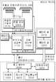
도 2는 상기 실시예의 전체적인 구조를 개략적으로 설명하는 블럭도이다.Fig. 2 is a block diagram schematically illustrating the overall structure of the embodiment.
도 3은 본 발명의 또다른 실시예에 따른 배터리 팩 장치를 포함하는 휴대폰의 전체적인 구성을 개략적으로 도시한 블럭도이다.3 is a block diagram schematically showing the overall configuration of a mobile phone including a battery pack device according to another embodiment of the present invention.
<도면의 주요부분에 대한 부호의 설명><Description of the symbols for the main parts of the drawings>
100 : 제어부 300 : 배터리 셀100: control unit 300: battery cell
500 : 부가회로부 700 : 검출부500: additional circuit 700: detector
900 : 초음파 진동자 전극900: Ultrasonic Oscillator Electrode
200 : 키패드 400 : 표시부200: keypad 400: display unit
600 : 무선 통신부 800 : 제 2 제어부600: wireless communication unit 800: second control unit
본 발명은 휴대용 단말기의 배터리 팩에 관한 것이며, 특히 이동 통신 단말기에 적용될 수 있는 부가 기능, 예를 들면 노래방, 질병 진단, 피부 미용 등의 기 능에 필요한 전용 회로를 내장하며, 이동 통신 단말기 본체와 데이터를 교환하는 다기능 배터리 팩에 관한 것이다. 본 발명은 예를 들면 휴대폰이나 개인 휴대 단말기(PDA), 나아가 MP3 플레이어와 같은 자체 제어 기능을 가지며 배터리 팩이 착탈되도록 결합되는 휴대용 단말기에 적용 가능하다.BACKGROUND OF THE INVENTION 1. Field of the Invention The present invention relates to a battery pack of a portable terminal. In particular, the present invention relates to a battery pack of a portable terminal, and includes a dedicated circuit necessary for functions such as karaoke, disease diagnosis, skin care, and the like. Relates to a multifunctional battery pack. The present invention is applicable to a portable terminal having a self-control function such as, for example, a mobile phone, a personal digital assistant (PDA), or even an MP3 player, and which is detachably coupled to a battery pack.
이동 통신 단말기의 기능을 확장하기 위하여 배터리 팩에 추가적인 옵션 회로를 내장시키는 아이디어가 제시되어 왔다. 1997. 10. 14. 자 간행된 일본특개평9-270836호에는 이동통신 단말기에 착탈 가능하게 결합되는 배터리 팩에 내장된 라디오 회로로 구현된 부가 장치를 개시하고 있다. 또한 김태진 등에 의해 출원되어 2001. 3. 15.자 공개된 공개특허공보 2001-19664호에는 이동통신 단말기의 배터리 팩에 MP3 코덱과 플래시 메모리 모듈을 내장하고 이동통신 단말기의 사용자 인터페이스를 이용해 제어하는 오디오 재생장치에 대해 기재하고 있다.The idea of incorporating additional option circuits into the battery pack has been proposed to extend the functionality of mobile communication terminals. Japanese Patent Laid-Open No. 9-270836, published October 14, 1997, discloses an additional device implemented with a radio circuit embedded in a battery pack detachably coupled to a mobile communication terminal. In addition, Korean Patent Application Publication No. 2001-19664 filed by Kim Tae-jin and published March 15, 2001, includes an MP3 codec and a flash memory module in a battery pack of a mobile communication terminal, and controls audio using a user interface of the mobile communication terminal. The playback apparatus is described.
이와 관련하여 본 출원인은 휴대용 통신 단말기와 결합되어 저주파 치료, 초음파 미용 치료, 생체 임피던스 측정 등을 지원할 수 있는 배터리 팩 장치를 2002. 9. 3.자로 특허출원 제2002-53004호, 2002-52996호, 2002-52995호, 2002-52994호로 출원한 바 있다. 이 장치들은 배터리 팩 내에 필요한 프로브들과 관련 구동회로를 내장하고 이동 통신 단말기 본체와 통신하며, 이동 통신 단말기에서 실행되는 응용 프로그램에 의해 배터리 팩 내의 회로를 제어하여 전술한 기능을 지원한다.In this regard, the present applicant has a battery pack device which can be combined with a portable communication terminal to support low frequency treatment, ultrasound cosmetic treatment, bioimpedance measurement, etc. , 2002-52995, 2002-52994. These devices incorporate the necessary probes and associated driving circuits in the battery pack, communicate with the mobile communication terminal body, and control the circuits in the battery pack by an application program executed in the mobile communication terminal to support the above-mentioned functions.
이 같은 다기능 복합 배터리 팩 장치에 있어서 실제 제품을 구현하는 과정에서 다음과 같은 문제점이 도출되었다. 즉, 대부분의 이동통신 단말기는 그 내부에 배터리의 수명을 연장하고 배터리 자체를 보호하기 위하여 전원 관리 기능을 지원 한다. 이 기능은 단말기의 동작 상태에 따라 메인 제어부와 주변 장치들로 공급되는 전원 레벨이나 클럭을 조절하여 소모 전력을 달리하도록 조작하는 전원 절약 기능을 포함한다. 그러나 복합 배터리 팩 장치의 경우 이 같은 전원 절약 기능의 제어를 받을 수 없어 전원 관리 상의 문제점이 있었다. 즉, 배터리 팩 내의 회로는 단말기 본체에서 요구할 경우 언제든지 고유한 부가 기능을 위해 활성화될 수 있어야 하므로 전원을 과다하게 소모하는 문제가 있다.The following problems were derived from the actual product implementation in such a multifunctional composite battery pack device. That is, most mobile communication terminals support a power management function to extend the life of the battery and to protect the battery itself. This function includes a power saving function for controlling the power level or clock supplied to the main controller and the peripheral devices to vary the power consumption according to the operation state of the terminal. However, in the case of the composite battery pack device, such a power saving function cannot be controlled, which causes power management problems. That is, the circuit in the battery pack has to be activated for a unique additional function at any time when the terminal body requires, there is a problem that consumes excessive power.
본 발명은 이 같은 문제점을 해결하기 위한 것으로, 본 발명은 자체의 전원 소모를 효율적으로 관리할 수 있는 부가 기능을 갖는 다기능 복합 배터리 팩 장치를 제공하는 것을 목적으로 한다.The present invention is to solve such a problem, it is an object of the present invention to provide a multifunctional composite battery pack device having an additional function that can efficiently manage its own power consumption.
상기 목적을 달성하기 위한 본 발명의 일 양상에 따른 배터리 팩 장치는 :Battery pack device according to an aspect of the present invention for achieving the above object is:
휴대폰과 인터페이스하는 통신 인터페이스부와, 휴대폰으로 전원을 공급하는 전원 공급 단자와, 상기 전원 공급 단자로 직류 전원을 공급하는 적어도 하나의 배터리 셀과, 메인 프로그램이 저장되는 메모리와, 단말기 본체측에 부가 기능을 제공하는 부가 회로부와, 상기 메인 프로그램에 따라 제어되며, 상기 통신 인터페이스부로부터의 조작 데이터에 따라 상기 부가 회로부를 제어하는 부가기능 제공부를 포함하는 제어부를 포함하는 휴대용 단말기의 배터리 팩 장치에 있어서,A communication interface for interfacing with the mobile phone, a power supply terminal for supplying power to the mobile phone, at least one battery cell for supplying DC power to the power supply terminal, a memory for storing a main program, and a terminal main body side A battery pack device of a portable terminal comprising a control unit including an additional circuit unit for providing a function, and an additional function control unit controlled according to the main program and controlling the additional circuit unit in accordance with operation data from the communication interface unit. ,
상기 장치가 상기 전원 공급 단자로 제공되는 전력량을 검출하는 검출부를 더 포함하고, 상기 제어부가 상기 검출부로부터 검출된 전력량에 따라 배터리 팩의 소모 전력 수준을 연동하여 제어하는 전원제어부;를 더 포함하는 것을 특징으로 한다.The apparatus further includes a detection unit for detecting the amount of power provided to the power supply terminal, the control unit further comprises a power control unit for controlling the power consumption level of the battery pack in accordance with the amount of power detected from the detection unit; It features.
이 같은 양상에 따라 본 발명은 본체에 착탈식으로 결합되며 부가기능을 제공하기 위한 회로를 포함하는 배터리 팩 장치에 있어서 본체측의 전력 관리 모드에 연동되어 배터리 팩 측의 부가 기능 제공을 위한 회로도 전력 소모를 관리해줌으로써 사용자의 사용 상태에 맞추어 효율적으로 전력을 관리할 수 있는 작용효과가 있다.According to this aspect, the present invention is a battery pack device detachably coupled to the main body and includes a circuit for providing an additional function, the circuit diagram for providing additional functions on the battery pack side in conjunction with the power management mode of the main body side power consumption By managing the power, the power can be efficiently managed according to the user's use status.
나아가 상기 양상에 따른 본 발명은 본체측에서 전력 관리 모드를 배터리 팩 측으로 알려주는 것이 어려운 경우에도 배터리 팩 측 자체에서 본체측으로 공급하는 전력을 검출함으로써 자체 소모 전력을 효율적으로 관리하는 것이 가능하다.Furthermore, according to the present invention, even when it is difficult to inform the battery pack side of the power management mode from the main body side, it is possible to efficiently manage its own power consumption by detecting the power supplied from the battery pack side itself.
본 발명의 또다른 양상에 따른 배터리 팩 장치는 :A battery pack device according to another aspect of the present invention is:
휴대폰과 인터페이스하는 통신 인터페이스부와, 휴대폰으로 전원을 공급하는 전원 공급 단자와, 상기 전원 공급 단자로 직류 전원을 공급하는 적어도 하나의 배터리 셀과, 메인 프로그램이 저장되는 메모리와, 단말기 본체측에 부가 기능을 제공하는 부가 회로부와, 상기 메인 프로그램에 따라 제어되며, 상기 통신 인터페이스부로부터의 조작 데이터에 따라 상기 부가 회로부를 제어하는 부가기능 제공부를 포함하는 제어부를 포함하는 휴대용 단말기의 배터리 팩 장치에 있어서,A communication interface for interfacing with the mobile phone, a power supply terminal for supplying power to the mobile phone, at least one battery cell for supplying DC power to the power supply terminal, a memory for storing a main program, and a terminal main body side A battery pack device of a portable terminal comprising a control unit including an additional circuit unit for providing a function, and an additional function control unit controlled according to the main program and controlling the additional circuit unit in accordance with operation data from the communication interface unit. ,
상기 제어부가 상기 통신 인터페이스부로부터 수신한 본체측 전력 관리 모드에 연동하여 배터리 팩 측의 회로들의 소모 전력 수준을 제어하는 전원제어부를 더 포함하는 것을 특징으로 한다.The controller may further include a power controller configured to control power consumption levels of circuits on the battery pack side in association with the main body side power management mode received from the communication interface unit.
상기 양상에 따라 본 발명은 휴대용 단말기측에서 배터리 팩 측의 요구에 따라 현재의 전력 관리 모드를 알려주고, 그에 따라 배터리 팩 측에서 자체의 전력 관리 모드도 연동하여 제어함으로써 배터리 팩 측에서 전력 관리를 위한 별도의 부가 회로를 추가하지 않고도 효율적으로 소모 전력을 관리하는 것이 가능하다.According to the above aspect, the present invention informs the current power management mode according to the request of the battery pack at the portable terminal side, and accordingly controls the power management mode of the battery pack side by interlocking for power management at the battery pack side. It is possible to manage power consumption efficiently without adding additional circuitry.
이하에서는 전술한, 그리고 추가적인 본 발명의 양상들을 첨부된 도면을 참고하여 기술되는 바람직한 실시예들을 통하여 당업자가 용이하게 이해하고 재현할 수 있도록 상세히 설명하기로 한다.DETAILED DESCRIPTION Hereinafter, the foregoing and further aspects of the present invention will be described in detail with reference to the accompanying drawings so that those skilled in the art can easily understand and reproduce.
도 1은 본 발명의 제 1 실시예에 따른 미용 치료 장치의 외관을 개략적으로 도시한 도면이다.1 is a view schematically showing the appearance of a cosmetic treatment device according to a first embodiment of the present invention.
이 실시예는 초음파 치료 기능을 가진 휴대폰에 관한 것이다. 그러나 이는 예시적인 목적으로 제시된 것이며, 본 발명은 이에 한정되지 않고 자체의 부가 기능을 제어하기 위한 제어부를 포함하고 추가적인 부가 회로를 포함하는 많은 배터리 팩 장치, 예를 들면 종래기술에서 본 출원인이 출원한 것으로 언급한 특허출원 제2002-53004호, 2002-52996호, 2002-52995호, 2002-52994호나 또는 종래기술에서 제시된 MP3 기능을 가진 배터리 팩 장치 등에 널리 적용될 수 있다.This embodiment relates to a mobile phone having an ultrasonic therapy function. However, this is presented for exemplary purposes, and the present invention is not limited thereto, and many battery pack devices including a control unit for controlling its own additional functions and including additional additional circuits, for example, those filed by the present applicant in the prior art. It is widely applicable to the patent applications 2002-53004, 2002-52996, 2002-52995, 2002-52994, or the battery pack device having the MP3 function described in the prior art.
이 실시예는 배터리 팩의 표면에 초음파 치료를 위한 전극이 제공된다. 사용자는 이동 통신 단말기에서 초음파 치료 메뉴를 선택하고, 적절한 레벨을 선택한 다음 시작을 명령한다. 이후에 초음파 전극을 안면과 같은 피부에 접촉시키면 접촉을 검출하여 이 전극에 초음파가 제공된다.This embodiment is provided with an electrode for ultrasound therapy on the surface of the battery pack. The user selects an ultrasound therapy menu on the mobile communication terminal, selects an appropriate level, and commands to start. Subsequently, when the ultrasonic electrode comes into contact with the skin such as the face, the contact is detected and ultrasonic waves are provided to the electrode.
도 2는 상기 실시예의 전체적인 구조를 개략적으로 설명하는 블럭도이다.Fig. 2 is a block diagram schematically illustrating the overall structure of the embodiment.
도시된 바와 같이 본 실시예는 휴대폰 본체(10)와 인터페이스하는 통신 인터페이스부(30)와, 휴대폰 본체(10)로 전원을 공급하는 전원 공급 단자(50)와, 상기 전원 공급 단자(50)로 직류 전원을 공급하는 적어도 하나의 배터리 셀(310, 330)과, 상기 전원 공급 단자(50)로 제공되는 전력을 검출하는 검출부(700)와, 메인 프로그램이 저장되는 메모리(150)와, 단말기 본체측에 부가 기능을 제공하는 부가 회로부(500)와, 상기 메인 프로그램에 따라 제어되며, 상기 통신 인터페이스부로부터의 조작 데이터에 따라 상기 부가 회로부(500)를 제어하는 부가기능 제공부(110)와 상기 검출부(700)로부터 검출된 전력에 따라 배터리 팩(20) 측의 회로들의 소모 전력 수준을 연동하여 제어하는 전원제어부(100)를 포함하는 제어부(100)를 포함한다.As shown in the present embodiment, the communication interface 30 to interface with the mobile phone main body 10, the power supply terminal 50 for supplying power to the mobile phone main body 10, and the power supply terminal 50 At least one
바람직한 일 실시예에 있어서, 상기 휴대폰 본체(10)에는 가상 머신(virtual machine) 기반으로 실행되는 응용프로그램이 탑재되어 초음파 치료 기능을 제어한다. 제 2 제어부(800)는 휴대폰에 통상적으로 탑재되는 복합 제어 칩, 예를 들면 CDMA 방식의 휴대폰의 경우 퀄컴사의 MSM 계열 칩에 포함된 범용 마이크로프로세서에 해당한다. 휴대폰 본체(10)는 부가 기능에도 필요한 사용자 조작 명령을 입력하는 키패드(200)와, 조작 정보 및 결과 데이터가 표시되는 표시부(400)를 구비한다. 추가적으로 자체 소모 전력을 관리하는 하드웨어와 소프트웨어를 포함하는 전원제어부(820)를 포함한다. 이 같은 휴대폰 본체(10)의 하드웨어적인 구성은 본원발명의 출원일 이전에 널리 알려진 것이며, 가상 머신 기반의 응용프로그램 관련 기술도 이미 개발자 툴이 보급되어 당업자라면 필요에 따라 구현할 수 있다.In a preferred embodiment, the mobile phone main body 10 is equipped with an application running on a virtual machine (virtual machine) to control the ultrasound treatment function. The
배터리 팩(20)은 통상적인 배터리셀들(310, 330)을 다수개 포함하며, 이들로부터 직류 전원을 전원공급단자(50)를 통해 본체(10)측으로 공급한다. 본 발명의 일 실시예에 따른 배터리 팩(20)은 통상적인 전원공급단자(50)외에 통신 인터페이스(30)를 구비한다. 바람직한 실시예에 있어서 전원공급단자(50)와 통신 인터페이스(30)는 물리적으로 동일한 커넥터로 구현되어 휴대폰 본체(10)에 배터리 팩(20)을 결합할 때 배터리 팩의 결합면과 본체측의 대응되는 결합면에서 전기적으로 접속되도록 설치될 수 있다. 본 실시예에 있어서 통신 인터페이스(30)는 USB 직렬 통신 프로토콜로 구현된다. 그러나 본 발명은 이에 한정되지 않으며 휴대폰 본체가 지원하는 다양한 외부 인터페이스로 확장될 수 있다.The battery pack 20 includes a plurality of
본 발명의 특징적인 양상에 따라 배터리 셀(310, 330)들로부터 본체로 공급되는 전력을 검출하기 위하여 검출부(700)가 제공된다. 이 검출부(700)는 예를 들면 공급되는 전류를 검출하기 위한 전류계(710)를 포함한다. 전압이 거의 일정하게 유지될 때 공급되는 전류량은 본체측의 동작 상태를 간접적으로 파악할 수 있는 유력한 근거가 된다. 검출부(700)는 추가로 전압계(730)를 포함할 수 있는데 이는 배터리 셀(310,330)의 충방전 상태를 체크하는 기초가 될 수 있다.According to a characteristic aspect of the present invention, a detector 700 is provided to detect power supplied from the
부가 회로부(500)는 배터리 팩(20)이 지원하는 부가 기능의 종류에 따라 다양한 회로들을 포함할 수 있으며, 아날로그 회로 및/또는 디지탈 회로를 포함한다. 본 실시예에 있어서, 부가 회로부(500)는 제 1 제어부(100)의 제어 신호에 따라 초음파 구동 신호를 발생하는 초음파 구동부(510)와, 이 초음파 구동부(510)의 구동 신호에 따라 압전 세라믹 진동자의 양면에 밀착하여 일체로 형성된 전극에 전계를 인가하여 초음파 진동을 발생하는 초음파 진동자 전극(910, 930)을 포함한다. 또한 초음파 구동부(510)는 피부에 접촉하지 않았을때의 진동은 불필요한 열을 발생하고 전력 소모의 원인이 되므로 이를 차단하기 위해 초음파 진동자 전극(910,930)에의 피부 접촉을 검출하는 회로로 예를 들면 온도 센서(530)를 포함한다. 이 같은 초음파 구동 회로와 진동자를 포함한 초음파 피부 미용 회로는 본 발명의 출원일 이전에 다양한 형태가 공지되어 있으므로 상세한 설명은 생략한다.The additional circuit unit 500 may include various circuits according to the type of additional functions supported by the battery pack 20, and may include an analog circuit and / or a digital circuit. In the present exemplary embodiment, the additional circuit unit 500 may include an
제 1 제어부(100)는 이 같은 배터리 팩(20)의 회로들을 총괄 제어하며, 바람직한 실시예에 있어서 검출부(700)로부터의 아날로그 신호를 디지탈로 변환하는 복수 채널의 아날로그-디지탈 변환기와, 필요한 코어 프로그램이 저장될 수 있는 EEPROM 과, 통신 인터페이스(100)를 위한 인터페이스회로를 원칩으로 내장하는 범용 마이크로프로세서인 것이 바람직하다. 이 같은 마이크로프로세서는 다양한 제조사에 의해 상업적으로 입수 가능하다.The first control unit 100 collectively controls the circuits of the battery pack 20, and in a preferred embodiment, a multi-channel analog-to-digital converter for converting the analog signal from the detection unit 700 into digital and a necessary core. It is preferable that the microprocessor is a general-purpose microprocessor that integrates an EEPROM into which a program can be stored and an interface circuit for the communication interface 100 in one chip. Such microprocessors are commercially available from various manufacturers.
메모리(150)는 제 1 제어부(100)와 동일한 칩에 포함될 수 있으며, 배터리 팩(20)의 제어에 필요한 메인 프로그램이 저장된다. 이 메인 프로그램은 부가 기능을 제공하는데 필요한 프로그램 로틴과, 본 발명의 특징적인 양상인 전원 제어 기능을 제공하는데 필요한 프로그램 루틴을 포함한다. 이러한 프로그램을 실행함으로써 제 1 제어부(100)는 예를 들면 초음파 미용 치료, 저주파 치료, MP3 음악 재생, 노래방 기능 등을 제공하는 부가 기능 제공부(110)와, 전원 관리를 제어하는 전원 제어부(130)로 구성될 수 있다.The
이하에서는 제 2 제어부(800)를 제어하는 응용 프로그램과, 메모리(150)에 저장되어 제 1 제어부(100)를 제어하는 메인 프로그램의 처리 내용을 설명한다. 먼저 휴대폰 본체(10)측 응용 프로그램은 키패드(200)를 스캔하여 부가 기능이 선택되면, 가능한 부가 기능의 목록을 표시부(400)로 표시한다. 이후에 키패드(200)를 통해 초음파 피부 미용 기능이 선택되면 통신 인터페이스(30)를 통해 배터리 팩(20)측에 초음파 피부 미용 기능의 실행을 요청한다.Hereinafter, the processing contents of the application program controlling the
제 1 제어부(100)는 이 요청을 접수하면, 부가 기능을 제공하는 루틴을 로딩하든가 또는 그 루틴의 시작으로 실행을 분기(branch)하여 부가기능 제공부(110)의 기능을 처리한다. 먼저 온도 센서(530)를 주기적으로 읽어 초음파 진동자 전극(910,930)이 피부에 접촉되었다고 판단되면 초음파 구동부(510)로 구동 개시 신호를 출력한다. 아날로그 발진회로와 증폭회로를 포함하는 초음파 구동부(510)는 이에 의해 발진을 개시하고 양면의 전극에 이 구동 전압을 인가받은 초음파 진동자 전극(910, 930)은 초음파 진동을 하게 된다.When the first control unit 100 receives the request, the first control unit 100 processes a function of the additional
한편, 부가 기능을 제공하고 있지 않은 경우에 전원 제어부(130)가 실행된다. 전원 제어부(130)는 제 1 제어부(100)가 전력 소모가 큰 모드인 활성 상태나 전력 소모를 최소로 하는 비활성 상태, 심지어 거의 전원이 소모되지 않는 휴면 상태(suspended mode)에서도 주기적으로 실행된다. 전원 제어부(130)는 검출부(700)의 전류계(710)를 읽어 전원공급단자(50)를 통해 휴대폰 본체(10)측으로 공급되는 전류량을 측정한다. 전류량이 일정치 이하이면 휴대폰이 비활성 상태이고 따라서 배터리 팩(20)에 포함된 부가기능이 사용될 가능성이 없으므로 예를 들면, 배터리 팩(20)측 회로들에게 공급되는 전원을 차단하여 자체 전력 소모를 줄인다.On the other hand, when the additional function is not provided, the
휴대폰은 비활성 상태에서도 주기적으로 기지국과의 통신을 하여 전력 소모가 변화되므로 이 같은 전력 소모의 변화를 정확하게 검출하기 위해서는 현재의 배터리의 충방전 상태와 전류량을 함께 고려하여 판단하는 것이 바람직하다. 이에 따라 바람직한 일 실시예에 있어서 배터리의 충방전 상태를 검출하기 위해 검출부(700)는 전압계(730)를 포함한다.Even when the mobile phone is inactive, the communication with the base station periodically changes the power consumption. Therefore, in order to accurately detect such a change in the power consumption, it is preferable to consider the current state of charge and discharge of the battery. Accordingly, in one preferred embodiment, the detector 700 includes a
전원 제어부(130)가 전원을 관리하는 모드는 간단하게는 부가 회로의 전원을 완전히 차단하거나 100% 공급하는 두 가지 모드가 가능하다. 이를 위해 초음파 구동부(510)의 전체 블럭의 전력을 공급하는 전력 라인이 예를 들면 아날로그 스위치를 통해 공급되고, 제 1 제어부가 이 스위치를 조작하여 전원 공급을 제어할 수 있다. 또한 많은 통합 마이크로프로세서가 내장된 주변장치회로에 대한 전원 관리 모드를 지원하므로 이들을 소프트웨어적인 프로그래밍에 의해 추가로 제어함으로써 좀 더 효율적으로 전력소모를 관리할 수 있다. 더 나아가 마이크로프로세서 자체의 공급 클럭을 조절하여 자체 전력 소모를 관리함에 의해 보다 더 효율적으로 전력소모를 관리할 수 있다. 이 같은 주변장치 및 마이크로프로세서의 전원 관리 기술 자체는 본 발명의 출원일 이전에 당업계에 공지된 것이므로 상세한 설명은 생략한다.There are two modes in which the
도 3은 본 발명의 또다른 실시예에 따른 배터리 팩 장치를 포함하는 휴대폰의 전체적인 구성을 개략적으로 도시한 블럭도이다. 제 1 실시예와 동일하거나 대응되는 구성요소에는 동일한 도면부호가 부여되었다.3 is a block diagram schematically showing the overall configuration of a mobile phone including a battery pack device according to another embodiment of the present invention. The same reference numerals are assigned to the same or corresponding components as in the first embodiment.
본 실시예는 휴대용 단말기 본체(10)와 인터페이스하는 통신 인터페이스부(30)와, 휴대용 단말기 본체(10)로 전원을 공급하는 전원 공급 단자(50)와, 상기 전원 공급 단자(50)로 직류 전원을 공급하는 적어도 하나의 배터리 셀(310, 330)과, 메인 프로그램이 저장되는 메모리(150)와, 휴대용 단말기 본체 측에 부가 기능을 제공하는 부가 회로부(500)와, 상기 메인 프로그램에 따라 제어되며, 상기 통신 인터페이스부(30)로부터의 조작 명령에 따라 상기 부가 회로부를 제어하는 부가기능 제공부(110)를 포함하는 제어부(100)를 포함하는 휴대용 단말기의 배터리 팩 장치에 있어서, 상기 제어부(100)가 상기 통신 인터페이스부(30)로부터 수신한 본체측 전력 관리 모드 명령에 연동하여 배터리 팩 측의 회로들의 소모 전력 수준을 제어하는 전원제어부(130)를 더 포함하는 것을 특징으로 한다.In the present embodiment, a communication interface 30 for interfacing with the portable terminal main body 10, a power supply terminal 50 for supplying power to the portable terminal main body 10, and a DC power supply to the power supply terminal 50 are provided. At least one battery cell (310, 330) for supplying the memory, the
본 실시예는 제 1 실시예와 달리 공급 전력을 검출부로부터 검출하여 판단하지 않고 휴대폰 본체(10)측에 실행되는 프로그램의 판단에 의존하여 제어한다. 즉, 휴대폰 본체(10) 측에는 항상 실행되는 응용 프로그램이 있어서 주기적으로 또는 이벤트가 발생할 때마다 본체측의 전력 관리 모드를 파악한다. 전력 관리 모드가 바뀌면 배터리 팩(20)측에도 동일하거나 대응되는 전력 관리 모드로 변경될 수 있도록 통신 인터페이스(30)를 통해 전력 관리 모드를 바꿀 것을 명령하는 명령 데이터를 송신한다. 이에 따라 제 1 제어부(100)에 포함된 전원 제어부(130) 모듈은 자체 전력 관리를 위한 하드웨어, 예를 들면 제 1 실시예에서 언급한 아날로그 스위치를 제어하여 부가회로부(500)의 공급 전력을 차단하고 자체 클럭을 조절하고 집적된 주변장치 회로들의 공급 전력도 연동하여 차단한다.Unlike the first embodiment, the present embodiment does not detect and determine the supply power from the detection unit, and controls the control unit depending on the determination of the program executed on the cellular phone main body 10 side. That is, the mobile phone main body 10 has an application program that is always executed so as to grasp the power management mode of the main body side periodically or whenever an event occurs. When the power management mode is changed, command data is transmitted to the battery pack 20 to instruct the power management mode to be changed through the communication interface 30 so as to be changed to the same or corresponding power management mode. Accordingly, the
이상에서 상세히 기술한 바와 같이 본 발명은 본체측의 전력 관리 모드에 연동하여 배터리 팩에 포함된 회로들의 소모 전력을 제어함으로써 배터리 팩에 부가 기능이 포함됨에 따라 배터리 연속 사용시간이 단축되는 문제점을 매우 효율적으로 완화하였다. As described in detail above, the present invention controls the power consumption of circuits included in the battery pack in conjunction with the power management mode of the main body, thereby reducing the continuous battery use time as additional functions are included in the battery pack. Efficiently relaxed
더 나아가 본 발명은 본체측에 공급되는 전력을 간접적으로 측정하거나 또는 본체측에 포함된 응용 프로그램으로부터 전달받은 본체측 동작 모드에 다라 배터리 팩에 포함된 회로들의 소모 전력을 제어함으로써 본체측과 연동시키는 매우 손쉽고 간단한 기술적 구성을 제시하였다.Furthermore, the present invention is indirectly measured by indirectly measuring the power supplied to the main body side or by controlling the power consumption of circuits included in the battery pack according to the main body side operation mode received from an application program included in the main body side. The technical configuration is very easy and simple.
본 발명은 제시된 실시예를 중심으로 설명되었으나 당업자라면 본 발명의 범주를 벗어남이 없이 매우 다양한 변형예들이 가능하다는 것은 자명하다. 따라서 본 발명은 이 같은 변형예들을 포괄하도록 의도된 특허청구범위에 의해서 해석되어질 것이다.Although the invention has been described with reference to the examples presented, it will be apparent to those skilled in the art that a wide variety of modifications are possible without departing from the scope of the invention. Accordingly, the invention will be construed by the claims, which are intended to cover such modifications.
Claims (4)
Translated fromKoreanPriority Applications (5)
| Application Number | Priority Date | Filing Date | Title |
|---|---|---|---|
| KR1020020065297AKR100673603B1 (en) | 2002-10-24 | 2002-10-24 | Multifunction Composite Battery Pack Unit |
| US10/532,343US7426405B2 (en) | 2002-10-24 | 2003-10-20 | Battery pack of a mobile communication terminal and connector for connecting the battery pack with the terminal |
| JP2005501581AJP2006510330A (en) | 2002-10-24 | 2003-10-20 | Functional battery pack for mobile communication terminal and connector for connecting the same |
| AU2003273080AAU2003273080A1 (en) | 2002-10-24 | 2003-10-20 | Battery pack of a mobile communication terminal and connector for connecting the battery pack with the terminal |
| PCT/KR2003/002194WO2004038943A1 (en) | 2002-10-24 | 2003-10-20 | Battery pack of a mobile communication terminal and connector for connecting the battery pack with the terminal |
Applications Claiming Priority (1)
| Application Number | Priority Date | Filing Date | Title |
|---|---|---|---|
| KR1020020065297AKR100673603B1 (en) | 2002-10-24 | 2002-10-24 | Multifunction Composite Battery Pack Unit |
Publications (2)
| Publication Number | Publication Date |
|---|---|
| KR20040036325A KR20040036325A (en) | 2004-04-30 |
| KR100673603B1true KR100673603B1 (en) | 2007-01-23 |
Family
ID=37334905
Family Applications (1)
| Application Number | Title | Priority Date | Filing Date |
|---|---|---|---|
| KR1020020065297AExpired - Fee RelatedKR100673603B1 (en) | 2002-10-24 | 2002-10-24 | Multifunction Composite Battery Pack Unit |
Country Status (1)
| Country | Link |
|---|---|
| KR (1) | KR100673603B1 (en) |
Citations (2)
| Publication number | Priority date | Publication date | Assignee | Title |
|---|---|---|---|---|
| JP2001189785A (en)* | 1999-10-20 | 2001-07-10 | Mitsubishi Electric Corp | Battery pack for mobile phone device and mobile phone equipped with the battery pack |
| KR200279844Y1 (en)* | 2002-02-09 | 2002-07-02 | (주)이프 컴 | Personal digital assistant with cellular phone |
- 2002
- 2002-10-24KRKR1020020065297Apatent/KR100673603B1/ennot_activeExpired - Fee Related
Patent Citations (2)
| Publication number | Priority date | Publication date | Assignee | Title |
|---|---|---|---|---|
| JP2001189785A (en)* | 1999-10-20 | 2001-07-10 | Mitsubishi Electric Corp | Battery pack for mobile phone device and mobile phone equipped with the battery pack |
| KR200279844Y1 (en)* | 2002-02-09 | 2002-07-02 | (주)이프 컴 | Personal digital assistant with cellular phone |
Also Published As
| Publication number | Publication date |
|---|---|
| KR20040036325A (en) | 2004-04-30 |
Similar Documents
| Publication | Publication Date | Title |
|---|---|---|
| JP2747971B2 (en) | Power supply device for portable information processing equipment and driving method thereof | |
| US8140129B2 (en) | Mobile phone terminal and communication system | |
| US7683578B2 (en) | Energy saving system | |
| GB2346477A (en) | Battery pack | |
| JP2006510330A (en) | Functional battery pack for mobile communication terminal and connector for connecting the same | |
| US20040119694A1 (en) | Wireless pointing device with forced power-off function | |
| US7343501B2 (en) | Power-saving device for notebook computer | |
| KR100673603B1 (en) | Multifunction Composite Battery Pack Unit | |
| US20120030487A1 (en) | Information processing apparatus and power control method | |
| KR100512736B1 (en) | Portable Computer | |
| JP5035800B2 (en) | Mobile device | |
| JP2004318629A (en) | Electronic device | |
| US6797419B2 (en) | Electronic apparatus powered by fuel cell having oxygen density detector | |
| KR100835315B1 (en) | Power control device and method for portable terminal | |
| CN103154855B (en) | There is the button of modulated bias voltage | |
| KR101070629B1 (en) | Power supply system for portable electronic devices and control method thereof | |
| JP6661105B1 (en) | Power control device | |
| KR20090024907A (en) | Portable charger with battery and control method | |
| KR20010003650A (en) | Apparatus for supplying of power in wireless telephone set and method thereof | |
| JP2004215464A (en) | Electronic apparatus | |
| CN223108315U (en) | A portable computer | |
| JP2012163446A (en) | Current measuring device | |
| CN214227881U (en) | Power supply circuit and instrument | |
| WO2010124479A1 (en) | User identification system and its power supply management method | |
| KR19990073937A (en) | Power control device of computer system and method |
Legal Events
| Date | Code | Title | Description |
|---|---|---|---|
| A201 | Request for examination | ||
| PA0109 | Patent application | St.27 status event code:A-0-1-A10-A12-nap-PA0109 | |
| PA0201 | Request for examination | St.27 status event code:A-1-2-D10-D11-exm-PA0201 | |
| R18-X000 | Changes to party contact information recorded | St.27 status event code:A-3-3-R10-R18-oth-X000 | |
| R18-X000 | Changes to party contact information recorded | St.27 status event code:A-3-3-R10-R18-oth-X000 | |
| PN2301 | Change of applicant | St.27 status event code:A-3-3-R10-R13-asn-PN2301 St.27 status event code:A-3-3-R10-R11-asn-PN2301 | |
| PN2301 | Change of applicant | St.27 status event code:A-3-3-R10-R13-asn-PN2301 St.27 status event code:A-3-3-R10-R11-asn-PN2301 | |
| R18-X000 | Changes to party contact information recorded | St.27 status event code:A-3-3-R10-R18-oth-X000 | |
| PN2301 | Change of applicant | St.27 status event code:A-3-3-R10-R13-asn-PN2301 St.27 status event code:A-3-3-R10-R11-asn-PN2301 | |
| PG1501 | Laying open of application | St.27 status event code:A-1-1-Q10-Q12-nap-PG1501 | |
| E902 | Notification of reason for refusal | ||
| PE0902 | Notice of grounds for rejection | St.27 status event code:A-1-2-D10-D21-exm-PE0902 | |
| AMND | Amendment | ||
| P11-X000 | Amendment of application requested | St.27 status event code:A-2-2-P10-P11-nap-X000 | |
| P13-X000 | Application amended | St.27 status event code:A-2-2-P10-P13-nap-X000 | |
| R17-X000 | Change to representative recorded | St.27 status event code:A-3-3-R10-R17-oth-X000 | |
| E601 | Decision to refuse application | ||
| PE0601 | Decision on rejection of patent | St.27 status event code:N-2-6-B10-B15-exm-PE0601 | |
| AMND | Amendment | ||
| E13-X000 | Pre-grant limitation requested | St.27 status event code:A-2-3-E10-E13-lim-X000 | |
| J201 | Request for trial against refusal decision | ||
| P11-X000 | Amendment of application requested | St.27 status event code:A-2-2-P10-P11-nap-X000 | |
| PJ0201 | Trial against decision of rejection | St.27 status event code:A-3-3-V10-V11-apl-PJ0201 | |
| R18-X000 | Changes to party contact information recorded | St.27 status event code:A-3-3-R10-R18-oth-X000 | |
| AMND | Amendment | ||
| E13-X000 | Pre-grant limitation requested | St.27 status event code:A-2-3-E10-E13-lim-X000 | |
| P11-X000 | Amendment of application requested | St.27 status event code:A-2-2-P10-P11-nap-X000 | |
| P13-X000 | Application amended | St.27 status event code:A-2-2-P10-P13-nap-X000 | |
| PE0801 | Dismissal of amendment | St.27 status event code:A-2-2-P10-P12-nap-PE0801 | |
| PB0901 | Examination by re-examination before a trial | St.27 status event code:A-6-3-E10-E12-rex-PB0901 | |
| B701 | Decision to grant | ||
| PB0701 | Decision of registration after re-examination before a trial | St.27 status event code:A-3-4-F10-F13-rex-PB0701 | |
| R18-X000 | Changes to party contact information recorded | St.27 status event code:A-3-3-R10-R18-oth-X000 | |
| GRNT | Written decision to grant | ||
| PR0701 | Registration of establishment | St.27 status event code:A-2-4-F10-F11-exm-PR0701 | |
| PR1002 | Payment of registration fee | St.27 status event code:A-2-2-U10-U11-oth-PR1002 Fee payment year number:1 | |
| PG1601 | Publication of registration | St.27 status event code:A-4-4-Q10-Q13-nap-PG1601 | |
| R18-X000 | Changes to party contact information recorded | St.27 status event code:A-5-5-R10-R18-oth-X000 | |
| LAPS | Lapse due to unpaid annual fee | ||
| PC1903 | Unpaid annual fee | St.27 status event code:A-4-4-U10-U13-oth-PC1903 Not in force date:20100118 Payment event data comment text:Termination Category : DEFAULT_OF_REGISTRATION_FEE | |
| R18-X000 | Changes to party contact information recorded | St.27 status event code:A-5-5-R10-R18-oth-X000 | |
| PC1903 | Unpaid annual fee | St.27 status event code:N-4-6-H10-H13-oth-PC1903 Ip right cessation event data comment text:Termination Category : DEFAULT_OF_REGISTRATION_FEE Not in force date:20100118 | |
| P22-X000 | Classification modified | St.27 status event code:A-4-4-P10-P22-nap-X000 | |
| P22-X000 | Classification modified | St.27 status event code:A-4-4-P10-P22-nap-X000 |