KR100672398B1 - Exhaust reflux vacuum cleaner - Google Patents
Exhaust reflux vacuum cleanerDownload PDFInfo
- Publication number
- KR100672398B1 KR100672398B1KR1019990067395AKR19990067395AKR100672398B1KR 100672398 B1KR100672398 B1KR 100672398B1KR 1019990067395 AKR1019990067395 AKR 1019990067395AKR 19990067395 AKR19990067395 AKR 19990067395AKR 100672398 B1KR100672398 B1KR 100672398B1
- Authority
- KR
- South Korea
- Prior art keywords
- suction
- port
- suction port
- vacuum cleaner
- air
- Prior art date
- Legal status (The legal status is an assumption and is not a legal conclusion. Google has not performed a legal analysis and makes no representation as to the accuracy of the status listed.)
- Expired - Fee Related
Links
Images


Classifications
- A—HUMAN NECESSITIES
- A47—FURNITURE; DOMESTIC ARTICLES OR APPLIANCES; COFFEE MILLS; SPICE MILLS; SUCTION CLEANERS IN GENERAL
- A47L—DOMESTIC WASHING OR CLEANING; SUCTION CLEANERS IN GENERAL
- A47L7/00—Suction cleaners adapted for additional purposes; Tables with suction openings for cleaning purposes; Containers for cleaning articles by suction; Suction cleaners adapted to cleaning of brushes; Suction cleaners adapted to taking-up liquids
- A47L7/04—Suction cleaners adapted for additional purposes; Tables with suction openings for cleaning purposes; Containers for cleaning articles by suction; Suction cleaners adapted to cleaning of brushes; Suction cleaners adapted to taking-up liquids for using the exhaust air for other purposes, e.g. for distribution of chemicals in a room, for sterilisation of the air
- A—HUMAN NECESSITIES
- A47—FURNITURE; DOMESTIC ARTICLES OR APPLIANCES; COFFEE MILLS; SPICE MILLS; SUCTION CLEANERS IN GENERAL
- A47L—DOMESTIC WASHING OR CLEANING; SUCTION CLEANERS IN GENERAL
- A47L5/00—Structural features of suction cleaners
- A47L5/12—Structural features of suction cleaners with power-driven air-pumps or air-compressors, e.g. driven by motor vehicle engine vacuum
- A47L5/22—Structural features of suction cleaners with power-driven air-pumps or air-compressors, e.g. driven by motor vehicle engine vacuum with rotary fans
- A47L5/28—Suction cleaners with handles and nozzles fixed on the casings, e.g. wheeled suction cleaners with steering handle
- A—HUMAN NECESSITIES
- A47—FURNITURE; DOMESTIC ARTICLES OR APPLIANCES; COFFEE MILLS; SPICE MILLS; SUCTION CLEANERS IN GENERAL
- A47L—DOMESTIC WASHING OR CLEANING; SUCTION CLEANERS IN GENERAL
- A47L9/00—Details or accessories of suction cleaners, e.g. mechanical means for controlling the suction or for effecting pulsating action; Storing devices specially adapted to suction cleaners or parts thereof; Carrying-vehicles specially adapted for suction cleaners
- A47L9/02—Nozzles
Landscapes
- Engineering & Computer Science (AREA)
- Mechanical Engineering (AREA)
- Nozzles For Electric Vacuum Cleaners (AREA)
Abstract
Translated fromKorean
Description
Translated fromKorean도 1 은 일반적인 업라이트형 청소기를 나타낸 사시도1 is a perspective view showing a general upright cleaner
도 2a 는 도 1의 Ⅰ-Ⅰ선을 단면하여 나타낸 상태도FIG. 2A is a cross-sectional view illustrating the line I-I of FIG. 1. FIG.
도 2b 는 도 1의 Ⅱ-Ⅱ선을 단면하여 나타낸 상태도2B is a cross-sectional view of the II-II line of FIG. 1.
도 3 은 일반적인 진공 청소기의 배기 환류방식을 개략적으로 나타낸 구성도3 is a schematic view showing an exhaust reflux method of a general vacuum cleaner
도 4 는 종래 배기 환류방식이 적용된 캐니스터형 청소기를 개략적으로 나타낸 사시도Figure 4 is a perspective view schematically showing a canister cleaner to which a conventional exhaust reflux method is applied
도 5 는 종래 배기 환류방식이 적용된 또 다른 형태의 청소기를 나타낸 단면도5 is a cross-sectional view showing another type of cleaner to which the conventional exhaust reflux method is applied.
도 6a, 6b는 본 발명 배기 환류방식을 채택한 진공 청소기의 흡입구체의 각 형태를 개략적으로 나타낸 상태도Figure 6a, 6b is a state diagram schematically showing each form of the inlet body of the vacuum cleaner employing the exhaust reflux method of the present invention
도 7a 는 본 발명에 따른 제1실시예를 나타낸 흡입구체의 개략적인 저면 사시도7A is a schematic bottom perspective view of a suction inlet port showing a first embodiment according to the present invention;
도 7b 는 본 발명에 따른 제1실시예를 나타낸 흡입구체의 종단면도Figure 7b is a longitudinal sectional view of the inlet port showing the first embodiment according to the present invention;
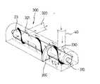
도 8a 는 본 발명에 따른 제2실시예를 나타낸 흡입구체의 개략적인 사시도8A is a schematic perspective view of a suction inlet port showing a second embodiment according to the present invention;
도 8b 는 본 발명에 따른 제2실시예를 나타낸 흡입구체의 종단면도8B is a longitudinal sectional view of the suction inlet port showing the second embodiment according to the present invention;
도 9 는 본 발명 제2실시예에 따른 면압분포를 개략적으로 나타낸 상태도9 is a state diagram schematically showing the surface pressure distribution according to the second embodiment of the present invention;
도 10 은 본 발명에 따른 제3실시예를 나타낸 흡입구체의 단면도10 is a cross-sectional view of a suction inlet showing a third embodiment according to the present invention.
도면의 주요부분에 대한 부호의 설명Explanation of symbols for main parts of the drawings
300. 흡입구체310. 흡입구300.
321. 공기 유입측320. 흡입유로321.
330. 분사구340. 차단판330.Brush
350. 구획판360. 압력강하부재350.
본 발명은 진공 청소기에 관한 것으로서, 더욱 상세하게는 진공 청소기 내에 집진이 이루어져 배출되는 공기를 재사용함으로써 실내 오염을 미연에 방지할 수 있도록 하는 배기 환류식 진공 청소기에 관한 것이다.The present invention relates to a vacuum cleaner, and more particularly, to a reflux reflux vacuum cleaner that can prevent indoor pollution by reusing air discharged by dust collection in a vacuum cleaner.
일반적으로 진공 청소기는 캐니스터형 진공 청소기(canister type vacuum cleaner)와 업라이트형 진공 청소기(up-right type vacuum cleaner)로 크게 대별할 수 있다.In general, vacuum cleaners can be roughly classified into canister type vacuum cleaners and up-right type vacuum cleaners.
이중, 업라이트형 청소기는 캐니스터형 청소기와는 달리 거실 등과 같은 광범위한 지역 특히, 양탄자가 깔려있는 장소에서 주로 사용되는 진공 청소기로써 그 전반적인 구조는 후술하는 바와 같다.Unlike the canister type cleaner, the upright cleaner is a vacuum cleaner mainly used in a wide area such as a living room, especially a place where a carpet is laid, and the overall structure thereof will be described later.
도시한 도 1 및 도 2a, 2b는 상기한 바와 같은 일반적인 업라이트형 진공 청소기를 도시한 도면으로써 크게 수직으로 세워지는 본체(10)와, 상기 본체의 하부 에 결합되어 먼지 등과 같은 각종 이물질이 흡입되도록 흡입구(21)가 형성된 흡입구체(20)와, 상기 본체의 상단에 연결되는 손잡이부(30)로 구성된다.1 and 2a and 2b illustrate a general upright type vacuum cleaner as described above, and a
이 때, 상기 본체 내 하부에는 팬(11)과 축결합된 모터(12)가 구비되어 진공력을 발생시킬 수 있도록 상기 팬을 회전시키게 되고, 상기 본체 내 상부에는 흡입구체(20)를 통해 흡입된 공기 및 각종 이물질을 집진할 수 있도록 집진봉투(13)가 구비되어 있으며, 상기 본체의 전방에는 본체 내로 흡입되어 집진봉투(13)를 통과한 공기가 상기 본체의 외부로 배출될 수 있도록 배출공(14)이 형성되어 있다.At this time, the lower part of the main body is provided with a
또한, 흡입구체(20)의 내부에는 상기 흡입구체의 흡입구(21)를 통해 흡입된 각종 먼지 및 공기의 유동을 안내하는 흡입유로(22)가 형성되어 있고, 상기 흡입유로의 일단은 본체(10) 내의 집진봉투(13)와 연통된 흡입호스(15)에 연결되어 있다.In addition, a
상기 흡입구체(20)의 흡입구(21)가 형성된 위치에는 그 저면을 통해 일부가 노출된 회전브러시(23)가 회전 가능하게 설치되어 있고, 상기 회전브러시는 본체(10)내에 구비된 모터(12)의 축(12b)에 벨트(16)로써 연결되어 구동력을 전달받게 된다.At the position where the
이 때, 상기 모터는 그 양측으로 축(12a)(12b)이 각각 돌출된 양축모터로 이루어져 있음에 따라 본체(10)내 구비된 팬(11) 및 벨트(16)로 각각 그 구동력을 전달할 수 있음은 이해 가능하다.At this time, the motor can transmit the driving force to the
이와 같이 구성된 업라이트형 진공 청소기의 작용에 관해 보다 구체적으로 설명하면 후술하는 바와 같다.The operation of the upright type vacuum cleaner configured as described above will be described below in more detail.
우선, 사용자의 필요에 따른 양탄자의 청소 수행을 원할 경우 손잡이부(30) 를 이용하여 본체(10)를 청소 수행 장소에 위치시킨다.First, when the user wants to perform cleaning of the carpet according to the user's needs, the
이후, 사용자는 상기 본체의 측면에 구비된 스위치(도시는 생략함)를 온(ON) 시킴으로써 본체(10)내 모터(12)를 구동시키게 된다.Thereafter, the user drives the
이에 따라 상기 모터와 축(12a) 결합된 팬(11)이 상기 모터의 구동력을 전달받아 회전하면서 흡입력을 발생시키게 되고, 이와 같은 흡입력은 본체(10) 내의 집진봉투(13)를 통과하여 흡입호스(15)로 전달된다.Accordingly, the
결국, 상기 흡입호스를 통해 전달되는 흡입력은 흡입구체(20)에 형성된 흡입구(21)를 통해 지면으로 전달됨으로써 상기 지면에 있는 각종 이물질의 청소 수행이 이루어지게 된다.As a result, the suction force transmitted through the suction hose is transferred to the ground through the
또한, 이 때에는 상기 흡입구에 설치된 회전브러시(23) 역시 본체(10) 내 구비된 모터(12)와 벨트(16)로써 연결되어 있음에 따라 상기 모터의 구동력을 전달받아 회전하게 된다.In addition, at this time, the
따라서, 흡입구체(20)의 전방에 위치된 회전브러시(23)가 회전을 행하면서 지면(양탄자 표면)을 쓸어내려 상기 지면에 붙어 있는 각종 이물질을 부유시키게 되고, 이와 같이 부유된 각종 이물질은 흡입구(21)를 통해 흡입유로(22) 내부로 유입된 후 흡입호스(15)를 통과하여 공기와 함께 집진봉투(13) 내로 유입된다.Accordingly, the
또한, 상기와 같이 집진봉투(13) 내로 유입된 공기 및 각종 이물질 중 그 입자가 비교적 큰 각종 이물질은 상기 집진봉투 내에 집진된 상태를 이루게 되고, 그 입자가 상당히 작은 공기만이 상기 집진봉투를 통과한 후 계속해서 본체(10)에 형성된 배출공(14)을 통해 외부로 배출된다.In addition, various foreign matters having relatively large particles among the air and various foreign matters introduced into the
결국, 전술한 바와 같은 과정이 연속적 및 반복적으로 수행되면서 청소가 이루어지게 되는 것이다.As a result, the cleaning as described above is carried out continuously and repeatedly.
하지만, 상기와 같은 종래 일반적인 업라이트형 진공청소기는 청소에 사용된 공기가 집진봉투(13)를 통과한 후 다시 실내로 배출되는 구조임에 따라 상기 집진봉투내 집진된 각종 이물질로부터 발생하는 냄새 및 각종 세균 역시 공기와 함께 집진봉투(13)를 통과함으로써 결국, 실내로 재 배출되는 문제점을 발생하게 되었다.However, according to the conventional general upright type vacuum cleaner as described above, since the air used for cleaning passes through the
이로 인해 실내 공기가 오염될 수 있음에 따라 사용자의 위생상 문제를 발생시키게 되어 결국, 사용자의 제품에 대한 신뢰성 저하가 유발되었다.As a result, the indoor air may be contaminated, which may cause a user's hygiene problem, resulting in a decrease in reliability of the user's product.
도시한 도 3은 이의 문제를 해결하기 위하여 배기 환류방식을 채택한 상태를 나타낸 업라이트형 청소기의 개략적인 내부 구성이이다.3 is a schematic internal configuration of an upright cleaner showing a state in which an exhaust reflux method is adopted to solve the problem.
즉, 본체에 형성된 배출공을 폐쇄하고, 모터(12)를 방열한 공기가 다시 흡입구체 측으로 그 유동이 이루어지도록 환류유로(40)를 형성한 것이다.That is, the
이 때, 상기 환류유로의 공기 배출이 이루어지는 측은 상기 흡입구체를 구성하는 흡입구의 전, 후방측 전 영역에 걸쳐 위치되도록 형성함으로써 상기 분사구를 통해 분사되는 배기공기의 재 흡입이 100% 이루어질 수 있도록 하고 있다.At this time, the side where the air is discharged to the reflux flow path is formed so as to be located over the entire area of the front and rear sides of the intake port constituting the intake port so that 100% re-suction of the exhaust air injected through the injection port can be made have.
이로 인해, 집진봉투(13)를 통과하면서 각종 냄새 및 세균등이 포함된 배기공기는 모터(12) 및 환류유로(40)를 순차적으로 통과하여 흡입구체(20)에 형성된 분사구(24)를 통해 배출되고, 이렇게 배출된 배기공기는 다시 흡입구체(20)의 흡입구(21)를 통해 전달되는 흡입력에 의해 재 흡입되어 계속적인 순환을 행하게 되는 것이다.Accordingly, the exhaust air containing various odors and bacteria while passing through the
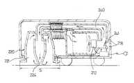
또한, 도시한 도 4는 캐니스터형 진공 청소기(canister type vacuum cleaner)의 개략적인 구성을 나타낸 사시도로써, 이 역시 배기 환류 방식을 채택하고 있음을 알 수 있다.In addition, Figure 4 is a perspective view showing a schematic configuration of a canister type vacuum cleaner (canister type vacuum cleaner), it can be seen that also adopts the exhaust reflux method.
즉, 본체(110)내 집진봉투(113)와 모터(112)를 각각 구비하고, 상기 모터를 통과한 공기가 다시 흡입구체(120)의 저면에 형성된 흡입구(121) 전방을 향하여 분사되도록 환류유로(140)를 형성하며, 상기 모터의 후방측인 본체의 후면에는 배기구(118)를 형성한 것이다.That is, the
이 때, 상기 흡입구체의 저면 전방측에는 흡입구(121)의 전체 흡입영역에 걸쳐 상기 환류유로(140)를 따라 유동하는 공기의 분사가 이루어지도록 분사구(124)를 형성함으로서 계속적인 공기의 순환이 이루어질 수 있도록 하고 있다.At this time, the bottom of the inlet port front side by forming the
이와 같은 구조에 의해 본체(110)내 집진봉투(113)를 통과한 공기 및 각종 냄새성분 혹은 세균등(이하, “배기공기”라 한다)이 청소기 외부로 직접 배출되지 않고 최초, 연통유로(114)를 통해 본체(110)내 모터(112)가 구비된 공간측으로 유동하여 모터(112)를 냉각시키게 되고, 계속해서 상기 모터를 냉각한 공기는 환류유로(140)의 안내를 받아 유동하면서 흡입구체(120)에 형성된 분사구(124)를 통해 흡입구체(120) 저면 전방측으로 분사된다.By such a structure, the air passing through the
이후, 상기와 같이 흡입구체(120) 저면으로 분사된 배기공기는 상기 흡입구체의 흡입구(121)를 통해 계속적으로 발생되고 있는 흡입력을 전달받아 상기 흡입구로 흡입되어 본체(110)내로 재 유입됨으로써 계속적인 공기의 환류가 이루어지게 되어 각종 오염물로부터 발생되는 냄새 및 세균등의 실내 배출이 방지될 수 있는 효과를 얻을 수 있다.Thereafter, the exhaust air injected to the bottom surface of the
도시한 도 5 는 미국특허 제5457848호에 기술된 발명으로써 이 역시 배기 환류방식을 채택한 구조로서, 이 때, 환류되는 공기의 20%는 새로운 공기와 교체 가능하도록 구성되어 있음과 함께 흡입효율을 향상시킨 구조를 이루고 있다.FIG. 5 is an invention described in US Pat. No. 5,574,48, which also adopts an exhaust reflux method, wherein 20% of the refluxed air is replaced with new air and improves suction efficiency. Structure.
즉, 환류유로(240)상에 별도의 바이패스 밸브(241)를 구비하여 흡입 효율에 따라 그 개폐정도가 적절히 조절되도록 구성하고, 상기 환류유로와 연결된 분사구(224) 위치는 흡입구체(220)의 흡입구(221)를 통해 돌출되어 흡입이 이루어지는 영역(S)내에 위치되도록 하고 있다.That is, a
따라서, 최초 청소기의 동작에 의해 공기 및 각종 먼지등의 유입이 이루어질 때에는 환류유로(240)상에 형성된 바이패스 밸브(241)가 폐쇄된 상태이므로 배기공기의 환류가 100% 이루어지게 된다.Therefore, when the air and various dusts are introduced by the operation of the first cleaner, the
또한, 상기와 같은 과정이 계속적으로 반복되는 과정에서 흡입구(221)측의 압력이 높아질 경우에는 상기 바이패스 밸브가 개방되어 일부의 배기공기는 개방된 배기구(218)를 통해 실내로 배출되고, 상기 배출된 공기의 양 만큼은 흡입구체(220)에 형성된 흡입구(221)를 통해 새로이 유입된다.In addition, when the pressure of the
이로 인해 모터(212)의 방열 효과는 유지시킬 수 있게 될 뿐만 아니라 배출되는 공기로 인한 실내 오염을 최대한 방지할 수 있게 되었다.Due to this, not only the heat dissipation effect of the
전술한 바와 같은 도 3, 도 4, 도 5의 각 형태는 환류되는 공기의 토출위치가 흡입구체의 흡입구 전체 영역에 걸쳐 위치되도록 형성함으로써 배기공기의 재 흡입이 원활히 이루어질 수 있도록 함과 함께 상기 배기공기의 분사력을 이용하여 지면에 있는 각종 먼지를 부유시킴으로써 보다 원활한 청소 효율을 얻고자 하고 있다.3, 4 and 5 as described above is formed so that the discharge position of the refluxed air is located over the entire area of the inlet port of the inlet port to facilitate the re-intake of the exhaust air and the exhaust By using the blowing force of air to float various dust on the ground to achieve a smoother cleaning efficiency.
하지만, 상기와 같은 강력한 배기공기의 분사력은 흡입영역에 위치되어 있는 각종 먼지등의 이물질을 강하게 부유시키거나 비산시키게 된다.However, the injection force of the powerful exhaust air as described above will strongly float or scatter foreign matters such as various dusts located in the suction area.
이 때에는 흡입구를 통해 흡입력이 발생되고 있음에 따라 상기 부유하는 각종 이물질의 일부는 상기 흡입구 내로 흡입되나 대부분은 흡입구체의 주변으로 비산되어 날림으로써 흡입영역을 벗어나게 되어 결국, 원활한 이물질의 흡입은 이루어지지 않게 된다.At this time, as the suction force is generated through the suction port, some of the floating various foreign matters are sucked into the suction port, but most of the foreign matters are scattered to the periphery of the suction port, thereby leaving the suction area, so that the smooth suction of foreign matters is not achieved. Will not.
즉, 분사구를 통해 분사되는 배기공기의 분사영역이 고압의 상태를 이루고 있고, 흡입구를 통해 흡입되는 흡입공기의 흡입영역은 저압의 상태를 이루고 있는 점을 감안 할 때 종래 일반적인 배기 환류방식을 채택한 청소기의 분사영역이 전체 흡입영역 내에 존재하기 때문에 흡입측의 (-)압과 분사측의 (+)압이 혼합되어 흡입구 전반에 걸쳐 진공압이 약해지게 되고, 이로 인해 흡입력이 급격히 저하될 수 밖에 없는 문제점을 발생하였다.That is, in view of the fact that the injection zone of the exhaust air injected through the injection port is in a high pressure state, and the suction zone of the suction air sucked through the inlet port is in a low pressure state, a cleaner using the conventional general exhaust reflux method is adopted. Since the injection zone of is in the entire suction zone, the negative pressure on the suction side and the positive pressure on the injection side are mixed, and the vacuum pressure is weakened throughout the suction port, so that the suction force is inevitably lowered. A problem has occurred.
즉, 흡입압력이 존재하는 영역내에 분사압력이 중첩되어 이 부분에서는 압력상쇄가 이루어지게 된 것이다.That is, the injection pressure is superimposed in the region where the suction pressure exists, so that the pressure cancellation is made in this portion.
이에 따라 모터의 토출측과의 압력차가 급격히 감소하게 되어 흡입구체의 저부인 지면에서는 진공압이 급격히 감소하게 되고, 이로 인해 흡입력이 저감되어 결국, 청소기의 성능저하를 유발시킴으로써 소비자의 불만을 초래하게 되는 문제점을 발생시켰다.As a result, the pressure difference with the discharge side of the motor is drastically reduced, and the vacuum pressure is drastically reduced on the ground, which is the bottom of the suction port. It caused a problem.
본 발명은 상기와 같은 종래의 문제점을 해결하기 위해 안출한 것으로서, 배기 환류식 진공 청소기의 흡입영역에서 각종 이물질이 비산됨을 방지하고, 각종 이물질의 흡입이 보다 원활히 이루어질 수 있도록 함과 동시에 위생적인 청소가 가능하도록 하는데 그 목적이 있다.The present invention has been made in order to solve the above-mentioned conventional problems, to prevent various foreign matters from scattering in the suction region of the exhaust reflux vacuum cleaner, and to facilitate the suction of various foreign substances and at the same time hygienic cleaning Its purpose is to make it possible.
상기 본 발명이 이루고자 하는 바는 흡입구체의 흡입구에 흡입유로를 형성하고, 상기 흡입유로가 형성된 부분 이외의 흡입구 영역에 분사구를 형성하여 흡입구영역 내에서 진공압(흡입압)과 분사압이 상쇄되지 않고 흡입구 영역별 압력차이가 유지되도록 함으로써 달성될 수 있다.According to the present invention, a suction flow path is formed at the suction port of the suction port, and the injection port is formed at the suction port area other than the portion where the suction flow path is formed so that the vacuum pressure (suction pressure) and the jet pressure are not canceled in the suction port area. This can be achieved by maintaining the pressure difference per inlet area without the pressure.
즉, 흡입구에 흡입유로와 분사구를 형성함에 있어서, 흡입유로와 분사구가 흡입구의 길이 방향에 대하여 중첩되지 않도록 하는 것을 특징으로 하는 것이다.That is, in forming the suction flow path and the injection port in the suction port, the suction flow path and the injection port are characterized in that they do not overlap with respect to the longitudinal direction of the suction port.
따라서, 본 발명은 소정 크기의 공간을 가지며 길게 형성되어 공기와 먼지등이 흡입되는 흡입구와, 상기 흡입구에 위치된 상태로써 이 흡입구를 통해 흡입된 공기를 청소기 본체 내부로 유동하도록 안내하는 흡입유로와, 상기 흡입구중 흡입유로의 공기 유입측으로부터 가장 먼 측에 형성되어 환류유로를 통해 청소기 본체 내부를 유동한 환류공기가 분사되는 분사구를 구비한 것을 특징으로 하는 배기 환류식 진공 청소기가 제공된다.Therefore, the present invention has a space having a predetermined size and is formed long and the suction inlet for inhaling air and dust, and the suction flow passage for guiding the air sucked through the inlet to flow into the cleaner body in a state located at the suction port; And an injection port formed on a side furthest from the air inlet side of the suction port and injecting the reflux air flowing inside the cleaner body through the reflux channel.
도시한 도 6a, 6b는 본 발명 배기 환류방식을 채택한 진공 청소기의 흡입구 체를 개략적으로 나타낸 상태도이다.6a and 6b are schematic state diagrams illustrating an inlet body of a vacuum cleaner employing the exhaust reflux method of the present invention.
이를 참조하여 본 발명의 구조를 더욱 상세히 설명하면 다음과 같다.The structure of the present invention will be described in more detail with reference to the following.
우선, 본 발명에 따른 흡입구체(300)는 저면 양측 방향으로 길게 형성되어 각종 이물질 및 공기가 흡입되는 흡입구(310)와, 상기 흡입구의 내측에 공기 유입측(321)이 위치된 상태로써 상기 흡입구를 통해 흡입된 공기를 청소기 본체 내부로 유동하도록 안내하는 흡입유로(320)와, 상기 흡입구의 양 측부중 흡입유로(320)의 공기 유입측(321)으로부터 가장 먼 측에 형성되어 환류유로(40)를 통해 청소기 본체(10) 내부를 유동한 환류공기가 분사되는 분사구(330)를 구비하여서 된 것이다.First, the
상기에서 분사구(330)는 도시한 도 6a와 같이 흡입유로(320)의 공기 유입측(321)이 흡입구(310)의 일측편에 형성되었을 경우 상기 흡입구의 양측 중 흡입유로(320) 공기 유입측(321) 형성위치의 반대측편에 형성하고, 도시한 도 7b와 같이 상기 흡입유로의 공기 유입측(321)이 흡입구(310)의 중앙부측에 형성되었을 경우에는 상기 흡입구의 양 측단에 각각 형성한다.When the
상기와 같은 구성은 흡입영역(

이와 같이 구성된 본 발명의 각 구성중 흡입유로(320)의 공기 유입측(321)이 흡입구(310)의 일측편에 형성되어 있을 경우인 분사구(330)가 상기 흡입구의 양측중 흡입유로(320)의 공기 유입측(321) 형성위치의 반대측에 형성된 경우에 따른 작 용을 보다 구체적으로 설명하면 후술하는 바와 같다.In each configuration of the present invention configured as described above, when the
먼저, 배기 환류식 진공 청소기의 일반적인 동작 과정은 종래 기 전술한 바 있음에 따라 그 상세한 설명은 생략하도록 한다.First, since the general operation process of the exhaust reflux vacuum cleaner has been described above, a detailed description thereof will be omitted.
최초, 모터(12)의 구동에 따른 팬(11)의 회전에 의해 발생된 흡입력이 흡입구체(300)에 형성된 흡입구(310)로 전달됨으로써 상기 흡입구를 통해 공기 및 각종 이물질이 흡입구체(300) 내부로 흡입된 후 흡입유로(320)를 통해 청소기 본체(10) 내에 구비된 집진봉투(13)내로 유입된다.First, the suction force generated by the rotation of the
또한, 상기와 같이 집진봉투(13) 내로 유입된 공기 및 각종 이물질 중 비교적 입자가 큰 이물질은 상기 집진봉투 내에 집진되고, 그 입자가 미세한 공기만이 집진봉투를 통과하여 본체(10) 내를 유동하게 된다.In addition, the foreign matter introduced into the
또한, 이 때에는 모터(12)의 구동력을 전달받는 팬(11)이 계속적인 회전을 행하면서 발생시키고 있는 흡입력에 의해 본체(10) 내를 유동하는 공기는 환류유로(40)를 따라 유동하게 되고, 계속해서 상기 환류유로를 통해 다시 흡입구체(300)의 저부인 지면으로 분사된다.In addition, at this time, the air flowing in the
이 때, 상기 환류유로의 공기 유출측인 분사구(330)는 도 6a와 같이 흡입구체(300)의 좌측 끝단인 흡입유로(320)의 공기 유입측(321)이 형성된 측과는 정 반대측(도면상 우측 끝단측)부에 위치됨에 따라 흡입유로(320)를 통해 발생되는 흡입압력은 상기 환류유로를 통해 분사구(330)로 분사되는 환류공기에 따른 토출압력에 거의 영향을 받지 않게 된다.At this time, the
이로 인해 안정적인 각종 먼지의 흡입이 가능하므로 청소의 수행이 원활히 이루어질 수 있게 된다.Because of this, it is possible to inhale a variety of stable dust can be carried out smoothly.
한편, 상기와 같은 과정에서 비록, 환류공기의 분사위치가 흡입유로(320)의 공기 유입측(321)으로부터 멀리 떨어져 위치되어 있다 하더라도 이는, 단순히 흡입에 따른 압력과 토출에 따른 압력이 상호 상쇄됨을 방지하고자 한 것으로써 분사구(330)를 통해 분사된 환류공기는 다시 흡입유로(320)를 통해 전달되는 흡입력의 영향을 받아 흡입될 수 있음은 이해 가능하다.On the other hand, in the above process, even if the injection position of the reflux air is located far from the
결국, 전술한 본 발명의 구성에 따른 작용으로 인하여 흡입에 따른 흡입압력에 영향을 주지 않고도 배기가 원활히 이루어질 수 있게 됨과 함께 상기와 같이 배기된 공기의 재 흡입이 원활히 이루어질 수 있게 된다.As a result, the exhaust gas can be smoothly made without affecting the suction pressure due to the suction due to the operation of the above-described configuration of the present invention, and the re-suction of the exhausted air can be made smoothly as described above.
이와 같은 작용은 흡입유로(320)의 공기 유입측(321)이 흡입구(310)의 중앙측에 형성되어 있을 경우인 분사구(330)가 상기 흡입구의 양측 끝단에 각각 형성된 경우에도 단순히 배기공기가 분할되어 흡입구(310)의 양측 끝단으로 유동함만 다를 뿐 이루어지는 작용은 동일하다.This effect is achieved by simply splitting the exhaust air even when the
이에 따라 본 발명에 따른 분사구(330)의 위치가 흡입구체(300)의 양측 끝단에 각각 형성된 상태는 단순히 도시만 할 뿐 이에 대한 상세한 설명은 생략하도록 한다.Accordingly, the positions of the injection holes 330 according to the present invention are respectively formed at both ends of the
한편, 상기와 같이 구성된 본 발명은 단순히 전술한 바와 같이 흡입영역(

도시한 도 7a 는 본 발명에 따른 제1실시예를 나타낸 흡입구체의 개략적인 저면 사시도이고, 도 7b 는 본 발명에 따른 제1실시예를 나타낸 흡입구체의 종단면도로서, 이와 같은 본 발명의 제1실시예에서는 분사구(330)의 공기 유출측과 지면 사이에는 상기 분사구를 통해 분사되는 공기가 지면에 직접 분사되는 것을 차단하도록 차단판(340)을 구비하여서 된 것을 제시하고 있다.7A is a schematic bottom perspective view of a suction inlet port showing the first embodiment according to the present invention, and FIG. 7B is a longitudinal sectional view of the suction port showing the first embodiment according to the present invention. In the first embodiment, the blocking
이와 같은 구성은 상기 차단판에 의해 분사되는 공기가 지면에 직접 부딪힘을 방지하여 상기 분사공기와 지면과의 접촉에 따른 먼지의 비산을 최대한 방지할 수 있도록 한 것이다.Such a configuration prevents the air injected by the blocking plate from directly hitting the ground to prevent dust from scattering due to contact between the sprayed air and the ground.
즉, 분사구(330)를 통해 분사되는 배기공기가 차단판(340)에 의해 지면으로의 직접적인 토출이 이루어지지 않고, 상기 차단판에 의해 그 유동이 안내되면서 흡입구체(300)의 내부를 유동한 후 흡입유로(320)의 공기 유입측(321)을 통해 전달되는 흡입압력에 의해 형성된 흡입영역(
또한, 이와 같은 구성으로 인해 먼지 등과 같은 각종 이물질의 비산을 방지할 수 있게 될 뿐만 아니라 분사되는 공기가 흡입영역(
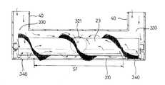
도시한 도 8a 는 본 발명에 따른 제2실시예를 나타낸 흡입구체의 개략적인 사시도이고, 도 8b 는 본 발명에 따른 제2실시예를 나타낸 흡입구체의 종단면도로서, 본 발명 제2실시예에서는 분사구(330)와 흡입유로(320) 사이인 흡입구체(300) 의 내부에 각각의 공간부를 구획하도록 구획판(350)을 구비하여서 된 것을 제시하고 있다.FIG. 8A is a schematic perspective view of a suction inlet port showing a second embodiment according to the present invention, and FIG. 8B is a longitudinal sectional view of the suction inlet port showing a second embodiment according to the present invention. The
이 때, 상기 구획판은 흡입구체(300)의 분사구(330) 및 흡입유로(320)를 완전히 구획하는 것이 아니라 상기 분사구를 통해 분사되는 공기가 흡입유로(320)로 유입될 수 있도록 일정 부분만을 차단하여 흡입구체(300) 내의 상부측을 통해 분사구(330)를 통해 분사된 분사공기의 일부는 흡입유로(320)가 위치된 측으로 직접 유동할 수 있도록 함이 바람직하다.At this time, the partition plate does not completely partition the
이는, 분사되는 공기가 집중된 상태로써 한 곳 즉, 분사구(330)의 공기 토출측이 형성된 위치로 분사되지 않도록 하기 위함이다.This is to prevent the injected air from being concentrated in one place, that is, the air discharge side of the
상기와 같은 구획판(350)의 구비로 인하여 나타나는 각 압력 즉, 흡입압력과 분사압력의 분할되는 현상은 도 9의 면압분포도를 통해 쉽게 알 수 있다.Each of the pressures, ie, the inhalation pressure and the injecting pressure, caused by the provision of the
도시한 도 10 은 본 발명에 따른 제3실시예를 나타낸 흡입구체의 단면도로서, 상기와 같은 본 발명의 제3실시예에서는 흡입구체(300)의 내부인 지면과 분사구(330)의 공기 유출측 사이에 압력강하부재(360)를 구비하여서 된 것을 제시하고 있다.FIG. 10 is a cross-sectional view of a suction port showing a third embodiment according to the present invention. In the third embodiment of the present invention, the air outlet side of the ground and the
이 때, 상기 압력강하부재는 분사구를 통해 분사되는 공기의 압력 강하를 위한 것으로써 이의 작용을 보다 원활히 행할 수 있도록 하기 위해서는 메쉬(mesh) 형상의 그물망으로 구성함이 바람직하다.At this time, the pressure drop member is for the pressure drop of the air injected through the injection port is preferably composed of a mesh (mesh) in order to be able to perform its operation more smoothly.
이는, 상기 그물망을 통과하여 공기가 통과할 수는 있으나 공기의 통과 과정중 분사되는 공기가 상기 그물망에 의해 분산되므로써 그 분사압력이 급격히 저하 될 수 있기 때문이다.This is because the air may pass through the mesh, but the spraying pressure may be drastically lowered as the air injected during the passage of air is dispersed by the mesh.
상기와 같은 본 발명의 각 실시예는 단순히 그 각각의 구성만 추가됨으로써 본 발명에 따른 작용이 보다 원활히 이루어질 수는 있으나 바람직하기로는 본 발명의 기본적인 구성에 상기 각각의 실시예를 동시에 적용하여 구현함이 본 발명에 따른 작용을 더욱 원활히 행할 수 있게 됨과 동시에 그에 따른 효과 역시 더욱 향상될 수 있게 된다.Each embodiment of the present invention as described above can be made more smoothly according to the present invention by simply adding the respective configuration, but preferably implemented by simultaneously applying the respective embodiments to the basic configuration of the present invention The operation according to the present invention can be performed more smoothly, and the effect thereof can be further improved.
이상에서 설명한 바와 같이 본 발명은 배기 환류식 진공 청소기의 구조를 개선함으로써 본체 내부를 환류한 공기가 흡입구체의 저면으로 분사된다 하더라도 그 분사력에 따른 압력이 흡입유로를 통해 발생되는 흡입압력에 대하여 미치는 영향을 최대한 방지함으로써 청소 성능을 저하시키지 않더라도 원활한 공기의 환류가 이루어질 수 있게 된 효과가 있다.As described above, the present invention improves the structure of the exhaust reflux vacuum cleaner so that even if the air refluxed inside the main body is injected to the bottom of the suction port, the pressure according to the injection force is applied to the suction pressure generated through the suction flow path. By preventing the effect as much as possible, it is possible to achieve a smooth reflux of the air even without degrading the cleaning performance.
또한, 배기공기에 의한 분사력에 의해 지면에 있는 각종 먼지등의 이물질이 비산됨을 최소화하여 각종 이물질의 비산됨에 따른 청소 성능 저하를 방지할 수 있게 된 효과 역시 있다.In addition, by minimizing the scattering of foreign matters such as dust on the ground by the injection force by the exhaust air there is also an effect that can prevent the deterioration of cleaning performance due to the scattering of various foreign matters.
결국, 이는 소비자의 신뢰성 저하를 방지할 수 있게되는 효과를 얻게 되는 유용한 발명이라 할 수 있다.After all, this can be said to be a useful invention that obtains the effect that can prevent the degradation of consumer reliability.
Claims (7)
Translated fromKoreanPriority Applications (1)
| Application Number | Priority Date | Filing Date | Title |
|---|---|---|---|
| KR1019990067395AKR100672398B1 (en) | 1999-12-30 | 1999-12-30 | Exhaust reflux vacuum cleaner |
Applications Claiming Priority (1)
| Application Number | Priority Date | Filing Date | Title |
|---|---|---|---|
| KR1019990067395AKR100672398B1 (en) | 1999-12-30 | 1999-12-30 | Exhaust reflux vacuum cleaner |
Publications (2)
| Publication Number | Publication Date |
|---|---|
| KR20010059858A KR20010059858A (en) | 2001-07-06 |
| KR100672398B1true KR100672398B1 (en) | 2007-01-23 |
Family
ID=19634504
Family Applications (1)
| Application Number | Title | Priority Date | Filing Date |
|---|---|---|---|
| KR1019990067395AExpired - Fee RelatedKR100672398B1 (en) | 1999-12-30 | 1999-12-30 | Exhaust reflux vacuum cleaner |
Country Status (1)
| Country | Link |
|---|---|
| KR (1) | KR100672398B1 (en) |
Citations (1)
| Publication number | Priority date | Publication date | Assignee | Title |
|---|---|---|---|---|
| JPH09187402A (en)* | 1996-01-09 | 1997-07-22 | K B Maintenance:Kk | Suction-operated dust collector |
- 1999
- 1999-12-30KRKR1019990067395Apatent/KR100672398B1/ennot_activeExpired - Fee Related
Patent Citations (1)
| Publication number | Priority date | Publication date | Assignee | Title |
|---|---|---|---|---|
| JPH09187402A (en)* | 1996-01-09 | 1997-07-22 | K B Maintenance:Kk | Suction-operated dust collector |
Also Published As
| Publication number | Publication date |
|---|---|
| KR20010059858A (en) | 2001-07-06 |
Similar Documents
| Publication | Publication Date | Title |
|---|---|---|
| KR101012375B1 (en) | Suction nozzle of vacuum cleaner | |
| JP2004160102A (en) | Vacuum cleaner | |
| US7788765B2 (en) | Air recirculating surface cleaning device | |
| CA2589219C (en) | Vacuum cleaner with spiral air guide | |
| KR100361876B1 (en) | Suction port body for vacuum-cleaner and vacuum-cleaner having the same | |
| US6725500B2 (en) | Air recirculating surface cleaning device | |
| CN111432704A (en) | Robot cleaner | |
| KR100672398B1 (en) | Exhaust reflux vacuum cleaner | |
| JP5323168B2 (en) | Floor brush and vacuum cleaner | |
| KR100628183B1 (en) | Vacuum cleaner | |
| US20050217065A1 (en) | Air recirculating surface cleaning device | |
| CN114762580B (en) | Collection box and base station thereof | |
| KR20010026686A (en) | suction nozzle in recirculating type vacuum cleaner | |
| KR20010059857A (en) | recirculating type vacuum cleaner | |
| KR20010055314A (en) | structure for recirculating air of flow passage in recirculating type vacuum cleaner | |
| KR100617225B1 (en) | Inlet for vacuum cleaner | |
| JPH07275164A (en) | Upright vacuum cleaner | |
| JP3815595B2 (en) | Vacuum cleaner and its suction port | |
| KR100628199B1 (en) | Exhaust reflux vacuum cleaner | |
| JP4912252B2 (en) | Floor brush and vacuum cleaner | |
| JP2002085303A (en) | Electric vacuum cleaner | |
| KR0137488B1 (en) | Dust scattering device of vacuum cleaner | |
| KR20070021763A (en) | Zero exhaust robot cleaner | |
| KR20010098260A (en) | device for changing mode in recirculating type vacuum cleaner | |
| JP3447208B2 (en) | Vacuum cleaner suction body |
Legal Events
| Date | Code | Title | Description |
|---|---|---|---|
| PA0109 | Patent application | St.27 status event code:A-0-1-A10-A12-nap-PA0109 | |
| PN2301 | Change of applicant | St.27 status event code:A-3-3-R10-R13-asn-PN2301 St.27 status event code:A-3-3-R10-R11-asn-PN2301 | |
| PN2301 | Change of applicant | St.27 status event code:A-3-3-R10-R13-asn-PN2301 St.27 status event code:A-3-3-R10-R11-asn-PN2301 | |
| PG1501 | Laying open of application | St.27 status event code:A-1-1-Q10-Q12-nap-PG1501 | |
| PN2301 | Change of applicant | St.27 status event code:A-3-3-R10-R13-asn-PN2301 St.27 status event code:A-3-3-R10-R11-asn-PN2301 | |
| N231 | Notification of change of applicant | ||
| PN2301 | Change of applicant | St.27 status event code:A-3-3-R10-R13-asn-PN2301 St.27 status event code:A-3-3-R10-R11-asn-PN2301 | |
| R18-X000 | Changes to party contact information recorded | St.27 status event code:A-3-3-R10-R18-oth-X000 | |
| A201 | Request for examination | ||
| PA0201 | Request for examination | St.27 status event code:A-1-2-D10-D11-exm-PA0201 | |
| E902 | Notification of reason for refusal | ||
| PE0902 | Notice of grounds for rejection | St.27 status event code:A-1-2-D10-D21-exm-PE0902 | |
| T11-X000 | Administrative time limit extension requested | St.27 status event code:U-3-3-T10-T11-oth-X000 | |
| T11-X000 | Administrative time limit extension requested | St.27 status event code:U-3-3-T10-T11-oth-X000 | |
| T11-X000 | Administrative time limit extension requested | St.27 status event code:U-3-3-T10-T11-oth-X000 | |
| T11-X000 | Administrative time limit extension requested | St.27 status event code:U-3-3-T10-T11-oth-X000 | |
| T11-X000 | Administrative time limit extension requested | St.27 status event code:U-3-3-T10-T11-oth-X000 | |
| P11-X000 | Amendment of application requested | St.27 status event code:A-2-2-P10-P11-nap-X000 | |
| P13-X000 | Application amended | St.27 status event code:A-2-2-P10-P13-nap-X000 | |
| E701 | Decision to grant or registration of patent right | ||
| PE0701 | Decision of registration | St.27 status event code:A-1-2-D10-D22-exm-PE0701 | |
| GRNT | Written decision to grant | ||
| PR0701 | Registration of establishment | St.27 status event code:A-2-4-F10-F11-exm-PR0701 | |
| PR1002 | Payment of registration fee | St.27 status event code:A-2-2-U10-U11-oth-PR1002 Fee payment year number:1 | |
| PG1601 | Publication of registration | St.27 status event code:A-4-4-Q10-Q13-nap-PG1601 | |
| PN2301 | Change of applicant | St.27 status event code:A-5-5-R10-R13-asn-PN2301 St.27 status event code:A-5-5-R10-R11-asn-PN2301 | |
| R18-X000 | Changes to party contact information recorded | St.27 status event code:A-5-5-R10-R18-oth-X000 | |
| R18-X000 | Changes to party contact information recorded | St.27 status event code:A-5-5-R10-R18-oth-X000 | |
| PR1001 | Payment of annual fee | St.27 status event code:A-4-4-U10-U11-oth-PR1001 Fee payment year number:4 | |
| PR1001 | Payment of annual fee | St.27 status event code:A-4-4-U10-U11-oth-PR1001 Fee payment year number:5 | |
| FPAY | Annual fee payment | Payment date:20111220 Year of fee payment:6 | |
| PR1001 | Payment of annual fee | St.27 status event code:A-4-4-U10-U11-oth-PR1001 Fee payment year number:6 | |
| FPAY | Annual fee payment | Payment date:20121227 Year of fee payment:7 | |
| PR1001 | Payment of annual fee | St.27 status event code:A-4-4-U10-U11-oth-PR1001 Fee payment year number:7 | |
| LAPS | Lapse due to unpaid annual fee | ||
| PC1903 | Unpaid annual fee | St.27 status event code:A-4-4-U10-U13-oth-PC1903 Not in force date:20140117 Payment event data comment text:Termination Category : DEFAULT_OF_REGISTRATION_FEE | |
| PC1903 | Unpaid annual fee | St.27 status event code:N-4-6-H10-H13-oth-PC1903 Ip right cessation event data comment text:Termination Category : DEFAULT_OF_REGISTRATION_FEE Not in force date:20140117 | |
| PN2301 | Change of applicant | St.27 status event code:A-5-5-R10-R13-asn-PN2301 St.27 status event code:A-5-5-R10-R11-asn-PN2301 | |
| P22-X000 | Classification modified | St.27 status event code:A-4-4-P10-P22-nap-X000 | |
| P22-X000 | Classification modified | St.27 status event code:A-4-4-P10-P22-nap-X000 | |
| PN2301 | Change of applicant | St.27 status event code:A-5-5-R10-R13-asn-PN2301 St.27 status event code:A-5-5-R10-R11-asn-PN2301 |