KR100671273B1 - Fabric signal line structure for smart clothing - Google Patents
Fabric signal line structure for smart clothingDownload PDFInfo
- Publication number
- KR100671273B1 KR100671273B1KR1020050054511AKR20050054511AKR100671273B1KR 100671273 B1KR100671273 B1KR 100671273B1KR 1020050054511 AKR1020050054511 AKR 1020050054511AKR 20050054511 AKR20050054511 AKR 20050054511AKR 100671273 B1KR100671273 B1KR 100671273B1
- Authority
- KR
- South Korea
- Prior art keywords
- signal line
- coupling means
- line
- fabric
- smart
- Prior art date
- Legal status (The legal status is an assumption and is not a legal conclusion. Google has not performed a legal analysis and makes no representation as to the accuracy of the status listed.)
- Expired - Fee Related
Links
Images


Classifications
- D—TEXTILES; PAPER
- D03—WEAVING
- D03D—WOVEN FABRICS; METHODS OF WEAVING; LOOMS
- D03D1/00—Woven fabrics designed to make specified articles
- D03D1/0088—Fabrics having an electronic function
- D—TEXTILES; PAPER
- D03—WEAVING
- D03D—WOVEN FABRICS; METHODS OF WEAVING; LOOMS
- D03D11/00—Double or multi-ply fabrics not otherwise provided for
- D—TEXTILES; PAPER
- D03—WEAVING
- D03D—WOVEN FABRICS; METHODS OF WEAVING; LOOMS
- D03D15/00—Woven fabrics characterised by the material, structure or properties of the fibres, filaments, yarns, threads or other warp or weft elements used
- D03D15/50—Woven fabrics characterised by the material, structure or properties of the fibres, filaments, yarns, threads or other warp or weft elements used characterised by the properties of the yarns or threads
- D03D15/527—Woven fabrics characterised by the material, structure or properties of the fibres, filaments, yarns, threads or other warp or weft elements used characterised by the properties of the yarns or threads waterproof or water-repellent
- D—TEXTILES; PAPER
- D03—WEAVING
- D03D—WOVEN FABRICS; METHODS OF WEAVING; LOOMS
- D03D15/00—Woven fabrics characterised by the material, structure or properties of the fibres, filaments, yarns, threads or other warp or weft elements used
- D03D15/50—Woven fabrics characterised by the material, structure or properties of the fibres, filaments, yarns, threads or other warp or weft elements used characterised by the properties of the yarns or threads
- D03D15/533—Woven fabrics characterised by the material, structure or properties of the fibres, filaments, yarns, threads or other warp or weft elements used characterised by the properties of the yarns or threads antistatic; electrically conductive
- D—TEXTILES; PAPER
- D03—WEAVING
- D03D—WOVEN FABRICS; METHODS OF WEAVING; LOOMS
- D03D15/00—Woven fabrics characterised by the material, structure or properties of the fibres, filaments, yarns, threads or other warp or weft elements used
- D03D15/50—Woven fabrics characterised by the material, structure or properties of the fibres, filaments, yarns, threads or other warp or weft elements used characterised by the properties of the yarns or threads
- D03D15/593—Stiff materials, e.g. cane or slat
- D—TEXTILES; PAPER
- D03—WEAVING
- D03D—WOVEN FABRICS; METHODS OF WEAVING; LOOMS
- D03D25/00—Woven fabrics not otherwise provided for
- G—PHYSICS
- G11—INFORMATION STORAGE
- G11B—INFORMATION STORAGE BASED ON RELATIVE MOVEMENT BETWEEN RECORD CARRIER AND TRANSDUCER
- G11B33/00—Constructional parts, details or accessories not provided for in the other groups of this subclass
- G11B33/12—Disposition of constructional parts in the apparatus, e.g. of power supply, of modules
- G11B33/125—Disposition of constructional parts in the apparatus, e.g. of power supply, of modules the apparatus comprising a plurality of recording/reproducing devices, e.g. modular arrangements, arrays of disc drives
- G11B33/126—Arrangements for providing electrical connections, e.g. connectors, cables, switches
- D—TEXTILES; PAPER
- D10—INDEXING SCHEME ASSOCIATED WITH SUBLASSES OF SECTION D, RELATING TO TEXTILES
- D10B—INDEXING SCHEME ASSOCIATED WITH SUBLASSES OF SECTION D, RELATING TO TEXTILES
- D10B2401/00—Physical properties
- D10B2401/02—Moisture-responsive characteristics
- D10B2401/021—Moisture-responsive characteristics hydrophobic
- D—TEXTILES; PAPER
- D10—INDEXING SCHEME ASSOCIATED WITH SUBLASSES OF SECTION D, RELATING TO TEXTILES
- D10B—INDEXING SCHEME ASSOCIATED WITH SUBLASSES OF SECTION D, RELATING TO TEXTILES
- D10B2401/00—Physical properties
- D10B2401/16—Physical properties antistatic; conductive
- D—TEXTILES; PAPER
- D10—INDEXING SCHEME ASSOCIATED WITH SUBLASSES OF SECTION D, RELATING TO TEXTILES
- D10B—INDEXING SCHEME ASSOCIATED WITH SUBLASSES OF SECTION D, RELATING TO TEXTILES
- D10B2401/00—Physical properties
- D10B2401/18—Physical properties including electronic components
- D—TEXTILES; PAPER
- D10—INDEXING SCHEME ASSOCIATED WITH SUBLASSES OF SECTION D, RELATING TO TEXTILES
- D10B—INDEXING SCHEME ASSOCIATED WITH SUBLASSES OF SECTION D, RELATING TO TEXTILES
- D10B2501/00—Wearing apparel
- D10B2501/06—Details of garments
Landscapes
- Engineering & Computer Science (AREA)
- Textile Engineering (AREA)
- Woven Fabrics (AREA)
Abstract
Translated fromKoreanDescription
Translated fromKorean도1은 본 발명에 따른 스마트 의류용 직물 신호선구조를 도시한 도면.1 is a view showing a signal line structure fabric for smart clothing according to the present invention.
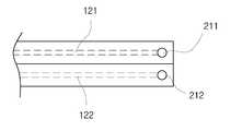
도2는 도1에 도시된 라인부(100)의 내부구성을 예시한 도면.2 is a diagram illustrating an internal configuration of the
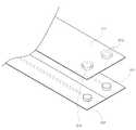
도3과 도4는 도1에 도시된 기기결합수단(200)과 전자기기에 구비된 신호선결합수단(410)의 구성을 예시한 도면.3 and 4 are views illustrating the configuration of the device coupling means 200 and the signal line coupling means 410 provided in the electronic device shown in FIG.
******* 도면의 주요부분에 대한 간단한 설명 ************** Brief description of the main parts of the drawing *******
100 : 라인부, 110 : 직물,100: line portion, 110: fabric,
120 : 신호라인, 121 : 신호전송용 라인,120: signal line, 121: signal transmission line,
122 : 접지용 라인, 200 : 기기결합수단.122: grounding line, 200: device coupling means.
본 발명은 스마트 의류에 전자기기 본체와 주변기기를 용이하게 결합시킬 수 있도록 해주는 스마트 의류용 직물 신호선구조에 관한 것이다.The present invention relates to a fabric signal line structure for smart clothing that makes it possible to easily combine the main body and peripheral devices with smart clothing.
음성서비스를 제공하는 통신기기는 일반적으로 본체와 음성출력 또는 음성입력을 위한 주변기기를 구비하게 된다. 상기 통신기기는 본체와 주변기기가 소정 거 리 떨어져 있는 상태에서도 상호 통신이 가능하도록 소정 케이블을 통해 결합된다. 이는 사용자가 주변기기는 자신의 얼굴부분에 위치시키고 본체는 수납이 편리한 곳에 위치시켜 통신기기를 편리하게 사용할 수 있도록 하기 위함이다.A communication device that provides a voice service generally includes a main body and a peripheral device for voice output or voice input. The communication device is coupled through a predetermined cable so that the main body and the peripheral device can communicate with each other even in a predetermined distance. This is to allow the user to conveniently use the communication device by placing the peripheral device on their face and the main body on a convenient storage area.
예컨대, MP3플레이어나 휴대용 카세트 등의 오디오기기는 그 음원출력을 위해 이어폰이나 헤드폰과 같은 주변기기가 결합된다. 또한, 음성통신서비스를 제공하는 이동통신단말기 등의 휴대단말기는 이어마이크가 결합된다. 특히, 최근에는 휴대단말기가 MP3 음원제공서비스를 제공하도록 구성됨으로써, 이어폰이나 헤드폰 또는 이어마이크 등과 같은 주변기기의 요구가 더욱 가중되고 있다.For example, an audio device such as an MP3 player or a portable cassette is combined with peripheral devices such as earphones or headphones for output of the sound source. In addition, a mobile terminal such as a mobile communication terminal providing a voice communication service is coupled to the ear microphone. In particular, recently, since a mobile terminal is configured to provide an MP3 sound source providing service, the demand for peripheral devices such as earphones, headphones, or ear microphones is increasing.
한편, 상기한 음성서비스를 제공하는 전자기기는 일반적으로 휴대용으로 구성된다. 즉, 사용자는 전자기기 본체는 의류의 포켓이나 가방에 수납하고 주변기기는 얼굴부분에 착용하게 된다. 이때, 전자기기 본체와 주변기기는 케이블을 통해 결합되고, 케이블은 사용자의 의류 외측에 노출된 상태로 있게 된다. 이는 케이블이 엉키거나 다른 물체에 걸리게 되는 등 사용자의 행동에 제약을 가하게 되는 요인으로 작용하게 됨은 물론, 의류의 패션성을 저하시키는 요인으로 작용하게 되는 문제가 있게 된다.On the other hand, electronic devices that provide the voice service are generally portable. That is, the user stores the main body of the electronic device in a pocket or a bag of clothing and wears the peripheral device on the face part. At this time, the main body of the electronic device and the peripheral device are coupled through a cable, and the cable remains in an exposed state outside the user's clothing. This will not only act as a factor that restricts the user's behavior, such as tangled cables or other objects, but also has a problem of decreasing the fashion of clothing.
특히, 최근 의류에 각종 전자기기가 내장된 형태로 구성되는 "웨어러블 컴퓨터"/"스마트 의류" 에 대한 개발이 진행되고 있으며, 이에 따라 착용 편의성과 사용 편의성, 인체의 자세와 동작 등 인체공학적 측면에 대한 배려를 고려한 전자기기 본체와 주변기기 간의 신호선 구조에 대한 개발이 요구된다.In particular, the development of "wearable computer" / "smart clothing" that is composed of a variety of electronic devices built into the clothing is in progress, according to the ergonomic aspects such as wearing comfort, ease of use, body posture and motion Development of signal line structure between electronic device main body and peripheral device is required.
대한민국실용신안등록 제 307433호에 의하면 이어폰리드선의 피복을 양쪽 날 개가 달린 형태로 변형구성하여 이를 이어폰줄과 피복선으로 사용하고 이어폰의 연결잭을 분리할 수 있도록 하여 이어폰줄을 의류와 일체형으로 박음직하여 사용할 수 있도록 구성된 신호선 구조가 제안되었다.According to the Republic of Korea Utility Model Registration No. 307433, the cover of the earphone lead wire is deformed and configured as the form with both wings, so that it can be used as the earphone line and the sheath line, and the connection jack of the earphone can be separated so that the earphone line is sewn together with the clothing. A signal line structure constructed for use has been proposed.
그러나, 상기 신호선 구조는 피복 내에 실제 신호선은 그대로 두고 그 외부의 피복선 구조만을 변경시켜 의류에 박음질을 통해 결합시킬 수 있도록 된 것으로 , 장기간 세탁시 신호선이 손상될 우려가 있게 된다.However, the signal line structure is such that the signal line structure can be coupled to the garment by stitching only the structure of the outer cover line without changing the actual signal line in the coating, so that the signal line may be damaged during long-term washing.
이에 본 발명은 상기한 사정을 감안하여 창출된 것으로, 전도성 섬유소재를 전자기기 본체와 주변기기간의 음성신호 전송을 위한 신호전송매체로 이용하여 신호선을 구성함으로써, 스마트 의류의 착용 편의성과 이용 편의성 및 의류의 세탁성을 고려하여 의류상에 본체와 주변기기를 용이하게 결합시킬 수 있도록 된 스마트 의류용 직물 신호선구조를 제공함에 그 기술적 목적이 있다.Accordingly, the present invention has been made in view of the above circumstances, and by using a conductive fiber material as a signal transmission medium for transmitting a voice signal between an electronic device body and a peripheral device, by constructing a signal line, the convenience and convenience of wearing smart clothes and clothing It is a technical object of the present invention to provide a fabric signal line structure for smart clothing that can be easily coupled to the main body and peripherals on the clothes in consideration of the washability of the.
상기 목적을 달성하기 위한 본 발명에 따른 스마트 의류용 직물 신호선구조는 직물 내측에 전도성 섬유소재로 구성되는 신호전송용 제1 라인과 접지용 제2 라인이 이격 배치되는 라인부와, 상기 제1 및 제2 라인과 결합되면서 소정 전자기기와 전기적으로 결합하기 위한 기기결합수단이 구비되어 구성되는 것을 특징으로 한다.Fabric signal line structure for smart clothing according to the present invention for achieving the above object is a line portion in which the first line for signal transmission and the second line for grounding is made of a conductive fiber material disposed inside the fabric, and the first and It is characterized in that the device is coupled to the second line is provided with a device coupling means for electrically coupling with a predetermined electronic device.
또한, 상기 직물은 방수재질로 구성되는 것을 특징으로 한다.In addition, the fabric is characterized in that consisting of a waterproof material.
또한, 상기 기기결합수단은 전자기기에 구비된 신호선결합수단과 착탈가능하 도록 구성되는 것을 특징으로 한다.In addition, the device coupling means is characterized in that it is configured to be detachable with the signal line coupling means provided in the electronic device.
또한, 상기 기기결합수단은 전도성을 갖는 제1 형상으로 된 스냅단추로 구성되고, 상기 신호선결합수단은 전도성을 가지면서 제1 형상에 대응되는 제2 형상으로 된 스냅단추로 구성되는 것을 특징으로 한다.In addition, the device coupling means is composed of a snap button having a first shape having a conductivity, the signal line coupling means is characterized by consisting of a snap button having a second shape corresponding to the first shape while having conductivity. .
또한, 상기 기기결합수단은 전도성을 갖는 재질의 스냅단추형상으로 구성되고, 상기 신호선결합수단은 스냅단추사이에 끼움결합되는 전도성을 갖는 재질의 링타입 터미널형상으로 구성되는 것을 특징으로 한다.In addition, the device coupling means is composed of a snap button shape of a conductive material, the signal line coupling means is characterized in that it is composed of a ring-type terminal shape of a conductive material that is fitted between the snap button.
즉, 상기한 바에 의하면 전도성 섬유소재를 본체와 주변기기간의 음성신호 전송을 위한 신호전송매체로 이용하여 신호선을 구성함으로써, 스마트 의류의 착용 편의성과 이용 편의성 및 의류의 세탁성을 고려하여 스마트 의류상에 본체와 주변기기를 용이하게 결합시킬 수 있게 된다.That is, according to the above, by using a conductive fiber material as a signal transmission medium for transmitting a voice signal between the main body and the peripheral device, a signal line is formed, taking into account the convenience and convenience of use of the smart clothes, and the washability of the clothes. The main body and peripherals can be easily coupled.
먼저, 본 발명은 전도성 섬유소재를 이용하여 신호선을 구성한 것이다. 예컨대, 전도성 섬유소재로서 전자파 차폐기능이 부여된 직물지는 직물표면에 니켈, 구리, 니켈이 순처적으로 배치된 전자파 차폐소재를 무전해 도금처리하여 구성된다.First, the present invention is to configure a signal line using a conductive fiber material. For example, a textile paper provided with an electromagnetic shielding function as a conductive fiber material is constituted by electroless plating of an electromagnetic shielding material in which nickel, copper, and nickel are sequentially disposed on the fabric surface.
한편, 전기 신호는 고주파와 저주파신호로 분류된다. 그리고, 일반적으로 고주파신호는 유전체내에서 전기자기장 형태로 신호전송이 행해지고, 저주파신호는 구리 등의 금속 도선을 통해 신호전송이 행해지게 된다.On the other hand, electrical signals are classified into high frequency and low frequency signals. In general, a high frequency signal is transmitted in the form of an electric magnetic field in a dielectric, and a low frequency signal is transmitted through a metal conductor such as copper.
본 발명에서는 상기한 사항을 근거로 전도성 섬유소재를 저주파로 분류되는 음성신호의 신호전송매체로 이용한 것이다.In the present invention, the conductive fiber material is used as a signal transmission medium for speech signals classified into low frequencies based on the above matters.
이하 본 발명에 따른 실시예를 도면을 참조하여 설명한다.Hereinafter, embodiments according to the present invention will be described with reference to the drawings.
도1은 본 발명에 따른 스마트 의류용 직물 신호선 구조를 도시한 것이다. 도시된 바와 같이 본 발명에 따른 스마트 의류용 직물 신호선 구조는 직물(110)의 내측에 전자파차폐소재의 신호라인(120)이 배치구성되는 라인부(100)와, 이 신호라인(120)의 끝단에 배치되어 전자기기의 본체(300) 및 주변기기(400)와 전기적으로 결합시키는 기기결합수단(200: 210,220)으로 구성된다.1 illustrates a fabric signal line structure for a smart garment according to the present invention. As shown, the fabric signal line structure for smart clothing according to the present invention is the
여기서, 상기 본체(300)는 음성통신서비스를 제공하기 위한 각종 휴대통신단말기나 음원출력서비스를 제공하는 MP3플레이어 등의 각종 미디어기기가 될 수 있다. 그리고, 상기 주변기기(400)는 음성출력기능을 갖는 헤드폰이나 이어폰, 또는 음성입출력기능을 갖는 이어마이크폰 등이 될 수 있다.Here, the main body 300 may be various media devices such as various portable communication terminals for providing a voice communication service or an MP3 player for providing a sound source output service. The peripheral device 400 may be a headphone or earphone having a voice output function, or an ear microphone having a voice input / output function.
또한, 상기 직물(110)은 그 내부에 배치된 신호라인(120)으로 수분이 침투하는 것을 방지하기 위해 방수기능을 갖는 재질로 구성된다. 그리고, 상기 2장의 직물(110)은 통상 바느질에 의해 봉재결합되게 되는데, 이때 바늘구멍에 의해 신호라인(120)으로 수분이 침투하는 것을 방지하기 위해 심실링(seam sealing)처리를 수행하는 것이 바람직할 것이다.In addition, the
또한, 상기 신호라인(120)은 신호전송을 위한 전기적인 특성을 만족하는 면저항값을 갖도록 그 넓이가 설정된다. 예컨대, 본 발명자가 실험한 바에 의하면 이어폰선의 신호선 길이가 60cm인 경우 그 임피던스값이 0.7Ω로 측정되었는 바, 이를 근거로 본 발명에서도 신호선 길이가 60cm로 설정된 경우 그 면저항값이 0.7Ω이 되도록 신호라인(120)의 넓이를 설정하게 된다. 이때, 신호라인(120)의 금속성분 함량을 조절하여 면저항값을 설정하도록 실시하는 것도 가능할 것이다.In addition, the width of the
도2는 도1에 도시된 라인부(100)의 구성을 예시한 도면이다.FIG. 2 is a diagram illustrating a configuration of the
즉, 상기 라인부(100)는 도2a에 도시된 바와 같이 상기 신호전송용 라인(121)과 접지용 라인(122)이 소정 거리 이격된 형태로 상호 평행하도록 2장의 직물(110) 사이에 배치되어 구성된다.That is, the
또한, 상기 라인부(100)는 도2b에 도시된 바와 같이 2장의 직물(110) 사이에 2장의 접지용 라인(122)이 배치되고, 이 2장의 접지용 라인(122) 사이에 접지용 라인(122)보다 작은 넓이의 2장의 차단재(111)가 배치되며, 이 2장의 차단재(111) 사이에 차단재(111) 보다 작은 넓이의 신호전송용 라인(121)이 배치되어 구성하는 것도 가능하다.In addition, the
한편, 상기 기기결합수단(210,220)은 본체(300) 또는 주변기기(400)와 고정 결합되거나 또는 착탈가능하도록 구성될 수 있다. 여기서, 기기결합수단(210,220)이 본체(300) 또는 주변기기(400)와 착탈가능한 형태로 구성되는 경우, 본체(300) 또는 주변기기(400)는 상기 기기결합수단(210,220)과 착탈가능하도록 된 형태의 신호선결합수단(410)이 구비된다.Meanwhile, the device coupling means 210 and 220 may be configured to be fixedly coupled to or detachable from the main body 300 or the peripheral device 400. Here, when the device coupling means (210, 220) is configured to be detachable from the main body 300 or the peripheral device 400, the main body 300 or the peripheral device 400 is detachable form with the device coupling means (210, 220) The signal line coupling means 410 is provided.
도3과 도4는 기기결합수단(210)과 신호선결합수단(410)의 구성을 예시한 것으로, 본체(300)의 신호선결합수단(410)과 기기결합수단(220)의 구성도 이와 동일하다. 이때, 상기 기기결합수단(210)과 신호선결합수단(410)은 상호 임피던스 매칭이 되도록 그 접촉면적이 설정된다. 또한, 상기 기기결합수단(210) 또는 신호선결합수단(410)에 금이나 은 코팅처리를 수행하도록 실시하는 것도 가능하다.3 and 4 illustrate the configuration of the device coupling means 210 and the signal line coupling means 410, the configuration of the signal line coupling means 410 and the device coupling means 220 of the main body 300 is the same. . At this time, the device coupling means 210 and the signal line coupling means 410 is set to the contact area so that mutual impedance matching. In addition, the device coupling means 210 or the signal line coupling means 410 may be performed to perform a gold or silver coating treatment.
즉, 기기결합수단(210)은 도3a에 도시된 바와 같이 라인부(100)의 신호전송 용 라인(121)과 결합되는 전도성을 갖는 재질의 제1 결합수단(211)과 라인부(100)의 접지용 라인(122)과 결합되는 전도성을 갖는 재질의 제2 결합수단(212)로 구성된다. 이때, 제1 결합수단(211)은 주변기기(300)의 신호선과 연결된 신호선결합수단(410)과 체결되고, 제2 결합수단(212)은 주변기기(300)의 접지선과 연결된 신호선결합수단(410)과 결합되게 된다. 다시말해, 상기 주변기기(300)의 신호선결합수단(410)은 상기 제1 및 제2 결합수단(211,212)과 착탈가능하도록 된 형상으로 구성된다. 도3b는 제1 및 제2 결합수단(211,212)는 철(凸)형상으로 구성되고 신호선결합수단(410)는 요(凹)형상으로 구성되어 스냅단추형태로 결합되는 형태를 예시한 것이다.That is, the device coupling means 210 is the first coupling means 211 and the
또한, 상기 기기결합수단(210)은 도4a에 도시된 바와 같이 라인부(100)는 신호전송용 차폐소재(121)와 결합되는 전도성을 갖는 재질의 제1 결합수단(211)과 라인부(100)의 접지용 차폐소재(122)와 결합되는 전도성을 갖는 제2 결합수단(212)로 구성된다. 그리고, 제1 및 제2 결합수단(211,212)의 상측에는 일단이 라인부(100)의 직물(110)과 봉재처리되는 직물 재질의 덮개(230)가 형성되고, 이 덮개(230)의 하측에는 상기 제1 및 제2 결합수단(211,212)와 체결가능하도록 된 형상의 제3 및 제4 결합수단(213,214)가 결합되어 구성된다. 이때, 상기 제1 및 제2 결합수단(211,212)과 제3 및 제4 결합수단(213,214)은 스냅단추형태로 결합되도록 구성할 수 있다. 또한, 신호선결합부(410)은 도4b에 도시된 바와 같이 전도성을 갖는 금속재질로 구성되면서 그 내측에 소정 관통공(411)을 형성하도록 된 링타입 터미널형태로 구성할 수 있다. 즉, 도4c에 도시된 바와 같이 철(凸)형상의 제1 및 제2 결합수단(211,212)의 상측에 링타입 터미널 형상의 신호선결합부(410)를 끼우고, 이 상태에서 요(凹)형상의 제3 및 제4 결합수단(213,214)를 제1 및 제2 결합수단(211,212)와 체결하도록 구성함으로써, 신호선과 주변기기(300)를 전기적으로 결합시키게 된다.In addition, the device coupling means 210, the
한편, 상기 구성으로 된 직물 신호선은 의류에 박음질 형태로 봉재결합되거나 또는 의류 제조시 일체로 구성하는 것이 가능하다. 이때, 전자기기를 결합하기 위한 결합수단은 의류의 패션성을 고려하여 내측 시접부분이나 의류의 부자재 위치에 배치시키는 것이 바람직할 것이다.On the other hand, the fabric signal line having the above configuration can be sewn or sewn into the garment in the form of sewn or integrally configured when manufacturing the garment. In this case, the coupling means for coupling the electronic device may be disposed at the inner seam allowance portion or the subsidiary material position of the garment in consideration of the fashion of the garment.
즉, 상기 실시예에 의하면 전도성 섬유소재를 본체와 주변기기간의 음성신호 전송을 위한 신호전송매체로 구성함으로써, 스마트 의류의 착용 편의성과 이용 편의성 및 의류의 세탁성을 고려하여 스마트 의류상에 본체와 주변기기를 용이하게 결합시킬 수 있게 된다.That is, according to the above embodiment, the conductive fiber material is configured as a signal transmission medium for transmitting a voice signal between the main body and the peripheral device, so that the main body and the peripheral device on the smart clothes in consideration of the convenience and convenience of use of the smart clothes and the washability of the clothes. It can be easily combined.
한편, 본 발명은 상기 실시예에 한정되지 않고 본 발명의 기술적 사상을 벗어나지 않는 범위내에서 다양하게 변형 실시하는 것이 가능하다.In addition, the present invention is not limited to the above embodiments, and various modifications can be made without departing from the technical spirit of the present invention.
이상 설명한 바와 같이 본 발명에 의하면 전도성 섬유소재를 본체와 주변기기간의 음성신호 전송을 위한 신호전송매체로 이용하여 신호선을 구성함으로써, 스마트 의류의 착용 편의성과 이용 편의성 및 의류의 세탁성을 고려하여 스마트 의류상에 본체와 주변기기를 용이하게 결합시킬 수 있게 된다.As described above, according to the present invention, by using a conductive fiber material as a signal transmission medium for transmitting a voice signal between a main body and a peripheral device, a signal line is formed, so that smart clothes can be considered in consideration of wearing convenience, convenience of use, and washing of clothes. It is possible to easily combine the main body and the peripheral device on the.
Claims (5)
Translated fromKoreanPriority Applications (1)
| Application Number | Priority Date | Filing Date | Title |
|---|---|---|---|
| KR1020050054511AKR100671273B1 (en) | 2005-06-23 | 2005-06-23 | Fabric signal line structure for smart clothing |
Applications Claiming Priority (1)
| Application Number | Priority Date | Filing Date | Title |
|---|---|---|---|
| KR1020050054511AKR100671273B1 (en) | 2005-06-23 | 2005-06-23 | Fabric signal line structure for smart clothing |
Publications (2)
| Publication Number | Publication Date |
|---|---|
| KR20060134645A KR20060134645A (en) | 2006-12-28 |
| KR100671273B1true KR100671273B1 (en) | 2007-01-19 |
Family
ID=37812985
Family Applications (1)
| Application Number | Title | Priority Date | Filing Date |
|---|---|---|---|
| KR1020050054511AExpired - Fee RelatedKR100671273B1 (en) | 2005-06-23 | 2005-06-23 | Fabric signal line structure for smart clothing |
Country Status (1)
| Country | Link |
|---|---|
| KR (1) | KR100671273B1 (en) |
Families Citing this family (4)
| Publication number | Priority date | Publication date | Assignee | Title |
|---|---|---|---|---|
| KR100889985B1 (en)* | 2007-06-26 | 2009-03-25 | 연세대학교 산학협력단 | Textile substrates and manufacturing method thereof |
| KR102286576B1 (en)* | 2014-09-01 | 2021-08-06 | 한국전자통신연구원 | Smart wear system and method for correcting a posture of golf-swing using the system |
| KR102099634B1 (en)* | 2018-12-28 | 2020-04-10 | 한국패션산업연구원 | Electronic textile module having touch function |
| KR102813146B1 (en)* | 2023-01-25 | 2025-05-28 | 서울대학교산학협력단 | Seam tape and method for connecting the seam tape to electronic devices |
Citations (4)
| Publication number | Priority date | Publication date | Assignee | Title |
|---|---|---|---|---|
| US4813459A (en) | 1984-09-25 | 1989-03-21 | Semtronics Corporation | Stretchable material having redundant conductive sections |
| KR20020029097A (en)* | 2000-06-12 | 2002-04-17 | 요트.게.아. 롤페즈 | Garment with removable electronic devices |
| KR20020029095A (en)* | 2000-06-12 | 2002-04-17 | 요트.게.아. 롤페즈 | Garment carrying electronic devices |
| KR20050016620A (en)* | 2002-06-28 | 2005-02-21 | 코닌클리케 필립스 일렉트로닉스 엔.브이. | A mechanism for electrically connecting an electronic device to a garment |
- 2005
- 2005-06-23KRKR1020050054511Apatent/KR100671273B1/ennot_activeExpired - Fee Related
Patent Citations (4)
| Publication number | Priority date | Publication date | Assignee | Title |
|---|---|---|---|---|
| US4813459A (en) | 1984-09-25 | 1989-03-21 | Semtronics Corporation | Stretchable material having redundant conductive sections |
| KR20020029097A (en)* | 2000-06-12 | 2002-04-17 | 요트.게.아. 롤페즈 | Garment with removable electronic devices |
| KR20020029095A (en)* | 2000-06-12 | 2002-04-17 | 요트.게.아. 롤페즈 | Garment carrying electronic devices |
| KR20050016620A (en)* | 2002-06-28 | 2005-02-21 | 코닌클리케 필립스 일렉트로닉스 엔.브이. | A mechanism for electrically connecting an electronic device to a garment |
Also Published As
| Publication number | Publication date |
|---|---|
| KR20060134645A (en) | 2006-12-28 |
Similar Documents
| Publication | Publication Date | Title |
|---|---|---|
| JP3209546U (en) | Antenna for wireless earphone | |
| US10297911B2 (en) | Antenna for use in a wearable device | |
| CN206314707U (en) | Earplug | |
| CA2662472C (en) | Wireless microphone device with high frequency signals | |
| CN111902079A (en) | Fabric-based article with stretchable belt | |
| JP2007515563A (en) | Clothes having inductive buttons and button holes | |
| KR20060032593A (en) | Headset wire | |
| KR19990062838A (en) | Holder for portable electronic device | |
| CN105872887B (en) | Wireless earphone | |
| US20210376881A1 (en) | Wearable Device With Conductive Coil for Wireless Charging and Communicating | |
| KR20170136293A (en) | Portable sound equipment | |
| CN103682724B (en) | Mobile terminal | |
| US20230387575A1 (en) | Antenna designs for hearing instruments | |
| KR100671273B1 (en) | Fabric signal line structure for smart clothing | |
| KR101176419B1 (en) | Electronic module interconnection system for digital garment | |
| US8150088B2 (en) | Condenser microphone | |
| CN209517444U (en) | Headset assembly, earphone and earphone base | |
| KR101377583B1 (en) | Conductive structure for clothes which transmit electric or signal | |
| JP4353852B2 (en) | Condenser microphone | |
| WO2017135848A1 (en) | Heart activity monitor integrated with wired headphones | |
| CN215956606U (en) | Headphones and Headphone Components | |
| KR20180039392A (en) | Smart clothes having connector | |
| CN210489810U (en) | Near-field magnetic induction antenna device for electronic equipment and electronic equipment | |
| KR20100097921A (en) | Bluetooth and walkie-talkie communication jacket | |
| US20120314895A1 (en) | Sheath to mask electrical conductor |
Legal Events
| Date | Code | Title | Description |
|---|---|---|---|
| A201 | Request for examination | ||
| PA0109 | Patent application | St.27 status event code:A-0-1-A10-A12-nap-PA0109 | |
| PA0201 | Request for examination | St.27 status event code:A-1-2-D10-D11-exm-PA0201 | |
| D13-X000 | Search requested | St.27 status event code:A-1-2-D10-D13-srh-X000 | |
| D14-X000 | Search report completed | St.27 status event code:A-1-2-D10-D14-srh-X000 | |
| E902 | Notification of reason for refusal | ||
| PE0902 | Notice of grounds for rejection | St.27 status event code:A-1-2-D10-D21-exm-PE0902 | |
| P11-X000 | Amendment of application requested | St.27 status event code:A-2-2-P10-P11-nap-X000 | |
| P13-X000 | Application amended | St.27 status event code:A-2-2-P10-P13-nap-X000 | |
| E701 | Decision to grant or registration of patent right | ||
| PE0701 | Decision of registration | St.27 status event code:A-1-2-D10-D22-exm-PE0701 | |
| PG1501 | Laying open of application | St.27 status event code:A-1-1-Q10-Q12-nap-PG1501 | |
| GRNT | Written decision to grant | ||
| PR0701 | Registration of establishment | St.27 status event code:A-2-4-F10-F11-exm-PR0701 | |
| PR1002 | Payment of registration fee | St.27 status event code:A-2-2-U10-U11-oth-PR1002 Fee payment year number:1 | |
| PG1601 | Publication of registration | St.27 status event code:A-4-4-Q10-Q13-nap-PG1601 | |
| PR1001 | Payment of annual fee | St.27 status event code:A-4-4-U10-U11-oth-PR1001 Fee payment year number:4 | |
| PR1001 | Payment of annual fee | St.27 status event code:A-4-4-U10-U11-oth-PR1001 Fee payment year number:5 | |
| PN2301 | Change of applicant | St.27 status event code:A-5-5-R10-R13-asn-PN2301 St.27 status event code:A-5-5-R10-R11-asn-PN2301 | |
| PR1001 | Payment of annual fee | St.27 status event code:A-4-4-U10-U11-oth-PR1001 Fee payment year number:6 | |
| R17-X000 | Change to representative recorded | St.27 status event code:A-5-5-R10-R17-oth-X000 | |
| FPAY | Annual fee payment | Payment date:20130115 Year of fee payment:7 | |
| PR1001 | Payment of annual fee | St.27 status event code:A-4-4-U10-U11-oth-PR1001 Fee payment year number:7 | |
| R18-X000 | Changes to party contact information recorded | St.27 status event code:A-5-5-R10-R18-oth-X000 | |
| PN2301 | Change of applicant | St.27 status event code:A-5-5-R10-R13-asn-PN2301 St.27 status event code:A-5-5-R10-R11-asn-PN2301 | |
| FPAY | Annual fee payment | Payment date:20140102 Year of fee payment:8 | |
| PR1001 | Payment of annual fee | St.27 status event code:A-4-4-U10-U11-oth-PR1001 Fee payment year number:8 | |
| R18-X000 | Changes to party contact information recorded | St.27 status event code:A-5-5-R10-R18-oth-X000 | |
| FPAY | Annual fee payment | Payment date:20150227 Year of fee payment:9 | |
| PR1001 | Payment of annual fee | St.27 status event code:A-4-4-U10-U11-oth-PR1001 Fee payment year number:9 | |
| FPAY | Annual fee payment | Payment date:20160111 Year of fee payment:10 | |
| PR1001 | Payment of annual fee | St.27 status event code:A-4-4-U10-U11-oth-PR1001 Fee payment year number:10 | |
| P22-X000 | Classification modified | St.27 status event code:A-4-4-P10-P22-nap-X000 | |
| FPAY | Annual fee payment | Payment date:20170111 Year of fee payment:11 | |
| PR1001 | Payment of annual fee | St.27 status event code:A-4-4-U10-U11-oth-PR1001 Fee payment year number:11 | |
| FPAY | Annual fee payment | Payment date:20180205 Year of fee payment:12 | |
| PR1001 | Payment of annual fee | St.27 status event code:A-4-4-U10-U11-oth-PR1001 Fee payment year number:12 | |
| FPAY | Annual fee payment | Payment date:20190107 Year of fee payment:13 | |
| PR1001 | Payment of annual fee | St.27 status event code:A-4-4-U10-U11-oth-PR1001 Fee payment year number:13 | |
| PR1001 | Payment of annual fee | St.27 status event code:A-4-4-U10-U11-oth-PR1001 Fee payment year number:14 | |
| PC1903 | Unpaid annual fee | St.27 status event code:A-4-4-U10-U13-oth-PC1903 Not in force date:20210113 Payment event data comment text:Termination Category : DEFAULT_OF_REGISTRATION_FEE | |
| PC1903 | Unpaid annual fee | St.27 status event code:N-4-6-H10-H13-oth-PC1903 Ip right cessation event data comment text:Termination Category : DEFAULT_OF_REGISTRATION_FEE Not in force date:20210113 | |
| P22-X000 | Classification modified | St.27 status event code:A-4-4-P10-P22-nap-X000 | |
| R18-X000 | Changes to party contact information recorded | St.27 status event code:A-5-5-R10-R18-oth-X000 | |
| PN2301 | Change of applicant | St.27 status event code:A-5-5-R10-R13-asn-PN2301 St.27 status event code:A-5-5-R10-R11-asn-PN2301 |