KR100669677B1 - Solid Electrolyte and Manufacturing Method Thereof - Google Patents
Solid Electrolyte and Manufacturing Method ThereofDownload PDFInfo
- Publication number
- KR100669677B1 KR100669677B1KR1020000032100AKR20000032100AKR100669677B1KR 100669677 B1KR100669677 B1KR 100669677B1KR 1020000032100 AKR1020000032100 AKR 1020000032100AKR 20000032100 AKR20000032100 AKR 20000032100AKR 100669677 B1KR100669677 B1KR 100669677B1
- Authority
- KR
- South Korea
- Prior art keywords
- solid electrolyte
- electrolyte
- lithium
- ion
- nitrogen
- Prior art date
- Legal status (The legal status is an assumption and is not a legal conclusion. Google has not performed a legal analysis and makes no representation as to the accuracy of the status listed.)
- Expired - Fee Related
Links
Images
Classifications
- H—ELECTRICITY
- H01—ELECTRIC ELEMENTS
- H01M—PROCESSES OR MEANS, e.g. BATTERIES, FOR THE DIRECT CONVERSION OF CHEMICAL ENERGY INTO ELECTRICAL ENERGY
- H01M10/00—Secondary cells; Manufacture thereof
- H01M10/05—Accumulators with non-aqueous electrolyte
- H01M10/056—Accumulators with non-aqueous electrolyte characterised by the materials used as electrolytes, e.g. mixed inorganic/organic electrolytes
- H01M10/0561—Accumulators with non-aqueous electrolyte characterised by the materials used as electrolytes, e.g. mixed inorganic/organic electrolytes the electrolyte being constituted of inorganic materials only
- H01M10/0562—Solid materials
- Y—GENERAL TAGGING OF NEW TECHNOLOGICAL DEVELOPMENTS; GENERAL TAGGING OF CROSS-SECTIONAL TECHNOLOGIES SPANNING OVER SEVERAL SECTIONS OF THE IPC; TECHNICAL SUBJECTS COVERED BY FORMER USPC CROSS-REFERENCE ART COLLECTIONS [XRACs] AND DIGESTS
- Y02—TECHNOLOGIES OR APPLICATIONS FOR MITIGATION OR ADAPTATION AGAINST CLIMATE CHANGE
- Y02E—REDUCTION OF GREENHOUSE GAS [GHG] EMISSIONS, RELATED TO ENERGY GENERATION, TRANSMISSION OR DISTRIBUTION
- Y02E60/00—Enabling technologies; Technologies with a potential or indirect contribution to GHG emissions mitigation
- Y02E60/10—Energy storage using batteries
Landscapes
- Chemical & Material Sciences (AREA)
- Physics & Mathematics (AREA)
- Condensed Matter Physics & Semiconductors (AREA)
- General Physics & Mathematics (AREA)
- Inorganic Chemistry (AREA)
- Engineering & Computer Science (AREA)
- Manufacturing & Machinery (AREA)
- Chemical Kinetics & Catalysis (AREA)
- Electrochemistry (AREA)
- General Chemical & Material Sciences (AREA)
- Conductive Materials (AREA)
Abstract
Translated fromKoreanDescription
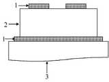
Translated fromKorean도 1은 본 발명의 실시예들 및 비교예에 따라 제조된 고체 전해질(2)의 특성을 평가하기 위한 장치의 구조를 개략적으로 나타낸 도면이다.1 is a view schematically showing the structure of an apparatus for evaluating the properties of a
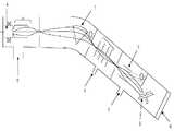
도 2는 본 발명의 실시예들 및 비교예에 따라 제조된 고체 전해질(2)의 특성을 향상시키기 위한 이온 주입기의 구조를 개략적으로 나타낸 도면이다.2 is a view schematically showing the structure of an ion implanter for improving the properties of the
<도면의 주요 부분에 대한 간단한 설명><Brief description of the main parts of the drawing>
1... 차단전극(blocking electrode) 2... 고체 전해질1
3... 유리기판4... 가스 소스3
5... 기판6... 펌프5 ...
7... 질량분석(Mass analysis)영역7 ... Mass analysis area
8... 웨이어 로딩 영역(Wafer loading zone)8 ... Wafer loading zone
9... 정전반사판(Electrostatic Deflection Plates)9 ... Electrostatic Deflection Plates
본 발명은 고체 전해질 및 이의 제조방법에 관한 것으로서, 보다 상세하기로 는 이온 주입(ion implantation)을 이용하여 화학적 안정성이 우수한 2차전지의 고체 전해질의 이온 전도도 특성을 개선시킬 수 있는 전해질의 제조방법과 이 방법에 따라 제조된 고체 전해질에 관한 것이다.The present invention relates to a solid electrolyte and a method for preparing the same, and more particularly, to a method for preparing an electrolyte capable of improving ion conductivity characteristics of a solid electrolyte having excellent chemical stability by using ion implantation. And to a solid electrolyte prepared according to this method.
최근 들어 반도체 산업이 발달되고 집적도가 향상됨으로써 전자기기들이 점차 소형화 및 경량화되고 있다. 따라서, 이에 요구되는 전류와 전력의 수준이 크게 낮아지는 추세이다. 이러한 추세에 발맞추어 고상전지의 실용화가 가능해졌고, 이를 위해서 리튬 2차 전지에 대한 연구가 매우 활발하게 이루어지고 있다. 리튬 2차 전지는 리튬의 낮은 전극 전위로 인하여 높은 에너지 밀도를 얻을 수 있고, 이온 전도도 특성이 우수한 리튬 이온 전도체의 존재로 고체 전해질로 사용 가능하다는 잇점을 갖고 있다.Recently, as the semiconductor industry is developed and the degree of integration is increased, electronic devices are becoming smaller and lighter. Therefore, the level of current and power required for this tends to be greatly lowered. In line with this trend, the practical use of solid-state batteries has become possible, and for this, research on lithium secondary batteries has been actively conducted. Lithium secondary batteries have the advantage of being able to obtain a high energy density due to the low electrode potential of lithium and to be used as a solid electrolyte due to the presence of lithium ion conductors having excellent ion conductivity characteristics.
한편, 박막전지는 전지 구성 성분들이 박막 형태 예를 들어, 두께 1㎛ 정도로 제조되므로 여러가지 잇점을 갖고 있다. 즉, 박막을 증착하여 캐소드 근처에 애노드를 배치하므로 전류밀도가 높고, 전지 효율 특성이 우수하고 반응물질의 함량을 매우 줄일 수 있게 된다. 이와 같이 반응물질의 함량을 줄일 수 있게 되는 것은 박막층에서는 이온간의 이동거리가 줄어들게 되어 이온의 이동이 보다 용이해지고 빨라지기 때문이다.On the other hand, the thin film battery has various advantages because the battery components are manufactured in the form of a thin film, for example, about 1 μm thick. That is, since the anode is disposed near the cathode by depositing a thin film, the current density is high, the battery efficiency characteristics are excellent, and the content of the reactant can be greatly reduced. As such, the content of the reactant can be reduced because the moving distance between the ions decreases in the thin film layer, thereby making the movement of the ions easier and faster.
박막 전지는 기본적으로 캐소드, 전해질 및 애노드가 박막 형태로 순차적으로 적층된 구조를 갖고 있다. 이러한 박막 전지의 성능은 전해질의 특성에 따라 매우 달라진다. 리튬 2차전지에 사용하기 위해서는 전해질은 리튬 이온 이동도가 높고 리튬 이온과 접촉하여 화학적으로 안정해야 한다.A thin film battery basically has a structure in which a cathode, an electrolyte, and an anode are sequentially stacked in a thin film form. The performance of such thin film cells is very dependent on the characteristics of the electrolyte. For use in lithium secondary batteries, the electrolyte must have high lithium ion mobility and be chemically stable in contact with lithium ions.
이 때 상기 전해질로는 고체 전해질을 사용하며, 따라서 액체 전해질을 사용하는 경우에 발생되는 문제점 즉, 저온 결빙, 고온 증발 등의 문제점이 미연에 방지되며, 액체 전해질의 누액에 따른 기기의 오염 등의 문제점이 해결된다. 그러나, 고체 전해질은 액체 전해질에 비하여 상대적으로 전도도가 낮아 전지의 저항을 크게 하는 문제점이 있다.In this case, a solid electrolyte is used as the electrolyte, and thus problems caused when the liquid electrolyte is used, that is, problems such as low temperature freezing and high temperature evaporation are prevented in advance. The problem is solved. However, the solid electrolyte has a problem of increasing the resistance of the battery because the conductivity is relatively low compared to the liquid electrolyte.
상기 고체 전해질로는 유리질계 고체 전해질, 황화물계 고체 전해질 등이 사용된다. 그중에서 유리질계 고체 전해질은 황화물계 고체 전해질에 비하여 대기중의 안정성과 장비 부식면에서 유리하다. 특히 유리질계 고체 전해질중 리튬 포스포러스 옥시나이트라이드(lithium phosphorous oxynitride) 전해질은 화학적인 안정성이 우수하고, 이온전도도가 2(±1)×10-6 S/cm 정도를 나타낸다(미국 특허 제5,338,625호, 미국 특허 제5,455,126호, 미국 특허 제5,512,147호, 미국 특허 제5,567,210호 및 미국 특허 제5,597,660호). 이러한 리튬 포스포러스 옥시나이트라이드 전해질은 질소 가스 분위기하에서 Li3PO4 타겟을 스퍼터링하여 리튬 포스포러스 옥시나이트라이드막을 증착함으로써 제조된다. 이 방법에 따라 제조된 전해질은 그 안에 함유된 질소의 함량이 증가됨에 따라 이온전도도가 향상되는 경향을 보인다. 따라서, 전해질에 포함되는 질소의 함량을 높이기 위하여 많은 시도가 계속되었지만, 상기한 바와 같이 반응성 스퍼터링 방법으로는 질소의 함량을 6 at.% (atomic percent%)를 초과하는 범위로 증가시키는 것이 불가능하였다. 즉, 이러한 종래의 증착방법에 의하여 형성된 고체 전해질은 액체 전해질에 비하여 뒤떨어지는 고체 전해질의 이온전도도에 대한 한계가 문제가 되고 있다.As the solid electrolyte, a glassy solid electrolyte, a sulfide solid electrolyte, or the like is used. Among them, the glassy solid electrolyte is advantageous in terms of stability in the air and corrosion of equipment compared to the sulfide solid electrolyte. In particular, lithium phosphorous oxynitride electrolytes in glassy solid electrolytes have excellent chemical stability and exhibit ion ionic conductivity of 2 (± 1) × 10-6 S / cm (US Pat. No. 5,338,625). , U.S. Patent 5,455,126, U.S. Patent 5,512,147, U.S. Patent 5,567,210, and U.S. Patent 5,597,660). This lithium phosphorus oxynitride electrolyte is prepared by sputtering a Li3 PO4 target in a nitrogen gas atmosphere to deposit a lithium phosphorus oxynitride film. Electrolyte prepared according to this method tends to improve the ionic conductivity as the content of nitrogen contained therein increases. Therefore, many attempts have been made to increase the content of nitrogen contained in the electrolyte, but as described above, it was impossible to increase the content of nitrogen to a range exceeding 6 at.% (Atomic percent%) by the reactive sputtering method. . That is, the solid electrolyte formed by such a conventional deposition method is a problem of the limitation on the ionic conductivity of the solid electrolyte inferior to the liquid electrolyte.
상술한 문제점을 해결하기 위하여 상기 Li3PO4 타겟에 다른 네트워크 전구체 글래스(network former glass)를 혼합하여 리튬 이온의 이동도를 보다 증가시키고자 하였으나, 이 방법으로도 이온전도도 향상 정도가 미미하였다.In order to solve the above problems, the Li3 PO4 target was mixed with another network precursor glass (network former glass) to increase the mobility of the lithium ions, but the ion conductivity improvement was also insignificant with this method.
본 발명이 이루고자 하는 기술적 과제는 상기 문제점을 해결하여 화학적 안정성이 우수한 고체 전해질의 이온전도도를 개선시킬 수 있는 고체 전해질의 제조방법을 제공하는 것이다.The technical problem to be achieved by the present invention is to provide a method for producing a solid electrolyte that can improve the ion conductivity of the solid electrolyte having excellent chemical stability by solving the above problems.
본 발명이 이루고자 하는 다른 기술적 과제는 상기 제조방법에 따라 형성되어 이온전도도가 개선되어 전지의 성능을 향상시킬 수 있는 고체 전해질을 제공하는 것이다.Another technical problem to be achieved by the present invention is to provide a solid electrolyte which is formed according to the manufacturing method to improve the conductivity of the battery by improving the ion conductivity.
상기 기술적 과제를 이루기 위하여 본 발명에서는, 리튬 포스페이트계 분말을 소성하고, 이를 성형 및 가압하여 리튬 포스페이트계 타겟을 형성하는 단계;In order to achieve the above technical problem, in the present invention, the step of baking the lithium phosphate-based powder, forming and pressing it to form a lithium phosphate-based target;
질소 가스 분위기하에서 상기 리튬 포스페이트계 타겟을 스퍼터링하여 리튬 포스포러스 옥시나이트라이드 전해질막을 형성하는 단계; 및Sputtering the lithium phosphate-based target under a nitrogen gas atmosphere to form a lithium phosphorus oxynitride electrolyte membrane; And
상기 전해질막내에 불순물을 이온 주입(ion implantation)하는 단계를 포함하는 것을 특징으로 하는 고체 전해질의 제조방법을 제공한다.It provides a method for producing a solid electrolyte comprising the step of ion implantation (ion implantation) in the electrolyte membrane.
상기 불순물의 이온 주입후, 40 내지 200℃에서 열처리하는 과정을 더 포함하기도 한다. 그리고 상기 이온 주입 단계에서, 조사에너지는 50~100 keV 범위이 고, 이온 조사량은 0.5~3×10¹⁷ ions/㎠의 범위인 것이 불순물 이온 주입 효과를 높일 수 있어서 바람직하다.After ion implantation of the impurities, the method may further include a heat treatment at 40 to 200 ℃. In the ion implantation step, the irradiation energy is in the range of 50 to 100 keV, and the ion irradiation amount is in the range of 0.5 to 3 × 10¹⁷ ions /
본 발명의 다른 기술적 과제는 상기 방법에 따라 제조되어 LixPOyNz전해질에서 z의 범위가 0.1~1.2인 고체 전해질을 제공하는 것이다.Another technical problem of the present invention is to provide a solid electrolyte prepared according to the above method in the range of z in the Lix POy Nz electrolyte of 0.1 ~ 1.2.
본 발명은 고체 전해질 예를 들어, 리튬 포스포러스 옥시나이트라이드(LixPOyNz) 전해질(여기에서, x는 2.5~3.2이고, y는 2.3~3.8이고, z은 0.1~0.8임에 불순물을 이온 주입(ion implantation)하여 상기 전해질의 이온전도도 특성을 향상시키는 데 그 특징이 있다. 상기 불순물로는 질소(N), 산소(O), 황(S), 아르곤(Ar) 및 인(P)으로 이루어진 군으로부터 선택된 하나 이상을 사용하며, 이 불순물의 함량은 리튬 포스포러스 옥시나이트라이드(LixPOyNz) 전해질을 기준으로 하여 1 내지 6 at.%인 것이 바람직하다. 만약 불순물의 함량이 1 at.% 미만인 경우에는 이온 주입 효과가 미약하고, 6 at.%를 초과하는 경우에는 이온 주입 공정중 열충격에 의한 셀의 손상이 크므로 바람직하지 못하다.The present invention is a solid electrolyte, for example, lithium phosphorus oxynitride (Lix POy Nz ) electrolyte (where x is 2.5 to 3.2, y is 2.3 to 3.8, z is 0.1 to 0.8 impurities Ion implantation to improve the ion conductivity of the electrolyte, the impurities include nitrogen (N), oxygen (O), sulfur (S), argon (Ar) and phosphorus (P). At least one selected from the group consisting of 1 to 6 at.% Based on a lithium phosphorus oxynitride (Lix POy Nz ) electrolyte. If the content is less than 1 at.%, The ion implantation effect is insignificant. If the content is more than 6 at.%, The cell is damaged due to thermal shock during the ion implantation process, which is not preferable.
상기 리튬 포스포러스 옥시나이트라이드는 무정형인 것이 바람직하다. 그 이유는 무정형 전해질인 경우가 리튬 이온 전도도가 결정상의 전해질인 경우에 비하여 매우 커서 전해질로서 보다 적합하다.The lithium phosphorus oxynitride is preferably amorphous. The reason for this is that the amorphous electrolyte is more suitable as the electrolyte because the lithium ion conductivity is much larger than that of the crystalline electrolyte.
본 발명에 따른 고체 전해질의 제조방법에 대하여 보다 상세하게 살펴보면 다음과 같다.Looking at the method for producing a solid electrolyte according to the present invention in more detail as follows.
먼저, 리튬 포스페이트계 분말을 소성하고, 이를 성형 및 가압하여 원판 모 양의 리튬 포스페이트계 타겟을 형성한다. 본 발명에서는 리튬 포스페이트계 분말로서 Li3PO4분말을 이용하며, 이를 소성하는 온도는 700 내지 900℃에서 실시한다.First, the lithium phosphate-based powder is calcined and molded and pressurized to form a disc-shaped lithium phosphate-based target. In the present invention, Li3 PO4 powder is used as the lithium phosphate-based powder, and the firing temperature is performed at 700 to 900 ° C.
이어서, 질소 가스 약 10 mTorr, 유량 약 10sccm, rf power 약 100W 분위기하에서 상기 리튬 포스페이트계 타겟을 스퍼터링하여 리튬 포스포러스 옥시나이트라이드(LixPOyNz) 전해질(여기에서, x는 2.5~3.2이고, y는 2.3~3.8이고, z은 0.1~0.8이고, 특히 바람직하게는 x는 2.9이고, y는 3.3이고, z은 0.46임)막을 증착시킨다.Subsequently, a lithium phosphorus oxynitride (Lix POy Nz ) electrolyte is sputtered by sputtering the lithium phosphate-based target under about 10 mTorr of nitrogen gas, about 10 sccm in flow rate, and about rf power of about 100 W. And y is 2.3 to 3.8, z is 0.1 to 0.8, and particularly preferably x is 2.9, y is 3.3 and z is 0.46).
그 후, 도 2의 이온 주입기를 이용하여 상기 리튬 포스포러스 옥시나이트라이드(LixPOyNz) 전해질막내에 불순물을 이온 주입(implantation)한다. 도 2에서, 참조번호 (4)는 가스 소스를 나타내며, (6)은 펌프를 나타내며, (7)은 질량분석(Mass analysis) 영역을 나타내며, (8)은 웨이어 로딩 영역(Wafer loading zone)을 나타내며, (9)는 정전반사판(Electrostatic Deflection Plates)을 나타낸다.Thereafter, impurities are implanted into the lithium phosphorus oxynitride (Lix POy Nz ) electrolyte membrane by using the ion implanter of FIG. 2. In Fig. 2,
이온 주입시 작업 진공은 2×10⁻⁵ 내지 5×10⁻⁵ Torr로 하여 질소 이온(nitrogen ion)을 조사에너지 50 내지 100 keV로 표적 회전하여 이온 주입을 행하며, 이 때 타겟의 냉각이 충분히 이뤄지도록 한다. 이온 주입하는 과정에서 전류 밀도는 3~4×9.26 ㎂/㎠ 로 하였으며, 이온 조사 량에 따라 조사 시간을 4~20분 정도로 하여 주입된 불순물의 양을 조절한다. 이때 이온 조사 량은 트림 계산법(Trim calculation)에 의해 얻어지며, 각 이온 조사 량은 0.5~3×10¹⁷ ions/ ㎠ 로 한다.When ion implantation, the working vacuum is 2 × 10⁻⁵ to 5 × 10⁻⁵ Torr, and ion implantation is carried out by rotating nitrogen ion at irradiation energy of 50 to 100 keV, and the target is sufficiently cooled. To do that. In the process of ion implantation, the current density was 3 ~ 4 × 9.26 ㎂ / ㎠ and the amount of implanted impurities was adjusted by adjusting the irradiation time to about 4 ~ 20 minutes according to the amount of ion irradiation. At this time, the ion irradiation amount is obtained by trim calculation, and each ion irradiation amount is 0.5 ~ 3 × 10¹⁷ ions /
상기한 바와 같이, 불순물을 이온 주입한 이후에는 열처리를 실시하는 것이 바람직하다. 여기에서 열처리온도는 40 내지 200℃이다. 만약 불순물 이온 주입후 열처리온도가 200℃를 초과하는 경우에는 질소 가스가 발생하고 40℃ 미만인 경우에는 스트레스 완화가 미약하여 바람직하지 못하다.As described above, heat treatment is preferably performed after ion implantation of impurities. The heat treatment temperature here is 40-200 degreeC. If the heat treatment temperature after the implantation of impurity ions exceeds 200 ℃ nitrogen gas is generated, if less than 40 ℃ stress relaxation is weak is not preferable.
이하, 본 발명을 하기 실시예를 들어 상세하게 설명하기로 하되, 본 발명이 하기 실시예로만 한정되는 것은 아니다.Hereinafter, the present invention will be described in detail with reference to the following examples, but the present invention is not limited only to the following examples.
실시예 1Example 1
Li3PO4 분말을 700℃에서 12시간동안 1차 소성하고, 900℃에서 12시간동안 2차 소성처리하였다. 이후, 상기 결과물을 성형 및 가압하여 지름이 2인치인 원판 형태의 Li3PO4타겟을 만들었다.The Li3 PO4 powder was first calcined at 700 ° C. for 12 hours and secondary calcined at 900 ° C. for 12 hours. Thereafter, the resultant was molded and pressed to form a disc-shaped Li3 PO4 target having a diameter of 2 inches.
그 후, 도 1에 도시된 바와 같이 유리기판(3)위에 하드마스크를 이용하여 차단전극(1)을 100W, Ar 분위기하에서 1000Å으로 증착하였다. 이 때 차단전극은 전해질과 전기화학적인 반응을 하지 않는 재료인 금(Au)으로 형성하였다.Thereafter, as shown in FIG. 1, the blocking electrode 1 was deposited on the
그 후, 질소 가스 분위기, 80W 조건하에서 상기 Li3PO4 타겟을 스퍼터링하여 고체 전해질(2)막을 10.000Å으로 증착하였다. 이 때 프리-스퍼터(pre-sputter)는 1시간동안 실시하였고, 타겟과 기판간의 거리는 5cm로 조절하였다.Thereafter, the Li3 PO4 target was sputtered under a nitrogen gas atmosphere at 80 W to deposit a
상기 고체 전해질(2)막의 상부에 하드마스크를 이용하여 도 1에 도시된 바와 같이 차단전극(1)을 100W, Ar 분위기하에서 금(Au)으로 1000Å 두께로 증착함으로 써 셀을 완성하였다.A cell was completed by depositing the blocking electrode 1 at a thickness of 1000 으로 with gold (Au) under 100W and Ar atmosphere using a hard mask on the
그리고 나서, 도 2에 도시된 바와 같은 이온 주입기를 이용하여 상기 셀에 질소를 이온 주입한다. 전류 밀도는 3~4×9.26 ㎂/㎠, 작업 진공은 2~5×10⁻⁵Torr, 이온 조사량은 1×10¹⁷ ions/㎠의 조건 하에서 표적 회전하여 7분 30초 가량 이온 주입한 다음 40~200℃에서 열처리를 실시하였다. 이 때 질소의 함량은 2 at.%가 되도록 조절하였다. 상기 과정에 따라 제작된 셀의 면적은 2㎜×2㎜이며, 임피던스 분석기를 이용하여 두 개의 차단전극을 두고 교류를 가하여 얻어진 응답으로부터 고체 전해질의 이온전도도를 측정하였다.Then, nitrogen is implanted into the cell using an ion implanter as shown in FIG. 2. Under the conditions of current density of 3 ~ 4 × 9.26 ㎂ / ㎠, working
실시예 2Example 2
셀에 이온 주입하는 질소의 함량이 4 at.%에 따라 조사 시간이 15분 정도인 것을 제외하고는, 실시예 1과 동일한 방법에 따라 실시하였다.Except that the irradiation time was about 15 minutes according to 4 at.% Of the nitrogen injected into the cell, the same procedure as in Example 1 was carried out.
비교예Comparative example
셀에 질소를 이온 주입하는 과정을 실시하지 않은 것을 제외하고는, 실시예 1과 동일한 방법에 따라 실시하였다.The same procedure as in Example 1 was conducted except that the process of ion implanting nitrogen into the cell was not performed.
상기 실시예 1-2 및 비교예에 따라 제조된 단위 전지에 있어서, 고체 전해질내에서의 질소의 총함량을 측정하였다.In the unit cell prepared according to Example 1-2 and Comparative Example, the total content of nitrogen in the solid electrolyte was measured.
측정 결과, 비교예의 경우는 질소의 함량이 최대 6 at.%인 데 반하여 실시에 1-2의 경우는 질소의 함량이 8∼10 at.%로 증가하였다. 이와 같이 고체 전해질내의 질소 함량이 증가하면 전해질의 이온전도도 특성이 향상되었다.As a result of the measurement, in the case of the comparative example, the nitrogen content was 6 at.% At maximum, whereas in the case of Examples 1-2, the nitrogen content was increased to 8 to 10 at.%. In this way, when the nitrogen content in the solid electrolyte was increased, the ion conductivity of the electrolyte was improved.
또한, 상기 실시예 1 및 2와 비교예에 따라 제조된 셀에 있어서, 고체 전해질의 이온전도도 측정 결과를 하기 표 1에 나타내었다.In addition, in the cells prepared according to Examples 1 and 2 and Comparative Examples, the results of measuring the ion conductivity of the solid electrolyte are shown in Table 1 below.
상기 표 1에서 알 수 있는 바와 같이, 고체 전해질에 질소를 이온 주입함으로써 그렇지 않은 경우에 비하여 저항이 매우 감소되어 이온전도도가 크게 개선된다는 것을 알 수 있었다.상기 표 1에서 알 수 있는 바와 같이, 고체 전해질에 질소를 이온 주입함으로써 그렇지 않은 경우에 비하여 저항이 매우 감소되어 이온전도도가 크게 개선된다는 것을 알 수 있었다.As can be seen from Table 1 above, it can be seen that by ion implanting nitrogen into the solid electrolyte, the resistance is greatly reduced compared to otherwise, and the ionic conductivity is greatly improved. It was found that by ion implanting nitrogen into the electrolyte, the resistance was greatly reduced compared to the case where it was not, and the ionic conductivity was greatly improved.
본 발명의 고체 전해질은 전기화학적으로 안정하며, 질소, 산소 등의 불순물을 이온 주입함으로써 이온 전도도 특성이 향상된다. 따라서, 이 고체 전해질을 이용하면 리튬 2차전지의 구동속도를 빠르게 할 수 있고 성능을 개선시킬 수 있다.The solid electrolyte of the present invention is electrochemically stable, and ion conductivity is improved by ion implantation of impurities such as nitrogen and oxygen. Therefore, by using this solid electrolyte, the driving speed of the lithium secondary battery can be increased and the performance can be improved.
Claims (7)
Translated fromKoreanPriority Applications (1)
| Application Number | Priority Date | Filing Date | Title |
|---|---|---|---|
| KR1020000032100AKR100669677B1 (en) | 2000-06-12 | 2000-06-12 | Solid Electrolyte and Manufacturing Method Thereof |
Applications Claiming Priority (1)
| Application Number | Priority Date | Filing Date | Title |
|---|---|---|---|
| KR1020000032100AKR100669677B1 (en) | 2000-06-12 | 2000-06-12 | Solid Electrolyte and Manufacturing Method Thereof |
Publications (2)
| Publication Number | Publication Date |
|---|---|
| KR20010111528A KR20010111528A (en) | 2001-12-19 |
| KR100669677B1true KR100669677B1 (en) | 2007-01-16 |
Family
ID=41557989
Family Applications (1)
| Application Number | Title | Priority Date | Filing Date |
|---|---|---|---|
| KR1020000032100AExpired - Fee RelatedKR100669677B1 (en) | 2000-06-12 | 2000-06-12 | Solid Electrolyte and Manufacturing Method Thereof |
Country Status (1)
| Country | Link |
|---|---|
| KR (1) | KR100669677B1 (en) |
Families Citing this family (2)
| Publication number | Priority date | Publication date | Assignee | Title |
|---|---|---|---|---|
| KR100779245B1 (en)* | 2005-09-23 | 2007-11-29 | 재단법인서울대학교산학협력재단 | Electrochromic device using solid inorganic electrolyte protective film and manufacturing method thereof |
| CN111430806B (en)* | 2020-03-03 | 2021-09-24 | 桂林电子科技大学 | Fluorophosphate thin film solid electrolyte and preparation method and application thereof |
Citations (6)
| Publication number | Priority date | Publication date | Assignee | Title |
|---|---|---|---|---|
| KR880001421A (en)* | 1986-07-15 | 1988-04-23 | 가부시끼가이샤 메이끼 세이사꾸쇼 | Vacuum hot press |
| JPH06111828A (en)* | 1992-09-25 | 1994-04-22 | Mitsubishi Materials Corp | Fuel electrode material for fuel cell, and manufacture thereof |
| US5338625A (en)* | 1992-07-29 | 1994-08-16 | Martin Marietta Energy Systems, Inc. | Thin film battery and method for making same |
| JPH0757739A (en)* | 1993-08-09 | 1995-03-03 | Agency Of Ind Science & Technol | Manufacture of fuel electrode for high temperature type fuel cell |
| US5494762A (en)* | 1992-01-16 | 1996-02-27 | Nippondenso Co., Ltd. | Non-aqueous electrolyte lithium secondary cell |
| KR960015959B1 (en)* | 1994-08-31 | 1996-11-25 | 대우자동차 주식회사 | Passenger knee protection |
- 2000
- 2000-06-12KRKR1020000032100Apatent/KR100669677B1/ennot_activeExpired - Fee Related
Patent Citations (6)
| Publication number | Priority date | Publication date | Assignee | Title |
|---|---|---|---|---|
| KR880001421A (en)* | 1986-07-15 | 1988-04-23 | 가부시끼가이샤 메이끼 세이사꾸쇼 | Vacuum hot press |
| US5494762A (en)* | 1992-01-16 | 1996-02-27 | Nippondenso Co., Ltd. | Non-aqueous electrolyte lithium secondary cell |
| US5338625A (en)* | 1992-07-29 | 1994-08-16 | Martin Marietta Energy Systems, Inc. | Thin film battery and method for making same |
| JPH06111828A (en)* | 1992-09-25 | 1994-04-22 | Mitsubishi Materials Corp | Fuel electrode material for fuel cell, and manufacture thereof |
| JPH0757739A (en)* | 1993-08-09 | 1995-03-03 | Agency Of Ind Science & Technol | Manufacture of fuel electrode for high temperature type fuel cell |
| KR960015959B1 (en)* | 1994-08-31 | 1996-11-25 | 대우자동차 주식회사 | Passenger knee protection |
Also Published As
| Publication number | Publication date |
|---|---|
| KR20010111528A (en) | 2001-12-19 |
Similar Documents
| Publication | Publication Date | Title |
|---|---|---|
| KR100389655B1 (en) | Lithium-ion secondary thin-film battery exhibiting good cycling stability and high ion-conductivity | |
| EP1427042B1 (en) | Solid electrolyte with incorporated nitrogen and battery employing the same | |
| US6764525B1 (en) | Method for manufacturing thin-film lithium microbatteries | |
| Neudecker et al. | “Lithium‐Free” thin‐film battery with in situ plated Li anode | |
| US7186479B2 (en) | Thin film battery and method of manufacture | |
| US7094500B2 (en) | Secondary battery | |
| KR100389908B1 (en) | Anode thin film for Lithium secondary battery | |
| JP5129530B2 (en) | LiCoO2 deposition | |
| WO2002042516A2 (en) | Sputter deposition of lithium phosphorous oxynitride material | |
| KR100652324B1 (en) | Solid electrolyte and all-solid battery using same | |
| EP1479126A2 (en) | Rechargeable thin film battery with in situ formed lithium anode having permeable anode current collector | |
| EP1675206B1 (en) | Solid-state electrolyte and all solid-state battery using same electrolyte | |
| KR20230085316A (en) | An electrode for lithium secondary battery comprising fibrillized binder and producing method thereof | |
| KR102496180B1 (en) | All solid battery for enhancing energy density, and method of manufacturing the same | |
| KR100669677B1 (en) | Solid Electrolyte and Manufacturing Method Thereof | |
| KR101200306B1 (en) | Thin film battery having improved anode characteristics and method of manufacturing the same | |
| KR20240149661A (en) | A dry cathode for all-solid-state battery having high energy density and a method of producing the same | |
| JP2023503394A (en) | Method for producing constituent materials for battery cells | |
| US11431021B2 (en) | Solid electrolyte battery | |
| KR20170044736A (en) | Special lipon mask to increase lipon ionic conductivity and tfb fabrication yield | |
| Whitacre et al. | Structure of Thin-Film Lithium Microbatteries | |
| KR20170111576A (en) | Method for manufacturing solid electrolyte thin film by plasma coating |
Legal Events
| Date | Code | Title | Description |
|---|---|---|---|
| PA0109 | Patent application | St.27 status event code:A-0-1-A10-A12-nap-PA0109 | |
| PG1501 | Laying open of application | St.27 status event code:A-1-1-Q10-Q12-nap-PG1501 | |
| R18-X000 | Changes to party contact information recorded | St.27 status event code:A-3-3-R10-R18-oth-X000 | |
| A201 | Request for examination | ||
| PA0201 | Request for examination | St.27 status event code:A-1-2-D10-D11-exm-PA0201 | |
| R17-X000 | Change to representative recorded | St.27 status event code:A-3-3-R10-R17-oth-X000 | |
| D13-X000 | Search requested | St.27 status event code:A-1-2-D10-D13-srh-X000 | |
| D14-X000 | Search report completed | St.27 status event code:A-1-2-D10-D14-srh-X000 | |
| E902 | Notification of reason for refusal | ||
| PE0902 | Notice of grounds for rejection | St.27 status event code:A-1-2-D10-D21-exm-PE0902 | |
| E13-X000 | Pre-grant limitation requested | St.27 status event code:A-2-3-E10-E13-lim-X000 | |
| P11-X000 | Amendment of application requested | St.27 status event code:A-2-2-P10-P11-nap-X000 | |
| P13-X000 | Application amended | St.27 status event code:A-2-2-P10-P13-nap-X000 | |
| E701 | Decision to grant or registration of patent right | ||
| PE0701 | Decision of registration | St.27 status event code:A-1-2-D10-D22-exm-PE0701 | |
| GRNT | Written decision to grant | ||
| PR0701 | Registration of establishment | St.27 status event code:A-2-4-F10-F11-exm-PR0701 | |
| PR1002 | Payment of registration fee | St.27 status event code:A-2-2-U10-U11-oth-PR1002 Fee payment year number:1 | |
| PG1601 | Publication of registration | St.27 status event code:A-4-4-Q10-Q13-nap-PG1601 | |
| R18-X000 | Changes to party contact information recorded | St.27 status event code:A-5-5-R10-R18-oth-X000 | |
| PR1001 | Payment of annual fee | St.27 status event code:A-4-4-U10-U11-oth-PR1001 Fee payment year number:4 | |
| R18-X000 | Changes to party contact information recorded | St.27 status event code:A-5-5-R10-R18-oth-X000 | |
| PR1001 | Payment of annual fee | St.27 status event code:A-4-4-U10-U11-oth-PR1001 Fee payment year number:5 | |
| PR1001 | Payment of annual fee | St.27 status event code:A-4-4-U10-U11-oth-PR1001 Fee payment year number:6 | |
| FPAY | Annual fee payment | Payment date:20121221 Year of fee payment:7 | |
| PR1001 | Payment of annual fee | St.27 status event code:A-4-4-U10-U11-oth-PR1001 Fee payment year number:7 | |
| FPAY | Annual fee payment | Payment date:20131220 Year of fee payment:8 | |
| PR1001 | Payment of annual fee | St.27 status event code:A-4-4-U10-U11-oth-PR1001 Fee payment year number:8 | |
| R18-X000 | Changes to party contact information recorded | St.27 status event code:A-5-5-R10-R18-oth-X000 | |
| FPAY | Annual fee payment | Payment date:20141211 Year of fee payment:9 | |
| PR1001 | Payment of annual fee | St.27 status event code:A-4-4-U10-U11-oth-PR1001 Fee payment year number:9 | |
| LAPS | Lapse due to unpaid annual fee | ||
| PC1903 | Unpaid annual fee | St.27 status event code:A-4-4-U10-U13-oth-PC1903 Not in force date:20160111 Payment event data comment text:Termination Category : DEFAULT_OF_REGISTRATION_FEE | |
| PC1903 | Unpaid annual fee | St.27 status event code:N-4-6-H10-H13-oth-PC1903 Ip right cessation event data comment text:Termination Category : DEFAULT_OF_REGISTRATION_FEE Not in force date:20160111 | |
| R18-X000 | Changes to party contact information recorded | St.27 status event code:A-5-5-R10-R18-oth-X000 |