KR100668335B1 - Micro valve with magnetic wax plug and flow control method using magnetic wax - Google Patents
Micro valve with magnetic wax plug and flow control method using magnetic waxDownload PDFInfo
- Publication number
- KR100668335B1 KR100668335B1KR1020050027829AKR20050027829AKR100668335B1KR 100668335 B1KR100668335 B1KR 100668335B1KR 1020050027829 AKR1020050027829 AKR 1020050027829AKR 20050027829 AKR20050027829 AKR 20050027829AKR 100668335 B1KR100668335 B1KR 100668335B1
- Authority
- KR
- South Korea
- Prior art keywords
- magnetic
- wax
- inlet
- microfluidic structure
- outlet
- Prior art date
- Legal status (The legal status is an assumption and is not a legal conclusion. Google has not performed a legal analysis and makes no representation as to the accuracy of the status listed.)
- Expired - Fee Related
Links
Images


Classifications
- F—MECHANICAL ENGINEERING; LIGHTING; HEATING; WEAPONS; BLASTING
- F15—FLUID-PRESSURE ACTUATORS; HYDRAULICS OR PNEUMATICS IN GENERAL
- F15C—FLUID-CIRCUIT ELEMENTS PREDOMINANTLY USED FOR COMPUTING OR CONTROL PURPOSES
- F15C5/00—Manufacture of fluid circuit elements; Manufacture of assemblages of such elements integrated circuits
- B—PERFORMING OPERATIONS; TRANSPORTING
- B81—MICROSTRUCTURAL TECHNOLOGY
- B81B—MICROSTRUCTURAL DEVICES OR SYSTEMS, e.g. MICROMECHANICAL DEVICES
- B81B3/00—Devices comprising flexible or deformable elements, e.g. comprising elastic tongues or membranes
- F—MECHANICAL ENGINEERING; LIGHTING; HEATING; WEAPONS; BLASTING
- F16—ENGINEERING ELEMENTS AND UNITS; GENERAL MEASURES FOR PRODUCING AND MAINTAINING EFFECTIVE FUNCTIONING OF MACHINES OR INSTALLATIONS; THERMAL INSULATION IN GENERAL
- F16K—VALVES; TAPS; COCKS; ACTUATING-FLOATS; DEVICES FOR VENTING OR AERATING
- F16K99/00—Subject matter not provided for in other groups of this subclass
- F16K99/0001—Microvalves
- F16K99/0003—Constructional types of microvalves; Details of the cutting-off member
- F16K99/0032—Constructional types of microvalves; Details of the cutting-off member using phase transition or influencing viscosity
- F—MECHANICAL ENGINEERING; LIGHTING; HEATING; WEAPONS; BLASTING
- F16—ENGINEERING ELEMENTS AND UNITS; GENERAL MEASURES FOR PRODUCING AND MAINTAINING EFFECTIVE FUNCTIONING OF MACHINES OR INSTALLATIONS; THERMAL INSULATION IN GENERAL
- F16K—VALVES; TAPS; COCKS; ACTUATING-FLOATS; DEVICES FOR VENTING OR AERATING
- F16K99/00—Subject matter not provided for in other groups of this subclass
- F16K99/0001—Microvalves
- F16K99/0034—Operating means specially adapted for microvalves
- F16K99/0042—Electric operating means therefor
- F16K99/0044—Electric operating means therefor using thermo-electric means
- F—MECHANICAL ENGINEERING; LIGHTING; HEATING; WEAPONS; BLASTING
- F16—ENGINEERING ELEMENTS AND UNITS; GENERAL MEASURES FOR PRODUCING AND MAINTAINING EFFECTIVE FUNCTIONING OF MACHINES OR INSTALLATIONS; THERMAL INSULATION IN GENERAL
- F16K—VALVES; TAPS; COCKS; ACTUATING-FLOATS; DEVICES FOR VENTING OR AERATING
- F16K99/00—Subject matter not provided for in other groups of this subclass
- F16K99/0001—Microvalves
- F16K99/0034—Operating means specially adapted for microvalves
- F16K99/0042—Electric operating means therefor
- F16K99/0046—Electric operating means therefor using magnets
- F—MECHANICAL ENGINEERING; LIGHTING; HEATING; WEAPONS; BLASTING
- F16—ENGINEERING ELEMENTS AND UNITS; GENERAL MEASURES FOR PRODUCING AND MAINTAINING EFFECTIVE FUNCTIONING OF MACHINES OR INSTALLATIONS; THERMAL INSULATION IN GENERAL
- F16K—VALVES; TAPS; COCKS; ACTUATING-FLOATS; DEVICES FOR VENTING OR AERATING
- F16K99/00—Subject matter not provided for in other groups of this subclass
- F16K2099/0082—Microvalves adapted for a particular use
- F16K2099/0084—Chemistry or biology, e.g. "lab-on-a-chip" technology
- F—MECHANICAL ENGINEERING; LIGHTING; HEATING; WEAPONS; BLASTING
- F16—ENGINEERING ELEMENTS AND UNITS; GENERAL MEASURES FOR PRODUCING AND MAINTAINING EFFECTIVE FUNCTIONING OF MACHINES OR INSTALLATIONS; THERMAL INSULATION IN GENERAL
- F16K—VALVES; TAPS; COCKS; ACTUATING-FLOATS; DEVICES FOR VENTING OR AERATING
- F16K99/00—Subject matter not provided for in other groups of this subclass
- F16K2099/0082—Microvalves adapted for a particular use
- F16K2099/0086—Medical applications
- F—MECHANICAL ENGINEERING; LIGHTING; HEATING; WEAPONS; BLASTING
- F16—ENGINEERING ELEMENTS AND UNITS; GENERAL MEASURES FOR PRODUCING AND MAINTAINING EFFECTIVE FUNCTIONING OF MACHINES OR INSTALLATIONS; THERMAL INSULATION IN GENERAL
- F16K—VALVES; TAPS; COCKS; ACTUATING-FLOATS; DEVICES FOR VENTING OR AERATING
- F16K99/00—Subject matter not provided for in other groups of this subclass
- F16K2099/0082—Microvalves adapted for a particular use
- F16K2099/0092—Inkjet printers
- Y—GENERAL TAGGING OF NEW TECHNOLOGICAL DEVELOPMENTS; GENERAL TAGGING OF CROSS-SECTIONAL TECHNOLOGIES SPANNING OVER SEVERAL SECTIONS OF THE IPC; TECHNICAL SUBJECTS COVERED BY FORMER USPC CROSS-REFERENCE ART COLLECTIONS [XRACs] AND DIGESTS
- Y10—TECHNICAL SUBJECTS COVERED BY FORMER USPC
- Y10T—TECHNICAL SUBJECTS COVERED BY FORMER US CLASSIFICATION
- Y10T137/00—Fluid handling
- Y10T137/0318—Processes
- Y10T137/0391—Affecting flow by the addition of material or energy
- Y—GENERAL TAGGING OF NEW TECHNOLOGICAL DEVELOPMENTS; GENERAL TAGGING OF CROSS-SECTIONAL TECHNOLOGIES SPANNING OVER SEVERAL SECTIONS OF THE IPC; TECHNICAL SUBJECTS COVERED BY FORMER USPC CROSS-REFERENCE ART COLLECTIONS [XRACs] AND DIGESTS
- Y10—TECHNICAL SUBJECTS COVERED BY FORMER USPC
- Y10T—TECHNICAL SUBJECTS COVERED BY FORMER US CLASSIFICATION
- Y10T137/00—Fluid handling
- Y10T137/206—Flow affected by fluid contact, energy field or coanda effect [e.g., pure fluid device or system]
- Y10T137/218—Means to regulate or vary operation of device
- Y10T137/2191—By non-fluid energy field affecting input [e.g., transducer]
- Y10T137/2196—Acoustical or thermal energy
- Y—GENERAL TAGGING OF NEW TECHNOLOGICAL DEVELOPMENTS; GENERAL TAGGING OF CROSS-SECTIONAL TECHNOLOGIES SPANNING OVER SEVERAL SECTIONS OF THE IPC; TECHNICAL SUBJECTS COVERED BY FORMER USPC CROSS-REFERENCE ART COLLECTIONS [XRACs] AND DIGESTS
- Y10—TECHNICAL SUBJECTS COVERED BY FORMER USPC
- Y10T—TECHNICAL SUBJECTS COVERED BY FORMER US CLASSIFICATION
- Y10T137/00—Fluid handling
- Y10T137/206—Flow affected by fluid contact, energy field or coanda effect [e.g., pure fluid device or system]
- Y10T137/2224—Structure of body of device
- Y—GENERAL TAGGING OF NEW TECHNOLOGICAL DEVELOPMENTS; GENERAL TAGGING OF CROSS-SECTIONAL TECHNOLOGIES SPANNING OVER SEVERAL SECTIONS OF THE IPC; TECHNICAL SUBJECTS COVERED BY FORMER USPC CROSS-REFERENCE ART COLLECTIONS [XRACs] AND DIGESTS
- Y10—TECHNICAL SUBJECTS COVERED BY FORMER USPC
- Y10T—TECHNICAL SUBJECTS COVERED BY FORMER US CLASSIFICATION
- Y10T137/00—Fluid handling
- Y10T137/4456—With liquid valves or liquid trap seals
- Y10T137/4643—Liquid valves
Landscapes
- Engineering & Computer Science (AREA)
- General Engineering & Computer Science (AREA)
- Mechanical Engineering (AREA)
- Chemical & Material Sciences (AREA)
- Dispersion Chemistry (AREA)
- Computer Hardware Design (AREA)
- Microelectronics & Electronic Packaging (AREA)
- Theoretical Computer Science (AREA)
- Physics & Mathematics (AREA)
- Fluid Mechanics (AREA)
- Micromachines (AREA)
- Physical Or Chemical Processes And Apparatus (AREA)
Abstract
Translated fromKoreanDescription
Translated fromKorean도1a 및 도1b는 종래의 상 전이 밸브의 일 예를 도시한 개략도이다.1A and 1B are schematic diagrams showing an example of a conventional phase transfer valve.
도2a 및 도2b는 종래의 상 전이 밸브의 또 다른 예를 도시한 개략도이다.2A and 2B are schematic diagrams showing still another example of a conventional phase transfer valve.
도3은 본 발명에 따른 마이크로 밸브를 포함하는 마이크로 칩의 일 실시예를 도시한 개략도이다.Figure 3 is a schematic diagram showing one embodiment of a microchip including a microvalve according to the present invention.
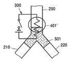
도4는 본 발명에 따른 마이크로 밸브의 제1실시예를 도시한 개략도이다.4 is a schematic view showing a first embodiment of a microvalve according to the present invention.
도5a 내지 도5f는 상기 도4에 도시된 마이크로 밸브의 작동에 따른 과도 상태를 도시한 개략도이다.5A to 5F are schematic diagrams showing a transient state according to the operation of the microvalve shown in FIG.
도6은 본 발명에 따른 마이크로 밸브의 변형 예를 도시한 개략도이다.6 is a schematic view showing a modification of the microvalve according to the present invention.
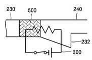
도7은 본 발명에 따른 마이크로 밸브의 제2실시예를 도시한 개략도이다.Fig. 7 is a schematic diagram showing a second embodiment of the microvalve according to the present invention.
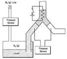
도8은 마이크로 밸브의 성능 시험 장치 구성을 도시한 개략도이다.8 is a schematic diagram showing a configuration of a performance test apparatus for a microvalve.
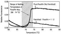
도9는 자성 왁스의 조성에 따른 용융 온도를 보이는 그래프이다.9 is a graph showing the melting temperature according to the composition of the magnetic wax.
*도면의 주요 부분에 대한 부호의 설명* Explanation of symbols for the main parts of the drawings
110: 마이크로 칩112: 마이크로 밸브110: microchip 112: microvalve
200: 기판210: 입구부200: substrate 210: entrance portion
220: 출구부250: 벤트부220: outlet 250: vent
300: 발열부401,401': 자기장 인가부300: heating unit 401,401 ': magnetic field applying unit
500: 자성 왁스 플러그501,501': 고체 자성 왁스 플러그500: magnetic wax plug 501,501 ': solid magnetic wax plug
502,502': 용융 자성 왁스 플러그502,502 ': Molten magnetic wax plug
본 발명은 마이크로 밸브 및 미세 유동 구조를 갖는 마이크로 칩에 관한 것으로, 상세하게는 미세 유동 구조에 구비되는 양 안정성(bi-stable)의 상 전이(phase change)식 마이크로 밸브 및 상기 마이크로 밸브 구조를 포함하는 마이크로 칩에 관한 것이다.The present invention relates to a microchip having a microvalve and a microfluidic structure, and more particularly, to a bi-stable phase change type microvalve provided in the microfluidic structure and the microvalve structure. To a microchip.
일반적으로 밸브는 배관에 연결하여 유체의 유량이나 압력을 제어하는 장치를 일컫는다. 최근에는 미세 유동 구조와 관련하여 마이크로 밸브 및 그 장치 등이 주목받고 있다. 이러한 현상은 특히 마이크로 화학분석시스템(μTAS)를 포함하는 생화학분야에서 현저하게 일어나고 있다. 신약개발과 연관된 μTAS, 임상진단시스템, DNA 등의 생체의학 연구분야는 물론 잉크젯 인쇄분야에서도 마이크로 밸브에 관한 관심도가 높다.In general, the valve refers to a device connected to the pipe to control the flow rate or pressure of the fluid. Recently, microvalve and its apparatus have been attracting attention in connection with the microfluidic structure. This is especially true in biochemistry, including microchemical analysis systems (μTAS). Microvalve interest is also high in inkjet printing as well as in biomedical research such as μTAS, clinical diagnostic systems, and DNA related to new drug development.
MEMS기술발전과 맥을 같이 하고 있는 마이크로 밸브, 소위 MEMS밸브는 기본적으로 기체, 액체를 포함하는 유체의 흐름을 허용하고, 제한하고, 차단하는 기능을 갖는 중요한 소자로서 마이크로 펌프와 더불어 미세 유동 구조의 핵심적 위치에 있다. 미세가공기술에 의해 제작되는 마이크로 밸브는 구동방식, 용도 등에 따라 구조가 매우 다양하고 수μm에서부터 약 1mm까지 다양한 크기를 갖는다.Micro valves, which are closely related to the development of MEMS technology, so-called MEMS valves are basically important elements that allow, restrict, and block the flow of fluids including gases and liquids. It is in a key position. The microvalve produced by the micromachining technique has a very diverse structure depending on the driving method and the use, and has a size ranging from several μm to about 1 mm.
다양한 종류의 마이크로 밸브들 중에서 상 전이 밸브가 연구되고 있다. 상 전이 밸브는 미세 유동 구조 내에 구비되어 고체 상으로 존재하면서 소정의 모드로 유체의 흐름을 조절하고, 어느 한 모드에서 다른 모드로 전환될 때에는 액체 상으로 상 전이되어 변위 또는 변형을 일으키는 유형의 밸브를 말한다. 이러한 상 전이 밸브는 미국특허 제 6679279호 및 미국특허공개공보 제2004/0219732호 등에서 제시된 바 있다. 이하, 첨부된 도면을 참조하면서 종래의 상 전이 밸브에 관해 설명한다.Among the various types of microvalve, a phase transfer valve is being studied. A phase transfer valve is a type of valve provided in the microfluidic structure that regulates the flow of a fluid in a predetermined mode while being in a solid phase and, when switching from one mode to another, causes a phase transition to a liquid phase to cause displacement or deformation. Say. Such a phase transfer valve has been presented in US Patent No. 6679279 and US Patent Publication No. 2004/0219732. Hereinafter, a conventional phase transfer valve will be described with reference to the accompanying drawings.
도1a 및 도1b는 종래의 상 전이 밸브의 일 예를 도시한 개략도이다. 도1a는 채널이 닫힌 닫힘 모드를, 도1b는 채널이 열린 열림 모드를 도시한다. 기판(20) 내에 마이크로 채널(21)이 형성되어 있고, 상기 채널(21)의 일측에는 우물(22)이 형성되어 있다. 상기 우물(22)의 상류측 채널(21) 내에는 고체왁스 플러그(40)가 구비된다. 고체왁스란 상온에서 고체상태이고 가열됨에 따라 유동성이 커지는 재료로서 파라핀 왁스 등이 이에 속한다.1A and 1B are schematic diagrams showing an example of a conventional phase transfer valve. FIG. 1A shows the channel in the closed mode and FIG. 1B shows the channel in the open mode. The
상기 고체왁스 플러그(40) 주위에는 선택적으로 발열 가능한 발열부(30)가 구비된다. 상기 도1a에 도시된 상태에서 상기 발열부(30)로부터 열이 발생하면, 상기 고체왁스 플러그(40)가 용융된다. 용융된 왁스(40')는 유체의 압력에 의해 상기 우물(22)에 흘러들어가 다시 응고된다. 그런데, 이러한 종래의 상 전이 밸브(101)는 밸브의 모드 전환이 비가역적이어서 밸브가 한 번 열리고 나면 재사용이 불가능 한 단점이 있다.A
도2a 및 도2b는 종래의 상 전이 밸브의 또다른 예를 도시한 개략도이다. 상기 도면에 도시된 유형의 상 전이 밸브(102)는 입구부(23), 출구부(24), 및 벤트(vent)부(25)가 만나는 'Y'자형 연결부를 가지고, 상기 Y자형 연결부로부터 벤트부로 이어지는 부분에는 발열부(30)를 갖는다. 도2a에 도시된 바와 같이 밸브(102)가 열린 모드일 때는, 고체왁스 플러그(42)가 상기 Y자형 연결부 내에 위치하고, 도2b에 도시된 바와 같이 밸브(102)가 닫힌 모드일 때는, 상기 고체왁스 플러그(42')가 벤트부(25) 내로 변위되어 위치한다.2A and 2B are schematic diagrams showing yet another example of a conventional phase transfer valve. A
모드 전환 시에는 상기 발열부(30)를 이용하여 상기 고체왁스 플러그(42)를 용융시키고, 상기 벤트부(25)의 일 측에 압축공기(air pressure) 및 진공(vacuum) 챔버(또는 펌프)를 선택적으로 연결하여 용융된 왁스를 이동시킨다. 따라서, 이러한 유형의 밸브(102)는 밸브의 구동을 위해 또 다른 밸브를 통해 고압 또는 진공의 챔버(또는 펌프)와 연결되어야 하는 단점이 있다.When the mode is switched, the
마이크로 단위의 소형화가 용이하고, 재사용이 가능한 미세 유동 구조를 제공하기 위해서는 상기한 종래의 상 전이 밸브들(101,102)이 가지는 단점들의 개선이 요구된다.In order to provide a micro flow structure that can be easily miniaturized and reusable, improvement of the disadvantages of the conventional
본 발명은 상기한 종래 기술의 단점들을 개선하기 위하여 제안된 것으로, 가역적인 모드 전환을 통해 재사용이 가능하도록 한 마이크로 밸브를 제공하는 데 그 목적이 있다.The present invention has been proposed to improve the above-mentioned disadvantages of the prior art, and an object thereof is to provide a microvalve that can be reused through reversible mode switching.
또한, 본 발명은 상기 마이크로 밸브가 적용된 미세 유동 구조를 갖는 마이크로 칩을 제공하는 데 그 목적이 있다.Another object of the present invention is to provide a microchip having a microfluidic structure to which the microvalve is applied.
본 발명에 따른 자성 왁스 플러그를 구비한 마이크로 밸브는,The microvalve with magnetic wax plug according to the present invention,
입구부와 출구부를 갖는 미세 유동 구조; 상기 입구부와 출구부가 만나는 소정 구간에 구비되는 것으로, 고체 상으로 존재하고 소정 온도보다 높은 온도에서 용융되어 자기장에 따라 가역적으로 이동함으로써 상기 유체의 이동을 조절하는 자성 왁스 플러그; 상기 소정 구간에 대응되게 구비되고, 밸브의 모드 전환 시에 상기 자성 왁스 플러그가 용융되도록 가열하는 발열부; 및 용융된 상기 자성 왁스 플러그가 도달할 위치에 선택적으로 자기장을 인가하는 자기장 인가부;를 포함한다.Microfluidic structure having an inlet and an outlet; A magnetic wax plug which is provided in a predetermined section where the inlet and the outlet meet, and which is present in the solid phase and melted at a temperature higher than a predetermined temperature to reversibly move according to a magnetic field to control the movement of the fluid; A heating unit provided corresponding to the predetermined section, and configured to heat the magnetic wax plug to be melted when switching the mode of the valve; And a magnetic field applying unit selectively applying a magnetic field to the molten magnetic wax plug to reach.
본 발명에 따른 자성 왁스 부재를 이용한 마이크로 칩은,The microchip using the magnetic wax member according to the present invention,
기판에 형성된 미세 구조를 이용하여 소량의 유체시료로 화학 반응 시험을 수행할 수 있도록 하는 마이크로 칩으로서, 미세한 경로를 통해 유체시료가 이동하도록 형성된 미세 유동 구조; 및 상기 미세 유동 구조의 소정 구간에 구비되는 것으로, 고체 상으로 존재하고 소정 온도보다 높은 온도에서 용융되어 자기장에 따라 가역적으로 이동함으로써 상기 유체시료의 이동을 조절하는 자성 왁스 부재;를 포함한다.A microchip for performing a chemical reaction test with a small amount of a fluid sample using a microstructure formed on a substrate, comprising: a microfluidic structure formed to move a fluid sample through a micro path; And a magnetic wax member provided in a predetermined section of the microfluidic structure, the magnetic wax member being in a solid phase and melting at a temperature higher than a predetermined temperature to reversibly move according to a magnetic field to control movement of the fluid sample.
또한, 본 발명에 따른 자성 왁스 부재를 이용한 마이크로 칩 유니트는,In addition, the microchip unit using the magnetic wax member according to the present invention,
기판에 형성된 미세 구조를 이용하여 소량의 유체시료로 화학 반응 시험을 수행할 수 있도록 하는 마이크로 칩과, 상기 마이크로 칩을 수용하고 구동하는 구 동 장치부로 이루어진 마이크로 칩 유니트로서,A microchip unit comprising a microchip for performing a chemical reaction test with a small amount of a fluid sample using a microstructure formed on a substrate, and a driving unit unit for receiving and driving the microchip.
상기 마이크로 칩은, 미세한 경로를 통해 유체시료가 이동하도록 형성된 미세 유동 구조; 및 상기 미세 유동 구조의 소정 구간에 구비되는 것으로, 고체 상으로 존재하고 소정 온도보다 높은 온도에서 용융되어 자기장에 따라 가역적으로 이동함으로써 상기 유체시료의 이동을 조절하는 자성 왁스 부재; 를 포함하고,The microchip may include a microfluidic structure formed to move a fluid sample through a microscopic path; And a magnetic wax member provided in a predetermined section of the microfluidic structure, the magnetic wax member being in a solid phase and melting at a temperature higher than a predetermined temperature to reversibly move according to a magnetic field to control the movement of the fluid sample. Including,
상기 구동 장치부는, 상기 미세 유동 구조의 소정 구간에 대응되게 구비되고, 상기 자성 왁스 부재가 용융되도록 가열하는 발열부; 및 용융된 상기 자성 왁스 부재가 도달할 위치에 선택적으로 자기장을 인가하는 자기장 인가부;를 포함하는 것을 특징으로 한다.The driving device unit may include a heating unit provided corresponding to a predetermined section of the microfluidic structure and heating the magnetic wax member to melt; And a magnetic field applying unit selectively applying a magnetic field to a position at which the molten magnetic wax member will reach.
또한, 상기 마이크로 밸브 및 마이크로 칩 유니트에 적용되는 유동 제어 방법은, 소정의 미세 유동 구조 내에 배치된 고체왁스에 열을 가하여 용융시키고, 용융된 상태에서 이를 이동시켜 상기 미세 유동 구조 내의 유체 흐름을 제어하는 유동 제어 방법으로서,In addition, the flow control method applied to the microvalve and the microchip unit, melts by applying heat to the solid wax disposed in a predetermined microfluidic structure, and moves it in the molten state to control the fluid flow in the microfluidic structure As a flow control method to
자성유체가 고체왁스와 균질 혼합된 자성 왁스를 마련하고 상기 자성 왁스를 상기 미세 유동 구조 내의 소정 구간에 배치하는 단계; 및 상기 소정 구간에 열을 가하여 상기 자성 왁스를 용융시키고, 용융된 자성 왁스가 도달할 위치에 자기장을 인가하여 상기 자성 왁스를 이동시킴으로써 유체의 흐름을 조절하는 단계;를 포함한다.Providing a magnetic wax in which a magnetic fluid is homogeneously mixed with the solid wax and disposing the magnetic wax in a predetermined section within the microfluidic structure; And applying heat to the predetermined section to melt the magnetic wax, and controlling the flow of the fluid by moving the magnetic wax by applying a magnetic field to a position where the molten magnetic wax will reach.
본 발명에 따른 자성 왁스 플러그를 구비한 마이크로 밸브는, 미세 유동 구조를 구비하고 그 미세 유동 구조 내에서 기체 또는 액체 등의 유동을 제어하여 어 떤 작업을 수행하는 다양한 분야에 적용될 수 있다. 특히, 생물학 또는 생화학 실험실의 구성요소들을 미세화하여 하나의 칩에 구현하는 랩온어칩(lab on a chip)에 적용되어, DNA 추출기술, DNA 증폭기술, DNA 검출기술, 세포 분리 실험기술, 세포 파괴기술, 세포독성 실험기술, HCS(High Contents Screening) 기술, 단일 생체분자 검출기술(single molecule detection) 등의 발전에 기여할 수 있다.The microvalve with magnetic wax plug according to the present invention can be applied to various fields having a microfluidic structure and controlling a flow of a gas or a liquid in the microfluidic structure to perform certain operations. In particular, it is applied to a lab on a chip that refines the components of a biology or biochemistry laboratory and implements them on a single chip. Technology, cytotoxicity test technology, HCS (High Contents Screening) technology, single molecule detection technology (single molecule detection) and the like can contribute.
또한, 본 발명에 따른 자성 왁스 부재를 이용한 마이크로 칩 및 마이크로 칩 유니트와 그 유동 제어 방법은 마이크로 밸브 뿐만아니라, 마이크로 펌프 등의 액츄에이터(actuator)에도 활용될 수 있을 것이다.In addition, the microchip and the microchip unit using the magnetic wax member and the flow control method thereof according to the present invention may be used not only in the microvalve but also in an actuator such as a micropump.
이하, 첨부된 도면을 참조하면서 본 발명에 따른 실시예를 상세히 설명한다. 도면에서 동일한 부호는 동일한 범주에 속하는 부분 또는 부재를 나타낸다.Hereinafter, with reference to the accompanying drawings will be described embodiments of the present invention; Like reference numerals in the drawings denote parts or members belonging to the same category.
도3은 본 발명에 따른 마이크로 밸브를 포함하는 마이크로 칩의 일 실시예를 도시한 개략도이다. 본 실시예에 따른 마이크로 칩(110)은 기판(200)에 형성된 소정의 미세 유동 구조를 갖는다. 상기 미세 유동 구조는 마이크로 채널들(210,220,250)과 마이크로 챔버(230) 등으로 이루어 질 수 있다. 일단에 시료 주입구(211)를 갖는 입구부(210)와 상기 마이크로 챔버(230)로 이어지는 출구부(220) 및 벤트(vent)부(250)는 'Y'자형 또는 'T'자형 연결부에 의해 서로 연결되어 있다. 상기 'Y'자형 연결부 내에는 자성 왁스 부재(500)가 구비되고, 상기 'Y'자형 연결부 주변에는 상기 자성 왁스 부재(500)를 가열하여 용융시킬 수 있는 발열부(300)가 구비된다.Figure 3 is a schematic diagram showing one embodiment of a microchip including a microvalve according to the present invention. The
이러한 마이크로 칩은 그 자체만으로 제공될 수 있고, 상기 마이크로 칩을 수용하고 이를 구동하는 구동 장치부와 함께 마이크로 칩 유니트로서 제공될 수도 있다.Such a microchip may be provided by itself, or may be provided as a microchip unit together with a drive unit for accommodating and driving the microchip.
상기 미세 유동 구조는 적어도 하나의 차원이 수 내지 수백 마이크로 미터의 크기를 갖는 구조로서 기체, 액체 등의 유체가 유통될 수 있는 채널, 챔버, 관 또는 이들의 조합으로 형성된 구조를 말하며, 밸브 또는 펌프 등의 액츄에이터를 포함할 수 있다. 미세 유동 구조는 일 예로서, 상기 도3에 도시된 바와 같이, 입구부, 출구부 및 벤트부가 한 점에서 서로 연결된 'Y'자형 또는 'T'자형 연결부를 가질 수 있으며, 이 외에도 다양한 형태를 가질 수 있다.The microfluidic structure refers to a structure having at least one dimension having a size of several to several hundred micrometers and formed of a channel, a chamber, a tube, or a combination thereof through which a fluid such as gas, liquid, and the like can be distributed, and a valve or a pump. Actuators, such as these may be included. As an example, the microfluidic structure may have a 'Y' or 'T' shape connection part connected to each other at one point as shown in FIG. 3, and the inlet part, the outlet part, and the vent part may have various shapes. Can have
상기 자성 왁스는 자성유체와 고체왁스의 균질 혼합물로서 상온에서 고체 상으로 존재하고, 고온에서 유동성을 갖는 액체 상으로 존재하며 자성을 띠어 자기장을 따라 유동하는 재료를 말한다. 상기 자성유체는 강자성(ferromagnetic property)을 띤 자성 입자와 상기 자성 입자의 표면을 둘러싸는 서팩턴트(surfactant) 및 캐리어(carrier)로 조성된 재료이다. 이때, 상기 캐리어는 일반적인 고체왁스와의 균질 혼합을 위해 탄화수소 계열인 것이 바람직하다. 상기 고체왁스는 탄화수소 계열로서 상온에서 고체 상으로 존재하고, 고온에서 유동성을 갖는 것으로 충분하며 일반적인 파라핀 왁스(paraffin wax)가 이에 해당될 수 있다.The magnetic wax is a homogeneous mixture of magnetic fluid and solid wax, which is present in the solid phase at room temperature, in the liquid phase having fluidity at high temperature, and refers to a material flowing along the magnetic field with magnetism. The magnetic fluid is a material composed of magnetic particles having ferromagnetic properties and surfacants and carriers surrounding the surfaces of the magnetic particles. In this case, the carrier is preferably a hydrocarbon-based for homogeneous mixing with a general solid wax. The solid wax is a hydrocarbon-based, present in the solid phase at room temperature, having sufficient fluidity at a high temperature, and may be a general paraffin wax.
자성유체와 파라핀 왁스가 혼합된 자성 왁스의 성질에 관하여는 <Markus Zahn, "Magnetic fluid and nanoparticle applications to nanotechnology", J. Nanoparticle Research 3:73-78, 2001> 에 'paraffin-based ferrofluid'라 하여 간략하게 언급된 바 있다.For the properties of magnetic waxes mixed with magnetic fluid and paraffin wax, Markus Zahn, "Magnetic fluid and nanoparticle applications to nanotechnology", J. Nanoparticle Research 3: 73-78, 2001, called "paraffin-based ferrofluid" It was briefly mentioned.
상기 발열부(300)는 상기 기판(200)에 설치되고 외부로부터 전기에너지를 공급받아 발열하는 저항 발열체일 수 있다. 또한, 반드시 기판(200)에 설치되어야 하는 것은 아니고, 상기 마이크로 칩(110)을 수용하고 이를 구동하는 구동 장치부(미도시)에 설치되어 상기 자성 왁스 부재(500) 주변으로 열을 전달시킬 수도 있다.The
상기 발열부(300)에 의해 용융된 자성 왁스 부재(500)는 선택된 위치에 자기장 인가부(미도시)로부터 인가된 자기장에 의해서 이동한다. 이동한 상기 용융 자성 왁스 부재는 다시 응고되고 이로써 새로운 모드를 이루면서 상기 미세 유동 구조 내의 유동을 조절한다.The
상기 자기장 인가부(미도시)는 마이크로 칩의 적어도 두 위치에 대하여 선택적으로 작용하는 솔레노이드부일 수 있고, 이 경우 상기 솔레노이드부들은 상기 마이크로 칩 자체에 설치되거나 상기 마이크로 칩을 수용하고 구동하는 구동 장치부에 설치될 수 있다. 또한 상기 자기장 인가부는 상기 마이크로 칩 외부에서 이동하며 영향을 미치는 적어도 하나의 영구자석일 수 있고, 이러한 영구자석 역시 상기 구동 장치부에 이동 가능하게 구비될 수 있음은 물론이다.The magnetic field applying unit (not shown) may be a solenoid unit selectively acting on at least two positions of the microchip, in which case the solenoid units are installed in the microchip itself or the driving unit unit receiving and driving the microchip. Can be installed on In addition, the magnetic field applying unit may be at least one permanent magnet that moves and affects the outside of the microchip, and the permanent magnet may also be provided to be movable to the driving unit.
도4는 본 발명에 따른 마이크로 밸브의 제1실시예를 도시한 개략도이다. 제1실시예에 따른 마이크로 밸브(112)는, 입구부(210)와 출구부(220) 및 벤트부(250)가 한 지점에서 만나는 'Y'자형 연결부를 갖는다. 상기 'Y'자형 연결부 또는 벤트부(250) 내에는 선택적으로 자성 왁스 부재(500)가 위치하고, 그 주변에는 상기 자성 왁스 부재(500)를 용융시킬 수 있는 발열부(300)가 구비된다. 상기 발열부(300)는 스위치를 구비하여 밸브의 모드 전환 시에만 선택적으로 발열할 수 있다.4 is a schematic view showing a first embodiment of a microvalve according to the present invention. The
또한, 상기 마이크로 밸브(112)는 용융된 자성 왁스 부재를 이동시킬 수 있도록 상기 'Y'자형 연결부 및 벤트부(250)에 선택적으로 자기장을 인가하는 자기장 인가부(401,401')를 구비한다. 상기 자기장 인가부는 상기 두 지점 사이를 이동할 수 있는 영구자석일 수 있고, 상기 두 지점에 각각 구비되어 선택적으로 자기장을 인가하는 솔레노이드부일 수도 있다.In addition, the
이하에서는 본 실시예에 따른 마이크로 밸브의 작동 과정을 설명함으로써 그 구성상의 특징 및 자성 왁스를 이용한 유동 제어방법을 상세히 설명한다. 도5a 내지 도5f는 상기 도4에 도시된 마이크로 밸브의 모드 전환 과정을 도시한 개략도이다. 상기 제1실시예에 따른 마이크로 밸브(112)는 상기 입구부(210)와 출구부(220)를 통한 유동을 차단하는 닫힘 모드와, 유동을 허용하는 열림 모드를 갖는다.Hereinafter, by describing the operation process of the microvalve according to the present embodiment will be described in detail the configuration features and flow control method using magnetic wax. 5A to 5F are schematic diagrams illustrating a mode switching process of the microvalve shown in FIG. 4. The
상기 도5a는 닫힘 모드를 나타낸다. 상온에서 고체 상의 자성 왁스 플러그(501)가 상기 'Y'자형 연결부의 중심을 막고 있다. 도5b 내지 도5d는 닫함 모드로부터 열림 모드로 전환하는 과정을 보여준다. 먼저 도5b에 도시된 바와 같이, 자기장 인가부(401')를 벤트부(250) 측에 위치시킨다. 다음 도5c에 도시된 바와 같이, 발열부(300)를 작동시켜 상기 자성 왁스 플러그를 가열한다. 용융되어 유동성이 생긴 용융 자성 왁스(502)는 자기장 인가부(401')를 따라 의해 상기 벤트부(250) 측으로 이동한다. 그 다음, 상기 발열부(300)의 작동을 멈추고 냉각시키면 도5d에 도시된 바와 같이 자성 왁스가 다시 응고되어 벤트부(250) 내에 자성 왁스 플러그(501')가 위치하게 되고, 이로써 열림 모드를 이루어 입구부(210)와 출구부(220) 사이의 유동을 허용하게 된다.Figure 5a shows a closed mode. At room temperature, a solid
도5e 내지 도5f는 열림 모드에서 닫힘 모드로 전환하는 과정을 보여준다. 먼저 도5e에 도시된 바와 같이, 자기장 인가부(401)를 상기 'Y'자형 연결부의 중심부에 위치시킨다. 다음 상기 도5f에 도시된 바와 같이 상기 발열부(300)를 작동시켜 상기 자성 왁스 플러그를 용융시킨다. 용융 자성 왁스(502')는 상기 자기장 인가부(401)을 따라 'Y'자형 연결부로 이동한다. 그 다음, 상기 발열부(300)의 작동을 멈추고 냉각시키면 상기 도5a에 도시된 닫힘 모드로 다시 돌아간다.5e to 5f show a process of switching from the open mode to the closed mode. First, as shown in FIG. 5E, the magnetic
상기 발열부에 의한 자성 왁스 플러그의 용융과 자기장 인가부에 의한 자기장 인가의 시간적인 순서는, 용융된 자성 왁스의 불필요한 유동을 방지하기 위해 자기장 인가가 앞서는 것이 바람직하다. 다만, 이에 한정되는 것은 아니며 그 반대의 순서도 가능하고 동시에 수행되는 것도 가능하다.The temporal order of melting the magnetic wax plug by the heat generating unit and applying the magnetic field by the magnetic field applying unit is preferably preceded by the magnetic field application in order to prevent unnecessary flow of the molten magnetic wax. However, the present invention is not limited thereto, and the reverse order may be possible and may be performed simultaneously.
도6은 본 발명에 따른 마이크로 밸브의 변형 예를 도시한 개략도이다. 본 변형 예는 입구부(210), 출구부(220) 및 벤트부(250)로 이루어진 미세 유동 구조내에 고체왁스 플러그(42)를 구비하고, 상기 고체왁스 플러그(42)를 용융시킬 수 있는 발열부(300)를 구비한다. 상기 벤트부(250) 내에는 상기 고체왁스 플러그(42)와 인접하게 자성유체(450)를 주입하고, 상기 자성유체(450)를 이동시킬 수 있는 자기장 인가부(400)를 구비하여 상기 고체왁스 플러그(42)가 용융되었을 때 상기 자성유체(450)를 이동시켜 상기 고체왁스 플러그(42)의 위치를 변화시키도록 한다.6 is a schematic view showing a modification of the microvalve according to the present invention. This modification is provided with a
도7은 본 발명에 따른 마이크로 밸브의 제2실시예를 도시한 개략도이다. 본 실시예에 따른 밸브는 직선상으로 배치된 입구부(230)와 출구부(240)를 가지고, 입구부(230)와 출구부(240)가 만나는 부분의 저면에 상기 입구부(230)로부터 경사지 게 형성된 우물부(232)를 갖는다. 닫힘 모드일 때는 상기 우물부(232)의 상류측인 입구부(230) 내에 자성 왁스 플러그(500)가 위치한다.Fig. 7 is a schematic diagram showing a second embodiment of the microvalve according to the present invention. The valve according to the present embodiment has an
열림 모드로 전환할 때에는 발열부(300)를 작동시켜 상기 자성 왁스 플러그(500)를 용융시키면 용융 자성 왁스가 경사면을 따라 우물부(232)에 담겨지면서 상기 입구부(230)와 출구부(240) 사이의 유동을 허용한다. 반대로 열림 모드에서 닫힘 모드로 전환할 때에도 자기장을 인가하여 용융 자성 왁스가 상기 경사면을 따라 상류측으로 이동하도록 할 수 있다.When switching to the open mode, the
도8은 마이크로 밸브의 성능 시험 장치 구성을 도시한 개략도이다. 상기 도면에 도시된 장치로 본 발명에 따른 마이크로 밸브가 닫힘 모드일 때의 허용압력을 측정하였다. 자성유체와 파라핀 왁스를 1:2의 부피비로 혼합하였고, 상기 자성유체로는 미국 Ferrotech사의 APG E18, 138 Gauss를, 상기 파라핀 왁스로는 미국 Fluka사의 76232, sp 68-74℃를 사용하였다. 자성 왁스 플러그의 부피는 0.2㎕로 하였다. 이때, 본 발명의 제1실시예에 따른 마이크로 밸브의 최대 허용압력은 대략 50 Psi에 이름을 확인할 수 있었다.8 is a schematic diagram showing a configuration of a performance test apparatus for a microvalve. The allowable pressure was measured when the microvalve according to the present invention was in the closed mode with the apparatus shown in the figure. Magnetic fluid and paraffin wax were mixed in a volume ratio of 1: 2, and APG E18, 138 Gauss, Ferrotech, USA was used as the magnetic fluid, 76232, sp 68-74 ° C, Fluka, USA, was used as the paraffin wax. The volume of the magnetic wax plug was 0.2 µl. At this time, the maximum allowable pressure of the microvalve according to the first embodiment of the present invention was found to be approximately 50 Psi.
도9는 자성 왁스의 조성에 따른 용융 온도를 보이는 그래프이다. 위의 실험에 사용된 자성 왁스 플러그와 같은 조성을 갖는 자성 왁스와 순수한 파라핀 왁스를 대상으로하여 온도변화에 따른 광학적 성질 변화를 측정함으로써 이들의 용융 온도를 비교하였다. 상기 그래프에서 어둡게 표시된 온도 영역에서 자성 왁스의 상 전이가 일어남을 알 수 있다. 다만, 자성 왁스의 상 전이 온도는 그래프에 표시된 영역에 한정되는 것이 아니고, 혼합된 고체왁스의 종류에 따라서 달라질 수 있다. 이점을 이용하여 유동을 조절하고자 하는 유체의 종류 및 사용되는 온도 조건에 따라 다양한 상 전이 온도를 갖는 자성 왁스를 제공할 수 있다.9 is a graph showing the melting temperature according to the composition of the magnetic wax. The melting temperature of the magnetic waxes and the pure paraffin waxes having the same composition as the magnetic wax plugs used in the above experiments were measured by measuring the optical property change according to the temperature change. It can be seen that the phase transition of the magnetic wax occurs in the dark region of the temperature indicated in the graph. However, the phase transition temperature of the magnetic wax is not limited to the region shown in the graph, and may vary depending on the type of the mixed solid wax. This can be used to provide magnetic waxes having various phase transition temperatures depending on the type of fluid to be controlled and the temperature conditions used.
이하, 자성 왁스를 이용한 유동 제어 방법에 관하여 설명한다.Hereinafter, a flow control method using magnetic wax will be described.
소정의 미세 유동 구조 내에 배치된 고체왁스에 열을 가하여 용융시키고, 용융된 상태에서 이를 이동시켜 상기 미세 유동 구조 내의 유체 흐름을 제어하는 유동 제어 방법에 있어서, 본 발명에 따른 유동 제어 방법은, 먼저 자성유체가 고체왁스와 균질 혼합된 자성 왁스를 마련하고 상기 자성 왁스를 상기 미세 유동 구조 내의 소정 구간에 배치한다. 이는 본 발명에 따른 마이크로 밸브 또는 마이크로 칩 등의 제조 과정에서 이루어질 수 있다.In the flow control method for controlling the fluid flow in the microfluidic structure by applying heat to the solid wax disposed in a predetermined microfluidic structure and moving it in a molten state, the flow control method according to the present invention, A magnetic fluid provides a magnetic wax homogeneously mixed with a solid wax and places the magnetic wax in a predetermined section within the microfluidic structure. This can be done in the manufacturing process of the microvalve or microchip according to the present invention.
다음으로 미세 유동 구조 내의 유동을 조절하고자 할 때는, 상기 소정 구간에 열을 가하여 상기 자성 왁스를 용융시키고, 용융된 자성 왁스가 도달할 위치에 자기장을 인가하여 상기 자성 왁스를 이동시킨다. 자성 왁스를 용융시키는 것과 소정 위치에 자기장을 인가하는 것은 하나의 순서로 한정되는 것은 아니고, 둘 중 어느 하나의 과정이 앞서거나 동시에 수행될 수도 있다.Next, in order to control the flow in the microfluidic structure, heat is applied to the predetermined section to melt the magnetic wax, and the magnetic wax is moved by applying a magnetic field to the position where the molten magnetic wax will reach. Melting the magnetic wax and applying the magnetic field at a predetermined position are not limited to one order, and either process may be performed in advance or simultaneously.
이상에서 본 발명에 따른 바람직한 실시예가 설명되었으나, 이는 예시적인 것에 불과하며, 당해 기술분야에서 통상의 지식을 가진 자라면 이로부터 다양한 변형 및 균등한 타 실시예가 가능하다는 점을 이해할 수 있을 것이다. 따라서, 본 발명의 보호범위는 첨부된 특허청구범위에 의해서 정해져야 할 것이다.Although the preferred embodiment according to the present invention has been described above, this is merely exemplary, and it will be understood by those skilled in the art that various modifications and equivalent other embodiments are possible. Therefore, the protection scope of the present invention should be defined by the appended claims.
상기한 본 발명에 의한 마이크로 밸브, 마이크로 칩, 마이크로 칩 유니트 및 미세 유동 제어 방법은 미세 유동의 조절을 위해 요구되는 장치 구성을 단순화하고, 가역적인 모드 전환을 통해 장치의 재사용이 가능하도록 하는 효과가 있다.The microvalve, the microchip, the microchip unit and the microfluidic control method according to the present invention have the effect of simplifying the device configuration required for the control of the microfluidic and reusing the device through the reversible mode switching. have.
Claims (21)
Translated fromKoreanPriority Applications (5)
| Application Number | Priority Date | Filing Date | Title |
|---|---|---|---|
| KR1020050027829AKR100668335B1 (en) | 2005-04-02 | 2005-04-02 | Micro valve with magnetic wax plug and flow control method using magnetic wax |
| US11/396,764US7478792B2 (en) | 2005-04-02 | 2006-04-03 | Microvalve having magnetic wax plug and flux control method using magnetic wax |
| US12/277,780US7874305B2 (en) | 2005-04-02 | 2008-11-25 | Microvalve having magnetic wax plug and flux control method using magnetic wax |
| US12/968,752US8167265B2 (en) | 2005-04-02 | 2010-12-15 | Microvalve having magnetic wax plug and flux control method using magnetic wax |
| US13/402,271US8403292B2 (en) | 2005-04-02 | 2012-02-22 | Microvalve having magnetic wax plug and flux control method using magnetic wax |
Applications Claiming Priority (1)
| Application Number | Priority Date | Filing Date | Title |
|---|---|---|---|
| KR1020050027829AKR100668335B1 (en) | 2005-04-02 | 2005-04-02 | Micro valve with magnetic wax plug and flow control method using magnetic wax |
Publications (2)
| Publication Number | Publication Date |
|---|---|
| KR20060105234A KR20060105234A (en) | 2006-10-11 |
| KR100668335B1true KR100668335B1 (en) | 2007-01-12 |
Family
ID=37068896
Family Applications (1)
| Application Number | Title | Priority Date | Filing Date |
|---|---|---|---|
| KR1020050027829AExpired - Fee RelatedKR100668335B1 (en) | 2005-04-02 | 2005-04-02 | Micro valve with magnetic wax plug and flow control method using magnetic wax |
Country Status (2)
| Country | Link |
|---|---|
| US (4) | US7478792B2 (en) |
| KR (1) | KR100668335B1 (en) |
Families Citing this family (44)
| Publication number | Priority date | Publication date | Assignee | Title |
|---|---|---|---|---|
| KR100668335B1 (en)* | 2005-04-02 | 2007-01-12 | 삼성전자주식회사 | Micro valve with magnetic wax plug and flow control method using magnetic wax |
| EP1884284A1 (en)* | 2006-08-04 | 2008-02-06 | Samsung Electronics Co., Ltd. | Closing valve unit and reaction apparatus having closing valve |
| US8464760B2 (en)* | 2006-08-16 | 2013-06-18 | Samsung Electronic Co., Ltd. | Valve unit, reaction apparatus with the same, and method of forming valve in channel |
| KR101343034B1 (en)* | 2006-09-05 | 2013-12-18 | 삼성전자 주식회사 | Centrifugal microfluidic device for target protein detection and microfluidic system comprising the same |
| KR101422572B1 (en)* | 2006-09-05 | 2014-07-30 | 삼성전자주식회사 | Centrifugal-force microfluidic device for nucleic acid detection and microfluidic system including the same |
| KR100851980B1 (en)* | 2006-09-05 | 2008-08-12 | 삼성전자주식회사 | Centrifugal force-based microfluidic device having a thermally active unit, a microfluidic system including the same, and a method of driving the microfluidic system |
| US7951333B2 (en)* | 2006-09-05 | 2011-05-31 | Samsung Electronics Co., Ltd. | Centrifugal force-based microfluidic device for protein detection and microfluidic system including the same |
| KR100846501B1 (en)* | 2006-11-09 | 2008-07-17 | 삼성전자주식회사 | Valve unit and fluid treatment device having same |
| KR20080073934A (en)* | 2007-02-07 | 2008-08-12 | 삼성전자주식회사 | Valve Filler And Valve Unit With The Same |
| KR20080084049A (en)* | 2007-03-14 | 2008-09-19 | 삼성전자주식회사 | Pump unit and centrifugal force-based microfluidic system |
| US7980272B2 (en)* | 2007-06-21 | 2011-07-19 | Samsung Electronics Co., Ltd. | Microfluidic valve, method of manufacturing the same, and microfluidic device comprising the microfluidic valve |
| EP2208210B1 (en)* | 2007-10-12 | 2012-02-15 | Eriksen Electric Power Systems AS | Inductive coupler connector |
| US20100051517A1 (en)* | 2008-08-29 | 2010-03-04 | Schlumberger Technology Corporation | Actuation and pumping with field-responsive fluids |
| KR101578149B1 (en)* | 2009-01-29 | 2015-12-17 | 삼성전자주식회사 | Valve unit for microfluid control and manufacturing method thereof |
| JP5819290B2 (en) | 2009-06-03 | 2015-11-24 | コーニンクレッカ フィリップス エヌ ヴェKoninklijke Philips N.V. | Valve with material with variable degree of permeability |
| KR101130698B1 (en)* | 2009-11-03 | 2012-04-02 | 삼성전자주식회사 | Valve unit, microfluidic device including the same, and driving method of the valve unit |
| EP2369343B1 (en)* | 2010-03-15 | 2012-01-18 | Boehringer Ingelheim International Gmbh | Device and method for manipulating or examining a liquid sample |
| MX2013000147A (en)* | 2010-06-23 | 2015-12-07 | Greenward Company L L C | Flow regulating applied magnetic envelope. |
| US9850845B2 (en) | 2011-12-07 | 2017-12-26 | Agility Fuel Systems, Inc. | Systems and methods for monitoring and controlling fuel systems |
| DE102012005992B3 (en)* | 2012-03-23 | 2013-07-11 | Karlsruher Institut für Technologie | Bistable actuator, actuator assembly, method of actuation and use |
| US9157460B2 (en)* | 2012-06-05 | 2015-10-13 | Toyota Motor Engineering & Manufacturing North America, Inc. | Controlling a fluid flow with a magnetic field |
| WO2014036437A1 (en)* | 2012-08-30 | 2014-03-06 | Massachusetts Eye & Ear Infirmary | Ferromagnetic valves |
| US9623409B2 (en) | 2013-03-11 | 2017-04-18 | Cue Inc. | Cartridges, kits, and methods for enhanced mixing for detection and quantification of analytes |
| US10545161B2 (en) | 2013-03-11 | 2020-01-28 | Cue Health Inc. | Systems and methods for detection and quantification of analytes |
| KR102557135B1 (en) | 2013-03-11 | 2023-07-19 | 큐 헬스 인코퍼레이티드 | Systems and methods for detection and quantification of analytes |
| DE102013205412A1 (en)* | 2013-03-27 | 2014-10-02 | Robert Bosch Gmbh | Normally closed valve for microfluidic components made of a polymer layer system and method |
| USD745423S1 (en) | 2014-05-12 | 2015-12-15 | Cue Inc. | Automated analyzer test cartridge and sample collection device for analyte detection |
| US9995411B1 (en)* | 2014-07-16 | 2018-06-12 | National Technology & Engineering Solutions Of Sandia, Llc | High-temperature, adhesive-based microvalves and uses thereof |
| AU2016296589B2 (en) | 2015-07-17 | 2021-11-18 | Cue Health Inc. | Systems and methods for enhanced detection and quantification of analytes |
| WO2017070165A1 (en) | 2015-10-19 | 2017-04-27 | The Methodist Hospital | Method and apparatus for the fail-safe termination of in vivo drug delivery from an implantable drug delivery system |
| WO2018102727A1 (en) | 2016-12-01 | 2018-06-07 | Alfadhel Ahmed | Capsule, in-line magnetic valve system and method |
| WO2018140540A1 (en) | 2017-01-25 | 2018-08-02 | Cue Health Inc. | Systems and methods for enhanced detection and quantification of analytes |
| US11491489B2 (en) | 2017-12-28 | 2022-11-08 | Stmicroelectronics S.R.L. | Microfluidic connector group, microfluidic device and manufacturing process thereof, in particular for a cartridge for sample preparation and molecule analysis |
| US11110457B2 (en) | 2017-12-28 | 2021-09-07 | Stmicroelectronics S.R.L. | Analysis unit for a transportable microfluidic device, in particular for sample preparation and molecule analysis |
| US11511278B2 (en) | 2017-12-28 | 2022-11-29 | Stmicroelectronics S.R.L. | Solid reagent containment unit, in particular for a portable microfluidic device for sample preparation and molecule analysis |
| US11717825B2 (en) | 2017-12-28 | 2023-08-08 | Stmicroelectronics S.R.L. | Magnetically controllable valve and portable microfluidic device having a magnetically controllable valve, in particular cartridge for sample preparation and molecule analysis |
| US11278897B2 (en)* | 2017-12-28 | 2022-03-22 | Stmicroelectronics S.R.L. | Cartridge for sample preparation and molecule analysis, cartridge control machine, sample preparation system and method using the cartridge |
| WO2019187294A1 (en)* | 2018-03-30 | 2019-10-03 | 富士フイルム株式会社 | Tip, mixing device, and mixing method |
| US10738903B2 (en)* | 2018-08-29 | 2020-08-11 | International Business Machines Corporation | Microfluidic relief valve |
| US11498270B2 (en)* | 2018-11-21 | 2022-11-15 | Toyota Motor Engineering & Manufacturing North America, Inc. | Programmable matter |
| US12103000B2 (en)* | 2020-04-10 | 2024-10-01 | The Regents Of The University Of California | Microfluidic phase-change membrane microvalves |
| CN114634869A (en)* | 2022-03-21 | 2022-06-17 | 诺美纳瑞(广州)医疗技术有限公司 | PCR detection system |
| CN114672405A (en)* | 2022-03-21 | 2022-06-28 | 诺美纳瑞(广州)医疗技术有限公司 | PCR amplification detection integrated system and PCR reaction control method thereof |
| CN119137402A (en)* | 2022-05-19 | 2024-12-13 | Asml荷兰有限公司 | Cryovalve in target material generation device |
Family Cites Families (13)
| Publication number | Priority date | Publication date | Assignee | Title |
|---|---|---|---|---|
| DE19749011A1 (en)* | 1996-11-19 | 1998-05-20 | Lang Volker | Micro=valve for one time use has opening closed by plug mounted on resistance plate |
| US6375901B1 (en) | 1998-06-29 | 2002-04-23 | Agilent Technologies, Inc. | Chemico-mechanical microvalve and devices comprising the same |
| SE9902474D0 (en)* | 1999-06-30 | 1999-06-30 | Amersham Pharm Biotech Ab | Polymer valves |
| US6408884B1 (en)* | 1999-12-15 | 2002-06-25 | University Of Washington | Magnetically actuated fluid handling devices for microfluidic applications |
| US6561479B1 (en)* | 2000-08-23 | 2003-05-13 | Micron Technology, Inc. | Small scale actuators and methods for their formation and use |
| US6575188B2 (en)* | 2001-07-26 | 2003-06-10 | Handylab, Inc. | Methods and systems for fluid control in microfluidic devices |
| US6679279B1 (en) | 2002-07-10 | 2004-01-20 | Motorola, Inc. | Fluidic valve having a bi-phase valve element |
| US7195036B2 (en) | 2002-11-04 | 2007-03-27 | The Regents Of The University Of Michigan | Thermal micro-valves for micro-integrated devices |
| US7059352B2 (en)* | 2004-03-31 | 2006-06-13 | Lifescan Scotland | Triggerable passive valve for use in controlling the flow of fluid |
| US7694694B2 (en)* | 2004-05-10 | 2010-04-13 | The Aerospace Corporation | Phase-change valve apparatuses |
| KR100668335B1 (en)* | 2005-04-02 | 2007-01-12 | 삼성전자주식회사 | Micro valve with magnetic wax plug and flow control method using magnetic wax |
| EP1884284A1 (en)* | 2006-08-04 | 2008-02-06 | Samsung Electronics Co., Ltd. | Closing valve unit and reaction apparatus having closing valve |
| US7980272B2 (en)* | 2007-06-21 | 2011-07-19 | Samsung Electronics Co., Ltd. | Microfluidic valve, method of manufacturing the same, and microfluidic device comprising the microfluidic valve |
- 2005
- 2005-04-02KRKR1020050027829Apatent/KR100668335B1/ennot_activeExpired - Fee Related
- 2006
- 2006-04-03USUS11/396,764patent/US7478792B2/enactiveActive
- 2008
- 2008-11-25USUS12/277,780patent/US7874305B2/enactiveActive
- 2010
- 2010-12-15USUS12/968,752patent/US8167265B2/ennot_activeExpired - Fee Related
- 2012
- 2012-02-22USUS13/402,271patent/US8403292B2/enactiveActive
Also Published As
| Publication number | Publication date |
|---|---|
| US7478792B2 (en) | 2009-01-20 |
| US20120168016A1 (en) | 2012-07-05 |
| US7874305B2 (en) | 2011-01-25 |
| US8167265B2 (en) | 2012-05-01 |
| US20060219308A1 (en) | 2006-10-05 |
| KR20060105234A (en) | 2006-10-11 |
| US20110079289A1 (en) | 2011-04-07 |
| US8403292B2 (en) | 2013-03-26 |
| US20090071542A1 (en) | 2009-03-19 |
Similar Documents
| Publication | Publication Date | Title |
|---|---|---|
| KR100668335B1 (en) | Micro valve with magnetic wax plug and flow control method using magnetic wax | |
| US7195036B2 (en) | Thermal micro-valves for micro-integrated devices | |
| EP1967267B1 (en) | Microfluidic valve filler and valve unit including the same | |
| EP1425528B1 (en) | Methods and systems for fluid control in microfluidics devices | |
| JP3921233B2 (en) | Fluid chip, fluid movement control method using the same, and chemical reaction device | |
| US8066031B2 (en) | Electro-hydraulic devices | |
| US6415821B2 (en) | Magnetically actuated fluid handling devices for microfluidic applications | |
| US8240336B2 (en) | Phase-change valve apparatuses | |
| EP1920843B1 (en) | Valve unit, microfluidic device with the valve unit, and microfluidic substrate | |
| US8051878B2 (en) | Magnetic valves for performing multi-dimensional assays using one microfluidic chip | |
| US20100165784A1 (en) | Instrument with microfluidic chip | |
| US7650910B2 (en) | Electro-hydraulic valve apparatuses | |
| Sesen et al. | Thermally-actuated microfluidic membrane valve for point-of-care applications | |
| JP4579490B2 (en) | Device for parallel synchronous injection for sequential injection of various reactants | |
| Park et al. | Reusable EWOD-based microfluidic system for active droplet generation | |
| Oh et al. | A phase change microvalve using a meltable magnetic material: Ferro-wax | |
| Ahamed et al. | Electrowetting on Dielectric (EWOD)-based thermo-responsive microvalve for interfacing droplet flow with continuous flow | |
| Liu et al. | Thermal-Actuated Paraffin Microvalves | |
| Yamanishi et al. | On-demand and size-controlled production of emulsion droplet in microfludic devices | |
| JP2009178632A (en) | Fine channel with microvalve |
Legal Events
| Date | Code | Title | Description |
|---|---|---|---|
| A201 | Request for examination | ||
| PA0109 | Patent application | St.27 status event code:A-0-1-A10-A12-nap-PA0109 | |
| PA0201 | Request for examination | St.27 status event code:A-1-2-D10-D11-exm-PA0201 | |
| R17-X000 | Change to representative recorded | St.27 status event code:A-3-3-R10-R17-oth-X000 | |
| PN2301 | Change of applicant | St.27 status event code:A-3-3-R10-R13-asn-PN2301 St.27 status event code:A-3-3-R10-R11-asn-PN2301 | |
| PN2301 | Change of applicant | St.27 status event code:A-3-3-R10-R13-asn-PN2301 St.27 status event code:A-3-3-R10-R11-asn-PN2301 | |
| E902 | Notification of reason for refusal | ||
| PE0902 | Notice of grounds for rejection | St.27 status event code:A-1-2-D10-D21-exm-PE0902 | |
| PG1501 | Laying open of application | St.27 status event code:A-1-1-Q10-Q12-nap-PG1501 | |
| P11-X000 | Amendment of application requested | St.27 status event code:A-2-2-P10-P11-nap-X000 | |
| P13-X000 | Application amended | St.27 status event code:A-2-2-P10-P13-nap-X000 | |
| E701 | Decision to grant or registration of patent right | ||
| PE0701 | Decision of registration | St.27 status event code:A-1-2-D10-D22-exm-PE0701 | |
| GRNT | Written decision to grant | ||
| PR0701 | Registration of establishment | St.27 status event code:A-2-4-F10-F11-exm-PR0701 | |
| PR1002 | Payment of registration fee | St.27 status event code:A-2-2-U10-U11-oth-PR1002 Fee payment year number:1 | |
| PG1601 | Publication of registration | St.27 status event code:A-4-4-Q10-Q13-nap-PG1601 | |
| PR1001 | Payment of annual fee | St.27 status event code:A-4-4-U10-U11-oth-PR1001 Fee payment year number:4 | |
| PR1001 | Payment of annual fee | St.27 status event code:A-4-4-U10-U11-oth-PR1001 Fee payment year number:5 | |
| P14-X000 | Amendment of ip right document requested | St.27 status event code:A-5-5-P10-P14-nap-X000 | |
| P16-X000 | Ip right document amended | St.27 status event code:A-5-5-P10-P16-nap-X000 | |
| Q16-X000 | A copy of ip right certificate issued | St.27 status event code:A-4-4-Q10-Q16-nap-X000 | |
| PR1001 | Payment of annual fee | St.27 status event code:A-4-4-U10-U11-oth-PR1001 Fee payment year number:6 | |
| R18-X000 | Changes to party contact information recorded | St.27 status event code:A-5-5-R10-R18-oth-X000 | |
| FPAY | Annual fee payment | Payment date:20121228 Year of fee payment:7 | |
| PR1001 | Payment of annual fee | St.27 status event code:A-4-4-U10-U11-oth-PR1001 Fee payment year number:7 | |
| FPAY | Annual fee payment | Payment date:20131230 Year of fee payment:8 | |
| PR1001 | Payment of annual fee | St.27 status event code:A-4-4-U10-U11-oth-PR1001 Fee payment year number:8 | |
| FPAY | Annual fee payment | Payment date:20141223 Year of fee payment:9 | |
| PR1001 | Payment of annual fee | St.27 status event code:A-4-4-U10-U11-oth-PR1001 Fee payment year number:9 | |
| FPAY | Annual fee payment | Payment date:20151229 Year of fee payment:10 | |
| PR1001 | Payment of annual fee | St.27 status event code:A-4-4-U10-U11-oth-PR1001 Fee payment year number:10 | |
| FPAY | Annual fee payment | Payment date:20161228 Year of fee payment:11 | |
| PR1001 | Payment of annual fee | St.27 status event code:A-4-4-U10-U11-oth-PR1001 Fee payment year number:11 | |
| LAPS | Lapse due to unpaid annual fee | ||
| PC1903 | Unpaid annual fee | St.27 status event code:A-4-4-U10-U13-oth-PC1903 Not in force date:20180109 Payment event data comment text:Termination Category : DEFAULT_OF_REGISTRATION_FEE | |
| PC1903 | Unpaid annual fee | St.27 status event code:N-4-6-H10-H13-oth-PC1903 Ip right cessation event data comment text:Termination Category : DEFAULT_OF_REGISTRATION_FEE Not in force date:20180109 |