KR100668178B1 - Flexible reflective insulation structure - Google Patents
Flexible reflective insulation structureDownload PDFInfo
- Publication number
- KR100668178B1 KR100668178B1KR1020027010393AKR20027010393AKR100668178B1KR 100668178 B1KR100668178 B1KR 100668178B1KR 1020027010393 AKR1020027010393 AKR 1020027010393AKR 20027010393 AKR20027010393 AKR 20027010393AKR 100668178 B1KR100668178 B1KR 100668178B1
- Authority
- KR
- South Korea
- Prior art keywords
- layer
- structure according
- fiber
- insulation structure
- metal layer
- Prior art date
- Legal status (The legal status is an assumption and is not a legal conclusion. Google has not performed a legal analysis and makes no representation as to the accuracy of the status listed.)
- Expired - Fee Related
Links
Images


Classifications
- B—PERFORMING OPERATIONS; TRANSPORTING
- B32—LAYERED PRODUCTS
- B32B—LAYERED PRODUCTS, i.e. PRODUCTS BUILT-UP OF STRATA OF FLAT OR NON-FLAT, e.g. CELLULAR OR HONEYCOMB, FORM
- B32B15/00—Layered products comprising a layer of metal
- B32B15/14—Layered products comprising a layer of metal next to a fibrous or filamentary layer
- B—PERFORMING OPERATIONS; TRANSPORTING
- B32—LAYERED PRODUCTS
- B32B—LAYERED PRODUCTS, i.e. PRODUCTS BUILT-UP OF STRATA OF FLAT OR NON-FLAT, e.g. CELLULAR OR HONEYCOMB, FORM
- B32B27/00—Layered products comprising a layer of synthetic resin
- B32B27/30—Layered products comprising a layer of synthetic resin comprising vinyl (co)polymers; comprising acrylic (co)polymers
- B32B27/304—Layered products comprising a layer of synthetic resin comprising vinyl (co)polymers; comprising acrylic (co)polymers comprising vinyl halide (co)polymers, e.g. PVC, PVDC, PVF, PVDF
- B—PERFORMING OPERATIONS; TRANSPORTING
- B32—LAYERED PRODUCTS
- B32B—LAYERED PRODUCTS, i.e. PRODUCTS BUILT-UP OF STRATA OF FLAT OR NON-FLAT, e.g. CELLULAR OR HONEYCOMB, FORM
- B32B27/00—Layered products comprising a layer of synthetic resin
- B32B27/32—Layered products comprising a layer of synthetic resin comprising polyolefins
- B—PERFORMING OPERATIONS; TRANSPORTING
- B32—LAYERED PRODUCTS
- B32B—LAYERED PRODUCTS, i.e. PRODUCTS BUILT-UP OF STRATA OF FLAT OR NON-FLAT, e.g. CELLULAR OR HONEYCOMB, FORM
- B32B27/00—Layered products comprising a layer of synthetic resin
- B32B27/34—Layered products comprising a layer of synthetic resin comprising polyamides
- B—PERFORMING OPERATIONS; TRANSPORTING
- B32—LAYERED PRODUCTS
- B32B—LAYERED PRODUCTS, i.e. PRODUCTS BUILT-UP OF STRATA OF FLAT OR NON-FLAT, e.g. CELLULAR OR HONEYCOMB, FORM
- B32B5/00—Layered products characterised by the non- homogeneity or physical structure, i.e. comprising a fibrous, filamentary, particulate or foam layer; Layered products characterised by having a layer differing constitutionally or physically in different parts
- B32B5/02—Layered products characterised by the non- homogeneity or physical structure, i.e. comprising a fibrous, filamentary, particulate or foam layer; Layered products characterised by having a layer differing constitutionally or physically in different parts characterised by structural features of a fibrous or filamentary layer
- B32B5/022—Non-woven fabric
- B—PERFORMING OPERATIONS; TRANSPORTING
- B32—LAYERED PRODUCTS
- B32B—LAYERED PRODUCTS, i.e. PRODUCTS BUILT-UP OF STRATA OF FLAT OR NON-FLAT, e.g. CELLULAR OR HONEYCOMB, FORM
- B32B5/00—Layered products characterised by the non- homogeneity or physical structure, i.e. comprising a fibrous, filamentary, particulate or foam layer; Layered products characterised by having a layer differing constitutionally or physically in different parts
- B32B5/02—Layered products characterised by the non- homogeneity or physical structure, i.e. comprising a fibrous, filamentary, particulate or foam layer; Layered products characterised by having a layer differing constitutionally or physically in different parts characterised by structural features of a fibrous or filamentary layer
- B32B5/024—Woven fabric
- B—PERFORMING OPERATIONS; TRANSPORTING
- B32—LAYERED PRODUCTS
- B32B—LAYERED PRODUCTS, i.e. PRODUCTS BUILT-UP OF STRATA OF FLAT OR NON-FLAT, e.g. CELLULAR OR HONEYCOMB, FORM
- B32B5/00—Layered products characterised by the non- homogeneity or physical structure, i.e. comprising a fibrous, filamentary, particulate or foam layer; Layered products characterised by having a layer differing constitutionally or physically in different parts
- B32B5/02—Layered products characterised by the non- homogeneity or physical structure, i.e. comprising a fibrous, filamentary, particulate or foam layer; Layered products characterised by having a layer differing constitutionally or physically in different parts characterised by structural features of a fibrous or filamentary layer
- B32B5/10—Layered products characterised by the non- homogeneity or physical structure, i.e. comprising a fibrous, filamentary, particulate or foam layer; Layered products characterised by having a layer differing constitutionally or physically in different parts characterised by structural features of a fibrous or filamentary layer characterised by a fibrous or filamentary layer reinforced with filaments
- E—FIXED CONSTRUCTIONS
- E04—BUILDING
- E04B—GENERAL BUILDING CONSTRUCTIONS; WALLS, e.g. PARTITIONS; ROOFS; FLOORS; CEILINGS; INSULATION OR OTHER PROTECTION OF BUILDINGS
- E04B1/00—Constructions in general; Structures which are not restricted either to walls, e.g. partitions, or floors or ceilings or roofs
- E04B1/62—Insulation or other protection; Elements or use of specified material therefor
- E04B1/74—Heat, sound or noise insulation, absorption, or reflection; Other building methods affording favourable thermal or acoustical conditions, e.g. accumulating of heat within walls
- E04B1/76—Heat, sound or noise insulation, absorption, or reflection; Other building methods affording favourable thermal or acoustical conditions, e.g. accumulating of heat within walls specifically with respect to heat only
- E04B1/7654—Heat, sound or noise insulation, absorption, or reflection; Other building methods affording favourable thermal or acoustical conditions, e.g. accumulating of heat within walls specifically with respect to heat only comprising an insulating layer, disposed between two longitudinal supporting elements, e.g. to insulate ceilings
- E04B1/7658—Heat, sound or noise insulation, absorption, or reflection; Other building methods affording favourable thermal or acoustical conditions, e.g. accumulating of heat within walls specifically with respect to heat only comprising an insulating layer, disposed between two longitudinal supporting elements, e.g. to insulate ceilings comprising fiber insulation, e.g. as panels or loose filled fibres
- E04B1/7662—Heat, sound or noise insulation, absorption, or reflection; Other building methods affording favourable thermal or acoustical conditions, e.g. accumulating of heat within walls specifically with respect to heat only comprising an insulating layer, disposed between two longitudinal supporting elements, e.g. to insulate ceilings comprising fiber insulation, e.g. as panels or loose filled fibres comprising fiber blankets or batts
- E—FIXED CONSTRUCTIONS
- E04—BUILDING
- E04B—GENERAL BUILDING CONSTRUCTIONS; WALLS, e.g. PARTITIONS; ROOFS; FLOORS; CEILINGS; INSULATION OR OTHER PROTECTION OF BUILDINGS
- E04B1/00—Constructions in general; Structures which are not restricted either to walls, e.g. partitions, or floors or ceilings or roofs
- E04B1/62—Insulation or other protection; Elements or use of specified material therefor
- E04B1/74—Heat, sound or noise insulation, absorption, or reflection; Other building methods affording favourable thermal or acoustical conditions, e.g. accumulating of heat within walls
- E04B1/76—Heat, sound or noise insulation, absorption, or reflection; Other building methods affording favourable thermal or acoustical conditions, e.g. accumulating of heat within walls specifically with respect to heat only
- E04B1/78—Heat insulating elements
- E—FIXED CONSTRUCTIONS
- E04—BUILDING
- E04B—GENERAL BUILDING CONSTRUCTIONS; WALLS, e.g. PARTITIONS; ROOFS; FLOORS; CEILINGS; INSULATION OR OTHER PROTECTION OF BUILDINGS
- E04B9/00—Ceilings; Construction of ceilings, e.g. false ceilings; Ceiling construction with regard to insulation
- E04B9/001—Ceilings; Construction of ceilings, e.g. false ceilings; Ceiling construction with regard to insulation characterised by provisions for heat or sound insulation
- E—FIXED CONSTRUCTIONS
- E04—BUILDING
- E04B—GENERAL BUILDING CONSTRUCTIONS; WALLS, e.g. PARTITIONS; ROOFS; FLOORS; CEILINGS; INSULATION OR OTHER PROTECTION OF BUILDINGS
- E04B9/00—Ceilings; Construction of ceilings, e.g. false ceilings; Ceiling construction with regard to insulation
- E04B9/04—Ceilings; Construction of ceilings, e.g. false ceilings; Ceiling construction with regard to insulation comprising slabs, panels, sheets or the like
- E04B9/0414—Ceilings; Construction of ceilings, e.g. false ceilings; Ceiling construction with regard to insulation comprising slabs, panels, sheets or the like being foldable, curvable or rollable
- E—FIXED CONSTRUCTIONS
- E04—BUILDING
- E04B—GENERAL BUILDING CONSTRUCTIONS; WALLS, e.g. PARTITIONS; ROOFS; FLOORS; CEILINGS; INSULATION OR OTHER PROTECTION OF BUILDINGS
- E04B9/00—Ceilings; Construction of ceilings, e.g. false ceilings; Ceiling construction with regard to insulation
- E04B9/04—Ceilings; Construction of ceilings, e.g. false ceilings; Ceiling construction with regard to insulation comprising slabs, panels, sheets or the like
- E04B9/045—Ceilings; Construction of ceilings, e.g. false ceilings; Ceiling construction with regard to insulation comprising slabs, panels, sheets or the like being laminated
- B—PERFORMING OPERATIONS; TRANSPORTING
- B32—LAYERED PRODUCTS
- B32B—LAYERED PRODUCTS, i.e. PRODUCTS BUILT-UP OF STRATA OF FLAT OR NON-FLAT, e.g. CELLULAR OR HONEYCOMB, FORM
- B32B2307/00—Properties of the layers or laminate
- B32B2307/70—Other properties
- B32B2307/712—Weather resistant
- B—PERFORMING OPERATIONS; TRANSPORTING
- B32—LAYERED PRODUCTS
- B32B—LAYERED PRODUCTS, i.e. PRODUCTS BUILT-UP OF STRATA OF FLAT OR NON-FLAT, e.g. CELLULAR OR HONEYCOMB, FORM
- B32B2311/00—Metals, their alloys or their compounds
- B32B2311/24—Aluminium
- B—PERFORMING OPERATIONS; TRANSPORTING
- B32—LAYERED PRODUCTS
- B32B—LAYERED PRODUCTS, i.e. PRODUCTS BUILT-UP OF STRATA OF FLAT OR NON-FLAT, e.g. CELLULAR OR HONEYCOMB, FORM
- B32B2323/00—Polyalkenes
- B32B2323/04—Polyethylene
- B—PERFORMING OPERATIONS; TRANSPORTING
- B32—LAYERED PRODUCTS
- B32B—LAYERED PRODUCTS, i.e. PRODUCTS BUILT-UP OF STRATA OF FLAT OR NON-FLAT, e.g. CELLULAR OR HONEYCOMB, FORM
- B32B2327/00—Polyvinylhalogenides
- B32B2327/06—PVC, i.e. polyvinylchloride
- B—PERFORMING OPERATIONS; TRANSPORTING
- B32—LAYERED PRODUCTS
- B32B—LAYERED PRODUCTS, i.e. PRODUCTS BUILT-UP OF STRATA OF FLAT OR NON-FLAT, e.g. CELLULAR OR HONEYCOMB, FORM
- B32B2377/00—Polyamides
- E—FIXED CONSTRUCTIONS
- E04—BUILDING
- E04B—GENERAL BUILDING CONSTRUCTIONS; WALLS, e.g. PARTITIONS; ROOFS; FLOORS; CEILINGS; INSULATION OR OTHER PROTECTION OF BUILDINGS
- E04B1/00—Constructions in general; Structures which are not restricted either to walls, e.g. partitions, or floors or ceilings or roofs
- E04B1/62—Insulation or other protection; Elements or use of specified material therefor
- E04B1/74—Heat, sound or noise insulation, absorption, or reflection; Other building methods affording favourable thermal or acoustical conditions, e.g. accumulating of heat within walls
- E04B1/76—Heat, sound or noise insulation, absorption, or reflection; Other building methods affording favourable thermal or acoustical conditions, e.g. accumulating of heat within walls specifically with respect to heat only
- E04B2001/7691—Heat reflecting layers or coatings
- Y—GENERAL TAGGING OF NEW TECHNOLOGICAL DEVELOPMENTS; GENERAL TAGGING OF CROSS-SECTIONAL TECHNOLOGIES SPANNING OVER SEVERAL SECTIONS OF THE IPC; TECHNICAL SUBJECTS COVERED BY FORMER USPC CROSS-REFERENCE ART COLLECTIONS [XRACs] AND DIGESTS
- Y10—TECHNICAL SUBJECTS COVERED BY FORMER USPC
- Y10T—TECHNICAL SUBJECTS COVERED BY FORMER US CLASSIFICATION
- Y10T428/00—Stock material or miscellaneous articles
- Y10T428/23907—Pile or nap type surface or component
- Y10T428/2395—Nap type surface
- Y—GENERAL TAGGING OF NEW TECHNOLOGICAL DEVELOPMENTS; GENERAL TAGGING OF CROSS-SECTIONAL TECHNOLOGIES SPANNING OVER SEVERAL SECTIONS OF THE IPC; TECHNICAL SUBJECTS COVERED BY FORMER USPC CROSS-REFERENCE ART COLLECTIONS [XRACs] AND DIGESTS
- Y10—TECHNICAL SUBJECTS COVERED BY FORMER USPC
- Y10T—TECHNICAL SUBJECTS COVERED BY FORMER US CLASSIFICATION
- Y10T442/00—Fabric [woven, knitted, or nonwoven textile or cloth, etc.]
- Y10T442/10—Scrim [e.g., open net or mesh, gauze, loose or open weave or knit, etc.]
- Y10T442/102—Woven scrim
- Y10T442/133—Inorganic fiber-containing scrim
- Y10T442/136—Including a foam layer
- Y—GENERAL TAGGING OF NEW TECHNOLOGICAL DEVELOPMENTS; GENERAL TAGGING OF CROSS-SECTIONAL TECHNOLOGIES SPANNING OVER SEVERAL SECTIONS OF THE IPC; TECHNICAL SUBJECTS COVERED BY FORMER USPC CROSS-REFERENCE ART COLLECTIONS [XRACs] AND DIGESTS
- Y10—TECHNICAL SUBJECTS COVERED BY FORMER USPC
- Y10T—TECHNICAL SUBJECTS COVERED BY FORMER US CLASSIFICATION
- Y10T442/00—Fabric [woven, knitted, or nonwoven textile or cloth, etc.]
- Y10T442/30—Woven fabric [i.e., woven strand or strip material]
- Y10T442/3382—Including a free metal or alloy constituent
- Y10T442/3398—Vapor or sputter deposited metal layer
- Y—GENERAL TAGGING OF NEW TECHNOLOGICAL DEVELOPMENTS; GENERAL TAGGING OF CROSS-SECTIONAL TECHNOLOGIES SPANNING OVER SEVERAL SECTIONS OF THE IPC; TECHNICAL SUBJECTS COVERED BY FORMER USPC CROSS-REFERENCE ART COLLECTIONS [XRACs] AND DIGESTS
- Y10—TECHNICAL SUBJECTS COVERED BY FORMER USPC
- Y10T—TECHNICAL SUBJECTS COVERED BY FORMER US CLASSIFICATION
- Y10T442/00—Fabric [woven, knitted, or nonwoven textile or cloth, etc.]
- Y10T442/30—Woven fabric [i.e., woven strand or strip material]
- Y10T442/3382—Including a free metal or alloy constituent
- Y10T442/3407—Chemically deposited metal layer [e.g., chemical precipitation or electrochemical deposition or plating, etc.]
- Y—GENERAL TAGGING OF NEW TECHNOLOGICAL DEVELOPMENTS; GENERAL TAGGING OF CROSS-SECTIONAL TECHNOLOGIES SPANNING OVER SEVERAL SECTIONS OF THE IPC; TECHNICAL SUBJECTS COVERED BY FORMER USPC CROSS-REFERENCE ART COLLECTIONS [XRACs] AND DIGESTS
- Y10—TECHNICAL SUBJECTS COVERED BY FORMER USPC
- Y10T—TECHNICAL SUBJECTS COVERED BY FORMER US CLASSIFICATION
- Y10T442/00—Fabric [woven, knitted, or nonwoven textile or cloth, etc.]
- Y10T442/30—Woven fabric [i.e., woven strand or strip material]
- Y10T442/3382—Including a free metal or alloy constituent
- Y10T442/3415—Preformed metallic film or foil or sheet [film or foil or sheet had structural integrity prior to association with the woven fabric]
- Y10T442/3423—Plural metallic films or foils or sheets
- Y—GENERAL TAGGING OF NEW TECHNOLOGICAL DEVELOPMENTS; GENERAL TAGGING OF CROSS-SECTIONAL TECHNOLOGIES SPANNING OVER SEVERAL SECTIONS OF THE IPC; TECHNICAL SUBJECTS COVERED BY FORMER USPC CROSS-REFERENCE ART COLLECTIONS [XRACs] AND DIGESTS
- Y10—TECHNICAL SUBJECTS COVERED BY FORMER USPC
- Y10T—TECHNICAL SUBJECTS COVERED BY FORMER US CLASSIFICATION
- Y10T442/00—Fabric [woven, knitted, or nonwoven textile or cloth, etc.]
- Y10T442/60—Nonwoven fabric [i.e., nonwoven strand or fiber material]
- Y10T442/654—Including a free metal or alloy constituent
- Y10T442/656—Preformed metallic film or foil or sheet [film or foil or sheet had structural integrity prior to association with the nonwoven fabric]
- Y—GENERAL TAGGING OF NEW TECHNOLOGICAL DEVELOPMENTS; GENERAL TAGGING OF CROSS-SECTIONAL TECHNOLOGIES SPANNING OVER SEVERAL SECTIONS OF THE IPC; TECHNICAL SUBJECTS COVERED BY FORMER USPC CROSS-REFERENCE ART COLLECTIONS [XRACs] AND DIGESTS
- Y10—TECHNICAL SUBJECTS COVERED BY FORMER USPC
- Y10T—TECHNICAL SUBJECTS COVERED BY FORMER US CLASSIFICATION
- Y10T442/00—Fabric [woven, knitted, or nonwoven textile or cloth, etc.]
- Y10T442/60—Nonwoven fabric [i.e., nonwoven strand or fiber material]
- Y10T442/654—Including a free metal or alloy constituent
- Y10T442/657—Vapor, chemical, or spray deposited metal layer
Landscapes
- Engineering & Computer Science (AREA)
- Architecture (AREA)
- Physics & Mathematics (AREA)
- Electromagnetism (AREA)
- Civil Engineering (AREA)
- Structural Engineering (AREA)
- Acoustics & Sound (AREA)
- Textile Engineering (AREA)
- Laminated Bodies (AREA)
- Building Environments (AREA)
- Polymers With Sulfur, Phosphorus Or Metals In The Main Chain (AREA)
- Aerials With Secondary Devices (AREA)
Abstract
Description
Translated fromKorean본 발명은 반사단열재에 관한 것으로, 구체적으로는 각종 용도로 사용되는 유연한 반사단열구조에 관한 것이다.The present invention relates to a reflective insulating material, and more particularly, to a flexible reflective insulating structure used for various purposes.
전도, 대류, 복사에 의한 전달열은 여러 형태의 단열재에 의해 상당한 정도로 감소된다. 그 결과, 각 단열재마다 열적성능이 다르고 열전달 성능을 나타내는 "R"이나 "U" 값도 서로 다르다. 반사단열재의 주요 기능은 개방된 공간을 통한 복사 열전달을 감소시키는데 있는바, 이런 개방된 공간은 여름의 열이득과 겨울의 열손실에 상당히 기여한다. 단열재의 복사율이 낮은 금속호일(대개 알루미늄) 표면은 복사율을 97%까지 차단하므로, 열전달에 있어 중요한 부분이다.Transfer heat by conduction, convection and radiation is reduced to a considerable extent by various types of insulation. As a result, each thermal insulator differs in thermal performance, and the "R" and "U" values representing heat transfer performance are also different. The main function of reflective insulation is to reduce radiant heat transfer through open spaces, which contributes significantly to summer heat gain and winter heat loss. Metal foil (usually aluminum) surfaces with low emissivity of the insulation block up to 97% emissivity and are therefore an important part of heat transfer.
알루미늄 호일은 그 자체로는 효과적인 단열재가 아니고, 오히려 비교적 열전도율이 높은 금속이다. 한편, 호일 표면에 공기틈새를 형성하면, 반사 공간이 단열장벽 기능을 하여 (열전달방향에 무관하게) 복사열을 감소시키므로, 열전달이 감소된다. 본 명세서에서, 반사단열재 등에 사용되는 "반사"란 어떤 면에서는 잘못된 용어인데, 이는 알루미늄이 열을 반사하거나(반사율 0.97) 열을 복사하지 않기 때문이다(복사율 0.03). 반사율이든 복사율이든 그 성능(열전달 성능)은 동일하다.Aluminum foil is not an effective insulator by itself, but rather a metal with relatively high thermal conductivity. On the other hand, if an air gap is formed on the surface of the foil, the reflection space functions as a thermal barrier and reduces radiant heat (regardless of the heat transfer direction), thereby reducing heat transfer. As used herein, "reflection" used in reflective insulation and the like is a misleading term in some respects because aluminum does not reflect heat (reflectivity 0.97) or radiate heat (radiation 0.03). Whether reflectance or emissivity, the performance (heat transfer performance) is the same.
열전달 감소율은 구조적 관점에서 공기틈새를 그대로 유지하는가에 달려있 다. 공기틈새의 전체적인 열효율은 (공기의 열전도율을 증가시키는) 습도와 대류의 존재에 따라 변한다. 복사장벽 단열재의 반사면의 성능은 적절한 공기틈새를 형성, 유지, 보장하면 향상된다.The rate of heat transfer reduction depends on the structural integrity of the air gap. The overall thermal efficiency of the air gap varies with the presence of humidity and convection (which increases the thermal conductivity of the air). The performance of the reflective surface of the radiation barrier insulation is improved by creating, maintaining and ensuring adequate air clearance.
현재 이용가능한 반사단열재들은 코어매체의 한쪽이나 양쪽 외측면에 반사면을 형성한다. 그러나, 이런 단열재들은 여러가지 단점이 있다. 특히, 이런 단열재들은 반사면 부근에 공기틈새를 보장하는 구조와 같이 사용될 때만 효과적이다. 이 경우 단열재를 설치하는데 상당한 인건비가 소요된다. 또, 반사면은 먼지와 분진의 흡착과 부식의 영향으로 인해 그 품질이 극히 저하되기 쉽다. 따라서, 초기 복사율이 0.03인 알루미늄 표면은 먼지 오염으로 인해 그 복사율이 10배 이상 증가한다고 알려져 있다. 수분이나 기타 침습 환경에서는, 금속면의 부식에 의해 이런 열화가 더 가속될 수 있다. 건설분야에 적용할 경우, 설치하는 동안 공동벽내에 존재하는 먼지 등으로 인해 단열 효과가 처음보다 감소되므로, 실제로는 결코 이론값을 얻을 수 없다.Currently available reflective insulation materials form reflective surfaces on one or both outer sides of the core medium. However, these insulations have several disadvantages. In particular, these insulations are only effective when used with structures that ensure air gaps near the reflecting surfaces. In this case, significant labor costs are required to install the insulation. In addition, the quality of the reflective surface is extremely degraded due to the adsorption and corrosion of dust and dust. Thus, aluminum surfaces with an initial emissivity of 0.03 are known to increase their emissivity by more than 10 times due to dust contamination. In moisture or other invasive environments, this degradation can be further accelerated by corrosion of the metal surface. In the field of construction, the theoretical value can never be obtained since the thermal insulation effect is reduced from the beginning due to the dust or the like present in the cavity wall during installation.
이런 열화문제를 해결하고자, 호퍼의 미국특허 4,247,599에서는 비교적 적외선을 투과시키는 폴리에틸렌 보호층으로 중간 금속층을 덮은 층상구조를 제안했다. 외부로 노출된 금속층에 의해 일차적인 저복사율 특성은 얻을 수 있고 중간 금속층은 안전해지지만, 노출된 금속층은 완벽히 열화된다.In order to solve this deterioration problem, US Pat. No. 4,247,599 of Hopper proposed a layered structure covering an intermediate metal layer with a polyethylene protective layer that transmits relatively infrared rays. The externally exposed metal layer provides the primary low emissivity properties and the intermediate metal layer is safe, but the exposed metal layer is completely degraded.
호퍼가 제시한 해결책은 중간 금속층에 인접한 공기틈새가 없어서 매우 큰 약점을 갖는다. 따라서, 폴리에틸렌이 비교적 투명함에도 불구하고, 호퍼의 특허에서는 금속-폴리에틸렌 조합체의 실제 복사율은 0.35로서 공기틈새에 직접 노출된 알루미늄의 복사율보다 10배 이상 크다.The solution proposed by the hopper has a very large weakness because there is no air gap adjacent to the intermediate metal layer. Thus, although polyethylene is relatively transparent, the hopper's patent shows that the actual emissivity of the metal-polyethylene combination is 0.35, 10 times greater than the emissivity of aluminum directly exposed to air gaps.
반사면을 보호하는 다른 방식으로는 내부구조의 공기틈새들을 향해 반사면을 안쪽을 향하게 하는것이다. 이런 형태의 시스템의 예들이 존스의 미국특허 3,616,139, 홀랜더 일행의 미국특허 5,230,941에 기재되어 있다. 이들 특허는 허니컴 종이 구조물을 내향 호일 반사면으로 둘러싸 단열반사공간을 형성한 반사단열판을 제시한다.Another way to protect the reflective surface is to direct the reflective surface towards the air gaps in the internal structure. Examples of this type of system are described in Jones, US Pat. No. 3,616,139, Hollander's group US Pat. No. 5,230,941. These patents propose reflective insulation plates that enclose a honeycomb paper structure in an inwardly foil reflective surface to form an insulation reflective space.
존스와 홀랜드의 판은 단열효과는 높지만 그 용도가 단단한 특성의 판에 한정된다. 구체적으로, 이들 판은 부피가 크고 운반하기 힘들며, 유연한 단열재가 필요한 광범위한 응용분야에는 결코 사용할 수 없다.Jones and Holland's plates have a high thermal insulation, but their use is limited to plates with rigid properties. Specifically, these plates are bulky and difficult to transport, and can never be used in a wide range of applications that require flexible insulation.
끝으로 핸드워커의 미국특허 5,549,956은 콘크리트 양생에 사용되는 얇고 유연한 단열담요를 제시하고 있다. 이 담요는 두께 1/4 또는 1/2 인치의 버블팩 재료로 된 단열층에 인접한 하나 이상의 알루미늄 호일 반사층을 포함하고 있다. 이 버블들은 간격을 두고 배치되어 호일에 인접한 공기틈새들을 버블 사이에 형성하고 있다.Finally, US Pat. No. 5,549,956 to Handwalker suggests a thin and flexible insulation blanket used for curing concrete. The blanket includes one or more aluminum foil reflective layers adjacent to an insulating layer of bubble pack material of 1/4 or 1/2 inch thickness. These bubbles are spaced apart to form air gaps adjacent to the foil between the bubbles.
핸드워커의 담요 역시 여러가지 단점을 보이고 있다. 먼저, 단열층과 반사층 사이의 접촉면적이 비교적 크다. 상세히 설명하지는 않았지만, 반사면의 약 25% 이상에서 접촉이 일어나 반사단열재의 효율을 상당히 저하시키는 것이 분명하다. 또, 공기의 이동이 제한되지 않는 개방된 공간들을 갖는 얇은 단열층들을 이용하므로 담요를 통한 전도 및 대류 열전달에 대한 저항이 낮다. 끝으로, 여러 층들을 사용해 단열성을 높이고 두껍게 되기 때문에 담요의 유연성이 떨어지고 부피가 커져 운 반 및 취급에 비용이 많이들고 불편하다.Handwalker blankets also have several drawbacks. First, the contact area between the heat insulating layer and the reflective layer is relatively large. Although not described in detail, it is evident that contact occurs at about 25% or more of the reflective surface, thereby significantly lowering the efficiency of the reflective insulating material. In addition, the use of thin insulating layers with open spaces in which the movement of air is not limited results in low resistance to conduction and convective heat transfer through the blanket. Finally, several layers are used to increase insulation and thicken, making the blanket inflexible and bulky, expensive and inconvenient for transportation and handling.
따라서, 전도 및 대류 열전달에 대해 효과적인 단열성을 제공하는 유효 공기틈새에 인접한 반사층들을 노출하지 않도록 하는 유연한 반사단열구조가 필요하다. 좁은 공간에서 저장되고 운반되면서도 펼쳐지면 부피가 커지는 유연한 반사단열구조를 제공하면 상당히 유리할 것이다.Accordingly, there is a need for a flexible reflective insulation structure that does not expose reflective layers adjacent to effective air gaps that provide effective thermal insulation for conduction and convective heat transfer. It would be advantageous to provide a flexible reflective insulation structure that would be bulky when stored and transported in a confined space.
유리섬유나 미네랄울 등의 일반적인 단열섬유담요들은 눈이나, 피부나 호흡기 질환을 일으킨다. 기타 다른 심각한 건강문제에 관한 보고도 있다. 폴리머섬유의 연기는 아주 유독한 물질을 발생시킨다. 따라서, 건강에 악영향을 미치지 않으면서도 탈때 해롭지 않은 효과적인 단열구조를 제공하면 아주 바람직할 것이다.Common insulating fiber blankets, such as fiberglass and mineral wool, can cause eye, skin or respiratory diseases. There are also reports of other serious health problems. Smoke from polymer fibers produces very toxic substances. Therefore, it would be highly desirable to provide an effective thermal insulation that is not detrimental to decay without adversely affecting health.
본 발명은 건물, 텐트 및 기타 분야에 사용되는 유용한 반사단열구조를 제공한다.The present invention provides useful reflective insulation structures for use in buildings, tents and other applications.
본 발명에 따르면, (a) 먼지를 발생시키지 않는 유연한 섬유층; 및 (b) 제 1 표면의 복사율은 0.1 미만이고, 제1 표면의 상기 복사율이 약 60% 이상, 바람직하게는 약 95% 이상, 더 바람직하게는 약 97% 이상 거의 영향을 받지 않도록 섬유층을 향해 제1 표면을 배치한채 상기 섬유층에 부착되는 유연한 금속층;을 포함하는 것을 특징으로 하는 유연한 반사단열구조가 제공된다.According to the invention, (a) a flexible fiber layer that does not generate dust; And (b) the emissivity of the first surface is less than 0.1 and towards the fibrous layer such that the emissivity of the first surface is at least about 60%, preferably at least about 95%, more preferably at least about 97%. A flexible reflective insulation structure is provided, comprising: a flexible metal layer attached to the fiber layer with a first surface disposed thereon.
본 발명의 또다른 특징에 의하면, 섬유층은 부직포이다.According to another feature of the invention, the fibrous layer is a nonwoven fabric.
본 발명의 다른 특징에 의하면, 이 부직포는 두루말이 저장형태로 말리도록 압축된 상태로 압축될 수 있으며 펼쳐지면 압축되지 않은 상태로 복귀되도록 구성 되며, 상기 압축되지 않은 상태의 부피는 상기 압축된 상태에서 차지하는 부피의 약 두배 이상이다.According to another feature of the invention, the nonwoven fabric can be compressed in a compressed state such that the roll is rolled into a storage form and is configured to return to the uncompressed state when unfolded, wherein the volume of the uncompressed state is It is at least about twice the volume it occupies.
본 발명의 또다른 특징에 의하면, 부직포의 체적밀도가 압축되지 않은 상태에서는 두께 10㎝당 약 4 ㎏/㎡, 바람직하게는 약 0.4-2 ㎏/㎡이다.According to another feature of the invention, the volume density of the nonwoven fabric is about 4 kg / m 2, preferably about 0.4-2 kg / m 2, per 10 cm of thickness in the uncompressed state.
본 발명의 다른 특징에 의하면, 섬유층이 주로 폴리에스테르 섬유로 형성된다.According to another feature of the invention, the fibrous layer is formed mainly of polyester fibers.
본 발명의 또다른 특징에 따르면, 섬유층이 권축섬유를 포함한다.According to another feature of the invention, the fibrous layer comprises crimped fibers.
본 발명의 다른 특징에 의하면, 섬유층이 섬유층 본체를 형성하는 다른 섬유에 비해 상당히 융점이 낮은 저융점 섬유들을 포함한다.According to another feature of the invention, the fibrous layer comprises low melting points fibers which are significantly lower in melting point than the other fibers forming the fibrous layer body.
본 발명의 다른 특징에 의하면, 상기 저융점 섬유들의 양은 섬유층 전체의 15-40wt%, 바람직하게는 20-30wt%이다.According to another feature of the invention, the amount of low melting fibers is 15-40 wt%, preferably 20-30 wt% of the entire fibrous layer.
본 발명의 또다른 특징에 의하면, 상기 저융점 섬유들은 융점까지 가열되면서 섬유층 표면과 금속층의 저복사율 제1 표면 사이를 부분적으로 접착한다.According to another feature of the invention, the low melting fibers are partially bonded between the fiber layer surface and the low emissivity first surface of the metal layer while heating to the melting point.
본 발명의 다른 특징에 따르면, 섬유층의 섬유밀도가 금속층 가까운 곳에서는 섬유층의 평균밀도보다 낮다.According to another feature of the invention, the fiber density of the fiber layer is lower than the average density of the fiber layer near the metal layer.
본 발명의 또다른 특징에 의하면, 섬유층이 제1 직경의 제1 섬유성분들과 제2 직경의 제2 섬유성분들을 포함하고, 상기 제2 직경이 상기 제1 직경의 2배 이상이다.According to another feature of the invention, the fibrous layer comprises first fibrous components of the first diameter and second fibrous components of the second diameter, wherein the second diameter is at least twice the first diameter.
본 발명의 다른 특징에 따르면, 섬유층이 직포이고, 상기 직포는 상기 금속층을 지지하기 위해 다수의 기모섬유들이 외측으로 돌출되도록 처리된다.According to another feature of the invention, the fibrous layer is a woven fabric, and the woven fabric is treated such that a plurality of brushed fibers protrude outward to support the metal layer.
본 발명의 또다른 특징에 의하면, 금속층은 금속호일 시트이다.According to another feature of the invention, the metal layer is a sheet of metal foil.
본 발명의 다른 특징에 따르면, 금속호일 시트의 제2 표면은 상기 제1 표면을 마주보고, 상기 제2 표면에 기판층이 부착되어 있다.According to another feature of the invention, the second surface of the metal foil sheet faces the first surface, and a substrate layer is attached to the second surface.
본 발명에 의하면, 이 기판층이 주로 폴리머 재료로 형성된다.According to the present invention, this substrate layer is mainly formed of a polymer material.
본 발명의 다른 특징에 의하면, 폴리머 재료는 그 두께가 약 50㎛ 이상이고 폴리머재료의 방수성을 향상시키도록 선택된 한종류 이상의 첨가제를 함유한다.According to another feature of the invention, the polymeric material is at least about 50 micrometers thick and contains at least one type of additive selected to enhance the water resistance of the polymeric material.
본 발명의 또다른 특징에 따르면, 폴리머 재료를 찢어지지 않는 재료로 선택하고, 상기 폴리머재료, 금속층 및 섬유층을 함께 재봉질한다.According to another feature of the invention, the polymer material is selected as a material which does not tear, and the polymer material, the metal layer and the fiber layer are sewn together.
본 발명의 다른 특징에 의하면, 재봉질된 부분을 밀봉하기 위해 밀봉제를 바른다.According to another feature of the invention, a sealant is applied to seal the stitched portion.
본 발명의 또다른 특징에 따르면, 폴리머 재료층이 다수의 보강요소들을 포함한다.According to another feature of the invention, the polymeric material layer comprises a plurality of reinforcing elements.
본 발명의 다른 특징에 의하면, 기판층의 뒷면에 관련된 제2 금속층을 제공할 수 있다.According to another feature of the present invention, it is possible to provide a second metal layer related to the back side of the substrate layer.
본 발명의 또다른 특징에 의하면, 본 발명의 단열구조로 적어도 한쪽 벽면을 형성하는 텐트가 또한 제공된다.According to another feature of the invention, there is also provided a tent which forms at least one wall surface with the thermal insulation of the invention.
이하, 첨부 도면들을 참조하여 본발명의 실시예에 대해 설명한다.Hereinafter, embodiments of the present invention will be described with reference to the accompanying drawings.
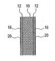
도 1은 본 발명의 원리에 따라 구성되고 작용하는 유연한 반사단열구조의 일면 구조의 개략적 단면도;1 is a schematic cross-sectional view of one side structure of a flexible reflective insulation structure constructed and operative in accordance with the principles of the present invention;
도 2a, 2b는 압축저장상태와 압축되지 않은상태의 도 1의 유연한 반사단열구조의 단면도들;2A and 2B are cross-sectional views of the flexible reflective thermal insulation structure of FIG. 1 in a compressed storage state and an uncompressed state;
도 3은 도 1의 실시예의 이중면 변형례의 단면도;3 is a cross-sectional view of a double-sided variant of the embodiment of FIG. 1;
도 4는 폴리머 보강층을 채택한 도 1의 실시예의 다른 양면 변형례의 단면도;4 is a sectional view of another double sided variant of the embodiment of FIG. 1 employing a polymer reinforcement layer;
도 5는 폴리머 보강반사층을 채택한 도 1의 실시예의 또다른 양면 변형례의 단면도;5 is a cross-sectional view of another two-sided variant of the embodiment of FIG. 1 employing a polymeric reinforcement reflective layer;
도 6은 본 발명에 따른 유연한 반사단열구조를 이용해 공동 벽면을 구성하는 예의 단면도;6 is a cross-sectional view of an example of constructing a cavity wall surface using a flexible reflective insulating structure according to the present invention;
도 7은 본 발명에 따른 유연한 반사단열구조를 이용해 단열성을 향상시킨 예의 단면도;7 is a cross-sectional view of an example of improving the thermal insulation using a flexible reflective insulating structure according to the present invention;
도 8은 직포섬유층을 포함한, 본 발명의 원리에 따라 구성되고 작용하는 유연한 반사단열구조의 폴리머 보강 실시예의 단면도;8 is a cross-sectional view of a polymer reinforced embodiment of a flexible reflective thermal insulation structure constructed and functioned in accordance with the principles of the present invention, including a woven fiber layer;
도 9는 본 발명을 이용한 텐트의 단면도;9 is a cross-sectional view of a tent using the present invention;
본 발명은 건물, 텐트, 기타 용도로 사용되는 유연한 반사단열구조를 제공한다.The present invention provides a flexible reflective insulation structure used for buildings, tents, and other uses.
본 발명에 따른 유연한 반사단열구조의 원리와 작용은 첨부 도면들과 설명에 의해 더 잘 이해될 수 있을 것이다.The principle and operation of the flexible reflective insulation structure according to the present invention will be better understood by the accompanying drawings and the description.
도 1-8에는 유연한 반사단열구조의 각종 적용례와 응용례가 도시되어 있는 바, 이들은 본 발명의 원리에 따라 구성되고 작용한다.1-8 show various applications and applications of the flexible reflective insulation structure, which are constructed and function in accordance with the principles of the present invention.
일반적으로, 본 발명의 유연한 반사단열구조는 하나 이상의 유연한 섬유층(10)과 하나 이상의 유연한 금속층(12)을 포함하고, 이 금속층의 제1 표면(14)의 복사율은 0.1보다 작으며, 바람직하게는 0.05 이하이다. 상기 금속층(12)의 제1 표면(14)의 복사율이 0.1 이상이면 금속층 자체의 단열효과가 크지 않아 후술하는 섬유층(10)과의 결합 효과를 충분히 발휘할 수 없게 된다.
상기 금속층(12)은 제1 표면(14)이 섬유층(10)을 향한채 섬유층(10)에 부착된다. 이 섬유층(10)은 제1 표면(14)의 약 85% 이상의 복사율, 바람직하게는 약 95% 이상의 복사율, 더 바람직하게는 약 97% 이상의 복사율이 실질적으로 변하지 않도록 금속층(12)에 부착되는 것이 바람직하다. 제1 표면(14)의 약 85% 이상이 복사율에 있어서 영향을 받지 않으면 소정의 복사장벽을 형성하는데 지장이 없다. 즉, 금속층(12)의 제1 표면의 복사율의 영향을 받지 않는 부분이 85% 미만에서는, 섬유층과의 접촉면적의 증가에 따라 효과가 향상됨이 없이 오히려 제1 표면의 낮은 복사율에 악영향을 주게 된다.In general, the flexible reflective insulation structure of the present invention comprises at least one
The
낮은 복사율 표면에 인접하여 유연한 섬유재료를 사용하면 종래의 기술에 비해 아주 유리하다는 것이 이해되어져야 한다. 첫째, 섬유재료의 성질은 총 면적이 아주 작은 접촉점이나 접촉라인을 형성하기 쉬우므로, 낮은 복사 특성의 표면과 최소한으로 간섭하면서 반사면의 부착을 용이하게 한다. 이와 동시에, 섬유 재료는 반사층을 갖는 복사장벽을 제공한다는 점에서 정확히 개방 공기층으로 기능함이 발견되었고, 그와 동시에 공기순환을 상당히 방해하여 대류 및 전도에 대해 아주 효과적인 통상의 절연성을 제공한다. 본 발명의 이와 같은 장점들은 다음 설명을 보면 명확해질 것이다.It should be understood that the use of a flexible fiber material adjacent to a low emissivity surface is very advantageous over the prior art. First, the properties of the fiber material tend to form contact points or contact lines with a very small total area, thus facilitating the attachment of reflective surfaces with minimal interference with low radiant surfaces. At the same time, the fiber material has been found to function exactly as an open air layer in that it provides a radiation barrier with a reflective layer, while at the same time significantly hindering the air circulation, providing a very effective conventional insulation against convection and conduction. These advantages of the present invention will become apparent from the following description.
섬유 재료는 본 발명의 범위를 전혀 제한하지 않고 복사방벽내에서 거의 정확히 개방된 공기층으로 행동한다는 놀라운 관찰과 관련하여, 이 관찰은 반사단열재 이론에서 음향기준을 갖는다고 믿어진다. 특히, 열의 흐름방향에 직각인 두개의 표면을 경계로 하는 단일 반사 공기층의 유효 복사율 E는 다음과 같이 주어진다.In connection with the surprising observation that the fiber material behaves almost exactly as an open air layer within the radiation barrier without limiting the scope of the invention at all, it is believed that this observation has an acoustic reference in reflective insulation theory. In particular, the effective emissivity E of a single reflective air layer bordering two surfaces perpendicular to the flow direction of heat is given by

여기서 ε1, ε2는 각각 표면의 복사율이다. 한쪽 표면의 복사율이 낮으면(ε1, =0.039), 다른 표면의 복사율이 흑체에 가깝더라도(ε2=0.9), 시스템 전체의 복사율 E는 낮게 유지된다(E=0.039). 따라서, 접촉면적이 아주 낮게 유지되는한, 복사율이 낮은 표면을 마주보는 공기층내에 섬유들이 존재하면 본 발명에 의해 제공되는 복사방벽의 효과가 손상되지 않는다.Where ε1 and ε2 are the emissivity of the surface, respectively. If the emissivity of one surface is low (ε1 , = 0.039), even if the emissivity of the other surface is close to the black body (ε2 = 0.9), the emissivity E of the entire system remains low (E = 0.039). Thus, as long as the contact area remains very low, the presence of fibers in the air layer facing the low emissivity surface does not impair the effect of the radiation barrier provided by the present invention.
도 1, 2a, 2b에 따르면, 부직포 섬유층(10)을 이용한 본 발명의 원리를 구현하는 첫번째 기본례가 도시되어 있다.1, 2A, 2B, a first basic example of implementing the principles of the present invention using a nonwoven
부직포 재료를 이용하면 많은 특별한 이점이 얻어진다. 가장 현저한 것은, 부직포 재료는 도 2a와 같이 두루마리 형태로 압축된 상태에서는 압축되는 구조로 되고, 도 2b와 같이 펼쳐진 상태에서는 원상태로 복귀되는 구조로 된다는 것이다. 최대 체적 복귀 기간은 1주일까지 갈 수 있다. 복귀되어 압축이 풀린 두께 T2는 압축두께 T1의 두배 이상인 것이 바람직하지만, 5배 이상이 더 좋고, 8배 이상인 것이 가장 좋다. 따라서, 두루마리 형태로 압축된 상태에서는 두께가 2-4㎜인 층은 복구된 뒤에는 10-30㎜ 두께의 섬유층을 제공할 수 있다. 이렇게 되면, 보관과 운송 비용이 대폭 절감된다.Many special advantages are obtained with the use of nonwoven materials. Most notably, the nonwoven material has a structure in which the nonwoven material is compressed in a rolled form as shown in FIG. 2A, and returns to its original state in an unfolded state as shown in FIG. 2B. The maximum volume return period can go up to one week. It is preferable that the thickness T2 returned and decompressed istwo times or more than the compression thickness T1 , but five times or more is better, and eight times or more is best. Thus, in the compressed state in the form of a roll, a layer having a thickness of 2-4 mm may be provided to provide a 10-30 mm thick fibrous layer after recovery. This significantly reduces storage and transportation costs.
전술한 바와 같이, 섬유재료들을 이용하는 가장 큰 장점은 공기대류를 상당히 방해한다는데 있다. 특히, 비교적 직경이 작으면서도 큰 유동완충효과를 갖는 섬유를 이용할 때는 더하다. 반면, 직경이 작은 섬유들은 탄성이 작기 때문에 효과적인 체적복귀가 방해받을 수 있다. 이 문제를 해결하기 위해, 섬유재료들은 직경이 서로 다른 섬유들로 구성되는 것이 바람직하다. 통상, 비교적 직경이 큰 섬유들을 약 20wt%, 직경이 작은 섬유들을 약 80wt%로 하면 효과가 높다는 것이 발견되었다. 소직경 섬유에 대한 대직경 섬유의 직경비는 사용된 재료의 특성에 따라 2:1 이상이고 대개 상당히 더 크다.As mentioned above, the greatest advantage of using fiber materials is that they significantly interfere with air convection. In particular, when using a fiber having a relatively small diameter and a large flow buffering effect. On the other hand, small diameter fibers are less elastic and thus effective volume recovery may be hindered. In order to solve this problem, the fiber materials are preferably composed of fibers of different diameters. In general, it has been found that the effect is high when the relatively large diameter fibers are about 20 wt% and the small diameter fibers are about 80 wt%. The diameter ratio of large diameter fibers to small diameter fibers is at least 2: 1 and usually considerably larger, depending on the properties of the materials used.
제1 표면(14)에 먼지가 붙는 것을 피하려면, 섬유층(10)이 보통 사용조건에서 상당히 방진특성을 갖도록 하는 것이 바람직하다. 이를 위해, 많은 섬유들을 절단하여 상당한 먼지를 발생시키지 않도록, 구부러지고, 접혀지고, 찢겨지고 거칠게 처리될 수 있는 유연한 섬유재료를 사용하는 것이 바람직하다. 이러한 이유로, 직물공업에서 공통적으로 사용되는 유연한 섬유들이 통상의 단열재 분야에서 주로 사용되는 부서지기 쉬운 섬유(birttle fiber)보다 일반적으로 더 바람직하다. 바람직한 재료로는, 폴리에스테르 섬유, 직조 폴리아미드 섬유(나일론), 주름잡힌 아크릴섬유가 있지만 이에 한정되지는 않는다. 가장 바람직한 실시예에서, 섬유층(10)은 주로 폴리에스테르 섬유로 구성되지만, 더 바람직한 것은 저융점 폴리에스테르 섬유와 중공(hollow) 폴리에스테르 섬유를 혼합한 것이다.To avoid dust adhering to the
접촉면적이 적으면서 반사단열재에 유효한 공기층을 제공하기 위해, 본 발명의 대부분의 경우 섬유층의 구조는 압축되지 않은 상태에서 두께 10 ㎝당 약 4 ㎏/㎡의 밀도를 넘지 않는 "통풍" 구조가 바람직하다. 바람직한 경우로서, 두께 10 ㎝당 밀도가 약 0.4-2 ㎏/㎡를 넘지 않는 저밀도 부직포 재료를 사용한다. 여기서, 하한치인 0.4는 자체 구조를 형성할 수 있는 최소값이다.In order to provide an effective air layer for the reflective insulating material while having a small contact area, in most cases of the present invention, the structure of the fibrous layer is preferably a "ventilating" structure which does not exceed a density of about 4 kg / m 2 per 10 cm of thickness in the uncompressed state. Do. As a preferred case, a low density nonwoven material is used whose density per 10 cm of thickness does not exceed about 0.4-2 kg / m 2. Here, the lower limit of 0.4 is the minimum value capable of forming its own structure.
선택적으로, 금속층(12)에 인접한 섬유층(10)(바람직하게는 두께가 2-4 ㎜)이 대부분의 섬유재료에 비해 작은 섬유밀도를 나타내도록, 섬유층(10)이 처리될 수도 있다. 이 표면층의 특성은 두께 10 ㎝당 밀도가 약 0.3-1.0 ㎏/㎡에 상당하도록 하는 것이 바람직하다. 이와 같은 공정은, 표면결합공정이나 초기의 두툼한 블록에서 재료층을 제거하는 등의 기존의 공정에 의해 달성될 수 있다. 그러나, 이런 추가적인 표면-박막화 기술들은, 전술한 바와 같이, 인접표면에 대한 통기성 섬유재료의 표면접촉면적이 본래 아주 낮기 때문에 종종 불필요하다는 것을 주목해야 한다.Optionally, the
이렇게 낮은 밀도에서 요구되는 전체적 및 구조적인 무결성을 확보하려면, 섬유층(10)내의 섬유 형성에 관련해 예방조치가 이루어져야 한다. 먼저, 섬유층(10)내의 섬유로는 권축섬유(crimped fiber), 바람직하게는 이중권축섬유를 사용해, 이 섬유들이 평탄부를 나타내지 않도록 휘어지게 한다. "권축"이란 섬유를 꼬불꼬불하게 처리하는 것을 말한다. 이렇게 하면 비교적 낮은 섬유밀도에서도 기계적 지지성이 좋아진다. 또, 층들사이가 서로 연결이 잘 되기에 충분히 변형된 일차 연신방향을 갖는 섬유를 생산하도록 제조공정을 구성하는 것이 바람직하다.In order to ensure the overall and structural integrity required at such low densities, precautions should be taken with regard to fiber formation in the
저밀도에 대한 일반적인 선호에 대한 예외가 텐트 등에 사용하는 얇은 섬유층들의 경우에 있으며, 충분한 구조적 무결성을 제공하려면 비교적 고밀도가 바람직하다. 특히, 이런 구조물들은 비교적 낮은 압축성을 가지는 2-5㎜의 부직포나 직조 재료의 고밀도 층들을 이용한다.An exception to the general preference for low density is in the case of thin fiber layers used in tents and the like, and relatively high density is desirable to provide sufficient structural integrity. In particular, these structures utilize high density layers of 2-5 mm nonwoven or woven material with relatively low compressibility.
금속층(12)은 금속 호일 시트로 가장 간단히 구현할 수 있다. 한편, 금속층(12)에 인접하게 기판을 제공할 경우, 금속층(12)을 기판 표면에 증착할 수도 있다(도 4, 5 참조). 일반적으로 알루미늄을 많이 사용하지만, 부식이 잘 안되고 복사율이 낮은 다른 금속들로 대체할 수도 있다. 예를 들면, 황동, 동, 금, 은, 백금 등이 있지만, 이에 한정되지는 않는다. 복사율이 낮은 표면은 연마하는 것이 바람직하다. 한편, 금속호일 시트의 외측면의 복사특성이 낮도록 처리할 수도 있다. 그러나, 본 발명에 따른 일차 작동 (저복사율) 반사면의 제1 표면(14)이 전술한 열화 문제로부터 보호되어야 한다.The
금속층(12)은 여러 기술중 하나에 의한 접착에 의해 섬유층(10)에 부착되는 것이 바람직하다. 가장 바람직한 기술에 의하면, 섬유층(10)에 대해 간격을 둔 무부하 롤러를 이용해 섬유층에서 돌출한 섬유들만이 금속층(12)에 충분히 접촉되도록 섬유재료에 접착제를 도포한다. 다음 금속층을 접착제를 도포한 섬유에 접촉시킨다. 사용된 접착제는 금속층과의 접촉부를 따라 큰 방울들이 번지는 것을 피하도록 저밀도인 것이 바람직하다. 한편, 금속층을 저융점 섬유와 접촉시키되, 상기 저융점 섬유를 융점까지 가열하여 약간 눌러서, 금속층에 번져 낮은 복사율을 해치는 큰 방울들의 형성을 방지할 수도 있다.The
다른 접착기술로는 두개 층을 서로 접착하기 전에 금속층이나 섬유층의 작은 표면적을 가로질러 접착제 패턴을 형성하는 방법이 있다. 총면적의 40% 미만, 바람직하게는 5% 미만, 더 바람직하게는 3% 미만에 해당하는 면적의 사각형, 육각형 또는 작은 점들의 격자형 패턴이 적절하다.Another bonding technique is to form an adhesive pattern across a small surface area of a metal or fibrous layer before bonding the two layers together. A lattice pattern of squares, hexagons or small dots of an area corresponding to less than 40%, preferably less than 5%, more preferably less than 3% of the total area is suitable.
적당한 접착제로는 다양한 고온 아교, 공기건조 아교, 열작용 접착제들이 있지만 이에 한정되지는 않는다.Suitable adhesives include, but are not limited to, a variety of hot glue, air dry glue, thermal adhesives.
또다른 접착기술로는 섬유층 재료가 제1 표면(14)의 약 15% 미만, 바람직하게는 5% 미만, 더 바람직하게는 3% 미만만 접촉하도록 섬유층의 섬유들을 최소 압력으로 국부적으로 웰딩하는 방법이 있다.Another bonding technique is a method of locally welding the fibers of a fiber layer to a minimum pressure such that the fiber layer material contacts only less than about 15%, preferably less than 5%, more preferably less than 3% of the
본 발명의 다양한 다른 예들중에서도 바람직한 특성으로는, 섬유층(10)의 양면을 감싸는 것이 있다. 이렇게 하면 구조물의 대류단열특성이 향상됨은 물론 저복사율 표면을 통해 먼지나 분진이 침투하지 않는 거의 밀폐된 유니트를 형성하게 된다. 밀봉성을 더 향상시키기 위해, 제조중에나 설치중에 플라스틱 박막으로 구조물 가장자리를 둘러쌀 수도 있다.Among the various other examples of the present invention, a desirable feature is to surround both sides of the
추가 금속층을 이용해 밀봉을 하여 먼지나 공기 유입을 차단하는 외에, 이중 복사방지기능을 구조물에 형성하여, 단열성을 더 향상시킬 수 있다. 이런 구조의 예가 도 3에 도시되어 있는바, 그 경계면은 도 1에서 설명한 것과 완전히 동일하다.In addition to sealing with an additional metal layer to block dust and air ingress, double radiation protection can be formed on the structure to further improve thermal insulation. An example of such a structure is shown in FIG. 3, the interface of which is exactly the same as that described in FIG.
도 4의 변형례에서, 단열구조물은 금속층(12)의 외측면에 부착된 기판층(16)을 더 포함한다. 이 경우, 전술한 바와 같이, 금속층은 기판층에 접착된 호일층이거나 기판층에 증착된 코팅일 수 있다. 사용하고자 하는 경우에 따라, 원하는 정도의 기계적강도, 내마모성, 방수성 또는 기타 물리기계적 특성을 제공하도록 기판층(16)을 선택할 수 있다. 적당한 기판층으로는 직물, 종이, 및 폴리에틸렌, PVC, 나일론, 폴리에스테르를 포함한 여러 폴리머가 있지만, 반드시 이에 한정되지는 않는다. 어떤 경우에는, 직물기판과 기타 찢어지지 않는 폴리머기판을 사용하고 이 구조물을 재봉질 할 수 있기 때문에 특히 유리할 수도 있다. 이 경우, 구조물의 여러 층들을 서로 연결하는 일차 모드가 재봉질일 수 있다. 실의 위치로 인해 단열성이 손상되지 않도록 재봉질된 부분에 밀봉제를 바르는 것이 바람직하다. 또, 한편으로는, 재봉질로 생긴 구멍을 밀봉하도록 습기에 노출되면 팽창되는 실을 사용 할 수도 있다. 다목적 텐트와 같이 어떤 날씨에도 사용하려면, 자외선과 날씨에 견디는 첨가제를 갖는 소성 PVC를 선택하는 것이 가장 바람직하다.In the variant of FIG. 4, the thermal insulation structure further comprises a
본 발명에 따른 단열구조를 적용해 적어도 한쪽 벽을 구성한 텐트가 도 9에 간단히 예를 들어 도시되어 있다. 여기서, "텐트"란 지지구조에 의해 지지되거나 공기로 지지되는 유연한 재료로 구성된 모든 구조물을 의미한다. 이런 경우의 폴리머 재료는 강도를 유지하기 위해 그 두께가 약 50㎛ 이상, 바람직하게는 약 500㎛ 이상이고, 재료의 내후성을 향상시키도록 선택된 하나 이상의 첨가제를 함유하는 것이 바람직하다.A tent consisting of at least one wall by applying the thermal insulation structure according to the invention is shown by way of example in FIG. 9. Here, "tent" means any structure made of a flexible material supported by a support structure or supported by air. The polymer material in this case preferably has a thickness of at least about 50 μm, preferably at least about 500 μm, and contains at least one additive selected to improve the weather resistance of the material in order to maintain strength.
구조적 강도 향상을 위해, 기판층(16)의 폴리머에 다수의 보강요소들(18)을 삽입할 수 있다. 이들 보강요소들은 인장강도를 향상시키기 위해 선택한다. 적당한 보강요소로는 기다란 섬유재, 직포, 부직포가 있지만, 반드시 이에 한정되는 것은 아니다.In order to improve the structural strength, a plurality of reinforcing
도 5도의 변형례에는 기판층(16) 뒷면에 제2 금속층(20)이 접착되거나 증착되어 있다. 이렇게 하면 두개의 저복사면을 갖는 호일시트와 같은 복사특성을 갖는 보강된 샌드위치 구조가 형성된다. 전술한 바와 같이, 섬유층(10)을 향한 표면에 의해 본 발명의 주요 반사장벽들이 제공되지만, 많은 경우 반사단열성을 더 향상시키도록 제2 금속층(20)을 외측면에 배치할 수도 있다.In the modification of FIG. 5, the
도 6, 7에는 본 발명의 응용례가 도시되어 있다. 도 6의 공동벽(22)에는 도 3, 5의 단열구조물이 삽입된다. 이 구조물은 다수의 스페이서 요소들(24)에 의해 내벽면에서 약간 떨어져 장착된다. 이렇게 생긴 공기층에 의해 열전도에 대한 추가 방벽이 생기고, 도 5의 구조물의 경우에는 추가 복사방벽이 생긴다. 반대쪽에는 전 기케이블(26) 등을 배치하기 위한 큰 간격이 필요할 수도 있다. 그러나, 본 발명에 의하면 필요에 따라 하나의 두툼한 섬유층(10)을 이용하거나 이들 층 구조물 전체나 일부를 반복 배치하여 어떤 두께의 공동도 쉽게 구성할 수 있음을 알아야 한다.6 and 7 show application examples of the present invention. The heat insulation structure of FIGS. 3 and 5 is inserted into the
도 7에는 콘크리트나 회반죽 천정(28)의 위에 단열성을 향상시키기 위해 본 발명을 적용한 경우가 도시되어 있다. 여기서는 두개의 섬유층(10)을 각각의 금속층(12) 위에 겹쳐서 다층구조로 본 발명을 구성하였다. 적어도 중간 금속층(12)은 도 5와 같은 샌드위치 구조로 구현하여, 상향 복사방벽을 추가로 형성하는 것이 바람직하다. 한편, 하부 섬유층(10) 밑에 폴리머층(30)을 더 배치하여 단열구조 바닥을 밀봉할 수도 있다.7 shows a case where the present invention is applied to improve the thermal insulation on the concrete or plaster ceiling (28). Here, the present invention is constructed in a multi-layered structure in which two
본 발명의 실시예에서는 이 구조물을 설치하기 전에 공급 및 운반하기 쉽도록 상당한 유연성을 갖는다. 따라서, 도 7의 경우, 이 구조물은 섬유층이 양면에 부착되어 있는 반사시트(또는 샌드위치)로서 공급될 수 있다. 최상부 금속층은 설치중에 부착해도 된다. 한편, 도 5에서 설명한 바와 같이 별도로 배치된 섬유층(10)에 부착되거나 간단히 덧댈 수 있는 유니트로서 상부층들을 공급할 수도 있다. 또 다른 한편으로는, 도 1에서 설명한 구조물들(도 7의 하부)과 도 3에서 설명한 구조물들을 결합하여 형성할 수도 있다.Embodiments of the present invention have considerable flexibility to facilitate supply and transport prior to installing this structure. Thus, in the case of FIG. 7, this structure can be supplied as a reflective sheet (or sandwich) with a fibrous layer attached to both sides. The uppermost metal layer may be attached during installation. Meanwhile, as described in FIG. 5, the upper layers may be supplied as a unit that can be attached or simply added to the separately disposed
도 8에 도시된 바와 같이, 직포 섬유층(32)을 이용해 본 발명을 구현할 수도 있다. 이런 경우에는 통상 두께 2.5㎜ 이하의 직포재료가 경제성이 있다고 믿어진다. 폴리머 받침(36) 등을 이용해 이 재료를 강화할 수도 있다.As shown in FIG. 8, the woven
많은 경우, 직포 재료의 본체에서 충분한 크기의 섬유들이 돌출하면 더이상 의 준비 없이도 금속층을 좁은 접촉면적에서 부착할 수 있다. 그러나, 다른 경우에는, "기모(raising)"로 알려진 기술로 재료를 처리하여 직포 재료에서 다수의 기모섬유들(34)을 외측으로 돌출시켜 금속층(12)을 지지하는 것이 바람직할 수 있다.In many cases, when the fibers of sufficient size protrude from the body of the woven material, the metal layer can be attached at a narrow contact area without further preparation. In other cases, however, it may be desirable to process the material with a technique known as " raising " to support the
본 발명의 부직포 적용례보다 덜 압축되겠지만, 기모섬유들(34)도 상당한 정도의 탄성압축성을 가지므로 두께가 약 2배 정도 감축될 수 있다.Although less compressed than the nonwoven application of the present invention, the brushed
이상 바람직한 실시예들에 대해 본 발명을 설명하였지만, 본 발명은 이에 한정되지 않으며 본 발명의 범위내에서 다양한 다른 변형이 가능하다는 것을 알아야 한다.While the invention has been described above with respect to preferred embodiments, it should be understood that the invention is not limited thereto and that various other modifications are possible within the scope of the invention.
Claims (27)
Translated fromKoreanApplications Claiming Priority (2)
| Application Number | Priority Date | Filing Date | Title |
|---|---|---|---|
| US09/501,592US6599850B1 (en) | 2000-02-10 | 2000-02-10 | Flexible reflective insulating structures |
| US09/501,592 | 2000-02-10 |
Publications (2)
| Publication Number | Publication Date |
|---|---|
| KR20020089346A KR20020089346A (en) | 2002-11-29 |
| KR100668178B1true KR100668178B1 (en) | 2007-01-11 |
Family
ID=23994193
Family Applications (1)
| Application Number | Title | Priority Date | Filing Date |
|---|---|---|---|
| KR1020027010393AExpired - Fee RelatedKR100668178B1 (en) | 2000-02-10 | 2001-02-09 | Flexible reflective insulation structure |
Country Status (14)
| Country | Link |
|---|---|
| US (2) | US6599850B1 (en) |
| EP (1) | EP1268194B1 (en) |
| JP (1) | JP5127015B2 (en) |
| KR (1) | KR100668178B1 (en) |
| CN (1) | CN1261297C (en) |
| AT (1) | ATE284785T1 (en) |
| AU (2) | AU2001236788B2 (en) |
| CA (1) | CA2399614C (en) |
| DE (1) | DE60107822T2 (en) |
| ES (1) | ES2234814T3 (en) |
| IL (1) | IL151107A0 (en) |
| PT (1) | PT1268194E (en) |
| WO (1) | WO2001058683A1 (en) |
| ZA (1) | ZA200206398B (en) |
Families Citing this family (51)
| Publication number | Priority date | Publication date | Assignee | Title |
|---|---|---|---|---|
| US6599850B1 (en)* | 2000-02-10 | 2003-07-29 | Raphael Heifetz | Flexible reflective insulating structures |
| US20070155265A1 (en)* | 2000-06-19 | 2007-07-05 | Anderson Jerry C | Aircraft insulation |
| US7166547B2 (en)* | 2000-06-30 | 2007-01-23 | Owens Corning Fiberglas Technology, Inc. | Under carpet heat shield and floor pan insulator |
| US20050118915A1 (en)* | 2001-02-09 | 2005-06-02 | Raphael Heifetz | Flexible reflective insulating structures |
| JP2004528222A (en) | 2001-06-01 | 2004-09-16 | オウェンス コーニング | Bonnet liner, dashboard liner, firewall liner or engine cover liner |
| WO2003038503A1 (en)* | 2001-11-02 | 2003-05-08 | Olympus Corporation | Scanning con-focal microscope |
| US6869661B1 (en)* | 2002-10-24 | 2005-03-22 | David D. Ahr | Flexible radiant barrier |
| KR100506127B1 (en)* | 2002-10-28 | 2005-08-17 | 이경인 | Insulation Windows Using Film |
| GB2405415A (en)* | 2003-08-29 | 2005-03-02 | Knauf Insulation Ltd | Encapsulated insulation with metallised polyethylene film having low emissivity |
| US20050098255A1 (en)* | 2003-11-06 | 2005-05-12 | Lembo Michael J. | Insulation product having nonwoven facing and process for making same |
| US20050138834A1 (en)* | 2003-12-03 | 2005-06-30 | Suda David I. | Fiberglass insulation curing oven tower and method of curing fiberglass insulation |
| US7252868B2 (en)* | 2004-01-08 | 2007-08-07 | Certainteed Corporation | Reinforced fibrous insulation product and method of reinforcing same |
| US20050095419A1 (en)* | 2004-07-01 | 2005-05-05 | Raeburn Stephen W. | Reinforced adhered insulation material, and methods of use and making thereof |
| US20060078699A1 (en)* | 2004-10-12 | 2006-04-13 | Mankell Kurt O | Insulation board with weather and puncture resistant facing and method of manufacturing the same |
| GB0423523D0 (en)* | 2004-10-22 | 2004-11-24 | Hunt Tech Ltd | Multi-layer vapour permeable thermal insulation system |
| FR2884589B1 (en)* | 2005-04-15 | 2007-06-08 | Icopal Sas Soc Par Actions Sim | REFLECTIVE THIN INSULATION FOR UNDERROOF, AND METHOD OF MANUFACTURING THE INSULATION |
| FR2885987A1 (en)* | 2005-05-20 | 2006-11-24 | Velysam Sarl | Multilayer reflective insulating material for e.g. house construction, has fibers covering partially metallized reflective film, and multilayer assembly constituted of batting film on metallized framed sealed film and polyethylene foam |
| GB0605747D0 (en)* | 2006-03-22 | 2006-05-03 | Hunt Tech Ltd | Improvements in or relating to thermal insulation systems |
| US7935410B2 (en) | 2006-04-19 | 2011-05-03 | Furio Orologio | Metallized polymeric film reflective insulation material |
| US7935411B2 (en) | 2006-04-19 | 2011-05-03 | Furio Orologio | Metallized polymeric film reflective insulation material |
| FR2902123B1 (en)* | 2006-06-08 | 2008-07-18 | Loda Sarl | SCREEN OF UNDERROOF |
| FR2922913A1 (en)* | 2007-10-31 | 2009-05-01 | Soprema Soc Par Actions Simpli | Flexible composite material for thermal and/or phonic insulation of roofer of building, has structure with sheet components, and foil layer forming surface of one sheet component oriented towards exterior with respect to space |
| FR2931493A1 (en)* | 2008-05-20 | 2009-11-27 | Johan Geusens | Insulation sandwich structure for construction of building, has two sets of parallel air films found between corresponding panels and aluminum sheets, where one set of air films is ventilated and another set of air films is not-ventilated |
| KR101353889B1 (en)* | 2008-05-22 | 2014-01-20 | 코오롱인더스트리 주식회사 | Reflection member |
| US8056953B2 (en)* | 2008-06-13 | 2011-11-15 | Itt Manufacturing Enterprises, Inc. | Thermal barrier system |
| US20100282356A1 (en)* | 2009-05-07 | 2010-11-11 | Scott Sawyer | Low emissive radiant barrier flex (LOW-E FLEX) |
| CN101949196B (en)* | 2010-09-17 | 2012-05-30 | 天津科技大学 | Inflatable wall material and inflatable micro refrigeration house adopting same |
| US8997767B2 (en)* | 2011-10-28 | 2015-04-07 | Richard W. Hotes | Multi-layer shelter insulation system |
| US11058161B2 (en) | 2012-02-16 | 2021-07-13 | Xefco Pty Ltd | Heat reflecting composites with knitted insulation |
| US9340994B2 (en) | 2012-08-28 | 2016-05-17 | Alaska Structures, Inc. | Portable shelter with outer vinyl and low emissivity layers |
| US9719206B2 (en) | 2012-09-14 | 2017-08-01 | Under Armour, Inc. | Apparel with heat retention layer and method of making the same |
| USD765427S1 (en) | 2013-03-11 | 2016-09-06 | Under Armour, Inc. | Upper body garment with areas of interior surface ornamentation |
| USD766599S1 (en) | 2013-03-11 | 2016-09-20 | Under Armour, Inc. | Lower body garment with inner surface ornamentation |
| USD758745S1 (en) | 2013-03-11 | 2016-06-14 | Under Armour, Inc. | Lower body garment with outer surface ornamentation |
| US10160184B2 (en)* | 2013-06-03 | 2018-12-25 | Xefco Pty Ltd | Insulated radiant barriers in apparel |
| CN104175649A (en)* | 2013-12-19 | 2014-12-03 | 南宁市磁汇科技有限公司 | Fire retardant blanket |
| US10492550B2 (en) | 2014-01-28 | 2019-12-03 | Under Armour, Inc. | Article of apparel including thermoregulatory textile |
| MX2017002545A (en)* | 2014-08-29 | 2017-05-25 | Owens Corning Intellectual Capital Llc | Duct liner. |
| JP6518557B2 (en)* | 2015-08-31 | 2019-05-22 | 住友理工株式会社 | Thermal insulation cloth |
| US9845596B2 (en) | 2015-09-29 | 2017-12-19 | Awi Licensing Llc | Ceiling system |
| EP3358976B1 (en) | 2015-10-05 | 2022-03-02 | Nike Innovate C.V. | Thermally-insulated garment |
| US20180313080A1 (en)* | 2015-10-23 | 2018-11-01 | Schmetzer Industries Holdings Pty Ltd | Insulation Material Arrangement And Method For Forming An Insulation Material |
| JPWO2018074603A1 (en)* | 2016-10-20 | 2019-08-29 | ちきゅうにやさしい株式会社 | Heat shield structure and method of adding a heat shield structure |
| US11319138B2 (en)* | 2018-11-20 | 2022-05-03 | Simple Container Solutions, Inc. | Pop-up liner |
| CN110001160A (en)* | 2019-04-02 | 2019-07-12 | 中国兵器工业第五九研究所 | A kind of multi-layered composite heat-insulating component resistant to high temperature and preparation method thereof |
| US12076959B2 (en) | 2019-06-28 | 2024-09-03 | Xefco Pty Ltd | Substrate with deposition and/or friction reduction coating |
| CA3122604A1 (en)* | 2020-06-18 | 2021-12-18 | Cascades Canada Ulc | Thermal liner and thermal container comprising same |
| WO2022125430A1 (en)* | 2020-12-10 | 2022-06-16 | Soft-Tex International, Inc. | Warming cushions, blankets and clothing and related methods |
| CA3204276A1 (en) | 2021-01-08 | 2022-07-14 | Stephen D. Miller | High temperature flexible insulation for extreme environments |
| US12157294B2 (en)* | 2021-07-23 | 2024-12-03 | Whirlpool Corporation | Scrim layer on insulation |
| CA3158774A1 (en)* | 2022-05-13 | 2023-11-13 | Gnb Global Inc. | Insulated tensioned sheet wall system for a building |
Family Cites Families (33)
| Publication number | Priority date | Publication date | Assignee | Title |
|---|---|---|---|---|
| JPS4311505Y1 (en)* | 1965-11-25 | 1968-05-18 | ||
| US3772137A (en)* | 1968-09-30 | 1973-11-13 | Du Pont | Polyester pillow batt |
| US3616139A (en) | 1969-01-21 | 1971-10-26 | Peter Jones | Multilayered thermal insulators |
| US4102352A (en)* | 1976-03-25 | 1978-07-25 | Kirkham Arthur J | Insulated tent |
| JPS58652Y2 (en)* | 1977-11-16 | 1983-01-07 | 積水化成品工業株式会社 | cold weather clothing |
| US4247599A (en) | 1978-12-26 | 1981-01-27 | Insulating Shade | Composite sheet material having low emittance characteristics |
| US4430286A (en)* | 1980-07-14 | 1984-02-07 | Celotex Corporation | Variable density board having improved thermal and acoustical properties and method and apparatus for producing same |
| JPS57138642U (en)* | 1981-02-24 | 1982-08-30 | ||
| JPS5896933U (en)* | 1981-12-22 | 1983-07-01 | ユニチカ株式会社 | insulation sheet |
| US4395455A (en)* | 1982-01-28 | 1983-07-26 | E. I. Du Pont De Nemours And Company | Polyester fiberfill batting having improved thermal insulating properties |
| JPS5964235U (en)* | 1982-10-20 | 1984-04-27 | 旭化成株式会社 | fiber laminate |
| JPS59199856A (en)* | 1983-04-25 | 1984-11-13 | 東レ株式会社 | Nonwoven sheet and production thereof |
| US4531511A (en) | 1983-07-14 | 1985-07-30 | Hochberg Nelson D | Means for controlling heat flux |
| US4637947A (en)* | 1984-08-14 | 1987-01-20 | Anmin Manufacturing Co., Ltd. | Heat insulation material |
| US4656082A (en)* | 1984-09-05 | 1987-04-07 | Aci Australia Limited | Laminate material with fibrous inner layer |
| US4622253A (en)* | 1984-10-12 | 1986-11-11 | Harry Levy | Thermal laminated lining and method of manufacture |
| US4733413A (en)* | 1987-03-05 | 1988-03-29 | Shelby Group International, Inc. | Glove construction and method of making |
| US4777086A (en)* | 1987-10-26 | 1988-10-11 | Owens-Corning Fiberglas Corporation | Low density insulation product |
| US4879168A (en)* | 1987-10-28 | 1989-11-07 | The Dow Chemical Company | Flame retarding and fire blocking fiber blends |
| US5230941A (en) | 1988-11-02 | 1993-07-27 | Transtech Service Network, Inc. | Insulative material with reflective space |
| GB8903641D0 (en)* | 1989-02-17 | 1989-04-05 | Courtaulds Plc | Flexible fabric thermal insulators |
| DE69033934T2 (en)* | 1989-05-30 | 2002-11-28 | Atd Corp., Norcross | HEAT-INSULATING LAMINATE |
| GB9020428D0 (en)* | 1990-09-19 | 1990-10-31 | Gore W L & Ass Uk | Thermal control materials |
| JPH0740487A (en)* | 1993-07-26 | 1995-02-10 | Kuraray Co Ltd | Nonwoven structure |
| JPH07280170A (en)* | 1994-04-12 | 1995-10-27 | Kubota Corp | Filling structure of filling material for vacuum insulation |
| JPH08187805A (en)* | 1995-01-13 | 1996-07-23 | Kanebo Ltd | Sound insulation structure |
| US5549956A (en) | 1995-04-06 | 1996-08-27 | Handwerker; Gary | Heat reflective blanket |
| US5767024A (en)* | 1996-04-03 | 1998-06-16 | Atd Corporation | Combined thermal and acoustic insulator |
| CA2211549C (en)* | 1996-09-04 | 2005-06-21 | Krona Industries Ltd. | Low emissivity, high reflectivity insulation |
| JP3188650B2 (en)* | 1997-05-14 | 2001-07-16 | グンゼ株式会社 | Trousers |
| JPH11117162A (en)* | 1997-10-14 | 1999-04-27 | Kam:Kk | Insulation member |
| JPH11343679A (en)* | 1998-04-01 | 1999-12-14 | Nippon Petrochem Co Ltd | Insulation material and its use |
| US6599850B1 (en)* | 2000-02-10 | 2003-07-29 | Raphael Heifetz | Flexible reflective insulating structures |
- 2000
- 2000-02-10USUS09/501,592patent/US6599850B1/ennot_activeExpired - Lifetime
- 2001
- 2001-02-09ESES01908990Tpatent/ES2234814T3/ennot_activeExpired - Lifetime
- 2001-02-09EPEP01908990Apatent/EP1268194B1/ennot_activeExpired - Lifetime
- 2001-02-09CNCNB018048420Apatent/CN1261297C/ennot_activeExpired - Fee Related
- 2001-02-09ILIL15110701Apatent/IL151107A0/enactiveIP Right Revival
- 2001-02-09CACA002399614Apatent/CA2399614C/ennot_activeExpired - Fee Related
- 2001-02-09JPJP2001558256Apatent/JP5127015B2/ennot_activeExpired - Fee Related
- 2001-02-09WOPCT/US2001/004116patent/WO2001058683A1/enactiveIP Right Grant
- 2001-02-09PTPT01908990Tpatent/PT1268194E/enunknown
- 2001-02-09ATAT01908990Tpatent/ATE284785T1/enactive
- 2001-02-09DEDE60107822Tpatent/DE60107822T2/ennot_activeExpired - Lifetime
- 2001-02-09AUAU2001236788Apatent/AU2001236788B2/ennot_activeCeased
- 2001-02-09AUAU3678801Apatent/AU3678801A/enactivePending
- 2001-02-09USUS10/470,332patent/US20040058608A1/ennot_activeAbandoned
- 2001-02-09KRKR1020027010393Apatent/KR100668178B1/ennot_activeExpired - Fee Related
- 2002
- 2002-08-12ZAZA200206398Apatent/ZA200206398B/enunknown
Also Published As
| Publication number | Publication date |
|---|---|
| ZA200206398B (en) | 2003-08-12 |
| JP2003525772A (en) | 2003-09-02 |
| ATE284785T1 (en) | 2005-01-15 |
| KR20020089346A (en) | 2002-11-29 |
| CA2399614C (en) | 2009-06-02 |
| WO2001058683A9 (en) | 2002-10-24 |
| EP1268194A4 (en) | 2003-05-02 |
| DE60107822T2 (en) | 2005-12-01 |
| CN1261297C (en) | 2006-06-28 |
| CA2399614A1 (en) | 2001-08-16 |
| US20040058608A1 (en) | 2004-03-25 |
| DE60107822D1 (en) | 2005-01-20 |
| EP1268194B1 (en) | 2004-12-15 |
| PT1268194E (en) | 2005-04-29 |
| AU2001236788B2 (en) | 2005-09-15 |
| CN1416392A (en) | 2003-05-07 |
| EP1268194A1 (en) | 2003-01-02 |
| US6599850B1 (en) | 2003-07-29 |
| AU3678801A (en) | 2001-08-20 |
| WO2001058683A1 (en) | 2001-08-16 |
| ES2234814T3 (en) | 2005-07-01 |
| JP5127015B2 (en) | 2013-01-23 |
| IL151107A0 (en) | 2003-04-10 |
Similar Documents
| Publication | Publication Date | Title |
|---|---|---|
| KR100668178B1 (en) | Flexible reflective insulation structure | |
| AU2001236788A1 (en) | Flexible reflective insulating structures | |
| CA1308344C (en) | Gypsum backer board | |
| CA2530192A1 (en) | Multi-layer covering | |
| KR101852731B1 (en) | Non-inflammably Highly Efficient Heat Insulator and Method for Preparing the Same | |
| US20050118915A1 (en) | Flexible reflective insulating structures | |
| CA2553359A1 (en) | Composite material | |
| DE60304729D1 (en) | FIRE PROTECTION SCREENS AND ITS MANUFACTURING PROCESS | |
| JP2921366B2 (en) | Metal composite roofing material and its construction method | |
| JP4180435B2 (en) | Roofing material | |
| CN210390350U (en) | Composite heat-insulating fireproof material | |
| JP2007315051A (en) | Sheathing structure | |
| JP4090368B2 (en) | Roofing material | |
| JP4090363B2 (en) | Roofing material | |
| JP4090364B2 (en) | Roofing material | |
| KR200346602Y1 (en) | Pressure-Resistant Hose having prevention pad | |
| JP4090367B2 (en) | Roofing material | |
| JP4180436B2 (en) | Roofing material | |
| JPH0519626B2 (en) | ||
| WO2023170612A1 (en) | Pliable insulation sheet | |
| JPH11247341A (en) | Formwork and thermal insulation | |
| AU642742C (en) | Improvements in reflective foil insulation | |
| AU642742B2 (en) | Improvements in reflective foil insulation | |
| JP2007154590A (en) | External facing material | |
| JPH0526392A (en) | Heat insulating material of pipeline for air-conditioning |
Legal Events
| Date | Code | Title | Description |
|---|---|---|---|
| PA0105 | International application | St.27 status event code:A-0-1-A10-A15-nap-PA0105 | |
| T11-X000 | Administrative time limit extension requested | St.27 status event code:U-3-3-T10-T11-oth-X000 | |
| P11-X000 | Amendment of application requested | St.27 status event code:A-2-2-P10-P11-nap-X000 | |
| P13-X000 | Application amended | St.27 status event code:A-2-2-P10-P13-nap-X000 | |
| T11-X000 | Administrative time limit extension requested | St.27 status event code:U-3-3-T10-T11-oth-X000 | |
| PG1501 | Laying open of application | St.27 status event code:A-1-1-Q10-Q12-nap-PG1501 | |
| T12-X000 | Administrative time limit extension not granted | St.27 status event code:U-3-3-T10-T12-oth-X000 | |
| R17-X000 | Change to representative recorded | St.27 status event code:A-3-3-R10-R17-oth-X000 | |
| R17-X000 | Change to representative recorded | St.27 status event code:A-3-3-R10-R17-oth-X000 | |
| A201 | Request for examination | ||
| P11-X000 | Amendment of application requested | St.27 status event code:A-2-2-P10-P11-nap-X000 | |
| P13-X000 | Application amended | St.27 status event code:A-2-2-P10-P13-nap-X000 | |
| PA0201 | Request for examination | St.27 status event code:A-1-2-D10-D11-exm-PA0201 | |
| E902 | Notification of reason for refusal | ||
| PE0902 | Notice of grounds for rejection | St.27 status event code:A-1-2-D10-D21-exm-PE0902 | |
| T11-X000 | Administrative time limit extension requested | St.27 status event code:U-3-3-T10-T11-oth-X000 | |
| E13-X000 | Pre-grant limitation requested | St.27 status event code:A-2-3-E10-E13-lim-X000 | |
| P11-X000 | Amendment of application requested | St.27 status event code:A-2-2-P10-P11-nap-X000 | |
| P13-X000 | Application amended | St.27 status event code:A-2-2-P10-P13-nap-X000 | |
| E701 | Decision to grant or registration of patent right | ||
| PE0701 | Decision of registration | St.27 status event code:A-1-2-D10-D22-exm-PE0701 | |
| PR1002 | Payment of registration fee | St.27 status event code:A-2-2-U10-U12-oth-PR1002 Fee payment year number:1 | |
| GRNT | Written decision to grant | ||
| PR0701 | Registration of establishment | St.27 status event code:A-2-4-F10-F11-exm-PR0701 | |
| PG1601 | Publication of registration | St.27 status event code:A-4-4-Q10-Q13-nap-PG1601 | |
| PR1001 | Payment of annual fee | St.27 status event code:A-4-4-U10-U11-oth-PR1001 Fee payment year number:4 | |
| PR1001 | Payment of annual fee | St.27 status event code:A-4-4-U10-U11-oth-PR1001 Fee payment year number:5 | |
| PR1001 | Payment of annual fee | St.27 status event code:A-4-4-U10-U11-oth-PR1001 Fee payment year number:6 | |
| FPAY | Annual fee payment | Payment date:20121226 Year of fee payment:7 | |
| PR1001 | Payment of annual fee | St.27 status event code:A-4-4-U10-U11-oth-PR1001 Fee payment year number:7 | |
| FPAY | Annual fee payment | Payment date:20131223 Year of fee payment:8 | |
| PR1001 | Payment of annual fee | St.27 status event code:A-4-4-U10-U11-oth-PR1001 Fee payment year number:8 | |
| FPAY | Annual fee payment | Payment date:20141231 Year of fee payment:9 | |
| PR1001 | Payment of annual fee | St.27 status event code:A-4-4-U10-U11-oth-PR1001 Fee payment year number:9 | |
| FPAY | Annual fee payment | Payment date:20160202 Year of fee payment:10 | |
| PR1001 | Payment of annual fee | St.27 status event code:A-4-4-U10-U11-oth-PR1001 Fee payment year number:10 | |
| LAPS | Lapse due to unpaid annual fee | ||
| PC1903 | Unpaid annual fee | St.27 status event code:A-4-4-U10-U13-oth-PC1903 Not in force date:20170106 Payment event data comment text:Termination Category : DEFAULT_OF_REGISTRATION_FEE | |
| PC1903 | Unpaid annual fee | St.27 status event code:N-4-6-H10-H13-oth-PC1903 Ip right cessation event data comment text:Termination Category : DEFAULT_OF_REGISTRATION_FEE Not in force date:20170106 |