KR100665278B1 - Repair device for large sewage pipes using repair material - Google Patents
Repair device for large sewage pipes using repair materialDownload PDFInfo
- Publication number
- KR100665278B1 KR100665278B1KR1020060030337AKR20060030337AKR100665278B1KR 100665278 B1KR100665278 B1KR 100665278B1KR 1020060030337 AKR1020060030337 AKR 1020060030337AKR 20060030337 AKR20060030337 AKR 20060030337AKR 100665278 B1KR100665278 B1KR 100665278B1
- Authority
- KR
- South Korea
- Prior art keywords
- support
- branch pipe
- repair
- pipe
- repair material
- Prior art date
- Legal status (The legal status is an assumption and is not a legal conclusion. Google has not performed a legal analysis and makes no representation as to the accuracy of the status listed.)
- Expired - Fee Related
Links
Images


Classifications
- F—MECHANICAL ENGINEERING; LIGHTING; HEATING; WEAPONS; BLASTING
- F16—ENGINEERING ELEMENTS AND UNITS; GENERAL MEASURES FOR PRODUCING AND MAINTAINING EFFECTIVE FUNCTIONING OF MACHINES OR INSTALLATIONS; THERMAL INSULATION IN GENERAL
- F16L—PIPES; JOINTS OR FITTINGS FOR PIPES; SUPPORTS FOR PIPES, CABLES OR PROTECTIVE TUBING; MEANS FOR THERMAL INSULATION IN GENERAL
- F16L55/00—Devices or appurtenances for use in, or in connection with, pipes or pipe systems
- F16L55/16—Devices for covering leaks in pipes or hoses, e.g. hose-menders
- F16L55/179—Devices for covering leaks in pipes or hoses, e.g. hose-menders specially adapted for bends, branch units, branching pipes or the like
- F—MECHANICAL ENGINEERING; LIGHTING; HEATING; WEAPONS; BLASTING
- F16—ENGINEERING ELEMENTS AND UNITS; GENERAL MEASURES FOR PRODUCING AND MAINTAINING EFFECTIVE FUNCTIONING OF MACHINES OR INSTALLATIONS; THERMAL INSULATION IN GENERAL
- F16L—PIPES; JOINTS OR FITTINGS FOR PIPES; SUPPORTS FOR PIPES, CABLES OR PROTECTIVE TUBING; MEANS FOR THERMAL INSULATION IN GENERAL
- F16L55/00—Devices or appurtenances for use in, or in connection with, pipes or pipe systems
- F16L55/18—Appliances for use in repairing pipes
- E—FIXED CONSTRUCTIONS
- E03—WATER SUPPLY; SEWERAGE
- E03F—SEWERS; CESSPOOLS
- E03F3/00—Sewer pipe-line systems
- E03F3/06—Methods of, or installations for, laying sewer pipes
- E03F2003/065—Refurbishing of sewer pipes, e.g. by coating, lining
Landscapes
- Engineering & Computer Science (AREA)
- General Engineering & Computer Science (AREA)
- Mechanical Engineering (AREA)
- Sewage (AREA)
Abstract
Translated fromKoreanDescription
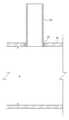
Translated fromKorean도 1은 하수 본관(10)과 가지관(20) 및 보수가 필요한 수리영역(25)을 개략적으로 나타내는 단면도,1 is a cross-sectional view schematically showing the sewage
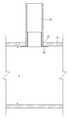
도 2는 본 발명에 따른 보수재를 이용한 대형 하수관의 보수장치가 팽창되기 전 상태의 개략적인 측단면도,Figure 2 is a schematic side cross-sectional view of a state before the expansion of the repair device for a large sewage pipe using a repair material according to the present invention,
도 3a는 도 2에 도시된 대형 하수관의 보수장치가 팽창된 상태의 개략적인 측단면도,Figure 3a is a schematic side cross-sectional view of the state in which the repair device of the large sewage pipe shown in Figure 2 is inflated,
도 3b는 도 3a에 도시된 보수장치의 종방향 단면도,Figure 3b is a longitudinal cross-sectional view of the repair device shown in Figure 3a,
도 4는 도 3에 도시된 대형 하수관의 보수장치가 수축된 상태의 개략적인 측단면도,4 is a schematic side cross-sectional view of a state in which the repair device for the large sewage pipe shown in FIG. 3 is contracted;
도 5는 수리영역(25)에 본 발명에 따른 보수가 완료되어 가지관 보수재(50)가 수리영역(25)에 설치된 상태를 나타내는 측단면도,5 is a side cross-sectional view showing a state in which the repair according to the present invention is completed in the
도 6은 본 발명에서 사용되는 가지관 보수재(50)의 사시도이다.6 is a perspective view of the branch
* 도면의 주요 부분에 대한 부호의 설명 *Explanation of symbols on the main parts of the drawings
10 : 하수 본관, 20 : 가지관,10: sewage main building, 20: branch pipe,
25 : 수리영역, 30 : 제 1 지지대,25: repair area, 30: the first support,
32 : 지지판, 34 : 공기밸브,32: support plate, 34: air valve,
36 : 팽창부, 40 : 내부지지관,36: expansion portion, 40: internal support pipe,
42 : 상부판, 44 : 하부판,42: upper plate, 44: lower plate,
46 : 빈공간, 50 : 가지관 보수재,46: empty space, 50: branch pipe repair material,
52 : 가지관 펠트부, 54 : 가지관 PVC 시트부,52: branch pipe felt portion, 54: branch pipe PVC sheet portion,
56 : 본관 PVC 시트부, 58 : 본관 펠트부,56: main PVC sheet, 58: main felt section,
60 : 제 2 지지대, 62 : 볼트,60: second support, 62: bolt,
64 : 하부지지대, d : 본관의 내경.64: lower support, d: inner diameter of the main building.
본 발명은 보수재를 이용한 하수관의 보수장치 및 보수방법에 관한 것이고, 보다 상세하게는 보수재를 이용한 대형 하수관의 보수장치 및 보수방법에 관한 것이다.The present invention relates to a repair device and a repair method of a sewage pipe using a repair material, and more particularly, to a repair device and a repair method of a large sewage pipe using a repair material.
하수 관로는 하수시설에 사용되며, 주철관, 콘크리트관 합성수지의 재질로 형성된 다수개의 관들이 연결되면서 하수 관로를 형성하여 지하에 매설하여 생활하수 및 산업용 등의 오염된 하수 등이 관로를 타고 흘러 하수종말처리장에서 집합하여 정화된 후 처리된다.Sewage pipes are used in sewage facilities, and a number of pipes made of cast resin pipes and concrete pipes are made of synthetic resins, forming sewage pipes and buried underground, where sewage and industrial polluted sewage flows through the pipe It is collected at the processing plant, purified and then processed.
한편 최근에는 자연보호 및 환경오염을 방지하며 자연을 보호하는 차원에서 생활 폐수인 하수를 일반가정 등에서 처음 배수된 후 하수종말처리장에 도달하기 전에 중간에서 누수되어 지하수 또는 토양을 오염시키지 않도록 세심한 주의를 요하고 있음에도, 지하에 매설된 콘크리트 하수 관로가 노후화하여 크랙 또는 구멍이 발생하거나 지반의 부동 침하 및 관로 이음부 등으로 콘크리트 하수 관로의 단차(單差)로 인한 간극이 발생하여 틈새로 생활하수 및 산업하수가 지하로 누수 및 유출되어 지하수 또는 토양을 오염시키게 되거나, 반대로 오염 안된 깨끗한 지하수가 하수관로에 침수하여 지하수의 낭비를 초래하게 된다. 이에 따라, 지하에 매설된 하수관로에 구멍이 발생하거나 파손되어 하수가 유출되어 지하수 또는 토양의 오염을 방지하기 위해서는 손상된 하수 관로를 보수하여 오염된 하수가 지하로 유출되는 것을 방지하여야 하는데, 과거에는 지하를 파고 매설된 하수 관로를 들어내고 새로운 관로로 연결작업하고 땅을 메꾸는 방법으로 하수관로보수를 하여 과다한 경비지출과 시간도 많이 걸리고 통행에 불편이 많았다.Recently, in order to protect nature and prevent environmental pollution, in order to protect the nature, sewage, which is the domestic wastewater, is first drained from ordinary households, etc. before being reached to the sewage treatment plant, so that careful attention is not taken to contaminate groundwater or soil. In spite of the need, concrete sewage pipelines buried underground cause cracks or holes to occur or gaps due to stepping of concrete sewer pipelines due to floating settlements and pipe joints in the ground. Industrial sewage leaks and leaks underground, contaminating groundwater or soil, or, conversely, clean, uncontaminated groundwater floods the sewer line, causing waste of groundwater. Accordingly, in order to prevent contamination of groundwater or soil due to the occurrence of holes or breakage in underground sewage pipes and damage, sewage pipes must be repaired to prevent the contaminated sewage from leaking underground. Excessive expenditure and time consuming and traffic was inconvenient by digging out the sewage pipes which were dug up and lifting the sewer pipes, connecting them with new ones, and repairing the sewage pipes by filling the ground.
근년에 선진국에서는 여러 가지의 비굴착 방법으로 하수관로를 보수하는 공법이 개발되어 소개되어 왔고, 최근에는 우리나라도 하수관로의 손상에 의한 지하수 및 토양의 오염에 의한 극심한 피해에 대하여 많은 관심을 갖게 되었고 이에 따라 손상된 하수관로의 보수에 관심을 두고 있는 실정으로, 이의 개선책으로 손상된 하수관로의 보수를 위하여, 지수제 충진공법, 에폭시 도포공법, 보강 라이닝공법, 지수고무링 삽입공법이 소개되어 적용하여 왔다.In recent years, developed countries have been developed and introduced a method for repairing sewage pipelines by various non-excavation methods, and recently, Korea has been interested in the severe damage caused by groundwater and soil pollution caused by damage to sewage pipelines. As a situation of interest in repairing damaged sewage pipes, as an improvement measure for repairing damaged sewage pipes, an index filling method, an epoxy coating method, a reinforcing lining method, and an index rubber ring insertion method have been introduced and applied.
특히, 직경이 작은 관에 대해서는 패커 등을 이용하여 수리하는 방법이 제안되었다. 본 출원인에 의한 대한민국 특허출원 제 2005-87130 호 및 특허출원 제 2005-96805 호가 대표적인 예가 될 수 있다.In particular, a method of repairing a pipe having a small diameter using a packer or the like has been proposed. Korean Patent Application No. 2005-87130 and Patent Application No. 2005-96805 by the applicant may be representative examples.
그러나, 직경(d)이 450 mm ~ 1,200 mm 인 대형 하수본관에 대해서는 종래의 패커로는 길이가 미치지 못하는 한계가 있었다. 즉, 도 1은 대형 하수 본관(10)과 가지관(20) 및 보수가 필요한 수리영역(25)을 개략적으로 나타내는 단면도이다. 도 1에 도시된 바와 같이, 보수가 필요한 수리영역(25)은 하수 본관(10)과 가지관(20)의 연결 부위이다. 그러나, 종래의 패커를 대형 하수관의 내경에 맞게 제작할 경우, 지나치게 크고 무거워서 동작이나 운반이 어렵다는 단점이 있었다.However, for large sewage main pipes having a diameter (d) of 450 mm to 1,200 mm, there is a limit that the length of the conventional packer does not reach. That is, FIG. 1 is sectional drawing which shows schematically the large sewage
따라서, 대형 하수본관의 보수에 관하여 장비가 단순하여 취급이 용이하고, 시공이 간편한 기술의 개발에 관하여 많은 연구가 진행되고 있다.Therefore, a lot of researches have been conducted on the development of a technology that is simple to handle and easy to install due to the simple equipment for repairing a large sewage main building.
따라서, 본 발명은 이와 같은 문제점을 해결하기 위하여 안출된 것으로, 본 발명의 제 1 목적은, 직경이 450 mm ~ 1,200 mm 또는 그 이상의 대형 하수본관에 대하여 가지관과의 연결부위를 수리할 수 있는 보수재를 이용한 대형 하수관의 보수장치 및 보수방법을 제공하는 것이다.Accordingly, the present invention has been made to solve such a problem, the first object of the present invention, the large sewage main pipe diameter of 450 mm to 1,200 mm or more can repair the connection portion with the branch pipe It is to provide a repair device and a repair method for a large sewage pipe using a repair material.
본 발명의 제 2 목적은, 직경이 450 mm ~ 1,200 mm 또는 그 이상의 대형 하수본관에 대하여 장비의 취급, 설치 및 분해, 이동 등이 용이한 보수재를 이용한 대형 하수관의 보수장치 및 보수방법을 제공하는 것이다.It is a second object of the present invention to provide a repair apparatus and a repairing method for a large sewage pipe using a repair material that is easy to handle, install, disassemble and move equipment to a large sewage main pipe having a diameter of 450 mm to 1,200 mm or more. will be.
상기와 같은 본 발명의 목적은,The object of the present invention as described above,
대형 본관(10)과 가지관(20)의 연결부위의 내경에 부착되는 가지관 보수재(50);Branch
가지관 보수재(50)의 내면에 밀착되어, 내부압력에 따라 팽창 또는 수축하는 팽창부(36);An inflating
팽창부(36)를 지지하는 제 1 지지대(30); 및A
일측이 제 1 지지대(30)와 연결 또는 분리 가능하고, 타측이 대형 본관(10)의 내면에 지지되는 제 2 지지대(60);로 구성되는 것을 특징으로 하는 보수재를 이용한 대형 하수관의 보수장치에 의해 달성될 수 있다.On one side is connected to or detachable from the
그리고, 가지관 보수재(50)는, 가지관(20)의 내경에 접착되는 가지관 PVC 시트부(54);And the branch
가지관 PVC 시트부(54)의 일단으로부터 일체로 연장되어 형성된 환형 본관 PVC 시트부(56);An annular main
가지관 PVC 시트부(54)의 내경에 삽입되는 가지관 펠트부(52);Branch pipe felt
가지관 펠트부(52)의 일단으로부터 일체로 연장되어 형성된 환형 본관 펠트부(58);로 구성되는 것이 바람직하다.It is preferable that it consists of; the annular main pipe felt
또한, 팽창부(36)는 팽창부(36)와 제 1 지지대(30) 사이에 구비되는 하부판(44);In addition, the
팽창부(36)의 빈공간(46)에 구비되고, 가지관(20) 내부에 삽입 가능한 외경을 갖는 상부판(42);An
팽창부(36)의 빈공간(46) 내부에 구비되고, 하부판(44)과 상부판(42) 사이를 연결하는 내부지지관(40)을 더 포함하는 것이 더욱 바람직하다.More preferably, it further includes an
뿐만 아니라, 팽창부(36)는 고무재질이고, 일측으로 공기밸브(34)가 더 구비 되어 있는 것이 가장 바람직하다.In addition, the
또한, 제 1 지지대(30)와 제 2 지지대(60)는 관형이며,In addition, the
제 1 지지대(30)의 외경이 제 2 지지대(60)의 내경으로 삽입되거나 제 2 지지대(60)의 외경이 제 1 지지대(30)의 내경으로 삽입 가능한 외경을 갖고,The outer diameter of the
제 1, 2 지지대(30, 60)는 볼트(60)에 의해 연결되는 것이 가장 바람직하다.Most preferably, the first and
그리고, 제 2 지지대(60)의 타측과 대형본관(10) 사이에는 하부지지대(64)가 더 구비될 수 있다.The
상기와 같은 본 발명의 목적은 또 다른 카테고리로서, 팽창 가능한 팽창부(36)의 외면에 가지관 보수재(50)를 위치시키는 단계(S100);As another object of the present invention as described above, the step (S100) for positioning the branch
대형 본관(10)과 가지관(20)이 연결된 수리영역(25)에서 가지관(20)의 내부로 팽창부(36)의 일부를 삽입하는 단계(S200);Inserting a part of the
팽창부(36)의 지지하는 제 1 지지대(30)에 제 2 지지대(60)를 연결하면서 제 1, 2 지지대(30, 60)의 길이가 대형 본관(10)의 내경에 상당하는 길이가 되도록 높이를 조절하여 고정하는 지지단계(S300);While connecting the
팽창부(36)의 일측에 구비된 공기밸브(34)를 통해 공기를 주입하여 팽창부(36)를 팽창시킴으로써 가지관 보수재(50)를 수리영역(25)에 밀착시키는 밀착단계(S400); 및A close step (S400) of injecting air through the
공기밸브(34)를 통해 공기를 배출시킴으로서 팽창부(36)를 수축시키고, 이로써 팽창부(36)와 가지관 보수재(50)를 분리시키는 단계(S500);로 구성되는 것을 특징으로 하는 보수재를 이용한 대형 하수관의 보수방법에 의해 달성될 수 있다.Reducing the
그리고, 밀착단계(S400)에서 공기의 주입은 점진적으로 주입되고, 그리고And, the injection of air in the adhesion step (S400) is gradually injected, and
가지관 보수재(50)가 수리영역(25)에 완전히 밀착될 수 있도록 소정 시간동안 밀착상태를 유지하는 유지단계(S450)를 더 포함하는 것이 좋다.It is preferable to further include a holding step (S450) for maintaining a close state for a predetermined time so that the branch
본 발명의 그 밖의 목적, 특정한 장점들 및 신규한 특징들은 첨부 도면들과 관련되어 설명되는 이하의 상세한 설명과 바람직한 실시예들로부터 더욱 명확해질 것이다.Other objects, specific advantages and novel features of the invention will become more apparent from the following detailed description and the preferred embodiments described in conjunction with the accompanying drawings.
이하에서는 본 발명의 일 실시예에 따른 보수재를 이용한 대형 하수관의 보수장치의 구성에 관하여 첨부된 도면을 참조하여 상세히 설명하도록 한다.Hereinafter, with reference to the accompanying drawings with respect to the configuration of the repair device for a large sewage pipe using a repair material according to an embodiment of the present invention will be described in detail.
우선, 본 발명에서 공통적으로 사용되는 "가지관"이란 하수 본관에 연결되는 관으로서, 일반적으로 하수 본관 보다는 내경이 작다.First, the "branch pipe" commonly used in the present invention is a pipe connected to the sewage main pipe, and generally has an inner diameter smaller than that of the sewage main pipe.
도 2는 본 발명에 따른 보수재를 이용한 대형 하수관의 보수장치가 팽창되기 전 상태의 개략적인 측단면도이다. 도 2에 도시된 바와 같이, 본 발명의 보수장치는 크게 팽창부분과 지지부분으로 나누어질 수 있다.Figure 2 is a schematic side cross-sectional view of the state before the expansion of the repair device for a large sewage pipe using a repair material according to the present invention. As shown in Figure 2, the repair device of the present invention can be largely divided into an expansion portion and a support portion.
팽창부분에는 팽창부(36), 가지관 보수재(50), 지지판(32), 제 1 지지대(30) 등으로 구성되고, 지지부분은 제 2 지지대(60)와 하부지지대(64)로 구성된다.The expansion portion is composed of the
팽창부(36)는 고무 재질이며 내부에 공기압이 충진되어 팽창되거나 공기압이 배출됨으로서 원래 크기로 수축될 수 있다. 이를 위해 팽창부(36)의 일측으로는 공기밸브(34)가 구비되며, 내부는 빈공간(46)을 형성한다.The
특히, 팽창부(36)의 내부에는 상부판(42)과 하부판(44) 그리고, 내부지지관 (40)이 구비된다. 즉, 내부지지관(40)의 상단에는 상부판(42)이 고정되고, 하단에는 하부판(44)이 고정된다. 이는 수축된 상태의 팽창부(36)일지라도 대략적인 형태를 유지하여 가지관 보수재(50)를 부착하기 용이하도록 하고, 초기 시공단계에서 팽창부(36)의 일부를 가지관(20) 내부로 밀어 넣는 것을 용이하게 한다.In particular, the inside of the
상부판(42)은 가지관(20) 내부에 쉽게 삽입될 정도의 외경을 가지며, 하부판(44)은 팽창부(36)의 두께 영역에 매립되도록 구성된다. 지지판(32)은 상면에 팽창부(36)가 연결되고, 하부로 제 1 지지대(30)가 연결되어, 팽창으로 인한 지지력을 팽창부(36)의 하면 전체에 골고루 분산시키는 역할을 한다. 만약 지지판(32)이 없다면 팽창에 따른 지지력이 팽창부(36)의 일부분에 집중되어 팽창부(36)가 찢어질 수도 있다.The
제 1 지지대(30)는 파이프 형상이며, 일단은 지지판(32)에 (용접) 고정되고, 타단은 제 2 지지대(60) 속으로 삽입되거나, 제 2 지지대(60)가 삽입되는 구성이다. 이와 같이 제 1, 2 지지대(30, 60)로 구분하는 것은 대형 본관(10) 내에서 이동과 설치를 편리하도록 하기 위함이다.The
지지부분중 제2 지지대(60)는 파이프 형상이며, 상단은 제1 지지대(30)에 삽입되거나, 제 1 지지대(30)가 삽입될 수 있는 정도의 직경을 갖는다. 그리고, 제 1, 2 지지대(30, 60)는 상호 볼트(62)를 통해 체결되고 분리될 수 있다.The
하부지지대(64)는 제 2 지지대(60)와 대형 본관(10) 사이에 위치하여 팽창에 따른 지지력이 대형 본관(10)의 내면에 집중되지 않고 분산되도록 도 4와 같이 곡면을 형성한다. 이로서 더욱 안정된 지지를 가능하게 하고, 팽창부(36)의 팽창에 따른 대형본관(10)의 내부 손상을 방지하는 역할을 한다.The
도 6은 본 발명에서 사용되는 가지관 보수재(50)의 사시도이다. 도 6에 도시된 바와 같이, 가지관 보수재(50)는 2겹으로 이루어져 있으며, 내측에는 가지관 펠트부(52)와 본관 펠트부(58)로 구성된 펠트부가 위치하고, 외측에는 가지관 PVC 시트부(54)와 본관 PVC 시트부(56)로 구성된 PVC 시트부가 위치한다. 그리고, 펠트부의 길이와 높이는 PVC 시트부에 비해 좀더 길고 높도록 성형한다. 본 발명에 사용되는 가지관 보수재(50)의 (본관, 가지관) PVC 시트부는 PVC 시트외에 고무재질로도 가능하다.6 is a perspective view of the branch
이러한 펠트부는 폴리에스테르로 성형하고, 두께는 약 3 mm 정도이다. 가지관 펠트부(52)의 내경은 가지관의 내경에 따라 75 mm ~ 200 mm 범위이고, 높이는 약 150 mm 내에서 성형한다. 본관 펠트부(58)는 반경 길이가 약 150 mm 정도가 되도록 한다. 그러나, 이러한 예시와 설명은 일예에 불과한 것으로서, 대형 본관(10)과 가지관(20)의 크기에 따라 얼마든지 조정할 수 있다.This felt part is molded from polyester, and the thickness is about 3 mm. The inner diameter of the branch pipe felt
이하에서는 상기와 같은 구성을 갖는 보수장치의 구체적인 보수방법에 대해 첨부된 도면을 참조하여 상세히 설명하도록 한다.Hereinafter, with reference to the accompanying drawings for a specific repair method of the repair device having the configuration as described above will be described in detail.
(설치 과정)(Installation process)
우선, 도 2는 본 발명에 따른 보수재를 이용한 대형 하수관의 보수장치가 팽창되기 전상태의 개략적인 측단면도이다. 도 2에 도시된 바와 같이, 압력이 작용하지 않는 상태의 팽창부(36)의 외면에 박리가 용이하도록 박막 비닐을 권취한다. 그 다음, 가지관 보수재(50)를 위치시킨다(S100).First, Figure 2 is a schematic side cross-sectional view of the state before the expansion of the repair device for a large sewage pipe using a repair material according to the present invention. As shown in FIG. 2, the thin film vinyl is wound around the outer surface of the expanded
그 다음, 가지관 보수재(50)의 외면에 접착제와 경화제를 도포한다. 접착제는 가지관 보수재(50)와 본관(10) 및 가지관(20) 사이의 접착과 접착후 영구적인 경화를 위한 것이다. 보다 구체적으로는 관내면에 자일렌 계통의 프라이머를 스크래퍼 또는 페인트 브러쉬를 이용하여 도포한 PVC 시트부가 접착되도록 한다. 또한, 펠트부에는 폴리우레탄 레진 또는 F.R.P. 레진을 함침시킨다. 이와 같은 과정을 통해 보수재(50)의 고정이 완료된다.Next, an adhesive and a hardener are applied to the outer surface of the branch
그 다음, 대형 본관(10)과 가지관(20)이 연결된 수리영역(25)에서 가지관(20)의 내부로 팽창부(36)의 일부를 삽입한다(S200). 이와 같은 삽입은 작업자에 의해 이루어진다. 이 때, 작업자는 제 1 지지대(30)를 잡고, 가지관(20) 내부로 내부지지관(40)이 삽입되는 느낌으로 삽입을 한다.Next, a part of the
그 다음, 팽창부(36)의 지지하는 제 1 지지대(30)에 제 2 지지대(60)를 연결하면서 제 1, 2 지지대(30, 60)의 총길이가 대형 본관(10)의 내경에 상당하는 길이가 되도록 높이를 조절하여 고정한다(S300). 이 때, 고정은 볼트(62)를 이용한다. 이러한 상태가 도 2에 도시된 상태이다. 따라서, 팽창부(36)는 팽창에 필요한 준비가 완료되고, 보수장치는 대형 본관(10) 내에서 안정된 자세를 확보하게 된다.Then, while connecting the
(팽창 과정)(Expansion process)
도 3a는 도 2에 도시된 대형 하수관의 보수장치가 팽창된 상태의 개략적인 측단면도이고, 도 3b는 도 3a에 도시된 보수장치의 종방향 단면도이다. 도 3a 및 도 3b에 도시된 바와 같이, 공기밸브(34)를 통해 압축된 공기가 유입된다. 따라서, 팽창부(36)는 대형 본관(10)과 가지관(20)의 내경에 밀착될 수 있을 정도로 충분히 팽창한다. 이 때, 압축된 공기는 외부로부터 별도의 압축기(미도시)를 통해 공급받으며, 유압이나 물을 펌프로 공급함으로서 팽창시킬 수도 있다.FIG. 3A is a schematic side cross-sectional view of an expanded state of the repair device for the large sewage pipe shown in FIG. 2, and FIG. 3B is a longitudinal cross-sectional view of the repair device shown in FIG. 3A. As shown in FIGS. 3A and 3B, compressed air is introduced through the
팽창된 상태에서는 가지관 보수재(50)가 팽창부(36)에 밀려 대형 본관(10)과 가지관(20)의 내경에 강하게 밀착된다. 이 때, 공기는 안전을 위해 서서히 점진적으로 주입한다. 그리고, 팽창부(36)가 완전히 팽창된 후에는 가지관 보수재(50)가 수리영역(25)에 완전히 밀착될 수 있도록 소정 시간동안 밀착상태를 유지한다(S450). 팽창정도는 가지관 보수재(50)가 수리영역(25)에 충분히 밀착될 수 있을 정도로 충분한 공압(예를 들어, 1.5 kg/cm2 ~ 2 kg/cm2)을 인가한다. 공압을 인가하는 상태가 충분히 유지(약 2시간 정도)되도록 하여 수리영역(25)에서 접착과 경화가 충분히 이루어지도록 한다.In the expanded state, the branch
(수축 과정)(Contraction process)
도 4는 도 3에 도시된 대형 하수관의 보수장치가 수축된 상태의 개략적인 측단면도이다. 도 4에 도시된 바와 같이, 공기밸브(34)를 개방하여 공기를 배출시키면, 팽창부(36)와 가지관 보수재(50)가 이격되면서, 가지관 보수재(50)는 수리영역(25)에 밀착된 상태를 유지하고, 팽창부(36)는 도 2와 같이 원래 형태로 복원된다(S500).4 is a schematic side cross-sectional view of a state in which the repair device for the large sewage pipe shown in FIG. 3 is in a contracted state. As shown in FIG. 4, when the
그 다음, 볼트(62)를 제거하고, 제 2 지지대(60)를 철거한 다음, 제 1 지지대(30)를 서서히 빼내 팽창부(36)의 일부가 가지관(20)에서 빠져 나오도록 한다. 그 다음, 제 1 지지대(30)와 연결된 팽창부(36)를 철거함으로서 시공이 완료된다.Then, the
도 5는 수리영역(25)에 본 발명에 따른 보수가 완료되어 가지관 보수재(50)가 수리영역(25)에 설치된 상태를 나타내는 측단면도이다. 도 5에 도시된 바와 같이, 수리영역(25)에 직접적으로 PVC 시트부(54, 56)가 접촉되며, 그 배면을 펠트부(52, 54)가 밀착되도록 접착되어 고정된다. PVC 시트부(54, 56)는 수리영역(25)의 방수를 위한 것이고, 펠트부(52, 54)는 PVC 시트부(54, 56)를 보호하고 보강하기 위한 것이다.5 is a side cross-sectional view showing a state in which the repair according to the present invention is completed in the
이와 같은 본 발명의 실시예에 따른 손상된 하수 관로의 보수방법에 의하면, 직경이 450 mm ~ 1,200 mm 또는 그 이상의 대형 하수본관에 대하여 가지관과의 연결부위를 수리할 수 있다. 이로 인해, 대형 하수관 연결부위의 벌어짐, 이음부 파손, 관 크렉 등에 의하여 누수 또는 침수되는 것을 용이하게 차단하여 지수를 하면서 손상된 하수 관로를 견고하게 보강할 수 있다.According to the repair method of the damaged sewage pipe according to the embodiment of the present invention, it is possible to repair the connection portion with the branch pipe for the large sewage main pipe diameter 450 mm ~ 1,200 mm or more. Thus, it is possible to easily reinforce the damaged sewage pipe while making it easy to prevent leakage or inundation due to the opening of the large sewer pipe connection part, the joint breakage, the pipe crack, and the like.
그리고, 직경이 450 mm ~ 1,200 mm 또는 그 이상의 대형 하수본관에 대하여 장비의 취급, 설치 및 분해, 이동 등이 용이하다.In addition, it is easy to handle, install, disassemble and move equipment to large sewage main pipes having a diameter of 450 mm to 1,200 mm or more.
비록 본 발명이 상기에서 언급한 바람직한 실시예와 관련하여 설명되어졌지만, 본 발명의 요지와 범위로 부터 벗어남이 없이 다른 다양한 수정 및 변형이 가능한 것은 당업자라면 용이하게 인식할 수 있을 것이며, 이러한 변경 및 수정은 모두 첨부된 특허청구의 범위에 속함은 자명하다.Although the present invention has been described in connection with the above-mentioned preferred embodiments, it will be readily apparent to those skilled in the art that various other modifications and variations can be made without departing from the spirit and scope of the invention. It is obvious that all modifications fall within the scope of the appended claims.
Claims (8)
Translated fromKoreanPriority Applications (1)
| Application Number | Priority Date | Filing Date | Title |
|---|---|---|---|
| KR1020060030337AKR100665278B1 (en) | 2006-04-04 | 2006-04-04 | Repair device for large sewage pipes using repair material |
Applications Claiming Priority (1)
| Application Number | Priority Date | Filing Date | Title |
|---|---|---|---|
| KR1020060030337AKR100665278B1 (en) | 2006-04-04 | 2006-04-04 | Repair device for large sewage pipes using repair material |
Publications (1)
| Publication Number | Publication Date |
|---|---|
| KR100665278B1true KR100665278B1 (en) | 2007-01-09 |
Family
ID=37867047
Family Applications (1)
| Application Number | Title | Priority Date | Filing Date |
|---|---|---|---|
| KR1020060030337AExpired - Fee RelatedKR100665278B1 (en) | 2006-04-04 | 2006-04-04 | Repair device for large sewage pipes using repair material |
Country Status (1)
| Country | Link |
|---|---|
| KR (1) | KR100665278B1 (en) |
Cited By (3)
| Publication number | Priority date | Publication date | Assignee | Title |
|---|---|---|---|---|
| KR101041024B1 (en)* | 2010-08-12 | 2011-06-20 | 김민영 | Repair of damaged parts of sewage pipe inside manhole |
| KR101636470B1 (en) | 2015-11-11 | 2016-07-06 | 김도환 | A pipe repairing apparatus and method for repairing link part of main pipe and link pipe |
| KR102339876B1 (en)* | 2020-08-19 | 2021-12-14 | 정지훈 | Repairing apparatus and method for pipe joint in manhole |
Citations (5)
| Publication number | Priority date | Publication date | Assignee | Title |
|---|---|---|---|---|
| JPH05154914A (en)* | 1991-12-06 | 1993-06-22 | Asahi Tec Corp | Device and engineering method for repairing pipe line |
| JPH0926081A (en)* | 1995-07-13 | 1997-01-28 | Ashimori Ind Co Ltd | Repair device for branch of pipe |
| JP2001108180A (en)* | 1999-10-13 | 2001-04-20 | Sekisui Chem Co Ltd | Pipe repairing material, pipe repairing device and pipe repairing method |
| KR20030048656A (en)* | 2001-12-12 | 2003-06-25 | 동도기공 주식회사 | Branchpipe-liner of revival pipe and its lining system, its lining method |
| JP2005140341A (en)* | 2005-02-16 | 2005-06-02 | Ashimori Ind Co Ltd | Repair method for branching pipes |
- 2006
- 2006-04-04KRKR1020060030337Apatent/KR100665278B1/ennot_activeExpired - Fee Related
Patent Citations (5)
| Publication number | Priority date | Publication date | Assignee | Title |
|---|---|---|---|---|
| JPH05154914A (en)* | 1991-12-06 | 1993-06-22 | Asahi Tec Corp | Device and engineering method for repairing pipe line |
| JPH0926081A (en)* | 1995-07-13 | 1997-01-28 | Ashimori Ind Co Ltd | Repair device for branch of pipe |
| JP2001108180A (en)* | 1999-10-13 | 2001-04-20 | Sekisui Chem Co Ltd | Pipe repairing material, pipe repairing device and pipe repairing method |
| KR20030048656A (en)* | 2001-12-12 | 2003-06-25 | 동도기공 주식회사 | Branchpipe-liner of revival pipe and its lining system, its lining method |
| JP2005140341A (en)* | 2005-02-16 | 2005-06-02 | Ashimori Ind Co Ltd | Repair method for branching pipes |
Cited By (3)
| Publication number | Priority date | Publication date | Assignee | Title |
|---|---|---|---|---|
| KR101041024B1 (en)* | 2010-08-12 | 2011-06-20 | 김민영 | Repair of damaged parts of sewage pipe inside manhole |
| KR101636470B1 (en) | 2015-11-11 | 2016-07-06 | 김도환 | A pipe repairing apparatus and method for repairing link part of main pipe and link pipe |
| KR102339876B1 (en)* | 2020-08-19 | 2021-12-14 | 정지훈 | Repairing apparatus and method for pipe joint in manhole |
Similar Documents
| Publication | Publication Date | Title |
|---|---|---|
| US9562339B2 (en) | Apparatus and method for sealing pipes and underground structures | |
| KR100588821B1 (en) | Sewage pipe partial repair device with packer capable of uniform expansion | |
| US8240340B2 (en) | Hydrophilic end seal | |
| US8636036B2 (en) | Apparatus and method for sealing pipes | |
| CA2868039C (en) | System for renovating a sewer manhole | |
| KR100697718B1 (en) | Sewage pipe furnace unexcavated part repair device using PCC and its construction method | |
| KR100945832B1 (en) | Piping repairing pelt and repairing method thereby | |
| US8651145B2 (en) | End seal | |
| US20080075538A1 (en) | Method and apparatus for repairing underground pipes | |
| US10683959B2 (en) | Method and apparatus for repairing a length of pipe or a main/lateral pipe junction | |
| KR100665278B1 (en) | Repair device for large sewage pipes using repair material | |
| KR100649132B1 (en) | Repair device for sewage branch pipe using repair material | |
| AU2016204120B2 (en) | Apparatus and method for sealing pipes and underground structures |
Legal Events
| Date | Code | Title | Description |
|---|---|---|---|
| A201 | Request for examination | ||
| PA0109 | Patent application | St.27 status event code:A-0-1-A10-A12-nap-PA0109 | |
| PA0201 | Request for examination | St.27 status event code:A-1-2-D10-D11-exm-PA0201 | |
| A302 | Request for accelerated examination | ||
| PA0302 | Request for accelerated examination | St.27 status event code:A-1-2-D10-D17-exm-PA0302 St.27 status event code:A-1-2-D10-D16-exm-PA0302 | |
| D13-X000 | Search requested | St.27 status event code:A-1-2-D10-D13-srh-X000 | |
| D14-X000 | Search report completed | St.27 status event code:A-1-2-D10-D14-srh-X000 | |
| E902 | Notification of reason for refusal | ||
| PE0902 | Notice of grounds for rejection | St.27 status event code:A-1-2-D10-D21-exm-PE0902 | |
| E13-X000 | Pre-grant limitation requested | St.27 status event code:A-2-3-E10-E13-lim-X000 | |
| P11-X000 | Amendment of application requested | St.27 status event code:A-2-2-P10-P11-nap-X000 | |
| P13-X000 | Application amended | St.27 status event code:A-2-2-P10-P13-nap-X000 | |
| E701 | Decision to grant or registration of patent right | ||
| PE0701 | Decision of registration | St.27 status event code:A-1-2-D10-D22-exm-PE0701 | |
| GRNT | Written decision to grant | ||
| PR0701 | Registration of establishment | St.27 status event code:A-2-4-F10-F11-exm-PR0701 | |
| PR1002 | Payment of registration fee | St.27 status event code:A-2-2-U10-U11-oth-PR1002 Fee payment year number:1 | |
| PG1601 | Publication of registration | St.27 status event code:A-4-4-Q10-Q13-nap-PG1601 | |
| R18-X000 | Changes to party contact information recorded | St.27 status event code:A-5-5-R10-R18-oth-X000 | |
| PR1001 | Payment of annual fee | St.27 status event code:A-4-4-U10-U11-oth-PR1001 Fee payment year number:4 | |
| R18-X000 | Changes to party contact information recorded | St.27 status event code:A-5-5-R10-R18-oth-X000 | |
| PR1001 | Payment of annual fee | St.27 status event code:A-4-4-U10-U11-oth-PR1001 Fee payment year number:5 | |
| FPAY | Annual fee payment | Payment date:20111118 Year of fee payment:6 | |
| PR1001 | Payment of annual fee | St.27 status event code:A-4-4-U10-U11-oth-PR1001 Fee payment year number:6 | |
| LAPS | Lapse due to unpaid annual fee | ||
| PC1903 | Unpaid annual fee | St.27 status event code:A-4-4-U10-U13-oth-PC1903 Not in force date:20121229 Payment event data comment text:Termination Category : DEFAULT_OF_REGISTRATION_FEE | |
| R18-X000 | Changes to party contact information recorded | St.27 status event code:A-5-5-R10-R18-oth-X000 | |
| PC1903 | Unpaid annual fee | St.27 status event code:N-4-6-H10-H13-oth-PC1903 Ip right cessation event data comment text:Termination Category : DEFAULT_OF_REGISTRATION_FEE Not in force date:20121229 | |
| R18-X000 | Changes to party contact information recorded | St.27 status event code:A-5-5-R10-R18-oth-X000 | |
| R18-X000 | Changes to party contact information recorded | St.27 status event code:A-5-5-R10-R18-oth-X000 | |
| R18-X000 | Changes to party contact information recorded | St.27 status event code:A-5-5-R10-R18-oth-X000 | |
| R18-X000 | Changes to party contact information recorded | St.27 status event code:A-5-5-R10-R18-oth-X000 | |
| P22-X000 | Classification modified | St.27 status event code:A-4-4-P10-P22-nap-X000 | |
| R18-X000 | Changes to party contact information recorded | St.27 status event code:A-5-5-R10-R18-oth-X000 | |
| PN2301 | Change of applicant | St.27 status event code:A-5-5-R10-R13-asn-PN2301 St.27 status event code:A-5-5-R10-R11-asn-PN2301 |