KR100664058B1 - Variable Capacity of Scroll Compressor - Google Patents
Variable Capacity of Scroll CompressorDownload PDFInfo
- Publication number
- KR100664058B1 KR100664058B1KR1020040089395AKR20040089395AKR100664058B1KR 100664058 B1KR100664058 B1KR 100664058B1KR 1020040089395 AKR1020040089395 AKR 1020040089395AKR 20040089395 AKR20040089395 AKR 20040089395AKR 100664058 B1KR100664058 B1KR 100664058B1
- Authority
- KR
- South Korea
- Prior art keywords
- scroll
- opening
- fixed scroll
- bypass flow
- compression
- Prior art date
- Legal status (The legal status is an assumption and is not a legal conclusion. Google has not performed a legal analysis and makes no representation as to the accuracy of the status listed.)
- Expired - Fee Related
Links
Images


Classifications
- F—MECHANICAL ENGINEERING; LIGHTING; HEATING; WEAPONS; BLASTING
- F04—POSITIVE - DISPLACEMENT MACHINES FOR LIQUIDS; PUMPS FOR LIQUIDS OR ELASTIC FLUIDS
- F04C—ROTARY-PISTON, OR OSCILLATING-PISTON, POSITIVE-DISPLACEMENT MACHINES FOR LIQUIDS; ROTARY-PISTON, OR OSCILLATING-PISTON, POSITIVE-DISPLACEMENT PUMPS
- F04C18/00—Rotary-piston pumps specially adapted for elastic fluids
- F04C18/02—Rotary-piston pumps specially adapted for elastic fluids of arcuate-engagement type, i.e. with circular translatory movement of co-operating members, each member having the same number of teeth or tooth-equivalents
- F—MECHANICAL ENGINEERING; LIGHTING; HEATING; WEAPONS; BLASTING
- F04—POSITIVE - DISPLACEMENT MACHINES FOR LIQUIDS; PUMPS FOR LIQUIDS OR ELASTIC FLUIDS
- F04C—ROTARY-PISTON, OR OSCILLATING-PISTON, POSITIVE-DISPLACEMENT MACHINES FOR LIQUIDS; ROTARY-PISTON, OR OSCILLATING-PISTON, POSITIVE-DISPLACEMENT PUMPS
- F04C28/00—Control of, monitoring of, or safety arrangements for, pumps or pumping installations specially adapted for elastic fluids
- F04C28/10—Control of, monitoring of, or safety arrangements for, pumps or pumping installations specially adapted for elastic fluids characterised by changing the positions of the inlet or outlet openings with respect to the working chamber
- F04C28/16—Control of, monitoring of, or safety arrangements for, pumps or pumping installations specially adapted for elastic fluids characterised by changing the positions of the inlet or outlet openings with respect to the working chamber using lift valves
- F—MECHANICAL ENGINEERING; LIGHTING; HEATING; WEAPONS; BLASTING
- F04—POSITIVE - DISPLACEMENT MACHINES FOR LIQUIDS; PUMPS FOR LIQUIDS OR ELASTIC FLUIDS
- F04C—ROTARY-PISTON, OR OSCILLATING-PISTON, POSITIVE-DISPLACEMENT MACHINES FOR LIQUIDS; ROTARY-PISTON, OR OSCILLATING-PISTON, POSITIVE-DISPLACEMENT PUMPS
- F04C18/00—Rotary-piston pumps specially adapted for elastic fluids
- F04C18/02—Rotary-piston pumps specially adapted for elastic fluids of arcuate-engagement type, i.e. with circular translatory movement of co-operating members, each member having the same number of teeth or tooth-equivalents
- F04C18/0207—Rotary-piston pumps specially adapted for elastic fluids of arcuate-engagement type, i.e. with circular translatory movement of co-operating members, each member having the same number of teeth or tooth-equivalents both members having co-operating elements in spiral form
- F04C18/0215—Rotary-piston pumps specially adapted for elastic fluids of arcuate-engagement type, i.e. with circular translatory movement of co-operating members, each member having the same number of teeth or tooth-equivalents both members having co-operating elements in spiral form where only one member is moving
- F—MECHANICAL ENGINEERING; LIGHTING; HEATING; WEAPONS; BLASTING
- F04—POSITIVE - DISPLACEMENT MACHINES FOR LIQUIDS; PUMPS FOR LIQUIDS OR ELASTIC FLUIDS
- F04C—ROTARY-PISTON, OR OSCILLATING-PISTON, POSITIVE-DISPLACEMENT MACHINES FOR LIQUIDS; ROTARY-PISTON, OR OSCILLATING-PISTON, POSITIVE-DISPLACEMENT PUMPS
- F04C23/00—Combinations of two or more pumps, each being of rotary-piston or oscillating-piston type, specially adapted for elastic fluids; Pumping installations specially adapted for elastic fluids; Multi-stage pumps specially adapted for elastic fluids
- F04C23/008—Hermetic pumps
Landscapes
- Engineering & Computer Science (AREA)
- Mechanical Engineering (AREA)
- General Engineering & Computer Science (AREA)
- Rotary Pumps (AREA)
- Applications Or Details Of Rotary Compressors (AREA)
Abstract
Translated fromKoreanDescription
Translated fromKorean도 1은 일반적인 스크롤 압축기의 압축 기구부를 도시한 단면도,1 is a cross-sectional view showing a compression mechanism of a general scroll compressor;
도 2는 상기 스크롤 압축기의 압축 기구부를 구성하는 고정 스크롤 랩과 선회 스크롤 랩을 도시한 평면도,2 is a plan view showing a fixed scroll wrap and a rotating scroll wrap forming the compression mechanism of the scroll compressor;
도 3은 종래 스크롤 압축기의 용량 가변장치가 구비된 스크롤 압축기의 압축 기구부를 도시한 단면도,3 is a cross-sectional view showing a compression mechanism unit of a scroll compressor equipped with a variable capacity device of a conventional scroll compressor;
도 4는 본 발명의 스크롤 압축기의 용량 가변장치의 제1 실시예가 구비된 스크롤 압축기의 압축 기구부를 도시한 단면도,4 is a cross-sectional view showing a compression mechanism unit of a scroll compressor equipped with a first embodiment of a variable capacity device of a scroll compressor of the present invention;
도 5는 본 발명의 스크롤 압축기의 용량 가변장치의 제2 실시예를 도시한 단면도,5 is a cross-sectional view showing a second embodiment of a variable displacement device of a scroll compressor of the present invention;
도 6은 본 발명의 스크롤 압축기의 용량 가변장치의 작동 상태를 도시한 단면도.6 is a cross-sectional view showing an operating state of the variable displacement device of the scroll compressor of the present invention.
<도면의 주요부분에 대한 부호의 설명><Description of the symbols for the main parts of the drawings>
12; 흡입관82; 고정 스크롤의 랩12;
84; 흡입구85; 제1 구멍84;
86; 제2 구멍92; 선회 스크롤의 랩86;
100; 개폐 수단110; 탄성 개폐 수단100; Opening and closing means 110; Elastic opening and closing means
111; 피스톤 밸브112; 스프링111;
120; 연결관F; 바이패스 유로120; Connector F; Bypass Euro
P; 압축 포켓P; Compression pocket
본 발명은 스크롤 압축기에 관한 것으로, 특히 압축기 용량을 가변시키는 구조를 간단하게 하여 크기를 감소시킬 뿐만 아니라 구성 부품을 줄일 수 있도록 한 스크롤 압축기의 용량 가변장치에 관한 것이다.BACKGROUND OF THE INVENTION 1. Field of the Invention The present invention relates to scroll compressors, and more particularly, to a variable capacity apparatus of a scroll compressor, in which a structure for varying the compressor capacity can be simplified to reduce the size as well as to reduce component parts.
일반적으로 압축기는 전기 에너지를 운동 에너지로 변환시키며 그 운동 에너지에 의해 냉매 가스를 압축하게 된다. 압축기는 냉동사이클 시스템을 구성하는 핵심 요소이며, 냉매를 압축하는 압축 매카니즘에 따라 회전식 압축기(rotary compressor), 스크롤 압축기(scroll compressor), 왕복동식 압축기(reciprocal compressor) 등 다양한 종류가 있다. 이와 같은 압축기들은 냉장고, 에어컨, 쇼케이스 등에 사용되고 있다.Generally, a compressor converts electrical energy into kinetic energy and compresses refrigerant gas by the kinetic energy. Compressors are a key component of the refrigeration cycle system, and there are various types of compressors, such as rotary compressors, scroll compressors, and reciprocal compressors, depending on a compression mechanism for compressing refrigerant. Such compressors are used in refrigerators, air conditioners and showcases.
도 1은 상기 스크롤 압축기의 압축 기구부를 도시한 단면도이고, 도 2는 상기 압축 기구부를 구성하는 고정 스크롤의 랩과 선회 스크롤의 랩을 도시한 평면도이다.BRIEF DESCRIPTION OF THE DRAWINGS Fig. 1 is a sectional view showing a compression mechanism part of the scroll compressor, and Fig. 2 is a plan view showing a wrap of a fixed scroll and a swing scroll that constitute the compression mechanism part.
이에 도시한 바와 같이, 상기 스크롤 압축기의 압축 기구부는 밀폐 용기(10)내에 장착되는 상부 프레임(20)과 일정 간격을 두고 그 밀폐 용기(10)내에 장착되는 고정 스크롤(30)과, 상기 고정 스크롤(30)과 선회 운동 가능하게 맞물리도록 상기 고정 스크롤(30)과 상부 프레임(20)사이에 위치하는 선회 스크롤(40)과, 상기 선회 스크롤(40)과 상부 프레임(20)사이에 위치하여 상기 선회 스크롤(40)의 자전을 방지하는 올담링(50)과, 상기 고정 스크롤(30)과 상기 밀폐 용기(10)에 결합되어 그 밀폐 용기(10) 내부를 고압 영역과 저압 영역으로 분리하는 고저압 분리판(11)과, 상기 고정 스크롤(30)의 상면에 장착되어 그 고정 스크롤(30)에 형성된 토출 구멍(31)을 개폐하는 토출 밸브 조립체(60)를 포함하여 구성된다.As shown in the drawing, the compression mechanism of the scroll compressor has a fixed
그리고 상기 선회 스크롤(40)은 상기 상부 프레임에 삽입되는 회전축(70)의 편심부(71)와 연결된다.The turning
그리고 상기 저압 영역에 위치하는 밀폐 용기(10)의 일측에 가스가 흡입되는 흡입관(12)이 결합되고, 상기 고압 영역에 위치하는 밀폐 용기(10)의 일측에 가스가 토출되는 토출관(13)이 결합된다.In addition, a
미설명 부호 32는 인벌류트 곡선 형상으로 돌출 형성된 고정 스크롤(30)의 랩이고, 41은 인벌류트 곡선 형상으로 돌출 형성된 선회 스크롤(40)의 랩이며, B는 부시들이고, S는 실링부재이다.
상기한 바와 같은 스크롤 압축기 압축 기구부의 작동은 다음과 같다.The operation of the scroll compressor compression mechanism unit as described above is as follows.
먼저, 전동 기구부의 회전력을 전달받아 회전축(70)이 회전하게 되면 그 회전축의 편심부(71)에 결합된 선회 스크롤(40)이 그 회전축(70)의 축 중심으로 기준 으로 선회 운동하게 된다. 상기 선회 스크롤(40)은 올담링(50)에 의해 자전이 방지되면서 선회 운동하게 된다.First, when the
상기 선회 스크롤(40)이 선회 운동함에 따라 그 선회 스크롤(40)의 랩(41)이 고정 스크롤(30)의 랩(32)과 맞물려 선회 운동하면서 그 선회 스크롤(40)의 랩(41)과 고정 스크롤(30)의 랩(32)에 의해 형성되는 복수개의 압축 포켓(P)(P)이 그 고정 스크롤(30)과 선회 스크롤(40)의 중심부로 이동함과 동시에 체적이 변화되면서 가스를 흡입하고 압축하여 고정 스크롤(30)의 토출 구멍(31)을 통해 토출시키게 된다.As the pivoting
상기 고정 스크롤(30)의 토출 구멍(31)을 통해 토출된 고온 고압의 가스는 고압 영역을 거쳐 토출관(13)을 통해 밀폐 용기(10)의 외부로 토출된다.The high temperature and high pressure gas discharged through the
한편, 상기한 바와 같은 스크롤 압축기는 보통 냉동사이클 시스템을 구성하여 주로 에어컨에 장착된다. 에어컨 운전시 그 소모 전력을 최소화하기 위하여 그 에어컨에 장착된 냉동사이클 시스템을 운전시키는 스크롤 압축기의 용량을 가변시키는 것이 요구된다.On the other hand, the scroll compressor as described above usually comprises a refrigeration cycle system is mainly mounted on the air conditioner. In order to minimize the power consumption when operating the air conditioner, it is required to vary the capacity of the scroll compressor for driving the refrigeration cycle system mounted on the air conditioner.
도 3은 종래 스크롤 압축기의 용량 가변장치의 일예가 구비된 스크롤 압축기의 압축 기구부를 도시한 단면도이다. 위의 도면과 동일한 부분에 대하여 동일한 부호를 부여하였다.3 is a cross-sectional view showing a compression mechanism unit of a scroll compressor equipped with an example of a variable capacity device of a conventional scroll compressor. The same reference numerals are given to the same parts as in the above drawings.
이에 도시한 바와 같이, 종래 스크롤 압축기의 용량 가변장치는 다음과 같다.As shown in the drawing, the variable capacity device of the conventional scroll compressor is as follows.
상기 고정 스크롤의 랩(32)과 선회 스크롤의 랩(41)에 의해 형성되는 압축 포켓(P)들 중 고정 스크롤(30)의 중간 부분에 위치하게 되는 중간 압력 상태인 중간압 압축 포켓(P)들과 그 압축 포켓(P)들로 냉매가 흡입되는 흡입측을 연결하는 바이패스 통로(K)가 상기 고정 스크롤(30)에 형성된다. 상기 바이패스 통로(K)는 상기 고정 스크롤(30)의 수평방향으로 형성된 수평 구멍(33)과 상기 고정 스크롤(30)의 수직 방향으로 형성되어 상기 수평 구멍(33)과 연통되는 수직 구멍(34)과 상기 수평 구멍(33)과 수직 구멍(34)이 연결되는 부분에 상기 고정 스크롤(30)의 상면과 연통되게 형성되는 연결 구멍(35)으로 이루어진다. 상기 고저압 분리판(11)에 상기 연결구멍(35)과 고압실이 연통되는 관통구멍이 형성된다.Medium pressure compression pocket (P) in the intermediate pressure state that is located in the middle portion of the fixed scroll (30) of the compression pocket (P) formed by the
그리고 상기 흡입관(12)과 토출관(13)을 연통시키는 제1 연결관(14)이 상기 흡입관(12)과 토출관(13)사이에 연결되고, 상기 제1 연결관(14)과 상기 바이패스 통로(K)를 연통시키는 제2 연결관(15)이 상기 제1 연결관(14)과 바이패스 통로(K)사이에 연결된다. 상기 제2 연결관(15)의 일측은 상기 바이패스 통로(K)의 연결 구멍(35)측에 결합된다.In addition, a first connecting
그리고 상기 제1 연결관(12)과 제2 연결관(15)이 연결되는 부분에 제1,2 연결관(14)(15)으로 흐르는 냉매의 흐름 방향을 조절하는 컨트롤 밸브(selecting valve)(16)가 구비되고, 상기 바이패스 통로(K)의 연결 구멍(35)에 냉매의 흐름을 제어하는 바이패스 밸브(17)가 구비된다.And a control valve (selecting valve) for controlling the flow direction of the refrigerant flowing to the first and second connecting pipes (14, 15) to the portion where the first connecting
상기한 바와 같은 스크롤 압축기의 용량 가변장치의 작동을 설명하면 다음과 같다.The operation of the variable displacement device of the scroll compressor as described above is as follows.
먼저, 스크롤 압축기가 100% 용량으로 운전될 경우, 상기 제2 연결관(15)과 토출관(13)이 연통되도록 상기 컨트롤 밸브(16)를 위치시키게 된다. 이와 같은 상태에서 스크롤 압축기가 운전하게 되면 토출관(13)과 상기 제2 연결관(15)이 연통되므로 토출관(13)으로 토출되는 고압 상태의 냉매에 의해 상기 연결 구멍(35)내에 위치하는 바이패스 밸브(17)가 압력을 받게 되어 연결 구멍(35)의 아래측으로 위치하게 되면서 수평 구멍(33)과 수직 구멍(34)을 막게 되며, 이로 인하여 냉매가 압축 포켓(P)으로 흡입되는 흡입측과 중간 압력 상태에 있는 압축 포켓(P)사이의 연통시키는 바이패스 통로(K)가 막히게 된다.First, when the scroll compressor is operated at 100% capacity, the
이와 같은 상태에서 선회 스크롤(40)의 선회 운동에 따라 선회 스크롤의 랩(41)과 고정 스크롤의 랩(32)에 의해 고정 스크롤(30)의 가장자리에서 부터 형성되는 복수개의 압축 포켓(P)들이 점점 고정 스크롤(30)의 중심으로 이동함과 동시에 체적이 감소되면서 냉매를 압축하게 된다. 이와 같은 압축 포켓(P)들은 연속적으로 형성된다.In this state, the plurality of compression pockets P formed from the edge of the
상기 스크롤 압축기가 가변 용량으로 운전하게 될 경우, 상기 상기 컨트롤 밸브(16)의 위치를 이동시켜 상기 제2 연결관(15)과 흡입관(12)을 연통시킨다. 이와 같은 상태에서 스크롤 압축기가 운전하게 되면 상기 흡입관(12)과 제2 연결관(15)이 연통되므로 상기 바이패스 밸브(17)에 작용하는 중간압력 상태의 압축 포켓(P)의 압력에 의해 연결 구멍(35)의 상측으로 이동하게 되면서 바이패스 통로(K)를 오픈시키게 된다. 상기 바이패스 통로(K)가 오픈됨에 따라 냉매가 압축 포켓(P)으로 흡입되는 흡입측과 고정 스크롤(30)의 중간 위치에 위치하는 압축 포켓(P)의 압력이 같은 상태가 된다. 이로 인하여, 그 고정 스크롤(30)의 중간 위치에 위치하는 압축 포켓(P)이 고정 스크롤(30)의 중심으로 이동함과 동시에 체적이 감소되면서 압축되어 고정 스크롤의 토출구멍(31)을 통해 토출되는 냉매의 압력은 상대적으로 낮게 된다.When the scroll compressor is operated with a variable capacity, the position of the
그러나 상기한 바와 같은 종래 스크롤 압축기의 용량 가변장치는 흡입관(12)과 토출관(13)이 제1 연결관(14)에 의해 연결되고 그 제1 연결관(14)이 제2 연결관(15)에 의해 연결되므로 전체적인 구조가 복잡하고 스크롤 압축기의 전체적인 크기가 크게 되어 에어컨내에 장착되는 설치공간이 크게 될 뿐만 아니라 설치 위치가 자유롭지 못하게 되는 문제점이 있었다.However, the variable capacity device of the conventional scroll compressor as described above, the
본 발명은 상기한 바와 같은 점을 해결하기 위한 것으로, 본 발명의 목적은 압축기의 용량을 가변시키는 구조를 간단하게 하여 크기를 감소시킬 뿐만 아니라 구성 부품을 줄일 수 있도록 한 스크롤 압축기의 용량 가변장치를 제공함에 있다.SUMMARY OF THE INVENTION The present invention has been made in view of the above-described problems, and an object of the present invention is to provide a variable capacity device of a scroll compressor which can simplify the structure of varying the capacity of the compressor to reduce the size as well as reduce the components. In providing.
또한 본 발명의 다른 목적은 용량 가변 운전시 손실을 최소화할 수 있도록 한 스크롤 압축기의 용량 가변장치를 제공함에 있다.It is another object of the present invention to provide a variable capacity device of a scroll compressor to minimize losses during variable capacity operation.
상기한 바와 같은 본 발명의 목적을 달성하기 위하여 고정 스크롤의 랩과 선회 스크롤의 랩에 의해 형성되는 압축 포켓들 중 중간 압력 상태의 압축 포켓들과 상기 압축 포켓들로 냉매가 흡입되는 흡입측을 연통시키는 바이패스 유로와, 상기 바이패스 유로를 개폐하는 개폐 수단과, 상기 바이패스 유로내에 장착되어 상기 개폐 수단에 의한 바이패스 유로의 개폐에 따라 상기 압축 포켓의 압력과 흡입측의 압력 및 자체 탄성에 의해 상기 바이패스 유로를 개폐시키는 탄성 개폐 수단을 포 함하여 구성됨을 특징으로 하는 스크롤 압축기의 용량 가변장치가 제공된다.In order to achieve the object of the present invention as described above, among the compression pockets formed by the wrap of the fixed scroll and the wrap of the swinging scroll, the compression pockets in the intermediate pressure state and the suction side where the refrigerant is sucked into the compression pockets are communicated. The bypass flow path, the opening / closing means for opening and closing the bypass flow path, and the pressure passage of the compression pocket, the pressure on the suction side, and the self-elasticity according to opening and closing of the bypass flow path by the opening and closing means. The variable capacity of the scroll compressor is provided by including an elastic opening and closing means for opening and closing the bypass flow path.
또한, 고정 스크롤의 랩과 선회 스크롤의 랩에 의해 형성되는 압축 포켓과 상기 압축 포켓으로 냉매가 흡입되는 흡입측을 연통시키는 바이패스 유로와, 상기 바이패스 유로를 개폐하는 개폐 수단을 포함하여 구성됨을 특징으로 하는 스크롤 압축기의 용량 가변장치가 제공된다.And a bypass flow passage for communicating the compression pocket formed by the wrap of the fixed scroll and the wrap of the swing scroll, the suction side through which the refrigerant is sucked into the compression pocket, and an opening / closing means for opening and closing the bypass flow passage. A variable capacity device of a scroll compressor is provided.
이하, 본 발명에 의한 스크롤 압축기의 용량 가변장치를 첨부도면에 의거하여 상세하게 설명한다.EMBODIMENT OF THE INVENTION Hereinafter, the variable capacity apparatus of the scroll compressor which concerns on this invention is demonstrated in detail based on an accompanying drawing.
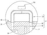
도 4는 본 발명의 스크롤 압축기 용량 가변장치의 일 실시예를 구비한 스크롤 압축기의 압축 기구부를 도시한 단면도이다.4 is a cross-sectional view showing a compression mechanism unit of the scroll compressor with one embodiment of the scroll compressor variable capacity device of the present invention.
이에 도시한 바와 같이, 먼저 스크롤 압축기의 압축 기구부는 다음과 같다. 소정 형상을 갖는 밀폐 용기(10)내에 장착되는 상부 프레임(20)과 일정 간격을 두고 그 밀폐 용기(10)내에 고정 스크롤(80)이 장착되고, 상기 고정 스크롤(80)과 선회 운동 가능하게 맞물리도록 상기 고정 스크롤(80)과 상부 프레임(20)사이에 선회 스크롤(90)이 위치하게 된다.As shown in the figure, first, the compression mechanism of the scroll compressor is as follows. A fixed
상기 고정 스크롤(80)은 소정 형상으로 형성된 몸체부(81))의 일면에 일정 두께와 높이를 갖는 인볼류트 곡선 형상의 랩(82)이 형성되고 그 몸체부(81)의 가운데 토출 구멍(83)이 형성되고 그 몸체부(81)의 일측에 흡입구(84)가 형성된다.The fixed
상기 선회 스크롤(90)은 일정 두께와 면적을 갖는 원판부(91)의 일면에 일정 두께와 높이를 갖는 인볼류트 곡선 형상의 랩(92)이 형성되고 그 원판부(91)의 타 면에 보스부(93)가 형성된다.The turning
상기 선회 스크롤(90)은 그 랩(92)이 고정 스크롤의 랩(82)과 맞물리게 상기 상부 프레임(20)과 고정 스크롤(80)사이에 삽입되며, 상기 선회 스크롤(90)이 선회 운동하게 되면 그 선회 스크롤의 랩(92)과 고정 스크롤의 랩(82)에 의해 복수개의 압축 포켓(P)들이 연속적으로 형성된다. 이때 고정 스크롤(80)의 가장 자리측에 위치하는 압축 포켓(P)들은 저압인 흡입압 상태이고 그 고정 스크롤(80)의 가운데 위치하는 압축 포켓(P)들은 고압인 토출압 상태이며 그 고정 스크롤(80)의 가장 자리와 가운데 사이에 위치하는 압축 포켓(P)들은 중간압 상태이다. 상기 선회 스크롤(90)은 상부 프레임(20)의 상면에 지지된다.The pivoting
상기 선회 스크롤(90)과 상부 프레임(20)사이에 그 선회 스크롤(90)의 자전을 방지하는 올담링(50)이 결합되고, 상기 고정 스크롤(80)의 상면에 그 고정 스크롤(80)의 토출 구멍(83)을 개폐하는 토출 밸브 조립체(60)를 구비된다.An
그리고 상기 선회 스크롤의 보스부(93)는 상기 상부 프레임(20)에 삽입되는 회전축(70)의 편심부(71)와 연결된다.In addition, the
상기 밀폐 용기(10)에 가스가 흡입되는 흡입관(12)이 관통 결합되고 그 관통된 흡입관(12)은 상기 고정 스크롤의 흡입구(84)에 결합된다. 그리고 상기 밀폐 용기(10)에 가스가 토출되는 토출관(13)이 결합된다.The
그리고 상기 고정 스크롤(80)측에 용량 가변장치가 구비된다.And a variable capacity device is provided on the fixed
상기 스크롤 압축기의 용량 가변장치의 제1 실시예는 고정 스크롤의 랩(82)과 선회 스크롤의 랩(92)에 의해 형성되는 압축 포켓(P)들 중 중간 압력 상태의 압 축 포켓(P)과 상기 압축 포켓(P)으로 냉매가 흡입되는 흡입측을 연통시키는 바이패스 유로(F)와, 상기 바이패스 유로(F)를 개폐하는 개폐 수단(100)과, 상기 바이패스 유로(F)내에 장착되어 상기 개폐 수단(100)에 의한 바이패스 유로(F)의 개폐에 따라 상기 압축 포켓(P)의 압력과 흡입측의 압력 및 자체 탄성에 의해 상기 바이패스 유로(F)를 개폐시키는 탄성 개폐 수단(110)을 포함하여 구성된다.The first embodiment of the variable displacement device of the scroll compressor comprises a compression pocket P of an intermediate pressure state among compression pockets P formed by the
상기 바이패스 유로(F)는 상기 고정 스크롤(80)의 흡입측과 그 고정 스크롤(80)의 상면을 연결시키도록 상기 고정 스크롤의 몸체부(81)에 형성되는 제1 구멍(85)과, 상기 고정 스크롤의 몸체부(81)에 형성되어 그 상기 중간 압력 상태의 압축 포켓(P)과 상기 고정 스크롤(80)의 상면을 연통시키는 제2 구멍(86)과, 상기 고정 스크롤(80)의 상면 위에 위치하여 제1 구멍(85)과 제2 구멍(86)을 연결하는 연결관(120)을 포함하여 이루어진다. 상기 제1 구멍(85)과 제2 구멍(86)은 수직 방향으로 형성된다.The bypass flow path (F) is a
상기 개폐 수단(100)은 상기 연결관(120)에 설치된다. 상기 개폐 수단(100)은 그 연결관(120)을 개폐하는 개폐 밸브인 것이 바람직하다.The opening and closing means 100 is installed in the connecting
상기 연결관(120)은 절곡된 형태로 형성되며 그 양측 단부에 플랜지부(121)가 각각 구비된다. 상기 고정 스크롤(80)의 상면에 상기 플랜지부(121)와 상응하는 형상과 일정 깊이를 갖는 결합홈(87)이 형성된다. 상기 결합홈(87)은 상기 제1 구멍(85)과 제2 구멍(86)의 가장자리에 각각 형성된다.The connecting
그리고 상기 연결관의 플랜지부(121)들이 제1 구멍(85)과 제2 구멍(86)의 가장자리에 형성된 결합홈(87)에 삽입되고 그 플랜지부(121)들에 나사(미도시)가 각 각 체결된다. 상기 플랜지부(121)와 결합홈(87)의 바닥면사이에 패킹(122)이 삽입됨이 바람직하다.And the
상기 제2 구멍(86)의 내부에 그 제2 구멍(86)의 내경보다 큰 내경과 일정 길이를 갖도록 형성되어 상기 탄성 개폐 수단(100)이 장착되는 삽입 공간(88)이 구비된다. 상기 제2 구멍(86)과 삽입 공간(88)의 연결 부분이 그 제2 구멍(86)의 외주면과 수직면을 이루도록 단차면(89)이 평면으로 형성된다.An
상기 탄성 개폐 수단(110)은 상기 제2 구멍(86)의 삽입 공간(88)에 움직임 가능하게 삽입되어 그 제2 구멍(86)을 개폐하는 환봉 형태의 피스톤 밸브(111)와, 상기 삽입 공간(88)내에 삽입되어 상기 피스톤 밸브(111)를 탄성 지지하는 스프링(112)을 포함하여 구성된다. 상기 피스톤 밸브(111)의 외경은 상기 삽입 공간(88)의 내경보다 작고 상기 제2 구멍(86)의 내경보다 크게 형성된다.The elastic opening and closing means 110 is inserted into the insertion space (88) of the second hole (86) movably to open and close the
상기 피스톤 밸브(111)가 상기 삽입 공간(88)내에 삽입되고 그 피스톤 밸브(111)위에 상기 스프링(112)이 삽입된다. 그리고 상기 스프링(112)은 별도의 부재에 의해 지지된다.The
또한, 본 발명의 스크롤 압축기의 용량 가변장치의 제2 실시예는, 도 5에 도시한 바와 같이, 고정 스크롤의 랩(82)과 선회 스크롤의 랩(92)에 의해 형성되는 중간 압력 상태의 압축 포켓(P)과 상기 압축 포켓(P)으로 냉매가 흡입되는 흡입측을 연통시키는 바이패스 유로(F)와, 상기 바이패스 유로(F)를 개폐하는 개폐 수단(100)을 포함하여 구성된다.In addition, in the second embodiment of the variable displacement device of the scroll compressor of the present invention, as shown in Fig. 5, the compression in the intermediate pressure state formed by the
상기 바이패스 유로(F)는 상기 고정 스크롤(80)의 흡입측과 그 고정 스크롤 (80)의 상면을 연결시키도록 상기 고정 스크롤(80)에 형성되는 제1 구멍(85)과, 상기 고정 스크롤(80)에 형성되어 그 상기 중간 압력 상태의 압축 포켓(P)과 상기 고정 스크롤(80)의 상면을 연결시키는 제2 구멍(86)과, 상기 제1 구멍(85)과 제2 구멍(86)을 연결하는 연결관(120)을 포함하여 이루어진다.The bypass flow path F has a
상기 개폐 수단(100)은 상기 연결관(120)에 장착된다. 상기 개폐 수단(100)은 그 연결관(120)을 개폐시키는 개폐 밸브로 이루어지는 것이 바람직하다.The opening and closing means 100 is mounted to the
한편, 상기 바이패스 유로(F)의 다른 변형예로 상기 고정 스크롤의 몸체부(81)에 상기 압축 포켓(P)과 흡입구를 연결하는 하나의 연통 구멍이 형성되어 이루어질 수 있다.Meanwhile, as another modification of the bypass flow path F, one communication hole may be formed in the
이하, 본 발명의 스크롤 압축기 용량 가변장치의 작용효과를 설명하면 다음과 같다.Hereinafter, the operational effects of the scroll compressor variable capacity device of the present invention will be described.
먼저, 상기 스크롤 압축기의 압축기구부의 작동은 다음과 같다.First, the operation of the compression mechanism of the scroll compressor is as follows.
전동 기구부의 회전력이 회전축(70)을 통해 선회 스크롤(90)에 전달되면 그 선회 스크롤(90)이 고정 스크롤(80)과 맞물려 회전축(70)의 중심을 기준으로 선회 운동하게 된다. 상기 선회 스크롤(90)은 올담링(50)에 의해 자전이 방지되면서 선회 운동하게 된다.When the rotational force of the transmission mechanism is transmitted to the turning
상기 선회 스크롤(90)이 선회 운동함에 따라 그 선회 스크롤의 랩(92)이 고정 스크롤의 랩(82)과 맞물려 선회 운동하면서 그 선회 스크롤의 랩(92)과 고정 스크롤의 랩(82)에 의해 형성되는 복수개의 압축 포켓(P)이 그 고정 스크롤(80)의 중심부로 이동함과 동시에 체적이 변화되면서 가스를 흡입하고 압축하여 고정 스크롤 의 토출 구멍(31)을 통해 토출시키게 된다. 이때, 상기 흡입관(12)을 통해 흡입되는 냉매는 고정 스크롤의 흡입구(84)를 통해 바로 압축 포켓(P)들로 유입된다. 상기 압축 포켓(P)들은 선회 스크롤(90)이 선회 운동함에 따라 지속적으로 형성된다.As the pivoting
상기 압축 포켓(P)들이 고정 스크롤(80)의 가장자리에 위치한 상태에서는 그 압축 포켓(P)들의 압력이 저압인 흡입압 상태이고, 그 압축 포켓(P)들의 체적이 감소되면서 이동하여 고정 스크롤(80)의 가운데 위치한 상태에서 그 압축 포켓(P)들의 압력이 고압인 토출압 상태이며, 그 압축 포켓(P)들이 고정 스크롤(80)의 가운데와 가장자리의 사이에 위치한 상태에서 압축 포켓(P)들의 압력이 중간 압력 상태가 된다.In the state where the compression pockets P are located at the edge of the fixed
상기 고정 스크롤의 토출 구멍(83)을 통해 토출되는 고온 고압 상태의 냉매는 밀폐 용기를 거쳐 토출관(13)을 통해 외부로 토출된다. 상기 밀폐 용기(10)의 내부는 항상 고압 상태로 유지되며 그 밀폐 용기(10) 내부의 고압에 의해 상기 선회 스크롤의 원판부(91)에 배면에 고압이 작용하여 선회 스크롤의 랩(92)과 고정 스크롤의 랩(82)에 의해 형성되는 압축 포켓(P)과 압축 포켓(P)사이의 압력누설이 방지된다.The refrigerant in the high temperature and high pressure state discharged through the
한편, 상기 과정에서 스크롤 압축기가 100% 용량으로 운전하게 될 경우(스크롤 압축기 용량 가변장치의 제1 실시예의 경우임), 도 4에 도시한 바와 같이, 상기 개폐 수단(100)으로 상기 바이패스 유로(F)를 막게 된다. 즉, 상기 개폐 수단(100)으로 상기 바이패스 유로(F)를 구성하는 연결관(120)을 막게 된다. 이와 같은 상태로 운전하게 되면 스프링이 피스톤 밸브(111)를 탄성 지지하게 되어 그 피스톤 밸 브(111)가 상기 바이패스 유로(F)의 제2 구멍(86)을 막게 되며, 이로 인하여 고정 스크롤(80)의 가장자리에 위치하는 압축 포켓(P)들이 고정 스크롤(80)의 가운데로 이동하면서 그 압축 포켓(P)으로 흡입된 냉매를 고온 고압 상태로 압축하게 된다.On the other hand, when the scroll compressor is driven to 100% capacity in the process (in the case of the first embodiment of the scroll compressor variable capacity device), as shown in Figure 4, the bypass flow path to the opening and closing means 100 (F) is blocked. That is, the
한편, 상기 스크롤 압축기가 가변 용량으로 운전하게 될 경우, 도 6에 도시한 바와 같이, 상기 개폐 수단(100)을 조작하여 상기 바이패스 유로(F)를 열게 된다. 이와 같은 상태로 운전하게 되면 중간 압력 상태인 압축 포켓(P)의 압력이 흡입구(84)측의 압력보다 높게 되어 그 압력 차에 의해 상기 탄성 개폐 수단의 스프링(112)이 수축되면서 피스톤 밸브가 제2 구멍(86)을 열게 되어 중간 압력 상태인 압축 포켓(P)과 흡입구(84)측이 연통되어 그 중간 압력 상태인 압축 포켓(P)이 저압인 흡입압 상태가 된다. 이와 같이 상기 고정 스크롤(80)의 중간과 가장자리사이에 위치하는 압축 포켓(P)의 압력이 저압인 흡입압 상태가 되고 그 압축 포켓(P)이 고정 스크롤(80)의 가운데로 이동하면서 냉매를 압축하여 토출 구멍(83)을 통해 토출되므로 그 토출 구멍(83)을 통해 토출되는 압력이 작아지게 될 뿐만 아니라 용량이 적게 된다.On the other hand, when the scroll compressor is to operate with a variable capacity, as shown in Figure 6, by operating the opening and closing means 100 to open the bypass flow path (F). When operating in this state, the pressure of the compression pocket P in the intermediate pressure state is higher than the pressure at the
또한, 본 발명의 스크롤 압축기의 용량 가변장치의 제2 실시예의 경우 상기 개폐 수단(100)을 이용하여 흡입측과 중간 압력 상태인 압축 포켓(P)을 연결하는 바이패스 유로(F)를 개폐하게 된다. 이로 인하여 스크롤 압축기의 용량을 가변시키게 된다.In addition, in the second embodiment of the variable displacement device of the scroll compressor of the present invention by using the opening and closing means 100 to open and close the bypass flow path (F) connecting the compression pocket (P) of the suction side and the intermediate pressure state do. This causes the capacity of the scroll compressor to vary.
또한, 본 발명의 스크롤 압축기 용량 가변장치는 위에서 설명한 바와 같이 밀폐 용기가 고압 상태로 유지되어 그 고압에 의해 압축 포켓(P)들사이에 실링이 이루어지는 경우 선회 스크롤의 랩(92)과 고정 스크롤의 랩(82) 끝에 별도의 실링부재를 삽입하지 않게 되므로 바이패스 유로(F)를 구성하는 제2 구멍(86)의 크기를 상대적으로 크게 할 수 있어 그 제2 구멍(86)으로 유동하는 냉매의 유동 저항을 감소시킬 수 있다.In addition, the scroll compressor variable capacity device of the present invention, as described above, when the closed container is maintained at a high pressure state and the sealing is performed between the compression pockets P by the high pressure, Since a separate sealing member is not inserted at the end of the
이상에서 설명한 바와 같이, 본 발명의 스크롤 압축기의 용량 가변장치는 상기 개폐 수단과 바이패스 유로 그리고 탄성 개폐 수단으로 구성될 뿐만 아니라 그 구성 부품들이 밀폐 용기내에 위치하게 되므로 구성 부품이 상대적으로 줄어들게 될 뿐만 아니라 전체적인 크기가 감소하게 되어 에어컨에 장착시 설치 공간을 줄일 수 있을 뿐만 아니라 그 설치 위치가 자유롭게 된다. 아울러, 제작 단가를 감소시킬 뿐만 아니라 제작을 수월하게 할 수 있는 효과가 있다.As described above, the variable capacity device of the scroll compressor of the present invention is not only composed of the opening and closing means, the bypass flow path and the elastic opening and closing means, but also the components are relatively reduced since the components are located in the sealed container. In addition, the overall size is reduced to reduce the installation space when mounted on the air conditioner, as well as the installation position is free. In addition, there is an effect that not only reduces the production cost but also facilitates the production.
또한, 본 발명이 적용되는 스크롤 압축기의 종류에 따라 바이패스 유로를 구성하는 제2 구멍의 크기를 크게 하여 냉매의 유동 저항을 감소시키게 되므로 손실을 최소화할 수 있는 효과가 있다.In addition, since the size of the second hole constituting the bypass flow path is increased according to the type of the scroll compressor to which the present invention is applied, the flow resistance of the refrigerant is reduced, thereby minimizing the loss.
Claims (6)
Translated fromKoreanPriority Applications (5)
| Application Number | Priority Date | Filing Date | Title |
|---|---|---|---|
| KR1020040089395AKR100664058B1 (en) | 2004-11-04 | 2004-11-04 | Variable Capacity of Scroll Compressor |
| DE102005000897ADE102005000897B4 (en) | 2004-11-04 | 2005-01-07 | Scroll compressor with variable capacity |
| US11/034,776US7381037B2 (en) | 2004-11-04 | 2005-01-14 | Apparatus for varying capacity of scroll compressor |
| JP2005025030AJP4611763B2 (en) | 2004-11-04 | 2005-02-01 | Scroll compressor capacity variable device |
| CNB2005100548182ACN100491737C (en) | 2004-11-04 | 2005-03-18 | A device for changing the capacity of a scroll compressor |
Applications Claiming Priority (1)
| Application Number | Priority Date | Filing Date | Title |
|---|---|---|---|
| KR1020040089395AKR100664058B1 (en) | 2004-11-04 | 2004-11-04 | Variable Capacity of Scroll Compressor |
Publications (2)
| Publication Number | Publication Date |
|---|---|
| KR20060040163A KR20060040163A (en) | 2006-05-10 |
| KR100664058B1true KR100664058B1 (en) | 2007-01-03 |
Family
ID=36217343
Family Applications (1)
| Application Number | Title | Priority Date | Filing Date |
|---|---|---|---|
| KR1020040089395AExpired - Fee RelatedKR100664058B1 (en) | 2004-11-04 | 2004-11-04 | Variable Capacity of Scroll Compressor |
Country Status (5)
| Country | Link |
|---|---|
| US (1) | US7381037B2 (en) |
| JP (1) | JP4611763B2 (en) |
| KR (1) | KR100664058B1 (en) |
| CN (1) | CN100491737C (en) |
| DE (1) | DE102005000897B4 (en) |
Families Citing this family (18)
| Publication number | Priority date | Publication date | Assignee | Title |
|---|---|---|---|---|
| US7753663B2 (en)* | 2005-05-17 | 2010-07-13 | Daikin Industries, Ltd. | Mounting structure of discharge valve in rotary compressor |
| JP2008240699A (en)* | 2007-03-28 | 2008-10-09 | Daikin Ind Ltd | Compressor capacity control operation mechanism and air conditioner equipped with the same |
| JP2009030469A (en)* | 2007-07-25 | 2009-02-12 | Daikin Ind Ltd | Scroll compressor |
| KR101397081B1 (en)* | 2007-12-27 | 2014-05-19 | 엘지전자 주식회사 | Apparatus for varying capacity in scroll compressor |
| CN101216035B (en)* | 2008-01-04 | 2011-01-19 | 美的集团有限公司 | Scroll compressor and control method thereof |
| KR100920980B1 (en)* | 2008-02-19 | 2009-10-09 | 엘지전자 주식회사 | Variable Capacity of Scroll Compressor |
| US8303278B2 (en)* | 2008-07-08 | 2012-11-06 | Tecumseh Products Company | Scroll compressor utilizing liquid or vapor injection |
| FR2940373B1 (en)* | 2008-12-19 | 2014-07-04 | Danfoss Commercial Compressors | SPIRAL REFRIGERATING COMPRESSOR |
| KR101044872B1 (en) | 2009-01-07 | 2011-06-28 | 엘지전자 주식회사 | Scroll compressor |
| CN102985697B (en)* | 2010-07-08 | 2015-12-02 | 松下电器产业株式会社 | Scroll compressor |
| CN103573619B (en)* | 2012-07-23 | 2016-03-30 | 艾默生环境优化技术(苏州)有限公司 | Compressor with a compressor housing having a plurality of compressor blades |
| US20150004039A1 (en)* | 2013-06-28 | 2015-01-01 | Emerson Climate Technologies, Inc. | Capacity-modulated scroll compressor |
| CN104912795B (en)* | 2014-03-10 | 2017-06-30 | 珠海格力节能环保制冷技术研究中心有限公司 | Varying capacity screw compressor |
| KR102310647B1 (en) | 2014-12-12 | 2021-10-12 | 삼성전자주식회사 | Compressor |
| US9982666B2 (en)* | 2015-05-29 | 2018-05-29 | Agilient Technologies, Inc. | Vacuum pump system including scroll pump and secondary pumping mechanism |
| CN105275804B (en)* | 2015-10-15 | 2017-10-10 | 珠海格力节能环保制冷技术研究中心有限公司 | The displacement-variable device and screw compressor of screw compressor |
| CN109891097B (en) | 2016-06-02 | 2020-04-21 | 特灵国际有限公司 | Scroll compressor with partial load capacity |
| JP6930796B2 (en)* | 2016-11-24 | 2021-09-01 | 广▲東▼美的▲環▼境科技有限公司Guangdong Midea Environmental Technologies Co., Ltd. | Jet Enthalpy Increased Scroll Compressor and Freezing System |
Family Cites Families (19)
| Publication number | Priority date | Publication date | Assignee | Title |
|---|---|---|---|---|
| JPS58220988A (en)* | 1982-06-17 | 1983-12-22 | Mitsubishi Electric Corp | scroll compressor |
| JPS6075796A (en) | 1983-10-03 | 1985-04-30 | Hitachi Ltd | Scroll compressor |
| JP2631649B2 (en)* | 1986-11-27 | 1997-07-16 | 三菱電機株式会社 | Scroll compressor |
| JP2815387B2 (en) | 1989-04-11 | 1998-10-27 | サンデン株式会社 | Control valve for variable displacement scroll compressor |
| JPH03294687A (en)* | 1990-04-09 | 1991-12-25 | Sanden Corp | Capacity control method of capacity variable type compressor |
| JP2557734B2 (en)* | 1990-09-12 | 1996-11-27 | 三洋電機株式会社 | Scroll compressor |
| JP3100452B2 (en)* | 1992-02-18 | 2000-10-16 | サンデン株式会社 | Variable capacity scroll compressor |
| EP0667741B1 (en) | 1992-11-03 | 1998-06-10 | Ronpal Ltd | Insecticidal device |
| US5803716A (en)* | 1993-11-29 | 1998-09-08 | Copeland Corporation | Scroll machine with reverse rotation protection |
| JP3376729B2 (en)* | 1994-06-08 | 2003-02-10 | 株式会社日本自動車部品総合研究所 | Scroll compressor |
| US5551846A (en)* | 1995-12-01 | 1996-09-03 | Ford Motor Company | Scroll compressor capacity control valve |
| US6095765A (en)* | 1998-03-05 | 2000-08-01 | Carrier Corporation | Combined pressure ratio and pressure differential relief valve |
| JP2000329078A (en)* | 1999-05-20 | 2000-11-28 | Fujitsu General Ltd | Scroll compressor |
| US6213731B1 (en) | 1999-09-21 | 2001-04-10 | Copeland Corporation | Compressor pulse width modulation |
| KR100343688B1 (en)* | 1999-10-04 | 2002-07-19 | 엘지전자주식회사 | Gas-pressure bypass structure for scroll compressor |
| JP4639413B2 (en)* | 1999-12-06 | 2011-02-23 | ダイキン工業株式会社 | Scroll compressor and air conditioner |
| FR2830291B1 (en)* | 2001-09-28 | 2004-04-16 | Danfoss Maneurop S A | SPIRAL COMPRESSOR, OF VARIABLE CAPACITY |
| KR100504889B1 (en)* | 2003-04-21 | 2005-07-29 | 엘지전자 주식회사 | Capacity changeable apparatus for scroll compressor |
| KR100557057B1 (en)* | 2003-07-26 | 2006-03-03 | 엘지전자 주식회사 | Scroll compressor with volume regulating capability |
- 2004
- 2004-11-04KRKR1020040089395Apatent/KR100664058B1/ennot_activeExpired - Fee Related
- 2005
- 2005-01-07DEDE102005000897Apatent/DE102005000897B4/ennot_activeExpired - Fee Related
- 2005-01-14USUS11/034,776patent/US7381037B2/ennot_activeExpired - Fee Related
- 2005-02-01JPJP2005025030Apatent/JP4611763B2/ennot_activeExpired - Fee Related
- 2005-03-18CNCNB2005100548182Apatent/CN100491737C/ennot_activeExpired - Fee Related
Also Published As
| Publication number | Publication date |
|---|---|
| US20060093504A1 (en) | 2006-05-04 |
| JP4611763B2 (en) | 2011-01-12 |
| DE102005000897A1 (en) | 2006-05-11 |
| JP2006132520A (en) | 2006-05-25 |
| DE102005000897B4 (en) | 2009-02-12 |
| CN100491737C (en) | 2009-05-27 |
| KR20060040163A (en) | 2006-05-10 |
| CN1769711A (en) | 2006-05-10 |
| US7381037B2 (en) | 2008-06-03 |
Similar Documents
| Publication | Publication Date | Title |
|---|---|---|
| KR100664058B1 (en) | Variable Capacity of Scroll Compressor | |
| KR100916229B1 (en) | Mode changer of scroll compressor | |
| KR101368394B1 (en) | Scroll compressor | |
| JP4729773B2 (en) | Scroll compressor | |
| US5090880A (en) | Scroll compressor with discharge valves | |
| KR101361346B1 (en) | scroll compressor | |
| KR100575704B1 (en) | Variable Capacity of Scroll Compressor | |
| KR100920980B1 (en) | Variable Capacity of Scroll Compressor | |
| US7293968B2 (en) | Capacity-changing unit of orbiting vane compressor | |
| KR100695822B1 (en) | Stepped Capacity Variable Speed Scroll Compressor | |
| US7381038B2 (en) | Capacity-changing unit of orbiting vane compressor | |
| KR20140012858A (en) | Scroll compressor | |
| KR100557061B1 (en) | Scroll compressor | |
| JP2557734B2 (en) | Scroll compressor | |
| KR100595580B1 (en) | Stepped Capacity Variable Speed Scroll Compressor | |
| KR100455419B1 (en) | Device for reducing noise of scroll compressor | |
| JP2000356194A (en) | Scroll type fluid machine | |
| KR101397081B1 (en) | Apparatus for varying capacity in scroll compressor | |
| US12385485B2 (en) | Scroll compressor | |
| KR20070004245A (en) | compressor | |
| JP3635826B2 (en) | Scroll compressor | |
| KR100548484B1 (en) | Vacuum operation prevention device of scroll compressor | |
| KR100822258B1 (en) | Scroll Compressor | |
| JP2000345975A (en) | Scroll type fluid machine | |
| KR19990042999A (en) | Low Pressure Scroll Compressor with Auxiliary Outlet |
Legal Events
| Date | Code | Title | Description |
|---|---|---|---|
| A201 | Request for examination | ||
| PA0109 | Patent application | St.27 status event code:A-0-1-A10-A12-nap-PA0109 | |
| PA0201 | Request for examination | St.27 status event code:A-1-2-D10-D11-exm-PA0201 | |
| E902 | Notification of reason for refusal | ||
| PE0902 | Notice of grounds for rejection | St.27 status event code:A-1-2-D10-D21-exm-PE0902 | |
| T11-X000 | Administrative time limit extension requested | St.27 status event code:U-3-3-T10-T11-oth-X000 | |
| PG1501 | Laying open of application | St.27 status event code:A-1-1-Q10-Q12-nap-PG1501 | |
| T11-X000 | Administrative time limit extension requested | St.27 status event code:U-3-3-T10-T11-oth-X000 | |
| E13-X000 | Pre-grant limitation requested | St.27 status event code:A-2-3-E10-E13-lim-X000 | |
| P11-X000 | Amendment of application requested | St.27 status event code:A-2-2-P10-P11-nap-X000 | |
| P13-X000 | Application amended | St.27 status event code:A-2-2-P10-P13-nap-X000 | |
| E701 | Decision to grant or registration of patent right | ||
| PE0701 | Decision of registration | St.27 status event code:A-1-2-D10-D22-exm-PE0701 | |
| GRNT | Written decision to grant | ||
| PR0701 | Registration of establishment | St.27 status event code:A-2-4-F10-F11-exm-PR0701 | |
| PR1002 | Payment of registration fee | St.27 status event code:A-2-2-U10-U11-oth-PR1002 Fee payment year number:1 | |
| PG1601 | Publication of registration | St.27 status event code:A-4-4-Q10-Q13-nap-PG1601 | |
| PN2301 | Change of applicant | St.27 status event code:A-5-5-R10-R13-asn-PN2301 St.27 status event code:A-5-5-R10-R11-asn-PN2301 | |
| R18-X000 | Changes to party contact information recorded | St.27 status event code:A-5-5-R10-R18-oth-X000 | |
| PR1001 | Payment of annual fee | St.27 status event code:A-4-4-U10-U11-oth-PR1001 Fee payment year number:4 | |
| R18-X000 | Changes to party contact information recorded | St.27 status event code:A-5-5-R10-R18-oth-X000 | |
| U15-X000 | Partial renewal or maintenance fee paid modifying the ip right scope | St.27 status event code:A-4-4-U10-U15-oth-X000 | |
| L13-X000 | Limitation or reissue of ip right requested | St.27 status event code:A-2-3-L10-L13-lim-X000 | |
| PR1001 | Payment of annual fee | St.27 status event code:A-4-4-U10-U11-oth-PR1001 Fee payment year number:5 | |
| PR1001 | Payment of annual fee | St.27 status event code:A-4-4-U10-U11-oth-PR1001 Fee payment year number:6 | |
| FPAY | Annual fee payment | Payment date:20121128 Year of fee payment:7 | |
| PR1001 | Payment of annual fee | St.27 status event code:A-4-4-U10-U11-oth-PR1001 Fee payment year number:7 | |
| FPAY | Annual fee payment | Payment date:20131122 Year of fee payment:8 | |
| PR1001 | Payment of annual fee | St.27 status event code:A-4-4-U10-U11-oth-PR1001 Fee payment year number:8 | |
| FPAY | Annual fee payment | Payment date:20141124 Year of fee payment:9 | |
| PR1001 | Payment of annual fee | St.27 status event code:A-4-4-U10-U11-oth-PR1001 Fee payment year number:9 | |
| PN2301 | Change of applicant | St.27 status event code:A-5-5-R10-R13-asn-PN2301 St.27 status event code:A-5-5-R10-R11-asn-PN2301 | |
| FPAY | Annual fee payment | Payment date:20151124 Year of fee payment:10 | |
| PR1001 | Payment of annual fee | St.27 status event code:A-4-4-U10-U11-oth-PR1001 Fee payment year number:10 | |
| FPAY | Annual fee payment | Payment date:20161114 Year of fee payment:11 | |
| PR1001 | Payment of annual fee | St.27 status event code:A-4-4-U10-U11-oth-PR1001 Fee payment year number:11 | |
| FPAY | Annual fee payment | Payment date:20171114 Year of fee payment:12 | |
| PR1001 | Payment of annual fee | St.27 status event code:A-4-4-U10-U11-oth-PR1001 Fee payment year number:12 | |
| FPAY | Annual fee payment | Payment date:20181114 Year of fee payment:13 | |
| PR1001 | Payment of annual fee | St.27 status event code:A-4-4-U10-U11-oth-PR1001 Fee payment year number:13 | |
| FPAY | Annual fee payment | Payment date:20191114 Year of fee payment:14 | |
| PR1001 | Payment of annual fee | St.27 status event code:A-4-4-U10-U11-oth-PR1001 Fee payment year number:14 | |
| PN2301 | Change of applicant | St.27 status event code:A-5-5-R10-R13-asn-PN2301 St.27 status event code:A-5-5-R10-R11-asn-PN2301 | |
| PC1903 | Unpaid annual fee | St.27 status event code:A-4-4-U10-U13-oth-PC1903 Not in force date:20201227 Payment event data comment text:Termination Category : DEFAULT_OF_REGISTRATION_FEE | |
| PC1903 | Unpaid annual fee | St.27 status event code:N-4-6-H10-H13-oth-PC1903 Ip right cessation event data comment text:Termination Category : DEFAULT_OF_REGISTRATION_FEE Not in force date:20201227 |