KR100660519B1 - Experimental photographing device equipped with a 3D imaging platform - Google Patents
Experimental photographing device equipped with a 3D imaging platformDownload PDFInfo
- Publication number
- KR100660519B1 KR100660519B1KR1020050121579AKR20050121579AKR100660519B1KR 100660519 B1KR100660519 B1KR 100660519B1KR 1020050121579 AKR1020050121579 AKR 1020050121579AKR 20050121579 AKR20050121579 AKR 20050121579AKR 100660519 B1KR100660519 B1KR 100660519B1
- Authority
- KR
- South Korea
- Prior art keywords
- motor
- optical filter
- experimental
- photographing
- test tube
- Prior art date
- Legal status (The legal status is an assumption and is not a legal conclusion. Google has not performed a legal analysis and makes no representation as to the accuracy of the status listed.)
- Expired - Fee Related
Links
Images


Classifications
- G—PHYSICS
- G03—PHOTOGRAPHY; CINEMATOGRAPHY; ANALOGOUS TECHNIQUES USING WAVES OTHER THAN OPTICAL WAVES; ELECTROGRAPHY; HOLOGRAPHY
- G03B—APPARATUS OR ARRANGEMENTS FOR TAKING PHOTOGRAPHS OR FOR PROJECTING OR VIEWING THEM; APPARATUS OR ARRANGEMENTS EMPLOYING ANALOGOUS TECHNIQUES USING WAVES OTHER THAN OPTICAL WAVES; ACCESSORIES THEREFOR
- G03B35/00—Stereoscopic photography
- G03B35/18—Stereoscopic photography by simultaneous viewing
- G03B35/26—Stereoscopic photography by simultaneous viewing using polarised or coloured light separating different viewpoint images
- G—PHYSICS
- G02—OPTICS
- G02B—OPTICAL ELEMENTS, SYSTEMS OR APPARATUS
- G02B26/00—Optical devices or arrangements for the control of light using movable or deformable optical elements
- G02B26/007—Optical devices or arrangements for the control of light using movable or deformable optical elements the movable or deformable optical element controlling the colour, i.e. a spectral characteristic, of the light
- G02B26/008—Optical devices or arrangements for the control of light using movable or deformable optical elements the movable or deformable optical element controlling the colour, i.e. a spectral characteristic, of the light in the form of devices for effecting sequential colour changes, e.g. colour wheels
- G—PHYSICS
- G03—PHOTOGRAPHY; CINEMATOGRAPHY; ANALOGOUS TECHNIQUES USING WAVES OTHER THAN OPTICAL WAVES; ELECTROGRAPHY; HOLOGRAPHY
- G03B—APPARATUS OR ARRANGEMENTS FOR TAKING PHOTOGRAPHS OR FOR PROJECTING OR VIEWING THEM; APPARATUS OR ARRANGEMENTS EMPLOYING ANALOGOUS TECHNIQUES USING WAVES OTHER THAN OPTICAL WAVES; ACCESSORIES THEREFOR
- G03B25/00—Viewers, other than projection viewers, giving motion-picture effects by persistence of vision, e.g. zoetrope
Landscapes
- Physics & Mathematics (AREA)
- General Physics & Mathematics (AREA)
- Astronomy & Astrophysics (AREA)
- Spectroscopy & Molecular Physics (AREA)
- Optics & Photonics (AREA)
- Length Measuring Devices By Optical Means (AREA)
- Microscoopes, Condenser (AREA)
- Measurement Of The Respiration, Hearing Ability, Form, And Blood Characteristics Of Living Organisms (AREA)
Abstract
Translated fromKoreanDescription
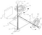
Translated fromKorean도 1은 본 발명의 3차원영상촬영대가 구비된 실험물 촬영장치의 사시도.1 is a perspective view of an experimental photographing apparatus equipped with a three-dimensional image recording table of the present invention.
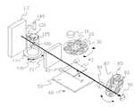
도 2는 본 발명의 실험물 촬영장치의 내부를 보여주기 위한 단면도.Figure 2 is a cross-sectional view for showing the inside of the experimental photographing apparatus of the present invention.
도 3은 본 발명의 실험물 촬영장치의 평면영상을 촬영하는 방법을 도시한 상태도.Figure 3 is a state diagram showing a method for taking a planar image of the experimental photographing apparatus of the present invention.
도 4는 본 발명의 실험물 촬영장치의 광원을 이용하여 3차원영상을 촬영하는 방법을 도시한 상태도.Figure 4 is a state diagram showing a method for photographing a three-dimensional image using a light source of the experimental object photographing apparatus of the present invention.
도 5는 본 발명의 실험물 촬영장치의 레이저스캐너를 이용하여 3차원영상을 촬영하는 방법을 도시한 상태도.5 is a state diagram showing a method of photographing a three-dimensional image using a laser scanner of the experimental photographing apparatus of the present invention.
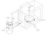
도 6은 본 발명의 실험물 촬영장치의 3차원촬영대에 실험관을 넣는 것을 도시한 상태도.Figure 6 is a state diagram showing the test tube in the three-dimensional imaging table of the experimental object photographing apparatus of the present invention.
<도면의 주요 부분에 대한 부호의 설명><Explanation of symbols for the main parts of the drawings>
10 : 광원 20 : 제1광학필터휠10
25 : 제1광학필터 30 : 제1모터25: first optical filter 30: first motor
40 : 광속분리기 45 : 제2모터40: beam splitter 45: second motor
50 : 제1윈도우 60 : 제1마취가스발생수단50: first window 60: first anesthetic gas generating means
70 : 제2윈도우 80 : 줌광학모듈70: second window 80: zoom optical module
82 : 제2광학필터 85 : 제2광학필터휠82: second optical filter 85: second optical filter wheel
87 : 제4모터 90 : 촬영수단87: fourth motor 90: recording means
95 : 제1도어 99 : 제1외함95: first door 99: first enclosure
100 : 2차원촬영장치 110 : 레이저스캐너100: two-dimensional imaging device 110: laser scanner
120 : 실험관 125 : 고정수단120: test tube 125: fixing means
130 : 제3모터 135 : 실험관설치대130: the third motor 135: experimental tube mounting table
140 : 제2마취가스발생수단 185 : 제2도어140: second anesthetic gas generating means 185: second door
190 : 제2외함 200 : 3차원영상촬영대190: Second enclosure 200: 3D image shooting table
400 : 실험동물400: experimental animal
본 발명은 3차원영상촬영대가 구비된 실험물 촬영장치에 관한 것이다.The present invention relates to an experimental object photographing apparatus equipped with a three-dimensional image photographing table.
실험물 촬영장치란 각종 실험으로 생긴 결과물을 촬영하기 위한 장비이다. 종래에는 2차원의 영상을 촬영하는 장치와 3차원을 촬영하는 장치들을 따로 마련하여 영상을 촬영했었다.Experimental photographing device is a device for photographing the results of various experiments. Conventionally, a device for photographing a two-dimensional image and a device for photographing a three-dimensional image have been separately photographed.
실험물 촬영 장치에 관한 종래 기술로는 샘플에 토션이나 벤딩력을 수십만번까지 반복적으로 가하여 내구성 시험을 하면서 샘플의 파단 장면을 카메라에 의해 자동으로 촬영할 수 있도록 된 촬영 장치에 관하여 공개특허공보 공개번호 제 특1998-044511호(부품 내구시험용 파단장면 촬영 시스템)가 공개되어 있다.Conventional techniques related to an experimental photographing apparatus include a photographing apparatus capable of automatically photographing a fractured scene of a sample by a camera while repeatedly applying a torsion or bending force to a sample up to several hundred thousand times. No. 1998-044511 (A fracture scene photographing system for component durability testing) is disclosed.
그러나, 상기 기술은 부품의 내구성 시험을 촬영하기 위한 것으로 실험물의 2차원영상 또는 3차원영상을 일정한 파장대역에 따른 촬영을 할 수 없는 문제점이 있었다.However, the above technique is to photograph the durability test of the component, there was a problem that can not photograph the two-dimensional image or the three-dimensional image of the specimen according to a certain wavelength band.
본 발명의 3차원영상촬영대가 구비된 실험물 촬영장치는 2차원영상과 3차원영상을 한 장치에서 촬영할 수 있는 실험물 촬영장치를 제공하는 데 목적이 있다.An experimental object photographing apparatus equipped with a 3D image photographing table of the present invention has an object to provide an experimental object photographing apparatus capable of photographing a 2D image and a 3D image in one device.
본 발명은 3차원영상촬영대가 구비된 실험물 촬영장치에 관한 것이다.The present invention relates to an experimental object photographing apparatus equipped with a three-dimensional image photographing table.
본 발명의 3차원영상촬영대가 구비된 실험물 촬영장치는Experimental photographing device equipped with a three-dimensional image recording table of the present invention
2차원촬영장치에 탈부착이 가능한 3차원영상촬영대를 구비하여 시험물의 2차원영상과 3차원영상을 얻을 수 있다.It is possible to obtain a two-dimensional image and a three-dimensional image of the specimen by providing a detachable three-dimensional imaging table in the two-dimensional imaging apparatus.
또한, 3차원영상촬영대는 3차원 영상을 촬영할 때만 결합하면 되므로 설치와 조작이 용이하다.In addition, the three-dimensional image shooting table is easy to install and operate because it only needs to be combined when taking a three-dimensional image.
또, 2차원촬영장치와 3차원촬영장치를 따로 구입할 필요가 없어 경비가 절감 되는 효과가 있다.In addition, there is no need to purchase a two-dimensional imaging device and a three-dimensional imaging device separately, there is an effect of reducing the cost.
본 발명의 3차원영상촬영대가 구비된 실험물 촬영장치는Experimental photographing device equipped with a three-dimensional image recording table of the present invention
실험물이나 실험동물을 촬영하기 위한 빛을 발생하는 광원(10)과;A
상기 광원에서 발생한 빛 중 필요한 파장만을 통과시키는 제1광학필터(25)가 소정의 각도로 설치되어 있는 제1광학필터휠(20)과;A first
상기 제1광학필터휠(20)의 중심에 설치되어 제1광학필터휠(20)을 Z축을 중심으로 회전시키는 제1모터(30)와;A
상기 제1광학필터휠(20)의 아래 설치되어 제1광학필터(25)를 통과한 빛을 일정비율로 통과시키거나 반사시키는 광속분리기(40)와;A
상기 광속분리기(40)의 일측의 밑부분에 설치되고 광속분리기(40)를 X축을 중심으로 회전시키는 제2모터(45)와;A
상기 광속분리기(40)의 아래 설치되고 광속분리기(40)를 통과한 빛을 투과시키는 제1윈도우(50)와;A
상기 광속분리기(40)의 뒷면에 설치되고 광속분리기(40)에서 반사된 빛을 투과시키는 제2윈도우(70)와;A
상기 광속분리기(40)의 앞면에 설치되고, 광속분리기(40)를 통과한 실험물 또는 실험동물(400)의 영상의 크기를 확대하고 축소하는 줌광학모듈(80)과;A zoom optical module (80) installed on the front side of the beam splitter (40) for enlarging and reducing the size of an image of the test object or the experimental animal (400) passing through the beam splitter (40);
상기 줌광학모듈(80)의 앞에 설치되고 실험물 또는 실험동물(400)에서 반사된 빛 중 필요한 파장만을 통과시키는 제2광학필터(82)가 소정의 각도로 설치되어 있는 제2광학필터휠(85)과;A second optical filter wheel installed in front of the zoom
상기 제2광학필터휠(85)의 중심에 설치되어 제2광학필터휠(85)을 Y축을 중심으로 회전시키는 제4모터(87)와;A
상기 줌광학모듈(80)과 제2광학필터휠(85)의 제2광학필터(82)를 통과한 영상을 촬영하는 촬영수단(90)과;Photographing means (90) for photographing an image passing through the second optical filter (82) of the zoom optical module (80) and the second optical filter wheel (85);
상기 광원(10), 제1광학필터휠(20), 제1모터(30), 광속분리기(40), 제2모터(45), 제1윈도우(50), 제2윈도우(70), 줌광학모듈(80), 제2광학필터휠(85), 제4모터(87), 촬영수단(90)이 고정되고 제1윈도우(50)의 아래 설치되어 위아래로 개폐되는 제1도어(95)를 포함하는 제1외함(99)으로 구성된 2차원촬영장치(100)와;The
실험물 또는 실험동물(400)을 투과하는 레이저를 발생시키는 레이저스캐너(110)와;A
상기 레이저스캐너(110)에서 발생된 빛이 투과되고 실험물 또는 실험동물을 고정하는 고정수단(125)이 상부에 설치된 실험관(120)과;A test tube (120) having a fixing means (125) installed thereon for transmitting the light generated by the laser scanner (110) and fixing a test object or an animal;
실험관설치대(135)의 아랫부분에 설치되어 실험관(120)을 Z축을 중심으로 회전시키는 제3모터(130)와;A
상기 제3모터(130)의 위에 고정 설치되고 상기 실험관(120)이 놓여지는 실험관 설치대(135)와;A test
상기 레이저스캐너(110)가 일측에 설치되고, 내부에 실험관(120)과 제3모터(130)가 고정 설치되고, 상기 2차원촬영장치(100)에 설치된 제2윈도우(70)에 탈부착되며 한면을 개폐하는 제2도어(185)를 포함하는 제2외함(190)으로 구성된 3 차원영상촬영대(200)와;The
상기 제1모터(30), 제2모터(45), 줌광학모듈(80), 제4모터(87), 촬영수단(90), 제3모터(130)의 작동을 제어하는 제어부를 포함하여 구성된다.Including a control unit for controlling the operation of the
또한, 상기 제1광학필터휠(20)에 설치되는 제1광학필터(25)와 제2광학필터휠(85)에 설치되는 제2광학필터(82)는 60°간격으로 설치되고 2개는 교환이 가능한 것을 특징으로 한다.In addition, the first
또한, 상기 2차원촬영장치(100)는 상기 제1윈도우(50)의 아래 설치되고 생물을 마취시키는 가스가 발생하는 제1마취가스발생수단(60)이 더 구비되는 것을 특징으로 한다.In addition, the two-
또한, 상기 3차원영상촬영대(200)는 제2외함(190)의 상부 내부에 설치되고 생물을 마취시키는 가스가 발생하는 제2마취가스발생수단(140)이 더 구비되는 것을 특징으로 한다.In addition, the three-dimensional image shooting table 200 is characterized in that the second anesthetic gas generating means 140 is further provided in the upper inside of the
또한, 상기 2차원촬영장치(100)로 실험물(400) 또는 실험동물(400)이 촬영될 때는 제2모터(45)에 의해서 광속분리기(45)가 X축을 중심으로 45°기울어지는 것을 특징으로 한다.In addition, when the
또한, 상기 2차원촬영장치(100)와 3차원영상촬영대(200)를 결합하여 실험관(120)안에 고정된 실험물 또는 실험동물(400)이 광원(10)에 의해서 촬영될 때는 제2모터(45)에 의해서 광속분리기(45)가 X축을 중심으로 45°기울어지고 제3모터(130)에 의해서 실험관(120)이 놓여진 실험관설치대(135)가 Z축을 중심으로 소정의 각도로 회전하는 것을 특징으로 한다.In addition, the second motor is coupled to the two-
또한, 상기 2차원촬영장치(100)와 3차원영상촬영대(200)를 결합하여 실험관(120)안에 고정된 실험물 또는 실험동물(400)이 레이저스캐너(110)에 의해서 촬영될 때는 제2모터(45)에 의해서 광속분리기(45)가 X축을 중심으로 0°기울어지고 제3모터(130)에 의해서 실험관(120)이 놓여진 실험관설치대(135)가 Z축을 중심으로 소정의 각도로 회전하는 것을 특징으로 한다.In addition, when the test object or the
도면을 참조로 본 발명의 3차원영상촬영대가 구비된 실험물 촬영장치에 대하여 설명한다.Referring to the drawings will be described with respect to the experimental object photographing apparatus equipped with a three-dimensional image recording table of the present invention.
그러나, 도면에 의해서 본 발명의 기술적 사상이 한정되는 것은 아니다.However, the technical idea of the present invention is not limited by the drawings.
도 1은 본 발명의 3차원영상촬영대가 구비된 실험물 촬영장치의 사시도이고,1 is a perspective view of an experimental photographing apparatus equipped with a three-dimensional image recording table of the present invention,
도 2는 내부를 보이기 위해 한면을 자른 단면도이다.Figure 2 is a cross-sectional view cut one side to show the inside.
본 발명의 3차원영상촬영대가 구비된 실험물 촬영장치는 2차원촬영장치(100)와 3차원영상촬영대(200), 그리고 제어부로 구성된다.The experimental object photographing apparatus equipped with the 3D image photographing table of the present invention includes a
본 발명의 실험물 촬영장치의 2차원촬영장치(100)에 대해서 설명한다.The two-dimensional photographing
본 발명의 실험물 촬영장치에서 2차원촬영장치(100)는In the experimental photographing apparatus of the present invention, the two-dimensional photographing
실험물이나 실험동물을 촬영하기 위한 빛을 발생하는 광원(10)과;A
상기 광원에서 발생한 빛 중 필요한 파장만을 통과시키는 제1광학필터(25)가 소정의 각도로 설치되어 있는 제1광학필터휠(20)과;A first
상기 제1광학필터휠(20)의 중심에 설치되어 제1광학필터휠(20)을 Z축을 중심으로 회전시키는 제1모터(30)와;A
상기 제1광학필터휠(20)의 아래 설치되어 제1광학필터(25)를 통과한 빛을 일정비율로 통과시키거나 반사시키는 광속분리기(40)와;A
상기 광속분리기(40)의 일측의 밑부분에 설치되고 광속분리기(40)를 X축을 중심으로 회전시키는 제2모터(45)와;A
상기 광속분리기(40)의 아래 설치되고 광속분리기(40)를 통과한 빛을 투과시키는 제1윈도우(50)와;A
상기 광속분리기(40)의 뒷면에 설치되고 광속분리기(40)에서 반사된 빛을 투과시키는 제2윈도우(70)와;A
상기 광속분리기(40)의 앞면에 설치되고, 광속분리기(40)를 통과한 실험물 또는 실험동물의 영상의 크기를 확대하고 축소하는 줌광학모듈(80)과;A zoom optical module (80) installed on the front side of the beam splitter (40) for enlarging and reducing the size of an image of a test object or an experiment animal passing through the beam splitter (40);
상기 줌광학모듈(80)의 앞에 설치되고 실험물 또는 실험동물(400)에서 반사된 빛 중 필요한 파장만을 통과시키는 제2광학필터(82)가 소정의 각도로 설치되어 있는 제2광학필터휠(85)과;A second optical filter wheel installed in front of the zoom
상기 제2광학필터휠(85)의 중심에 설치되어 제2광학필터휠(85)을 Y축을 중심 으로 회전시키는 제4모터(87)와;A
상기 줌광학모듈(80)과 제2광학필터휠(85)의 제2광학필터(82)를 통과한 영상을 촬영하는 촬영수단(90)과;Photographing means (90) for photographing an image passing through the second optical filter (82) of the zoom optical module (80) and the second optical filter wheel (85);
상기 광원(10), 제1광학필터휠(20), 제1모터(30), 광속분리기(40), 제2모터(45), 제1윈도우(50), 제2윈도우(70), 줌광학모듈(80), 제2광학필터휠(85), 제4모터(87), 촬영수단(90)이 고정되고 제1윈도우(50)의 아래 설치되어 위아래로 개폐되는 제1도어(95)를 포함하는 제1외함(99)으로 구성된다.The
도 1, 도 2, 도3을 참조로 본 발명의 실험물 촬영장치의 2차원촬영장치(200)에 대하여 상세히 설명한다.1, 2, and 3 will be described in detail with respect to the two-
광원(10)은 실험물이나 실험동물을 촬영하기 위한 빛을 발생하는 구성요소로 통상의 전기에 의해서 빛을 발생하는 전구나 고휘도의 LED등 빛을 발생할 수 있는 것들이면 대체 가능하다. 또한, 광원(10)은 2차원촬영장치(200)의 위쪽에 설치되어 아래쪽으로 빛이 발산되도록 설치된다. 광원(10)에 의해서 발생된 빛은 제1광학필터(25)를 통과하여 필요한 파장의 빛만을 통과시키고 광속분리기(40)를 통과하거나 반사되면서 실험물 또는 실험동물(400)을 비추게 된다.The
제1광학필터휠(20)은 상기 광원에서 발생한 빛 중 필요한 파장만을 통과시키는 제1광학필터(25)가 소정의 각도로 설치되어 있다. 제1광학필터휠(20)에 설치되는 제1광학필터(25)는 여러개를 설치할 수 있는데 가장 효과적인 개수는 60도의 간 격으로 설치된 6개이다. 여러개중 일부는 고정시키고 일부는 탈부착이 가능하도록 할 수 있다. 사용의 편의를 위하여 6개의 제1광학필터(25)를 설치하였을 때 4개는 고정시키고 2개는 탈부착이 가능하도록 한다. 또한, 제1광학필터휠(20)의 제1광학필터(25)는 실험동물(400)의 실험결과를 촬영하기 위하여 400nm 에서 900nm의 파장을 통과시킬 수 있는 것들로 선택한다. 제1광학필터휠(20)은 합성수지 또는 금속등 변형이 일어나지 않는 재질이면 다른 것을 사용하여 만들수도 있다.The first
제1모터(30)는 상기 제1광학필터휠(20)의 중심에 설치되어 제1광학필터휠(20)을 Z축을 중심으로 회전시킨다. 제1모터(30)는 제1광학필터휠(20)에 설치된 여러종류의 제1광학필터(25)를 사용할 수 있도록 하기 위한 것이다. 도 2에서 제1모터(30)는 제1광학필터휠(20)의 중심부에 설치되어 회전하도록 한다. 제1모터(30)는 정확한 각도 제어를 위하여 스테핑모터나 서보모터가 이용된다. 또한, 제1모터(30)는 제어부와 연결되어 제어부의 제어신호에 의해서 제어된다.The
광속분리기(40)는 상기 제1광학필터휠(20)의 아래 설치되어 제1광학필터(25)를 통과한 빛을 일정비율로 통과시키거나 반사시킨다. 광속분리기(40)는 빛의 일부는 통과 시키고 일부는 반사시키는 것으로 2차원영상촬영장치(100)는 광원(10)에서 발생된 빛이 제1광학필터(25)를 통과하고 광속분리기(40)를 통과한 빛은 아래 설치된 실험동물(400)에 비추어지고 실험동물(400)에서 반사된 빛은 다시 광속분리기(40)를 통하여 반사되어 제2광학필터(82)를 통하여 촬영되게 된다.The
제2모터(45)는 상기 광속분리기(40)의 일측의 밑부분에 설치되고 광속분리기(40)를 X축을 중심으로 회전시킨다. 제2모터(45)는 광속분리기(40)의 각도를 조정하기 위한 것이다. 레이저스캐너(110)을 이용하여 3차원영상을 촬영할 때 광속분리기(40)의 각도는 0°이고 그외의 경우에는 45°의 각도를 유지하여야 한다. 제2모터(45)는 상술한 바와 같이 필요한 상황에 맞게 광속분리기(40)의 각도를 조정하는데 사용한다. 제2모터(45)는 일정한 각도를 조정할 수 있어야 하므로 서보모터나 스태핑모터로 구성된다. 또한, 제1모터(30)는 제어부와 연결되어 제어부의 제어신호에 의해서 제어된다.The
제1윈도우(50)는 상기 광속분리기(40)의 아래 설치되고 광속분리기(40)를 통과한 빛을 투과시킨다. 제1윈도우(50)는 실험물이나 실험동물(400)을 놓는 자리의 위 즉 광속분리기(40)의 아래에 설치되어 시험물이나 시험동물(400)과 장치를 분리시켜주는 역할을 한다. 제1윈도우(50)는 빛이 투과되는 투명한 재질로 만들어 진다.The
제2윈도우(70)는 상기 광속분리기(40)의 뒷면에 설치되고 광속분리기(40)에서 반사된 빛을 투과시킨다. 제2윈도우(70)는 상기 제1윈도우(50)와 같이 실험물 이나 실험동물(400)을 장치와 분리시켜 주는 역할을 하며 실험물이나 실험동물(400)의 3차원영상을 촬영하기 위하여 사용된다.The
줌광학모듈(80)은 상기 광속분리기(40)의 앞면에 설치되고, 광속분리기(40)을 통과한 실험물 또는 실험동물의 영상의 크기를 확대하고 축소한다. 줌광학모듈(80)은 카메라에서 확대및 축소를 하는 부분으로 촬영하기 위한 실험물이나 실험동물의 영상을 자세하게 촬영하기 위한 것이다. 줌광학모듈(80)은 제어부와 연결되어 제어부의 제어신호에 의해서 영상을 확대하고 축소한다.The zoom
제2광학필터휠(85)은 상기 줌광학모듈(80)의 앞에 설치되고 실험물 또는 실험동물(400)에서 반사된 빛 중 필요한 파장만을 통과시키는 제2광학필터(82)가 소정의 각도로 설치된다. 6개의 제2광학필터(82)를 설치할 때는 60°의 간격으로 설치하고 2개는 교환이 가능하도록 한다. 제2광학필터휠(85)은 실험물 또는 실험동물(400)에서 반사된 빛에서 필요한 파장대역의 영상을 얻기 위해 사용된다. 제2광학필터휠(85)에 설치되는 제2광학필터(82)은 400nm 에서 900nm의 파장을 통과시킬 수 있는 것들로 선택한다. 제2광학필터휠(85)은 합성수지 또는 금속등 변형이 일어나지 않는 재질이면 다른 것을 사용하여 만들수도 있다.The second
제2광학필터휠(85)은 중심이 제4모터(87)에 연결되어 회전된다.The second
제4모터(87)는 상기 제2광학필터휠(85)의 중심에 설치되어 제2광학필터휠(85)을 Y축을 중심으로 회전시킨다. 제4모터(87)는 제2광학필터휠(85)을 소정의 각도로 회전시키기 위하여 서보모터나 스태핑모터로 구성된다. 제4모터(87)는 제어부 와 연결되어 제어부의 제어신호에 의해서 제어된다.The
촬영수단(90)은 상기 줌광학모듈(80)과 제2광학필터휠(85)의 제2광학필터(82)를 통과한 영상을 촬영한다. 촬영수단(90)은 실험물이나 실험동물(400)의 영상을 촬영하는 것으로 CCD나 CMOS형 이미지센서로 구성된다. 촬영된 이미지는 디지털화되어 다른 기기로 전송되어 사용되어진다.The photographing means 90 captures an image passing through the zoom
제1외함(99)은 상기 광원(10), 제1광학필터휠(20), 제1모터(30), 광속분리기(40), 제2모터(45), 제1윈도우(50), 제2윈도우(70), 줌광학모듈(80), 제2광학필터휠(85), 제4모터(87), 촬영수단(90)이 고정되고 제1윈도우(50)의 아래 설치되어 위아래로 개폐되는 제1도어(95)를 포함하여 구성된다. 제1외함(99)은 2차원촬영장치(100)의 외형을 이루는 것으로 합성수지나 금속등 모양을 갖출 수 있는 것이면 가능하다. 제1외함(99)의 제1도어(95)는 실험물이나 실험동물(400)이 놓여 지는 제1윈도우(50)의 아래부분을 개폐하기 위한 것으로 제1외함(99)의 측면 아래 부분에 제1윈도우(50)에서 외함(99)의 아래부분을 막을 수 있는 크기로 만들진다. 제1도어(95)는 사용상 편의를 위하여 위아래로 개폐되도록 설치된다.The
또한, 상기 2차원촬영장치(100)는 상기 제1윈도우(50)의 아래 설치되어 생물을 마취시키는 가스가 발생하는 제1마취가스발생수단(60)이 더 구비할 수도 있다. 제1마취가스발생수단(60)은 마취액일 담긴 용기의 형태일 수도 있고 마취액을 분사할 수 있는 분사기의 형태일 수도 있다. In addition, the two-
도 1, 도2, 도 4, 도 5를 참조로 3차원영상촬영대(200)에 대하여 상세히 설명한다.1, 2, 4 and 5 will be described in detail with respect to the three-dimensional image shooting table 200.
레이저스캐너(110)는 실험물 또는 실험동물을 투과하는 레이저를 발생시킨다. 레이저스캐너(110)에 발생하는 레이저는 실험물 또는 실험동물(400)을 투과하는 성질이 있으므로 실험물 또는 실험동물(400)의 내부를 촬영하는데 사용된다. 레이져스캐너(100)는 실험관(120)속에 고정되어 있는 실험물 또는 실험동물(400)의 내부에 비춰질수 있도록 실험물 또는 실험동물(400)의 뒤에 설치된다.The
실험관(120)은 상기 레이저스캐너(110)에서 발생된 빛이 투과되고 실험물 또는 실험동물을 고정하는 고정수단(125)이 상부에 설치된다. 실험관(120)은 실험물또는 실험동물(400)을 외부와 차단하고 고정시키기 위하여 설치되는 것으로 레이저나 빛이 투과될 수 있는 투명한 재질로 만들어진다. 도 4와 도 5는 실험관(120)속에 실험동물(400)이 고정되어 있는 것이 도시되어 있다. 실험관의 상단에 설치되는 고정수단(125)은 실험물이나 실험동물(400)을 고정하기 위한 것으로 집게나 클립같이 고정할 수 있는 것이면 대체 가능하다. 실험관(120)은 실험관설치대(135)위에 놓여진다. 실험관(120)은 실험관설치대(135)에 놓여져 제3모터(130)와 같이 회전하게 된다.The
제3모터(130)는 실험관설치대(135)의 아랫부분에 설치되어 실험관설치대(135)를 Z축을 중심으로 회전시킨다. 제3모터(130)는 실험관설치대(135)를 회전시켜 위에 놓여진 실험관(120)속의 실험물이나 실험동물(400)의 3차원영상을 만들기 위한 것으로 소정의 각도로 회전할 수 있는 서보모터 또는 스테핑모터로 구성된다. 또한, 제어부와 연결되어 제어부의 신호에 의해서 제어된다.The
실험관설치대(135)는 상기 제3모터(130)의 위에 고정 설치되고 상기 실험관(120)이 놓여진다. 실험관설치대(135)는 제3모터(130)의 회전력을 실험관(120)에 전달하기 위한 것이다. 실험관(120)에 실험물 또는 실험동물(400)을 넣고 빼는 작업을 용이하게 하기 위하여 설치한다. 실험관(120)을 안정적으로 놓을 수 있는 모양이면 다양하게 변환할 수 있다.The test
제2외함(190)은 상기 레이저스캐너(110)가 일측에 설치되고, 내부에 실험관설치대(135)와 제3모터(130)가 고정 설치되고, 상기 2차원촬영장치(100)에 설치된 제2윈도우(70)에 탈부착되며 한면을 개폐하는 제2도어(185)를 포함한다.The
제2외함(190)은 3차원영상촬영대(200)의 외형을 구성하고 2차원촬영장치(100)와 결합되는 역할을 한다. 또한, 실험관(120)을 넣고 빼기 위한 제2도어(185)가 측면에 설치되어 있다. The
또한, 상기 3차원촬영장치(200)는 제2외함(190)의 상부 내부에 설치되고 생 물을 마취시키는 가스가 발생하는 제2마취가스발생수단(140)이 더 구비될 수 있다.In addition, the three-
제2마취가스발생수단(140)은 마취액이 담긴 용기의 형태일 수도 있고 마취액을 분사할 수 있는 분사기의 형태일 수도 있다. 실험동물(400)의 영상을 촬영하는 중 실험동물(400)이 깨어나는 것을 방지하기 위해 사용된다.The second anesthetic gas generating means 140 may be in the form of a container containing the anesthetic liquid or may be in the form of an injector capable of injecting anesthetic liquid. It is used to prevent the
도 6은 3차원영상촬영대(200)에 실험관(120)을 넣고 빼는 것을 도시한 것이다.6 illustrates the insertion and withdrawal of the
제어부는 상기한 제1모터(30), 제2모터(45), 제4모터(87), 줌광학모듈(80), 촬영수단(90), 제3모터(130)의 작동을 제어하기 위한 것으로 마이크로콘트롤러, 씨피유(CPU), 피엘씨(PLC), 컴퓨터등이 될 수 있다.The control unit controls the operation of the
도 3를 참조로 상기한 2차원촬영장치(100)에 의해서 실험동물의 평면영상이 찍히는 작용에 대하여 설명한다.The operation of taking a planar image of the experimental animal by the two-
2차원영상을 촬영하기 위해서는 우선 도 3와같이 광속분리기가 45°의 각도로 기울어진다. 이때 찍고자 하는 파장의 제1광학필터(25)가 광원(10)의 밑으로 가도록 제1모터가 회전된다. 이후 광원(10)에서 빛이 발생하고 실험물이나 실험동물(400)이 비춰져 광속분리기(40)에 반사된 영상을 줌광학모듈(80)을 거쳐 제4모터(87)의 회전으로 선택된 제2광학필터(82)를 거쳐 촬영수단(90)에 의해서 촬영된다. 화살표는 광원(10)에서 발생된 빛의 경로를 표시한 것이다.In order to take a two-dimensional image, the beam splitter is inclined at an angle of 45 ° as shown in FIG. 3. At this time, the first motor is rotated such that the first
도 4 와 도 5를 참조로 상기한 2차원촬영장치(100)에 3차원영상촬영대(200)를 결합하여 3차원영상을 촬영하는 작용에 대하여 설명한다.4 and 5 will be described the operation of taking a three-dimensional image by combining the three-dimensional imaging table 200 with the two-
도 4는 광원(10)에서 발생한 빛을 이용하여 3차원영상이 촬영되는 것을 도시한 것이다.4 illustrates that a 3D image is captured by using light generated by the
우선 광속분리기가 45°의 각도로 기울어진다. 이때 찍고자 하는 파장의 제1광학필터(25)가 광원(10)의 밑으로 가도록 제1모터(30)가 회전된다. 광원(10)에서 빛이 발생하고 발생된 빛은 광속분리기(40)에 반사되어 제2윈도우(70)를 통과한 후 실험관(120)안에 고정된 실험물 또는 실험동물(400)에게 반사되어 줌광학모듈(80)을 거쳐 제4모터(87)의 회전으로 선택된 제2광학필터(82)를 통과하여 촬영수단(90)에 의해서 영상이 촬영된다. 이때 제3모터(130)가 소정의 간격(예를 들면 1°간격)으로 회전하며 연속으로 찍힌 영상들을 편집하여 3차원의 영상을 만든다. 화살표는 광원(10)에서 발생된 빛의 경로를 표시한 것이다.First, the beam splitter is tilted at an angle of 45 °. At this time, the
도 5는 레이저스캐너(110)에서 발생한 레이저를 이용하여 3차원영상이 촬영되는 것을 도시한 것이다.FIG. 5 illustrates that a 3D image is captured by using a laser generated by the
우선 광속분리기가 0°의 각도로 기울어진다. 레이저스캐너(110)에서 레이저가 발생하고 실험관(120)에 고정된 실험물 또는 실험동물(400)을 투과하여 제2윈도우(70)를 통해 줌광학모듈(80)로 전송되고 제4모터(87)의 회전으로 선택된 제2광학필터(82)를 통과하여 촬영수단(90)에 의해서 레이저에 의해서 투과된 영상이 촬영된다. 이때도 광원(10)을 이용하여 3차원영상을 촬영했던 것과 마찬가지로 제3모터 (130)가 소정의 각도(예를 들면 1°)로 회전하며 연속으로 찍힌 영상들을 저장하고 편집하여 3차원영상을 만든다.First, the beam splitter is tilted at an angle of 0 °. The laser is generated in the
본 발명의 3차원영상촬영대가 구비된 실험물 촬영장치는 2차원촬영장치에 탈부착이 가능한 3차원영상촬영대를 구비하여 시험물의 2차원영상과 3차원영상을 얻을 수 있다.The experimental object photographing apparatus equipped with the three-dimensional image photographing table of the present invention includes a three-dimensional image photographing table detachable to the two-dimensional photographing apparatus to obtain a two-dimensional image and a three-dimensional image of the test object.
또한, 3차원영상촬영대는 3차원 영상을 촬영할 때만 결합하면 되므로 설치와 조작이 용이하다.In addition, the three-dimensional image shooting table is easy to install and operate because it only needs to be combined when taking a three-dimensional image.
또, 2차원촬영장치와 3차원촬영장치를 따로 구입할 필요가 없어 경비가 절감되는 효과가 있다.In addition, there is no need to purchase a two-dimensional imaging apparatus and a three-dimensional imaging apparatus separately, there is an effect that the cost is reduced.
Claims (7)
Translated fromKoreanPriority Applications (3)
| Application Number | Priority Date | Filing Date | Title |
|---|---|---|---|
| KR1020050121579AKR100660519B1 (en) | 2005-12-12 | 2005-12-12 | Experimental photographing device equipped with a 3D imaging platform |
| US12/096,003US7747163B2 (en) | 2005-12-12 | 2006-12-11 | Testing matter photographing apparatus attached three dimensional image photographing device |
| PCT/KR2006/005388WO2007069840A1 (en) | 2005-12-12 | 2006-12-11 | The testing matter photographing apparatus attached three dimensional image photographing device |
Applications Claiming Priority (1)
| Application Number | Priority Date | Filing Date | Title |
|---|---|---|---|
| KR1020050121579AKR100660519B1 (en) | 2005-12-12 | 2005-12-12 | Experimental photographing device equipped with a 3D imaging platform |
Publications (1)
| Publication Number | Publication Date |
|---|---|
| KR100660519B1true KR100660519B1 (en) | 2006-12-22 |
Family
ID=37815282
Family Applications (1)
| Application Number | Title | Priority Date | Filing Date |
|---|---|---|---|
| KR1020050121579AExpired - Fee RelatedKR100660519B1 (en) | 2005-12-12 | 2005-12-12 | Experimental photographing device equipped with a 3D imaging platform |
Country Status (3)
| Country | Link |
|---|---|
| US (1) | US7747163B2 (en) |
| KR (1) | KR100660519B1 (en) |
| WO (1) | WO2007069840A1 (en) |
Cited By (4)
| Publication number | Priority date | Publication date | Assignee | Title |
|---|---|---|---|---|
| KR101798215B1 (en)* | 2016-10-14 | 2017-11-15 | 넷코덱(주) | System and Method for Acquiring and Analizing 3D Fluorescent Image |
| CN113376171A (en)* | 2021-06-25 | 2021-09-10 | 政禾科技(杭州)有限公司 | Intelligent electric control experimental device |
| KR20220045715A (en)* | 2020-10-06 | 2022-04-13 | 서울대학교산학협력단 | Filter-based imaging system for monitoring plant function |
| KR20220095814A (en) | 2020-12-30 | 2022-07-07 | 단국대학교 천안캠퍼스 산학협력단 | Light irradiation fixing apparatus for small animals |
Families Citing this family (12)
| Publication number | Priority date | Publication date | Assignee | Title |
|---|---|---|---|---|
| US9164037B2 (en) | 2007-01-26 | 2015-10-20 | Palo Alto Research Center Incorporated | Method and system for evaluation of signals received from spatially modulated excitation and emission to accurately determine particle positions and distances |
| US8821799B2 (en) | 2007-01-26 | 2014-09-02 | Palo Alto Research Center Incorporated | Method and system implementing spatially modulated excitation or emission for particle characterization with enhanced sensitivity |
| US7817254B2 (en)* | 2008-01-30 | 2010-10-19 | Palo Alto Research Center Incorporated | Obtaining information from time variation of sensing results |
| EP2085762B1 (en)* | 2008-01-30 | 2018-07-04 | Palo Alto Research Center Incorporated | Transmitting/reflecting emanating light with time variation |
| EP2085797B1 (en)* | 2008-01-30 | 2016-06-01 | Palo Alto Research Center Incorporated | Producing Filters with Combined Transmission and/or Reflection Functions |
| US8373860B2 (en) | 2008-02-01 | 2013-02-12 | Palo Alto Research Center Incorporated | Transmitting/reflecting emanating light with time variation |
| US8629981B2 (en) | 2008-02-01 | 2014-01-14 | Palo Alto Research Center Incorporated | Analyzers with time variation based on color-coded spatial modulation |
| US8319823B2 (en)* | 2009-11-03 | 2012-11-27 | Jadak, Llc | System and method for panoramic image stitching |
| CN102918355B (en)* | 2011-04-22 | 2017-05-31 | 松下知识产权经营株式会社 | Three-dimensional camera device, image processing device |
| US9029800B2 (en) | 2011-08-09 | 2015-05-12 | Palo Alto Research Center Incorporated | Compact analyzer with spatial modulation and multiple intensity modulated excitation sources |
| US8723140B2 (en) | 2011-08-09 | 2014-05-13 | Palo Alto Research Center Incorporated | Particle analyzer with spatial modulation and long lifetime bioprobes |
| US9494805B2 (en) | 2013-03-26 | 2016-11-15 | Lightspeed Design, Inc. | Stereoscopic light recycling device |
Citations (5)
| Publication number | Priority date | Publication date | Assignee | Title |
|---|---|---|---|---|
| JPH06186035A (en)* | 1992-12-16 | 1994-07-08 | Taisei Corp | Three-dimenisonal position measuring system |
| KR200214661Y1 (en) | 2000-08-10 | 2001-02-15 | 김학균 | Apparatus for fixing a subject for photography and a camera taking a 3 dimensional images |
| JP2001280933A (en) | 2000-03-31 | 2001-10-10 | Minolta Co Ltd | Photographing system, and two-dimensional image pick-up device and three-dimensional measuring instrument used for the system |
| KR20030016452A (en)* | 2001-08-16 | 2003-03-03 | 다본정보기술 주식회사 | Three-dimension photography apparatus |
| JP2004240138A (en) | 2003-02-05 | 2004-08-26 | I-O Data Device Inc | Camera for multieye stereoscopic vision |
Family Cites Families (5)
| Publication number | Priority date | Publication date | Assignee | Title |
|---|---|---|---|---|
| KR19980044511A (en) | 1996-12-06 | 1998-09-05 | 박병재 | Fracture Scene Shooting System for Component Durability Testing |
| US6406845B1 (en)* | 1997-05-05 | 2002-06-18 | Trustees Of Tuft College | Fiber optic biosensor for selectively detecting oligonucleotide species in a mixed fluid sample |
| WO2000006990A2 (en)* | 1998-07-27 | 2000-02-10 | Ljl Biosystems, Inc. | Apparatus and methods for time-resolved spectroscopic measurements |
| US7298415B2 (en)* | 2001-07-13 | 2007-11-20 | Xenogen Corporation | Structured light imaging apparatus |
| US7599731B2 (en)* | 2002-07-16 | 2009-10-06 | Xenogen Corporation | Fluorescent light tomography |
- 2005
- 2005-12-12KRKR1020050121579Apatent/KR100660519B1/ennot_activeExpired - Fee Related
- 2006
- 2006-12-11WOPCT/KR2006/005388patent/WO2007069840A1/enactiveApplication Filing
- 2006-12-11USUS12/096,003patent/US7747163B2/ennot_activeExpired - Fee Related
Patent Citations (5)
| Publication number | Priority date | Publication date | Assignee | Title |
|---|---|---|---|---|
| JPH06186035A (en)* | 1992-12-16 | 1994-07-08 | Taisei Corp | Three-dimenisonal position measuring system |
| JP2001280933A (en) | 2000-03-31 | 2001-10-10 | Minolta Co Ltd | Photographing system, and two-dimensional image pick-up device and three-dimensional measuring instrument used for the system |
| KR200214661Y1 (en) | 2000-08-10 | 2001-02-15 | 김학균 | Apparatus for fixing a subject for photography and a camera taking a 3 dimensional images |
| KR20030016452A (en)* | 2001-08-16 | 2003-03-03 | 다본정보기술 주식회사 | Three-dimension photography apparatus |
| JP2004240138A (en) | 2003-02-05 | 2004-08-26 | I-O Data Device Inc | Camera for multieye stereoscopic vision |
Cited By (5)
| Publication number | Priority date | Publication date | Assignee | Title |
|---|---|---|---|---|
| KR101798215B1 (en)* | 2016-10-14 | 2017-11-15 | 넷코덱(주) | System and Method for Acquiring and Analizing 3D Fluorescent Image |
| KR20220045715A (en)* | 2020-10-06 | 2022-04-13 | 서울대학교산학협력단 | Filter-based imaging system for monitoring plant function |
| KR102428068B1 (en)* | 2020-10-06 | 2022-08-01 | 서울대학교산학협력단 | Filter-based imaging system for monitoring plant function |
| KR20220095814A (en) | 2020-12-30 | 2022-07-07 | 단국대학교 천안캠퍼스 산학협력단 | Light irradiation fixing apparatus for small animals |
| CN113376171A (en)* | 2021-06-25 | 2021-09-10 | 政禾科技(杭州)有限公司 | Intelligent electric control experimental device |
Also Published As
| Publication number | Publication date |
|---|---|
| US20090041449A1 (en) | 2009-02-12 |
| US7747163B2 (en) | 2010-06-29 |
| WO2007069840A1 (en) | 2007-06-21 |
Similar Documents
| Publication | Publication Date | Title |
|---|---|---|
| KR100660519B1 (en) | Experimental photographing device equipped with a 3D imaging platform | |
| US20020196438A1 (en) | Color analyzing apparatus with polarized light source | |
| US6987531B2 (en) | Imaging system, photographing device and three-dimensional measurement auxiliary unit used for the system | |
| DK2786696T3 (en) | DENTAL CAMERA SYSTEM | |
| JP2008295084A (en) | Electronic camera for microscope | |
| JP2005157328A (en) | Microscope camera | |
| KR101473768B1 (en) | Apparatus for the generation of diffuse and specular images based on a polarized light field camera and control method thereof | |
| JP2014115151A (en) | Optical imaging device | |
| JP2004029792A (en) | Imaging apparatus having automatic medium identification function, camera for electronically recording image to film, and method of automatically identifying medium in imaging apparatus | |
| US7603031B1 (en) | Programmable, multi-spectral, image-capture environment | |
| JP2018044997A (en) | Microscope device, microscope system, and imaging method | |
| JPH1173491A5 (en) | ||
| JP2009031091A (en) | Device for measuring rotary body | |
| KR102648059B1 (en) | Mobile otoscope system | |
| CN119863375A (en) | Data acquisition system for infrared image separation and method using same | |
| JP2003348418A (en) | Electronic magnifier | |
| JP2010046309A (en) | Evaluation method and evaluation device of dullness of skin | |
| US7925331B2 (en) | Apparatus for displaying a tissue containing a fluorescent dye | |
| JP2017083523A (en) | Photographing device, photographing method, and meat quality evaluation method for carcass | |
| CA2388286C (en) | Color analyzing apparatus with polarized light source | |
| CN208334865U (en) | A kind of magnifying viewer | |
| RU2050543C1 (en) | Device for recording images of complicate profile surface located at a given depth in an object | |
| JP6617978B2 (en) | Optical imaging device | |
| de Jong et al. | Brandaris 128: a rotating mirror digital camera with 128 frames at 25 Mfps | |
| JPH0715523Y2 (en) | Fingerprint capture device |
Legal Events
| Date | Code | Title | Description |
|---|---|---|---|
| A201 | Request for examination | ||
| PA0109 | Patent application | St.27 status event code:A-0-1-A10-A12-nap-PA0109 | |
| PA0201 | Request for examination | St.27 status event code:A-1-2-D10-D11-exm-PA0201 | |
| D13-X000 | Search requested | St.27 status event code:A-1-2-D10-D13-srh-X000 | |
| D14-X000 | Search report completed | St.27 status event code:A-1-2-D10-D14-srh-X000 | |
| E701 | Decision to grant or registration of patent right | ||
| PE0701 | Decision of registration | St.27 status event code:A-1-2-D10-D22-exm-PE0701 | |
| R18-X000 | Changes to party contact information recorded | St.27 status event code:A-3-3-R10-R18-oth-X000 | |
| GRNT | Written decision to grant | ||
| PR0701 | Registration of establishment | St.27 status event code:A-2-4-F10-F11-exm-PR0701 | |
| PR1002 | Payment of registration fee | St.27 status event code:A-2-2-U10-U11-oth-PR1002 Fee payment year number:1 | |
| PG1601 | Publication of registration | St.27 status event code:A-4-4-Q10-Q13-nap-PG1601 | |
| PR1001 | Payment of annual fee | St.27 status event code:A-4-4-U10-U11-oth-PR1001 Fee payment year number:4 | |
| PR1001 | Payment of annual fee | St.27 status event code:A-4-4-U10-U11-oth-PR1001 Fee payment year number:5 | |
| PR1001 | Payment of annual fee | St.27 status event code:A-4-4-U10-U11-oth-PR1001 Fee payment year number:6 | |
| FPAY | Annual fee payment | Payment date:20121213 Year of fee payment:7 | |
| PR1001 | Payment of annual fee | St.27 status event code:A-4-4-U10-U11-oth-PR1001 Fee payment year number:7 | |
| R18-X000 | Changes to party contact information recorded | St.27 status event code:A-5-5-R10-R18-oth-X000 | |
| FPAY | Annual fee payment | Payment date:20131213 Year of fee payment:8 | |
| PR1001 | Payment of annual fee | St.27 status event code:A-4-4-U10-U11-oth-PR1001 Fee payment year number:8 | |
| FPAY | Annual fee payment | Payment date:20141114 Year of fee payment:9 | |
| PR1001 | Payment of annual fee | St.27 status event code:A-4-4-U10-U11-oth-PR1001 Fee payment year number:9 | |
| FPAY | Annual fee payment | Payment date:20151211 Year of fee payment:10 | |
| PR1001 | Payment of annual fee | St.27 status event code:A-4-4-U10-U11-oth-PR1001 Fee payment year number:10 | |
| PR1001 | Payment of annual fee | St.27 status event code:A-4-4-U10-U11-oth-PR1001 Fee payment year number:11 | |
| R18-X000 | Changes to party contact information recorded | St.27 status event code:A-5-5-R10-R18-oth-X000 | |
| PR1001 | Payment of annual fee | St.27 status event code:A-4-4-U10-U11-oth-PR1001 Fee payment year number:12 | |
| FPAY | Annual fee payment | Payment date:20181217 Year of fee payment:13 | |
| PR1001 | Payment of annual fee | St.27 status event code:A-4-4-U10-U11-oth-PR1001 Fee payment year number:13 | |
| FPAY | Annual fee payment | Payment date:20200203 Year of fee payment:14 | |
| PR1001 | Payment of annual fee | St.27 status event code:A-4-4-U10-U11-oth-PR1001 Fee payment year number:14 | |
| R18-X000 | Changes to party contact information recorded | St.27 status event code:A-5-5-R10-R18-oth-X000 | |
| PR1001 | Payment of annual fee | St.27 status event code:A-4-4-U10-U11-oth-PR1001 Fee payment year number:15 | |
| PN2301 | Change of applicant | St.27 status event code:A-5-5-R10-R13-asn-PN2301 St.27 status event code:A-5-5-R10-R11-asn-PN2301 | |
| PR1001 | Payment of annual fee | St.27 status event code:A-4-4-U10-U11-oth-PR1001 Fee payment year number:16 | |
| PR1001 | Payment of annual fee | St.27 status event code:A-4-4-U10-U11-oth-PR1001 Fee payment year number:17 | |
| PC1903 | Unpaid annual fee | St.27 status event code:A-4-4-U10-U13-oth-PC1903 Not in force date:20231216 Payment event data comment text:Termination Category : DEFAULT_OF_REGISTRATION_FEE | |
| PC1903 | Unpaid annual fee | St.27 status event code:N-4-6-H10-H13-oth-PC1903 Ip right cessation event data comment text:Termination Category : DEFAULT_OF_REGISTRATION_FEE Not in force date:20231216 |