KR100654797B1 - Computer devices - Google Patents
Computer devicesDownload PDFInfo
- Publication number
- KR100654797B1 KR100654797B1KR1020040105523AKR20040105523AKR100654797B1KR 100654797 B1KR100654797 B1KR 100654797B1KR 1020040105523 AKR1020040105523 AKR 1020040105523AKR 20040105523 AKR20040105523 AKR 20040105523AKR 100654797 B1KR100654797 B1KR 100654797B1
- Authority
- KR
- South Korea
- Prior art keywords
- computer
- main body
- locking
- support
- unit
- Prior art date
- Legal status (The legal status is an assumption and is not a legal conclusion. Google has not performed a legal analysis and makes no representation as to the accuracy of the status listed.)
- Expired - Fee Related
Links
Images


Classifications
- G—PHYSICS
- G06—COMPUTING OR CALCULATING; COUNTING
- G06F—ELECTRIC DIGITAL DATA PROCESSING
- G06F1/00—Details not covered by groups G06F3/00 - G06F13/00 and G06F21/00
- G06F1/16—Constructional details or arrangements
- G06F1/1613—Constructional details or arrangements for portable computers
- G—PHYSICS
- G06—COMPUTING OR CALCULATING; COUNTING
- G06F—ELECTRIC DIGITAL DATA PROCESSING
- G06F1/00—Details not covered by groups G06F3/00 - G06F13/00 and G06F21/00
- G06F1/16—Constructional details or arrangements
- G06F1/1613—Constructional details or arrangements for portable computers
- G06F1/1633—Constructional details or arrangements of portable computers not specific to the type of enclosures covered by groups G06F1/1615 - G06F1/1626
- G06F1/1675—Miscellaneous details related to the relative movement between the different enclosures or enclosure parts
- G06F1/1679—Miscellaneous details related to the relative movement between the different enclosures or enclosure parts for locking or maintaining the movable parts of the enclosure in a fixed position, e.g. latching mechanism at the edge of the display in a laptop or for the screen protective cover of a PDA
- G—PHYSICS
- G06—COMPUTING OR CALCULATING; COUNTING
- G06F—ELECTRIC DIGITAL DATA PROCESSING
- G06F1/00—Details not covered by groups G06F3/00 - G06F13/00 and G06F21/00
- G06F1/16—Constructional details or arrangements
- G06F1/1613—Constructional details or arrangements for portable computers
- G06F1/1615—Constructional details or arrangements for portable computers with several enclosures having relative motions, each enclosure supporting at least one I/O or computing function
- G06F1/1616—Constructional details or arrangements for portable computers with several enclosures having relative motions, each enclosure supporting at least one I/O or computing function with folding flat displays, e.g. laptop computers or notebooks having a clamshell configuration, with body parts pivoting to an open position around an axis parallel to the plane they define in closed position
- G06F1/1618—Constructional details or arrangements for portable computers with several enclosures having relative motions, each enclosure supporting at least one I/O or computing function with folding flat displays, e.g. laptop computers or notebooks having a clamshell configuration, with body parts pivoting to an open position around an axis parallel to the plane they define in closed position the display being foldable up to the back of the other housing with a single degree of freedom, e.g. by 360° rotation over the axis defined by the rear edge of the base enclosure
- G—PHYSICS
- G06—COMPUTING OR CALCULATING; COUNTING
- G06F—ELECTRIC DIGITAL DATA PROCESSING
- G06F1/00—Details not covered by groups G06F3/00 - G06F13/00 and G06F21/00
- G06F1/16—Constructional details or arrangements
- G06F1/1613—Constructional details or arrangements for portable computers
- G06F1/1632—External expansion units, e.g. docking stations
- G—PHYSICS
- G06—COMPUTING OR CALCULATING; COUNTING
- G06F—ELECTRIC DIGITAL DATA PROCESSING
- G06F1/00—Details not covered by groups G06F3/00 - G06F13/00 and G06F21/00
- G06F1/16—Constructional details or arrangements
- G06F1/1613—Constructional details or arrangements for portable computers
- G06F1/1633—Constructional details or arrangements of portable computers not specific to the type of enclosures covered by groups G06F1/1615 - G06F1/1626
- G06F1/1656—Details related to functional adaptations of the enclosure, e.g. to provide protection against EMI, shock, water, or to host detachable peripherals like a mouse or removable expansions units like PCMCIA cards, or to provide access to internal components for maintenance or to removable storage supports like CDs or DVDs, or to mechanically mount accessories
- G—PHYSICS
- G06—COMPUTING OR CALCULATING; COUNTING
- G06F—ELECTRIC DIGITAL DATA PROCESSING
- G06F1/00—Details not covered by groups G06F3/00 - G06F13/00 and G06F21/00
- G06F1/16—Constructional details or arrangements
- G06F1/1613—Constructional details or arrangements for portable computers
- G06F1/1633—Constructional details or arrangements of portable computers not specific to the type of enclosures covered by groups G06F1/1615 - G06F1/1626
- G06F1/1662—Details related to the integrated keyboard
- G06F1/1669—Detachable keyboards
- Y—GENERAL TAGGING OF NEW TECHNOLOGICAL DEVELOPMENTS; GENERAL TAGGING OF CROSS-SECTIONAL TECHNOLOGIES SPANNING OVER SEVERAL SECTIONS OF THE IPC; TECHNICAL SUBJECTS COVERED BY FORMER USPC CROSS-REFERENCE ART COLLECTIONS [XRACs] AND DIGESTS
- Y10—TECHNICAL SUBJECTS COVERED BY FORMER USPC
- Y10S—TECHNICAL SUBJECTS COVERED BY FORMER USPC CROSS-REFERENCE ART COLLECTIONS [XRACs] AND DIGESTS
- Y10S248/00—Supports
- Y10S248/917—Video display screen support
Landscapes
- Engineering & Computer Science (AREA)
- Theoretical Computer Science (AREA)
- Computer Hardware Design (AREA)
- Physics & Mathematics (AREA)
- General Engineering & Computer Science (AREA)
- Human Computer Interaction (AREA)
- General Physics & Mathematics (AREA)
- Mathematical Physics (AREA)
- Devices For Indicating Variable Information By Combining Individual Elements (AREA)
Abstract
Translated fromKoreanDescription
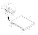
Translated fromKorean도 1은 디스플레이본체가 0도인 상태를 나타낸 휴대용 컴퓨터의 사시도,1 is a perspective view of a portable computer showing a state where the display main body is 0 degrees;
도 2는 디스플레이본체가 90도인 상태에서 회동지지부의 확대도,2 is an enlarged view of the pivot support in a state where the display main body is 90 degrees;
도 3은 디스플레이본체가 180도인 상태를 나타낸 휴대용 컴퓨터의 사시도,3 is a perspective view of a portable computer showing a state where the display body is 180 degrees;
도 4a 및 도 4b는 회동제한부의 작동도,4a and 4b is an operation of the rotation limiting unit,
도 5는 디스플레이본체가 제2회동축의 제2축선을 중심으로 회동되어 270도인 상태를 나타낸 휴대용 컴퓨터의 사시도,5 is a perspective view of a portable computer showing a state in which a display main body is rotated about a second axis of a second pivotal axis at 270 degrees;
도 6은 디스플레이본체가 360도인 상태를 나타낸 휴대용 컴퓨터의 사시도,6 is a perspective view of a portable computer showing a state where the display body is 360 degrees;
도 7은 화상부가 외부로 노출되도록 디스플레이본체가 컴퓨터본체에 대해 접힌 컴퓨터와 지지유닛의 분해상태를 나타낸 후방사시도,7 is a rear perspective view showing an exploded state of a computer and a support unit whose display body is folded with respect to the computer body so that the image part is exposed to the outside;
도 8은 도 7의 전방 사시도이다.8 is a front perspective view of FIG. 7.
* 도면의 주요 부분에 대한 부호의 설명* Explanation of symbols for the main parts of the drawings
1 : 휴대용 컴퓨터2 : 컴퓨터본체1: portable computer 2: computer body
3 : 키보드수용부4 : 키보드유닛3: Keyboard housing 4: Keyboard unit
5 : 디스플레이본체6 : 화상부5: display body 6: image unit
7 : 케이싱8 : 힌지브래킷7: casing 8: hinge bracket
10 : 제1회동지지부11 : 제1회동축10: first pivot support 11: first pivot
12 : 축브래킷13 : 제1축선12: shaft bracket 13: first axis
21 : 제2회동축22 : 축수용부21: 2nd rotation shaft 22: Shaft receiving portion
23 : 제2축선31 : 록킹돌기23: 2nd axis 31: Locking protrusion
32 : 록킹물림부33 : 록킹조작부32: locking locking unit 33: locking operation unit
40 : 지지유닛41 : 베이스부40: support unit 41: base portion
42 : 스탠드부43 : 지지브래킷42: stand portion 43: support bracket
51 : 가동후크52 : 후크결합부51: movable hook 52: hook coupling portion
53 : 결합조작부54 : 결합돌기53: coupling operation unit 54: coupling protrusion
55 : 돌기수용부55: projection receiving part
본 발명은, 컴퓨터장치에 관한 것으로서, 보다 상세하게는, 컴퓨터를 본래 용도로 사용할 수도 있고, 화상부가 외부로 노출되도록 접은 후, 지지유닛에 설치하여 사용할 수도 있음에 따라, 컴퓨터의 활용도를 높일 수 있는 컴퓨터장치에 관한 것이다.The present invention relates to a computer device, and more particularly, a computer may be used for its original purpose, or may be installed in a support unit after being folded so that the image part is exposed to the outside, thereby increasing the utilization of the computer. The present invention relates to a computer device.
일반적으로 컴퓨터는 테이블과 같은 설치면 위에 올려 사용할 수 있 데스크탑 컴퓨터와, 장소에 구애받지 않고 이동하면서 자유로이 사용할 수 있는 휴대용 컴퓨터로 구분된다.Generally, a computer is divided into a desktop computer that can be used on an installation surface such as a table and a portable computer that can be used freely while moving anywhere.
휴대용 컴퓨터의 경우, 이동성이 좋고 휴대가 간편하다는 장점은 있으나, 테 이블과 같은 설치면 위에 올려 놓고 테스크탑 컴퓨터처럼 활용될 수 없어, 실질적인 활용도가 떨어진다는 문제점이 있다.In the case of a portable computer, there is an advantage that it is mobile and easy to carry, but it cannot be used as a desktop computer because it is placed on an installation surface such as a table, and thus there is a problem that the practical use is lowered.
휴대용 컴퓨터의 활용도를 높이기 위한 한 예로 미국특허 US 6,556,435에는 스크린이 전방을 향하도록 접힌 모바일 컴퓨팅 디바이스를 장착할 수 있는 도킹스테이션이 개시되어 있다.As an example to increase the utilization of portable computers, US Pat. No. 6,556,435 discloses a docking station that can be equipped with a mobile computing device with the screen folded forward.
여기서, 도킹스테이션은 설치면에 안착되는 지지플레이트와, 스크린이 전방을 향하도록 접힌 모바일 컴퓨팅 디바이스가 설치되는 리시브 트레이와, 지지플레이트와 리시브 트레이를 연결하는 아암과, 아암을 지지플레이트에 대해 힌지결합하는 힌지부를 포함한다.Here, the docking station includes a support plate seated on the installation surface, a receiving tray on which the mobile computing device is folded so that the screen faces forward, an arm connecting the support plate and the receiving tray, and hinged to the support plate. It includes a hinge portion.
이에, 스크린이 전방을 향하도록 접힌 모바일 컴퓨팅 디바이스를 리시브 트레이에 안착시킨 후, 리시브 트레이를 지지플레이트에 대해 승강시켜 도킹스테이션에 장착된 모바일 컴퓨팅 디바이스의 응시각도를 조절할 수 있게 된다.Accordingly, the mobile computing device, which is folded with the screen facing forward, may be seated on the receive tray, and then the receiver tray may be lifted with respect to the support plate to adjust the gaze angle of the mobile computing device mounted to the docking station.
그런데, 이와 같이, 도킹스테이션과 모바일 컴퓨팅 디바이스를 결합시킨 형태로는, 본래 휴대용 컴퓨터로 사용하고, 휴대용 컴퓨터를 테스크탑 형태의 컴퓨터로도 활용하고자하는 사용자의 욕구를 충족시키기에 부족하다는 문제점이 있다.However, in the form of combining the docking station and the mobile computing device, there is a problem in that it is insufficient to satisfy a user's desire to use a portable computer as a portable computer and to use the portable computer as a desktop computer.
이에 휴대성, 이동성이 강조된 휴대용 컴퓨터의 본래 목적을 충족하면서도, 이러한 휴대용 컴퓨터를 테이블과 같은 설치면 위에 놓고 데스크탑 형태의 컴퓨터로도 활용할 수 있는 수단이 마련된다면, 활용도를 높일 수 있어 바람직할 것이다.In this regard, while meeting the original purpose of the portable computer emphasizing portability and portability, if the portable computer is provided on a mounting surface such as a table and can be used as a desktop computer, it may be desirable to increase the utilization.
따라서, 본 발명의 목적은, 컴퓨터를 본래 용도로 사용할 수도 있고, 화상부 가 외부로 노출되도록 접은 후, 지지유닛에 설치하여 사용할 수도 있음에 따라, 컴퓨터의 활용도를 높일 수 있는 컴퓨터장치를 제공하는 것이다.Accordingly, an object of the present invention is to provide a computer device that can be used for its original purpose, or can be installed in a support unit after being folded to expose the image portion to the outside, thereby increasing the utilization of the computer. will be.
상기 목적은, 본 발명에 따라, 키보드유닛을 착탈가능하게 수용하는 키보드수용부가 마련된 컴퓨터본체와, 화상이 형성되는 화상부를 가지고 상기 컴퓨터본체에 대해 접힘 가능한 디스플레이본체를 갖는 컴퓨터와; 상기 키보드수용부에 착탈가능하게 결합되어, 상기 화상부가 외부로 노출되도록 상기 디스플레이본체가 상기 컴퓨터본체에 대해 접힌 상기 컴퓨터를 설치면에 대해 지지하는 지지유닛을 포함하는 것을 특징으로 하는 컴퓨터장치에 의해 달성된다.According to the present invention, there is provided a computer having a computer main body provided with a keyboard receiving portion detachably accommodating a keyboard unit, and a display body foldable with respect to the computer main body having an image portion on which an image is formed; And a support unit detachably coupled to the keyboard receptacle, for supporting the computer with respect to an installation surface, the display body being folded about the computer body so that the image portion is exposed to the outside. Is achieved.
그리고, 상기 컴퓨터를 상기 지지유닛에 대해 착탈가능하게 결합시키는 결합수단을 더 포함하며, 상기 결합수단은 상기 지지유닛과 상기 키보드수용부 중 어느 하나에 마련된 걸림부와; 상기 지지유닛과 상기 키보드수용부 중 다른 하나에 마련되어 상기 걸림부와 결합가능한 물림부를 포함할 수 있다.And a coupling means for detachably coupling the computer to the support unit, wherein the coupling means comprises: a locking portion provided at any one of the support unit and the keyboard accommodation portion; It may be provided in the other one of the support unit and the keyboard receiving portion may include a bite coupled to the engaging portion.
여기서, 상기 걸림부와 상기 물림부 중 어느 하나는 결합위치와 결합해제위치 간을 이동가능한 가동후크를 포함하고, 상기 걸림부와 상기 물림부 중 다른 하나는 상기 가동후크와 결합하는 후크결합부를 포함하는 것이 바람직하다.Here, any one of the locking portion and the hook portion includes a movable hook that can move between the engaging position and the release position, the other of the locking portion and the hook portion includes a hook coupling portion for engaging with the movable hook. It is desirable to.
또한, 상기 결합수단은 상기 가동후크와 연결되어 상기 가동후크를 상기 후크수용부에 결합 및 결합해제시키는 결합조작부를 더 포함하는 것이 바람직하다.In addition, the coupling means is preferably connected to the movable hook further comprises a coupling operation unit for engaging and releasing the movable hook to the hook receiving portion.
그리고, 상기 걸림부와 상기 물림부 중 어느 하나는 판면으로부터 돌출된 결합돌기를 더 포함하고, 상기 걸림부와 상기 물림부 중 다른 하나는 판면에 함몰형 성된 돌기수용부를 더 포함하는 것이 바람직하다.In addition, any one of the locking portion and the bite portion may further include a coupling protrusion protruding from the plate surface, and the other of the locking portion and the bite portion may further include a protrusion accommodating portion recessed in the plate surface.
한편, 상기 지지유닛은 상기 설치면에 안착되는 베이스부와; 상기 베이스부에 대해 기립방향으로 마련되어, 상기 컴퓨터와 결합하는 스탠드부를 포함할 수 있다.On the other hand, the support unit and the base portion seated on the installation surface; It may include a stand portion provided in the standing direction relative to the base portion, and coupled to the computer.
그리고, 상기 지지유닛은 상기 스탠드부에 마련되며 상기 걸림부와 상기 물림부 중 어느 하나가 마련된 지지브래킷을 더 포함하는 것이 바람직하다.The support unit may further include a support bracket provided on the stand and provided with any one of the locking portion and the biting portion.
또한, 상기 화상부와 상기 컴퓨터본체의 상부면이 상호 이격 및 접근가능하도록, 제1축선을 중심으로 상기 디스플레이본체를 회동지지하는 제1회동지지부와; 상기 디스플레이본체와 상기 컴퓨터본체의 하부면이 상호 이격 및 접근가능하도록, 상기 제1축선과 이격된 제2축선을 중심으로 상기 디스플레이본체를 회동지지하는 제2회동지지부를 포함하는 것이 바람직하다.In addition, a first rotation support portion for pivotally supporting the display body about a first axis so that the image portion and the upper surface of the computer body are spaced apart and accessible to each other; Preferably, the display main body includes a second pivotal support pivoting the display main body about a second axis spaced apart from the first axis so that the bottom surface of the display main body and the computer main body are spaced apart and accessible.
그리고, 상기 컴퓨터본체와 상기 디스플레이본체를 연결하며, 상기 제2축선을 중심으로 상기 컴퓨터본체에 대해 회동가능한 힌지브래킷을 더 포함할 수 있다.The hinge unit may further include a hinge bracket that connects the computer body and the display body and is rotatable with respect to the computer body about the second axis.
여기서, 상기 제2회동지지부는 상기 힌지브래킷과 상기 컴퓨터본체 중 어느 하나에 마련된 제2회동축과; 상기 힌지브래킷과 상기 컴퓨터본체 중 다른 하나에 마련되어 상기 제2회동축을 회동가능하게 수용하는 제2축수용부를 포함하는 것이 바람직하다.Here, the second rotation support portion and the second rotation shaft provided in any one of the hinge bracket and the computer body; It is preferable to include a second shaft accommodating portion provided on the other of the hinge bracket and the computer main body to accommodate the second rotation shaft rotatably.
또한, 상기 제2축선을 중심으로 상기 디스플레이본체가 회동되는 것을 저지 및 허용하는 회동제한부를 더 포함하며, 상기 회동제한부는 상기 힌지브래킷과 상기 컴퓨터본체 중 어느 하나에 마련된 록킹돌기와; 상기 힌지브래킷과 상기 컴퓨터 본체 중 다른 하나에 마련되어 상기 록킹돌기와 물림가능한 록킹물림부를 포함할 수 있다.The apparatus may further include a rotation limiter configured to prevent and allow the display body to be rotated about the second axis, wherein the rotation limiter includes a locking protrusion provided at any one of the hinge bracket and the computer body; The hinge bracket may be provided on the other one of the computer main body and may include the locking protrusion and the locking engagement portion.
여기서, 상기 회동제한부는 상기 록킹돌기에 연결되어 상기 록킹돌기를 상기 록킹물림부에 물림 및 물림해제시키는 록킹조작부를 더 포함할 수 있다.Here, the rotation limiting unit may further include a locking operation unit connected to the locking protrusion to bite and release the locking protrusion into the locking bite.
한편, 상기 제1회동지지부는 상기 디스플레이본체와 상기 힌지브래킷을 연결하는 제1회동축과; 상기 힌지브래킷에 마련되어 상기 제1회동축을 회동가능하게 수용하는 축브래킷을 포함하는 것이 바람직하다.On the other hand, the first pivot support portion and the first pivot for connecting the display body and the hinge bracket; It is preferable to include a shaft bracket provided on the hinge bracket for rotatably receiving the first rotating shaft.
이하 첨부도면을 참조하여 본 발명에 대해 상세히 설명한다.Hereinafter, the present invention will be described in detail with reference to the accompanying drawings.
본 발명에 따른 컴퓨터장치는 도 1의 휴대용 컴퓨터(1)를 포함하며, 도 1에 도시된 바와 같이, 휴대용 컴퓨터(1)는 컴퓨터본체(2)와, 컴퓨터본체(2)로부터 화상신호를 화면으로 표시하는 화상부(6)를 갖는 디스플레이본체(5)를 포함한다. 여기서 디스플레이본체(5)는 컴퓨터본체(2)에 대해 제1 및 제2축선(13,23)을 중심으로 회동가능하게 마련되어 있다.The computer device according to the present invention includes the
도 1에 도시된 휴대용 컴퓨터(1)의 후방 측에는 제2축선(23)을 중심으로 컴퓨터본체(2)에 대해 회동가능한 힌지브래킷(8)이 마련되어 있고, 제2축선(23)을 중심으로 한 힌지브래킷(8)의 회동 및 회동저지를 조작할 수 있는 록킹조작부(33)가 마련되어 있다.On the rear side of the
컴퓨터본체(2)의 내부에는 메인보드, CPU, RAM 등을 포함한 다수의 하드웨어가 수용되어 있으며, 상측에는 키보드유닛(4)을 포함한 입력장치가 마련되어 있다. 여기서, 키보드유닛(4)은 컴퓨터본체(2)의 상부에 함몰 형성된 키보드수용부(3)에 착탈가능하게 수용되어 있다.Inside the
디스플레이본체(5)는 화상을 형성하는 화상부(6)와, 화상부(6)를 지지하는 케이싱(7)을 포함하며,도 1의 디스플레이본체(5)는 컴퓨터본체(2)에 대해 0도를 이루며, 화상부(6)가 외부로 노출되지 않도록 컴퓨터본체(2)에 대해 접힌 상태이다.The display
디스플레이본체(5)는 도 2의 회동지지부(10,21,22)에 의해 컴퓨터본체(2)에 대해 회동가능하게 지지된다. 회동지지부(10,21,22)는 도 2에 도시된 바와 같이, 화상부(6)와 컴퓨터본체(2)의 상부면이 상호 이격 및 접근가능하도록, 제1축선(13)을 중심으로 디스플레이본체(5)를 회동지지하는 제1회동지지부(10)와, 디스플레이본체(5)와 컴퓨터본체(2)의 하부면이 상호 이격 및 접근가능하도록, 제1축선(13)과 이격된 제2축선(23)을 중심으로 디스플레이본체(5)를 회동지지하는 제2회동지지부(21,22)를 포함한다.The display
제1회동지지부(10)는 컴퓨터본체(2)에 대해 0도에서 180도까지 디스플레이본체(5)의 회동을 지지한다. 그리고, 제1회동지지부(10)는 디스플레이본체(5)와 힌지브래킷(8)을 연결하며 제1축선(13)을 형성하는 제1회동축(11)과, 힌지브래킷(8)에 마련되어 제1회동축(11)을 회동가능하게 수용하는 축브래킷(12)을 포함한다. 이에 디스플레이본체(5)는 제1회동축(11)의 제1축선(13)을 중심으로 0도에서 180도 간을 회동할 수 있게 된다. 여기서, 180도는 도 3에 도시된 바와 같이, 디스플레이본체(5)가 컴퓨터본체(2)와 거의 나란하게 배치되도록 펼쳐진 상태이다.The
제2회동지지부(21,22)는 컴퓨터본체(2)에 대해 180도에서 360도까지 디스플 레이본체(5)의 회동을 지지한다. 그리고, 회동지지부(21,22)는 힌지브래킷(8)의 단부영역에 마련되어 제1축선(13)과 이격된 제2축선(23)을 형성하는 제2회동축(21)과, 컴퓨터본체(2)에 마련되어 제2회동축(21)을 회동가능하게 수용하는 제2축수용부(22)를 포함한다. 이에 디스플레이본체(5)는 제2회동축(21)의 제2축선(23)을 중심으로 180도에서 360도 간을 회동할 수 있게 된다.The second
한편, 제2축선(23)을 중심으로 한 디스플레이본체(5)의 회동은 도 4a 및 도 4b에 도시된 회동제한부에 의해 저지 및 허용된다.On the other hand, the rotation of the display
회동제어부(31,32,33)는 컴퓨터본체(2)에 대해 이동가능하게 마련된 록킹돌기(31)와, 힌지브래킷(8)에 마련되어 록킹돌기(31)와 물림가능한 록킹물림부(32)와, 록킹돌기(31)에 연결되어 록킹돌기(31)를 록킹물림부(32)에 물림 및 물림해제시키는 록킹조작부(33)를 포함한다.The
여기서, 록킹돌기(31)과 록킹물림부(32)의 물림이 해제되면, 디스플레이본체(5)는 도 5에 도시된 바와 같이 제2축선(23)을 중심으로 회동되어, 도 6에 도시된 바와 같이 360도까지 회전될 수 있게 된다. 360도는 도 6에 도시된 바와 같이, 화상부(6)가 외부로 노출되도록 디스플레이본체(5)가 컴퓨터본체(2)에 대해 접힌 상태이다. 즉, 360도에서는 디스플레이본체(5)가 컴퓨터본체(2)의 바닥면에 접촉된다.Here, when the locking
한편, 본 발명에 따른 컴퓨터장치는 도 6에 도시된 바와 같이, 디스플레이본체(5)가 컴퓨터본체(2)의 바닥면에 밀착되도록 접히고, 키보드수용부(3)로부터 키보드유닛(4)이 분리된 상태의 휴대용 컴퓨터(1)를, 설치면에 대해 지지하는 도 7 및 도 8의 지지유닛(40)을 더 포함한다.On the other hand, the computer device according to the present invention, as shown in Figure 6, the display
즉, 키보드수용부(3)로부터 키보드유닛(4)이 분리된 휴대용 컴퓨터(1)를 도 7 및 도 8에 도시된 결합수단(51,52,53,54,55)을 이용하여 지지유닛(40)에 결합시킨다.That is, the
도 7 및 도 8에 도시된 바와 같이, 지지유닛(40)은 테이블과 같은 수평면에 안착되는 베이스부(41)와, 베이스부(41)에 대해 기립방향으로 마련된 스탠드부(42)와, 휴대용 컴퓨터(1)를 스탠드부(42)에 대해 지지하는 지지브래킷(43)을 포함한다. 여기서, 지지유닛(40)은 도면에 도시된 이외에도 다양한 형태로 마련될 수 있다. 또한, 지지유닛(40)에서 휴대용 컴퓨터(1)가 승강, 틸팅, 스위블, 회동가능하도록 지지유닛(40)이 마련된다면 지지유닛(40)에 장착된 휴대용 컴퓨터(1)의 응시각도가 다양하게 제공될 수 있어 더욱 바람직하다.As shown in FIGS. 7 and 8, the
결합수단(51,52,53,54,55)은 컴퓨터본체(2)의 상부면에 형성된 키보드수용부(3)에 마련된 가동후크(51)와, 지지브래킷(43)에 마련되어 가동후크(51)와 물림가능한 후크결합부(52)와, 키보드수용부(3)에 마련된 돌기수용부(55)와, 지지브래킷(43)에 마련되어 돌기수용부(55)에 삽입되는 결합돌기(54)를 포함한다. 그리고, 결합수단(51,52,53,54,55)은 가동후크(51)와 연결되어 가동후크(51)를 후크수용부에 결합 및 결합해제시키는 결합조작부(53)를 더 포함한다.Coupling means (51, 52, 53, 54, 55) is provided on the
이러한 구성을 갖는 컴퓨터장치에 있어서, 이하에서는 휴대용 컴퓨터(1)를 지지유닛(40)에 설치하지 않고 사용하는 방법과 휴대용 컴퓨터(1)를 지지유닛(40)에 장착시켜 사용하는 방법으로 나누어서 설명하기로 하다.In the computer device having such a configuration, hereinafter, the
우선 도 1에 도시된 바와 같이, 디스플레이본체(5)가 컴퓨터본체(2)에 대해 0도인 상태를 기준으로 하여, 디스플레이본체(5)를 제1축선(13)을 중심으로 회동시켜 디스플레이본체(5)가 도 2에 도시된 바와 같이, 컴퓨터본체(2)에 대해 거의 90도를 이루도록 배치시킨다. 이러한 상태에서 사용자는 휴대용 컴퓨터(1)를 테이블과 같은 설치면 위에 직접 안착시킨 상태에서 사용할 수 있게 된다.First, as shown in FIG. 1, on the basis of a state where the display
또한, 휴대용 컴퓨터(1)를 테이블과 같은 설치면 위에 안착되는 지지유닛(40)에 결합시켜 사용할 수도 있다.In addition, the
도 2에 도시된 바와 같이, 디스플레이본체(5)가 컴퓨터본체(2)에 대해 거의 90도인 상태를 기준으로 하여, 디스플레이본체(5)를 제1축선(13)을 중심으로 회동시켜, 디스플레이본체(5)가 도 3에 도시된 바와 같이, 컴퓨터본체(2)에 대해 180도를 이루도록 배치시킨다. 이때, 도 4a에 도시된 바와 같이, 컴퓨터본체(2)의 록킹돌기(31)가 힌지브래킷(8)의 록킹물림부(32)에 걸려 있는 상태이다. 이 상태에서 디스플레이본체(5)는 제2회동축(21)의 제2축선(23)을 중심으로 180도에서 360도 까지 회동될 수 없다.As shown in FIG. 2, the display
이에 록킹조작부(33)를 도 4a의 A방향으로 밀게 되면, 도 4b에 도시된 바와 같이, 록킹돌기(31)와 록킹물림부(32)의 걸림이 해제됨에 따라, 디스플레이본체(5)가 제2회동축(21)의 제2축선(23)을 중심으로 도 4b의 180도에서 도 5의 270도를 거쳐 도 6의 360도 까지 회동가능한 상태가 된다.When the locking
따라서, 디스플레이본체(5)를 제2회동축(21)의 제2축선(23)을 중심으로 회동시켜 최종적으로 도 6에 도시된 바와 같이 디스플레이본체(5)를 컴퓨터본체(2)의 바닥면에 밀착시킨다. 도 6에 도시된 바와 같이, 디스플레이본체(5)가 360도로 회동된 상태에서는, 디스플레이본체(5)의 후방면과 컴퓨터본체(2)의 바닥면이 상호 마주보도록 디스플레이본체(5)가 컴퓨터본체(2)에 대해 접히게 된다.Accordingly, the display
다음으로 컴퓨터본체(2)의 키보드수용부(3)로부터 키보드유닛(4)을 분리하면, 키보드수용부(3)를 통해서, 가동후크(51) 및 돌기수용부(55)가 외부로 노출된다.Next, when the
이러한 상태에서 도 7 및 도 8에 도시된 바와 같이, 컴퓨터본체(2)의 돌기수용부(55)에 지지브래킷(43)의 결합돌기(54)를 삽입하고, 컴퓨터본체(2)의 가동후크(51)와 지지브래킷(43)의 후크결합부(52)가 맞물리도록 결합시킨다. 이에 화상부(6)가 전방을 향하도록 디스플레이본체(5)가 컴퓨터본체(2)에 대해 접힌 휴대용 컴퓨터(1)를 지지유닛(40)에 장착하는 작업이 완료된다. 이와 같이, 사용자는 휴대용 컴퓨터(1)를 지지유닛(40)에 장착하여, 테이블과 같은 설치면에 위에 놓고 사용할 수 있게 된다.7 and 8, the
한편, 휴대용 컴퓨터(1)를 지지유닛(40)으로부터 분리하여 사용하고자 할 때는, 결합조작부(53)를 가압하여, 컴퓨터본체(2)의 가동후크(51)와 지지브래킷(43)의 후크결합부(52)의 물림을 해제시킴으로써, 간편하게 지지유닛(40)으로부터 휴대용 컴퓨터(1)를 분리시킬 수 있다.On the other hand, when the
이와 같이, 본 발명에 따른 컴퓨터장치에 있어서, 휴대용 컴퓨터(1)를 본래 용도 대로 사용할 수도 있고, 화상부(6)가 외부로 노출되도록 접어서 지지유닛(40)에 장착한 후 테이블과 같은 설치면에 놓고 테스크탑 형태의 컴퓨터로도 사용할 수 있음에 따라, 휴대용 컴퓨터(1)의 활용도를 높일 수 있게 된다.As described above, in the computer device according to the present invention, the
또한, 지지유닛(40)에 결합된 휴대용 컴퓨터(1)를 결합조작부(53)를 이용하여 간편하게 지지유닛(40)으로부터 분리시킬 수 있게 된다.In addition, the
이상 설명한 바와 같이, 본 발명에 따르면, 컴퓨터를 본래 용도로 사용할 수도 있고, 화상부가 외부로 노출되도록 접은 후, 지지유닛에 설치하여 사용할 수도 있음에 따라, 컴퓨터의 활용도를 높일 수 있게 된다.As described above, according to the present invention, the computer may be used for its original purpose, or the image part may be folded and exposed to the outside, and then installed in a support unit, thereby increasing the utilization of the computer.
Claims (13)
Translated fromKoreanPriority Applications (2)
| Application Number | Priority Date | Filing Date | Title |
|---|---|---|---|
| KR1020040105523AKR100654797B1 (en) | 2004-12-14 | 2004-12-14 | Computer devices |
| US11/274,186US7336480B2 (en) | 2004-12-14 | 2005-11-16 | Computer system |
Applications Claiming Priority (1)
| Application Number | Priority Date | Filing Date | Title |
|---|---|---|---|
| KR1020040105523AKR100654797B1 (en) | 2004-12-14 | 2004-12-14 | Computer devices |
Publications (2)
| Publication Number | Publication Date |
|---|---|
| KR20060067159A KR20060067159A (en) | 2006-06-19 |
| KR100654797B1true KR100654797B1 (en) | 2006-12-08 |
Family
ID=36583544
Family Applications (1)
| Application Number | Title | Priority Date | Filing Date |
|---|---|---|---|
| KR1020040105523AExpired - Fee RelatedKR100654797B1 (en) | 2004-12-14 | 2004-12-14 | Computer devices |
Country Status (2)
| Country | Link |
|---|---|
| US (1) | US7336480B2 (en) |
| KR (1) | KR100654797B1 (en) |
Families Citing this family (12)
| Publication number | Priority date | Publication date | Assignee | Title |
|---|---|---|---|---|
| CN2842521Y (en)* | 2005-08-12 | 2006-11-29 | 鸿富锦精密工业(深圳)有限公司 | Notebook computer with detachable display module group |
| JP4405532B2 (en)* | 2007-07-04 | 2010-01-27 | シャープ株式会社 | Foldable mobile phone |
| WO2009146042A2 (en)* | 2008-03-31 | 2009-12-03 | Terra Soft Solutions Of Colorado, Inc. | Tablet computer |
| CN101650598A (en)* | 2008-08-11 | 2010-02-17 | 鸿富锦精密工业(深圳)有限公司 | Keyboard |
| CN102334081B (en)* | 2009-02-28 | 2014-01-15 | 惠普开发有限公司 | Latch system and method of operating the latch system |
| CN102076200B (en)* | 2009-11-24 | 2014-11-05 | 鸿富锦精密工业(深圳)有限公司 | Electronic equipment |
| US8749963B2 (en)* | 2010-03-15 | 2014-06-10 | Over The Sun, Llc | Housing for slate tablet computer |
| TWI422751B (en)* | 2011-08-11 | 2014-01-11 | Wistron Corp | Magnetic switch device and electronic device having the same |
| US20130088825A1 (en)* | 2011-10-11 | 2013-04-11 | Lenovo (Singapore) Pte. Ltd. | Notebook pc having three layers |
| JP6124213B2 (en)* | 2012-09-04 | 2017-05-10 | パナソニックIpマネジメント株式会社 | Electronics |
| TWI502322B (en)* | 2013-05-23 | 2015-10-01 | Wistron Corp | Portable electronic device |
| US10976782B2 (en)* | 2018-12-21 | 2021-04-13 | Intel Corporation | Offset hinge assembly for mobile compute devices |
Citations (5)
| Publication number | Priority date | Publication date | Assignee | Title |
|---|---|---|---|---|
| JPH10228333A (en)* | 1997-02-13 | 1998-08-25 | Bunji Koshiishi | Notebook type personal computer with two hinges |
| KR19990007710U (en)* | 1997-07-31 | 1999-02-25 | 윤종용 | Video display device |
| JP2001117673A (en) | 1999-10-20 | 2001-04-27 | Arima Computer Corp | Portable computer having lcd rotatable at 360 degrees |
| JP2003058276A (en)* | 2001-08-09 | 2003-02-28 | Sharp Corp | Portable information processing device |
| JP2004240495A (en) | 2003-02-03 | 2004-08-26 | Sharp Corp | Information processing equipment |
Family Cites Families (13)
| Publication number | Priority date | Publication date | Assignee | Title |
|---|---|---|---|---|
| KR0175730B1 (en) | 1996-09-06 | 1999-04-15 | 김정국 | Double acting cylinder |
| US6556435B1 (en) | 1997-10-31 | 2003-04-29 | Hewlett-Packard Company | Adjustable height docking station and computing device for use therewith |
| US6266241B1 (en) | 1999-09-29 | 2001-07-24 | Hewlett-Packard Company | Notebook computer with ergonomic stand |
| US6788527B2 (en)* | 2002-05-31 | 2004-09-07 | Hewlett-Packard Development Company, L.P. | Tablet computer keyboard and system and method incorporating same |
| US7126588B2 (en)* | 2002-06-27 | 2006-10-24 | Intel Corporation | Multiple mode display apparatus |
| US7109893B2 (en)* | 2002-07-18 | 2006-09-19 | Mitac Technology Corp. | Notebook computer with a detachable keyboard |
| US6751089B2 (en)* | 2002-09-20 | 2004-06-15 | Taiwan Trigem Information Co., Ltd. | Keyboard securing device of notebook computer |
| JP2004178540A (en)* | 2002-11-27 | 2004-06-24 | Shinsuke Hamaji | Notebook type information terminal |
| US6903927B2 (en)* | 2002-12-17 | 2005-06-07 | Nokia Corporation | Convertible mobile computing device |
| TWI241513B (en)* | 2003-03-26 | 2005-10-11 | Benq Corp | Detachable keyboard structure |
| US6975507B2 (en)* | 2003-06-23 | 2005-12-13 | Inventec Corporation | Structure of notebook computer |
| TWM249084U (en)* | 2003-12-31 | 2004-11-01 | Tatung Co | Support structure for portable computer |
| US20050206615A1 (en)* | 2004-03-22 | 2005-09-22 | Mitsuyoshi Tanimoto | Display support mechanism for an electronic apparatus |
- 2004
- 2004-12-14KRKR1020040105523Apatent/KR100654797B1/ennot_activeExpired - Fee Related
- 2005
- 2005-11-16USUS11/274,186patent/US7336480B2/ennot_activeExpired - Fee Related
Patent Citations (5)
| Publication number | Priority date | Publication date | Assignee | Title |
|---|---|---|---|---|
| JPH10228333A (en)* | 1997-02-13 | 1998-08-25 | Bunji Koshiishi | Notebook type personal computer with two hinges |
| KR19990007710U (en)* | 1997-07-31 | 1999-02-25 | 윤종용 | Video display device |
| JP2001117673A (en) | 1999-10-20 | 2001-04-27 | Arima Computer Corp | Portable computer having lcd rotatable at 360 degrees |
| JP2003058276A (en)* | 2001-08-09 | 2003-02-28 | Sharp Corp | Portable information processing device |
| JP2004240495A (en) | 2003-02-03 | 2004-08-26 | Sharp Corp | Information processing equipment |
Also Published As
| Publication number | Publication date |
|---|---|
| US7336480B2 (en) | 2008-02-26 |
| KR20060067159A (en) | 2006-06-19 |
| US20060126281A1 (en) | 2006-06-15 |
Similar Documents
| Publication | Publication Date | Title |
|---|---|---|
| US6583985B2 (en) | Elevationally adjustable portable computer docking station | |
| JP3665164B2 (en) | Equipment for supporting portable computers | |
| KR100654797B1 (en) | Computer devices | |
| US7492579B2 (en) | Computer with adjustable display | |
| US7129931B2 (en) | Multipurpose computer display system | |
| US5822185A (en) | Ergonomic docking station for a portable computer | |
| US9125289B2 (en) | Asymmetric computer tablet frame docking system | |
| US7277275B2 (en) | Portable computer having adjustable display | |
| US7298610B2 (en) | Supporting apparatus for portable computer | |
| EP1093605A1 (en) | Desktop portable computer vertical dock system | |
| CN209325304U (en) | Supporting component and electronic device using same | |
| US9348376B2 (en) | Tablet information handling system display stand with flexible power connection | |
| US20120224323A1 (en) | Tablet pc supplementary device | |
| TW200901111A (en) | Adjustable display | |
| US10890944B1 (en) | Tablet support stand | |
| US20050270731A1 (en) | Computer docking system | |
| US8526178B2 (en) | All-in-one computing device with an adjustable screen height | |
| CN103425196B (en) | electronic device | |
| JP6507207B2 (en) | Accessory equipment and electronic equipment | |
| JP2003058276A (en) | Portable information processing device | |
| KR101314228B1 (en) | docking station for portable computer | |
| JP2002116844A (en) | Note-sized personal computer stand and base body therefor | |
| JP2001273050A (en) | Function expansion connector stand for pen input computer | |
| JPH0555214U (en) | Notebook personal computer | |
| KR20050103086A (en) | A port replicator |
Legal Events
| Date | Code | Title | Description |
|---|---|---|---|
| A201 | Request for examination | ||
| PA0109 | Patent application | St.27 status event code:A-0-1-A10-A12-nap-PA0109 | |
| PA0201 | Request for examination | St.27 status event code:A-1-2-D10-D11-exm-PA0201 | |
| PN2301 | Change of applicant | St.27 status event code:A-3-3-R10-R13-asn-PN2301 St.27 status event code:A-3-3-R10-R11-asn-PN2301 | |
| PN2301 | Change of applicant | St.27 status event code:A-3-3-R10-R13-asn-PN2301 St.27 status event code:A-3-3-R10-R11-asn-PN2301 | |
| D13-X000 | Search requested | St.27 status event code:A-1-2-D10-D13-srh-X000 | |
| D14-X000 | Search report completed | St.27 status event code:A-1-2-D10-D14-srh-X000 | |
| E902 | Notification of reason for refusal | ||
| PE0902 | Notice of grounds for rejection | St.27 status event code:A-1-2-D10-D21-exm-PE0902 | |
| PG1501 | Laying open of application | St.27 status event code:A-1-1-Q10-Q12-nap-PG1501 | |
| E701 | Decision to grant or registration of patent right | ||
| PE0701 | Decision of registration | St.27 status event code:A-1-2-D10-D22-exm-PE0701 | |
| GRNT | Written decision to grant | ||
| PR0701 | Registration of establishment | St.27 status event code:A-2-4-F10-F11-exm-PR0701 | |
| PR1002 | Payment of registration fee | St.27 status event code:A-2-2-U10-U11-oth-PR1002 Fee payment year number:1 | |
| PG1601 | Publication of registration | St.27 status event code:A-4-4-Q10-Q13-nap-PG1601 | |
| PR1001 | Payment of annual fee | St.27 status event code:A-4-4-U10-U11-oth-PR1001 Fee payment year number:4 | |
| PR1001 | Payment of annual fee | St.27 status event code:A-4-4-U10-U11-oth-PR1001 Fee payment year number:5 | |
| PR1001 | Payment of annual fee | St.27 status event code:A-4-4-U10-U11-oth-PR1001 Fee payment year number:6 | |
| R18-X000 | Changes to party contact information recorded | St.27 status event code:A-5-5-R10-R18-oth-X000 | |
| FPAY | Annual fee payment | Payment date:20121030 Year of fee payment:7 | |
| PR1001 | Payment of annual fee | St.27 status event code:A-4-4-U10-U11-oth-PR1001 Fee payment year number:7 | |
| FPAY | Annual fee payment | Payment date:20131030 Year of fee payment:8 | |
| PR1001 | Payment of annual fee | St.27 status event code:A-4-4-U10-U11-oth-PR1001 Fee payment year number:8 | |
| FPAY | Annual fee payment | Payment date:20141030 Year of fee payment:9 | |
| PR1001 | Payment of annual fee | St.27 status event code:A-4-4-U10-U11-oth-PR1001 Fee payment year number:9 | |
| FPAY | Annual fee payment | Payment date:20151029 Year of fee payment:10 | |
| PR1001 | Payment of annual fee | St.27 status event code:A-4-4-U10-U11-oth-PR1001 Fee payment year number:10 | |
| LAPS | Lapse due to unpaid annual fee | ||
| PC1903 | Unpaid annual fee | St.27 status event code:A-4-4-U10-U13-oth-PC1903 Not in force date:20161201 Payment event data comment text:Termination Category : DEFAULT_OF_REGISTRATION_FEE | |
| PC1903 | Unpaid annual fee | St.27 status event code:N-4-6-H10-H13-oth-PC1903 Ip right cessation event data comment text:Termination Category : DEFAULT_OF_REGISTRATION_FEE Not in force date:20161201 |