KR100654103B1 - Dye-Sensitized Solar Cell Module Using Carbon Nanotube Electrode - Google Patents
Dye-Sensitized Solar Cell Module Using Carbon Nanotube ElectrodeDownload PDFInfo
- Publication number
- KR100654103B1 KR100654103B1KR1020050115361AKR20050115361AKR100654103B1KR 100654103 B1KR100654103 B1KR 100654103B1KR 1020050115361 AKR1020050115361 AKR 1020050115361AKR 20050115361 AKR20050115361 AKR 20050115361AKR 100654103 B1KR100654103 B1KR 100654103B1
- Authority
- KR
- South Korea
- Prior art keywords
- electrode
- carbon nanotube
- dye
- solar cell
- sensitized solar
- Prior art date
- Legal status (The legal status is an assumption and is not a legal conclusion. Google has not performed a legal analysis and makes no representation as to the accuracy of the status listed.)
- Active
Links
Images


Classifications
- H—ELECTRICITY
- H01—ELECTRIC ELEMENTS
- H01G—CAPACITORS; CAPACITORS, RECTIFIERS, DETECTORS, SWITCHING DEVICES, LIGHT-SENSITIVE OR TEMPERATURE-SENSITIVE DEVICES OF THE ELECTROLYTIC TYPE
- H01G9/00—Electrolytic capacitors, rectifiers, detectors, switching devices, light-sensitive or temperature-sensitive devices; Processes of their manufacture
- H01G9/20—Light-sensitive devices
- H01G9/2022—Light-sensitive devices characterized by he counter electrode
- H—ELECTRICITY
- H01—ELECTRIC ELEMENTS
- H01M—PROCESSES OR MEANS, e.g. BATTERIES, FOR THE DIRECT CONVERSION OF CHEMICAL ENERGY INTO ELECTRICAL ENERGY
- H01M4/00—Electrodes
- H01M4/02—Electrodes composed of, or comprising, active material
- H01M4/36—Selection of substances as active materials, active masses, active liquids
- H01M4/58—Selection of substances as active materials, active masses, active liquids of inorganic compounds other than oxides or hydroxides, e.g. sulfides, selenides, tellurides, halogenides or LiCoFy; of polyanionic structures, e.g. phosphates, silicates or borates
- H01M4/583—Carbonaceous material, e.g. graphite-intercalation compounds or CFx
- H—ELECTRICITY
- H10—SEMICONDUCTOR DEVICES; ELECTRIC SOLID-STATE DEVICES NOT OTHERWISE PROVIDED FOR
- H10F—INORGANIC SEMICONDUCTOR DEVICES SENSITIVE TO INFRARED RADIATION, LIGHT, ELECTROMAGNETIC RADIATION OF SHORTER WAVELENGTH OR CORPUSCULAR RADIATION
- H10F77/00—Constructional details of devices covered by this subclass
- H10F77/20—Electrodes
- H10F77/206—Electrodes for devices having potential barriers
- H10F77/211—Electrodes for devices having potential barriers for photovoltaic cells
- H—ELECTRICITY
- H10—SEMICONDUCTOR DEVICES; ELECTRIC SOLID-STATE DEVICES NOT OTHERWISE PROVIDED FOR
- H10K—ORGANIC ELECTRIC SOLID-STATE DEVICES
- H10K85/00—Organic materials used in the body or electrodes of devices covered by this subclass
- H10K85/20—Carbon compounds, e.g. carbon nanotubes or fullerenes
- H10K85/221—Carbon nanotubes
- Y—GENERAL TAGGING OF NEW TECHNOLOGICAL DEVELOPMENTS; GENERAL TAGGING OF CROSS-SECTIONAL TECHNOLOGIES SPANNING OVER SEVERAL SECTIONS OF THE IPC; TECHNICAL SUBJECTS COVERED BY FORMER USPC CROSS-REFERENCE ART COLLECTIONS [XRACs] AND DIGESTS
- Y02—TECHNOLOGIES OR APPLICATIONS FOR MITIGATION OR ADAPTATION AGAINST CLIMATE CHANGE
- Y02E—REDUCTION OF GREENHOUSE GAS [GHG] EMISSIONS, RELATED TO ENERGY GENERATION, TRANSMISSION OR DISTRIBUTION
- Y02E10/00—Energy generation through renewable energy sources
- Y02E10/50—Photovoltaic [PV] energy
- Y02E10/542—Dye sensitized solar cells
- Y—GENERAL TAGGING OF NEW TECHNOLOGICAL DEVELOPMENTS; GENERAL TAGGING OF CROSS-SECTIONAL TECHNOLOGIES SPANNING OVER SEVERAL SECTIONS OF THE IPC; TECHNICAL SUBJECTS COVERED BY FORMER USPC CROSS-REFERENCE ART COLLECTIONS [XRACs] AND DIGESTS
- Y02—TECHNOLOGIES OR APPLICATIONS FOR MITIGATION OR ADAPTATION AGAINST CLIMATE CHANGE
- Y02E—REDUCTION OF GREENHOUSE GAS [GHG] EMISSIONS, RELATED TO ENERGY GENERATION, TRANSMISSION OR DISTRIBUTION
- Y02E10/00—Energy generation through renewable energy sources
- Y02E10/50—Photovoltaic [PV] energy
- Y02E10/549—Organic PV cells
- Y—GENERAL TAGGING OF NEW TECHNOLOGICAL DEVELOPMENTS; GENERAL TAGGING OF CROSS-SECTIONAL TECHNOLOGIES SPANNING OVER SEVERAL SECTIONS OF THE IPC; TECHNICAL SUBJECTS COVERED BY FORMER USPC CROSS-REFERENCE ART COLLECTIONS [XRACs] AND DIGESTS
- Y02—TECHNOLOGIES OR APPLICATIONS FOR MITIGATION OR ADAPTATION AGAINST CLIMATE CHANGE
- Y02E—REDUCTION OF GREENHOUSE GAS [GHG] EMISSIONS, RELATED TO ENERGY GENERATION, TRANSMISSION OR DISTRIBUTION
- Y02E60/00—Enabling technologies; Technologies with a potential or indirect contribution to GHG emissions mitigation
- Y02E60/10—Energy storage using batteries
Landscapes
- Engineering & Computer Science (AREA)
- Chemical & Material Sciences (AREA)
- Power Engineering (AREA)
- Materials Engineering (AREA)
- Nanotechnology (AREA)
- Microelectronics & Electronic Packaging (AREA)
- Inorganic Chemistry (AREA)
- Chemical Kinetics & Catalysis (AREA)
- Electrochemistry (AREA)
- General Chemical & Material Sciences (AREA)
- Hybrid Cells (AREA)
- Photovoltaic Devices (AREA)
Abstract
Translated fromKoreanDescription
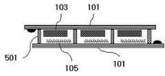
Translated fromKorean도 1은 본 발명에 따른 탄소나노튜브를 이용한 염료감응형 태양전지 모듈에 채용되는 단위 염료감응형 태양전지의 구조를 개략적으로 보여주는 도면.1 is a view schematically showing the structure of a unit dye-sensitized solar cell employed in a dye-sensitized solar cell module using carbon nanotubes according to the present invention.
도 2는 도 1의 염료감응형 태양전지에서 탄소나노튜브막에 사용된 여러 종류의 탄소나노튜브의 전자현미경 사진.Figure 2 is an electron micrograph of the various types of carbon nanotubes used in the carbon nanotube film in the dye-sensitized solar cell of Figure 1;
도 3은 본 발명에 채용되는 금속계 탄소나노튜브의 전자현미경 사진.3 is an electron micrograph of metal-based carbon nanotubes employed in the present invention.
도 4는 본 발명에 채용되는 2개 이상의 단위 염료감응형 태양전지를 연결하여 구성된 태양전지 모듈에서 연결전극의 일 예를 보여주는 기판 패턴의 도면.4 is a diagram of a substrate pattern showing an example of a connection electrode in a solar cell module configured by connecting two or more unit dye-sensitized solar cells employed in the present invention.
도 5는 본 발명에 채용되는 2개 이상의 단위 염료감응형 태양전지를 연결하여 구성된 태양전지 모듈에서 단위 태양전지 사이의 단락을 방지하기 위한 탄소나노튜브 절연막을 보여주는 모식도.5 is a schematic diagram showing a carbon nanotube insulating film for preventing a short circuit between unit solar cells in a solar cell module configured by connecting two or more unit dye-sensitized solar cells employed in the present invention.
도 6은 본 발명에 채용되는 다중벽 탄소나노튜브와 CMC 결합제를 사용하여 제조한 탄소나노튜브 전극막의 전자현미경 사진.6 is an electron micrograph of a carbon nanotube electrode membrane prepared using a multi-walled carbon nanotube and a CMC binder employed in the present invention.
도 7은 본 발명에 채용되는 탄소나노튜브 전극막을 전기전도성이 없는 유리기판 위에 투명에서 불투명까지의 투과도를 보여주도록 제조된 시편의 사진.Figure 7 is a photograph of a specimen prepared to show the transparent to opaque carbon nanotube electrode film employed in the present invention on a glass substrate without electrical conductivity.
도 8은 본 발명에 채용되는 탄소나노튜브 페이스트를 볼밀을 사용하여 제조 하는 모습과 혼합에 사용된 원형과 실린더형의 볼을 보여주는 도면.8 is a view showing a round and cylindrical balls used for mixing and mixing the carbon nanotube paste employed in the present invention using a ball mill.
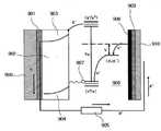
도 9는 탄소나노튜브를 지닌 염료감응형 태양전지 소자의 작동 원리를 도식적으로 보여주는 도면.9 is a schematic view showing the operating principle of the dye-sensitized solar cell device with carbon nanotubes.
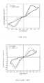
도 10은 종래의 백금전극과 탄소나노튜브 전극에 대한 전해질의 산화환원 반응의 CV(cyclic voltametry) 측정 결과를 보여주는 도면.10 is a view showing the results of the cyclic voltametry (CV) measurement of the redox reaction of the electrolyte for the conventional platinum electrode and carbon nanotube electrode.
도 11은 종래의 백금전극과 탄소나노튜브 전극에 대해 반응이 일어날 수 있도록 -0.5V의 직류전압을 가한 상태에서 100mHz∼100kHz의 교류전압을 인가하였을 때 나타나는 임피던스 특성을 보여주는 도면.FIG. 11 is a view showing impedance characteristics when an alternating voltage of 100 mHz to 100 kHz is applied while a DC voltage of −0.5 V is applied so that a reaction may occur between a conventional platinum electrode and a carbon nanotube electrode. FIG.
도 12는 종래의 백금전극과 탄소나노튜브 전극에 대한 안정성 평가를 위해 전해질의 산화환원 반응의 초기 및 15일 경과 후의 CV(cyclic voltametry) 측정 결과를 보여주는 도면.12 is a view showing the results of cyclic voltametry (CV) measurement after the initial and 15 days of the redox reaction of the electrolyte to evaluate the stability of the conventional platinum electrode and carbon nanotube electrode.
도 13은 종래의 백금전극과 탄소나노튜브 전극의 안정성 평가를 위해 셀 완성 초기 및 15일 경과 후에 측정된 임피던스 특성을 보여주는 도면.FIG. 13 is a graph showing impedance characteristics measured at the beginning and after 15 days of completion of a cell for evaluating stability of a conventional platinum electrode and a carbon nanotube electrode. FIG.
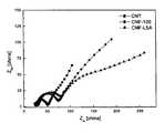
도 14는 3종류의 서로 다른 탄소나노튜브에 대한 CV 측정 결과를 보여주는 도면.14 shows CV measurement results for three different types of carbon nanotubes.
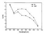
도 15는 종래의 백금전극과 탄소나노튜브의 광파장에 따른 태양전지 효율의 변화를 보여주는 도면.15 is a view showing a change in solar cell efficiency according to the optical wavelength of the conventional platinum electrode and carbon nanotubes.
<도면의 주요 부분에 대한 부호의 설명><Explanation of symbols for the main parts of the drawings>
101...상부 투명기판 102...도전성 투명전극101 ... upper
103...염료가 흡착된 다공질 전극 104...전해질103 Porous electrode with dye adsorbed 104 Electrolyte
105...상대전극(탄소나노튜브막) 106...하부 기판105 Relative electrode (carbon nanotube film) 106 Lower substrate
201...다중벽 탄소나노튜브 202,203...탄소나노섬유201 ... Multi-walled carbon nanotubes 202,203 ... Carbon nanofibers
401...탄소나노튜브 연결전극 또는 그리드 전극401 carbon nanotube connection electrode or grid electrode
501...절연막501 ... insulation film
본 발명은 탄소나노튜브 전극을 이용한 염료감응형 태양전지 모듈에 관한 것으로서, 특히 탄소나노튜브 전극의 높은 전기전도성과 유연성을 이용하여, 광전기화학 작용에 의해 생성된 전자를 포집하는 그리드(gird) 전극과 동일 기판 상에서 2개 이상의 단위 태양전지를 연결하는 연결전극으로 탄소나노튜브 전극을 사용하고, 결합제의 양을 조절하여 탄소나노튜브 페이스트(paste)를 부도체로 만들어 단위 태양전지 간의 화학적, 전기적 절연체 역할을 하는 탄소나노튜브 절연막을 갖는 염료감응형 태양전지 모듈에 관한 것이다.BACKGROUND OF THE INVENTION 1. Field of the Invention The present invention relates to a dye-sensitized solar cell module using a carbon nanotube electrode, and in particular, a grid electrode that captures electrons generated by photoelectrochemical action, utilizing the high electrical conductivity and flexibility of the carbon nanotube electrode. Carbon nanotube electrode is used as a connection electrode for connecting two or more unit solar cells on the same substrate as the non-conductor by controlling the amount of the binder to act as a chemical and electrical insulator between the unit solar cells. It relates to a dye-sensitized solar cell module having a carbon nanotube insulating film.
일반적으로, 염료감응형 태양전지는 염료의 태양광 흡수 능력을 이용하여 화학적으로 발전을 일으키는 태양전지의 일종으로, 유리 기판 위에 음극, 염료, 전해질, 상대전극, 투명 도전성 전극 등을 구비하고 있다. 음극은 나노(nano) 다공질막 의 형태로 존재하는 TiO2, ZnO, SnO2와 같은 넓은 밴드갭을 가진 n형 산화물 반도체로 구성되어 있고, 이 표면에 단분자 층의 염료가 흡착되어 있다. 태양광이 태양전지에 입사되면, 염료 속의 페르미 에너지 부근의 전자가 태양에너지를 흡수하여 전자가 채워지지 않은 상위 준위로 여기된다. 이때 전자가 빠져나간 하위 준위의 빈 자리는 전해질 속의 이온이 전자를 제공함으로써 다시 채워진다. 염료에 전자를 제공한 이온은 양극인 상대전극으로 이동하여 전자를 제공받게 된다. 이때 양극부의 상대전극은 전해질 속에 있는 이온의 산화환원 반응의 촉매로 작용하여 표면에서의 산화환원 반응을 통하여 전해질 속의 이온에 전자를 제공하는 역할을 한다. 이러한 상대전극의 작용을 만족시키기 위하여 종래의 염료감응형 태양전지에서의 상대전극으로는 촉매작용이 우수한 백금박막을 주로 사용하고 있으며, 백금과 특성이 비슷한 팔라듐, 은, 금 등의 귀금속과 카본블랙, 그래파이트와 같은 탄소계 전극을 사용하기도 한다.In general, a dye-sensitized solar cell is a type of solar cell that chemically generates power by utilizing the solar absorption ability of a dye, and includes a cathode, a dye, an electrolyte, a counter electrode, a transparent conductive electrode, and the like on a glass substrate. The cathode is composed of an n-type oxide semiconductor having a wide bandgap such as TiO2 , ZnO, and SnO2 in the form of a nano porous membrane, and a dye of a single molecule layer is adsorbed on this surface. When sunlight enters the solar cell, electrons near the Fermi energy in the dye absorb the solar energy and are excited to an upper level where the electrons are not filled. At this time, the empty position of the lower level where the electrons are released is refilled by the ions in the electrolyte providing the electrons. Ions that provide electrons to the dye move to the counter electrode, which is the anode, to receive electrons. At this time, the counter electrode of the anode serves as a catalyst for the redox reaction of the ions in the electrolyte to provide electrons to the ions in the electrolyte through the redox reaction on the surface. In order to satisfy the action of the counter electrode, a platinum thin film having excellent catalytic action is mainly used as a counter electrode in a conventional dye-sensitized solar cell, and precious metals such as palladium, silver, and gold, which are similar to platinum, and carbon black are used. Carbon-based electrodes such as graphite may also be used.
그런데, 백금전극은 높은 전기전도도와 우수한 촉매특성을 지니고 있으나 가격이 고가이고, 촉매 작용이 일어나는 표면적을 높이는 데 한계가 있어 전지 전체의 촉매 반응속도를 높이는데 한계가 있다. 탄소계 전극의 경우는 가격이 저가이고, 표면적을 백금보다 높이는 것은 가능하나 백금보다 촉매반응 속도가 나쁘기 때문에 태양전지의 효율을 떨어뜨리는 단점이 있다. 이에 따라 모듈이 대면적화하면서 가격이 저렴하면서도, 표면적과 전기전도도가 높은 새로운 촉매 상대전극이 필요하다.By the way, the platinum electrode has high electrical conductivity and excellent catalytic properties, but the price is expensive, and there is a limit in increasing the surface area at which the catalytic action occurs, thereby limiting the catalyst reaction speed of the entire battery. In the case of carbon-based electrodes, the price is low and it is possible to increase the surface area than platinum. However, since the catalytic reaction rate is worse than that of platinum, the efficiency of the solar cell is reduced. As a result, new catalyst counter electrodes are needed, which have a large surface area and low cost, but have high surface area and high electrical conductivity.
또한 기존의 백금 전극의 경우, 기판으로 세라믹과 같은 절연체 기판을 사용하면, 전지가 요구하는 전기전도도를 만족하기 위하여 두꺼운 막으로 제작하여야 하고, 이 경우 고 비용이 들기 때문에, 현실적으로 기판을 절연성 물질로 사용하는 것이 불가능하다.In addition, in the case of the conventional platinum electrode, if an insulator substrate such as ceramic is used as the substrate, it must be made of a thick film to satisfy the electrical conductivity required by the battery, and in this case, it is expensive, so the substrate is made of an insulating material. It is impossible to use.
또한, 태양전지의 모듈을 대면적으로 제작 시, 기존의 백금전극의 경우, 대형 스퍼터링 장치와 같은 고가 장비를 사용하거나, 고가의 백금 화합물을 사용하여 스크린 프린팅방법으로 제작하여야 하므로, 제작 경비의 부담이 커서, 경제성이 낮아지게 된다.In addition, when manufacturing the module of the solar cell in a large area, in the case of the existing platinum electrode, expensive equipment such as a large sputtering device or expensive platinum compound to be produced by the screen printing method, the burden of production costs This is large and economics are low.
한편, 모듈의 전력을 높이기 위해서 대면적으로 염료감응형 태양전지를 제작할 경우, 대면적의 단일 셀로는 높은 효율을 얻기가 사실상 불가능하다. 이 때문에 일반적으로 효율이 높은 대면적 모듈을 제작할 시에는, 복수 개의 단위셀을 연결전극을 사용하여 연결하거나, 단위셀의 내부에 전자를 효율적으로 포집하는 그리드 전극을 삽입한다. 종래에는 그리드 전극이나 연결전극으로 대부분 백금, 은, 금, 니켈과 같은 금속을 사용하고 있다. 이러한 금속계 연결전극은 전해질과의 반응에 의해 용해되거나 반응하므로 엄밀한 절연을 필요로 하여 제조가 어렵고, 플라스틱 기판과 같이 유연성이 요구되는 경우 사용이 힘들다는 단점이 있으며, 제조 비용도 많이 소요되어 대량 생산에 많은 문제점을 지니고 있다. 이에 따라 화학적으로 안정하면서도, 유연성이 있는 신형 전극에 대한 필요성이 대두되고 있다.On the other hand, when manufacturing a dye-sensitized solar cell with a large area in order to increase the power of the module, it is virtually impossible to achieve high efficiency with a large area single cell. For this reason, in general, when manufacturing a large area module having high efficiency, a plurality of unit cells are connected using a connecting electrode, or a grid electrode for efficiently collecting electrons is inserted into the unit cell. Conventionally, metals such as platinum, silver, gold, and nickel are mostly used as grid electrodes or connection electrodes. Since the metal-based connection electrode is dissolved or reacted by the reaction with the electrolyte, it is difficult to manufacture because it requires rigid insulation, and it is difficult to use when flexibility is required, such as a plastic substrate. Has many problems. Accordingly, there is a need for a new electrode that is chemically stable and flexible.
본 발명은 이상과 같은 사항을 감안하여 창출된 것으로서, 탄소나노튜브 전 극의 높은 전기전도성과 유연성을 이용하여, 광전기화학 작용에 의해 생성된 전자를 포집하는 그리드(gird) 전극과 동일 기판 상에서 2개 이상의 단위 태양전지를 연결하는 연결전극으로 탄소나노튜브 전극을 사용하고, 결합제의 양을 조절하여 탄소나노튜브 페이스트(paste)를 부도체로 만들어 단위 태양전지 간에 화학적, 전기적 절연체 역할을 하는 탄소나노튜브 절연막을 형성함으로써 대면적의 태양전지 모듈의 제작 및 전기적, 화학적으로 안정한 모듈의 제작을 가능하게 하는 탄소나노튜브 전극을 이용한 염료감응형 태양전지 모듈을 제공함에 그 목적이 있다.The present invention has been made in view of the above-mentioned matters, and utilizes the high electrical conductivity and flexibility of the carbon nanotube electrode, so that the same electrode on the same substrate as the grid electrode that collects electrons generated by photoelectrochemical action Carbon nanotube electrode is used as a connecting electrode to connect more than two unit solar cells, and carbon nanotubes act as chemical and electrical insulators between unit solar cells by making carbon nanotube paste into non-conductor by controlling the amount of binder. It is an object of the present invention to provide a dye-sensitized solar cell module using a carbon nanotube electrode that enables the fabrication of a large-area solar cell module and the production of an electrically and chemically stable module by forming an insulating film.
상기의 목적을 달성하기 위하여 본 발명의 제1실시예에 따른 탄소나노튜브 전극을 이용한 염료감응형 태양전지 모듈은,Dye-sensitized solar cell module using a carbon nanotube electrode according to a first embodiment of the present invention to achieve the above object,
백금 상대전극을 사용한 단위 염료감응형 태양전지나, 상,하부 투명기판과, 상부 투명기판의 내측 표면에 형성된 도전성 투명전극과, 도전성 투명전극 위에 형성된 것으로 그 표면에는 염료가 흡착된 산화물반도체 다공질 음극전극과, 하부 투명기판 위에 박막형태로 형성된 것으로 상기 음극전극에 대응하는 양극부로서의 탄소나노튜브층으로 된 상대전극과, 상기 음극전극과 상대전극 사이에 충전된 전해질을 구비하는 단위 염료감응형 태양전지를 연결전극 및 그리드 전극을 이용하여 복수개 직렬 또는 병렬로 연결하여 구성된 염료감응형 태양전지 모듈에 있어서,Unit dye-sensitized solar cell using a platinum counter electrode, an upper and lower transparent substrate, a conductive transparent electrode formed on the inner surface of the upper transparent substrate, and an oxide semiconductor porous cathode electrode on which the dye is adsorbed, formed on the conductive transparent electrode. And a counter electrode formed of a thin film on a lower transparent substrate, the counter electrode comprising a carbon nanotube layer serving as an anode part corresponding to the cathode electrode, and an electrolyte charged between the cathode electrode and the counter electrode. In the dye-sensitized solar cell module configured by connecting a plurality of in series or parallel using a connecting electrode and a grid electrode,
상기 연결전극 및 그리드 전극은 탄소나노튜브 전극으로 구성된 점에 그 특징이 있다.The connection electrode and the grid electrode is characterized in that it consists of carbon nanotube electrodes.
여기서, 상기 탄소나노튜브 전극은 탄소나노튜브와 결합제 및 첨가제의 조성 을 조정하여 원하는 전기전도도를 지니게 한 것으로서, 1∼104Ω-1 ㎝-1의 전기전도도를 갖는다.Here, the carbon nanotube electrode is a carbon nanotube and a binding agent and as an additive to adjust the composition of the jinige the desired electrical conductivity, 1~104 Ω-1 ㎝- has an electrical conductivity of1.
또한, 상기의 목적을 달성하기 위하여 본 발명의 제2실시예에 따른 탄소나노튜브 전극을 이용한 염료감응형 태양전지 모듈은,In addition, the dye-sensitized solar cell module using a carbon nanotube electrode according to a second embodiment of the present invention to achieve the above object,
백금 상대전극을 사용한 단위 염료감응형 태양전지나, 상,하부 투명기판과, 상부 투명기판의 내측 표면에 형성된 도전성 투명전극과, 도전성 투명전극 위에 형성된 것으로 그 표면에는 염료가 흡착된 산화물반도체 다공질 음극전극과, 하부 투명기판 위에 박막형태로 형성된 것으로 상기 음극전극에 대응하는 양극부로서의 탄소나노튜브층으로 된 상대전극과, 상기 음극전극과 상대전극 사이에 충전된 전해질을 구비하는 단위 염료감응형 태양전지를 연결전극 및 그리드 전극을 이용하여 복수개 직렬 또는 병렬로 연결하여 구성된 염료감응형 태양전지 모듈에 있어서,Unit dye-sensitized solar cell using a platinum counter electrode, an upper and lower transparent substrate, a conductive transparent electrode formed on the inner surface of the upper transparent substrate, and an oxide semiconductor porous cathode electrode on which the dye is adsorbed, formed on the conductive transparent electrode. And a counter electrode formed of a thin film on a lower transparent substrate, the counter electrode comprising a carbon nanotube layer serving as an anode part corresponding to the cathode electrode, and an electrolyte charged between the cathode electrode and the counter electrode. In the dye-sensitized solar cell module configured by connecting a plurality of in series or parallel using a connecting electrode and a grid electrode,
상기 단위 염료감응형 태양전지들 사이에는 단위 태양전지들 간의 절연을 위한 절연막이 더 형성되는 점에 그 특징이 있다.The unit dye-sensitized solar cells are characterized in that an insulating film for insulating between unit solar cells is further formed.
여기서, 상기 절연막은 바람직하게는 탄소나노튜브 절연막으로 구성된다. 그리고, 그 탄소나노튜브 절연막은 단위 태양전지 간에 직접적인 전기적 연결이 되지 않을 정도의 절연성을 갖도록, 바람직하게는 탄소나노튜브와 결합제 및 첨가제의 혼합물로 구성된다.Here, the insulating film is preferably composed of a carbon nanotube insulating film. In addition, the carbon nanotube insulating film is preferably composed of a mixture of carbon nanotubes, a binder and an additive so as to have an insulation degree such that there is no direct electrical connection between unit solar cells.
이하 첨부된 도면을 참조하면서, 본 발명의 실시예를 상세히 설명한다.Hereinafter, exemplary embodiments of the present invention will be described in detail with reference to the accompanying drawings.
도 1은 본 발명에 따른 탄소나노튜브를 이용한 염료감응형 태양전지 모듈에 채용되는 단위 염료감응형 태양전지의 구조를 개략적으로 보여주는 도면이다.1 is a view schematically showing the structure of a unit dye-sensitized solar cell employed in a dye-sensitized solar cell module using carbon nanotubes according to the present invention.
도 1을 참조하면, 본 발명에 채용되는 탄소나노튜브를 이용한 염료감응형 태양전지는 일반적인 염료감응형 태양전지의 구성을 기본적으로 갖는다. 즉, 유리나 투명 플라스틱으로 된 상부 투명기판(101)과, 상부 투명기판(101)의 내측(도면상으로는 하면부) 표면에 형성된 ITO, SnO2, ZnO 재질의 도전성 투명전극(102)과, 도전성 투명전극(102) 위에(도면상으로는 하면부에) 형성된 것으로 그 표면에는 염료가 흡착된 산화물반도체(예컨대, TiO2, SnO2, ZnO) 다공질 음극전극(103)과, 하부 투명기판(106) 위에 박막형태로 형성된 것으로 상기 다공질 음극전극(103)에 대응하는 양극부로서의 상대전극(105)과, 상기 음극전극(103)과 상대전극(105) 사이에 충전된 전해질(104)(액체전해질이나 고분자겔, p형 반도체로 구성됨)을 기본적으로 구비한다.Referring to FIG. 1, the dye-sensitized solar cell using carbon nanotubes employed in the present invention basically has a configuration of a general dye-sensitized solar cell. That is, the upper
그러나, 본 발명에 채용되는 염료감응형 태양전지에서는 상기 상대전극(105)이 탄소나노튜브층으로 구성되는 점이 종래의 일반적인 염료감응형 태양전지와 다르다. 이와 같이 탄소나노튜브를 사용하는 것은 상대전극(105)의 표면에서의 산화환원 반응을 극대화시키기 위한 것이다. 여기서, 이와 같은 탄소나노튜브층을 이루는 탄소나노튜브로는 단일벽 탄소나노튜브나 도 2에 도시된 바와 같은, 다중벽 탄소나노튜브(201) 또는 탄소나노섬유(202)(203)나, 도 3에 도시된 바와 같은 금속계 탄소나노튜브가 사용될 수 있다. 본 발명에 채용되는 탄소나노튜브 중 특히 우수한 특성을 나타내는 탄소나노튜브는 금속계 탄소나노튜브로서, 도 3에서 볼 수 있는 바와 같이 개개의 탄소나노튜브 가닥들이 화학적으로 결합하여 탄소나노튜브들이 탄소나노튜브 제조 시에 사용된 금속탄화물 촉매들과 함께 섞여서 가지 모양으로 상호 연결되어 있음을 알 수 있다.However, in the dye-sensitized solar cell employed in the present invention, the
도 4 및 도 5는 이상에서와 같은 탄소나노튜브를 이용한 단위 염료감응형 태양전지를 이용하여 제작한 염료감응형 태양전지 모듈을 나타낸 것으로서, 도 4는 본 발명의 제1실시예에 따른 염료감응형 태양전지 모듈을 보여주는 도면이고, 도 5는 본 발명의 제2실시예에 따른 염료감응형 태양전지 모듈을 보여주는 도면이다.4 and 5 shows a dye-sensitized solar cell module manufactured using a unit dye-sensitized solar cell using the carbon nanotubes as described above, Figure 4 is a dye-sensitized according to a first embodiment of the
도 4를 참조하면, 본 발명의 제1실시예에 따른 탄소나노튜브 전극을 이용한 염료감응형 태양전지 모듈은, 백금 상대전극을 사용한 단위 염료감응형 태양전지나, 상,하부 투명기판과, 상부 투명기판의 내측 표면에 형성된 도전성 투명전극과, 도전성 투명전극 위에 형성된 것으로 그 표면에는 염료가 흡착된 산화물반도체 다공질 음극전극과, 하부 투명기판 위에 박막형태로 형성된 것으로 상기 음극전극에 대응하는 양극부로서의 탄소나노튜브층으로 된 상대전극과, 상기 음극전극과 상대전극 사이에 충전된 전해질을 구비하는 단위 염료감응형 태양전지를 연결전극(401) 및 그리드 전극(402)을 이용하여 복수개 직렬 또는 병렬로 연결하여 구성한 것이다.4, a dye-sensitized solar cell module using a carbon nanotube electrode according to the first embodiment of the present invention, a unit dye-sensitized solar cell using a platinum counter electrode, an upper and lower transparent substrate, and an upper transparent A conductive transparent electrode formed on the inner surface of the substrate, an oxide semiconductor porous cathode electrode on which the dye is adsorbed, and a thin film on the lower transparent substrate formed on the surface of the conductive transparent electrode, and carbon as the anode portion corresponding to the cathode electrode; A unit dye-sensitized solar cell having a counter electrode made of a nanotube layer and an electrolyte charged between the cathode electrode and the counter electrode is connected in series or in parallel using a connecting
상기 그리드 전극(402)은 단위 태양전지 내부에서 발생한 전자를 효율적으로 외부로 전달하기 위한 통로 역할을 하고, 상기 연결전극(401)은 단위 태양전지를 태양전지의 제일 바깥쪽에서 연결하는 역할을 한다.The
여기에서, 특히 상기 연결전극(401) 및 그리드 전극(402)은 탄소나노튜브 전 극으로 구성된다. 이 탄소나노튜브 전극은 탄소나노튜브와 결합제 및 첨가제의 조성을 조정하여 원하는 전기전도도를 지니게 한 것으로서, 1∼104Ω-1 ㎝-1의 전기전도도를 갖는다. 이상과 같은 탄소나노튜브 전극을 제조하기 위한 탄소나노튜브 페이스트는 탄소나노튜브와 카본 또는 금속계 첨가제, CMC(carboxyl methyl cellulose) 또는 PVDF와 같은 고분자 결합제를 볼밀, 고에너지볼밀, 초음파, 그라인더, V-mixer를 포함하는 기계적 또는 기계화학적 방법에 의해 혼합하여 제조되며, 상기 결합제의 함량은 0.5∼90중량%의 값을 갖는다. 또한, 상기 탄소나노튜브 페이스트를 이용하여 만든 탄소나노튜브 전극은 닥터블레이드법, 스크린프린팅법, 스프레이법, 스핀코팅법, 페인팅법을 포함하는 막을 제조하는 방법에 의해 점상, 선상, 면상의 패턴으로 제조되고, 그 두께는 100nm∼1mm의 범위에 있으며, 투명에서 불투명까지 제조 가능하다. 특히, 면상으로 제조할 시 스프레이법에 의해 1㎡ 이하의 넓은 면에도 코팅하는 것이 가능하다.Here, in particular, the
도 6은 탄소나노튜브(다중벽 탄소나노튜브)와 CMC 결합제를 사용하여 제조한 탄소나노튜브 전극막의 전자현미경 사진으로서, 탄소나노튜브 전극막은 다공질 상태로 넓은 표면적을 지니고 있음을 알 수 있다.FIG. 6 is an electron micrograph of a carbon nanotube electrode membrane prepared using a carbon nanotube (multi-walled carbon nanotube) and a CMC binder, and it can be seen that the carbon nanotube electrode membrane has a large surface area in a porous state.
여기서, 탄소나노튜브 전극막은 탄소나노튜브 분말과 첨가제를 CMC나 PVDF 등의 적절한 결합제를 물이나 DMP 등의 용매와 혼합하여 페이스트 상으로 만들어서 스크린 프린팅, 닥터블레이드, 스핀 코팅, 스프레이 코팅, 페인팅 등의 방법으로 하부기판 상에 패턴에 따라 코팅함으로써 형성된다.Here, the carbon nanotube electrode film is prepared by mixing carbon nanotube powder and additives with a suitable binder such as CMC or PVDF with a solvent such as water or DMP to form a paste, such as screen printing, doctor blade, spin coating, spray coating and painting. It is formed by coating according to the pattern on the lower substrate in a method.
본 발명에서의 탄소나노튜브 전극막은 표면적을 극대화하기 위하여 결합제의 함량을 0.5%까지 감소시켜 탄소나노튜브 간의 최소한의 결합만을 이루게 하여 다공질 상태로 만들거나, 높은 전기전도도를 얻기 위하여 상대밀도가 100%에 근접하도록 치밀하게 만들 수가 있다. 또한 도 7에서 보는 것과 같이 1㎛ 이하의 극히 얇은 막상으로 제조하여 투명성을 부여하거나, 태양광 에너지를 모두 흡수하기 위하여 1㎛ 이상 1mm 이하의 두께의 박막 또는 후막으로 제조할 수 있다.In the present invention, the carbon nanotube electrode film is made to reduce the content of the binder to 0.5% to maximize the surface area to achieve a minimal bond between the carbon nanotubes to make a porous state, or to obtain a high
탄소나노튜브 전극을 만들기 위한 탄소나노튜브 페이스트의 제조는 일반적인 볼밀, 유성볼밀이나 바이브레이션밀 또는 어트리션밀(attrition mill)과 같은 하이에너지볼밀, V-mixer, 연마기, 스터링(stirring), 초음파 혼합과 같은 기계적 작용을 통하여 원료를 혼합하거나, 기계적 작용과 동시에 화학적 작용을 수반하는 혼합방식에 의해 이루어질 수 있다.The manufacture of carbon nanotube pastes for making carbon nanotube electrodes involves the use of high-energy ball mills, such as ball mills, planetary ball mills, vibration mills or attrition mills, V-mixers, grinding machines, stirring, ultrasonic mixing and Through the same mechanical action may be made by mixing the raw materials, or by a mixing method accompanied by a mechanical action and a chemical action.
혼합방법의 대표적인 예로 볼밀을 이용하여 탄소나노튜브 페이스트를 제조하는 한 예를 들면 다음과 같다. 평균 직경은 10∼20nm, 평균 길이는 5㎛인 탄소나노튜브 분말과 용매로 사용되는 증류수와 결합제로 사용되는 CMC 분말을 10 : 88.5 : 1.5 무게 비로 혼합하여 그라인더나 볼밀을 이용하여 1단계 페이스트를 제조한다. 다음에 혼합된 페이스트를 원형 또는 실린더형의 볼과 함께 볼밀기에 넣어 볼밀기를 회전시키면서 24시간 동안 혼합시켜 균일한 상태의 최종 페이스트로 제조한다. 도 8은 이러한 볼밀 공정을 보여주는 모식도로서, 본 발명과 관련한 실험에서는 실린더형 볼이 구형볼보다 혼합도가 우수함을 알 수 있었다.As a representative example of the mixing method, an example of manufacturing a carbon nanotube paste using a ball mill is as follows. Carbon nanotube powder with an average diameter of 10 to 20 nm and an average length of 5 μm is mixed with distilled water used as a solvent and CMC powder used as a binder in a weight ratio of 10: 88.5: 1.5 to prepare a one-step paste using a grinder or a ball mill. Manufacture. Next, the mixed paste is put into a ball mill with a circular or cylindrical ball and mixed for 24 hours while rotating the ball mill to prepare a final paste in a uniform state. Figure 8 is a schematic diagram showing such a ball mill process, it can be seen in the experiments related to the present invention the cylindrical ball is better mixing than the spherical ball.
본 발명에 채용되는 탄소나노튜브 전극은 전기전도도가 우수하므로, 종래의 태양전지에서 도전성 기판을 사용하여 전극을 형성하는 것과 달리, 투명 전도막이 코팅되어 있는 전도성 유리기판이나 전도성 플라스틱 기판뿐 아니라, 도전성이 없는 유리기판, 알루미나기판을 포함하는 절연성 기판과 PET를 포함하는 플라스틱 기판에도 전극막을 형성할 수 있다. 그 한 예로, 스크린 프린팅법을 이용하여 투명 PET막과 유리기판과 알루미나 기판 위에 20㎛의 두께로 탄소나노튜브 전극막을 코팅하여 100Ω/㎠의 전기전도도를 지닌 전극막을 얻을 수 있었고, 이를 N719 염료를 지닌 염료감응형 태양전지의 상대전극으로 적용하여 8%의 효율을 얻을 수 있었다.Carbon nanotube electrode employed in the present invention is excellent in electrical conductivity, unlike the conventional solar cell using a conductive substrate to form an electrode, as well as conductive glass substrate or conductive plastic substrate coated with a transparent conductive film, conductive Electrode films can also be formed on insulating substrates including glass substrates, alumina substrates, and plastic substrates containing PET. As an example, using a screen printing method, a carbon nanotube electrode film was coated on a transparent PET film, a glass substrate, and an alumina substrate with a thickness of 20 μm to obtain an electrode film having an electrical conductivity of 100 Ω /
한편, 다시 상기 도 5를 참조하면, 본 발명의 제2실시예에 따른 탄소나노튜브 전극을 이용한 염료감응형 태양전지 모듈은, 그 기본 구성에 있어서는 상기 제1실시예의 염료감응형 태양전지 모듈과 동일하다. 다만, 이 제2실시예의 경우에는 상기 단위 염료감응형 태양전지들 사이에 단위 태양전지들 간의 절연을 위한 절연막(501)이 더 형성되는 점에 그 특징이 있다.On the other hand, referring back to Figure 5, the dye-sensitized solar cell module using a carbon nanotube electrode according to a second embodiment of the present invention, in the basic configuration of the dye-sensitized solar cell module of the first embodiment same. However, in the case of the second embodiment, an insulating
여기서, 상기 절연막(501)은 바람직하게는 탄소나노튜브 절연막으로 구성된다. 그리고, 그 탄소나노튜브 절연막은 단위 태양전지 간에 직접적인 전기적 연결이 되지 않을 정도의 절연성을 갖도록, 바람직하게는 탄소나노튜브와 결합제 및 첨가제의 혼합물로 구성된다. 즉, 탄소나노튜브 절연막은 1 kΩcm 이상의 전기저항을 지니도록, 탄소나노튜브에 CMC, PVDF와 같은 부도성 고분자 결합제와 SiO2, TiO2를 포함하는 부도체 무기물의 양이 10% 이상 첨가된 조성을 갖도록 구성된다.Here, the insulating
한편, 도 9는 탄소나노튜브를 지닌 염료감응형 태양전지 소자의 작동 원리를 도식적으로 보여주는 도면이다.On the other hand, Figure 9 is a diagram showing the operating principle of the dye-sensitized solar cell device having a carbon nanotube.
도 9를 참조하면, 태양광이 소자에 입사되면 광감응형 염료(907) 속의 채워진 에너지 궤도에 속하는 전자가 여기되어 전자가 채워지지 않은 빈 궤도로 올라가고, 이 여기 전자는 TiO2 다공질 전극(902)과 도전성 투명전극(901)을 통하여 외부로 이동한다. 한편 광감응 염료(907)에서 전자가 빠져나간 자리는 전해질(906) 속에 있는 이온이 탄소나노튜브(908)와 투명전극(909)으로 구성된 상대전극으로부터 받아온 전자를 전달함으로써 채워진다. 도 9에서 참조번호 900은 상부 투명기판, 903은 TiO2 다공질 전극의 전도대, 904는 TiO2 다공질 전극의 가전도대, 905는 외부의 전기부하, 910은 투명 또는 불투명의 하부기판을 각각 나타낸다.Referring to FIG. 9, when sunlight is incident on the device, electrons belonging to a filled energy orbit in the
도 10은 종래의 백금전극과 탄소나노튜브 전극에 대한 전해질의 산화환원 반응의 CV(cyclic voltametry) 측정 결과를 보여주는 도면이다. 여기에서, CV 측정을 위한 백금 및 탄소나노튜브 전극의 기판으로 FTO를 사용했으며, 상대전극으로 백금판(Pt plate: 2.5×2.5㎠)을 사용하였다.FIG. 10 is a view illustrating CV (cyclic voltametry) measurement results of a redox reaction of an electrolyte for a conventional platinum electrode and a carbon nanotube electrode. Here, FTO was used as a substrate of platinum and carbon nanotube electrodes for CV measurement, and a platinum plate (Pt plate: 2.5 × 2.5 cm 2) was used as a counter electrode.
도 10을 참조하면, 전류의 세기는 곧 전극 반응 속도를 나타내며, J-V 즉, 전류 최고치와 전압 최고치에 의해 형성되는 내부면적은 총 반응량을 의미하는 것으로, 반응 속도가 크고 반응량이 많을수록 환원 반응에 의해 나타나는 결과그래프인 왼쪽 곡선이 그리는 면적이 넓어지고 피크도 커지게 된다. 따라서, 탄소나노튜브(CNT)의 경우가 백금(Pt) 전극에 비해 월등히 우수한 것을 알 수 있다.Referring to FIG. 10, the intensity of the current indicates the electrode reaction rate, and the internal area formed by JV, that is, the current peak and the voltage peak means the total reaction amount. The resulting graph, the left curve, expands the area and draws a larger peak. Therefore, it can be seen that carbon nanotubes (CNT) are much superior to platinum (Pt) electrodes.
도 11은 종래의 백금전극과 탄소나노튜브 전극에 대해 반응이 일어날 수 있 도록 -0.5V의 직류전압을 가한 상태에서 100mHz∼100kHz의 교류전압을 인가하였을 때 나타나는 임피던스 특성을 보여주는 도면이다.FIG. 11 is a diagram illustrating impedance characteristics of a conventional platinum electrode and a carbon nanotube electrode when an alternating voltage of 100 mHz to 100 kHz is applied while a DC voltage of -0.5 V is applied.
도 11을 참조하면, 곡선의 제일 왼쪽에 나타나는 반원이 작을수록 촉매에 의한 산화환원 반응에 대한 전기저항이 작은 것을 의미한다. 탄소나노튜브(CNT)의 경우가 백금(Pt)에 비해 월등히 작은 반응저항을 가지기 때문에 촉매반응이 신속하게 일어날 수 있음을 확인할 수 있다.Referring to FIG. 11, the smaller the semicircle that appears at the far left of the curve, the smaller the electrical resistance to the redox reaction by the catalyst. In the case of carbon nanotubes (CNT) has a much smaller reaction resistance than platinum (Pt) it can be seen that the catalytic reaction can occur quickly.
도 12는 종래의 백금전극과 탄소나노튜브 전극에 대한 안정성 평가를 위해 전해질의 산화환원 반응의 초기 및 15일 경과 후의 CV(cyclic voltametry) 측정 결과를 보여주는 도면이다.FIG. 12 is a view showing CV (cyclic voltametry) measurement results after an initial and 15 days of redox reaction of an electrolyte for stability evaluation of a conventional platinum electrode and a carbon nanotube electrode.
도 12를 참조하면, 백금 전극의 경우 Vpeak는 증가하였지만 Ipeak은 거의 변화가 없으며, 이에 반해, 탄소나노튜브의 경우 Vpeak는 거의 유지되었지만 Ipeak가 눈에 띄게 증가하였음을 알 수 있다.Referring to FIG. 12, in the case of the platinum electrode, Vpeak is increased but Ipeak is almost unchanged. On the other hand, in the case of carbon nanotubes, Vpeak is almost maintained, but Ipeak is noticeably increased.
도 13은 종래의 백금전극과 탄소나노튜브 전극의 안정성 평가를 위해 셀 완성 초기 및 15일 경과 후에 측정된 임피던스 특성을 보여주는 도면이다. 반응이 일어날 수 있도록 -0.5V의 직류전압을 인가하였으며, 100mHz∼100kHz의 주파수 범위 내에서 측정하였다.FIG. 13 is a view showing impedance characteristics measured at the beginning and after 15 days of completion of a cell for evaluating stability of a conventional platinum electrode and a carbon nanotube electrode. A DC voltage of -0.5V was applied to allow a reaction to occur, and the measurement was performed within a frequency range of 100 mHz to 100 kHz.
도 13을 참조하면, CV에서와 같이 백금 전극의 경우 셀 완성 시점으로부터 15일 경과 후 반응저항이 약 67 Ω(ohms)에서 86 Ω으로 증가한 반면, 탄소나노튜브(CNT)의 경우는 약 18 Ω에서 10 Ω으로 감소하는 결과를 보였다.Referring to FIG. 13, the reaction resistance increased from about 67 Ω (ohms) to 86 Ω after 15 days from the completion of the cell in the case of the platinum electrode as in CV, while in the case of carbon nanotubes (CNT), about 18 Ω. The result shows a decrease to 10 Ω at.
도 12와 도 13의 결과로부터, 종래의 백금(Pt)은 누구나 예측되는 열화특성 이 나타났으며, 탄소나노튜브(CNT)는 시간이 지나면서 오히려 촉매 특성 및 전극 저항 특성에서 향상되는 이례적인 결과를 보임을 알 수 있다. 종래의 백금 전극은 전극 반응 과정에서 요오드 이온과의 반응에 의해 착체를 형성하여 표면의 비활성화를 가져오고 백금과 FTO 기판의 부착특성 열화 등으로 인해 결국 태양전지 전체의 효율 감소를 초래한다. 최근 들어, 백금의 이러한 문제를 해결하기 위해 이온전도성이 강하고 휘발성이 강한 아세톤 나이트릴(aceton nitrile) 계의 특수 전해질을 사용하는 움직임을 보이고 있다. 그러나, 이러한 움직임 역시 태양전지의 효율감소의 근원적인 문제를 해결하지 못하고 있는 실정이다. 이러한 관점에서 볼 때, 탄소나노튜브의 CV 및 임피던스 특성은 종래의 백금이 가지는 문제점을 해결하고 나아가 태양전지 효율 향상에 직접적으로 영향을 주어 태양전지 상대전극 재료로서 우수하다는 것을 보여주고 있다.12 and 13, the conventional platinum (Pt) exhibited deterioration characteristics predicted by anyone, and carbon nanotubes (CNT) have an unusual result of improving in catalyst characteristics and electrode resistance characteristics over time. You can see it. Conventional platinum electrodes form complexes by reaction with iodine ions in the electrode reaction process, resulting in deactivation of the surface, and deterioration of adhesion characteristics of platinum and FTO substrates, resulting in reduced efficiency of the entire solar cell. Recently, in order to solve this problem of platinum, there has been a movement to use acetone nitrile-based special electrolytes having strong ion conductivity and high volatility. However, this movement also does not solve the underlying problem of the efficiency reduction of solar cells. From this point of view, the CV and impedance characteristics of the carbon nanotubes solve the problem of the conventional platinum and further show that it is excellent as a solar cell counter electrode material by directly affecting the improvement of solar cell efficiency.
도 14는 3종류의 서로 다른 탄소나노튜브에 대한 임피던스 분광특성을 보여주는 도면이다.FIG. 14 shows impedance spectral characteristics of three different types of carbon nanotubes.
도 14를 참조하면, CV에서와 같이 직경이 작은 탄소나노튜브(CNT)가 가장 낮은 반응저항을 지니고 있어, 태양전지에서 가장 좋은 전극임을 알 수 있다.Referring to FIG. 14, carbon nanotubes (CNTs) having a small diameter as shown in CV have the lowest reaction resistance, and thus, are the best electrodes in a solar cell.
도 15는 종래의 백금전극과 탄소나노튜브의 광파장에 따른 태양전지 효율의 변화를 보여주는 도면이다.15 is a view showing a change in solar cell efficiency according to the optical wavelength of the conventional platinum electrode and carbon nanotubes.
도 15에 도시된 바와 같이, 350nm의 자외선을 제외하고는 거의 전 파장범위에 있어서 탄소나노튜브(CNT) 상대전극을 사용한 태양전지가 백금(Pt)의 경우보다 높은 효율을 지니고 있음을 확인할 수 있다.As shown in FIG. 15, it can be seen that a solar cell using a carbon nanotube (CNT) counter electrode has a higher efficiency than that of platinum (Pt) in almost all wavelength ranges except for 350 nm ultraviolet ray. .
이상의 설명에서와 같이, 본 발명에 따른 탄소나노튜브 전극을 이용한 염료감응형 태양전지 모듈은 상대전극 및 연결전극으로 탄소나노튜브를 사용함으로써, 다음과 같은 장점 및 효과를 갖는다.As described above, the dye-sensitized solar cell module using the carbon nanotube electrode according to the present invention has the following advantages and effects by using carbon nanotubes as the counter electrode and the connecting electrode.
첫째, 탄소나노튜브전극의 촉매 작용을 일으키는 전체 표면적이 종래의 백금전극에 비해 매우 넓음으로써. 높은 산화환원 촉매속도를 지니고 있고, 또한 전기전도도도 우수함으로써, 태양전지 소자 내의 전자전달이 신속히 이루어지게 함으로써, 태양전지의 효율이 향상된다.First, the total surface area that catalyzes the carbon nanotube electrode is much larger than the conventional platinum electrode. By having a high redox catalyst rate and excellent electrical conductivity, the electron transfer in the solar cell element can be performed quickly, thereby improving the efficiency of the solar cell.
둘째, 탄소나노튜브는 금속에 준하는 높은 전기전도도를 지니고 있기 때문에, 종래의 백금 전극의 하부에 필수적으로 사용되는 투명전극을 사용할 필요가 없고, 이에 따라 유리기판이 아닌 다양한 종류의 전기적 절연성이 높은 기판도 사용이 가능하다. 이렇게 하부기판의 종류에 대한 선택의 폭이 넓어지면 유리기판을 사용할 수 없는 경우에도 사용할 수 있고, 다양한 제조 공정을 사용하는 것이 가능하다.Second, since carbon nanotubes have a high electrical conductivity similar to that of metal, it is not necessary to use a transparent electrode that is essentially used under a conventional platinum electrode, and thus various kinds of substrates having high electrical insulation rather than glass substrates. Can also be used. Thus, if the choice of the lower substrate is widened, it can be used even when the glass substrate can not be used, it is possible to use a variety of manufacturing processes.
셋째, 탄소나노튜브막을 기판에 코팅할 때 스크린 프린팅 또는 스프레이법 등을 사용할 수 있어, 대면적의 기판에 균일한 코팅이 가능하다. 이에 따라 대면적의 태양전지를 제작하는 것이 가능하여 넓은 면적의 태양전지의 모듈을 제작할 수 있고, 그 결과 모듈의 가격을 낮추고, 태양전지의 효율을 보다 향상시킬 수 있다.Third, when the carbon nanotube film is coated on the substrate, screen printing or spraying can be used, so that a uniform coating on a large-area substrate is possible. As a result, it is possible to manufacture a large area solar cell, and thus a module of a large area solar cell can be manufactured. As a result, the price of the module can be lowered and the efficiency of the solar cell can be further improved.
넷째, 유연성이 있고, 전기전도성이 있는 탄소나노튜브 전극을 연결전극으로 사용함으로써, 전기적, 화학적으로 안정한 모듈을 제조할 수 있다.Fourth, by using a flexible, electrically conductive carbon nanotube electrode as a connection electrode, it is possible to produce an electrically and chemically stable module.
Claims (7)
Translated fromKoreanPriority Applications (4)
| Application Number | Priority Date | Filing Date | Title |
|---|---|---|---|
| KR1020050115361AKR100654103B1 (en) | 2005-11-30 | 2005-11-30 | Dye-Sensitized Solar Cell Module Using Carbon Nanotube Electrode |
| JP2008511063AJP5028412B2 (en) | 2005-11-30 | 2006-11-30 | Dye-sensitized solar cell module using carbon nanotube electrode and manufacturing method thereof |
| PCT/KR2006/005135WO2007064164A1 (en) | 2005-11-30 | 2006-11-30 | Dye-sensitized solar cell module and the manufacturing method using carbon nanotube electrode |
| US11/871,993US20080264482A1 (en) | 2005-11-30 | 2007-10-13 | Dye-sensitized solar cell module and the manufacturing method using carbon nanotube electrode |
Applications Claiming Priority (1)
| Application Number | Priority Date | Filing Date | Title |
|---|---|---|---|
| KR1020050115361AKR100654103B1 (en) | 2005-11-30 | 2005-11-30 | Dye-Sensitized Solar Cell Module Using Carbon Nanotube Electrode |
Publications (1)
| Publication Number | Publication Date |
|---|---|
| KR100654103B1true KR100654103B1 (en) | 2006-12-06 |
Family
ID=37732158
Family Applications (1)
| Application Number | Title | Priority Date | Filing Date |
|---|---|---|---|
| KR1020050115361AActiveKR100654103B1 (en) | 2005-11-30 | 2005-11-30 | Dye-Sensitized Solar Cell Module Using Carbon Nanotube Electrode |
Country Status (1)
| Country | Link |
|---|---|
| KR (1) | KR100654103B1 (en) |
Cited By (19)
| Publication number | Priority date | Publication date | Assignee | Title |
|---|---|---|---|---|
| KR100928072B1 (en) | 2007-10-05 | 2009-11-23 | 강릉원주대학교산학협력단 | Dye-Sensitized Solar Cell and Manufacturing Method Thereof |
| WO2010024618A3 (en)* | 2008-09-01 | 2010-06-24 | Eagon Window & Door Systems Co., Ltd. | Tile |
| WO2010082794A3 (en)* | 2009-01-19 | 2010-10-21 | 주식회사 티모테크놀로지 | Series/parallel combination type dye-sensitized solar cell module |
| KR101011717B1 (en)* | 2008-09-01 | 2011-01-28 | 삼성전기주식회사 | Electrode of flexible dye-sensitized solar cell, manufacturing method thereof and flexible dye-sensitized solar cell |
| WO2011002231A3 (en)* | 2009-06-30 | 2011-04-14 | 엘지이노텍주식회사 | Solar photovoltaic device |
| KR101030014B1 (en) | 2009-11-09 | 2011-04-20 | 삼성에스디아이 주식회사 | Photoelectric conversion element |
| KR101030013B1 (en) | 2009-08-26 | 2011-04-20 | 삼성에스디아이 주식회사 | Dye-Sensitized Solar Cell |
| KR101081065B1 (en) | 2009-06-30 | 2011-11-07 | 엘지이노텍 주식회사 | Solar cell aparatus |
| KR101084047B1 (en) | 2009-05-08 | 2011-11-16 | 숭실대학교산학협력단 | Nanocomposite dye-sensitized solar cell manufacturing method having photosensitive layer and solar cell |
| KR101091253B1 (en) | 2009-11-03 | 2011-12-07 | 엘지이노텍 주식회사 | Solar cell and manufacturing method thereof |
| KR101097270B1 (en) | 2010-03-25 | 2011-12-21 | 삼성에스디아이 주식회사 | Photoelectric conversion element |
| KR101120361B1 (en) | 2009-05-08 | 2012-03-14 | 숭실대학교산학협력단 | Dye-sensitized Solar Cell and Manufacturing Method Thereof |
| KR101137380B1 (en)* | 2011-03-07 | 2012-04-20 | 삼성에스디아이 주식회사 | Photoelectric conversion device and manufacturing method thereof |
| KR101151936B1 (en) | 2010-07-15 | 2012-06-01 | 주식회사 이건창호 | Dye sensitized solar cell |
| KR101156585B1 (en) | 2009-11-03 | 2012-06-20 | 국립대학법인 울산과학기술대학교 산학협력단 | Dye-sensitized sollar cell and its fabrication method |
| KR101295541B1 (en)* | 2009-05-14 | 2013-08-12 | 엘지전자 주식회사 | Solar cell module and mehtod for manufacturing the same |
| US8728880B2 (en) | 2010-12-17 | 2014-05-20 | Samsung Electronics Co., Ltd. | Graphene electronic device and method of fabricating the same |
| KR101520249B1 (en)* | 2012-11-30 | 2015-05-18 | 한국전기연구원 | Manufacturing Methods of Large Photo-electrochemcal Electrodes Using Hydrothermal Synthesis And Photo-electrode thereof |
| EP2131441A4 (en)* | 2007-03-20 | 2017-11-15 | Sharp Kabushiki Kaisha | Dye-sensitized solar cell module and method for manufacturing the same |
Citations (1)
| Publication number | Priority date | Publication date | Assignee | Title |
|---|---|---|---|---|
| JP2004111216A (en) | 2002-09-18 | 2004-04-08 | Inst Of Research & Innovation | Dye-sensitized solar cells and nanocarbon electrodes |
- 2005
- 2005-11-30KRKR1020050115361Apatent/KR100654103B1/enactiveActive
Patent Citations (1)
| Publication number | Priority date | Publication date | Assignee | Title |
|---|---|---|---|---|
| JP2004111216A (en) | 2002-09-18 | 2004-04-08 | Inst Of Research & Innovation | Dye-sensitized solar cells and nanocarbon electrodes |
Cited By (24)
| Publication number | Priority date | Publication date | Assignee | Title |
|---|---|---|---|---|
| EP2131441A4 (en)* | 2007-03-20 | 2017-11-15 | Sharp Kabushiki Kaisha | Dye-sensitized solar cell module and method for manufacturing the same |
| KR100928072B1 (en) | 2007-10-05 | 2009-11-23 | 강릉원주대학교산학협력단 | Dye-Sensitized Solar Cell and Manufacturing Method Thereof |
| KR101011717B1 (en)* | 2008-09-01 | 2011-01-28 | 삼성전기주식회사 | Electrode of flexible dye-sensitized solar cell, manufacturing method thereof and flexible dye-sensitized solar cell |
| WO2010024618A3 (en)* | 2008-09-01 | 2010-06-24 | Eagon Window & Door Systems Co., Ltd. | Tile |
| KR101002398B1 (en) | 2009-01-19 | 2010-12-21 | (주)다이솔티모 | Direct / parallel mixed dye-sensitized solar cell module |
| WO2010082794A3 (en)* | 2009-01-19 | 2010-10-21 | 주식회사 티모테크놀로지 | Series/parallel combination type dye-sensitized solar cell module |
| KR101120361B1 (en) | 2009-05-08 | 2012-03-14 | 숭실대학교산학협력단 | Dye-sensitized Solar Cell and Manufacturing Method Thereof |
| KR101084047B1 (en) | 2009-05-08 | 2011-11-16 | 숭실대학교산학협력단 | Nanocomposite dye-sensitized solar cell manufacturing method having photosensitive layer and solar cell |
| KR101295541B1 (en)* | 2009-05-14 | 2013-08-12 | 엘지전자 주식회사 | Solar cell module and mehtod for manufacturing the same |
| KR101081065B1 (en) | 2009-06-30 | 2011-11-07 | 엘지이노텍 주식회사 | Solar cell aparatus |
| KR101072073B1 (en) | 2009-06-30 | 2011-10-10 | 엘지이노텍 주식회사 | Solar cell aparatus |
| WO2011002231A3 (en)* | 2009-06-30 | 2011-04-14 | 엘지이노텍주식회사 | Solar photovoltaic device |
| KR101030013B1 (en) | 2009-08-26 | 2011-04-20 | 삼성에스디아이 주식회사 | Dye-Sensitized Solar Cell |
| KR101091253B1 (en) | 2009-11-03 | 2011-12-07 | 엘지이노텍 주식회사 | Solar cell and manufacturing method thereof |
| KR101156585B1 (en) | 2009-11-03 | 2012-06-20 | 국립대학법인 울산과학기술대학교 산학협력단 | Dye-sensitized sollar cell and its fabrication method |
| KR101030014B1 (en) | 2009-11-09 | 2011-04-20 | 삼성에스디아이 주식회사 | Photoelectric conversion element |
| KR101097270B1 (en) | 2010-03-25 | 2011-12-21 | 삼성에스디아이 주식회사 | Photoelectric conversion element |
| US8519261B2 (en) | 2010-03-25 | 2013-08-27 | Samsung Sdi Co., Ltd. | Photoelectric conversion device |
| KR101151936B1 (en) | 2010-07-15 | 2012-06-01 | 주식회사 이건창호 | Dye sensitized solar cell |
| US8728880B2 (en) | 2010-12-17 | 2014-05-20 | Samsung Electronics Co., Ltd. | Graphene electronic device and method of fabricating the same |
| US9257528B2 (en) | 2010-12-17 | 2016-02-09 | Samsung Electronics Co., Ltd. | Graphene electronic device and method of fabricating the same |
| US8592678B2 (en) | 2011-03-07 | 2013-11-26 | Samsung Sdi Co., Ltd. | Photoelectric conversion device and manufacturing method thereof |
| KR101137380B1 (en)* | 2011-03-07 | 2012-04-20 | 삼성에스디아이 주식회사 | Photoelectric conversion device and manufacturing method thereof |
| KR101520249B1 (en)* | 2012-11-30 | 2015-05-18 | 한국전기연구원 | Manufacturing Methods of Large Photo-electrochemcal Electrodes Using Hydrothermal Synthesis And Photo-electrode thereof |
Similar Documents
| Publication | Publication Date | Title |
|---|---|---|
| KR100654103B1 (en) | Dye-Sensitized Solar Cell Module Using Carbon Nanotube Electrode | |
| JP5028412B2 (en) | Dye-sensitized solar cell module using carbon nanotube electrode and manufacturing method thereof | |
| KR100834475B1 (en) | Dye-sensitized solar cell module using carbon nanotube electrode and manufacturing method thereof | |
| KR100783766B1 (en) | Carbon nanotube electrode and manufacturing method thereof and dye-sensitized solar cell | |
| Yan et al. | Noble metal-based materials in high-performance supercapacitors | |
| Liu et al. | Realizing superior electrochemical performance of asymmetric capacitors through tailoring electrode architectures | |
| Ede et al. | One step synthesis of Ni/Ni (OH) 2 nano sheets (NSs) and their application in asymmetric supercapacitors | |
| CN100505323C (en) | Electrode, photoelectric conversion element and dye-sensitized solar cell | |
| Jia et al. | Formation of hierarchical structure composed of (Co/Ni) Mn-LDH nanosheets on MWCNT backbones for efficient electrocatalytic water oxidation | |
| Rafique et al. | Highly uniform anodically deposited film of MnO2 nanoflakes on carbon fibers for flexible and wearable fiber-shaped supercapacitors | |
| Joshi et al. | Nickel incorporated carbon nanotube/nanofiber composites as counter electrodes for dye-sensitized solar cells | |
| You et al. | Designing binary Ru–Sn oxides with optimized performances for the air electrode of rechargeable zinc–air batteries | |
| EP1830431B1 (en) | Counter electrode for photoelectric converter and photoelectric converter | |
| Foo et al. | High-performance supercapacitor based on three-dimensional hierarchical rGO/nickel cobaltite nanostructures as electrode materials | |
| Theerthagiri et al. | Electrochemical deposition of carbon materials incorporated nickel sulfide composite as counter electrode for dye-sensitized solar cells | |
| JP2008021651A (en) | SOLAR CELL USING CARBON NANOTUBE CARRYING CATALYST AND METHOD FOR PRODUCING SAME | |
| CN1846327A (en) | dye-sensitized solar cells | |
| Huang et al. | Solution-processed relatively pure MoS2 nanoparticles in-situ grown on graphite paper as an efficient FTO-free counter electrode for dye-sensitized solar cells | |
| CN101388294A (en) | An all-carbon counter electrode for dye-sensitized solar cells and its preparation method | |
| KR20100114402A (en) | Method for fabrication of conductive film using conductive frame and conductive film | |
| KR20100039136A (en) | Modified carbon nanotube grafted by living polymer, carbon nanotube electrode and dye-sensitized solar cell using the same, and each preparation method thereof | |
| Yan et al. | Preparation of platinum/polyaniline/multi-walled carbon nanotube nanocomposite with sugarcoated haws structure for electrocatalytic oxidation of methanol | |
| Gong et al. | Facile and scalable fabrication of transparent and high performance Pt/reduced graphene oxide hybrid counter electrode for dye-sensitized solar cells | |
| Li et al. | In situ synthesis of oriented NiS nanotube arrays on FTO as high-performance counter electrode for dye-sensitized solar cells | |
| KR100928219B1 (en) | Oil-Based Carbon Nanotube Paste Composition, Oil-Based Carbon Nanotube Electrode Using the Same, Manufacturing Method Thereof, and Dye-Sensitized Solar Cell Using the Oil-Based Carbon Nanotube Electrode |
Legal Events
| Date | Code | Title | Description |
|---|---|---|---|
| A201 | Request for examination | ||
| PA0109 | Patent application | Patent event code:PA01091R01D Comment text:Patent Application Patent event date:20051130 | |
| PA0201 | Request for examination | ||
| E701 | Decision to grant or registration of patent right | ||
| PE0701 | Decision of registration | Patent event code:PE07011S01D Comment text:Decision to Grant Registration Patent event date:20061121 | |
| GRNT | Written decision to grant | ||
| PR0701 | Registration of establishment | Comment text:Registration of Establishment Patent event date:20061129 Patent event code:PR07011E01D | |
| PR1002 | Payment of registration fee | Payment date:20061130 End annual number:3 Start annual number:1 | |
| PG1601 | Publication of registration | ||
| PR1001 | Payment of annual fee | Payment date:20091103 Start annual number:4 End annual number:4 | |
| PR1001 | Payment of annual fee | Payment date:20101110 Start annual number:5 End annual number:5 | |
| PR1001 | Payment of annual fee | Payment date:20111025 Start annual number:6 End annual number:6 | |
| FPAY | Annual fee payment | Payment date:20121107 Year of fee payment:7 | |
| PR1001 | Payment of annual fee | Payment date:20121107 Start annual number:7 End annual number:7 | |
| FPAY | Annual fee payment | Payment date:20131107 Year of fee payment:8 | |
| PR1001 | Payment of annual fee | Payment date:20131107 Start annual number:8 End annual number:8 | |
| FPAY | Annual fee payment | Payment date:20141105 Year of fee payment:9 | |
| PR1001 | Payment of annual fee | Payment date:20141105 Start annual number:9 End annual number:9 | |
| FPAY | Annual fee payment | Payment date:20151112 Year of fee payment:10 | |
| PR1001 | Payment of annual fee | Payment date:20151112 Start annual number:10 End annual number:10 | |
| FPAY | Annual fee payment | Payment date:20161129 Year of fee payment:11 | |
| PR1001 | Payment of annual fee | Payment date:20161129 Start annual number:11 End annual number:11 | |
| FPAY | Annual fee payment | Payment date:20171121 Year of fee payment:12 | |
| PR1001 | Payment of annual fee | Payment date:20171121 Start annual number:12 End annual number:12 | |
| FPAY | Annual fee payment | Payment date:20181126 Year of fee payment:13 | |
| PR1001 | Payment of annual fee | Payment date:20181126 Start annual number:13 End annual number:13 | |
| FPAY | Annual fee payment | Payment date:20191120 Year of fee payment:14 | |
| PR1001 | Payment of annual fee | Payment date:20191120 Start annual number:14 End annual number:14 | |
| PR1001 | Payment of annual fee | Payment date:20211122 Start annual number:16 End annual number:16 | |
| PR1001 | Payment of annual fee | Payment date:20241120 Start annual number:19 End annual number:19 |