KR100651544B1 - Optical-to-wireless link system to accommodate multiple services - Google Patents
Optical-to-wireless link system to accommodate multiple servicesDownload PDFInfo
- Publication number
- KR100651544B1 KR100651544B1KR1020050127761AKR20050127761AKR100651544B1KR 100651544 B1KR100651544 B1KR 100651544B1KR 1020050127761 AKR1020050127761 AKR 1020050127761AKR 20050127761 AKR20050127761 AKR 20050127761AKR 100651544 B1KR100651544 B1KR 100651544B1
- Authority
- KR
- South Korea
- Prior art keywords
- optical
- fdd
- port
- signal
- tdd
- Prior art date
- Legal status (The legal status is an assumption and is not a legal conclusion. Google has not performed a legal analysis and makes no representation as to the accuracy of the status listed.)
- Expired - Fee Related
Links
Images


Classifications
- H—ELECTRICITY
- H04—ELECTRIC COMMUNICATION TECHNIQUE
- H04B—TRANSMISSION
- H04B10/00—Transmission systems employing electromagnetic waves other than radio-waves, e.g. infrared, visible or ultraviolet light, or employing corpuscular radiation, e.g. quantum communication
- H04B10/25—Arrangements specific to fibre transmission
- H04B10/2575—Radio-over-fibre, e.g. radio frequency signal modulated onto an optical carrier
- H04B10/25752—Optical arrangements for wireless networks
- H04B10/25758—Optical arrangements for wireless networks between a central unit and a single remote unit by means of an optical fibre
- H—ELECTRICITY
- H04—ELECTRIC COMMUNICATION TECHNIQUE
- H04B—TRANSMISSION
- H04B10/00—Transmission systems employing electromagnetic waves other than radio-waves, e.g. infrared, visible or ultraviolet light, or employing corpuscular radiation, e.g. quantum communication
- H04B10/25—Arrangements specific to fibre transmission
- H—ELECTRICITY
- H04—ELECTRIC COMMUNICATION TECHNIQUE
- H04H—BROADCAST COMMUNICATION
- H04H20/00—Arrangements for broadcast or for distribution combined with broadcast
- H04H20/65—Arrangements characterised by transmission systems for broadcast
- H04H20/69—Optical systems
- H—ELECTRICITY
- H04—ELECTRIC COMMUNICATION TECHNIQUE
- H04H—BROADCAST COMMUNICATION
- H04H20/00—Arrangements for broadcast or for distribution combined with broadcast
- H04H20/65—Arrangements characterised by transmission systems for broadcast
- H04H20/71—Wireless systems
- H—ELECTRICITY
- H04—ELECTRIC COMMUNICATION TECHNIQUE
- H04W—WIRELESS COMMUNICATION NETWORKS
- H04W88/00—Devices specially adapted for wireless communication networks, e.g. terminals, base stations or access point devices
- H04W88/08—Access point devices
- H04W88/085—Access point devices with remote components
- H—ELECTRICITY
- H04—ELECTRIC COMMUNICATION TECHNIQUE
- H04W—WIRELESS COMMUNICATION NETWORKS
- H04W88/00—Devices specially adapted for wireless communication networks, e.g. terminals, base stations or access point devices
- H04W88/08—Access point devices
- H04W88/10—Access point devices adapted for operation in multiple networks, e.g. multi-mode access points
Landscapes
- Engineering & Computer Science (AREA)
- Signal Processing (AREA)
- Computer Networks & Wireless Communication (AREA)
- Physics & Mathematics (AREA)
- Electromagnetism (AREA)
- Optical Communication System (AREA)
Abstract
Translated fromKoreanDescription
Translated fromKorean도 1은 종래의 다종 서비스를 수용하기 위한 광-무선 링크 시스템의 중앙 기지국과 원격 접속 장치의 일 예시 블록 구성도1 is a block diagram illustrating an example of a central base station and a remote access apparatus of an optical-wireless link system for accommodating a conventional multi-service;
도 2는 종래의 다종 서비스를 수용하기 위한 광-무선 링크 시스템의 중앙 기지국과 원격 접속 장치의 다른 예시 블록 구성도FIG. 2 is another exemplary block diagram of a central base station and a remote access device of an optical-wireless link system for accommodating conventional multi-services. FIG.
도 3은 본 발명의 제1 실시예에 따른 다종 서비스를 수용하는 광-무선 링크 시스템의 중앙 기지국과 원격 접속 장치의 블록 구성도3 is a block diagram of a central base station and a remote access device of an optical-wireless link system for accommodating multiple services according to a first embodiment of the present invention;
도 4a, 4b는 도 3 중 제1, 제2 듀플렉서의 동작을 설명하기 위한 S 파라미터 특성 그래프4A and 4B are S parameter characteristic graphs for explaining the operation of the first and second duplexers in FIG.
도 5는 본 발명의 제2 실시예에 따른 다종 서비스를 수용하는 광-무선 링크 시스템의 중앙 기지국과 원격 접속 장치의 블록 구성도5 is a block diagram of a central base station and a remote access device of an optical-wireless link system for accommodating multiple services according to a second embodiment of the present invention.
도 6은 본 발명의 제3 실시예에 따른 다종 서비스를 수용하는 광-무선 링크 시스템의 중앙 기지국과 원격 접속 장치의 블록 구성도6 is a block diagram of a central base station and a remote access device of an optical-wireless link system for accommodating multiple services according to a third embodiment of the present invention.
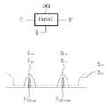
도 7a, 7b, 7c는 도 6 중 다이플렉서와 제1, 제2 듀플렉서의 동작을 설명하기 위한 S 파라미터 특성 그래프7A, 7B, and 7C are S parameter characteristic graphs for explaining the operation of the diplexer and the first and second duplexers in FIG.
도 8은 본 발명의 제4 실시예에 따른 다종 서비스를 수용하는 광-무선 링크 시스템의 중앙 기지국과 원격 접속 장치의 블록 구성도8 is a block diagram of a central base station and a remote access device of an optical-wireless link system for accommodating multiple services according to a fourth embodiment of the present invention.
본 발명은 멀티모드 광섬유를 통해 다양한 서비스 신호를 처리하는 링크 장치 및 그 신호 전송 대역의 설정 방법에 관한 것이다.The present invention relates to a link apparatus for processing various service signals through a multimode optical fiber and a method of setting a signal transmission band thereof.
정보통신 서비스의 다양화와 급속한 증가로 인해 광통신 기술과 무선통신 기술이 결합되어 초고속 무선 멀티미디어 통신 서비스를 제공해야 할 필요성이 증대하고 있다. 이에 유선통신 기술과 무선통신 기술이 결합하여 여러 종류의 대용량 멀티미디어 정보통신 서비스를 가능하게 하도록 초고주파를 초고속 광통신망에 연동시키는 기술에 관심이 집중되고 있으며, 두 기술의 융합에 따른 통합 기술 즉, 고속 전송을 위해 광통신 기술과 이동성을 위한 무선 기술을 동시에 사용하는 광-무선(ROF: Radio Over Fiber) 기술이 활발히 연구되고 있다.Due to the diversification and rapid increase in information communication services, the necessity of providing optical high speed wireless multimedia communication services by combining optical communication technology and wireless communication technology is increasing. Therefore, attention is being focused on the technology of linking the high frequency to the high speed optical communication network to enable various kinds of large capacity multimedia information communication services by combining wired communication technology and wireless communication technology. Radio over fiber (ROF) technology, which uses both optical communication technology and mobile wireless technology for transmission, is being actively researched.
이러한 ROF 기술은 전송 신호를 마이크로파 대역으로 변조하고 이후 광신호로 변환하여 광섬유를 통해 전송하는 광링크 장치와, 광섬유를 통해 수신된 신호를 무선으로 전달하는 무선링크 장치 등이 기본 구성 요소가 되며, 광대역의 요구와 광통신 및 무선통신의 특성을 고려하여 음성, 방송, 데이터 등을 위한 다양한 무선 서비스들을 효율적으로 제공하기 위해 활발한 연구가 진행되고 있다. 이때 음성, 방송, 데이터 등을 이한 다양한 종류의 무선 서비스가 제공되는 환경에서 매 서비 스 마다 원격(remote) 안테나 링크를 구성하는 것은 비효율적이다. 이에 ROF 링크 기술은 여러 종류의 서비스 시스템의 공용화를 통해서 하나의 링크에 여러 무선 서비스들을 동시에 전송하도록 하여 효율성을 높인다.The ROF technology is an optical link device that modulates a transmission signal into a microwave band and then converts the signal into an optical signal and transmits the optical signal, and a wireless link device that wirelessly transmits a signal received through the optical fiber. Active research is being conducted to efficiently provide various wireless services for voice, broadcasting, data, etc. in consideration of the needs of broadband and characteristics of optical communication and wireless communication. At this time, it is inefficient to configure a remote antenna link for each service in an environment in which various kinds of wireless services such as voice, broadcast, and data are provided. ROF link technology improves efficiency by transmitting several wireless services simultaneously on one link through the common use of several types of service systems.
무선통신 시스템 들은 상향 링크와 하향 링크를 구별하는 듀플렉싱(duplexing) 방식으로 주파수를 다르게 하는 주파수분할다중(FDD: Frequency Division Duplexing)과 전송 시간을 다르게 하는 시분할다중(TDD: Time Domain Duplexing) 방식이 사용된다. 이러한 서로 다른 듀플렉싱(TDD/FDD) 방식을 사용하는 무선통신 시스템 공동 기지국이나 인빌딩 솔루션을 위해서 새로운 구조의 RF 종단장치(front-end)가 필요하다.In wireless communication systems, frequency division duplexing (FDD) and frequency division duplexing (TDD) are used. Used. A new RF front-end is required for a common base station or in-building solution for a wireless communication system using these different duplexing (TDD / FDD) schemes.
TDD와 FDD 시스템을 동시에 수용하는 RF 종단장치는 기지국이나 인빌딩 시스템을 공용화 할 경우 시스템 크기를 줄일 수 있고, 증폭기나 안테나를 공유함으로써, 시스템의 비용을 낮출 수 있다. 이러한 RF 종단장치로의 무선 신호의 전송을 위해 ROF 기술이 사용된다.RF terminators that simultaneously accommodate TDD and FDD systems can reduce system size when sharing base stations or in-building systems, and can reduce system costs by sharing amplifiers or antennas. ROF technology is used for the transmission of radio signals to these RF terminators.
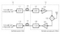
도 1은 종래의 다종 서비스를 수용하기 위한 광-무선 링크 시스템의 중앙 기지국(CS: Central Station)(11)과 원격 접속 장치(RAU: Remote Access Unit)(12)의 일 예시 블록 구성도로서, 종래의 TDD와 FDD 시스템을 동시에 수용할 수 있는 종단장치를 가지는 ROF 링크 구조가 도시된다. TDD 시스템은 시간대역으로 하향과 상향 링크를 구별하고, FDD 시스템은 주파수대역으로 하향과 상향 링크를 구별하므로, TDD와 FDD 신호들이 다중화된 신호를 스위치나 필터 등으로는 하향과 상향을 구별하기가 어려우며, 하기 도 1에서는 서큘레이터 등을 이용해서 하향 신호와 상향 신 호를 구별하는 방식을 채용한다.1 is an exemplary block diagram of a central station (CS) 11 and a remote access unit (RAU) 12 of an optical-wireless link system for accommodating various types of services. An ROF link structure is shown with terminations capable of accommodating conventional TDD and FDD systems simultaneously. Since the TDD system distinguishes the downlink and the uplink by the time band, and the FDD system distinguishes the downlink and the uplink by the frequency band, it is difficult to distinguish the downlink and the uplink signal from the multiplexed TDD and FDD signals by a switch or a filter. In FIG. 1, a method of distinguishing a downlink signal from an uplink signal using a circulator or the like is employed.
도 1을 참조하면, CS(11)는 TDD 및 FDD 신호들이 다중화된 하향 신호를 광신호로 변환하여 하향 광섬유(13)를 통해 RAU(12)로 전송하기 위한 전광 변환기(111)와, RAU(12)로부터 상향 광섬유(14)를 통해 전송된 상향 광신호를 전기적 신호(RF 신호)로 변환하기 위한 광전 변환기(112)를 구비한다. RAU(12)는 CS(11)로부터 전송된 하향 광신호를 전기적인 신호로 변환하기 위한 광전 변환기(121)와, 광전 변환기(121)에서 출력된 하향 신호를 증폭하는 하향 증폭기(HPA: High power amplifier)(122)와, 하향 증폭기(122)에서 증폭된 신호를 안테나로 송출되도록 하며, 안테나에서 수신된 신호를 상향 증폭기(LNA: Low Noise Amplifier)(125)로 제공되도록 신호 경로를 설정하는 서큘레이터(123)와, 서큘레이터(123)에서 제공된 신호를 증폭하는 상향 증폭기(125)와, 상향 증폭기(125)에서 출력된 신호를 광신호로 변환하여 상향 광섬유(14)를 통해 CS(11)로 전송하는 전광 변환기(126)로 구성된다.Referring to FIG. 1, the
상기 도 1의 구조에서, 서큘레이터(124)는 1번 포트로 들어온 하향 링크 입력신호를 2번 포트로 출력시키고, 2번 포트로 입력된 상향 링크 신호는 3번 포트로 출력시키므로, 하향 및 상향 링크를 분리하게 된다. 그런데, 전기적인 서큘레이터를 사용할 경우 서큘레이터의 분리도가 크지 않기 때문에 1번 포트로 들어온 하향 링크의 신호 일부가 3번 포트로 출력될 수 있다. 또한 안테나와 서큘레이터가 완벽한 임피던스 정합이 되어 있지 않을 경우 하향 링크 신호의 일부가 안테나에서 반사되어 2번 포트의 입력이 되어 3번 포트로 출력될 수 있다. 일반적으로, 공기 중 에서의 손실이 크기 때문에 안테나로 들어오는 상향 링크 신호는 매우 작다. 이에 따라 3번 포트로 출력되는 하향 링크가 상향 링크 신호에 비해 크게 되고, 상향 링크를 구성하는 증폭기를 포화(saturation)시켜 하향 링크 성능을 열화시킬 수 있다.In the structure of FIG. 1, the circulator 124 outputs a downlink input signal input to
상향 링크로 흘러 들어가는 FDD 하향 링크 신호는 대역저지 필터(Band stop filter)를 사용하여 작게 할 수 있다. 이러한 경우에도 상향 링크로 흘러 들어가는 TDD 하향 링크 신호는 줄일 수 없기 때문에 TDD 와 FDD 시스템 상향 링크에 모두에 영향을 미치게 된다.The FDD downlink signal flowing into the uplink can be reduced by using a band stop filter. Even in this case, since the TDD downlink signal flowing to the uplink cannot be reduced, it affects both the TDD and the FDD system uplink.
또한, 상기 도 1에 도시된 구조에서, 하향 링크의 경우, TDD 하향 신호와 FDD 하향 신호는 CS의 전광 변환기에서 광신호로 바뀌고, 광섬유를 통해 전송된다. 전송된 신호는 RAU의 광전 변환기에서 RF 신호로 바뀌고 증폭기, 서큘레이터와 안테나를 지나 공기 중으로 방사된다. 상향 링크의 경우에는 RAU의 안테나로 입력된 상향 신호가 서큘레이터와 증폭기를 거쳐 전광 변환기에서 광신호로 바뀌고 광섬유를 통해 전송된다. 전송된 신호는 CS의 광전 변환기에서 RF 신호로 바뀐다. 이러한 ROF 링크에서는 전광 변환기의 비선형 현상이 전체 시스템에 영향을 많이 주게 된다. 서큘레이터를 사용하는 RF 종단장치에서 상향 링크로 흘러 들어오는 하향 링크 신호는 저잡음 증폭기뿐만 아니라 전광 변환기를 포화시키거나 동작전류가 임계(threshold) 전류 보다 낮은 곳에서 동작시켜서 상향 링크 성능을 크게 열화시킬 수 있다.In addition, in the structure shown in FIG. 1, in the downlink, the TDD downlink signal and the FDD downlink signal are converted into an optical signal in the all-optical converter of the CS and transmitted through an optical fiber. The transmitted signal is converted into an RF signal by the RAU's photoelectric converter and radiated into the air past the amplifier, circulator and antenna. In the case of the uplink, an uplink signal input to the antenna of the RAU is converted into an optical signal from an all-optical converter through a circulator and an amplifier and transmitted through an optical fiber. The transmitted signal is converted into an RF signal in the CS photoelectric converter. In these ROF links, the non-linear phenomena of the all-optical converter affect the entire system. In RF terminators that use circulators, the downlink signal flowing into the uplink can significantly degrade uplink performance by saturating all-optical converters, as well as low-noise amplifiers, or by operating at lower than current thresholds. have.
도 2는 종래의 다종 서비스를 수용하기 위한 광-무선 링크 시스템의 CS중앙 기지국과 원격 접속 장치의 다른 예시 블록 구성도로서, 도 2에 도시된 시스템은 TDD 하향 신호가 상향 신호의 영향을 제거하기 위해 CS(21)에서 TDD 신호의 상하향 제어 정보를 RAU(22)로 전송하여 이를 바탕으로 RAU(22)에서 스위치(223)를 이용하여 상하향 TDD 신호를 분리하는 구조를 가진다. 즉, 도 2에 도시된 CS(21)는 도 1에 도시된 CS(11)와 거의 유사한 구조를 가지지만, 전광 변환기(211)에서는 TDD 및 FDD 신호들과 더불어 TDD 신호의 상하향 제어 정보를 전송하기 위한 제어 신호를 다중화하여 하향 광섬유(23)를 통해 RAU(22)로 전송한다. RAU(22)에서는 광전 변환기(221)를 통해 수신된 하향 신호에서 상기 제어 신호를 분리하는 역중화기(224)가 구비되며, 분리된 제어 신호는 제어기(229)로 제공된다. 또한 역다중화기(224)와 하향 증폭기(222)를 거친 하향 신호는 제1듀플렉서(225)로 입력되며, 제1듀플렉서(225)는 하향 신호에서 TDD 하향 신호와 FDD 하향 신호를 분리하여 TDD 신호는 스위치(223)로 제공하며 FDD 신호는 트리플렉서(228)로 제공한다. 트리플렉서(228)는 스위치(223)를 거쳐 제공된 TDD 하향 신호와 제1듀플렉서(225)로부터 제공된 FDD 하향 신호를 안테나로 출력하며, 안테나로부터 입력되는 상향 신호를 FDD 상향 신호와 TDD 상향 신호로 분리하여 TDD 신호는 스위치(223)로 제공하며, FDD 신호는 제2듀플렉서(227)로 제공한다. 제2듀플렉서(227)는 스위치(223)에서 제공된 TDD 상향 신호와 트리플렉서(228)에서 제공된 FDD 상향 신호를 결합하여 상향 증폭기(227)로 제공한다. 이때 상기 제어기(229)는 상기 제어 신호에 따라 스위치(223)가 제1듀플렉서(225)로부터 제공된 TDD 하향 신호를 트리플렉서(228)로 제공하거나 트리플렉서(228)로부터 제공된 TDD 상향 신호를 제2듀플렉서(227)로 제공하도록 스위 칭 동작을 제어한다.FIG. 2 is another exemplary block diagram of a CS central base station and a remote access apparatus of an optical-wireless link system for accommodating conventional multi-services. FIG. To this end, the
이러한 구성을 가지므로, 도 2에 도시된 시스템은 TDD 하향 신호가 상향 신호의 영향을 제거하는 구성을 가지지만, 이를 위해서 별도의 제어 신호를 생성해야 하며 이를 전송하기 위해 별도의 채널을 할당해야 하는 문제점이 있다.With this configuration, the system shown in FIG. 2 has a configuration in which the TDD downlink signal removes the influence of the uplink signal, but for this purpose, a separate control signal must be generated and a separate channel must be allocated to transmit the uplink signal. There is a problem.
따라서, 본 발명의 목적은 RAU단에서 TDD 하향 신호와 FDD 상향 신호를 분리시켜 TDD 하향 신호의 영향을 제거하고, TDD 하향 신호와 FDD 하향 신호뿐만 아니라 방송 신호도 함께 전송할 수 있도록 하기 위한 다종 서비스를 수용하는 ROF 링크 시스템을 제공함에 있다.Accordingly, an object of the present invention is to separate the TDD downlink signal and the FDD uplink signal in the RAU stage to remove the influence of the TDD downlink signal, and to provide various services for transmitting not only the TDD downlink signal and the FDD downlink signal but also the broadcast signal together. To provide a ROF link system that accommodates.
상기한 목적을 달성하기 위하여 본 발명은 다종 서비스를 수용하는 광-무선 링크 시스템에 있어서, TDD(Time Domain Duplexing), FDD(Frequency Division Duplexing) 및 방송 서비스를 수행하며, TDD 하향 신호 및 FDD/방송 하향 신호를 각각 광신호로 변환하여 원격 접속 장치로 전송하며, 상기 원격 접속 장치로부터 광신호로 전송된 TDD 상향 신호 및 FDD 상향 신호를 각각 전기적 신호로 변환하며, 상향, 하향 신호의 분리를 위해 광서큘레이터를 사용하는 중앙기지국과; 상기 중앙기지국에서 전송된 상기 TDD 하향 신호 및 FDD/방송 하향 신호를 각각 전기적 신호로 변환하며, 상기 중앙기지국으로 전송될 TDD 상향 신호 및 FDD 상향 신호를 각각 광신호로 변환하며, 상향, 하향 신호의 분리를 위해 광서큘레이터를 사용하는 원격 접속 장치를 포함하며, 상기 원격 접속 장치는 상기 전기적 신호로 변환된 TDD 하 향 신호 및 FDD/방송 하향 신호를 안테나로 무선 송출하며 무선 수신된 TDD 상향 신호와 FDD 상향 신호를 분리하는 다수의 신호여과/분리/합성기를 구비함을 특징으로 한다.In order to achieve the above object, the present invention provides a TDD (Time Domain Duplexing), FDD (Frequency Division Duplexing) and a broadcast service in an optical-wireless link system that accommodates multiple services, and performs TDD downlink signal and FDD / broadcasting. The downlink signal is converted into an optical signal and transmitted to the remote access device, and the TDD uplink signal and the FDD uplink signal transmitted as the optical signal from the remote access device are converted into electrical signals, respectively. A central base station using a curator; The TDD downlink signal and the FDD / broadcast downlink signal transmitted from the central base station are converted into electrical signals, respectively, and the TDD uplink signal and the FDD uplink signal to be transmitted to the central base station are converted into optical signals, respectively. And a remote access device using an optical circulator for separation, wherein the remote access device wirelessly transmits a TDD down signal and an FDD / broadcast down signal converted into the electrical signal to an antenna, And a plurality of signal filters / separators / synthesizers for separating FDD uplink signals.
이하 본 발명에 따른 바람직한 실시예를 첨부한 도면을 참조하여 상세히 설명한다. 하기 설명에서는 구체적인 구성 소자 등과 같은 특정 사항들이 나타나고 있는데 이는 본 발명의 보다 전반적인 이해를 돕기 위해서 제공된 것일 뿐 이러한 특정 사항들이 본 발명의 범위 내에서 소정의 변형이나 혹은 변경이 이루어질 수 있음은 이 기술분야에서 통상의 지식을 가진 자에게는 자명하다 할 것이다.Hereinafter, exemplary embodiments of the present invention will be described in detail with reference to the accompanying drawings. In the following description, specific details such as specific components are shown, which are provided to help a more general understanding of the present invention, and it is understood that these specific details may be changed or changed within the scope of the present invention. It is self-evident to those of ordinary knowledge in Esau.
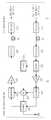
도 3은 본 발명의 제1 실시예에 따른 다종 서비스를 수용하는 광-무선 링크 시스템의 중앙 기지국과 원격 접속 장치의 블록 구성도이다. 도 3을 참조하면, 본 발명의 제1 실시예에 따른 ROF 시스템에서 중앙기지국(CAP: Central Access Platform)(31)은 TDD 방식의 서비스 수행을 위해 TDD 상향, 하향 신호를 처리하는 TDD 서비스부(310)와, FDD 방식의 서비스 수행을 위해 FDD 상향, 하향 신호를 처리하는 FDD 서비스부(320) 및 방송 서비스를 수행하기 위해 상향, 하향 방송 신호를 처리하는 방송 서비스부(322)를 구비한다. 주지한 바와 같이, TDD 상향, 하향 신호는 동일한 주파수 대역(fTDD)을 가지며, FDD 상향 신호와 하향 신호는 서로 다른 주파수 대역(fFDD,up, fFDD,down)을 가진다. 물론 FDD 상향, 하향 주파수 대역은 상기 TDD 주파수 대역과도 구별된다. 또한 본 발명에 따른 방송 서비스를 위해 방 송 신호(하향 신호)의 대역(fBroad)도 별도로 마련된다.3 is a block diagram of a central base station and a remote access apparatus of an optical-wireless link system for accommodating multiple services according to a first embodiment of the present invention. Referring to FIG. 3, in a ROF system according to a first embodiment of the present invention, a central access station (CAP) 31 may include a TDD service unit that processes TDD uplink and downlink signals to perform a TDD service. 310, an
본 발명에서는 TDD 서비스부(310)와 FDD 서비스부(320)는 상호간의 신호 영향을 최소화하기 위해 각각 별도의 광송수신부를 구비한다. 즉 CAP(31)의 TDD 서비스부(310)에서 출력되는 TDD 하향 신호는 제1광송신기(315)에서 전광 변환되어 출력되어 제1광서큘레이터(317) 및 제1광섬유(35)를 거쳐 원격 접속 장치(RAU: Remote Access Unit)(33)로 전송되며, 제1광섬유(35) 및 제1광서큘레이터(317)를 거쳐 RAU(63)에서 제공되는 TDD 상향 신호는 제1광수신기(314)에서 광전 변환된다. 상기에서 제1광서큘레이터(317)는 상기 제1광송신기(315)에서 출력된 TDD 하향 신호를 1번 포트로 입력받아 2번 포트로 출력하여 제1광섬유(35)를 통해 전송되도록 하며, 제1광섬유(35)를 통해 2번 포트로 입력된 TDD 상향 신호를 3번 포트로 출력하여 제1광수신기(314)로 제공되도록 한다.In the present invention, the
CAP(31)의 FDD 서비스부(320)에서 출력되는 FDD 하향 신호는 제1컴바이너(323)에서 방송 신호와 결합되어 제2광송신기(325)에 제공되며, 제2광송신기(325)는 이를 전광 변환하여 제2광서큘레이터(327)로 출력하여 이를 거쳐 제2광섬유(36)를 통해 RAU(63)로 전송되도록 한다. 제2광섬유(36) 및 제2광서큘레이터(327)를 거쳐 RAU(63)에서 제공되는 FDD 상향 신호는 제2광수신기(324)에서 광전 변환되어 FDD 서비스부(320)로 출력된다. 상기에서 제2광서큘레이터(327)는 상기 제2광송신기(325)에서 출력된 FDD/방송 하향 신호를 1번 포트로 입력받아 2번 포트로 출력하여 제2광섬유(36)를 통해 전송되도록 하며, 제2광섬유(36)를 통해 2번 포트로 입력된 FDD 상향 신호를 3번 포트로 출력하여 제2광수신기(324)로 제공되도록 한다.The FDD downlink signal output from the
RAU(63)는 상기 CAP(31)에서 제1광섬유(35)를 통해 전송된 TDD 하향 신호를 2번 포트로 입력받아 이를 3번 포트로 출력하여 제3광수신기(334)로 전송하며, 제3광송신기(335)에서 출력된 TDD 상향 신호를 1번 포트로 입력받아 이를 2번 포트로 출력하여 상기 제1광섬유(35)를 통해 CAP(31)로 전송하는 제3광서큘레이터(337)를 구비한다. 제3광수신기(334)는 제3광서큘레이터(337)에서 제공된 TDD 하향 신호를 광전 변환하여 제1하향증폭기(331)로 출력하며, 제1하향증폭기(331)는 이를 적절히 증폭하여 제2컴바이너(338)를 통해 제1듀플렉서(638)의 1번 포트로 출력되도록 한다. 이때 상기 제1하향증폭기(331)는 HPA(High power amplifier)로 구성될 수 있다. 제1듀플렉서(638)는 이러한 TDD 하향 신호를 2번 포트와 연결된 안테나로 송출하며, 안테나로부터 수신된 TDD 상향 신호를 상기 제2컴바이너(338)로 출력하여 이를 거쳐 제1상향증폭기(332)로 제공되도록 한다. 제1상향증폭기(332)는 이러한 TDD 상향 신호를 적절히 증폭하여 제3광송신기(335)로 제공하며 제3광송신기(335)는 이를 전광 변환하여 제3광서큘레이터(337)로 출력한다. 이때 상기 제1상향증폭기(332)는 LNA(Low Noise Amplifier)(125)로 구성될 수 있다.The
또한, RAU(63)에서는 상기 CAP(31)에서 제2광섬유(36)를 통해 전송된 FDD/방송 하향 신호를 2번 포트로 입력받아 이를 3번 포트로 출력하여 제4광수신기(344)로 전송하며, 제4광송신기(345)에서 출력된 FDD 상향 신호를 1번 포트로 입력받아 이를 2번 포트로 출력하여 상기 제2광섬유(36)를 통해 CAP(31)로 전송하는 제4광서큘레이터(347)를 구비한다. 제4광수신기(344)는 제4광서큘레이터(347)에서 제공된 FDD/방송 하향 신호를 광전 변환하여 제2하향증폭기(341)로 출력하며, 제2하향증폭 기(341)는 이를 적절히 증폭하여 제2듀플렉서(639)의 1번 포트로 출력한다.In addition, the
제2듀플렉서(639)는 제2하향증폭기(341)로부터 제공된 FDD/방송 하향 신호를 2번 포트를 통해 상기 제1듀플렉서(638)의 3번 포트로 출력하며, 제1듀플렉서(638)로부터 2번 포트로 입력되는 FDD 상향 신호를 3번 포트를 통해 제2상향증폭기(342)로 제공되도록 한다. 제2상향증폭기(342)는 이러한 FDD 상향 신호를 적절히 증폭하여 제4광송신기(345)로 제공하며 제4광송신기(345)는 이를 전광 변환하여 제4광서큘레이터(347)로 출력한다.The
상기에서, 제1듀플렉서(638)는 3번 포트로 입력되는 FDD/방송 하향 신호를 2번 포트와 연결된 안테나로 송출하며, 안테나로부터 수신되는 TDD 상향 신호와 FDD 상향 신호를 분리하여 각각 1번 및 3번 포트를 통해 출력한다. 또한 안테나는 FDD 신호 대역과 TDD 신호 대역 및 방송 신호 대역의 신호를 모두 송수신 하기 위해 광대역 안테나로 구성된다.In the above, the
도 4a, 4b는 각각 도 3 중 신호여과/분리/합성기로 통칭할 수 있는, 제1, 제2듀플렉서(638, 639)의 동작을 설명하기 위한 S 파라미터 특성 그래프이다. 먼저 도 4a를 참조하면, 제1듀플렉서(638)는 1번 포트로 입력된 TDD 하향 신호와 3번 포트로 입력된 FDD/방송 하향 신호를 2번 포트를 통해 안테나로 송출하거나, 안테나로부터 2번 포트를 통해 입력된 FDD, TDD 상향 신호를 분리하여 TDD 상향 신호는 상기 1번 포트로 출력하며 FDD 상향 신호는 3번 포트로 출력한다. 이를 위해 도 4a에 도시된 바와 같이, 1, 2번 포트간은 TDD 신호 대역(fTDD) 부분만을 통과시키도록 필터링하며, 2, 3번 포트간은 방송 신호 대역(fBroad)과 FDD 상향, 하향 신호 대역(fFDD) 부분만을 통과시키도록 필터링한다. 또한 1, 3번 포트간은 TDD 신호 대역(fTDD), FDD 상향, 하향 신호 대역(fFDD) 및 방송 신호 대역(fBroad)을 차단하도록 구성된다.4A and 4B are S parameter characteristic graphs for explaining the operation of the first and
도 4b 참조하면, 제2듀플렉서(639)는 1번 포트로 입력된 FDD/방송 하향 신호를 2번 포트를 통해 제1듀플렉서(638)로 출력하거나, 제1듀플렉서(638)로부터 2번 포트를 통해 입력된 FDD 상향 신호를 3번 포트로 출력하는데, 이를 위해 도 4b에 도시된 바와 같이, 1, 2번 포트간은 FDD 하향 신호 대역(fFDD,down)과 방송 신호 대역(fBroad) 부분만을 통과시키도록 필터링하며, 2, 3번 포트간은 FDD 상향 신호 대역(fFDD,up)만을 통과시키도록 필터링한다. 또한 1, 3번 포트간은 FDD 신호 대역과 방송 신호 대역을 모두 차단하도록 구성된다.Referring to FIG. 4B, the
상기 도 3 및 도 4a~4b에 도시된 바와 같은 구성을 가지는 본 발명의 제1 실시예에 따른 시스템의 동작을 살펴보면, 먼저 RF 종단장치가 구비된 RAU(63)에서는 CAP(31)로부터 전송된 TDD 하향 신호는 제3광서큘레이터(337)를 거쳐 제3광수신기(334)에 입력되어 광전 변환되고, 이후 제1하향증폭기(331)에서 증폭된 후, 제1듀플렉서(638)를 통해 안테나로 송출된다. 또한 FDD 하향 신호와 방송 신호는 제4광서큘레이터(347)를 거쳐 제4광수신기(344)에 입력되어 광전 변환되고, 이후 제2하향증폭기(341)에서 증폭된 후, 제2듀플렉서(639) 및 제1듀플렉서(638)를 통해 안테나로 송출된다.Referring to the operation of the system according to the first embodiment of the present invention having the configuration as shown in FIGS. 3 and 4A to 4B, first, the
TDD 상향 신호는 안테나를 통해 수신된 후 제1듀플렉서(339)와, 제1상향증폭기(332)를 거친 후 제3광송신기(335)에서 광신호로 변환되어 제3광서큘레이터(337) 를 통해 제1광섬유(35)로 송출된다. 또한 FDD 상향 신호의 경우 안테나를 통해 수신된 후 제2듀플렉서(639)와 제2상향증폭기(342)를 거친 후 제4광송신기(345)에서 광신호로 변환되어 제4광서큘레이터(347)를 통해 제2광섬유(36)로 송출된다.The TDD uplink signal is received through the antenna and then passed through the
CAP(31)에서는, RAU(63)에서 전송된 TDD 상향 신호가 제1광서큘레이터(317)를 통해 제1광수신기(314)에 입력되어 광전 변환된 후 TDD 서비스부(310)에 제공되며, FDD 상향 신호는 제2광서큘레이터(327)를 통해 제2광수신기(324)에 입력되어 광전 변환된 후 FDD 서비스부(320)에 제공된다. TDD 하향 신호는 제1광송신기(315)에서 광선호로 변환된 후 제1광서큘레이터(317)를 통해서 RAU(63)측으로 전송되며, FDD 하향 신호와 방송 신호는 제2광송신기(325)를 통해 광신호로 변환된 후 제2광서큘레이터(327)를 통해서 RAU(63)측으로 전송된다.In the
이러한 구성 및 동작을 가질 수 있는 본 발명의 시스템은 상하향 신호들을 통상의 전기적인 서큘레이터가 아니라 아이솔레이션이 매우 높은 광서큘레이터를 사용하여 분리하기 때문에, 상하향 신호들의 간섭 현상을 대부분 제거할 수 있게 된다. 또한 각각 별도의 광송신기를 사용하여 TDD 상향 신호와 FDD 상향 신호를 광신호로 변환하므로, TDD 하향 신호의 영향을 제거할 수 있게 된다. FDD 상향 신호의 경우 별도의 서로 다른 광송신기와 서로 다른 증폭기를 사용하므로 TDD 하향 신호의 영향을 완전히 제거 할 수 있다. 물론 TDD 상향 신호의 경우에는 TDD 서비스의 특성상 상향 신호가 존재하는 시간 동안에는 하향 신호가 존재하지 않으므로 TDD 상향 신호에 대한 영향을 제거할 수 있다.The system of the present invention, which can have such a configuration and operation, separates the up-down signals by using an optical circulator having a very high isolation, not a conventional electrical circulator, thereby eliminating most of the interference phenomenon of the up-down signals. . In addition, since a separate optical transmitter is used to convert the TDD uplink signal and the FDD uplink signal into an optical signal, the influence of the TDD downlink signal can be eliminated. In case of the FDD uplink signal, a separate optical transmitter and a different amplifier are used to completely eliminate the influence of the TDD downlink signal. Of course, in the case of the TDD uplink signal, since the downlink signal does not exist during the time when the uplink signal is present, the influence on the TDD uplink signal can be removed.
도 5는 본 발명의 제2 실시예에 따른 다종 서비스를 수용하는 광-무선 링크 시스템의 중앙 기지국과 원격 접속 장치의 블록 구성도이다. 도 5를 참조하면, 본 발명의 제2 실시예에 따른 시스템은 도 3에 도시된 제1 실시예의 구성과 대부분 동일하나, 도 3의 제1 실시예의 구성은 두 개의 광섬유, 즉 제1, 제2광섬유(35, 36)를 통해 상하향 광신호를 전송하는 구조임에 비해, 도 5에 도시된 본 발명의 제2 실시예에 따른 시스템은 CAP(51)와 RAU(83)간에 하나의 광섬유를 통해 모든 신호의 전송을 수행하기 위한 구조를 가진다.5 is a block diagram of a central base station and a remote access device of an optical-wireless link system for accommodating multiple services according to a second embodiment of the present invention. Referring to FIG. 5, the system according to the second embodiment of the present invention is largely the same as the configuration of the first embodiment shown in FIG. 3, but the configuration of the first embodiment of FIG. 3 includes two optical fibers, namely, first and first. Compared to the structure of transmitting up and down optical signals through the two
즉, 도 5의 CAP(51)에는 제1, 제2광서큘레이터(317, 327)의 입출력 광신호를 다중화/역다중화하는 제1저밀도파장분할다중화기(CWDM: Coarse Wavelength Division Multiplexing filter)(510)가 구비되며, 도 5의 RAU(83)에는 제3, 제4광서큘레이터(337, 347)의 입출력 광신호를 다중화/역다중화하는 제2저밀도파장분할다중화기(CWDM)((530)가 구비된다. 제1, 제2CWDM(510, 530)간에는 상호간의 광신호를 전송하기 위한 하나의 광섬유, 즉 제3광섬유(55)가 설치된다.That is, the
CAP(51)의 제1광서큘레이터(317)로부터 출력된 TDD 하향 신호와 제2광서큘레이터(327)로부터 출력된 FDD/방송 하향 신호는 제1CWDM(510)에서 파장다중화되어 제3광섬유(55)를 통해 RAU(83)의 제2CWDM(530)으로 전송되고, 제2CWDM(530)는 이를 역다중화하여 각각 제3, 제4광서큘레이터(337, 347)로 제공한다. 또한 제3, 제4광서큘레이터(337, 347)에서 출력된 TDD, FDD 상향 신호는 제2CWDM(530)에서 파장다중화되어 제3광섬유(55)를 통해 제1CWDM(510)으로 전송되며, 제1CWDM(510)은 이를 역다중화하여 각각 제1, 제2광서큘레이터(317, 327)로 제공한다.The TDD downlink signal output from the first
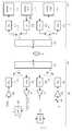
도 6은 본 발명의 제3 실시예에 따른 다종 서비스를 수용하는 광-무선 링크 시스템의 중앙 기지국과 원격 접속 장치의 블록 구성도이다. 도 6을 참조하면, 본 발명의 제3 실시예에 따른 ROF 시스템은 상기 도 3에 도시된 제1 실시예의 구성과 대부분 동일하나, 도 3에 도시된 제1 실시예는 RAU측에 하나의 광대역 안테나를 사용하는 구성을 가지나, 도 6에 도시된 본 발명의 제3 실시예에서는 협대역 안테나를 2개 사용하는 구조를 가지는 점에서 차이가 있다.6 is a block diagram of a central base station and a remote access apparatus of an optical-wireless link system for accommodating multiple services according to a third embodiment of the present invention. Referring to FIG. 6, the ROF system according to the third embodiment of the present invention is mostly the same as the configuration of the first embodiment shown in FIG. 3, but the first embodiment shown in FIG. 3 has one broadband on the RAU side. Although there is a configuration using an antenna, the third embodiment of the present invention shown in FIG. 6 differs in that it has a structure using two narrowband antennas.
즉, 도 6의 RAU(33)는 상기 CAP(31)에서 제1광섬유(35)를 통해 전송된 TDD 하향 신호를 제3광수신기(334)로 전송하며, 제3광송신기(335)에서 출력된 TDD 상향 신호를 제1광섬유(35)를 통해 CAP(31)로 전송하는 제3광서큘레이터(337)를 구비하고, 제3광수신기(334)는 제3광서큘레이터(337)에서 제공된 TDD 하향 신호를 광전 변환하여 제1하향증폭기(331)로 출력하며, 제1하향증폭기(331)는 이를 적절히 증폭하여 제2컴바이너(338)를 통해 제1듀플렉서(339)의 1번 포트로 출력되도록 한다. 제1듀플렉서(339)는 이러한 TDD 하향 신호를 안테나(제1안테나)로 송출하며, 안테나(제1안테나)로부터 수신된 TDD 상향 신호를 상기 제2컴바이너(338)로 출력하여 이를 거쳐 제1상향증폭기(332)로 제공되도록 한다. 제1상향증폭기(332)는 이러한 TDD 상향 신호를 적절히 증폭하여 제3광송신기(335)로 제공하며 제3광송신기(335)는 이를 전광 변환하여 제3광서큘레이터(337)로 출력한다.That is, the
또한, RAU(33)에서는 상기 CAP(31)에서 제2광섬유(36)를 통해 전송된 FDD/방송 하향 신호를 제4광수신기(344)로 전송하며, 제4광송신기(345)에서 출력된 FDD 상향 신호를 제2광섬유(36)를 통해 CAP(31)로 전송하는 제4광서큘레이터(347)를 구비하고, 제4광수신기(344)는 제4광서큘레이터(347)에서 제공된 FDD/방송 하향 신호 를 광전 변환하여 제2하향증폭기(341)로 출력하며, 제2하향증폭기(341)는 이를 적절히 증폭하여 다이플렉서(348)의 2번 포트로 출력한다. 다이플렉서(348)는 제2하향증폭기(341)로부터 제공된 FDD/방송 하향 신호에서 FDD 하향 신호와 방송 신호를 분리하여, 분리된 FDD 하향 신호는 제2듀플렉서(349)의 1번 포트로 출력하며, 방송 신호는 상기 제1듀플렉서(339)의 3번 포트로 출력한다. 제1듀플렉서(339)는 이러한 방송 신호를 안테나(제2안테나)로 송출한다. 제2듀플렉서(349)는 상기 다이플렉서(348)로부터 제공된 FDD 하향 신호를 안테나(제2안테나)로 송출하며, 안테나(제2안테나)로부터 수신된 FDD 상향 신호를 제2상향증폭기(342)로 제공되도록 한다. 제2상향증폭기(342)는 이러한 FDD 상향 신호를 적절히 증폭하여 제4광송신기(345)로 제공하며 제4광송신기(345)는 이를 전광 변환하여 제4광서큘레이터(347)로 출력한다.In addition, the
도 7a, 7b, 7c는 각각 도 6 중 신호여과/분리/합성기로 통칭할 수 있는, 다이플렉서(348) 및 제1, 제2듀플렉서(339, 349)의 동작을 설명하기 위한 S 파라미터 특성 그래프이다. 먼저 도 7a를 참조하면, 다이플렉서(348)는 2번 포트로 입력된 FDD/방송 하향 신호를 FDD 하향 신호와 방송 신호를 분리하여 분리된 FDD 하향 신호를 3번 포트를 통해 출력하며, 방송 신호는 1번 포트를 통해 출력하는데, 이를 위해 도 7a에 도시된 바와 같이, 1, 2번 포트간은 방송 신호 대역(fBroad) 부분을 포함하도록 고대역 필터링하며, 2, 3번 포트간은 FDD 하향 신호 대역(fFDD,down) 부분을 포함하도록 저대역 필터링하며, 양 필터링 대역간은 분리되도록 구성된다. 또한 1, 3번 포트간은 방송 신호 대역(fBroad) 및 FDD 하향 신호 대역(fFDD, down) 이 차단되도록 구성된다.7A, 7B and 7C are S parameter characteristics for explaining the operation of the
도 7b를 참조하면, 제1듀플렉서(339)는 1번 포트로 입력된 TDD 하향 신호를 2번 포트를 통해 안테나로 송출하거나 안테나로부터 2번 포트를 통해 입력된 TDD 상향 신호를 상기 1번 포트로 출력하며, 상기 다이플렉서(348)로부터 3번 포트를 통해 입력된 방송 신호를 상기 2번 포트를 통해 안테나로 출력한다. 이를 위해 도 7b에 도시된 바와 같이, 1, 2번 포트간은 TDD 상향, 하향 신호 대역(fTDD) 부분을 필터링하며, 2, 3번 포트간은 방송 신호 대역(fBroad)을 필터링하도록 구성된다. 또한 1, 3번 포트간은 TDD 상향, 하향 신호 대역(fTDD) 및 방송 신호 대역(fBroad)을 차단하도록 구성된다.Referring to FIG. 7B, the
도 7c를 참조하면, 제2듀플렉서(349)는 1번 포트로 입력된 FDD 하향 신호를 2번 포트를 통해 안테나로 송출하거나 안테나로부터 2번 포트를 통해 입력된 FDD 상향 신호를 상기 3번 포트로 출력하는데, 이를 위해 도 7c에 도시된 바와 같이, 1, 2번 포트간은 FDD 하향 신호 대역(fFDD,down) 부분을 필터링하며, 2, 3번 포트간은 FDD 상향 신호 대역(fFDD,up)을 필터링하도록 구성된다. 또한 1, 3번 포트간은 FDD 신호 대역을 모두 차단하도록 구성된다.Referring to FIG. 7C, the
상기 도 6 및 도 7a~7c에 도시된 바와 같은 구성을 가지는 본 발명의 제3 실시예에 따른 시스템의 RAU(33)측에서의 동작을 살펴보면, CAP(31)로부터 전송된 TDD 하향 신호는 제3광서큘레이터(337)를 거쳐 제3광수신기(334)에 입력되어 광전 변환되고, 이후 제1하향증폭기(331)에서 증폭된 후, 제1듀플렉서(339)를 통해 안테나(제1안테나)로 송출된다. 또한 FDD 하향 신호와 방송 신호는 제4광서큘레이터 (347)를 거쳐 제4광수신기(344)에 입력되어 광전 변환되고, 이후 제2하향증폭기(341)에서 증폭된 후, 다이플렉서(348)에서 FDD 하향 신호와 방송 신호는 분리되어 각각 제2듀플렉서(349)와 제1듀플렉서(339)를 통해 안테나(제1안테나)로 송출된다.Referring to the operation on the
TDD 상향 신호는 안테나(제2안테나)를 통해 수신된 후 제1듀플렉서(339)와, 제1상향증폭기(332)를 거친 후 제3광송신기(335)에서 광신호로 변환되어 제3광서큘레이터(337)를 통해 제1광섬유(35)로 송출된다. 또한 FDD 상향 신호의 경우 안테나(제2안테나)를 통해 수신된 후 제2듀플렉서(349)와 제2상향증폭기(342)를 거친 후 제4광송신기(345)에서 광신호로 변환되어 제4광서큘레이터(347)를 통해 제2광섬유(36)로 송출된다.The TDD uplink signal is received through the antenna (second antenna) and then passed through the
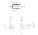
도 8은 본 발명의 제4 실시예에 따른 다종 서비스를 수용하는 광-무선 링크 시스템의 중앙 기지국과 원격 접속 장치의 블록 구성도이다. 도 8을 참조하면, 본 발명의 제4 실시예에 따른 시스템은 도 6에 도시된 제3 실시예의 구성과 대부분 동일하나, 도 5에 도시된 본 발명의 제2 실시예에서의 구성과 유사하게, CAP(51)와 RAU(53)간에 하나의 광섬유를 통해 모든 신호 전송을 수행하기 위한 구조를 가진다.8 is a block diagram of a central base station and a remote access device of an optical-wireless link system for accommodating multiple services according to a fourth embodiment of the present invention. Referring to FIG. 8, the system according to the fourth embodiment of the present invention is mostly the same as that of the third embodiment shown in FIG. 6, but similarly to the configuration of the second embodiment of the present invention shown in FIG. 5. In addition, the
즉, 도 8의 CAP(51)에는 제1, 제2광서큘레이터(317, 327)의 입출력 광신호를 다중화/역다중화하는 제1CWDM(510)이 구비되며, 도 8의 RAU(53)에는 제3, 제4광서큘레이터(337, 347)의 입출력 광신호를 다중화/역다중화하는 제2CWDM((530)이 구비된다. 제1, 제2CWDM(510, 530)간에는 상호간의 광신호를 전송하기 위한 하나의 광섬유, 즉 제3광섬유(55)가 설치된다.That is, the
이러한 구성을 통해, CAP(51)의 TDD 하향 신호와 FDD/방송 하향 신호는 제1CWDM(510)에서 파장다중화되어 RAU(53)의 제2CWDM(530)으로 전송되고, 제2CWDM(530)는 이를 역다중화한다. 또한 RAU953)의 제3, 제4광서큘레이터(337, 347)에서 출력된 TDD, FDD 상향 신호는 제2CWDM(530)에서 파장다중화되어 제1CWDM(510)으로 전송되며, 제1CWDM(510)은 이를 역다중화한다.Through this configuration, the TDD downlink signal and the FDD / broadcast downlink signal of the
상기와 같이 본 발명의 다양한 실시예에 다른 다종 서비스를 수용하는 ROF 링크 시스템의 구성 및 동작이 이루어질 수 있으며, 한편 상기한 본 발명의 설명에서는 구체적인 실시예에 관해 설명하였으나 여러 가지 변형이 본 발명의 범위를 벗어나지 않고 실시될 수 있다. 따라서 본 발명의 범위는 설명된 실시예에 의하여 정할 것이 아니고 청구범위와 청구범위의 균등한 것에 의하여 정하여져야 할 것이다.As described above, the configuration and operation of the ROF link system for accommodating various services in various embodiments of the present invention can be made. It can be carried out without departing from the scope. Therefore, the scope of the present invention should not be defined by the described embodiments, but by the claims and equivalents of the claims.
상기한 바와 같이, 본 발명의 다종 서비스를 수용하는 광-무선 링크 시스템은 상향 링크로 흘러 들어가는 하향 링크 신호를 최소화 해서 전광 변환기나 증폭기가 포화 영역에서 동작하는 것을 막아 상향 링크의 성능을 향상 시킬 수 있다. 또한 방송 신호도 함께 수용함으로써 그 응용범위를 넓히게 되었다. 또한, 본 발명에서는 매우 높은 격리도 특성을 갖는 광서큘레이터를 사용함으로써, 상향 링크와 하향 링크 사이의 분리도를 크게 향상시킬 수 있다. 따라서, 하향 신호의 누설에 의해 능동소자의 비선형 현상이 일어나는 것을 막아 상향 링크 성능의 열화를 막을 수 있다.As described above, the optical-wireless link system accommodating the various services of the present invention can improve downlink performance by minimizing downlink signals flowing into the uplink, preventing all-optical converters or amplifiers from operating in the saturation region. have. In addition, by accommodating broadcast signals, the application range has been expanded. In addition, in the present invention, by using an optical circulator having a very high isolation characteristic, the separation between the uplink and the downlink can be greatly improved. Therefore, it is possible to prevent the nonlinear phenomenon of the active element due to the leakage of the downlink signal to prevent degradation of the uplink performance.
Claims (8)
Translated fromKoreanPriority Applications (2)
| Application Number | Priority Date | Filing Date | Title |
|---|---|---|---|
| KR1020050127761AKR100651544B1 (en) | 2005-12-22 | 2005-12-22 | Optical-to-wireless link system to accommodate multiple services |
| US11/633,838US7796891B2 (en) | 2005-12-22 | 2006-12-05 | ROF link system for supporting various services |
Applications Claiming Priority (1)
| Application Number | Priority Date | Filing Date | Title |
|---|---|---|---|
| KR1020050127761AKR100651544B1 (en) | 2005-12-22 | 2005-12-22 | Optical-to-wireless link system to accommodate multiple services |
Publications (1)
| Publication Number | Publication Date |
|---|---|
| KR100651544B1true KR100651544B1 (en) | 2006-11-30 |
Family
ID=37714142
Family Applications (1)
| Application Number | Title | Priority Date | Filing Date |
|---|---|---|---|
| KR1020050127761AExpired - Fee RelatedKR100651544B1 (en) | 2005-12-22 | 2005-12-22 | Optical-to-wireless link system to accommodate multiple services |
Country Status (2)
| Country | Link |
|---|---|
| US (1) | US7796891B2 (en) |
| KR (1) | KR100651544B1 (en) |
Cited By (2)
| Publication number | Priority date | Publication date | Assignee | Title |
|---|---|---|---|---|
| KR100871229B1 (en) | 2007-03-06 | 2008-12-01 | 삼성전자주식회사 | Wired / wireless integrated network system performing a hybrid duplexing wireless communication service and signal control method therefor |
| KR100930585B1 (en)* | 2007-10-05 | 2009-12-09 | 한국전자통신연구원 | Multiband Signal Separation Conversion Method and Apparatus |
Families Citing this family (12)
| Publication number | Priority date | Publication date | Assignee | Title |
|---|---|---|---|---|
| KR100663466B1 (en)* | 2005-12-09 | 2007-01-02 | 삼성전자주식회사 | Remote Access Unit and Optical Wireless Network Using the Same |
| JP5243615B2 (en)* | 2008-11-05 | 2013-07-24 | テレフオンアクチーボラゲット エル エム エリクソン(パブル) | Dual mode base station |
| TWI385958B (en)* | 2009-03-20 | 2013-02-11 | Ind Tech Res Inst | System for providing wireless communication over a passive optical network (pon) |
| CN102215606B (en)* | 2010-04-02 | 2016-05-25 | 中兴通讯股份有限公司 | Jockey between Base Band Unit and radio frequency unit and method |
| CA2811713A1 (en)* | 2010-09-20 | 2012-03-29 | Aurora Networks, Inc. | Novel rfog cpe device offering enhanced services overlay |
| US8755693B2 (en)* | 2011-05-16 | 2014-06-17 | Eastern Optx, Inc. | Bi-directional, compact, multi-path and free space channel replicator |
| CA2836133A1 (en) | 2011-05-17 | 2012-11-22 | 3M Innovative Properties Company | Converged in-building network |
| TWI511473B (en) | 2013-07-01 | 2015-12-01 | Ind Tech Res Inst | Electronic device and data control method |
| US10003133B2 (en)* | 2016-01-22 | 2018-06-19 | Telekom Malaysia Berhad | Reusable carrier based polarization diversity for uplink of full-duplex radio-over-fiber system |
| KR102539759B1 (en)* | 2016-11-29 | 2023-06-05 | 한국전자통신연구원 | Transmitting apparatus and receiving apparatus using for a mobile front hole |
| CN110661573B (en) | 2019-09-27 | 2020-12-08 | 京信通信系统(中国)有限公司 | ROF communication remote terminal and ROF system |
| JPWO2024134877A1 (en)* | 2022-12-23 | 2024-06-27 |
Citations (4)
| Publication number | Priority date | Publication date | Assignee | Title |
|---|---|---|---|---|
| JP2000091993A (en) | 1998-07-17 | 2000-03-31 | Kokusai Electric Co Ltd | Analog optical transmission system |
| JP2003188826A (en) | 2001-12-14 | 2003-07-04 | Kddi Corp | Optical communication system and method, and optical transceiver |
| KR20030065632A (en)* | 2002-01-30 | 2003-08-09 | 한국과학기술원 | Method and apparatus to decrease and compensate the transmission loss at the wavelength-division multiplexed passive optical network |
| JP2005094630A (en) | 2003-09-19 | 2005-04-07 | Hitachi Kokusai Electric Inc | Analog optical transmission system |
Family Cites Families (1)
| Publication number | Priority date | Publication date | Assignee | Title |
|---|---|---|---|---|
| FI20001686L (en)* | 2000-07-19 | 2002-01-20 | Nokia Mobile Phones Ltd | Multimode transceiver and wireless communication device |
- 2005
- 2005-12-22KRKR1020050127761Apatent/KR100651544B1/ennot_activeExpired - Fee Related
- 2006
- 2006-12-05USUS11/633,838patent/US7796891B2/ennot_activeExpired - Fee Related
Patent Citations (4)
| Publication number | Priority date | Publication date | Assignee | Title |
|---|---|---|---|---|
| JP2000091993A (en) | 1998-07-17 | 2000-03-31 | Kokusai Electric Co Ltd | Analog optical transmission system |
| JP2003188826A (en) | 2001-12-14 | 2003-07-04 | Kddi Corp | Optical communication system and method, and optical transceiver |
| KR20030065632A (en)* | 2002-01-30 | 2003-08-09 | 한국과학기술원 | Method and apparatus to decrease and compensate the transmission loss at the wavelength-division multiplexed passive optical network |
| JP2005094630A (en) | 2003-09-19 | 2005-04-07 | Hitachi Kokusai Electric Inc | Analog optical transmission system |
Cited By (3)
| Publication number | Priority date | Publication date | Assignee | Title |
|---|---|---|---|---|
| KR100871229B1 (en) | 2007-03-06 | 2008-12-01 | 삼성전자주식회사 | Wired / wireless integrated network system performing a hybrid duplexing wireless communication service and signal control method therefor |
| KR100930585B1 (en)* | 2007-10-05 | 2009-12-09 | 한국전자통신연구원 | Multiband Signal Separation Conversion Method and Apparatus |
| US8335200B2 (en) | 2007-10-05 | 2012-12-18 | Electronics And Telecommunications Research Institute | Device and method for separation/conversion of multiband signal |
Also Published As
| Publication number | Publication date |
|---|---|
| US20070147273A1 (en) | 2007-06-28 |
| US7796891B2 (en) | 2010-09-14 |
Similar Documents
| Publication | Publication Date | Title |
|---|---|---|
| US7796891B2 (en) | ROF link system for supporting various services | |
| KR100871229B1 (en) | Wired / wireless integrated network system performing a hybrid duplexing wireless communication service and signal control method therefor | |
| US8059963B2 (en) | Time division duplexing remote station having low-noise amplifier shared for uplink and downlink operations and wired relay method using the same | |
| US7450853B2 (en) | Signal transmission apparatus and method for optical base station | |
| US9356697B2 (en) | Distributed antenna system and method | |
| KR20020063644A (en) | Intermediate-frequency Distributed Antenna System | |
| KR101454091B1 (en) | Method and device for sharing antenna element and antenna assembly | |
| KR20050078044A (en) | Ftth system based on passive optical network for broadcasting service | |
| WO2015024453A1 (en) | Ftth network based optical fiber, and wireless hybrid access system and hybrid access method | |
| EP3759823B1 (en) | Front-end architecture of multiband radio | |
| KR100926373B1 (en) | Multiband Signal Processing System and Signal Processing Method | |
| KR20090058948A (en) | Optical Diplexer Module Using Mixed Signal Multiplexing and Its Method | |
| KR101911356B1 (en) | Rf relay apparatus using time division duplex and frequnecy division duplex | |
| KR20080107795A (en) | Time Division Redundant Optical Wireless Relay System for Automatically Controlling the Gain of RS Receiver and Signal Control Method Using The Same | |
| JP2002141848A (en) | Wireless relay device | |
| KR100473992B1 (en) | TDD Repeater To Obtain Simple Structure and Low Cost Using By Power Switch Module | |
| KR101182035B1 (en) | Remote access unit with multi antena and optical wireless network for bidirectional communication | |
| KR100736118B1 (en) | Integrated relay system for WiBro service | |
| KR101911355B1 (en) | Rf relay apparatus using time division duplex and frequnecy division duplex | |
| KR101015898B1 (en) | Optical diplexer module using mixed-signal multiplexer and method using the same | |
| KR100895169B1 (en) | Time division duplexing remote unit | |
| US20240214103A1 (en) | Optical communication device that transmits wdm signal and transmission control method | |
| KR100681905B1 (en) | Reverse Integrated Optical Repeater | |
| KR100689439B1 (en) | Optical network for two-way wireless communication with remote base station unit | |
| KR100695084B1 (en) | Forward Integrated Optical Repeater |
Legal Events
| Date | Code | Title | Description |
|---|---|---|---|
| A201 | Request for examination | ||
| PA0109 | Patent application | St.27 status event code:A-0-1-A10-A12-nap-PA0109 | |
| PA0201 | Request for examination | St.27 status event code:A-1-2-D10-D11-exm-PA0201 | |
| D13-X000 | Search requested | St.27 status event code:A-1-2-D10-D13-srh-X000 | |
| D14-X000 | Search report completed | St.27 status event code:A-1-2-D10-D14-srh-X000 | |
| E701 | Decision to grant or registration of patent right | ||
| PE0701 | Decision of registration | St.27 status event code:A-1-2-D10-D22-exm-PE0701 | |
| GRNT | Written decision to grant | ||
| PR0701 | Registration of establishment | St.27 status event code:A-2-4-F10-F11-exm-PR0701 | |
| PR1002 | Payment of registration fee | St.27 status event code:A-2-2-U10-U11-oth-PR1002 Fee payment year number:1 | |
| PG1601 | Publication of registration | St.27 status event code:A-4-4-Q10-Q13-nap-PG1601 | |
| PR1001 | Payment of annual fee | St.27 status event code:A-4-4-U10-U11-oth-PR1001 Fee payment year number:4 | |
| PR1001 | Payment of annual fee | St.27 status event code:A-4-4-U10-U11-oth-PR1001 Fee payment year number:5 | |
| PR1001 | Payment of annual fee | St.27 status event code:A-4-4-U10-U11-oth-PR1001 Fee payment year number:6 | |
| R18-X000 | Changes to party contact information recorded | St.27 status event code:A-5-5-R10-R18-oth-X000 | |
| FPAY | Annual fee payment | Payment date:20121030 Year of fee payment:7 | |
| PR1001 | Payment of annual fee | St.27 status event code:A-4-4-U10-U11-oth-PR1001 Fee payment year number:7 | |
| P22-X000 | Classification modified | St.27 status event code:A-4-4-P10-P22-nap-X000 | |
| FPAY | Annual fee payment | Payment date:20131030 Year of fee payment:8 | |
| PR1001 | Payment of annual fee | St.27 status event code:A-4-4-U10-U11-oth-PR1001 Fee payment year number:8 | |
| FPAY | Annual fee payment | Payment date:20141030 Year of fee payment:9 | |
| PR1001 | Payment of annual fee | St.27 status event code:A-4-4-U10-U11-oth-PR1001 Fee payment year number:9 | |
| FPAY | Annual fee payment | Payment date:20151029 Year of fee payment:10 | |
| PR1001 | Payment of annual fee | St.27 status event code:A-4-4-U10-U11-oth-PR1001 Fee payment year number:10 | |
| LAPS | Lapse due to unpaid annual fee | ||
| PC1903 | Unpaid annual fee | St.27 status event code:A-4-4-U10-U13-oth-PC1903 Not in force date:20161123 Payment event data comment text:Termination Category : DEFAULT_OF_REGISTRATION_FEE | |
| PC1903 | Unpaid annual fee | St.27 status event code:N-4-6-H10-H13-oth-PC1903 Ip right cessation event data comment text:Termination Category : DEFAULT_OF_REGISTRATION_FEE Not in force date:20161123 |