KR100651291B1 - Vacuum cleaner - Google Patents
Vacuum cleanerDownload PDFInfo
- Publication number
- KR100651291B1 KR100651291B1KR1020050041154AKR20050041154AKR100651291B1KR 100651291 B1KR100651291 B1KR 100651291B1KR 1020050041154 AKR1020050041154 AKR 1020050041154AKR 20050041154 AKR20050041154 AKR 20050041154AKR 100651291 B1KR100651291 B1KR 100651291B1
- Authority
- KR
- South Korea
- Prior art keywords
- cyclone
- dust collecting
- air
- cylinder
- vacuum cleaner
- Prior art date
- Legal status (The legal status is an assumption and is not a legal conclusion. Google has not performed a legal analysis and makes no representation as to the accuracy of the status listed.)
- Expired - Fee Related
Links
Images


Classifications
- A—HUMAN NECESSITIES
- A47—FURNITURE; DOMESTIC ARTICLES OR APPLIANCES; COFFEE MILLS; SPICE MILLS; SUCTION CLEANERS IN GENERAL
- A47L—DOMESTIC WASHING OR CLEANING; SUCTION CLEANERS IN GENERAL
- A47L9/00—Details or accessories of suction cleaners, e.g. mechanical means for controlling the suction or for effecting pulsating action; Storing devices specially adapted to suction cleaners or parts thereof; Carrying-vehicles specially adapted for suction cleaners
- A47L9/10—Filters; Dust separators; Dust removal; Automatic exchange of filters
- A47L9/16—Arrangement or disposition of cyclones or other devices with centrifugal action
- A47L9/1616—Multiple arrangement thereof
- A47L9/1625—Multiple arrangement thereof for series flow
- A47L9/1633—Concentric cyclones
- A—HUMAN NECESSITIES
- A47—FURNITURE; DOMESTIC ARTICLES OR APPLIANCES; COFFEE MILLS; SPICE MILLS; SUCTION CLEANERS IN GENERAL
- A47L—DOMESTIC WASHING OR CLEANING; SUCTION CLEANERS IN GENERAL
- A47L9/00—Details or accessories of suction cleaners, e.g. mechanical means for controlling the suction or for effecting pulsating action; Storing devices specially adapted to suction cleaners or parts thereof; Carrying-vehicles specially adapted for suction cleaners
- A47L9/10—Filters; Dust separators; Dust removal; Automatic exchange of filters
- A47L9/12—Dry filters
- A47L9/127—Dry filters tube- or sleeve-shaped
- A—HUMAN NECESSITIES
- A47—FURNITURE; DOMESTIC ARTICLES OR APPLIANCES; COFFEE MILLS; SPICE MILLS; SUCTION CLEANERS IN GENERAL
- A47L—DOMESTIC WASHING OR CLEANING; SUCTION CLEANERS IN GENERAL
- A47L9/00—Details or accessories of suction cleaners, e.g. mechanical means for controlling the suction or for effecting pulsating action; Storing devices specially adapted to suction cleaners or parts thereof; Carrying-vehicles specially adapted for suction cleaners
- A47L9/10—Filters; Dust separators; Dust removal; Automatic exchange of filters
- A47L9/16—Arrangement or disposition of cyclones or other devices with centrifugal action
- A47L9/1608—Cyclonic chamber constructions
- A—HUMAN NECESSITIES
- A47—FURNITURE; DOMESTIC ARTICLES OR APPLIANCES; COFFEE MILLS; SPICE MILLS; SUCTION CLEANERS IN GENERAL
- A47L—DOMESTIC WASHING OR CLEANING; SUCTION CLEANERS IN GENERAL
- A47L9/00—Details or accessories of suction cleaners, e.g. mechanical means for controlling the suction or for effecting pulsating action; Storing devices specially adapted to suction cleaners or parts thereof; Carrying-vehicles specially adapted for suction cleaners
- A47L9/10—Filters; Dust separators; Dust removal; Automatic exchange of filters
- A47L9/16—Arrangement or disposition of cyclones or other devices with centrifugal action
- A47L9/1616—Multiple arrangement thereof
- A47L9/1641—Multiple arrangement thereof for parallel flow
- A—HUMAN NECESSITIES
- A47—FURNITURE; DOMESTIC ARTICLES OR APPLIANCES; COFFEE MILLS; SPICE MILLS; SUCTION CLEANERS IN GENERAL
- A47L—DOMESTIC WASHING OR CLEANING; SUCTION CLEANERS IN GENERAL
- A47L9/00—Details or accessories of suction cleaners, e.g. mechanical means for controlling the suction or for effecting pulsating action; Storing devices specially adapted to suction cleaners or parts thereof; Carrying-vehicles specially adapted for suction cleaners
- A47L9/10—Filters; Dust separators; Dust removal; Automatic exchange of filters
- A47L9/16—Arrangement or disposition of cyclones or other devices with centrifugal action
- A47L9/165—Construction of inlets
- A—HUMAN NECESSITIES
- A47—FURNITURE; DOMESTIC ARTICLES OR APPLIANCES; COFFEE MILLS; SPICE MILLS; SUCTION CLEANERS IN GENERAL
- A47L—DOMESTIC WASHING OR CLEANING; SUCTION CLEANERS IN GENERAL
- A47L9/00—Details or accessories of suction cleaners, e.g. mechanical means for controlling the suction or for effecting pulsating action; Storing devices specially adapted to suction cleaners or parts thereof; Carrying-vehicles specially adapted for suction cleaners
- A47L9/10—Filters; Dust separators; Dust removal; Automatic exchange of filters
- A47L9/16—Arrangement or disposition of cyclones or other devices with centrifugal action
- A47L9/1683—Dust collecting chambers; Dust collecting receptacles
Landscapes
- Engineering & Computer Science (AREA)
- Mechanical Engineering (AREA)
- Filters For Electric Vacuum Cleaners (AREA)
Abstract
Translated fromKoreanDescription
Translated fromKorean도 1은 일반적인 진공청소기의 외관 구성을 보인 사시도.1 is a perspective view showing an appearance configuration of a general vacuum cleaner.
도 2는 일반적인 진공청소기 집진유니트의 구성을 보인 사시도.Figure 2 is a perspective view showing the configuration of a general vacuum cleaner dust collection unit.
도 3은 본 발명에 의한 집진유니트의 바람직한 실시예가 진공청소기에서 분리된 상태를 보인 사시도.Figure 3 is a perspective view showing a preferred embodiment of the dust collecting unit according to the present invention separated from the vacuum cleaner.
도 4는 본 발명에 의한 진공청소기 집진유니트의 바람직한 실시예의 분해사시도.Figure 4 is an exploded perspective view of a preferred embodiment of the vacuum cleaner dust collection unit according to the present invention.
도 5는 본 발명 실시예의 종단면도.5 is a longitudinal sectional view of an embodiment of the present invention.
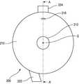
도 6은 본 발명 실시예의 평면도.6 is a plan view of an embodiment of the present invention.
* 도면의 주요 부분에 대한 부호의 설명 *Explanation of symbols on the main parts of the drawings
100. 본체110. 흡입노즐100.
120. 연장관122. 조작부120.
130. 흡입호스140. 착탈노브130.
150. 바퀴160. 토출부150.
180. 집진장착부200. 집진유니트180.
210. 상면커버212. 배기공210.
214. 배기유로216. 안내공214. Exhaust Channel 216. Guideman
218. 노브홈220. 사이클론통218.
222. 흡입유입구224. 집진핸들222.
230. 이물집진통232. 분리벽230. Foreign
234. 1차집진부236. 2차집진부234.
240. 제1사이클론장치242. 가이드통240.
244. 필터250. 제2사이클론장치244.
252. 소사이클론254. 안내관252. Small Cyclone
256. 차단판256. Blocker
본 발명은 진공청소기에 관한 것으로, 보다 상세하게는 공기중의 이물이 이중으로 필터링되도록 구성되는 진공청소기의 집진유니트에 관한 것이다.The present invention relates to a vacuum cleaner, and more particularly, to a dust collecting unit of a vacuum cleaner configured to double-filter foreign matter in the air.
도 1에는 일반적인 진공청소기의 구성이 도시되어 있다. 도시한 바와 같이, 진공청소기는, 실내의 공기를 흡입하는 흡입수단이 내장된 본체(1)와, 상기 본체(1)에서 발생하는 흡입력에 의하여 바닥면의 공기가 유입되는 흡입노즐(2)을 포함하는 구성을 가진다. 1 shows a configuration of a general vacuum cleaner. As shown in the drawing, the vacuum cleaner includes a
한편 상기 본체(1)는, 흡입수단이 수납되어 체결되는 하부몸체(5)와, 상기 하부몸체(5)에 내장된 부품이 외부로 드러나지 않도록 하고, 진공청소기를 제어하는 전장부(미도시)가 내장되는 상부몸체(6)로 구성되어 진다.On the other hand, the
또한 상기 본체(1)가 바닥면을 원활하게 이동할 수 있도록 그 몸체의 양측면에 바퀴(8)가 체결되고, 상기 바퀴(8)에는 흡입노즐(2)을 통하여 흡입된 공기에서 이물질이 분리된 상태의 공기가 본체(1)에서 토출되는 토출부(8a)가 구성되어 진다.In addition,
그리고 상기 본체(1)와 흡입노즐(2) 사이에는, 플렉시블한 재질의 것으로 만들어지는 흡입호스(3b)와, 상기 흡입호스(3b)의 단부에 연결되는 조작부(4)와, 상기 조작부(4)와 흡입노즐(2)을 연결하는 연장관(3a) 등이 순차적으로 설치되어 있어서, 본체(1)에서 발생하는 흡입력을 상기 흡입노즐(2)로 전달할 수 있게 된다.Between the
따라서 상기 본체(1)에 내장되어 있는 전장부(미도시)와 연결된 파워코드(9)를 통하여 전기를 인가하면, 진공청소기는 운전대기 상태가 된다. 이때, 사용자가 조작부(4)의 버튼을 이용하여 흡입단계를 조정하면, 각 단계에 적당한 흡입력이 본체(1)에 내장되어 있는 흡입수단에 의하여 발생된다. Therefore, when electricity is applied through the power cord 9 connected to the electric part (not shown) built in the
상기 흡입수단을 통하여 발생된 흡입력은 흡입연결부(3c)에 체결되어 있는 흡입호스(3b) 및 연장관(3a)을 거쳐 흡입노즐(2)로 전달된다. 상기 흡입노즐(2)로 전달된 흡입력에 의하여 먼지나 보푸라기 등의 이물질이 포함된 공기가 흡입되고, 흡입된 공기중의 이물은 집진유니트(10)에 의하여 분리되며, 이물이 필터링된 공기는 토출부(8a)를 통하여 본체(1) 외부로 토출되는 과정에 의해 청소가 수행된다.The suction force generated through the suction means is transmitted to the
도 2는 종래의 먼지필터(14)가 체결된 상태의 집진유니트(10)를 도시한 것으로, 일측에는 흡입연결부(3c)를 통하여 본체(1)로 유입된 공기가 집진유니트(10) 내벽을 따라 접선방향으로 유동하도록 함으로써 사이클론을 유발하는 흡입유입구 (12)가 성형되고, 내부에는 상기 흡입유입구(12)를 통하여 유입된 질량이 큰 먼지가 분리될 수 있도록 구멍(13a)이 성형된 분리판(13)이 조립되고, 상기 흡입유입구(12)의 타측 외벽에는 본체(1)로부터의 착탈을 용이하도록 하는 손잡이(15)가 구비된다.2 shows a
그리고, 집진유니트(10)의 상부를 개폐 가능하도록 구성되는 상면커버(11)에는, 중앙에 토출구(11a)가 성형되고, 상기 토출구(11a)의 저면 가장자리에 먼지필터(14)가 체결된다.The
상기 먼지필터(14)의 필터몸체(14b)는 길이방향의 주름이 원주방향으로 반복되게 형성된 원통형상을 가지고 있다. 그리고, 상기 필터몸체(14b)의 저부를 고정하여 지지하는 하측고정부(14a) 테두리는 필터몸체(14b)의 저부를 감싸도록 상방으로 일정부분 돌출되어 있다.The
상기 먼지필터(14)의 필터몸체(14b)는, 공기가 강하게 유동되는 것을 고려하여 일정 이상의 강도가 확보되고 세척시 형태를 유지할 수 있는 재질의 것으로 성형하는 것이 바람직하다. 예를 들면, 섬유재로 활용이 가능한 폴리에스테르 재질로 구성할 수도 있다.It is preferable that the
또한 상기 필터몸체(14b)의 상부와 저부를 고정하여 지지하는 상측고정부(미도시)와 하측고정부(14a)도 필터몸체(14b)가 원기둥 형태를 유지할 수 있도록 구성됨과 동시에, 세척이 가능한 합성수지재로 구성할 수도 있다.In addition, the upper and lower fixing portions (not shown) and the
상기 필터몸체(14b)가 길이방향의 주름이 다수개 성형되는 것에 의하여 유동하는 공기와의 접촉표면적을 넓혀줄 수 있게 되므로, 집진효율이 극대화 된다. 즉, 토출구(11a)를 통하여 배출되는 공기에 미세한 이물질이 포함되지 않도록 상기 필터몸체(14b)에 의하여 걸러주게 되는 것이다.Since the
이러한 과정을 거치면서 먼지필터(14)의 필터몸체(14b) 표면에 미세한 이물질이 쌓이게 되면, 공기의 유동이 원활하게 이루어지지 않게 된다. 따라서, 상기 먼지필터(14)의 표면에 묻어있는 이물질을 털어주거나 세척해야 한다.If fine foreign matter is accumulated on the surface of the
그러나 상기와 같이 구성되는 종래의 진공청소기에서는 공기중의 이물이 상기 먼지필터(14)에 의해 단한번 필터링되므로, 공기의 정화능력이 낮은 문제점이 있다. However, in the conventional vacuum cleaner configured as described above, since foreign matters in the air are filtered only once by the
상기와 같은 종래의 문제점을 해결하기 위한 본 발명의 목적은, 공기중의 이물이 이중으로 필터링되는 진공청소기의 집진유니트를 제공하는 것이다.An object of the present invention for solving the conventional problems as described above is to provide a dust collecting unit of the vacuum cleaner in which foreign matter in the air is filtered twice.
본 발명의 다른 목적은, 집진핸들과 흡입구가 집진통의 외면에 서로 대칭되는 위치에 형성되지 않는 진공청소기의 집진유니트를 제공하는 것이다.Another object of the present invention is to provide a dust collecting unit of a vacuum cleaner in which the dust collecting handle and the suction port are not formed at positions symmetrical with each other on the outer surface of the dust collecting container.
상기와 같은 목적을 달성하기 위한 본 발명의 특징에 따르면, 다수의 사이클론장치가 내부에 구비되는 사이클론통과; 상기 사이클론통에 형성되어, 사이클론통 외측으로부터 내측으로 공기를 안내하는 흡입유입구와; 상기 사이클론통의 외면에 형성되어, 사용자의 취부를 용이하게 하는 집진핸들과; 상기 사이클론통 내부에 구비되어, 공기중의 이물을 1차적으로 분리하는 제1사이클론장치와; 상기 제1사이클론장치의 일측에 구비되어, 공기중의 이물을 2차적으로 분리하는 제2사이클론장치 와; 상기 사이클론통의 하측에 일체로 또는 별개로 구비되며, 필터링된 이물이 집진되는 이물집진통과; 상기 사이클론통의 상측에 구비되어, 사이클론통의 상부를 개폐하는 상면커버;를 포함하는 구성을 가지며; 상기 흡입유입구는, 상기 집진핸들이 형성되는 상기 사이클론통의 반대편 대칭위치로부터 일측으로 치우쳐 형성됨을 특징으로 한다.According to a feature of the present invention for achieving the above object, a plurality of cyclone passages provided therein; A suction inlet formed in the cyclone cylinder and guiding air from the outside to the inside of the cyclone cylinder; A dust collecting handle formed on an outer surface of the cyclone barrel to facilitate mounting of a user; A first cyclone device provided inside the cyclone cylinder and separating the foreign matter in the air primarily; A second cyclone device provided at one side of the first cyclone device to separate foreign matter in the air secondaryly; A foreign matter collecting passage provided integrally or separately at a lower side of the cyclone barrel, in which filtered foreign matter is collected; It is provided on the upper side of the cyclone cylinder, the top cover for opening and closing the upper portion of the cyclone cylinder; The suction inlet is characterized in that it is formed biased to one side from the opposite symmetrical position of the cyclone cylinder in which the dust collecting handle is formed.
이와 같이 구성되는 본 발명에 의하면 진공청소기의 이물 필터링 능력이 향상되고, 사용편의성이 증대되는 이점이 있다.According to the present invention configured as described above, there is an advantage that the foreign material filtering capability of the vacuum cleaner is improved, and the ease of use is increased.
이하에서는 캐니스터형 진공청소기에 채용되는 집진유니트를 예로 들어 살펴보기로 한다.Hereinafter, the dust collecting unit employed in the canister vacuum cleaner will be described as an example.
도 3은 본 발명에 의한 진공청소기 집진유니트의 바람직한 실시예가 진공청소기 본체로부터 분리된 상태가 도시되어 있다.Figure 3 shows a preferred embodiment of the vacuum cleaner dust collection unit according to the present invention is separated from the vacuum cleaner body.
도면에 도시한 바와 같이, 진공청소기는 전원 인가시에 회전하는 모터(미도시)가 내장되어 흡입력을 발생하는 본체(100)와, 바닥면에 근접한 상태로 이동하여 상기 본체(100)로부터 발생된 흡입력으로 이물을 흡입하는 흡입노즐(110) 등으로 구성된다.As shown in the figure, the vacuum cleaner is built in a motor (not shown) that rotates when the power is applied and generates a suction force, and moves in a state close to the bottom surface generated from the
상기 본체(100)에는 전방에서 선택적으로 분리 가능하게 장착되어, 상기 본체(100) 내부로 유입된 이물을 사이클론 방식으로 필터링하여 집진하는 집진유니트(200)가 구비된다.The
그리고, 상기 흡입노즐(110)과 본체(100) 사이에는 길이 조정이 가능한 연장관(120)과 흡입호스(130)가 더 구비되어, 상기 흡입노즐(110)을 통해 유입되는 공 기와 이물을 상기 본체(100)로 안내한다.In addition, between the
보다 상세하게는 상기 연장관(120)은 상기 흡입노즐(110)과 연결 설치되며, 상기 연장관(120)과 상기 본체(100) 사이에 흡입호스(130)가 연결 설치된다. 그리고, 상기 흡입호스(130)는 플렉시블한 재질로 구비되어 상기 흡입노즐(110)의 유동이 보다 용이하도록 지지한다.In more detail, the
상기 연장관(120)의 일단부에는 진공청소기의 작동을 사용자가 조작할 수 있도록 하는 조작부(122)가 설치된다.One end of the
상기 본체(100)의 상면 선단부에는 상기 집진유니트(200) 일측을 구속함으로써 집진유니트(200)의 이탈을 규제하는 착탈노브(140)가 구비된다.An upper end portion of the
보다 상세하게는, 상기 본체(100)의 착탈노브(140) 일단이 아래에서 설명할 집진유니트(200)의 노브홈(218)에 걸려 고정되면, 상기 집진유니트(200)는 본체(100)에 고정된다.More specifically, when one end of the
상기 본체(100)의 후방 양측에는 넓은 청소영역 유동시에 용이하도록 한쌍의 바퀴(150)가 장착되며, 상기 바퀴(150) 내부에는 상기 집진유니트(200)에 의해서 정화된 공기가 본체(100) 외부 즉, 실내로 토출되도록 하는 토출부(160)가 형성된다. 그리고, 상기 본체(100) 상면에는 사용자가 상기 본체(100)를 이동시에 파지 가능하도록 중앙부가 본체(100) 상면과 이격된 손잡이(170)가 구비된다.A pair of
상기 본체(100)의 전방에는 상기 집진유니트(200)가 안착되는 집진장착부(180)가 형성된다. 상기 집진장착부(180)는 후방이 개구되도록 형성되며, 상기 집진유니트(200)의 외형과 대응되는 크기의 공간을 가진다.In front of the
상기 집진장착부(180)의 저면에는 지지돌기(182)가 더 형성된다. 상기 지지돌기(182)는 상기 집진장착부(180)의 저면으로부터 상방으로 돌출 형성되어, 아래에서 설명할 집진유니트(200)의 지지홈(238)에 삽입된다.A
상기 집진장착부(180)에는 집진유니트(200)가 장착된다. 상기 집진유니트(200)는 공기중의 이물을 걸러내어 집진하기 위한 것으로, 필터(filter)를 사용하여 공기중의 이물을 제거하거나 원심력을 이용한 싸이클론 방식에 의해 공기를 정화하게 된다. 물론 필터나 싸이클론을 동시에 사용하는 구성을 가지기도 한다.The
도 4에는 본 발명에 의한 진공청소기 집진유니트의 분해사시도가 도시되어 있으며, 도 5에는 본 발명에 의한 진공청소기 집진유니트의 종단면이 도시되어 있다. 그리고, 도 6에는 본 발명 실시예에 의한 집진유니트가 평면도로 도시되어 있다.Figure 4 shows an exploded perspective view of the vacuum cleaner dust collection unit according to the present invention, Figure 5 shows a longitudinal section of the vacuum cleaner dust collection unit according to the present invention. 6 shows a dust collecting unit according to an embodiment of the present invention in plan view.
이들 도면에 도시된 바와 같이, 상기 집진유니트(200)는, 상면외관을 형성하는 상면커버(210)와; 상하로 관통된 원통형상으로 이루어져, 외관을 형성하는 사이클론통(220)과; 상기 사이클론통(220)을 관통 형성되어, 사이클론통(220) 외측으로부터 내측으로 공기를 안내하는 흡입유입구(222)와; 상기 사이클론통(220)의 외면에 형성되어, 사용자의 취부를 용이하게 하는 집진핸들(224)과; 상기 사이클론통(220) 하측에 구비되는 이물집진통(230)과; 상기 사이클론통(220) 내부에 구비되어, 공기중의 이물을 1차적으로 분리하는 제1사이클론장치(240)와; 상기 제1사이클론장치(240)의 일측에 구비되어, 공기중의 이물을 원심력을 이용하여 2차적으로 분리하는 제2사이클론장치(250) 등으로 이루어진다.As shown in these figures, the
상기 사이클론통(220)에는 흡입유입구(222)가 관통하여 설치된다. 상기 흡입유입구(222)는 원통 또는 사각기둥 형상을 가지는 것이 바람직하다. 상기 흡입유입구(222)는 상기 본체(100) 내부로 유입된 이물을 포함한 공기가 집진유니트(200) 내부로 유입되도록 가이드하는 것으로, 내측단은 아래에서 설명할 가이드통(242)에 연결된다.The
상기 흡입유입구(222)가 형성되는 상기 사이클론통(220)의 반대편에는 집진핸들(224)이 형성된다. 상기 사이클론통(220)의 일측 외주면에는 흡입유입구(222)가 형성되고, 타측 외주면에는 중앙부가 외주면과 이격되도록 형성된 집진핸들(224)이 구비되어 사용자의 파지를 용이하게 한다.A dust collecting handle 224 is formed on the opposite side of the
상기 집진핸들(224)과 상기 흡입유입구(222)는 상기 사이클론통(220)의 외면 반대편에 각각 형성되나, 이러한 집진핸들(224)과 흡입유입구(222)는 서로 대칭되는 위치에 형성되지는 않는다. 즉, 대칭되는 위치의 일측으로 치우치게 형성된다.The dust collecting handle 224 and the
도 6에 도시된 바와 같이, 상기 흡입유입구(222)는 상기 집진핸들(224)와 상기 집진유니트(200)의 중앙(O)을 지나는 단면(A-A')의 좌측으로 치우쳐 형성된다.As shown in FIG. 6, the
보다 상세하게는, 상기 흡입유입구(222)는 상기 집진핸들(224)와 상기 사이클론통(220)의 중앙(O)을 지나는 단면(A-A')의 좌측으로 치우쳐 형성되며, 이러한 상기 흡입유입구(222)는 상기 집진유니트(200)의 외주면으로부터 외측으로 갈수록 점차 우측으로 치우치도록 형성된다.More specifically, the
상기 사이클론통(220)의 하단 내주면에는 암나사부(220')가 형성된다. 상기 암나사부(220')는 아래에서 설명할 이물집진통(230)의 상단에 형성되는 수나사부 (230')와 나사 결합되는 부분이다.A
상기 사이클론통(220) 내부에는 상기한 제1사이클론장치(240)가 구비된다. 상기 제1사이클론장치(240)는 상기 흡입유입구(222)를 통해서 상기 사이클론통(220) 내부로 유입된 이물을 1차적으로 필터링하는 것이다.The
상기 제1사이클론장치(240)는 상기 사이클론통(220) 내부에 구비되어, 상기 흡입유입구(222)를 통해 유입되는 공기가 나선방향으로 선회하도록 가이드하는 원통 형상의 가이드통(242)과, 상기 가이드통(242)의 내부에 설치되어 공기중의 이물을 걸러내는 필터(244) 등으로 구성된다.The
상기 가이드통(242)은 상기 사이클론통(220)과 대응되는 원통 형상으로 이루어지며, 상하의 길이도 상기 사이클론통(220)의 상하 길이와 대응되는 크기를 가지도록 형성됨이 바람직하다.The
한편, 상기 가이드통(242)은 상기 흡입유입구(222)에 의해 상기 사이클론통(220)과 일체로 형성되며, 상기 흡입유입구(222)의 내측단은 상기 가이드통(242)과 소정의 경사를 가지도록 연결된다. 따라서 상기 흡입유입구(222)를 통해 상기 가이드통(242) 내부로 유입되는 공기는 가이드통(242)의 내주면을 따라서 나선방향으로 선회하게 된다.On the other hand, the
상기 필터(244)는 공기중의 이물을 필터링하는 기능을 가지는 한 다양한 구성을 가질 수 있다. 즉, 종래와 같은 절곡필터 등으로 이루어지거나, 공기가 통과 가능한 다수의 통기공이 형성된 플라스틱 재질의 원통으로 이루어지는 질 수도 있다.The
상기 필터(244)는 원통 형상으로 이루어져, 내부에는 에어통과홀(244a)이 형성된다. 상기 에어통과홀(244a)의 하단은 아래에서 설명할 분리판(244")에 의해 차폐되고, 상단은 개구된다.The
상기 필터(244)의 상단에는 아래에서 설명할 제2사이클론장치(250)의 차단판(256) 저면에 체결되는 필터체결부(244')가 형성되고, 하단에는 상기 가이드통(242)의 하단부에 위치되어 가이드통(242)의 내부와 하측으로 구획하는 분리판(244")이 형성된다.The upper end of the
상기 분리판(244")에는 이물이 관통되는 이물관통공(244"a)이 적어도 하나 이상 형성됨이 바람직하며, 아래에서 설명할 1차집진부(234) 내부에 집진된 이물이 공기 유동에 의해서 다시 상방으로 비산(飛散)되지 않도록 한다.At least one foreign body through-
한편, 상기 제1사이클론장치(240)의 상측에는 전술한 제2사이클론장치(250)가 구비된다. 상기 제2사이클론장치(250)는 상기 제1사이클론장치(240)의 사이클론에 의해서 크고 무거운 이물이 필터링된 공기를 2차적으로 필터링하는 것이다.On the other hand, the
상기 제2사이클론장치(250)는, 하반부가 콘(corn) 형상을 가지는 다수개의 소사이클론(252)과, 상기 다수의 소사이클론(252)의 내측에 구비되는 원통 형상의 안내관(254) 등으로 이루어진다.The
상기 소사이클론(252)은 상기 사이클론통(220)의 상면을 차폐하는 차단판(256)에 일체로 형성됨이 바람직하다. 상기 차단판(256)은 상기 사이클론통(220)의 상면과 대응되는 원판으로 이루어지며, 중앙부에는 소정의 연통공(256')이 상하로 관통 형성된다.The
상기 연통공(256')은 상기 필터(244)의 에어통과홀(244a) 크기와 대응되는 크기를 가지도록 형성됨이 바람직하다. 따라서 상기 에어통과홀(244a)에 의해 상방으로 안내되는 공기는 상기 연통공(256')을 통과하여 상측으로 이동하게 되는 것이다.The
상기 소사이클론(252)은 상기 연통공(256')의 외측에 방사상으로 다수개가 형성된다. 보다 상세하게는 도시된 바와 같이, 상기 소사이클론(252)은 상기 차단판(256)을 상하로 관통하도록 형성된다.The
상기 소사이클론(252)은 하단부가 콘(corn) 형상으로 이루어지고, 상단부는 원통 형상으로 이루어진다. 그리고, 이러한 상단부는 일측이 개구되고, 개구된 일단은 외측으로 소정 길이로 연장 형성되어 유입안내편(252')을 형성한다.The
따라서, 상기 유입안내편(252')에 의해 안내되는 공기와 이물을 상기 소사이클론(252) 내부로 나선 방향으로 회전하면서 유입된다.Therefore, the air and the foreign material guided by the inflow guide piece 252 'is introduced while rotating in a spiral direction into the
상기 안내관(254)은 상기 소사이클론(252)의 상단 직경보다는 상대적으로 작은 직경을 가지도록 형성되어, 상기 소사이클론(252)의 내부에 위치된다. 따라서 상기 소사이클론(252)을 따라 선회하던 공기의 중앙에 형성되는 상승기류가 상기 안내관(254)에 의해 안내되어 상측으로 이동한다. 상기 안내관(254)은 아래에서 설명할 상면커버(210)에 일체로 형성됨이 바람직하다.The
상기 제2사이클론장치(250)의 상부에는 상면커버(210)가 구비된다. 즉, 상기 사이클론통(220)의 상측에는 상면커버(210)가 체결되어 사이클론통(220)의 상부를 개폐한다.An
상기 상면커버(210)는 상기 집진유니트(200)의 상면 외관을 형성하는 것으로, 상면에는 원형으로 천공된 배기공(212)이 형성되어 상기 제2사이클론장치(250)에 의해 정화된 공기가 상기 집진유니트(200)의 상방으로 배기되도록 한다.The
상기 상면커버(210) 내부에는 배기유로(214)가 더 형성된다. 즉, 상기 상면커버(210)의 상면으로부터 하측으로 소정 거리 이격된 위치에는 구획판(214')이 형성되고, 이러한 구획판(214')과 상면커버(210)의 상면 사이에는 소정의 공간인 배기유로(214)가 형성된다.An
상기 구획판(214')의 저면에는 상기 안내관(254)이 하측으로 돌출 형성된다. 따라서 상기 상면커버(210)가 상기 사이클론통(220)에 결합되면, 상기 안내관(254)이 상기 소사이클론(252) 내측에 위치되고, 상기 소사이클론(252)은 상기 사이클론통(220)의 내주면과 상기 가이드통(242)의 외주면 사이에 위치하게 된다.The
상기 안내관(254)의 상단부에는 도 5에 도시된 바와 같이, 상기 배기공(212)과 연통되는 안내공(216)이 천공 성형된다. 상기 안내공(216)은 상기 제2사이클론장치(250)에 의해서 정화된 공기가 상기 안내관(254) 내부를 통해서 상방으로 유동하여 통과하는 통로가 된다.As shown in FIG. 5, a
상기 상면커버(210)의 상면에는 상기 착탈노브(140)가 삽입되는 노브홈(218)이 더 형성된다. 따라서 상기 착탈노브(140)가 상기 노브홈(218)에 삽입되면, 상기 집진유니트(200)가 상기 본체(100)에 장착되는 것이다.A
한편, 상기 사이클론통(220)의 하측에는 상부가 개구된 용기 모양으로 형성된 이물집진통(230)이 구비된다. 상기 이물집진통(230)은 집진유니트(200)의 하부 외관을 형성하며, 상기 제1사이클론장치(240) 및 제2사이클론장치(250)에 의해서 필터링되어 낙하된 이물이 집진되는 부분이다.On the other hand, the lower side of the
상기 이물집진통(230) 내부에는 원통모양의 분리벽(232)이 구비된다. 상기 분리벽(232)은 상기 이물집진통(230) 내부공간을 구획하는 것으로 상단부가 상기 가이드통(242)의 하단과 접하도록 구성된다. 따라서, 상기 분리벽(232)의 상단과 상기 가이드통(242)의 하단 사이에는 밀봉부재(도시되지 않음)가 더 구비되기도 한다.The foreign
상기 분리벽(232) 내부에는 상기 제1사이클론장치(240)에 의해서 필터링된 이물이 집진되는 1차집진부(234)가 형성되고, 외측에는 2차집진부(236)가 형성된다. 즉, 상기 분리벽(232) 외주면과 이물집진통(230) 내주면이 이루는 공간에는 상기 제2사이클론장치(250)에 의해서 필터링되어 낙하된 이물이 집진되는 2차집진부(236)가 형성된다.In the
상기 이물집진통(230)의 상단 외주면에는 수나사부(230')가 형성된다. 상기 수나사부(230')는 상기 사이클론통(220)의 하단에 형성되는 암나사부(220')와 대응되는 나사산이 형성되는 부분이다. 따라서 상기 이물집진통(230)의 수나사부(230')와 상기 사이클론통(220)의 암나사부(220')가 서로 나사체결되면, 상기 이물집진통(230)이 상기 사이클론통(220)과 체결된다.A
상기 이물집진통(230)의 바닥면에는 상방으로 함몰된 지지홈(238)이 형성된다. 상기 지지홈(238)은 상기 집진유니트(200)를 집진장착부(180)에 장착시에 장착방향을 가이드하는 것으로, 상기 지지돌기(182)에 의해서 좌우측 방향의 유동이 규 제됨으로써 이러한 역할은 수행 가능하게 된다. 즉, 상기 지지홈(238)에는 상기 지지돌기(182)가 삽입된다.A
이하에서는 상기와 같이 구성되는 진공청소기의 작용을 살펴본다.Hereinafter, look at the action of the vacuum cleaner configured as described above.
상기 조작부(122)의 조작에 의해 진공청소기의 작동이 시작되면, 외부로부터 인가되는 전원에 의해 상기 본체(100)의 내부에 구비된 모터(미도시)가 작동하여 흡인력을 발생시킨다. 따라서 이러한 흡인력에 의해 상기 흡입노즐(110)을 통해 외부의 공기와 이물이 흡입된다.When the operation of the vacuum cleaner is started by the operation of the
상기 흡입노즐(110)을 통해 흡입되는 공기와 이물은 상기 연장관(120)과 흡입호스(130)를 차례로 지나, 상기 본체(100)로 안내된다.Air and foreign matter sucked through the
상기 본체(100)로 안내된 공기와 이물을 상기 집진유니트(200) 내부로 유입되어 정화된다.Air and foreign matter guided to the
보다 상세하게 살펴보면, 상기 집진유니트(200)의 흡입유입구(222)를 통해 유입되는 공기와 이물을 먼저 상기 제1사이클론장치(240)에 의해 1차적으로 필터링된다. 즉, 상기 가이드통(242) 내부로 유입되는 공기와 이물을 나선 방향으로 회전하면서 회전하다가 상대적으로 무게가 큰 이물은 상기 분리판(244")의 이물관통공(244"a)의 통해 하측으로 내려와, 상기 1차집진부(234)에 쌓이게 된다.In more detail, air and foreign matter introduced through the
그리고 상기 가이드통(242)을 선회하는 공기중의 이물은 상기 필터(244)를 통과하면서 다시 필터링되고, 필터(244)를 통과한 공기는 상기 필터(244) 내측의 에어통과홀(244a)을 통해 상방으로 안내되어 상기 차단판(256) 상부로 이동한다.The foreign material in the air turning the
상기 차단판(256) 상부로 이동된 공기와 미세이물은 상기 유입안내편(252') 에 의해 가이드되어 상기 소사이클론(252) 내부로 유입된다. 상기 소사이클론(252) 내부로 유입되는 공기와 미세이물은 소사이클론(252)의 내주면을 따라 나선방향으로 선회하면서 하측으로 점차 이동하게 된다.Air and fine foreign matter moved to the blocking
상기 소사이클론(252)의 하단부는 콘(corn) 형상으로 이루어져 있으므로, 소사이클론(252) 내부의 벽면을 선회하면서 하측으로 이동되는 공기의 이동속도는 점차 증가하게 되고, 이때 소사이클론(252)의 중앙부에는 상승기류가 형성된다.Since the lower end portion of the
따라서, 상기 소사이클론(252)의 내부 벽멱을 따라 선회하던 공기는 상기 안내관(254)을 통해 다시 상승하게 되고, 이 과정에서 상대적으로 공기보다 질량이 큰 미세이물은 원심력과 관성력에 의해 상승기류에 편입되지 못하고 상기 소사이클론(252)의 하측으로 분출된다.Therefore, the air turning along the inner wall 소 of the
상기 소사이클론(252)의 하측으로 분출된 이물은 상기 2차집진부(236)에 쌓이게 된다.Foreign substances ejected to the lower side of the
그리고, 상기 다수의 안내관(254)을 통해 상승하는 공기는 상기 구획판(214')과 상기 상면커버(210) 상면 사이에 형성된 배기유로(214)에서 모아져 상기 배기공(212)을 통해 집진유니트(200)의 외부로 토출된다.In addition, air rising through the plurality of
상기 집진유니트(200)에서 1,2차에 걸쳐 정화된 공기는 상기 본체(100)의 모터(도시되지 않음)를 거쳐 상기 토출부(160)를 통해 본체(100) 외부로 배출된다.The air purified in the
한편, 오랜 기간동안의 청소 수행으로 상기 이물집진통(230) 내부에 많은 이물이 쌓이게 되면 사용자는 상기 집진유니트(200) 내부로부터 이물을 제거해야 할 필요가 있다.On the other hand, if a lot of foreign matter is accumulated in the foreign matter
이때에는 먼저 상기 집진유니트(200)를 상기 본체(100)로부터 분리하여야 하는데, 상기 본체(100)의 착탈노브(140)가 상기 집진유니트(200)의 노브홈(218)으로부터 벗어나도록 한 상태에서 상기 집진핸들(224)를 파지하여 전방으로 당긴다.In this case, first, the
이렇게 되면, 상기 집진유니트(200)가 분리되고, 다음으로는 상기 이물집진통(230)을 반시계방향으로 회전시켜 사이클론통(220)으로부터 분리한다. 즉, 상기 이물집진통(230)과 상기 사이클론통(220)은 나사결합되어 있으므로 회전에 의해 나사결합을 해지한다.In this case, the
상기 이물집진통(230)이 사이클론통(220)으로부터 분리되면, 내부의 1차집진부(234)와 2차집진부(236)에 쌓인 이물을 동시에 제거할 수 있게 된다.When the foreign
상기와 같은 과정에 의해 이물집진통(230) 내부의 이물이 제거되고 나면, 상기의 분리와 역순에 의해 상기 이물집진통(230)을 상기 사이클론통(220)에 체결하고, 상기 집진유니트(200)를 상기 본체(100)에 장착한다.After the foreign matter inside the foreign
이러한 본 발명의 범위는 상기에서 예시한 실시예에 한정되지 않고, 상기와 같은 기술범위 안에서 당업계의 통상의 기술자에게 있어서는 본 발명을 기초로 하는 다른 많은 변형이 가능할 것이다.The scope of the present invention is not limited to the above-exemplified embodiments, and many other modifications based on the present invention will be possible to those skilled in the art within the above technical scope.
예를 들어, 상기의 실시예에서는 도 6에 도시된 바와 같이, 상기 흡입유입구(222)는 상기 집진핸들(224)와 상기 사이클론통(220)의 중앙(O)을 지나는 단면(A-A')의 좌측으로 치우쳐 형성된다. 그러나 이러한 구성외에 상기 흡입유입구(222)가 상기 집진핸들(224)와 상기 사이클론통(220)의 중앙(O)을 지나는 단면(A-A')의 우측으로 치우쳐 형성되도록 구성할 수 있음은 당연하다.For example, in the above embodiment, as shown in FIG. 6, the
또한 이와 같이 상기 흡입유입구(222)가 상기 집진핸들(224)와 상기 사이클론통(220)의 중앙(O)을 지나는 단면(A-A')의 우측으로 치우쳐 형성되는 경우에는 상기 흡입유입구(222) 상기 집진유니트(200)의 외주면으로부터 외측으로 갈수록 점차 좌측으로 치우치도록 형성될 것이다.In addition, when the
그리고, 상기 실시예에서는 상기 이물집진통(230)과 상기 사이클론통(220)은 서로 별개로 이루어져 나사결합되는 구성으로 되어 있으나, 이러한 구성외에 상기 이물집진통(230)과 상기 사이클론통(220)이 일체로 형성되는 구성도 가능하다.In addition, in the above embodiment, the foreign
뿐만 아니라, 상기 실시예에서는 상기 사이클론통(220)이 상하로 관통되는 원통 형상으로 이루어진 경우를 예시하고 있으나, 이러한 사이클론통(220)의 상면이 차폐되면서 여기에 상기 다수의 소사이클론(252)이나 안내관(254)이 일체로 형성되는 등의 구성도 가능함은 물론이다.In addition, in the above embodiment, the
상기와 같은 본 발명에 의한 진공청소기는, 집진유니트의 하부외관을 형성하고 내부에 필터링된 이물이 집진되는 이물집진통이 본체로부터 독립적으로 분리 가능하며, 공기중의 이물이 두번에 걸쳐 필터링된다. 따라서, 진공청소기의 공기 정화능력(이물 필터링 능력)이 향상되는 이점이 있다.In the vacuum cleaner according to the present invention as described above, the foreign body dust collector which forms the lower appearance of the dust collecting unit and the foreign matter filtered therein is separable independently from the main body, and foreign matter in the air is filtered twice. Therefore, there is an advantage that the air purification capacity (foreign matter filtering ability) of the vacuum cleaner is improved.
뿐만 아니라, 본 발명에서는 이물집진통의 분리만으로 제1사이클론장치에 의해 필터링된 이물은 물론 제2사이클론장치에 의해 필터링된 이물도 동시에 분리 가능하므로, 사용편의성이 증대되는 이점이 있다.In addition, in the present invention, since the foreign material filtered by the first cyclone device as well as the foreign material filtered by the second cyclone device can be separated at the same time only by separating the foreign matter collecting cylinder, there is an advantage in that the convenience of use is increased.
그리고, 본 발명에서는 흡입유입구가 집진핸들이 형성되는 사이클론통의 반 대편 대칭위치로부터 일측으로 치우쳐 형성되고, 이러한 흡입유입구는 집진유니트의 외주면으로부터 외측으로 갈수록 점차 다른 일측으로 치우치도록 형성된다. 따라서, 본 발명에 의하면 집진유니트의 체결이 용이하며, 집진유니트 내부로 유입되는 공기가 집진유니트 내면을 따라 자연스럽게 선회하여 사이클론 유동을 형성하게 되는 효과가 있다.In addition, in the present invention, the suction inlet is formed to be biased to one side from the opposite symmetrical position of the cyclone cylinder in which the dust collecting handle is formed. Therefore, according to the present invention, it is easy to fasten the dust collecting unit, and the air flowing into the dust collecting unit naturally turns along the inner surface of the dust collecting unit to form a cyclone flow.
Claims (8)
Translated fromKoreanPriority Applications (1)
| Application Number | Priority Date | Filing Date | Title |
|---|---|---|---|
| KR1020050041154AKR100651291B1 (en) | 2005-05-17 | 2005-05-17 | Vacuum cleaner |
Applications Claiming Priority (1)
| Application Number | Priority Date | Filing Date | Title |
|---|---|---|---|
| KR1020050041154AKR100651291B1 (en) | 2005-05-17 | 2005-05-17 | Vacuum cleaner |
Publications (2)
| Publication Number | Publication Date |
|---|---|
| KR20060118801A KR20060118801A (en) | 2006-11-24 |
| KR100651291B1true KR100651291B1 (en) | 2006-11-29 |
Family
ID=37705754
Family Applications (1)
| Application Number | Title | Priority Date | Filing Date |
|---|---|---|---|
| KR1020050041154AExpired - Fee RelatedKR100651291B1 (en) | 2005-05-17 | 2005-05-17 | Vacuum cleaner |
Country Status (1)
| Country | Link |
|---|---|
| KR (1) | KR100651291B1 (en) |
Cited By (2)
| Publication number | Priority date | Publication date | Assignee | Title |
|---|---|---|---|---|
| CN102551609A (en)* | 2012-02-06 | 2012-07-11 | 胡海荣 | Cyclone separating type dust cup of dust collector |
| KR102015092B1 (en)* | 2018-08-30 | 2019-10-21 | 삼성전자주식회사 | Dust collecting apparatus and cleaner having the same |
Families Citing this family (38)
| Publication number | Priority date | Publication date | Assignee | Title |
|---|---|---|---|---|
| KR100864708B1 (en)* | 2006-12-28 | 2008-10-23 | 삼성광주전자 주식회사 | Multi Cyclone Dust Collector for Vacuum Cleaner |
| CN101939110B (en) | 2007-12-19 | 2015-01-21 | Gbd公司 | Structure of cyclone separator assembly and surface cleaning device having said cyclone separator assembly |
| US10722086B2 (en) | 2017-07-06 | 2020-07-28 | Omachron Intellectual Property Inc. | Handheld surface cleaning apparatus |
| US10674884B2 (en) | 2013-02-28 | 2020-06-09 | Omachron Intellectual Property Inc. | Hand carryable surface cleaning apparatus |
| US9456721B2 (en) | 2013-02-28 | 2016-10-04 | Omachron Intellectual Property Inc. | Surface cleaning apparatus |
| US10729294B2 (en) | 2013-02-28 | 2020-08-04 | Omachron Intellectual Property Inc. | Hand carryable surface cleaning apparatus |
| US10791889B2 (en) | 2016-01-08 | 2020-10-06 | Omachron Intellectual Property Inc. | Hand carryable surface cleaning apparatus |
| US11950745B2 (en) | 2014-12-17 | 2024-04-09 | Omachron Intellectual Property Inc. | Surface cleaning apparatus |
| CN104840152A (en) | 2015-06-09 | 2015-08-19 | 莱克电气股份有限公司 | Handheld dust collector with spiral two-level tornado dust-air separation structure |
| US9962048B2 (en) | 2016-01-08 | 2018-05-08 | Omachron Intellectual Property | Hand carryable surface cleaning apparatus |
| US10165914B2 (en) | 2016-01-08 | 2019-01-01 | Omachron Intellectual Property Inc. | Hand carryable surface cleaning apparatus |
| US9980616B2 (en) | 2016-01-08 | 2018-05-29 | Omachron Intellectual Property Inc. | Hand carryable surface cleaning apparatus |
| US12390062B2 (en) | 2016-01-08 | 2025-08-19 | Omachron Intellectual Property Inc. | Hand carryable surface cleaning apparatus |
| KR101845044B1 (en) | 2016-04-14 | 2018-04-04 | 엘지전자 주식회사 | Dust collector and vacuum cleaner having the same |
| CN209996198U (en) | 2016-04-14 | 2020-01-31 | Lg电子株式会社 | Dust collector |
| US9936846B2 (en) | 2016-04-25 | 2018-04-10 | Omachron Intellectual Property Inc. | Cyclone assembly for surface cleaning apparatus and a surface cleaning apparatus having same |
| US10149587B2 (en) | 2016-04-25 | 2018-12-11 | Omachron Intellectual Property Inc. | Cyclone assembly for surface cleaning apparatus and a surface cleaning apparatus having same |
| US10251521B2 (en) | 2016-04-25 | 2019-04-09 | Omachron Intellectual Property Inc. | Cyclone assembly for surface cleaning apparatus and a surface cleaning apparatus having same |
| US10201260B2 (en) | 2016-04-25 | 2019-02-12 | Omachron Intellectual Property Inc. | Cyclone assembly for surface cleaning apparatus and a surface cleaning apparatus having same |
| US10537219B2 (en) | 2016-04-25 | 2020-01-21 | Omachron Intellectual Property Inc. | Cyclone assembly for surface cleaning apparatus and a surface cleaning apparatus having same |
| US10271702B2 (en) | 2016-05-03 | 2019-04-30 | Lg Electronics Inc. | Vacuum cleaner |
| KR101852435B1 (en) | 2016-05-03 | 2018-04-26 | 엘지전자 주식회사 | Vacuum cleaner |
| US10299646B2 (en) | 2016-05-03 | 2019-05-28 | Lg Electronics Inc. | Vacuum cleaner |
| US10299647B2 (en) | 2016-05-03 | 2019-05-28 | Lg Electronics Inc. | Vacuum cleaner |
| US10299645B2 (en) | 2016-05-03 | 2019-05-28 | Lg Electronics Inc. | Vacuum cleaner |
| KR101822944B1 (en) | 2016-05-03 | 2018-01-29 | 엘지전자 주식회사 | Vacuum cleaner |
| US10537216B2 (en) | 2017-07-06 | 2020-01-21 | Omachron Intellectual Property Inc. | Handheld surface cleaning apparatus |
| US10506904B2 (en) | 2017-07-06 | 2019-12-17 | Omachron Intellectual Property Inc. | Handheld surface cleaning apparatus |
| US10702113B2 (en) | 2017-07-06 | 2020-07-07 | Omachron Intellectual Property Inc. | Handheld surface cleaning apparatus |
| US10842330B2 (en) | 2017-07-06 | 2020-11-24 | Omachron Intellectual Property Inc. | Handheld surface cleaning apparatus |
| US10631693B2 (en) | 2017-07-06 | 2020-04-28 | Omachron Intellectual Property Inc. | Handheld surface cleaning apparatus |
| US10750913B2 (en) | 2017-07-06 | 2020-08-25 | Omachron Intellectual Property Inc. | Handheld surface cleaning apparatus |
| US11930987B2 (en) | 2018-04-20 | 2024-03-19 | Omachron Intellectual Property Inc. | Surface cleaning apparatus |
| US10932634B2 (en) | 2018-05-30 | 2021-03-02 | Omachron Intellectual Property Inc. | Surface cleaning apparatus |
| US10827889B2 (en) | 2018-05-30 | 2020-11-10 | Omachron Intellectual Property Inc. | Surface cleaning apparatus |
| US10882059B2 (en) | 2018-09-21 | 2021-01-05 | Omachron Intellectual Property Inc. | Multi cyclone array for surface cleaning apparatus and a surface cleaning apparatus having same |
| CN109758048B (en)* | 2019-03-08 | 2021-11-19 | 胡陈和 | Cyclone device for sweeping and dedusting |
| KR102816609B1 (en)* | 2024-11-28 | 2025-06-05 | 주식회사 신성플랜트 | Cyclone unit and multi-cyclone dust collector using the cyclone unit |
Citations (5)
| Publication number | Priority date | Publication date | Assignee | Title |
|---|---|---|---|---|
| JP2004167207A (en) | 2002-11-15 | 2004-06-17 | Lg Electronics Inc | Dust collection unit for vacuum cleaner |
| KR20040095374A (en)* | 2003-04-28 | 2004-11-15 | 삼성광주전자 주식회사 | Cyclone-type dust collecting apparatus for vacuum cleaner |
| KR20050026217A (en)* | 2003-09-09 | 2005-03-15 | 삼성광주전자 주식회사 | A cyclone separating apparatus and vacumm cleaner equipped whth such a device |
| KR20050080916A (en)* | 2004-02-11 | 2005-08-18 | 삼성광주전자 주식회사 | Cyclone dust-collecting apparatus for vacuum cleaner |
| KR20050109199A (en)* | 2004-05-14 | 2005-11-17 | 삼성광주전자 주식회사 | A cyclone separating apparatus and a vacuum cleaner with the apparatus |
- 2005
- 2005-05-17KRKR1020050041154Apatent/KR100651291B1/ennot_activeExpired - Fee Related
Patent Citations (5)
| Publication number | Priority date | Publication date | Assignee | Title |
|---|---|---|---|---|
| JP2004167207A (en) | 2002-11-15 | 2004-06-17 | Lg Electronics Inc | Dust collection unit for vacuum cleaner |
| KR20040095374A (en)* | 2003-04-28 | 2004-11-15 | 삼성광주전자 주식회사 | Cyclone-type dust collecting apparatus for vacuum cleaner |
| KR20050026217A (en)* | 2003-09-09 | 2005-03-15 | 삼성광주전자 주식회사 | A cyclone separating apparatus and vacumm cleaner equipped whth such a device |
| KR20050080916A (en)* | 2004-02-11 | 2005-08-18 | 삼성광주전자 주식회사 | Cyclone dust-collecting apparatus for vacuum cleaner |
| KR20050109199A (en)* | 2004-05-14 | 2005-11-17 | 삼성광주전자 주식회사 | A cyclone separating apparatus and a vacuum cleaner with the apparatus |
Cited By (3)
| Publication number | Priority date | Publication date | Assignee | Title |
|---|---|---|---|---|
| CN102551609A (en)* | 2012-02-06 | 2012-07-11 | 胡海荣 | Cyclone separating type dust cup of dust collector |
| KR102015092B1 (en)* | 2018-08-30 | 2019-10-21 | 삼성전자주식회사 | Dust collecting apparatus and cleaner having the same |
| US11224321B2 (en) | 2018-08-30 | 2022-01-18 | Samsung Electronics Co., Ltd | Dust collecting apparatus and cleaner having the same |
Also Published As
| Publication number | Publication date |
|---|---|
| KR20060118801A (en) | 2006-11-24 |
Similar Documents
| Publication | Publication Date | Title |
|---|---|---|
| KR100651291B1 (en) | Vacuum cleaner | |
| KR100635667B1 (en) | Dust collection assembly of vacuum cleaner | |
| KR100635668B1 (en) | Dust collection assembly of vacuum cleaner | |
| RU2314742C2 (en) | Dust-collecting apparatus for vacuum cleaner (versions) | |
| KR100717441B1 (en) | Main body of vacuum cleaner | |
| KR100709418B1 (en) | Vacuum cleaner | |
| KR100647195B1 (en) | Cyclone dust collector | |
| KR100601451B1 (en) | Dust collection unit of vacuum cleaner | |
| KR100651295B1 (en) | Vacuum cleaner | |
| KR100546622B1 (en) | Dust collector of vacuum cleaner | |
| KR101248648B1 (en) | Dust collection unit of vacuum cleaner | |
| KR100587094B1 (en) | Dust collection assembly of vacuum cleaner | |
| KR100693571B1 (en) | Vacuum cleaner | |
| KR20130025794A (en) | Vacuum cleaner and dust separating apparatus thereof | |
| KR101178371B1 (en) | Dust and dirt collecting unit for vacuum cleaner | |
| KR100831777B1 (en) | Dust collection assembly of vacuum cleaner | |
| KR100633618B1 (en) | Dust collection assembly of vacuum cleaner | |
| KR20060117000A (en) | Dust collection unit of vacuum cleaner | |
| KR20060107634A (en) | Vacuum cleaner | |
| KR20060008364A (en) | Dust collection assembly of vacuum cleaner | |
| KR100577275B1 (en) | Vacuum cleaner | |
| KR100617093B1 (en) | Dust collector of vacuum cleaner | |
| KR100617131B1 (en) | Dust collector of vacuum cleaner | |
| KR100546624B1 (en) | Dust collector of vacuum cleaner | |
| KR100628083B1 (en) | Vacuum cleaner |
Legal Events
| Date | Code | Title | Description |
|---|---|---|---|
| A201 | Request for examination | ||
| PA0109 | Patent application | St.27 status event code:A-0-1-A10-A12-nap-PA0109 | |
| PA0201 | Request for examination | St.27 status event code:A-1-2-D10-D11-exm-PA0201 | |
| D13-X000 | Search requested | St.27 status event code:A-1-2-D10-D13-srh-X000 | |
| D14-X000 | Search report completed | St.27 status event code:A-1-2-D10-D14-srh-X000 | |
| E902 | Notification of reason for refusal | ||
| PE0902 | Notice of grounds for rejection | St.27 status event code:A-1-2-D10-D21-exm-PE0902 | |
| P11-X000 | Amendment of application requested | St.27 status event code:A-2-2-P10-P11-nap-X000 | |
| P13-X000 | Application amended | St.27 status event code:A-2-2-P10-P13-nap-X000 | |
| E701 | Decision to grant or registration of patent right | ||
| PE0701 | Decision of registration | St.27 status event code:A-1-2-D10-D22-exm-PE0701 | |
| GRNT | Written decision to grant | ||
| PR0701 | Registration of establishment | St.27 status event code:A-2-4-F10-F11-exm-PR0701 | |
| PR1002 | Payment of registration fee | St.27 status event code:A-2-2-U10-U11-oth-PR1002 Fee payment year number:1 | |
| PG1501 | Laying open of application | St.27 status event code:A-1-1-Q10-Q12-nap-PG1501 | |
| PG1601 | Publication of registration | St.27 status event code:A-4-4-Q10-Q13-nap-PG1601 | |
| PN2301 | Change of applicant | St.27 status event code:A-5-5-R10-R13-asn-PN2301 St.27 status event code:A-5-5-R10-R11-asn-PN2301 | |
| R18-X000 | Changes to party contact information recorded | St.27 status event code:A-5-5-R10-R18-oth-X000 | |
| R18-X000 | Changes to party contact information recorded | St.27 status event code:A-5-5-R10-R18-oth-X000 | |
| LAPS | Lapse due to unpaid annual fee | ||
| PC1903 | Unpaid annual fee | St.27 status event code:A-4-4-U10-U13-oth-PC1903 Not in force date:20091123 Payment event data comment text:Termination Category : DEFAULT_OF_REGISTRATION_FEE | |
| PC1903 | Unpaid annual fee | St.27 status event code:N-4-6-H10-H13-oth-PC1903 Ip right cessation event data comment text:Termination Category : DEFAULT_OF_REGISTRATION_FEE Not in force date:20091123 | |
| PN2301 | Change of applicant | St.27 status event code:A-5-5-R10-R13-asn-PN2301 St.27 status event code:A-5-5-R10-R11-asn-PN2301 | |
| P22-X000 | Classification modified | St.27 status event code:A-4-4-P10-P22-nap-X000 | |
| PN2301 | Change of applicant | St.27 status event code:A-5-5-R10-R13-asn-PN2301 St.27 status event code:A-5-5-R10-R11-asn-PN2301 |