KR100649444B1 - Cutting device using wire saw - Google Patents
Cutting device using wire sawDownload PDFInfo
- Publication number
- KR100649444B1 KR100649444B1KR1020060000186AKR20060000186AKR100649444B1KR 100649444 B1KR100649444 B1KR 100649444B1KR 1020060000186 AKR1020060000186 AKR 1020060000186AKR 20060000186 AKR20060000186 AKR 20060000186AKR 100649444 B1KR100649444 B1KR 100649444B1
- Authority
- KR
- South Korea
- Prior art keywords
- wire saw
- plate
- cutting
- guide
- rollers
- Prior art date
- Legal status (The legal status is an assumption and is not a legal conclusion. Google has not performed a legal analysis and makes no representation as to the accuracy of the status listed.)
- Expired - Fee Related
Links
Images


Classifications
- B—PERFORMING OPERATIONS; TRANSPORTING
- B23—MACHINE TOOLS; METAL-WORKING NOT OTHERWISE PROVIDED FOR
- B23D—PLANING; SLOTTING; SHEARING; BROACHING; SAWING; FILING; SCRAPING; LIKE OPERATIONS FOR WORKING METAL BY REMOVING MATERIAL, NOT OTHERWISE PROVIDED FOR
- B23D57/00—Sawing machines or sawing devices not covered by one of the preceding groups B23D45/00 - B23D55/00
- B23D57/0007—Sawing machines or sawing devices not covered by one of the preceding groups B23D45/00 - B23D55/00 using saw wires
- B—PERFORMING OPERATIONS; TRANSPORTING
- B23—MACHINE TOOLS; METAL-WORKING NOT OTHERWISE PROVIDED FOR
- B23D—PLANING; SLOTTING; SHEARING; BROACHING; SAWING; FILING; SCRAPING; LIKE OPERATIONS FOR WORKING METAL BY REMOVING MATERIAL, NOT OTHERWISE PROVIDED FOR
- B23D57/00—Sawing machines or sawing devices not covered by one of the preceding groups B23D45/00 - B23D55/00
- B23D57/003—Sawing machines or sawing devices working with saw wires, characterised only by constructional features of particular parts
- B23D57/0053—Sawing machines or sawing devices working with saw wires, characterised only by constructional features of particular parts of drives for saw wires; of wheel mountings; of wheels
Landscapes
- Engineering & Computer Science (AREA)
- Mechanical Engineering (AREA)
- Processing Of Stones Or Stones Resemblance Materials (AREA)
- Finish Polishing, Edge Sharpening, And Grinding By Specific Grinding Devices (AREA)
Abstract
Translated fromKoreanDescription
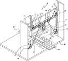
Translated fromKorean도 1은 본 발명에 따른 와이어톱을 이용한 커팅장치의 개략적인 정면사시도1 is a schematic front perspective view of a cutting device using a wire saw according to the present invention
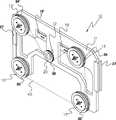
도 2는 본 발명에 따른 와이어톱을 이용한 커팅장치의 개략적인 배면사시도Figure 2 is a schematic rear perspective view of a cutting device using a wire saw according to the present invention
도 3은 본 발명에 따른 와이어톱을 이용한 커팅장치의 정면작동도Figure 3 is a front operation of the cutting device using a wire saw according to the invention
도 4는 본 발명에 따른 외이어톱을 이용한 커팅장치의 배면 작동도Figure 4 is a back operation of the cutting device using a wire saw according to the invention
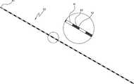
도 5는 본 발명에 따른 커팅장치에 사용되는 와이어톱의 확대단면도5 is an enlarged cross-sectional view of a wire saw used in a cutting device according to the present invention;
[도면 중 주요부분에 대한 부호][Signs for Main Parts of Drawings]
10 : 커팅장치 11 : 판10 cutting device 11: plate
12 : 조절홈 13,13' : 고정롤러12: adjusting
14,14' : 안내홈 15,15' : 고정롤러14,14 ':
16, 16' : 안내홈 17 : 가이드롤러16, 16 ': guide groove 17: guide roller
18,18' : 안내홈 19,19' : 브라켓18,18 ':
20 : 조절롤러 21 : 타임벨트20: adjusting roller 21: time belt
22 22' : 가이드22 22 ': Guide
23 : 브라켓 24 : 스플라인23: bracket 24: spline
25: 승하강구동부 26 : 고정구25: up and down driving unit 26: fixture
27 : 직선베어링 28 : 직선베어링가이드27: straight bearing 28: straight bearing guide
29 : 수직프레임 31,31' : 자바라식 전후구동부29:
32,32',32" : 베드 33 : 하부프레임32,32 ', 32 ": Bed 33: Lower frame
34,34',35,35',36 : 와이어안내홈34,34 ', 35,35', 36: Wire guide groove
40 : 와이어톱 41 : 절단부40: wire saw 41: cutting part
42 : 다이아절단부 43 : 다이아몬드42: diamond cutting 43: diamond
44 : 와이어44: wire
본 발명은 와이어톱을 이용한 커팅장치에 관한 것으로서, 더욱 상세하게는 좌우에 직선베어링가이드를 수직으로 설치하며 주모터에 볼베어링이 장착된 스플라인을 장착하여 승하강구동을 시키고 자바라식 전후구동부를 사용하여 베드를 전후로 구동시키며 절단부와 다이아전착절단부를 차례로 끼워 삽입한 와이어톱을 사용함으로써 모재를 원하는 치수만큼 고정밀로 절단시키며 비용을 절감할 뿐만 아니라 제조가 간편한 와이어톱을 이용한 커팅장치를 제공함에 있다.The present invention relates to a cutting device using a wire saw, and more specifically, to install a straight bearing guide vertically on the left and right, and mounted a spline equipped with a ball bearing on the main motor to drive up and down and use a bellows type front and rear drive unit. By using a wire saw driven back and forth by inserting the cutting part and the electrodeposition cutting part in turn, the cutting material is precisely cut to the desired dimensions and the cost is reduced, and the cutting device using the wire saw is easy to manufacture.
일반적으로 실리콘과 세라믹 등의 모재를 절단하는데 사용되는 와이어톱의 와이어는 유리분말 등의 절단용 슬러리를 절단부에 공급하면서 다수개의 와이어를 절단면에 통과시키는 와이어톱 및 피아노선 등의 와이어 표면에 다이아몬드 입자를 전착시킨 다이아몬드 전착와이어가 있다.Generally, wire saw wires used for cutting base materials such as silicon and ceramics have diamond particles on the wire surface such as wire saws and piano wires that pass a plurality of wires through the cutting surface while supplying a cutting slurry such as glass powder to the cutting portion. There is a diamond electrodeposition wire electrodeposited.
상기 슬러리를 이용한 외이어톱의 경우에는 절단작업 중 와이어의 단선이 발생하는 경우 전체가 불량으로 처리되는 큰 문제점이 있으며 원하는 치수로 절단하기 어려운 문제점이 있었다. 또한, 다이아몬드 전착와이어의 경우에는 와이어의 수명이 짧으며 제조에 많은 비용이 들며 그에 다른 장비도 고가로 유통되는 문제점이 있었다.In the case of the wire saw using the slurry, when a wire break occurs during the cutting operation, there is a big problem that the whole is treated as defective and difficult to cut to a desired dimension. In addition, in the case of diamond electrodeposition wire, the life of the wire is short, there is a lot of costs in manufacturing, and there is a problem that other equipment is also distributed at a high price.
본 발명은 상기한 바와 같은 문제점을 해결하기 위하여 발명된 것으로서 본 발명의 목적은 절단부와 다이아전착절단부를 차례로 끼워 삽입한 와이어톱을 사용함으로써 제조비용을 절감할 뿐만 아니라 제조가 간편한 와이어톱을 이용한 커팅장치를 제공함에 있다. 본 발명의 또 다른 목적은 직선베어링가이드를 수직으로 설치하며 주모터에 볼베어링이 장착된 스플라인을 장착하여 승하강구동을 시키고 자바라식 전후구동부를 사용하여 베드를 전후로 구동시킴으로써 모재를 원하는 치수만큼 고정밀로 절단시킬 수 있는 와이어톱을 이용한 커팅장치를 제공함에 있다.The present invention has been invented to solve the problems described above, the object of the present invention is to use a wire saw inserted by inserting the cutting portion and the electrodeposition cutting portion in turn to reduce the manufacturing cost as well as cutting using a simple wire saw In providing a device. Yet another object of the present invention is to install the linear bearing guide vertically and to mount the spline equipped with a ball bearing to the main motor to drive up and down, and to drive the bed back and forth using the bellows type front and rear drive unit with high precision to the desired dimensions To provide a cutting device using a wire saw that can be cut.
이하, 본 발명에 의한 와이어톱을 이용한 커팅장치를 첨부된 도면에 의거하여 상세히 살펴본다.Hereinafter, a cutting device using a wire saw according to the present invention will be described in detail with reference to the accompanying drawings.
도 1은 본 발명에 따른 와이어톱을 이용한 커팅장치의 개략적인 정면사시도, 도 2는 커팅장치의 개략적인 배면사시도이며, 도 3은 커팅장치의 정면작동도, 도 4는 커팅장치의 배면 작동도이고, 도 5는 본 발명에 따른 커팅장치에 사용되는 와이어톱의 확대단면도이다.1 is a schematic front perspective view of a cutting device using a wire saw according to the present invention, Figure 2 is a schematic rear perspective view of the cutting device, Figure 3 is a front operation of the cutting device, Figure 4 is a rear operation of the cutting device. 5 is an enlarged cross-sectional view of a wire saw used in a cutting device according to the present invention.
본 발명에 의한 와이어톱을 이용한 커팅장치(10)는 중앙부에 조절홈(12)이 형성된 판(11)과; 상기 판(11)의 상부 모서리 쪽으로 설치되는 고정롤러(13)(13')와; 상기 판(11)의 하부 모서리 쪽으로 설치되는 고정롤러(15)(15')와; 상기 고정롤러(13)(13')의 사이에 각각 장착되어 형성된 브라켓(19)(19')에 설치되는 가이드롤러(17)(17')와; 상기 브라켓(19)(19') 사이에 형성된 상기 조절홈(12)내에 설치되는 조절롤러(20)와; 상기 판(11)의 타측면 상부에 부착되어 형성된 승하강구동부(25)와; 상기 승하강구동부(25)의 내부에 삽입되어 주모터와 연결되는 스플라인(24)과; 상기 스플라인(24)의 하단부에 삽입되어 고정되는 고정구(26)와; 상기 판(11)의 양측에 결합되어 형성된 직선베어링(27)과; 상기 직선베어링(27)과 맞닿여 승하강구동을 가능케 하는 직선베어링가이드(28)와; 상기 직선베어링가이드(28)을 지지해주는 수직프레임(29)과; 일측과 타측으로 자바라식 전후구동부(31)가 설치되고 상기 전후구동부(31) 사이에 베드(32)가 형성된 하부프레임(33)과; 와이어(44) 에 절단부(41)와 다이아절단부(42)가 차례로 삽입되어져 형성된 와이어톱(40);으로 구성되어 있다.
상기에 있어서 판(11)의 상부 모서리 쪽으로 설치되는 고정롤러(13)(13')의 경우에는 일측에 와이어 안내홈(34)(34')이 형성되어 있어 고정롤러(13)(13')의 회전시 와이어톱(40)의 이동을 용이하게 하는 구조이며 상기 판(11)의 하부 모서리 쪽으로 설치되는 고정롤러(15)(15') 또한 일측에 와이어 안내홈(35)(35')이 형성되어 있는 구조이다.In the above, in the case of the
또한, 상기 판(11)의 중앙부에 형성된 조절홈(12)에 결합된 조절롤러(20)의 일측에도 와이어안내홈(36)이 형성되어 있는 구조로써 상기 고정롤러(13)(13')(15)(15')의 와이어 안내홈(34)(34')(35)(35')이 와이어톱(40)의 이동을 용이하게 하는 구조인 반면에 상기 조절롤러(20)의 와이어안내홈(36)은 와이어톱(40)의 텐션을 조절하게 하는 구조이다.In addition, the fixed rollers (13, 13 ') (with a structure in which a wire guide groove (36) is formed at one side of the adjusting roller (20) coupled to the adjusting groove (12) formed at the center of the plate (11). The wire guide grooves 34, 34 ', 35 and 35' of the 15 and 15 'are designed to facilitate the movement of the wire saw 40, while the wire guide grooves of the adjusting
즉, 상기 조절롤러(15)가 상하로 이동함으로써 와이어톱(40)의 텐션을 조절하는 구조로써 모재의 재질에 따라 조절롤러(15)의 위치가 다르게 조절되는데 이는 모재의 절단작업시 절단마찰력보다 와이어텐션이 강해야만 절단작업이 가능하기 때문이며 절단마찰력이 와이어텐션보다 강하게 되면 절단작업은 불가능하며 이때 상기 고정롤러(13)(13')(15)(15')들은 공회전만 하게 되는 것이다.That is, the
이때, 상기 판(11)의 상부 모서리 쪽으로 설치되는 고정롤러(13)(13')의 타측에는 안내홈(14)(14')이 2단으로 형성되어 있으며 상기 판(11)의 하부 모서리 쪽으로 설치되는 고정롤러(15)(15')의 타측에는 안내홈(16)(16')이 1단으로 형성되어 있다. 또한, 상기 고정롤러(13)(13')의 사이에 각각 장착되어 형성된 브라켓(19)(19')에 설치되는 가이드롤러(17)(17')의 타측에도 안내홈(18)(18')이 1단으로 형성되어 있는 구조이다.At this time, the
상기한 각각 롤러의 안내홈들은 타임벨트(21)로 연결되어 있는데, 우측에 형성된 두 개의 고정롤러(13)(15)와 가이드롤러(17)의 각각 안내홈(14)(16)(18)을 따라 타임벨트(21)가 회전되는 구조이고, 좌측에 형성된 두개의 고정롤러(13')(15')와 가이드롤러(17')의 각각 안내홈(14')(16')(18')을 따라 타임벨트(21)가 회전되며, 상부에 형성된 두개의 고정롤러(13)(13')의 또 다른 안내홈(14)(14')을 따라 타임벨트(21)가 회전되는 구조로 이루어져 있다.Each of the guide grooves of the rollers is connected to the
상기 고정롤러(15')에 부착된 모터(미도시)가 구동하게 되면 좌측에 형성된 두개의 고정롤러(13')(15')와 가이드롤러(17')의 각각 안내홈(14')(16')(18')을 따라 타임벨트(21)가 회전하면서 고정롤러(13')가 회전됨으로써 상부에 형성된 두개의 고정롤러(13)(13')의 또 다른 안내홈(14)(14')을 따라 타임벨트(21)가 회전되고 상기 고정롤러(13)가 회전함으로써 다시 우측에 형성된 두개의 고정롤러(13)(15)와 가이드롤러(17)의 각각 안내홈(14)(16)(18)을 따라 타임벨트(21)가 회전되는 구조 로 이루어져 있다.When the motor (not shown) attached to the fixed roller 15 'is driven, the guide grooves 14' of the two fixed rollers 13 'and 15' and the guide roller 17 'formed on the left side respectively ( As the
상기 판(11)의 우측면 타측 상부에 부착되어 형성된 승하강구동부(25)에는 주모터(미도시)와 연결되는 스플라인(24)이 내부로 삽입되어 형성되고 상기 스플라인(24)의 하단부에는 고정구(26)가 수직프레임(29)에 고정되어 형성된 구조이다. 또한 상기 판(11)의 양측에 결합되어 형성된 직선베어링(27)은 직선베어링가이드(28)와 맞닿여 승하강구동이 가능한 구조이고 상기 직선베어링가이드(28)는 수직프레임(29)에 의해 지지되고 있는 구조이다.The
주모터(미도시)가 구동하게 되면 스플라인(24)이 회전하면서 스플라인(24)과 볼베어링(미도시)으로 결합된 승하강구동부(25)가 이동하게 되어 상기 승하강구동부(25)와 결합된 판(11)자체가 양측에 결합되어 형성된 직선베어링(27)이 직선베어링가이드(28)와 맞닿여서 위 아래로 움직이게 되는 구조로써 이는 정밀한 속도제어가 가능하며 좌우 흔들림없이 부드럽게 이동가능한 구조이다.When the main motor (not shown) is driven, as the
상기 수직프레임(29)의 하단면에 결합되어 형성된 하부프레임(33)에는 일측과 타측으로 자바라식 전후구동부(31)가 설치되고 상기 자바라식 전후구동부(31) 사이에 베드(32)가 형성된 구조로 이루어져 있다.The
이는 하부프레임(33)의 타측으로 형성된 구동장치(미도시)에 의해 자바라식 전후구동부(31)와 베드(32)가 구동하게 되는 구조인데 상기 구동장치(미도시)는 컨트롤박스(미도시)와 연결되어 있어 모재의 절단작업시 정밀하게 위치제어가 가능한 구조이다.This is a structure in which the bellows type front and
상기 각 고정롤러(13)(13')(15)(15')와 조절롤러(15)의 각각 안내홈(34)(34')(35)(35')(36)에 의해 회전이동하는 와이어톱(40)은 와이어(44)에 절단부(41)와 다이아절단부(42)가 차례로 삽입되어져 형성된 구조로써 상기 다이아절단부(42)는 상기 절단부(41)에 다이아몬드(43)가 전착의 방식으로 결합되어 있으며, 상기 절단부(41)와 다이아절단부(42)사이의 간극은 모재의 절단작업시 칩(찌꺼기)의 배출을 용이하게 하는 구조이다.Each of the
이상과 같이 본 발명에 따른 와이어톱을 이용한 커팅장치는 절단부와 다이아전착절단부를 차례로 끼워서 삽입한 와이어톱을 사용함으로써 제조비용을 절감할 뿐만 아니라 제조가 간편한 이점이 있고, 직선베어링가이드를 좌우에 수직으로 설치하고 주모터에 볼베어링이 장착된 스플라인을 장착하여 승하강구동을 시킴으로써 정밀한 속도제어가 가능하며 좌우 흔들림없이 부드럽게 이동가능한 이점이 있으며, 자바라식전후구동부를 사용하여 베드를 전후로 구동시킴으로써 모재를 원하는 치수만큼 고정밀로 절단시킬 수 있는 위치제어가 가능한 이점이 있다.As described above, the cutting device using the wire saw according to the present invention reduces the manufacturing cost by using the wire saw inserted by inserting the cutting part and the electrodeposition cutting part in turn, and has the advantage of easy manufacturing, and the linear bearing guide is vertical to the left and right. It is possible to precisely control speed by moving up and down by installing spline equipped with ball bearing on the main motor and moving smoothly without shaking left and right, and using the bellows front and rear drive unit to drive the bed back and forth There is an advantage that the position control capable of cutting with high precision as the dimension is possible.
Claims (1)
Translated fromKoreanPriority Applications (1)
| Application Number | Priority Date | Filing Date | Title |
|---|---|---|---|
| KR1020060000186AKR100649444B1 (en) | 2006-01-02 | 2006-01-02 | Cutting device using wire saw |
Applications Claiming Priority (1)
| Application Number | Priority Date | Filing Date | Title |
|---|---|---|---|
| KR1020060000186AKR100649444B1 (en) | 2006-01-02 | 2006-01-02 | Cutting device using wire saw |
Related Child Applications (1)
| Application Number | Title | Priority Date | Filing Date |
|---|---|---|---|
| KR2020060000070UDivisionKR200413150Y1 (en) | 2006-01-02 | 2006-01-02 | Cutting device using wire saw |
Publications (2)
| Publication Number | Publication Date |
|---|---|
| KR20060006856A KR20060006856A (en) | 2006-01-19 |
| KR100649444B1true KR100649444B1 (en) | 2006-11-28 |
Family
ID=37118393
Family Applications (1)
| Application Number | Title | Priority Date | Filing Date |
|---|---|---|---|
| KR1020060000186AExpired - Fee RelatedKR100649444B1 (en) | 2006-01-02 | 2006-01-02 | Cutting device using wire saw |
Country Status (1)
| Country | Link |
|---|---|
| KR (1) | KR100649444B1 (en) |
Cited By (2)
| Publication number | Priority date | Publication date | Assignee | Title |
|---|---|---|---|---|
| KR101013525B1 (en)* | 2008-03-13 | 2011-02-10 | 다이섹(주) | Cutting device using endless diamond wire |
| CN114654019A (en)* | 2022-05-19 | 2022-06-24 | 苏州博创熠鑫智造科技有限责任公司 | 3D prints formed part and base plate separator |
Families Citing this family (12)
| Publication number | Priority date | Publication date | Assignee | Title |
|---|---|---|---|---|
| KR101433750B1 (en) | 2009-08-14 | 2014-08-27 | 생-고뱅 어브레이시브즈, 인코포레이티드 | Abrasive articles including abrasive particles bonded to an elongated body, and methods of forming thereof |
| MX2012001810A (en) | 2009-08-14 | 2012-06-01 | Saint Gobain Abrasives Inc | ABRASIVE ITEMS THAT INCLUDE ABRASIVE PARTICLES UNITED TO A LONG BODY. |
| TWI466990B (en) | 2010-12-30 | 2015-01-01 | Saint Gobain Abrasives Inc | Abrasive article and forming method |
| CN107263340A (en) | 2011-09-16 | 2017-10-20 | 圣戈班磨料磨具有限公司 | abrasive article and forming method |
| WO2013049204A2 (en) | 2011-09-29 | 2013-04-04 | Saint-Gobain Abrasives, Inc. | Abrasive articles including abrasive particles bonded to an elongated substrate body having a barrier layer, and methods of forming thereof |
| TW201404527A (en) | 2012-06-29 | 2014-02-01 | Saint Gobain Abrasives Inc | Abrasive article and method of forming |
| TWI477343B (en) | 2012-06-29 | 2015-03-21 | Saint Gobain Abrasives Inc | Abrasive article and method of forming |
| TW201402274A (en) | 2012-06-29 | 2014-01-16 | Saint Gobain Abrasives Inc | Abrasive article and method of forming |
| TWI474889B (en) | 2012-06-29 | 2015-03-01 | Saint Gobain Abrasives Inc | Abrasive article and method of forming |
| TW201441355A (en) | 2013-04-19 | 2014-11-01 | Saint Gobain Abrasives Inc | Abrasive article and method of forming |
| CN103531991B (en)* | 2013-10-30 | 2016-02-03 | 东莞市三信精密机械有限公司 | One cuts module |
| TWI621505B (en) | 2015-06-29 | 2018-04-21 | 聖高拜磨料有限公司 | Abrasive article and forming method |
Citations (4)
| Publication number | Priority date | Publication date | Assignee | Title |
|---|---|---|---|---|
| JPH06182620A (en)* | 1992-12-17 | 1994-07-05 | Amada Co Ltd | Band sawing machine |
| JPH08118342A (en)* | 1994-10-20 | 1996-05-14 | Shingo Ogyu | Stone material curved surface cutter |
| JPH1076515A (en)* | 1996-09-02 | 1998-03-24 | Tawara Sekizaiten:Kk | Cutting method of hard material such as stone and cutting device |
| KR200385536Y1 (en)* | 2005-03-04 | 2005-05-31 | 김만영 | The connection device of wire saw to cut stone |
- 2006
- 2006-01-02KRKR1020060000186Apatent/KR100649444B1/ennot_activeExpired - Fee Related
Patent Citations (4)
| Publication number | Priority date | Publication date | Assignee | Title |
|---|---|---|---|---|
| JPH06182620A (en)* | 1992-12-17 | 1994-07-05 | Amada Co Ltd | Band sawing machine |
| JPH08118342A (en)* | 1994-10-20 | 1996-05-14 | Shingo Ogyu | Stone material curved surface cutter |
| JPH1076515A (en)* | 1996-09-02 | 1998-03-24 | Tawara Sekizaiten:Kk | Cutting method of hard material such as stone and cutting device |
| KR200385536Y1 (en)* | 2005-03-04 | 2005-05-31 | 김만영 | The connection device of wire saw to cut stone |
Cited By (2)
| Publication number | Priority date | Publication date | Assignee | Title |
|---|---|---|---|---|
| KR101013525B1 (en)* | 2008-03-13 | 2011-02-10 | 다이섹(주) | Cutting device using endless diamond wire |
| CN114654019A (en)* | 2022-05-19 | 2022-06-24 | 苏州博创熠鑫智造科技有限责任公司 | 3D prints formed part and base plate separator |
Also Published As
| Publication number | Publication date |
|---|---|
| KR20060006856A (en) | 2006-01-19 |
Similar Documents
| Publication | Publication Date | Title |
|---|---|---|
| KR100649444B1 (en) | Cutting device using wire saw | |
| US7895929B2 (en) | Blade driving mechanism for a table saw | |
| JP2014014903A (en) | Wire saw and workpiece processing method in the same | |
| JP2015033752A (en) | Wire saw | |
| CN217167862U (en) | Energy-saving slabstone edging machine with quick material loading function | |
| CN111347111A (en) | Wire cut electric discharge machine | |
| JP2012020390A (en) | Platy member polishing device | |
| JP2011167810A5 (en) | ||
| CN216066971U (en) | Stone plate conveying equipment for coarse grinding machine | |
| CN111993602A (en) | Stone bearing device and diamond wire stone cutting machine | |
| KR200413150Y1 (en) | Cutting device using wire saw | |
| CN110605487A (en) | Automatic material cutting equipment | |
| CN212498346U (en) | A stone bearing device and diamond wire stone cutting machine | |
| KR101691889B1 (en) | Wire saw cutting machine | |
| CN110076548B (en) | Recycling and reusing splitting machine for constructional engineering steel chain riveting | |
| CN219276285U (en) | Wire cutting device | |
| KR20100111119A (en) | Working jig for wire cut electric discharge machine | |
| CN214418493U (en) | A large size bar polishing equipment | |
| CN201105398Y (en) | A conveying and feeding device of a double-sided glass edging machine | |
| CN215919976U (en) | Automatic steel pipe deburring and polishing compound machine | |
| KR200358966Y1 (en) | Edge preparation machine | |
| CN212331460U (en) | Three-roll down-pressing stone diamond wire cutting machine | |
| CN116060787A (en) | A double chuck alternate automatic loading and unloading jig | |
| KR20040032482A (en) | Router | |
| CN219444737U (en) | Steel all-in-one of polishing |
Legal Events
| Date | Code | Title | Description |
|---|---|---|---|
| A201 | Request for examination | ||
| PA0109 | Patent application | St.27 status event code:A-0-1-A10-A12-nap-PA0109 | |
| PA0201 | Request for examination | St.27 status event code:A-1-2-D10-D11-exm-PA0201 | |
| PG1501 | Laying open of application | St.27 status event code:A-1-1-Q10-Q12-nap-PG1501 | |
| PN2301 | Change of applicant | St.27 status event code:A-3-3-R10-R13-asn-PN2301 St.27 status event code:A-3-3-R10-R11-asn-PN2301 | |
| D13-X000 | Search requested | St.27 status event code:A-1-2-D10-D13-srh-X000 | |
| D14-X000 | Search report completed | St.27 status event code:A-1-2-D10-D14-srh-X000 | |
| E701 | Decision to grant or registration of patent right | ||
| PE0701 | Decision of registration | St.27 status event code:A-1-2-D10-D22-exm-PE0701 | |
| GRNT | Written decision to grant | ||
| PR0701 | Registration of establishment | St.27 status event code:A-2-4-F10-F11-exm-PR0701 | |
| PR1002 | Payment of registration fee | St.27 status event code:A-2-2-U10-U11-oth-PR1002 Fee payment year number:1 | |
| PG1601 | Publication of registration | St.27 status event code:A-4-4-Q10-Q13-nap-PG1601 | |
| R18-X000 | Changes to party contact information recorded | St.27 status event code:A-5-5-R10-R18-oth-X000 | |
| PR1001 | Payment of annual fee | St.27 status event code:A-4-4-U10-U11-oth-PR1001 Fee payment year number:4 | |
| PR1001 | Payment of annual fee | St.27 status event code:A-4-4-U10-U11-oth-PR1001 Fee payment year number:5 | |
| FPAY | Annual fee payment | Payment date:20110826 Year of fee payment:6 | |
| PR1001 | Payment of annual fee | St.27 status event code:A-4-4-U10-U11-oth-PR1001 Fee payment year number:6 | |
| FPAY | Annual fee payment | Payment date:20120918 Year of fee payment:7 | |
| PR1001 | Payment of annual fee | St.27 status event code:A-4-4-U10-U11-oth-PR1001 Fee payment year number:7 | |
| LAPS | Lapse due to unpaid annual fee | ||
| PC1903 | Unpaid annual fee | St.27 status event code:A-4-4-U10-U13-oth-PC1903 Not in force date:20131118 Payment event data comment text:Termination Category : DEFAULT_OF_REGISTRATION_FEE | |
| PN2301 | Change of applicant | St.27 status event code:A-5-5-R10-R13-asn-PN2301 St.27 status event code:A-5-5-R10-R11-asn-PN2301 | |
| PC1903 | Unpaid annual fee | St.27 status event code:N-4-6-H10-H13-oth-PC1903 Ip right cessation event data comment text:Termination Category : DEFAULT_OF_REGISTRATION_FEE Not in force date:20131118 | |
| P22-X000 | Classification modified | St.27 status event code:A-4-4-P10-P22-nap-X000 | |
| P22-X000 | Classification modified | St.27 status event code:A-4-4-P10-P22-nap-X000 |