KR100641658B1 - Ink Cartridges for Printers - Google Patents
Ink Cartridges for PrintersDownload PDFInfo
- Publication number
- KR100641658B1 KR100641658B1KR1020050100724AKR20050100724AKR100641658B1KR 100641658 B1KR100641658 B1KR 100641658B1KR 1020050100724 AKR1020050100724 AKR 1020050100724AKR 20050100724 AKR20050100724 AKR 20050100724AKR 100641658 B1KR100641658 B1KR 100641658B1
- Authority
- KR
- South Korea
- Prior art keywords
- air
- ink
- chamber
- ink cartridge
- printer
- Prior art date
- Legal status (The legal status is an assumption and is not a legal conclusion. Google has not performed a legal analysis and makes no representation as to the accuracy of the status listed.)
- Expired - Fee Related
Links
Images


Classifications
- B—PERFORMING OPERATIONS; TRANSPORTING
- B41—PRINTING; LINING MACHINES; TYPEWRITERS; STAMPS
- B41J—TYPEWRITERS; SELECTIVE PRINTING MECHANISMS, i.e. MECHANISMS PRINTING OTHERWISE THAN FROM A FORME; CORRECTION OF TYPOGRAPHICAL ERRORS
- B41J2/00—Typewriters or selective printing mechanisms characterised by the printing or marking process for which they are designed
- B41J2/005—Typewriters or selective printing mechanisms characterised by the printing or marking process for which they are designed characterised by bringing liquid or particles selectively into contact with a printing material
- B41J2/01—Ink jet
- B41J2/17—Ink jet characterised by ink handling
- B41J2/175—Ink supply systems ; Circuit parts therefor
- B41J2/17503—Ink cartridges
- B41J2/17513—Inner structure
- B—PERFORMING OPERATIONS; TRANSPORTING
- B41—PRINTING; LINING MACHINES; TYPEWRITERS; STAMPS
- B41J—TYPEWRITERS; SELECTIVE PRINTING MECHANISMS, i.e. MECHANISMS PRINTING OTHERWISE THAN FROM A FORME; CORRECTION OF TYPOGRAPHICAL ERRORS
- B41J2/00—Typewriters or selective printing mechanisms characterised by the printing or marking process for which they are designed
- B41J2/005—Typewriters or selective printing mechanisms characterised by the printing or marking process for which they are designed characterised by bringing liquid or particles selectively into contact with a printing material
- B41J2/01—Ink jet
- B41J2/17—Ink jet characterised by ink handling
- B41J2/175—Ink supply systems ; Circuit parts therefor
- B41J2/17503—Ink cartridges
- B41J2/17506—Refilling of the cartridge
- B—PERFORMING OPERATIONS; TRANSPORTING
- B41—PRINTING; LINING MACHINES; TYPEWRITERS; STAMPS
- B41J—TYPEWRITERS; SELECTIVE PRINTING MECHANISMS, i.e. MECHANISMS PRINTING OTHERWISE THAN FROM A FORME; CORRECTION OF TYPOGRAPHICAL ERRORS
- B41J2/00—Typewriters or selective printing mechanisms characterised by the printing or marking process for which they are designed
- B41J2/005—Typewriters or selective printing mechanisms characterised by the printing or marking process for which they are designed characterised by bringing liquid or particles selectively into contact with a printing material
- B41J2/01—Ink jet
- B41J2/17—Ink jet characterised by ink handling
- B41J2/175—Ink supply systems ; Circuit parts therefor
- B41J2/17503—Ink cartridges
- B41J2/1752—Mounting within the printer
- B—PERFORMING OPERATIONS; TRANSPORTING
- B41—PRINTING; LINING MACHINES; TYPEWRITERS; STAMPS
- B41J—TYPEWRITERS; SELECTIVE PRINTING MECHANISMS, i.e. MECHANISMS PRINTING OTHERWISE THAN FROM A FORME; CORRECTION OF TYPOGRAPHICAL ERRORS
- B41J2/00—Typewriters or selective printing mechanisms characterised by the printing or marking process for which they are designed
- B41J2/005—Typewriters or selective printing mechanisms characterised by the printing or marking process for which they are designed characterised by bringing liquid or particles selectively into contact with a printing material
- B41J2/01—Ink jet
- B41J2/17—Ink jet characterised by ink handling
- B41J2/175—Ink supply systems ; Circuit parts therefor
- B41J2/17596—Ink pumps, ink valves
- B—PERFORMING OPERATIONS; TRANSPORTING
- B41—PRINTING; LINING MACHINES; TYPEWRITERS; STAMPS
- B41J—TYPEWRITERS; SELECTIVE PRINTING MECHANISMS, i.e. MECHANISMS PRINTING OTHERWISE THAN FROM A FORME; CORRECTION OF TYPOGRAPHICAL ERRORS
- B41J2/00—Typewriters or selective printing mechanisms characterised by the printing or marking process for which they are designed
- B41J2/005—Typewriters or selective printing mechanisms characterised by the printing or marking process for which they are designed characterised by bringing liquid or particles selectively into contact with a printing material
- B41J2/01—Ink jet
- B41J2/17—Ink jet characterised by ink handling
- B41J2/19—Ink jet characterised by ink handling for removing air bubbles
Landscapes
- Ink Jet (AREA)
Abstract
Translated fromKoreanDescription
Translated fromKorean도1은 일반적인 프린터를 나타낸 사시도.1 is a perspective view showing a general printer.
도2는 종래의 잉크 카트리지를 나타낸 단면도.2 is a cross-sectional view showing a conventional ink cartridge.
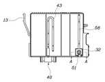
도3은 본 발명에 따른 잉크 카트리지를 나타낸 분해 사시도.Figure 3 is an exploded perspective view showing the ink cartridge according to the present invention.
도4는 본 발명에 따른 잉크 카트리지를 나타낸 단면도.4 is a sectional view of an ink cartridge according to the present invention;
도5는 본 발명에 따른 잉크 카트리지의 잉크 배출과정을 설명하기 위한 단면도.5 is a cross-sectional view for explaining an ink discharge process of the ink cartridge according to the present invention.
※도면의 주요부분에 대한 부호의 설명※※ Explanation of symbols about main part of drawing ※
10 : 몸체11 : 충전홈10: body 11: filling groove
13 : 고정암20 : 격벽13: fixed arm 20: bulkhead
21 : 연결홈30 : 충전챔버21: connecting groove 30: charging chamber
31 : 배출챔버32 : 공기챔버31: discharge chamber 32: air chamber
40 : 잉크배출구41 : 패킹부재40: ink discharge port 41: packing member
43 : 잉크 이동홈50 : 공기흡입 밸브43: ink moving groove 50: air suction valve
55 : 공기 이동홈56 : 공기 유도홈55: air moving groove 56: air guide groove
60 : 차단필름70 : 커버60: blocking film 70: cover
본 발명은 프린터용 잉크 카트리지에 관한 것으로서, 더욱 상세하게는 잉크가 충입되는 공간을 확장함은 물론, 잉크의 유동으로 인한 기포 및 잉크의 역류 발생을 방지할 수 있는 프린터용 잉크 카트리지에 관한 것이다.The present invention relates to an ink cartridge for a printer. More particularly, the present invention relates to an ink cartridge for a printer that can expand a space in which ink is filled, as well as prevent air bubbles and back flow of ink due to the flow of ink.
일반적으로 컴퓨터에서 작성된 각종 문서 또는 그림을 종이에 출력하는 장치로 프린터가 사용되고 있으며, 그 프린터는 도트식 프린터, 잉크젯 프린터 및 레이져 프린터 등이 있으며, 상기 잉크젯 프린터는 도1에 나타낸 바와 같이 프린터(100)의 내부에 카트리지운반대(110)가 이동 가능하게 설치되어 있고, 그 카트리지운반대(110)에는 잉크가 충전되는 잉크 카트리지(120)가 착탈되는 공간을 가지며, 잉크 카트리지(120)에 충입된 잉크를 흡입하는 니들(111)이 설치되어 있고, 상기 니들을 통하여 잉크를 토출하는 헤드(112)로 잉크를 이송하게 된다.In general, a printer is used as a device for outputting various documents or drawings created on a computer on paper, and the printer includes a dot printer, an ink jet printer, a laser printer, and the like. The
상기 잉크카트리지는 프린터의 종류에 따라 그 모양 및 구조를 다르나, 일반적으로 1에 나타낸 바와 같이 프린터에 설치할 수 있도록 소정의 크기를 갖으며 내부에는 수용부(201)가 형성된 몸체(200)가 마련되어 있고, 그 몸체(200)의 일 측면에는 프린터부의 카트리지운반대(110)에 고정할 수 있는 고정암(202)이 연장되게 형성되어 있다.The ink cartridge is different in shape and structure depending on the type of printer, but generally has a predetermined size so that it can be installed in the printer as shown in 1 and the
한편, 몸체(200)에 형성된 수용부(201)에는 잉크가 함침되는 스폰지(210)가 내장되어 있고, 몸체(200)의 저면에는 스폰지(210)에 함침된 잉크가 배출되는 배출구(220)가 형성되어 있되, 잉크배출구(220) 내부에는 잉크흡입 니들(111)과 결합하여 잉크의 흐름을 방지할 수 있는 패킹부재(205)가 설치되어 있다.On the other hand, the
그리고 상기 몸체(200)의 상면 선택된 곳에는 외부 공기를 몸체(200)의 내부로 공급하기 위한 통공(203)이 형성되어 있다.In addition, the selected portion of the upper surface of the
따라서, 프린터(100)를 작동시키면, 프린터 제어부의 전기적 신호에 의해 카트리지운반대(110)가 이동되면서 헤드(112)로부터 잉크를 토출하여 문서 또는 그림을 프린팅하게 되는 것으로서, 연속적으로 수용부(201)에 있는 잉크가 잉크배출구(220) 및 잉크흡입니들(111)을 통하여 헤드로 잉크를 공급되게 되어 연속적인 프린팅이 가능하게 된다.Therefore, when the
그러나 이러한 종래의 잉크 카트리지는 몸체(200)의 내부에 잉크가 함침되는 스폰지(210)가 내장되어 있으므로 잉크를 충입할 수 있는 공간이 축소되었음은 물론, 상기 스폰지(210)를 몸체(200)에 내장시키는 공정이 추가되므로 단가가 상승되는 문제점이 있었다.However, since the conventional ink cartridge has a
이러한 문제점을 해결하기 위하여 몸체(200)의 내부에 스폰지(210)를 제거하는 경우도 있으나, 이때에는 카트리지 내부의 일정한 압력을 유지하기 어려울뿐만 아니라, 잉크 카트리지가 헤드(110)에 설치된 상태에서 이동될 때 잉크가 유동됨으로 인하여 되어 상기 잉크에 미세한 기포가 발생되고, 그 기포가 잉크와 함께 배출구(220)로 배출되어 출력물의 품질을 저하시키는 문제점이 있었다.In order to solve this problem, there is a case in which the
또한, 잉크가 유동됨으로 인하여, 잉크카트리지 몸체(200)내부의 일부 공간에 음압이 생겨, 잉크흡입니들(111)이나 헤드(112)에 차 있는 잉크가 역류하여, 프린터 제어부의 출력신호에도 불구하고 잉크가 토출되지 못하여 출력물의 품질을 저하시키는 등의 문제점이 있었다.In addition, due to the flow of the ink, a negative pressure is generated in a portion of the interior of the
본 발명은 상기한 문제점을 해결하기 위하여 발명한 것으로서, 그 목적은 잉크가 충입되는 몸체의 내부에 복수개의 격벽을 형성하여 내부 공간을 복수개의 챔버로 구분하고, 잉크배출구와 잉크이동홈을 매개로 연결되는 잉크배출챔버를 두어 카트리지 내부압력을 일정하게 유지시켜 우수한 출력물을 얻을 수 있는 저렴한 프린터용 잉크 카트리지를 제공함에 있다.The present invention has been invented to solve the above problems, the object of which is to form a plurality of partitions in the interior of the body filled with ink to divide the internal space into a plurality of chambers, through the ink outlet and the ink moving groove An ink cartridge for an inexpensive printer can be obtained by having a connected ink discharge chamber to maintain a constant internal pressure of the cartridge to obtain excellent output.
상기 목적을 달성하기 위한 본 발명의 특징적인 구성을 설명하면 다음과 같다.Referring to the characteristic configuration of the present invention for achieving the above object is as follows.
본 발명의 프린터용 잉크 카트리지는 소정의 크기로 형성되고 상면에는 충전홈이 형성된 몸체와, 상기 몸체의 내부에 연결홈을 갖는 격벽에 의해서 분할된 복수개의 충전챔버와, 상기 충전챔버와 연결된 배출챔버와, 상기 배출챔버에 잉크 이동홈을 매개로 연결된 배출구와, 상기 충전챔버에 공기를 공급하도록 공기 이동홈을 매개로 연결된 공기챔버와, 상기 공기챔버에 설치된 공기흡입밸브와, 상기 공기흡입 밸브로 외부 공기를 유도하는 공기 유도홈과, 상기 몸체의 일면에 부착된 차단판과, 상기 몸체의 타면에 설치된 커버필름을 포함하여서 된 것이다.The ink cartridge for a printer of the present invention is formed in a predetermined size and has a filling groove formed on an upper surface thereof, a plurality of filling chambers divided by a partition wall having a connecting groove inside the body, and an discharge chamber connected to the filling chamber. A discharge port connected to the discharge chamber through the ink moving groove, an air chamber connected through the air moving groove to supply air to the filling chamber, an air suction valve installed in the air chamber, and the air suction valve. It includes an air guide groove for inducing outside air, a blocking plate attached to one side of the body, and a cover film installed on the other side of the body.
이와 같은 특징을 갖는 본 발명을 상세하게 설명하면 다음과 같다.Referring to the present invention having such characteristics in detail as follows.
도 3은 본 발명에 따른 잉크 카트리지를 나타낸 분해 사시도이고, 도4는 본 발명에 따른 잉크 카트리지를 나타낸 단면도이고, 도5는 본 발명에 따른 잉크 카트리지의 잉크 배출과정을 설명하기 위한 단면도이다.3 is an exploded perspective view showing an ink cartridge according to the present invention, FIG. 4 is a sectional view showing an ink cartridge according to the present invention, and FIG. 5 is a sectional view for explaining an ink ejection process of the ink cartridge according to the present invention.
여기에서 참조되는 바와 같이 본 발명은 소정의 크기로 형성된 몸체(10)가 마련되어 있고, 그 몸체(10)의 상면에는 잉크를 주입하기 위한 충전홈(11)이 형성되어 있으며, 잉크 충전후 상기 충전홈(11)은 고무마개(12)에 의해서 차단되어 있고, 상기 몸체(10)의 외부 측면에는 프린터에 설치된 헤드에 결합시 고정력이 발생되도록 고정암(13)이 형성되어 있다.As referred to herein, the present invention is provided with a
상기 몸체(10)의 내부공간은 격벽(20)에 의해서 복수개의 충전챔버(30)로 분할되어 있되, 상기 격벽(20)에는 각 충전챔버(30)가 통하여 지도록 연결홈(21)이 형성되어 있다.The inner space of the
한편, 상기 격벽(20)은 적어도 1개 이상을 설치하는 것이 바람직하고, 그 격벽(20)은 충전챔버(30)가 다단으로 형성되도록 수평방향으로 형성하는 것이 바람직하며, 상기 몸체(10)의 내부에는 최 하단의 충전챔버(30)와 연결된 배출챔버(31)가 형성되어 있다.On the other hand, it is preferable that at least one
그리고 상기 몸체(10)의 저면에는 잉크를 외부로 배출시키는 배출구(40)가 형성되어 있되, 그 배출구(40)의 내부에는 잉크흡입 니들(111)과 결합하여 잉크의 흐름을 방지할 수 있는 고무패킹(41)이 설치되어 있다.And the bottom surface of the
또한, 상기 배출챔버(31)와 배출구(40)는 잉크 이동홈(43)을 매개로 연결되어 있되, 상기 잉크 이동홈(43)은 몸체(10)의 외부 일면에 형성되어 있고, 그 잉크 이동홈(43)의 상단부는 최 상단에 형성된 충전챔버(30)의 상부 보다 높게 형성하는 것이 바람직하다.In addition, the
한편, 상기 몸체(10)의 내부에는 공기챔버(32)가 형성되어 있되, 그 공기챔 버(32)와 충전챔버(30)는 공기 이동홈(55)을 매개로 연결되어 있다.On the other hand, the inside of the
그리고 상기 공기챔버(32)에는 공기흡입 밸브(50)가 설치되어 있되, 그 공기흡입 밸브(50)는 외부의 공기는 흡입되고 내부의 잉크는 배출되지 않도록 일 방향으로만 개방되는 체크밸브를 설치하는 것이 바람직하다.And the
즉, 공기흡입 밸브는 공기챔버(32)의 측면에 복수개의 리브(51)가 형성되고 그 리브(51)의 중앙의 빈 공간으로 끝부분이 볼록한 압정형태의 공기흡입밸브(50)가 설치된다.That is, in the air intake valve, a plurality of
또한, 상기 몸체(10)의 외부 일면에는 공기흡입 밸브(50)로 외부 공기를 유도하는 공기 유도홈(56)이 형성되어 있되, 상기 공기 유도홈(56)의 상단부는 최 상단에 형성된 충전챔버(30)의 상부 보다 높게 형성하는 것이 바람직하고 상기 공기 유도홈(56)의 단부는 몸체(10)의 상면에 관통되게 형성되어 있다.In addition, the outer surface of the
그리고 상기 몸체(10)의 일면에는 잉크 이동홈(43) 및 공기 유도홈(56)의 측면을 차단하기 위한 차단필름(60)이 설치되어 있고, 몸체(10)의 타면에는 충전챔버(30), 배출챔버(31) 및 공기챔버(32)를 차단하기 위한 커버(70)가 설치되어 있다.And a blocking
이와 같이 구성된 본 발명을 상세히 설명하면 다음과 같다.Referring to the present invention configured as described in detail as follows.
먼저, 몸체(10)의 내부에 잉크를 충전할 때에는 충전홈(11)을 통하여 잉크를 주입하면 상기 잉크는 연결홈(21)에 의해서 연결되어 있는 복수개의 충전챔버(30)및 배출챔버(31)에 충입되는 것이고, 잉크 충입이 완료되면, 충전홈(11)이 차단되도록 고무마개(12)를 부착한다.First, when the ink is filled in the interior of the
이러한 상태에서 잉크 카트리지를 프린터(100)의 헤드(110)에 설치하면 상기 몸체(10)의 측면에 형성된 고정암(13)이 헤드에 결합되면서 몸체(10)의 유동을 방지하게 되는 것이고, 상기 몸체(10)에 형성된 배출구(40)는 카트리지 운반대(110)에 설치된 잉크흡입니들(111)에 결합된다.In this state, when the ink cartridge is installed in the
이러한 상태에서 프린터를 작동시키면 상기 잉크흡입니들(111)에 흡입력이 작용하게 되므로 배출챔버(31)에 저장된 잉크는 잉크 이동홈(43)을 통하여 배출구(40)로 이동되게 된다.When the printer is operated in this state, suction force is applied to the
한편 상기 잉크 이동홈(43)의 상단부는 충전챔버(30) 보다 높게 형성되어 있으므로 흡입력에 의해서만 이동되어 잉크가 과다하게 배출되는 것을 방지하게 되는 것이다.On the other hand, since the upper end of the
또한 상기 몸체(10)의 내부는 복수개의 충전챔버(30)로 분할 되어 있으므로 몸체(10)가 헤드(110)와 함께 이동될 때 충전챔버(30)에 충전된 잉크의 유동이 최소화되므로 잉크에 미세한 기포가 발생되는 것이 방지되고, 또한, 잉크가 유동됨으로 인하여, 잉크카트리지 몸체(200)내부의 일부 공간에 음압이 생겨, 잉크흡입니들(111)이나 헤드(112)에 차 있는 잉크가 역류하는 것이 방지되는 것이다.In addition, since the inside of the
그리고 상기 잉크가 배출되면 내부의 압력이 낮아지게 되고 상기 압력이 낮아짐에 따라서 공기챔버(32)에 설치된 공기흡입 밸브(50)가 개방되면서 공기 유도홈(56)을 통하여 공기가 유입된다.When the ink is discharged, the internal pressure is lowered, and as the pressure is lowered, air is introduced through the
이와 같이 본 발명은 몸체의 내부에 스펀지를 제거하여 내부공간을 증가시키면서도 카트리지 내부의 압력을 일정하게 유지할 수 있는 특유의 효과가 있다. 또 한 잉크 유동에 의한 기포 발생을 방지하고, 잉크의 유동에 의한 카트리지 내부에 순간적으로 압력이 낮아지는 것을 방지하여 잉크의 역류를 방지함으로써 출력물의 품질을 향상시킬 수 있게 되는 특유의 효과가 있다.As such, the present invention has a unique effect of maintaining the pressure inside the cartridge while increasing the internal space by removing the sponge inside the body. In addition, there is a unique effect of preventing the generation of bubbles due to the ink flow, and prevent the back flow of the ink by preventing the pressure is temporarily lowered inside the cartridge due to the flow of the ink to improve the quality of the output.
또한 본 발명은 몸체의 내부 압력에 의해서 공기가 공급되도록 공기챔버에 공기흡입 밸브가 설치되어 있으므로, 잉크가 외부로 누출되는 것을 미연에 방지할 수 있게 되는 효과가 있다.In addition, the present invention is provided with an air intake valve in the air chamber so that the air is supplied by the internal pressure of the body, there is an effect that can be prevented in advance to leak the ink to the outside.
Claims (12)
Translated fromKoreanPriority Applications (6)
| Application Number | Priority Date | Filing Date | Title |
|---|---|---|---|
| KR1020050100724AKR100641658B1 (en) | 2005-10-25 | 2005-10-25 | Ink Cartridges for Printers |
| AT06812225TATE552117T1 (en) | 2005-10-25 | 2006-10-25 | INK CARTRIDGE FOR PRINTER |
| EP06812225AEP1940627B1 (en) | 2005-10-25 | 2006-10-25 | An ink-cartridge for printers |
| PCT/KR2006/004383WO2007049919A1 (en) | 2005-10-25 | 2006-10-25 | An ink-cartridge for printers |
| US12/091,496US8128211B2 (en) | 2005-10-25 | 2006-10-25 | Ink-cartridge for printers |
| CN2006800435581ACN101312831B (en) | 2005-10-25 | 2006-10-25 | An ink-cartridge for printers |
Applications Claiming Priority (1)
| Application Number | Priority Date | Filing Date | Title |
|---|---|---|---|
| KR1020050100724AKR100641658B1 (en) | 2005-10-25 | 2005-10-25 | Ink Cartridges for Printers |
Publications (1)
| Publication Number | Publication Date |
|---|---|
| KR100641658B1true KR100641658B1 (en) | 2006-11-10 |
Family
ID=37653676
Family Applications (1)
| Application Number | Title | Priority Date | Filing Date |
|---|---|---|---|
| KR1020050100724AExpired - Fee RelatedKR100641658B1 (en) | 2005-10-25 | 2005-10-25 | Ink Cartridges for Printers |
Country Status (2)
| Country | Link |
|---|---|
| KR (1) | KR100641658B1 (en) |
| CN (1) | CN101312831B (en) |
Citations (1)
| Publication number | Priority date | Publication date | Assignee | Title |
|---|---|---|---|---|
| KR20030069599A (en)* | 2002-02-22 | 2003-08-27 | 삼성전자주식회사 | Ink cartridge for ink jet printer |
Family Cites Families (5)
| Publication number | Priority date | Publication date | Assignee | Title |
|---|---|---|---|---|
| US6243117B1 (en)* | 1995-05-12 | 2001-06-05 | Lexmark International, Inc. | Print head cartridge and method of making a print head cartridge by one-shot injection molding |
| JP4314702B2 (en)* | 1998-11-26 | 2009-08-19 | セイコーエプソン株式会社 | Printing apparatus, writing method, and printer |
| CA2469450C (en)* | 2000-10-20 | 2010-02-23 | Seiko Epson Corporation | Ink cartridge for ink jet recording device |
| US6817707B1 (en)* | 2003-06-18 | 2004-11-16 | Lexmark International, Inc. | Pressure controlled ink jet printhead assembly |
| CN2726881Y (en)* | 2004-09-06 | 2005-09-21 | 聂瑞权 | inkjet printer cartridge |
- 2005
- 2005-10-25KRKR1020050100724Apatent/KR100641658B1/ennot_activeExpired - Fee Related
- 2006
- 2006-10-25CNCN2006800435581Apatent/CN101312831B/ennot_activeExpired - Fee Related
Patent Citations (1)
| Publication number | Priority date | Publication date | Assignee | Title |
|---|---|---|---|---|
| KR20030069599A (en)* | 2002-02-22 | 2003-08-27 | 삼성전자주식회사 | Ink cartridge for ink jet printer |
Also Published As
| Publication number | Publication date |
|---|---|
| CN101312831B (en) | 2010-07-28 |
| CN101312831A (en) | 2008-11-26 |
Similar Documents
| Publication | Publication Date | Title |
|---|---|---|
| KR100855544B1 (en) | Ink-Cartridge for printers and ink refilling method | |
| KR102493321B1 (en) | Printing apparatus | |
| JP6385163B2 (en) | Liquid storage container and liquid discharge device | |
| CN102806772B (en) | Fluid storage container | |
| EP1940627B1 (en) | An ink-cartridge for printers | |
| KR102661718B1 (en) | Inkjet printing apparatus and ink tank | |
| KR20020066225A (en) | Pressure adjustment chamber, ink-jet recording head having the same, and ink-jet recording device using the same | |
| US20140125742A1 (en) | Ink Cartridge for Printer | |
| CN110789234B (en) | Ink cartridges and inkjet printers | |
| KR100641658B1 (en) | Ink Cartridges for Printers | |
| KR100809884B1 (en) | Ink Cartridges for Printers | |
| KR100830667B1 (en) | Printer ink cartridge and ink charging method | |
| KR100855505B1 (en) | Ink Cartridges for Printers | |
| JP4154619B2 (en) | ink cartridge | |
| JP2007044929A (en) | Inkjet printer | |
| JP5790806B2 (en) | Liquid container | |
| JP2009034890A (en) | Liquid container | |
| JP3210472U (en) | ink cartridge | |
| JP2002103643A (en) | Ink supply mechanism for ink jet recording apparatus and ink injection tool suitable for the same | |
| JPH08300677A (en) | Ink jet recording device | |
| JP4296444B2 (en) | Ink injection method for ink cartridge | |
| KR20160084760A (en) | Ink Supply Apparatus | |
| JP2003103795A (en) | Ink storage and outflow structure |
Legal Events
| Date | Code | Title | Description |
|---|---|---|---|
| A201 | Request for examination | ||
| PA0109 | Patent application | St.27 status event code:A-0-1-A10-A12-nap-PA0109 | |
| PA0201 | Request for examination | St.27 status event code:A-1-2-D10-D11-exm-PA0201 | |
| R18-X000 | Changes to party contact information recorded | St.27 status event code:A-3-3-R10-R18-oth-X000 | |
| D13-X000 | Search requested | St.27 status event code:A-1-2-D10-D13-srh-X000 | |
| D14-X000 | Search report completed | St.27 status event code:A-1-2-D10-D14-srh-X000 | |
| E701 | Decision to grant or registration of patent right | ||
| PE0701 | Decision of registration | St.27 status event code:A-1-2-D10-D22-exm-PE0701 | |
| GRNT | Written decision to grant | ||
| PR0701 | Registration of establishment | St.27 status event code:A-2-4-F10-F11-exm-PR0701 | |
| PR1002 | Payment of registration fee | St.27 status event code:A-2-2-U10-U11-oth-PR1002 Fee payment year number:1 | |
| PG1601 | Publication of registration | St.27 status event code:A-4-4-Q10-Q13-nap-PG1601 | |
| R18-X000 | Changes to party contact information recorded | St.27 status event code:A-5-5-R10-R18-oth-X000 | |
| PR1001 | Payment of annual fee | St.27 status event code:A-4-4-U10-U11-oth-PR1001 Fee payment year number:4 | |
| PR1001 | Payment of annual fee | St.27 status event code:A-4-4-U10-U11-oth-PR1001 Fee payment year number:5 | |
| PR1001 | Payment of annual fee | St.27 status event code:A-4-4-U10-U11-oth-PR1001 Fee payment year number:6 | |
| FPAY | Annual fee payment | Payment date:20121005 Year of fee payment:7 | |
| PR1001 | Payment of annual fee | St.27 status event code:A-4-4-U10-U11-oth-PR1001 Fee payment year number:7 | |
| PN2301 | Change of applicant | St.27 status event code:A-5-5-R10-R13-asn-PN2301 St.27 status event code:A-5-5-R10-R11-asn-PN2301 | |
| FPAY | Annual fee payment | Payment date:20131004 Year of fee payment:8 | |
| PR1001 | Payment of annual fee | St.27 status event code:A-4-4-U10-U11-oth-PR1001 Fee payment year number:8 | |
| R18-X000 | Changes to party contact information recorded | St.27 status event code:A-5-5-R10-R18-oth-X000 | |
| LAPS | Lapse due to unpaid annual fee | ||
| PC1903 | Unpaid annual fee | St.27 status event code:A-4-4-U10-U13-oth-PC1903 Not in force date:20141027 Payment event data comment text:Termination Category : DEFAULT_OF_REGISTRATION_FEE | |
| PC1903 | Unpaid annual fee | St.27 status event code:N-4-6-H10-H13-oth-PC1903 Ip right cessation event data comment text:Termination Category : DEFAULT_OF_REGISTRATION_FEE Not in force date:20141027 | |
| P22-X000 | Classification modified | St.27 status event code:A-4-4-P10-P22-nap-X000 | |
| R18-X000 | Changes to party contact information recorded | St.27 status event code:A-5-5-R10-R18-oth-X000 | |
| PN2301 | Change of applicant | St.27 status event code:A-5-5-R10-R13-asn-PN2301 St.27 status event code:A-5-5-R10-R11-asn-PN2301 | |
| R18-X000 | Changes to party contact information recorded | St.27 status event code:A-5-5-R10-R18-oth-X000 | |
| R18-X000 | Changes to party contact information recorded | St.27 status event code:A-5-5-R10-R18-oth-X000 |