KR100636332B1 - Fiber Optics for Extended Wavelength Bands - Google Patents
Fiber Optics for Extended Wavelength BandsDownload PDFInfo
- Publication number
- KR100636332B1 KR100636332B1KR1020017003534AKR20017003534AKR100636332B1KR 100636332 B1KR100636332 B1KR 100636332B1KR 1020017003534 AKR1020017003534 AKR 1020017003534AKR 20017003534 AKR20017003534 AKR 20017003534AKR 100636332 B1KR100636332 B1KR 100636332B1
- Authority
- KR
- South Korea
- Prior art keywords
- refractive index
- fiber
- delete delete
- index difference
- layer
- Prior art date
- Legal status (The legal status is an assumption and is not a legal conclusion. Google has not performed a legal analysis and makes no representation as to the accuracy of the status listed.)
- Expired - Fee Related
Links
Images


Classifications
- G—PHYSICS
- G02—OPTICS
- G02B—OPTICAL ELEMENTS, SYSTEMS OR APPARATUS
- G02B6/00—Light guides; Structural details of arrangements comprising light guides and other optical elements, e.g. couplings
- G02B6/02—Optical fibres with cladding with or without a coating
- G02B6/028—Optical fibres with cladding with or without a coating with core or cladding having graded refractive index
- G—PHYSICS
- G02—OPTICS
- G02B—OPTICAL ELEMENTS, SYSTEMS OR APPARATUS
- G02B6/00—Light guides; Structural details of arrangements comprising light guides and other optical elements, e.g. couplings
- G02B6/02—Optical fibres with cladding with or without a coating
- G02B6/02214—Optical fibres with cladding with or without a coating tailored to obtain the desired dispersion, e.g. dispersion shifted, dispersion flattened
- G02B6/02219—Characterised by the wavelength dispersion properties in the silica low loss window around 1550 nm, i.e. S, C, L and U bands from 1460-1675 nm
- G02B6/02228—Dispersion flattened fibres, i.e. having a low dispersion variation over an extended wavelength range
- G02B6/02238—Low dispersion slope fibres
- G02B6/02242—Low dispersion slope fibres having a dispersion slope <0.06 ps/km/nm2
- G—PHYSICS
- G02—OPTICS
- G02B—OPTICAL ELEMENTS, SYSTEMS OR APPARATUS
- G02B6/00—Light guides; Structural details of arrangements comprising light guides and other optical elements, e.g. couplings
- G02B6/02—Optical fibres with cladding with or without a coating
- G—PHYSICS
- G02—OPTICS
- G02B—OPTICAL ELEMENTS, SYSTEMS OR APPARATUS
- G02B6/00—Light guides; Structural details of arrangements comprising light guides and other optical elements, e.g. couplings
- G02B6/02—Optical fibres with cladding with or without a coating
- G02B6/02214—Optical fibres with cladding with or without a coating tailored to obtain the desired dispersion, e.g. dispersion shifted, dispersion flattened
- G02B6/02219—Characterised by the wavelength dispersion properties in the silica low loss window around 1550 nm, i.e. S, C, L and U bands from 1460-1675 nm
- G02B6/02266—Positive dispersion fibres at 1550 nm
- G02B6/02271—Non-zero dispersion shifted fibres, i.e. having a small positive dispersion at 1550 nm, e.g. ITU-T G.655 dispersion between 1.0 to 10 ps/nm.km for avoiding nonlinear effects
- G—PHYSICS
- G02—OPTICS
- G02B—OPTICAL ELEMENTS, SYSTEMS OR APPARATUS
- G02B6/00—Light guides; Structural details of arrangements comprising light guides and other optical elements, e.g. couplings
- G02B6/02—Optical fibres with cladding with or without a coating
- G02B6/02214—Optical fibres with cladding with or without a coating tailored to obtain the desired dispersion, e.g. dispersion shifted, dispersion flattened
- G02B6/0228—Characterised by the wavelength dispersion slope properties around 1550 nm
- G—PHYSICS
- G02—OPTICS
- G02B—OPTICAL ELEMENTS, SYSTEMS OR APPARATUS
- G02B6/00—Light guides; Structural details of arrangements comprising light guides and other optical elements, e.g. couplings
- G02B6/02—Optical fibres with cladding with or without a coating
- G02B6/036—Optical fibres with cladding with or without a coating core or cladding comprising multiple layers
- G02B6/03616—Optical fibres characterised both by the number of different refractive index layers around the central core segment, i.e. around the innermost high index core layer, and their relative refractive index difference
- G02B6/03638—Optical fibres characterised both by the number of different refractive index layers around the central core segment, i.e. around the innermost high index core layer, and their relative refractive index difference having 3 layers only
- G02B6/03644—Optical fibres characterised both by the number of different refractive index layers around the central core segment, i.e. around the innermost high index core layer, and their relative refractive index difference having 3 layers only arranged - + -
- G—PHYSICS
- G02—OPTICS
- G02B—OPTICAL ELEMENTS, SYSTEMS OR APPARATUS
- G02B6/00—Light guides; Structural details of arrangements comprising light guides and other optical elements, e.g. couplings
- G02B6/02—Optical fibres with cladding with or without a coating
- G02B6/036—Optical fibres with cladding with or without a coating core or cladding comprising multiple layers
- G02B6/03616—Optical fibres characterised both by the number of different refractive index layers around the central core segment, i.e. around the innermost high index core layer, and their relative refractive index difference
- G02B6/03661—Optical fibres characterised both by the number of different refractive index layers around the central core segment, i.e. around the innermost high index core layer, and their relative refractive index difference having 4 layers only
- G02B6/03677—Optical fibres characterised both by the number of different refractive index layers around the central core segment, i.e. around the innermost high index core layer, and their relative refractive index difference having 4 layers only arranged - + + -
- G—PHYSICS
- G02—OPTICS
- G02B—OPTICAL ELEMENTS, SYSTEMS OR APPARATUS
- G02B6/00—Light guides; Structural details of arrangements comprising light guides and other optical elements, e.g. couplings
- G02B6/02—Optical fibres with cladding with or without a coating
- G02B6/036—Optical fibres with cladding with or without a coating core or cladding comprising multiple layers
- G02B6/03616—Optical fibres characterised both by the number of different refractive index layers around the central core segment, i.e. around the innermost high index core layer, and their relative refractive index difference
- G02B6/03688—Optical fibres characterised both by the number of different refractive index layers around the central core segment, i.e. around the innermost high index core layer, and their relative refractive index difference having 5 or more layers
- G—PHYSICS
- G02—OPTICS
- G02B—OPTICAL ELEMENTS, SYSTEMS OR APPARATUS
- G02B6/00—Light guides; Structural details of arrangements comprising light guides and other optical elements, e.g. couplings
- G02B6/02—Optical fibres with cladding with or without a coating
- G02B6/028—Optical fibres with cladding with or without a coating with core or cladding having graded refractive index
- G02B6/0283—Graded index region external to the central core segment, e.g. sloping layer or triangular or trapezoidal layer
Landscapes
- Physics & Mathematics (AREA)
- Chemical & Material Sciences (AREA)
- Dispersion Chemistry (AREA)
- General Physics & Mathematics (AREA)
- Optics & Photonics (AREA)
- Optical Communication System (AREA)
Abstract
Translated fromKoreanDescription
Translated fromKorean본 발명은 일반적으로는 광파이버의 저 감쇠 밴드에 걸쳐 개선된 분산특성을 가지는 광전송 파이버에 관한 것으로, 구체적으로는 1450~1650㎚의 밴드폭에 걸쳐 저 감쇠 및 조정된 분산 특성을 가지는 파장분할다중화 전송 시스템용의 광전송 파이버에 관한 것이다.BACKGROUND OF THE
광통신시스템에서, 비선형(non-linear) 광학 효과는 어떤 특성에 있어서는 표준전송 광파이버에 따른 전송의 품질을 저하시키는 것으로 알려지고 있다.In optical communication systems, non-linear optical effects are known to degrade the quality of transmission in accordance with standard transmission optical fibers in some characteristics.
4-파장 믹싱(four-ware mixing), 조상변조(self-phase modulation), 브릴유언 산란(Brillouin scattering), 로만 산란(Romman scattering), 혼-위상 변조(cross-phase modulation)를 포함하는 이들 비선형 효과는 고전력 시스템에서 전송신호에 왜곡을 발생시켜서 전송품질을 저하한다. 특히 비선형 효과는 신호나 송신될 수 있는 전송채널의 수를 증가시킴으로서 광전송 파이버의 신호반송능력을 크게 증가시켜주는 파장 분할다중화(WDM)를 사용하는 전송의 품질을 저하할 수 있다.These nonlinearities include four-ware mixing, self-phase modulation, Brillouin scattering, Roman scattering, and cross-phase modulation The effect causes distortion in the transmission signal in high power systems, resulting in poor transmission quality. In particular, the nonlinear effect can reduce the quality of transmission using wavelength division multiplexing (WDM), which greatly increases the signal carrying capacity of the optical transmission fiber by increasing the number of signals or transmission channels that can be transmitted.
이들 비선형 효과는 큰유효 영역을 가지는 싱글-모드 전송 파이버를 사용함으로써 최소화시키거나 또는 피하게 될 수 있다. 또한, 4-파장 믹싱의 현상은 동 작파장이나 그 근방에서 제로 보다 큰 절대치의 분산값을 가지는 파이버에 의해 최소화 될 수 있다.These nonlinear effects can be minimized or avoided by using single-mode transmission fibers with large effective areas. In addition, the phenomenon of four-wave mixing can be minimized by a fiber having an absolute dispersion value greater than zero at or near the working wavelength.
그러나 전송채널이 서로 조정하여 패키지되어 있는(스페이싱 ≤0.4㎚) 조밀 파장분할다중화(Dense Wavelength Division Multiplexing :DWDM) 시스템 및 초 조밀 파장분할다중화(Hyper-Dense wave length Division Multiplexing : HDWDM) 시스템과 같은 진보된 WDM 시스템에서 분산값은 신호 품질을 유지하기 위해서는 최소값을 충족시켜 주어야 한다. 다른한편, 파이버의 분산값이 너무 크게 되는 경우, 전송라인에 분산 보정장치가 없게 되면 전송동안 신호왜곡이 발생한다. 그래서 WDM 시스템에서 광파이버가 유효하게 되기 위해서는, 파이버는 최소분산을 가져야 하지만, 또한 분산값은 최대값 이하이어야 한다.However, advances such as Dense Wavelength Division Multiplexing (DWDM) systems and Hyper-Dense wave length Division Multiplexing (HDWDM) systems, where the transmission channels are coordinated and packaged (spaced ≤0.4 nm) In the WDM system, the variance must satisfy the minimum value in order to maintain signal quality. On the other hand, if the dispersion value of the fiber becomes too large, signal distortion occurs during transmission if there is no dispersion correction device in the transmission line. So in order for an optical fiber to be effective in a WDM system, the fiber must have a minimum dispersion, but also the dispersion value must be below the maximum value.
광파이버는 일반적으로 약 1450~1650㎚의 파장범위에 걸쳐 저감쇠를 나타낸다. 실제로, 표면 광파이버에 대한 최소 스페트럼 감쇠는 1580㎚ 부근에서 일어난다. 고유의 파이버 감쇠는 1650㎚ 근방까지 분산-시프트된 파이버에 대하여서는 전형적으로 0.27㏈/km 아래로 유지되며, 분산 비-시프트된 파이버에 있어서는 그보다도 더 낮게 유지된다.Optical fibers generally exhibit attenuation over a wavelength range of about 1450-1650 nm. In practice, the minimum spectral attenuation for surface optical fibers occurs around 1580 nm. Inherent fiber attenuation is typically kept below 0.27 dB / km for distributed-shifted fibers to near 1650 nm and even lower for distributed non-shifted fibers.
그러나, 에르비움과 같은 희토류 물질로 도포된 종래의 광 파이버 증폭기는 1530-1565㎚ 근방 사이의 보다 더 제한된 파장윈도(wave length window)에서 가장 효과적으로 작용한다.However, conventional optical fiber amplifiers coated with rare earth materials, such as Erbium, work most effectively in a more limited wave length window between about 1530-1565 nm.
그결과, 일부 연구는 1530-1565㎚의 파장범위에 걸쳐 WDM 시스템에 대하여 비-선형효과와 감쇠를 최소화시키는데 초점이 맞추어져 있다.As a result, some research is focused on minimizing non-linear effects and attenuation for WDM systems over a wavelength range of 1530-1565 nm.
광증폭기에서의 최rms 기술진보로 인해, WDM 시스템의 동작 파장의 트랜스미션 윈도(transmission Window)는 전통적인 1530-1565㎚의 파장 범위로부터 1450-1650㎚ 근방의 휠씬 넓은 파장범위로 증가되고 있는 중이다.Due to the latest rms technological advances in optical amplifiers, the transmission window of the operating wavelength of a WDM system is increasing from the traditional 1530-1565 nm wavelength range to a much wider wavelength range around 1450-1650 nm.
어떤 간행물에서는 1470㎚이하의 낮은 파장 영역에서 작동하는 것이 검토되었다. 이러한 관점에서, Electronics Letters, Vol. 34, no. 11,1118-1119페이지(1998. 5. 28)에서 토리움(Thulium) 도포 파이버 증폭기를 토대로 1467㎚에서 1478㎚까지에서 동작하는 8-채널 WDM 시스템이 검토되었다.Some publications have been considered to operate in the lower wavelength range below 1470 nm. In this regard, Electronics Letters, Vol. 34, no. On
또한 약 1600㎚까지 더 높은 파장영역으로 동작 밴드폭을 확장하는 다른 기술도 제안되었다.Other techniques have also been proposed to extend the operating bandwidth to higher wavelength ranges up to about 1600 nm.
예를들면, Fiber'PDDIO.OFC'98에 게재된 Srivastava 등의 논문 "ITb/S Transmission of 100 WDM 10Gb/s Channels Over 400km of Truewave"와, Electronics Letters. Vol. 33 No. 10 882-883 PP에 게재된 M.Jinno 등의 논문 "First Demonstration of 1580㎚ wave length band WDM transmission for doubling usable bandwidth and suppressing FWM in DSF"을 참조하라. 이와 같은 이용가능한 동작 파장의 확장범위는 이득-시프트 에루비움 도프 증폭기의 사용에 기인된다.See, for example, the article "ITb / S Transmission of 100
또한, 증폭윈도를 확장하는 추이는 1450㎚와 1650㎚사이의 확장 트랜스미션 윈도에 걸쳐 전송파이버의 저 감쇠에 의해 지원되고 있다. 그러나 현존의 파이버는 1550㎚ 근방의 전통적 트랜스미션 윈도를 벗어나면 그들의 전송능력은 심하게 제한된다. 예를들면, 현재 이용가능한 NZD-(Non-Zero Negative Dispersion) 파이버 는 약 1585㎚에서 제로-분산(Zero-dispersion) 파장 λ0을 가지며 따라서 이 동작 파장에서는 비선형효과 때문에 WDM 전송에는 적합하지 않는다.In addition, the trend of extending the amplification window is supported by low attenuation of the transmission fiber over an extended transmission window between 1450 nm and 1650 nm. However, existing fibers are severely limited in their transmission capacity beyond the traditional transmission window near 1550 nm. For example, currently available NZD- (Non-Zero Dispersion Negative) fiber has a zero at about 1585㎚ - has a dispersion (Zero-dispersion) wavelength λ0 Therefore, the operating wavelength is not suitable for the WDM transmission due to non-linearity.
마찬가지로, NZD+(Non-Zero Positive Dispersion)과 LEA(Large Effective Area)파이버는 1500㎚의 영역에서 제로-분산 파장을 가지며 따라서 이 동작파장에서 WDM 전송에 대하여서는 적합하지 않는다. 그래서, 관련된 비-선형 효과 때문에, 종래의 파이버는 새롭게 확장된 트랜스미션 윈도를 지원할수 없다. 더구나, NZD+와 LZA 파이버에 대하여서는 전송파장이 1530nm 이상의 밴드까지 제한된다하더라도, 1600㎚ 근방이나, 그이상의 파장에서의 분산은 크게 되며, 분산곡선의 급준한 기울기로 인해 분산보상을 필요로한다.Similarly, NZD+ (Non-Zero Positive Dispersion) and Large Effective Area (LEA) fibers have zero-dispersion wavelengths in the region of 1500 nm and are therefore not suitable for WDM transmission at this operating wavelength. Thus, due to the related non-linear effects, conventional fibers cannot support the newly expanded transmission window. Moreover, for NZD+ and LZA fibers, even if transmission wavelengths are limited to bands above 1530 nm, dispersion at wavelengths near 1600 nm and beyond is large, requiring dispersion compensation due to the steep slope of the dispersion curve. .
따라서, 본 출원인은 적절한 분산특성, 저 감쇠와 비-선형 효과에 대한 저항력을 제공하도록 1450㎚에서 1650㎚의 트랜스미션 윈도에 걸쳐 WDM 전송을 지원할수 있는 광전송 파이버에 대한 필요성을 알게 되었다.Applicants have therefore found a need for an optical transmission fiber capable of supporting WDM transmission over transmission windows from 1450 nm to 1650 nm to provide adequate dispersion, low attenuation and resistance to non-linear effects.
여러 가지의 특허 및 간행물은 고성용 통신 시스템을 위한 광 파이버에 대하여 논의되었다.Various patents and publications have discussed optical fibers for high performance communication systems.
예를들어 Antos 등에 허여된 US, PATENT NO 5,553,185호는 각각 조절율 프로파일과 반경을 가지는 일련의 코어 영역에 의해 특징되어지는 NZD 파이버를 개시하였다. 각각의 영역의 굴절율 프로파일의 형상이 조절율 차와 반경의 항목으로, 고성능통신 시스템을 위해 조성되는 성질을 가지게 조절될 수 있다.For example, US Pat. No. 5,553,185 to Antos et al. Discloses NZD fibers characterized by a series of core regions each having an adjustment profile and radius. The shape of the refractive index profile of each region can be adjusted to have properties that are formulated for a high performance communication system, in terms of adjustment rate difference and radius.
특히, 영역중의 하나는 저하된 귤절율 차를 가진다. 개시된 파이버의 분산 기울기는 0.05ps/nm2/Km 보다 작고 전체분산의 절대값은 미리 선택된 전송범위에 걸쳐 0.5와 3.5 ps/nm/Km 사이에 있다.In particular, one of the regions has a reduced tandem rate difference. The dispersion slope of the disclosed fibers is less than 0.05 ps / nm2 / Km and the absolute value of total variance is between 0.5 and 3.5 ps / nm / Km over a preselected transmission range.
고성능 통신시스템을 위한 또 하나의 파이버는 OFC'98 Technical Digest. PP302-304에 제재된 Y. Akaseka 등의논문 "Enlargement of Effective core Area On Dispersion-Flatten Fiber and Its low Non-Linearity"에서 논의되고 있다.Another fiber for high performance communication systems is OFC'98 Technical Digest. Y. Akaseka et al., Entitled "Enlargement of Effective core Area On Dispersion-Flatten Fiber and Its Low Non-Linearity", published in PP302-304.
이 파이버는 역시 변하는 조절율차와 반경을 가지는 일련의 코어 영역에 의하여 특징되어 진다.This fiber is also characterized by a series of core areas with varying control rates and radii.
코어영역 중의 하나는 역시 저하된 조절율 차를 가진다. 개시된 파이버는 트렌스미션 윈도에 걸쳐 낮은 분산 기울기를 가진다.One of the core regions also has a reduced control rate difference. The disclosed fiber has a low dispersion slope over the transmission window.
Lucent Technologies는 1998년 6월에 감소된 기울기를 가지는 Truewave RS Fiber를 소개하는 안쇄 보도자료를 제공한바 있다. 이 보도자료에 따르면, 새로운 파이버는 약 1530-1620의 파장밴드에 걸쳐 약 3.5∼7.5 ps/nm/Km 범위의 낮은값의 분산 기울기를 가지고 있다.Lucent Technologies provided a press release in June 1998 to introduce Truewave RS Fiber with reduced slope. According to this press release, the new fiber has a low dispersion slope of about 3.5 to 7.5 ps / nm / Km over a wavelength band of about 1530-1620.
상기 인쇄 보도자료는 Truewave RS Fibers의 굴절율 프로파일을 개시하지 아니 하였다.The printed press release did not disclose the refractive index profile of Truewave RS Fibers.
USP4,852,968은 굴절율 프로파일이 클래딩 영역내에 저하된 조성율, 또는 트렌치영역(trench region)을 구비하는 싱글 모드 광파이버를 개시하고 있다. 상기 트렌치 영역의 위치, 폭 및 인덱스(Index)의 적절한 조절에 의하여, 인덱스 트렌치를 구비하지 않는 유사한 파이버에 비하여, 하나 이상의 파이버 특성이 개선될 수 있으며, 상기 파이버 특성은 제로-분산 파장에서 색 분산 곡선의 기울기, 색분산의 절대값이 기설정 값보다 작은 범위에 걸처서의 스텍트럼 값, 주어진 스펙트럼 영역에서 색 분산의 최대 절대치, 주어진 밴드반경에서 벤딩 손실, ad/a1의 비, 튜브-유도물질의 광품질, ad에서의 전체 모드전력, 코어내의 도판트 농도, 그리고 코어반경상에서의 의존도 등이다.US Pat. No. 4,852,968 discloses a single mode optical fiber having a composition ratio in which the refractive index profile is lowered in the cladding region, or a trench region. By appropriate adjustment of the position, width and index of the trench region, one or more fiber properties can be improved compared to similar fibers without index trenches, which fiber properties can be dispersed at zero-dispersion wavelengths. The slope of the curve, the spectrum value over a range where the absolute value of chromatic dispersion is less than the preset value, the maximum absolute value of color dispersion in a given spectral region, the bending loss at a given band radius, the ratio of ad / a1 , the tube- Light quality of the inducer, total mode power at ad , dopant concentration in the core, and dependence on the core radius.
USP5.781.684는 클래드층의 최소굴절율 보다 더 작은 굴절율을 가지는, 적어도, 한 세그먼트와 또는 세그멘트의 일부분을 포함하는 분할된 코어 프로파일을 사용함으로써 얻어지게 되는, 큰 유효면적을 가지는 싱글모드 광 도파관을 개시하고 있다.USP5.781.684 discloses a single mode optical waveguide having a large effective area, which is obtained by using a divided core profile comprising at least one segment and part of a segment having a refractive index smaller than the minimum refractive index of the cladding layer. Doing.
그리고 0.085ps/nm2/Km 이상의 분산기울기 값이 개시되어 있다.And a dispersion gradient value of 0.085 ps / nm2 / Km or more.
USP5.684.909는 적어도 4개의 세그먼트의 코어 굴절율 프로파일을 가지는 싱글모드 광 도파관을 개시하고 있다. 코어설계의 주특징은 적어도 두 개의 인접하지않는 코어 프로파일을 포지티브 Δ%를 가지며, 적어도 두 개의 인접하지 않는 세그먼트는 네거티브 Δ%를 가진다. 상기 도파관 구조는 분산이 관리되는 도파관 파이버의 제조에 도움이 된다.USP5.684.909 discloses a single mode optical waveguide having a core refractive index profile of at least four segments. The main feature of the core design is a positive Δ% of at least two nonadjacent core profiles, and at least two nonadjacent segments have a negative Δ%. The waveguide structure aids in the manufacture of waveguide fibers in which dispersion is managed.
다음은 광 파이버의 굴절율 프로파일에 대하여 설명한다.Next, the refractive index profile of the optical fiber will be described.
광 파이버의 굴절율 프로파일은 여러가지의 방사상으로 배열된 섹션을 구비 하고 있다. 이들 섹센부에 대한 기하학적 형상을 정밀하게하기 위해, 본 설명에서 계단(step), 알파 프로파일(alpha-profile), 포물선 등과 같은 내용이 인용된다. 실제로 달성되는 굴절율 프로파일은 상기의 이상적인 프로파일과 달라질수 있음이 명백하다. 그러나, 이들 차이는 그들이 어떤 통제하에 지켜진다면 파이버 특성이 변경하지 않음을 문헌으로 나타난 바 있다. 예를들어, USP4.406.518(히다치)을 참조한다.The refractive index profile of the optical fiber has various radially arranged sections. In order to precisely shape the geometry for these sections, details such as steps, alpha-profiles, parabolas, etc. are cited in this description. It is evident that the refractive index profile achieved in practice may differ from the above ideal profile. However, these differences have been shown in the literature that fiber properties do not change if they are kept under some control. See, eg, US Pat. No. 4.406.518 (Hitachi).
일반적으로 굴절율 프로파일은 형상에서 따른 관련된 유효 굴절율 프로파일을 가진다. 유효 굴절율 프로파일은 도파관의 성능을 변경시킴이 없이 그의 관련된 굴절율 프로파일에 대하여, 대체될 수 있다 예를들면, Marcel Dekker Inc. 1990.32페이지 섹션 1.3.2에 게재한 LuacB. Jeunhonme의 논문" Single Mode Fiber Optics"를 참조하라.In general, the refractive index profile has an associated effective refractive index profile along the shape. The effective refractive index profile can be substituted for its associated refractive index profile without altering the waveguide's performance. For example, Marcel Dekker Inc. LuacB, published on Section 1.3.2, page 1990.32. See Jeunhonme's paper, "Single Mode Fiber Optics."
구체적인 굴절율 프로파일 형상을 개시하고 청구하는 것은 상세한 설명 및 특허청구범위에 있어서 관련된 프로파일을 포함하고 있음을 이해하여야 한다.It is to be understood that the disclosure and claims of specific refractive index profile shapes encompass relevant profiles in the description and claims.
본 출원인은 적절한 저하값을 가지는 확장동작 영역에 걸쳐 동작하지만, 파이버 코어내에 예의적으로 저하된 굴절율의 영역을 가지는 전송파이버는 여러 가지 불이익을 받게되는 점을 찾아내었다. 특히, 이들 광 파이버는 저하된 굴절율의 영역으로 인해, 부분적으론 높은 감쇠를 가진다. 또한 중앙의 높은 굴절율의 영역과 높은 굴절율의 링 사이에 예의적으론 저하된 굴절율의 환형 코어영역을 가지는 개시된 프로파일은 제조시의 처리동안 층간의 도판트가 확산하게 되고 이것은 굴절율 프로파일의 질을 저하시킨다.
한 실시양태에 따르면 본 발명은 청구항 1에서와 같은 싱글-모드 광 전송 파이버와 관계를 갖는다.
본 발명의 실시양태에 따르면, 본 발명은 청구항 20에서와 같은 싱글-모드 광 파이버를 제조하기 위한 방법과 관계를 갖는다.
본 발명의 파이버 및 방법의 바람직하고 유리한 실시예는 종속항에 주어져 있다.Applicants have found that a transmission fiber with an area of refractive index that has been deliberately lowered in the fiber core is subject to various disadvantages while operating over an extended operating region with an appropriate degradation value. In particular, these optical fibers have a high attenuation in part due to the region of reduced refractive index. Also, the disclosed profile, which has an annular core region of refractive index, which is exemplarily reduced between the central high refractive index region and the high refractive index ring, causes dopants to diffuse between the layers during the manufacturing process, which degrades the quality of the refractive index profile. .
According to one embodiment the invention relates to a single-mode optical transmission fiber as in
According to an embodiment of the invention, the invention relates to a method for producing a single-mode optical fiber as in
Preferred and advantageous embodiments of the fibers and methods of the invention are given in the dependent claims.
삭제delete
삭제delete
삭제delete
삭제delete
삭제delete
삭제delete
상술한 전반적인 설명과 후술하는 상세한 설명 모두는 단지 예시적인 것이며 청구되는 본 발명을 제한하는 것이 아님을 이해하여야한다It is to be understood that both the foregoing general description and the following detailed description are exemplary only and are not limiting of the invention as claimed.
본 명세서에 통합되고 명세서의 일부를 구성하는 첨부도면을 본 발명의 여러 가지 실시예를 나타낸 것으로 상세한 설명과 같이 본 발명의 기술사상을 설명하는데 사용된다.BRIEF DESCRIPTION OF THE DRAWINGS The accompanying drawings, which are incorporated in and constitute a part of the specification, illustrate various embodiments of the invention and are used to describe the technical spirit of the invention as detailed.
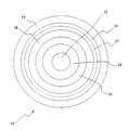
도 1은 본 발명의 실시예를 구성하는 광전송 파이버의 단면도,1 is a cross-sectional view of an optical transmission fiber constituting an embodiment of the present invention;
도 2는 본 발명의 다른 한 실시예를 구성하는 관 전송 파이버이 단면도.2 is a cross-sectional view of a tube transmission fiber constituting another embodiment of the present invention.
도 3은 본 발명에 따른 파이버의 예시적인 굴절율 프로파일을 나타낸 그래프.3 is a graph showing an exemplary refractive index profile of a fiber according to the present invention.
도 4는 본 발명에 따른 파이버의 또하나의 다른 예시적인 굴절율 프로파일을 나타낸 그래프.4 is a graph showing another exemplary refractive index profile of a fiber according to the present invention.
도 5는 본 발명에 따른 파이버의 또하나의 다른 예시적인 굴절율 프로파일을 나타낸 그래프.5 is a graph showing another exemplary refractive index profile of a fiber according to the present invention.
도 6은 본 발명의 파이버의 두 실시예에 대한 전송파장의 함수로써 색 분산 값을 나타내고, 또한 본 발명에 따른 파이버의 전송파장의 함수로서 감쇠값을 나타내는 그래프.Fig. 6 is a graph showing the color dispersion value as a function of the transmission wavelength for two embodiments of the fiber of the invention, and also showing the attenuation value as a function of the transmission wavelength of the fiber according to the invention.
도 7은 본 발명에 따른 파이버의 제1예를 나타낸 그래프.7 is a graph showing a first example of a fiber according to the present invention;
도 8은 본 발명에 따른 파이버의 제2예를 나타낸 그래프.8 is a graph showing a second example of the fiber according to the present invention;
도 9는 본 발명에 따른 파이버의 제3예를 나타낸 그래프.9 is a graph showing a third example of the fiber according to the present invention;
도 10은 본 발명에 따른 파이버의 제 4예를 나타낸 그래프.10 is a graph showing a fourth example of the fiber according to the present invention;
도 11은 본 발명에 따른 파이버의 제5예를 나타낸 그래프.11 is a graph showing a fifth example of a fiber according to the present invention;
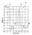
도 12는 도5의 종래기술에 따른 굴절율 프로파일을 가지는 파이버 셋트에 대하여 분산 기울기와 저하된 프로파일 사이의 관계를 나타낸 그래프.FIG. 12 is a graph showing the relationship between dispersion slope and degraded profile for a fiber set having a refractive index profile according to the prior art of FIG.
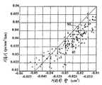
도 13은 본 발명에 따른 굴절율 프로파일을 가지는 파이버 셋트에 대한 분산기울기와 저하된 프로파일 사이의 관계를 나타낸 그래프.FIG. 13 is a graph showing the relationship between dispersion slope and degraded profile for a fiber set having a refractive index profile according to the present invention. FIG.
도 14는 MCVD 방법에 의해 출원이 만든 파이버 예비형성품의 굴절율 프로파일을 나타낸 것이다.Figure 14 shows the refractive index profile of the fiber preform made by the MCVD method.
첨부도면에 도시되어 있는 본 발명의 바람직한 실시예에 대하여 상세히 설명한다. 가능하다면 동일인용부호가 동일 유사한 부분에 대하여 전도면에 걸쳐 사용된다.Preferred embodiments of the present invention shown in the accompanying drawings will be described in detail. Wherever possible, the same quotation marks are used across the conducting surfaces for the same and similar parts.
본 발명을 구성하는 광파이버는 실질적으로 0의 굴절율차를 가지는 영역에 인접하는 저하된 굴절율 차의 영역을 포함하는 굴절율 프로파일(Profile)을 가지고 있다. 본 출원인은 이와같은 특성의 굴절율을 가지는 광 전송 파이버가1450nm와 1650nm 사이의 동작 파장범위에서 가장 낮은 동작 파장에서의 적정 분산값, 저분산 기울기 및 저감쇠를 포함하는 광전송 특성을 생성할 수 있음을 찾아내었다.An optical fiber constituting the present invention has a refractive index profile including a region of a reduced refractive index difference adjacent to a region having a refractive index difference of substantially zero. Applicants have shown that optical transmission fibers having such refractive indices can produce optical transmission characteristics including appropriate dispersion, low dispersion slope and attenuation at the lowest operating wavelength in the operating wavelength range between 1450 nm and 1650 nm. Found.
또한 본 출원인은 이와같은 굴절율 프로파일을 가지는 광전송 파이버는 1450nm와 1650nm 사이의 동작파장 트랜스미션 윈도(Transmission window)에 걸쳐 파장 분할 다중화(WDM)와 초-조밀 파장분할 다중화(HDWDM) 광전송을 효율적으로 지원할 수 있음을 찾아내었다.Applicants also note that optical transmission fibers with such refractive index profiles can efficiently support wavelength division multiplexing (WDM) and ultra-dense wavelength division multiplexing (HDWDM) optical transmission over an operating wavelength transmission window between 1450 nm and 1650 nm. I found out.
도 5에 도시된 바와같이 저하된 굴절율의 환형영역을 가지는 종래의 광파이버는 제 1 굴절율차 Δn1을 가지는 내부코어(52)를 포함한다.As shown in FIG. 5, a conventional optical fiber having an annular region of reduced refractive index includes an
제 1그래스(glass)층(54)은 환형영역의 내부코어(52)를 둘러싸며 저하된 굴절율차 Δn2를 가지고 있다.The
제 2그래스는 제 1그래스층을 둘러싸며 내부코어(52)내의 피크굴절율 보다는 작고 제로보다는 큰 그의 폭내에서 피크 굴절율차 Δn3을 가지고 있다.The second grass surrounds the first grass layer and has a peak refractive index difference Δn3 within its width that is less than the peak refractive index in the
클래드층(58)은 제 2그래스층을 둘러싸며 실질적으로 제로인 굴절율차를 가지고 있다. 또 다른 실시예에서 부(-)의 굴절율차를 가지는 외측 그래스층(59)은 점선으로 표시된 바와같이 제 2그래스층(56)의 외측에 배열되어 있다. 외측 그래스층(59)은 직접 제 2그래스층(56)을 둘러쌀 수도 있다.The
도 5의 프로타일은 환형층(54)을 가로질러 뻗어있는 저하량에 의하여 특성화 될 수 있다. r1이 내부코어(52)의 외측반경이고 r3이 제 2그래스층(56)의 내측반경이라면 파이버의 저하된 프로파일량은 다음 수학식 (1)으로 주어진다.The protile of FIG. 5 can be characterized by the amount of degradation extending across the

본 출원인은 본 발명에 따른 굴절율 프로파일을 가지는 광전송 파이버가 도 5의 파이버와 같은 종래의 파이버보다 약 1450nm에서 1650nm까지의 범위의 WDM 전송으로 사용하는데 보다 더 접합함을 찾아내었다.Applicant has found that the optical transmission fiber having the refractive index profile according to the present invention is more bonded for use with WDM transmission in the range of about 1450 nm to 1650 nm than conventional fibers such as the fiber of FIG. 5.
특히, 본 출원인은 환형 저하의 단면 외측부에, 저하된 굴절율차 보다도 절대값에 있어서 실질적으로 작은 굴절율차를 가지는 제 2 그래스층을 포함시킴으로서, 상기 수학식 1에 따른 파이버의 저하된 프로 파일양은 종래 파이버와 비교할 때 감소되는 반면에, 바람직하게 저분산 기울기는 트랜스미션 윈도에 걸쳐 달성될 수 있음을 찾아내었다. 더 낮은 저하된 프로파일양은 부(-)의 도판트가 더욱더 낮은량으로 되게하고 이것에 의해 파이버 제조 및 저감쇠를 용이하게 한다. 또한 파이버는 트랜스미션 윈도의 저부단부에서 적정의 분산값을 가진다.In particular, the Applicant includes a second grass layer having a refractive index difference substantially smaller in absolute value than the reduced refractive index difference on the outer side of the cross section of the annular deterioration, so that the amount of the degraded profile of the fiber according to
본 발명의 바람직한 실시예에 따른 광파이버는 도 1에 개략적으로 도시되어 있으며, 전체적으로는 인용부호 10으로 표시되어 있다. 본 발명에 따라 WDM에서 사용하기 위한 광전송 파이버는 제 1 굴절율차 Δn1을 가지는 내부코어와, 상기 파이버의 길이에 따라 내부코어를 방사상으로 둘러싸고 제로보다는 작은 제 2 굴절율 차 Δn2를 가지는 제 1층과, 상기 파이버의 길이에 따라 방사상으로 제 1층을 둘러싸고 실질적으로 제로인 제 3 굴절율차 Δn3을 가지는 제 2층과, 상기 파이버의 길이에 따라 방사상으로 제 2층을 둘러싸고 제로보다는 큰 제 4 굴절율차 Δn4를 가지는 제 3층을 포함한다.An optical fiber according to a preferred embodiment of the present invention is schematically illustrated in FIG. 1, and is indicated generally by the
클래드층은 그래스 코어를 둘러싸며 실질적으로 제로와 같은 굴절율차를 가진다.The cladding layer surrounds the grass core and has a substantially zero refractive index difference.
바람직하기로는 상기 그래스 코어는 파이버의 길이에 따라 방사상으로 제 3층을 둘러싸며 제로보다는 작은 제 5 굴절율차 Δn5를 가지는 제 4층을 구비한다.Preferably the grass core has a fourth layer radially surrounding the third layer along the length of the fiber and having a fifth refractive index difference Δn5 , which is less than zero.
광파이버는 캐리어 파장범위에 걸쳐서 적어도 1.5ps/nm/km의 분산값(바람직하기로는 조밀 WDM 전송에 대하여서는 2.5ps/nm/km이상)과 캐리어 파장범위에 걸쳐서 0.07ps/nm2/km 보다 작은(바람직하기로는 약 0.05ps/nm2/km보다 작은)분산 기울기를 가진다.The optical fiber has a dispersion value of at least 1.5 ps / nm / km over the carrier wavelength range (preferably over 2.5 ps / nm / km for dense WDM transmission) and less than 0.07 ps / nm2 / km over the carrier wavelength range. It has a scattering slope (preferably less than about 0.05 ps / nm2 / km).
도 1에 개략적으로 도시된 바와같이(스케일에 도시되지 않음) 광파이버(10)는 복수의 광전도 그래스층을 포함한다. 파이버(10)의 축 중심은 도포된 그래스로 만들어진 내부코어(12)이다. 내부코어(12)는 제 1굴절율차 Δn1과 반경 r1을 가진다. 굴절율차란 주어진 그래스층과 클래드층간의 굴절율에 있어서 차를 말한다. 즉, 예를들어 내부코어(12)의 굴절율차 Δn1은 n1-n 클래드와 같으며 Δn1은 0.004~0.010 범위내에서 선택될 수 있고, 한편, r1은 2~5㎛ 범위내에서 선택될 수 있고 한편, Δn1과 r1에 대한 바람직한 범위는 각각 0.005~0.008과 3~4㎛이다. 바람직하기로는 내부코어(12)는 GeO2와 같이 순수한 SiO2의 굴절율을 증가시키는 물질로 도포된 SiO2로 만들어진다.As schematically shown in FIG. 1 (not shown in scale), the
제 1 그래스층(14)은 파이버(10)의 길이에 따라 방사상으로 내부코어(12)를 둘러싼다. 제 1 그래스층은 폭에 걸쳐 저하된 굴절율 Δn2를 가진다. 본 발명의 기술분야에서 공지된 바와같이, 굴절율의 저하는 주어진 그래스층의 굴절율이 클래드층의 굴절율보다 적으며, 예를들어 상기 수학식 (1)에서 주어진 바와같이, Δn2는 0보다 작다. 본 발명의 기술분야에서 공지된 바와같이, 파이버의 분산 기울기는 일반적으로 저하된 굴절율의 영역을 가지는 그래스층을 포함함으로써 감소될 수 있고, Δn2는 -0.006~0.001내에서 선택될 수 있고 한편 Δn2에 대한 바람직한 범위는 -0.003에서 -0.002까지이다. 바람직하기로는 제 1그래스층(14)은 순수한 SiO2로 만들어진다. 제 1그래스층(14)의 폭은 1~6㎛ 범위내에서 선택될 수 있고, 바람직한 범위는 2~4㎛이다.The
제 2그래스층(16)은 파이버(10)의 길이에 따라 방사상으로 제 1 그래스층(14)을 둘러싼다. 제 2 그래스층(16)은 제 1 그래스층의 외부반경 r2에서 반경 r3까지 연장되어 있고 그의 폭내에 Δn3의 굴절율을 가진다. 제 2 그래스층(16)의 굴절율 Δn3은 절대값으로 Δn2의 약 40%보다 작고, 바람직하기로는 Δn2의 약 20%보다 작다. 바람직하기로는, 제 2그래스층은 후술하는 바와같이, 클래드층의 굴절율과 실질적으로 같은 굴절율을 가지는 임의 물질이나 물질의 결함으로 만들어 질 수 있지만, 제 2 그래스층은 SiO2로 만들어진다. 제 2그래스층(16)의 폭은 1~5㎛ 범위내에서 선택될 수 있으며 바람직한 범위는 2~4㎛이다.The
제 3그래스층(18)은 파이버(10)의 길이에 따라 제 2 그래스층(16)을 방사상으로 둘러싼다. 제 3 그래스층은 제 2 그래스층(16)간의 외측반경 r3으로부터 외측반경 r4까지 연장되어 있다. 제 3그래스층은 최대 굴절율차 Δn4를 가진다. Δn4는 0.003~0.010의 범위내에서 선택될 수 있고, 바람직한 범위는 0.004~0.008이다. 제 3그래스층(18)의 폭은 1~4㎛ 범위내에서 선택될 수 있고, 바람직한 범위는 2~3㎛이다.The
제 4그래스층(15)은 파이버(10)의 길이에 따라 제 3 그래스층(18)을 방사상으로 둘러싼다. 제 4그래스층은 제 3 그래스층(18)의 외측반경 r4로부터 외측반경 r5까지 연장되어 있다. 제 4그래스층(18)은 제로보다 작은 굴절율차 Δn5를 가진다. Δn5는 -0.003에서 0.0까지의 범위내에서 선택될 수 있고, 바람직한 범위는 3~5㎛이다.The
최종적으로 광도전 클래드층(19)은 종래 방법에서 제 3 그래스층(18)을 둘러싸며 파이버(10)의 축에따라 전파하는 광을 유도하는데 도와준다. 클래드층(19)은 실질적으로 제로와 같은 굴절율차를 가진 순수한 SiO2 그래스를 구비하거나 또는 굴절율을 변경하는 도판트를 포함한다.Finally, the
점선으로 표시된 또 하나의 다른 실시예에서, 실질적으로 제로인 굴절율차 Δn6을 가지는 제 5 그래스층(17)은 제 3그래스층(18)과 제 4그래스층(15) 사이에 구비되어 있다.In another embodiment, indicated by the dotted line, a
도 2에 도시된 바와같은 구체적인 실시예는 제 4 및 제 5 그래스층이 없도록 클래드층(19)이 제 3 그래스층(18)을 둘러쌀 때 도 1의 실시예로 이끌어 낼 수 있다. 그러나, 제 5 그래스층(17)을 가지거나 또는 가지지 않고 외측 저하된 그래스층(15)을 가지는 도 1의 실시예가 바람직하며, 그 이유는 그들이 동작 파장에서 싱글모드의 달성을 단순하게 할 수 있기 때문이다.The specific embodiment as shown in FIG. 2 can lead to the embodiment of FIG. 1 when the
도 3은 본 발명의 제 1 실시예에 대한 파이버(10)의 반경에 걸친 굴절율 프로파일(20)을 나타낸 것으로, 여기서 축(32)은 파이버(10)의 축중심을 나타내며 축(34)은 실질적으로 제로의 굴절율차를 표시한다. 도시된 바와같이, 굴절율 프로파일은 저하된 굴절율을 가지는 제 1층(24)과 그 다음 실질적으로 제로의 굴절차를 가지는 제 2층(20)을 가진다. 층(24,26)은 내부코어층(22)과 외측피크부(28) 사이에 저하된 트랜치(Trench)가 제공된다. 바람직한 한 실시예에서, 외측 피크부(28)의 굴절율차 Δn4는 내부코어(22)의 굴절율차 Δn1보다 작다. 또 다른 실시예에서는 인용부호 23에 의해 도시된 바와같이, 외측 피크부(28)의 굴절율차 Δn4보다 더 클 수도 있다. 도시된 바와같이 저하된 굴절율차를 가지는 외층(29)은 외측 피크 부(28)의 외측에 놓여지며, 외층(29)은 외측 피크부(28)를 둘러싸거나 또 다른 실시예에서는 실질적으로 제로의 굴절율차를 가지는 중간층(27)이 외측 피크부(28)와 외층(29) 사이에 배열될 수 있다.3 shows a
도 4는 도 2의 실시예에 상응하는 또 하나의 다른 굴절율 프로파일을 나타낸 것이며, 여기서 클래드층(30)은 직접 외측 피크부(28)를 둘러싸고 있다. 도 4의 굴절율 프로파일은 외층(29)과 중간층(27)이 없다는 점에서 도 3의 굴절율 프로파일과 다르다.FIG. 4 shows another alternative refractive index profile corresponding to the embodiment of FIG. 2, where the clad
도 6은 본 발명에 따른 굴절율 프로파일을 가지는 파이버(10)의 예시적인 분산곡선(40,42)과 감쇠곡선(44)을 나타낸 것이다. 곡선(44)에 도시된 바와같이, 파이버(10)의 감쇠는 1450~1650nm의 트랜스미션 윈도보다 작은 파장에서 피크(46)에 도달한다. 파이버(10)의 감쇠는 약 1450nm에서 1650nm까지의 트랜스미션 윈도에 걸쳐 약 0.27dB/km보다 작다.6 shows exemplary dispersion curves 40 and 42 and attenuation curves 44 of a
역시 곡선(40)으로 도시된 바와같이, 제 1 실시예에 따른 파이버(10)의 1450nm에서의 분산은 약 ps/nm/km이다. 분산곡선의 기울기는 1450nm에서 1650nm의 밴드폭에 걸쳐 0.06ps/nm2/km보다 작다. 파이버(10)는 1650nm에서 약 12ps/nm/km보다 작은 분산값을 가진다. 곡선(42)은 본 발명의 제 2 실시예를 나타낸 것이다. 여기서 제로-분산(Zero-dispersion)파장은 1480nm 근방에서 발생한다. 제 2 실시예에 따른 파이버(10)는 1650nm에서 약 9ps/nm/km보다 작은 분산값을 가진다.As also shown by
또한 1550nm에서 파이버(10)의 유효영역은 약 50㎛2보다 더 크다. 본 발명 의 기술분야에서 공지된 바와같이, 큰 유효영역은 비선형 효과의 영향을 제한하는데 도움을 준다. 그러나 파이버의 유효영역의 증가에 따라 파이버의 분산 기울기가 증가한다. 본 발명의 파이버는 비선형 효과의 영향을 제한하는데 충분한 크기인 유효영역을 가지면서도 유효영역과 분산 기울기 사이의 최적 수지 균형점을 달성하는데 충분히 작다.Also, the effective area of the
본 발명에 따른 굴절율 프로파일을 가지는 파이버(10)의 제 1 실시예의 전송특성은 표 1에 나타난 바와같다.The transmission characteristics of the first embodiment of the
도 7-9는 본 발명의 제 1 실시예에 따른 굴절율 프로파일을 가지는 파이버의 특정예를 나타낸 것이다.7-9 illustrate specific examples of fibers having a refractive index profile according to the first embodiment of the present invention.
예 1.Example 1.
도 7에 도시된 바와같이, 내부코어(72)는 약 0.0063의 실질적으로 일정한 굴절율차를 가지며, 약 3.3㎛의 반경 r1에 대하여 연장되어 있다.As shown in FIG. 7, the
내부코어(72)의 굴절율차는 내부코어의 길이를 GeO2나 또는 임의의 다른 공지의 굴절율 증가 도판트로 도핑함으로써 증가될 수 있다. 도 7은 예리한 단부를 가지는 내부코어(72)를 도시하고 있지만, 그 프로파일은 실질적인 구현에 있어서 둥글어도 된다.The refractive index difference of the
제 1그래스층(74)은 약 -0.0010의 저하된 굴절율차 Δn2를 가지며 약 2.8㎛의 방사상 거리로 연장되어 있다. 저하된 프로파일량은 약 -0.013㎛2이다. 제 1 그래스층(74)의 굴절율차는 제 1 코어층의 폭을 불소 또는 임의의 다른 공지의 굴절율 감소 도판트로 도핑함으로서 감소되게 할 수 있다. 제 2 그래스층(76)은 약 제로의 굴절율차 Δn3을 가지며 약 2.0㎛의 방사상 거리로 연장되어 있다.The
제 3 그래스층(78)은 포물선의 프로파일을 가지며 약 2.9㎛ 폭내의 중앙점에서 약 0.0032의 최대 굴절율차 Δn4에 도달한다. 제 3 그래스층의 굴절율차는 그래스층을 증가하는량의 GeO2나 또는 다른 공지의 굴절율 증가 도판트로 도핑함으로써 형성될 수 있다.The
제 3 그래스층(78)은 약 0의 굴절율차를 가지는 클래드층(80)에 의하여 둘러싸여 있다.The
도 7에 도시된 파이버(10)의 특정 실시예는 다음의 광학전송 특성을 가지며, 이들 특성은 컴퓨터 시뮬레이션을 통하여 발생된 것이다.A particular embodiment of the
케이블 컷오프 ≤1400nmCable cutoff ≤1400nm
1450nm에서 분산 = 1.9ps/nm/kmDispersion at 1450 nm = 1.9 ps / nm / km
1450nm에서 분산기울기 = 0.050ps/nm2/kmDispersion slope at 1450 nm = 0.050 ps / nm2 / km
1550nm에서 분산 = 6.5ps/nm/kmDispersion at 1550 nm = 6.5 ps / nm / km
1550nm에서 분산기울기 = 0.046ps/nm2/kmDispersion slope at 1550 nm = 0.046 ps / nm2 / km
1550nm에서 모드 필드 다이아미터 = 9.1㎛Mode Field Diameter at 1550 nm = 9.1 μm
1550nm에서 유효영역 = 63㎛2Effective area at 1550 nm = 63 μm2
비선형계수 gamma = 1.4w-1km-1Nonlinear coefficient gamma = 1.4w-1 km-1
마크로 벤딩(Macro Bending)감쇠 = <0.5dB, 60mm직경 맨드렐(Mandrel)상에서 100턴에 대하여,Macro Bending Attenuation = <0.5 dB, for 100 turns on a 60 mm diameter Mandrel,
마크로 벤딩 감도 = 2.9(dB/Km/g/mm), 팽창 가능한 보빈 방법에 의해 결정, 이 방법은 G.Grasson와 F. Meli의 ECOC 88페이지 526-ff, "Microbending losses of cabled single-mode fibers"나 또는 G.Grasso. 등의 International Wire and Cable Symposium 1988페이지 722-ff, "Microbending effects in single-mode optical cables"의 예제에 설명되어 있는 방법.Macro bending sensitivity = 2.9 (dB / Km / g / mm), determined by the inflatable bobbin method, which is described by G. Grasra and F. Meli's ECOC on page 88 526-ff, "Microbending losses of cabled single-mode fibers. "I or G.Grasso. International Wire and Cable Symposium et al. 1988, page 722-ff, "Microbending effects in single-mode optical cables."
예 2Example 2
도 8에 도시된 바의 또 하나의 다른 실시예에서, 내부코어(72)는 약 0.0067의 실질적으로 일정 굴절율차 Δn1을 가지며, 약 3.2㎛의 직경 r1에 대하여 연장되어 있다. 내부코어(72)의 굴절율차는 내부코어의 폭을 GeO2나 또는 다른 임의의 공지된 굴절율 증가 도판트로 도핑함으로서 증가될 수 있다.In another embodiment as shown in FIG. 8, the
제 1 그래스층(74)은 약 -0.0015의 저하된 굴절율차 Δn2를 가지며 약 3.4㎛ 의 방사상 거리로 연장되어 있다. 저하된 프로파일량은 약 -0.025㎛2이다. 제 1 그래스층(74)의 굴절율차는 제 1 코어층의 폭을 불소나 또는 다른 임의의 공지된 굴절율 감소 도판트로 도핑함으로써 감소될 수 있다. 제 2 그래스층(76)은 약 제로의 굴절율차를 가지며 약 2.2㎛의 방사상 거리로 연장되어 있다.The
제 3 그래스층(78)은 실질적으로 포물선 프로파일을 가지며 약 1.1㎛폭내의 중간점에서 약 0.0090의 최대 굴절율차에 이른다. 제 3 그래스층의 굴절율차는 그래스층을 증가하는 량의 GeO2나 또는 다른 임의의 공지된 굴절율 증가 도판트를 사용하여 도핑함으로서 형성될 수 있다.The
도시된 바와같이, 도 8의 실시예는 내부피크(72)보다도 더 높은 굴절율차를 가지는 외부 피크(78)를 가진다. 제 3 그래스층(78)은 약 제로의 굴절율차를 가지는 클래드층(80)에 의해 둘러싸여 있다.As shown, the embodiment of FIG. 8 has an
도 8에 도시된 파이버(8)의 특정 실시예는 다음과 같은 광 전송 특성을 가진다.A particular embodiment of the
케이블 컷오프 ≤ 1400nmCable cutoff ≤ 1400nm
1450nm에서 분산 = 1.6ps/nm/kmDispersion at 1450 nm = 1.6 ps / nm / km
1450nm에서 분산 기울기 = 0.042 ps/nm2/kmDispersion slope at 1450 nm = 0.042 ps / nm2 / km
1550nm에서 분산 = 5.0ps/nm/kmDispersion at 1550 nm = 5.0 ps / nm / km
1550nm에서 분산 기울기 = 0.036 ps/nm2/kmDispersion slope at 1550 nm = 0.036 ps / nm2 / km
1550nm에서 모드 필드 다이아미터 = 8.6㎛Mode Field Diameter at 1550 nm = 8.6 μm
1550nm에서 유효영역 = 57㎛2Effective area at 1550 nm = 57 μm2
비선형 계수 gamma = 1.6w-1km-1Nonlinear coefficient gamma = 1.6w-1 km-1
마크로 벤딩 감쇠 < 0.5dB, 60m 직경맨드렐상의 100턴에 대하여,For macro bending attenuation <0.5 dB, for 100 turns on a 60 m diameter mandrel,
마크로 벤딩 감도 = 2.1(dB/km)/(g/mm), 확장 가능한 보빈 방법에 의해 결정Macro bending sensitivity = 2.1 (dB / km) / (g / mm), determined by scalable bobbin method
예 3Example 3
도 9에 도시된 다른 또 하나의 실시예에서, 파이버(10)의 내부코어(72)는 약 0.0067의 실질적인 일정 굴절율차Δn1을 가지며, 약 3.15㎛의 반경 r1로 연장되어 있다. 내부코어(72)의 굴절율차는 내부코어의 폭을 GeO2나 또는 임의의 다른 공지된 굴절율 증가 도판트로 도핑함으로써 증가 될 수 있다.In yet another embodiment shown in FIG. 9, the
제 1 그래스층(74)은 약 -0.0014의 저하된 굴절율차를 가지며 약 3.1㎛의 방사상 거리로 연장되어 있다. 저하된 프로파일량은 약 -0.021㎛2이다. 제 1 그래스층(74)의 굴절율차는 제 1 코어층의 폭을 불소나 또는 다른 임의의 공지된 굴절율 감소 도판트로 도핑함으로써 감소될 수 있다. 제 2 그래스층(76)은 약 제로의 굴절율차를 가지며 약 3.0㎛의 방사상 거리로 연장되어 있다.The
제 3 그래스층(78)은 실질적으로 포물선 프로파일을 가지며 약 3.2㎛폭내의 중간점에서 약 0.0040의 최대 굴절율차 Δn4에 이른다. 제 3 그래스층의 굴절율차는 그래스층을 증가하는 량의 GeO2나 또는 다른 임의의 공지된 굴절율 증가 도판트 로 도핑함으로써 형성될 수 있다.The
제 3 그래스층(78)은 4.0㎛의 파이버 폭에 따라 약 -0.0011의 굴절율 차이를 가지는 제 4 그래스층(79)에 의하여 둘러싸여 있다.The
제 4 그래스층(79)은 약 0의 굴절율차를 가지는 클래드층(80)에 의하여 둘러싸여 있다.The
도 9에 도시된 파이버(10)의 특정 실시예는 다음의 광전송 특성을 가진다.A particular embodiment of the
케이블 컷오프 ≤ 1400nmCable cutoff ≤ 1400nm
1450nm에서 분산 = 1.6ps/nm/kmDispersion at 1450 nm = 1.6 ps / nm / km
1450nm에서 분산 기울기 = 0.038ps/nm2/kmDispersion slope at 1450 nm = 0.038 ps / nm2 / km
1550nm에서 분산 = 5.1ps/nm/kmDispersion at 1550 nm = 5.1 ps / nm / km
1550nm에서 분산 기울기 = 0.034ps/nm2/kmDispersion slope at 1550 nm = 0.034 ps / nm2 / km
1550nm에서 모드 필드 다이아미터 = 8.6㎛Mode Field Diameter at 1550 nm = 8.6 μm
1550nm에서 유효영역 = 56㎛2Effective area at 1550 nm = 56 μm2
비선형 계수 gamma = 1.6w-1km-1Nonlinear coefficient gamma = 1.6w-1 km-1
마크로벤딩 감쇠 < 0.5dB, 60m 직경, 맨드렐상의 100턴에 대하여,Macro bending attenuation <0.5 dB, 60 m diameter, for 100 turns on mandrel,
마크로벤딩 감도 = 2.0(dB/km)/(g/mm), 확장 가능한 보빈 방법에 의해 결정Macro bending sensitivity = 2.0 (dB / km) / (g / mm), determined by scalable bobbin method
본 발명에 따라, 본 실시예에서 설명되는 바의 굴절율 프로파일을 가지는 광전송 파이버는 보다 큰 파장에서 동작하는 WDM 전송 시스템으로 사용될 수 있다. 구체적으로는 본 발명의 제 2 실시예는 약 1530nm에서 1650nm 범위의 캐리어 파장을 가지는 WDM 전송 시스템으로 사용될 수 있다. 도 4는 제 2 실시예에 따른 파이버에 대한 분산 곡선(42)을 나타낸 것이다.According to the present invention, an optical transmission fiber having a refractive index profile as described in this embodiment can be used as a WDM transmission system operating at a larger wavelength. Specifically, the second embodiment of the present invention may be used as a WDM transmission system having a carrier wavelength in the range of about 1530 nm to 1650 nm. 4 shows a
도 4에 도시된 바와같이, 파이버(10)의 제로-분산 파장은 1480nm 근방으로 시프트 되어 있다. 분산곡선(42)의 분산 기울기는 바람직하게는 약 0.06ps/nm2/km보다 작다. 이것에 의해 보다 큰 파장에 걸쳐서의 분산값은 감소된다. 바람직하기로는 파이버(10)는 1650nm의 더 큰 파장에서 약 9ps/nm/km보다 작은 분산값을 가진다.As shown in FIG. 4, the zero-dispersion wavelength of the
제 2 실시예의 파이버에 대한 광전송 특성은 표 2로 주어진다.The optical transmission characteristics for the fiber of the second embodiment are given in Table 2.
도 10~11은 본 발명의 제 2 실시예에 따른 굴절율 프로파일을 가지는 파이버의 특정예를 나타낸 것이다.10 to 11 show specific examples of fibers having a refractive index profile according to a second embodiment of the present invention.
예 4Example 4
도 10은 제 2 실시예에 따른 파이버의 굴절율 프로파일을 나타낸 것이다.10 shows a refractive index profile of a fiber according to a second embodiment.
파이버(10)의 내부코어(72)는 약 0.006의 실질적으로 일정한 굴절율차를 가 지고 있으며 약 3.2㎛의 반경 r1으로 연장되어 있다. 내부코어(72)의 굴절율차는 내부코어의 폭을 GeO2 나 또는 다른 공지된 굴절율 증가 도판트로 도핑함으로써 증가될수 있다.The
제 1 그래스층(74)은 약 -0.0013의 저하된 굴절율 차 Δn2를 가지고 있으며 약 3.3㎛의 방사상 거리에 대하여 연장되어 있다. 저하된 프로파일량은 약 -0.021㎛2이다. 제 1 그래스층(74)의 굴절율차는 제 1 그래스층의 폭을 불소나 또는 임의의 다른 공지된 굴절율 감소 도파트를 도핑함으로써 감소될 수 있다. 제 2 그래스층(76)은 약 제로의 굴절율차를 가지며 약 2.4㎛의 방사상 거리에 대하여 연장되어 있다.The
제 3 드래스층(78)은 실질적으로 포물선 프로파일이며 약 2.1㎛의 폭내에서의 중간점에서 약 0.0058의 최대굴절율차 ㅿn4에 이른다. 제 3 그래스층의 굴절율차는 그래스층을 증가하는 량의 GeO2나 또는 다른 임의의 공지된 굴절율 증가 도판트로 도핑함으로써 형성될 수 있다.The
제 3 드래스층(78)은 4.3㎛ 폭에 따라 약 -0.0008의 굴절율차를 가지는 제 4 그래스층(79)에 의해 둘러 싸여 있다.The
제 4 드래스층(79)은 약 제로의 굴절율차를 가지는 클래도층(80)에 의하여 둘러 싸여 있다.The
도 10에 도시되어 있는 파이버(10)의 특정 실시예는 다음과 같은 광전송 특 성을 가진다.A specific embodiment of the
케이블 컷오프 ≤1500㎚Cable cutoff ≤1500nm
1550㎚에서 분산 =3.3 ㎰/㎚/㎞Dispersion at 1550 nm = 3.3 μs / nm / km
1550㎚에서 분산기울기 = 0.038 ㎰/㎚2/㎞Dispersion slope at 1550 nm = 0.038 ㎰ / nm2 / km
1550㎚에서 모드필드 다이어미터 = 8.7 ㎛Modefield Diameter at 1550 nm = 8.7 μm
1550㎚에서 유효영역 = 59 ㎛2Effective area at 1550 nm = 59 μm2
비선형계수 gamma =1.5W-1km-1Nonlinear coefficient gamma = 1.5W-1 km-1
마크로벤딩 감쇠 〈 0.5㏈, 60mm 직경 맨드렐상에서 100턴에 대하여,Macro bending attenuation <0.5 ms, for 100 turns on a 60 mm diameter mandrel,
마이크로벤딩 감도 = 3.0 (㏈/km)/(g/m), 확장가능한 보빈방법에 의한 결정.Micro bending sensitivity = 3.0 (㏈ / km) / (g / m), determined by scalable bobbin method.
예 5Example 5
도 11은 제 2 실시예에 따른 파이버의 또 다른 하나의 굴절율 프로파일을 나타낸 것이다. 파이버(10)의 내부코어(72)는 α=4 인 α- 프로파일 형상을 가지며 약 0.0070의 최대굴절율차를 가진다. 내부코어(72)는 약 3.7㎛의 반경 r1에 대하여 연장되어 있다.11 shows another refractive index profile of the fiber according to the second embodiment. The
내부코어(72)의 굴절율차는 내부코어의 폭을 GeO2나 또는 임의의 다른 공지된 굴절율 증가 도판트로 도핑함으로써 증가될 수 있다.The refractive index difference of the
제 1 그래스층(74)은 실질적으로 포물선의 저하된 프로파일을 가지며 약 2.4㎛ 폭내의 중간점에서 약 -0.0024의 최소굴절율 차 Δn2로 된다.The
제 1 그래스층(74)의 굴절율차는 제 1 그래스층의 폭을 불소나 또는 임의의 다른 공지된 굴절율 감소 도판트로 도핑함으로써 감소되게 할 수 있다. 제 2 그래스층(76)은 약 제로의 굴절율차 Δn3을 가지며 약 2.6㎛의 방사상거리에 대하여 연장되어 있다.The refractive index difference of the
제 3 그래스층(78)은 실질적으로 포물선 프로파일을 가지며 약 2.1㎛의 폭내의 중간점에서 약 0.0063의 최대 굴절율차 Δn4로 된다.The
제 3 그래스층의 굴절율차는 제 3 그래스층을 증가하는 량의 GeO2 나 또는 임의의 다른 공지된 굴절율 증가 도판트로 도핑함으로써 형성될수 있다.The refractive index difference of the third grass layer may be formed by doping the third grass layer with an increasing amount of GeO2 or any other known refractive index increasing dopant.
제 3 그래스층(78)은 2.9㎛ 폭에 걸쳐 약 -0.001의 최소 굴절율차를 가지는 저하된 제 4 그래스층(79)에 의하여 둘러 싸여 있다.The
제 4 그래스층(79)은 약 제로의 굴절율차를 가지는 클래드층(80)에 의해 둘러싸여 있다.The
도 11에 도시된 파이버(10)의 특정 실시예는 다음과 같은 광 전송특성을 가진다.A particular embodiment of the
케이블 컷오프 ≤ 1500㎚ Cable cutoff ≤ 1500nm
1550㎚에서 분산 = 3.5 ps/nm/km Dispersion at 1550 nm = 3.5 ps / nm / km
1550㎚에서 분산기울기 = 0.043ps/nm2/kmDispersion slope at 1550 nm = 0.043 ps / nm2 / km
1550㎚에서 모드필드다이어미터 = 8.9㎛ Mode field meter at 1550 nm = 8.9 μm
1550㎚에서 유효영역 = 61㎛2Effective area at 1550 nm = 61 μm2
비선형계수 gamma=1.4w-1 kw-1Nonlinear Coefficient gamma = 1.4w-1 kw-1
마크로벤딩 감쇠 〈 2.5 dB, 60mm 직경 맨드렐상에서 100턴에 대하여 Macro bending attenuation <2.5 dB, for 100 turns on a 60 mm diameter mandrel
마크로벤딩 감도 = 3.9(dB/km)/(g/mm), 확장가능한 보빈 방법에 의해 결정. Macro bending sensitivity = 3.9 (dB / km) / (g / mm), determined by scalable bobbin method.
도 12는 도 5의 종래 디자인에 따른 굴절율 프로파일을 가진 파이버 세트에 대한 분산기울기와 저하된 프로파일량 사이의 관계를 나타낸 것이다.FIG. 12 shows the relationship between the dispersion slope and the reduced profile amount for a fiber set having a refractive index profile according to the prior design of FIG. 5.
도 5에 따른 굴절율 프로파일을 정의하는 파리미터 값들은 랜덤하게 선정되었다. 각세트의 광전송 특성은 컴퓨터 시뮬레이션에 의해 평가되었다.Parameter values defining the refractive index profile according to FIG. 5 were randomly selected. The light transmission characteristics of each set were evaluated by computer simulation.
도 12에서의 각 십자형은 다음 범위내의 광전송특성을 얻는 굴절율에 상응하는 파리미터 값의 셋트를 나타낸 것이다.Each cross in Fig. 12 shows a set of parameter values corresponding to the refractive indices for obtaining optical transmission characteristics within the following ranges.
이론적 컷오프 〈 1800nmTheoretical Cutoff 〈1800nm
1550nm에서 분산 2-8 ps/nm/kmDispersion 2-8 ps / nm / km at 1550nm
유효영역 53-57 ㎛2Effective area 53-57 μm2
마크로벤딩 감쇠 〈 0.5 dB, 60mm 직경 맨드렐상에서 100턴에 대하여,Macro bending attenuation <0.5 dB, for 100 turns on a 60 mm diameter mandrel,
마이크로벤딩 감도 〈 5 (dB/km)/(g/mm), 확장가능한 보핀 테스트 방법에 의한 결정.Microbending Sensitivity <5 (dB / km) / (g / mm), determined by scalable Boffin test method.
한편 상기 범위 이외의 광전송특성을 가지는 굴절을 프로파일을 주는 파라미 터 셋트는 도 12에 도시되어 있지 아니하였다.On the other hand, a parameter set for profiling refractions having light transmission characteristics outside the above range is not shown in FIG.
도 4에 따른 본 발명의 굴절율 프로파일셋트에 대한 비교예가 도 13에 도시되어있다.A comparative example for the refractive index profile set of the present invention according to FIG. 4 is shown in FIG. 13.
선택기준은 상기 종래예와 동일하다.The selection criteria are the same as in the conventional example.
양자의 그래프에서 라인(90)은 수학식(2)에 나타낸, 분산기울기 S(ps/nm2/km의 단위)와 저하된 프로파일량 V(㎛2의 단위)사이의 관계식에 상응하게 도시되었다.
상기 실시예에 의하여 도시된 바와 같이, 저 분산 기울기와 저하된 프로파일량간의 타협점이 있다.As shown by this embodiment, there is a compromise between low dispersion slope and reduced profile amount.
해당 파이버 성능에 대하여, 분산 기울기가 낮으면 낮을수록 저하된 프로파일량은 높아지며 그래서 제조의 복잡성과 도판트 용량을 증가시킨다.For that fiber performance, the lower the dispersion slope, the higher the degraded profile amount, thus increasing the complexity of manufacturing and the dopant capacity.
그러나, 도 12와 도 13내의 상기 그래프는 도 5의 종래 기술에 해당하는 굴절율 프로파일은 수학식 2에 주어진것보다 분산기울기 값이 더 커지는 경향이 있으며, 반면에 본 발명에 따른 굴절율 프로파일은 수학식 2에 의하여 주어진것들 이하로 집중되는 분산기울기 값을 가지는 것을 나타내고 있다.However, the graphs in FIGS. 12 and 13 show that the refractive index profile corresponding to the prior art of FIG. This indicates that we have a scatter slope that is concentrated below those given by 2.
MCVD 기술로 본 출원인에 의해 만들어진 파이버 예비형성(preform)의 굴절율 프로파일이 도 14에 도시되어 있다. 상기 예비형성은 내부코어 영역(72), 제 1 그래스층(74), 제 2 그래스층(76), 제 3 그래스층(78), 저하된 제 4 그래스층(79) 및 클래스층(80)을 포함한다.The refractive index profile of the fiber preform made by the applicant with the MCVD technique is shown in FIG. 14. The preliminary formation may include an
상기 예비형성은 도 3을 참조하여 설명된 실시예에 따른 본 발명의 것들에 상응한다.The preforms correspond to those of the invention according to the embodiment described with reference to FIG. 3.
연신공정(drawing process)동안, 특히 도판트용융으로 인해 연신된 파이버의 굴절율 프로파일은 일반적으로 예비형성의 굴절율 프로파일로부터 약간의 변형을 입을수 있다. 특히 제 2 그래스층(70)은 연신공정동안 제 2 그래스층의 굴절율에서 해당하는 약간의 증가를 감안하여 연신되는 파이버의 소정 굴절율 값보다 더 작아지는 굴절율 차의 값을 얻도록 도프된다. 이와 같은 증가의 량은 예비형성 되는 특성이나 파이버 연신공정의 파리미터에 토대하여 당업자에 의하여 결정될 수 있다.During the drawing process, the refractive index profile of the drawn fiber, in particular due to dopant melting, can generally undergo some deformation from the refractive index profile of the preform. In particular, the
본 출원인은 도 3을 참조하여 일반적으로 설명한 것과 상응하는 굴절율 프로파일, 특히 제 2 그래스층(76)은 제 1 그래스층(74)의 굴절율차의 40%보다 절대치에서 작은 굴절율 차를 가지는 예비 형성이 1452~1650㎚의 파장범위에 걸쳐 소망의 광전송특성을 가지며 구체적으로는 1550㎚에서 약 0.21dB/kmdml 감쇠, 낮은 마크로벤딩 및 마이크로 벤딩 손실 및 분산기울기와 저하된 프로파일량간의 개선된 관계를 가지는 광파이버가 얻어지도록 종래의 연신공정에 의하여 연신 될 수 있음을 알았다.Applicants note that a refractive index profile corresponding to that generally described with reference to FIG. 3, in particular the
MCOD 기술이 도 14에 도시된 예비 형성품을 만들기 위해 사용될수 있지만, 다른 이용가능한 증감 적층기술이 동일목적으로 당업자에 의하여 선택될수 있다.Although MCOD techniques can be used to make the preforms shown in FIG. 14, other available sensitization stacking techniques can be selected by one skilled in the art for the same purpose.
본 발명의 파이버는 여러 가지 수정이나 변경이 본 발명의 범위를 일탈함이 없이 이루어질 수 있음이 본 발명에 속하는 기술 분야의 통상의 지식을 가진자에게 명해할 것이다.It will be appreciated by those skilled in the art that the fibers of the present invention may be variously modified or changed without departing from the scope of the present invention.
예를 들면, 각 도면에 도시된 굴절율 프로파일은 바람직한 실시예의 예시적 목적을 위한 것이다. 정밀한 형상, 방사상거리, 굴절율차가 앞에서 정의된 바와 같은 관련된 유효의 프로파일을 얻도록 본 발명 기술분야의 통상의 지식을 가진자에 의하여 변동될 수 있다.For example, the refractive index profile shown in each figure is for illustrative purposes of the preferred embodiment. Precise shape, radial distance, and refractive index differences can be varied by one of ordinary skill in the art to obtain an associated effective profile as defined above.
삭제delete
발명의 상세한 설명에 포함됨.Included in the Detailed Description of the Invention.
Claims (58)
Translated fromKoreanApplications Claiming Priority (4)
| Application Number | Priority Date | Filing Date | Title |
|---|---|---|---|
| EP98117828 | 1998-09-21 | ||
| EP98117828.8 | 1998-09-21 | ||
| US10463698P | 1998-10-16 | 1998-10-16 | |
| US60/104,636 | 1998-10-16 |
Publications (2)
| Publication Number | Publication Date |
|---|---|
| KR20010089267A KR20010089267A (en) | 2001-09-29 |
| KR100636332B1true KR100636332B1 (en) | 2006-10-19 |
Family
ID=26149651
Family Applications (1)
| Application Number | Title | Priority Date | Filing Date |
|---|---|---|---|
| KR1020017003534AExpired - Fee RelatedKR100636332B1 (en) | 1998-09-21 | 1999-09-21 | Fiber Optics for Extended Wavelength Bands |
Country Status (2)
| Country | Link |
|---|---|
| US (2) | US6751389B2 (en) |
| KR (1) | KR100636332B1 (en) |
Families Citing this family (29)
| Publication number | Priority date | Publication date | Assignee | Title |
|---|---|---|---|---|
| KR100636332B1 (en)* | 1998-09-21 | 2006-10-19 | 피렐리 카비 에 시스테미 소시에떼 퍼 아찌오니 | Fiber Optics for Extended Wavelength Bands |
| US6628873B1 (en)* | 1999-11-25 | 2003-09-30 | Alcatel | Dispersion shifted fiber for wavelength division multiplex fiber optic transmission systems |
| US6941054B2 (en)* | 2000-08-31 | 2005-09-06 | Pirelli S.P.A. | Optical transmission link with low slope, raman amplified fiber |
| CA2372638C (en)* | 2001-02-21 | 2006-09-12 | Nippon Telegraph And Telephone Corporation | Thulium-doped fiber amplifier using pump light for improving conversion efficiency in s-band |
| CA2340848A1 (en)* | 2001-03-15 | 2002-09-15 | John D. Mcnicol | Dispersion management for long-haul high-speed optical networks |
| US6633715B2 (en)* | 2001-12-06 | 2003-10-14 | Fitel Usa Corp. | Optical fiber having negative dispersion, negative dispersion slope and large effective area |
| FR2834798B1 (en)* | 2002-01-14 | 2004-11-12 | Cit Alcatel | OPTICAL FIBER WITH COMPLEX INDEX PROFILE |
| US6798962B2 (en)* | 2002-02-26 | 2004-09-28 | Corning Incorporated | Broadband access optimized fiber and method of making |
| EP1530735A1 (en)* | 2002-07-31 | 2005-05-18 | Corning Incorporated | Non-zero dispersion shifted optical fiber having large effective area, low slope and low zero dispersion |
| FR2845486B1 (en)* | 2002-10-07 | 2005-01-28 | Cit Alcatel | OPTICAL FIBER HAVING CHROMATIC DISPERSION COMPENSATION |
| US7089340B2 (en)* | 2002-12-31 | 2006-08-08 | Intel Corporation | Hardware management of java threads utilizing a thread processor to manage a plurality of active threads with synchronization primitives |
| US7103251B2 (en)* | 2002-12-31 | 2006-09-05 | Corning Incorporated | Dispersion flattened NZDSF fiber |
| KR100506311B1 (en)* | 2003-01-20 | 2005-08-05 | 삼성전자주식회사 | Wide-band dispersion controlled optical fiber |
| US6904217B2 (en)* | 2003-01-29 | 2005-06-07 | Furukawa Electric North America | Method for the manufacture of optical fibers, improved optical fibers, and improved Raman fiber amplifier communication systems |
| US6952517B2 (en)* | 2003-01-29 | 2005-10-04 | Furukawa Electric North America | Method for the manufacture of optical fibers, improved optical fibers, and improved raman fiber amplifier communication systems |
| US7024083B2 (en)* | 2004-02-20 | 2006-04-04 | Corning Incorporated | Non-zero dispersion shifted optical fiber |
| KR100735239B1 (en)* | 2004-05-28 | 2007-07-03 | 삼성전자주식회사 | Optical fiber for metro networks |
| KR100762611B1 (en)* | 2006-01-10 | 2007-10-01 | 삼성전자주식회사 | Manufacturing method of optical fiber base material and manufacturing method of optical fiber using same |
| US8374472B2 (en)* | 2007-06-15 | 2013-02-12 | Ofs Fitel, Llc | Bend insensitivity in single mode optical fibers |
| US8472770B2 (en)* | 2007-06-15 | 2013-06-25 | Ofs Fitel, Llc | Single mode optical fibers and modular method of making same |
| EP2003476A1 (en)* | 2007-06-15 | 2008-12-17 | Furukawa Electric North America Inc. (a Delaware Corporation) | Bend insensitivity in single mode optical fibers |
| US8107784B2 (en)* | 2007-06-15 | 2012-01-31 | Ofs Fitel, Llc | Reduced bend sensitivity and catastrophic bend loss in single mode optical fibers and method of making same |
| DK2206001T3 (en)* | 2007-11-09 | 2014-07-07 | Draka Comteq Bv | Optical fiber resistant to microbending |
| FR2930997B1 (en)* | 2008-05-06 | 2010-08-13 | Draka Comteq France Sa | OPTICAL FIBER MONOMODE |
| US7817892B2 (en) | 2008-05-28 | 2010-10-19 | Ofs Fitel, Llc | Bend insensitive fiber optic drop cable for in-home use |
| FR2951282B1 (en)* | 2009-10-13 | 2012-06-15 | Draka Comteq France | OPTICAL FIBER MONOMODE WITH TRANCHEE ENTERREE |
| ES2909109T3 (en) | 2015-03-26 | 2022-05-05 | Next Energy Tech Inc | Fluorinated dye compounds for organic solar cells |
| CN109791250B (en) | 2016-09-21 | 2021-03-12 | 康宁股份有限公司 | Optical fiber with cladding having varying refractive index and method of forming the same |
| US10591667B2 (en) | 2017-05-19 | 2020-03-17 | Ofs Fitel, Llc | Optical fiber with specialized figure-of-merit and applications therefor |
Family Cites Families (20)
| Publication number | Priority date | Publication date | Assignee | Title |
|---|---|---|---|---|
| JPS56121003A (en) | 1980-02-29 | 1981-09-22 | Hitachi Ltd | Single-mode transmitting optical fiber and its manufacture |
| US4641917A (en) | 1985-02-08 | 1987-02-10 | At&T Bell Laboratories | Single mode optical fiber |
| US4852968A (en) | 1986-08-08 | 1989-08-01 | American Telephone And Telegraph Company, At&T Bell Laboratories | Optical fiber comprising a refractive index trench |
| US4770492A (en) | 1986-10-28 | 1988-09-13 | Spectran Corporation | Pressure or strain sensitive optical fiber |
| DE3812140A1 (en)* | 1988-04-12 | 1989-11-02 | Schott Glaswerke | MONOMODE LIGHT FIBER |
| JPH07261048A (en) | 1994-03-23 | 1995-10-13 | Sumitomo Electric Ind Ltd | Dispersion compensating fiber |
| US5553185A (en) | 1994-12-27 | 1996-09-03 | Corning Incorporated | Controlled dispersion optical waveguide |
| US5684909A (en) | 1996-02-23 | 1997-11-04 | Corning Inc | Large effective area single mode optical waveguide |
| US5999679A (en)* | 1997-07-14 | 1999-12-07 | Corning Incorporated | Dispersion compensating single mode waveguide |
| US5781684A (en) | 1996-12-20 | 1998-07-14 | Corning Incorporated | Single mode optical waveguide having large effective area |
| US5905838A (en)* | 1998-02-18 | 1999-05-18 | Lucent Technologies Inc. | Dual window WDM optical fiber communication |
| KR100636332B1 (en)* | 1998-09-21 | 2006-10-19 | 피렐리 카비 에 시스테미 소시에떼 퍼 아찌오니 | Fiber Optics for Extended Wavelength Bands |
| WO2000031573A1 (en)* | 1998-11-26 | 2000-06-02 | Sumitomo Electric Industries, Ltd. | Optical fiber and optical transmission system including the same |
| AU745736B2 (en)* | 1998-12-03 | 2002-03-28 | Sumitomo Electric Industries, Ltd. | Dispersion equalization optical fiber and optical transmission line including the same |
| FR2788138B1 (en)* | 1999-01-04 | 2001-03-30 | Cit Alcatel | OPTICAL FIBER WITH LOW CHROMATIC DISPERSION SLOPE |
| US6430347B1 (en)* | 1999-09-30 | 2002-08-06 | Corning Incorporated | Dispersion and dispersion slope compensated fiber link |
| US6633714B2 (en)* | 2000-02-24 | 2003-10-14 | Alcatel | Optical fiber for wavelength division multiplex transmission systems |
| JP2004520607A (en)* | 2000-10-11 | 2004-07-08 | コーニング・インコーポレーテッド | Low dispersion single mode optical fiber |
| JP2005517989A (en)* | 2002-02-15 | 2005-06-16 | コーニング・インコーポレーテッド | Low slope dispersion shifted optical fiber |
| US20040022509A1 (en)* | 2002-07-31 | 2004-02-05 | Pushkar Tandon | Non-zero dispersion shifted optical fiber with depressed core having large effective area, low slope and low dispersion |
- 1999
- 1999-09-21KRKR1020017003534Apatent/KR100636332B1/ennot_activeExpired - Fee Related
- 2001
- 2001-03-20USUS09/812,019patent/US6751389B2/ennot_activeExpired - Fee Related
- 2004
- 2004-04-16USUS10/825,101patent/US6882789B2/ennot_activeExpired - Fee Related
Also Published As
| Publication number | Publication date |
|---|---|
| US20020006259A1 (en) | 2002-01-17 |
| US6882789B2 (en) | 2005-04-19 |
| US6751389B2 (en) | 2004-06-15 |
| US20050002627A1 (en) | 2005-01-06 |
| KR20010089267A (en) | 2001-09-29 |
Similar Documents
| Publication | Publication Date | Title |
|---|---|---|
| KR100636332B1 (en) | Fiber Optics for Extended Wavelength Bands | |
| EP1740986B1 (en) | Low attenuation large effective area optical fiber | |
| US6321016B1 (en) | Optical fiber having low non-linearity for WDM transmission | |
| RU2166782C2 (en) | Single-mode optical waveguide with large effective area ( versions ) | |
| US6829423B2 (en) | Low slope dispersion managed waveguide | |
| EP1725898B1 (en) | Non-zero dispersion shifted optical fiber | |
| JP4208415B2 (en) | Low gradient dispersion management waveguide | |
| US7103251B2 (en) | Dispersion flattened NZDSF fiber | |
| KR20050026083A (en) | Non-zero dispersion shifted optical fiber having large effective area, low slope and low zero dispersion | |
| KR20040075982A (en) | Low slope dispersion shifted optical fiber | |
| JP2004530938A (en) | Optical fiber | |
| EP1127284B1 (en) | Optical fiber for extended wavelength band | |
| US6856743B2 (en) | NZDSF optical fiber with low dispersion zero and low slope | |
| US20040022509A1 (en) | Non-zero dispersion shifted optical fiber with depressed core having large effective area, low slope and low dispersion | |
| KR100666433B1 (en) | Distributed control optical fiber and manufacturing method thereof | |
| AU768485B2 (en) | Optical fiber having low non-linearity for wdm transmission | |
| US20060013548A1 (en) | Low cutoff large effective area optical fiber | |
| CA2615623C (en) | Optical fiber for extended wavelength band | |
| KR101627830B1 (en) | A non-zero dispersion shifted optical fiber and optical transmission line using the same, and optical transmission system | |
| CN1407358A (en) | Dispersion continuous-change fibre | |
| AU2003259574B2 (en) | Optical transmission system and method having low non-linearity for WDM transmission |
Legal Events
| Date | Code | Title | Description |
|---|---|---|---|
| E13-X000 | Pre-grant limitation requested | St.27 status event code:A-2-3-E10-E13-lim-X000 | |
| PA0105 | International application | St.27 status event code:A-0-1-A10-A15-nap-PA0105 | |
| PG1501 | Laying open of application | St.27 status event code:A-1-1-Q10-Q12-nap-PG1501 | |
| A201 | Request for examination | ||
| P11-X000 | Amendment of application requested | St.27 status event code:A-2-2-P10-P11-nap-X000 | |
| P13-X000 | Application amended | St.27 status event code:A-2-2-P10-P13-nap-X000 | |
| PA0201 | Request for examination | St.27 status event code:A-1-2-D10-D11-exm-PA0201 | |
| P22-X000 | Classification modified | St.27 status event code:A-2-2-P10-P22-nap-X000 | |
| P11-X000 | Amendment of application requested | St.27 status event code:A-2-2-P10-P11-nap-X000 | |
| P18-X000 | Priority claim added or amended | St.27 status event code:A-2-2-P10-P18-nap-X000 | |
| E701 | Decision to grant or registration of patent right | ||
| PE0701 | Decision of registration | St.27 status event code:A-1-2-D10-D22-exm-PE0701 | |
| GRNT | Written decision to grant | ||
| PR0701 | Registration of establishment | St.27 status event code:A-2-4-F10-F11-exm-PR0701 | |
| PR1002 | Payment of registration fee | St.27 status event code:A-2-2-U10-U12-oth-PR1002 Fee payment year number:1 | |
| PG1601 | Publication of registration | St.27 status event code:A-4-4-Q10-Q13-nap-PG1601 | |
| PN2301 | Change of applicant | St.27 status event code:A-5-5-R10-R11-asn-PN2301 | |
| PN2301 | Change of applicant | St.27 status event code:A-5-5-R10-R14-asn-PN2301 | |
| PN2301 | Change of applicant | St.27 status event code:A-5-5-R10-R11-asn-PN2301 | |
| FPAY | Annual fee payment | Payment date:20091013 Year of fee payment:4 | |
| PR1001 | Payment of annual fee | St.27 status event code:A-4-4-U10-U11-oth-PR1001 Fee payment year number:4 | |
| LAPS | Lapse due to unpaid annual fee | ||
| PC1903 | Unpaid annual fee | St.27 status event code:A-4-4-U10-U13-oth-PC1903 Not in force date:20101013 Payment event data comment text:Termination Category : DEFAULT_OF_REGISTRATION_FEE | |
| PC1903 | Unpaid annual fee | St.27 status event code:N-4-6-H10-H13-oth-PC1903 Ip right cessation event data comment text:Termination Category : DEFAULT_OF_REGISTRATION_FEE Not in force date:20101013 |