KR100635496B1 - Side spray type linear evaporation source having a partition and vapor deposition apparatus having the evaporation source - Google Patents
Side spray type linear evaporation source having a partition and vapor deposition apparatus having the evaporation sourceDownload PDFInfo
- Publication number
- KR100635496B1 KR100635496B1KR1020050016095AKR20050016095AKR100635496B1KR 100635496 B1KR100635496 B1KR 100635496B1KR 1020050016095 AKR1020050016095 AKR 1020050016095AKR 20050016095 AKR20050016095 AKR 20050016095AKR 100635496 B1KR100635496 B1KR 100635496B1
- Authority
- KR
- South Korea
- Prior art keywords
- crucible
- evaporation source
- nozzle
- housing
- linear evaporation
- Prior art date
- Legal status (The legal status is an assumption and is not a legal conclusion. Google has not performed a legal analysis and makes no representation as to the accuracy of the status listed.)
- Expired - Lifetime
Links
Images


Classifications
- C—CHEMISTRY; METALLURGY
- C23—COATING METALLIC MATERIAL; COATING MATERIAL WITH METALLIC MATERIAL; CHEMICAL SURFACE TREATMENT; DIFFUSION TREATMENT OF METALLIC MATERIAL; COATING BY VACUUM EVAPORATION, BY SPUTTERING, BY ION IMPLANTATION OR BY CHEMICAL VAPOUR DEPOSITION, IN GENERAL; INHIBITING CORROSION OF METALLIC MATERIAL OR INCRUSTATION IN GENERAL
- C23C—COATING METALLIC MATERIAL; COATING MATERIAL WITH METALLIC MATERIAL; SURFACE TREATMENT OF METALLIC MATERIAL BY DIFFUSION INTO THE SURFACE, BY CHEMICAL CONVERSION OR SUBSTITUTION; COATING BY VACUUM EVAPORATION, BY SPUTTERING, BY ION IMPLANTATION OR BY CHEMICAL VAPOUR DEPOSITION, IN GENERAL
- C23C14/00—Coating by vacuum evaporation, by sputtering or by ion implantation of the coating forming material
- C23C14/22—Coating by vacuum evaporation, by sputtering or by ion implantation of the coating forming material characterised by the process of coating
- C23C14/24—Vacuum evaporation
- C23C14/243—Crucibles for source material
- C—CHEMISTRY; METALLURGY
- C23—COATING METALLIC MATERIAL; COATING MATERIAL WITH METALLIC MATERIAL; CHEMICAL SURFACE TREATMENT; DIFFUSION TREATMENT OF METALLIC MATERIAL; COATING BY VACUUM EVAPORATION, BY SPUTTERING, BY ION IMPLANTATION OR BY CHEMICAL VAPOUR DEPOSITION, IN GENERAL; INHIBITING CORROSION OF METALLIC MATERIAL OR INCRUSTATION IN GENERAL
- C23C—COATING METALLIC MATERIAL; COATING MATERIAL WITH METALLIC MATERIAL; SURFACE TREATMENT OF METALLIC MATERIAL BY DIFFUSION INTO THE SURFACE, BY CHEMICAL CONVERSION OR SUBSTITUTION; COATING BY VACUUM EVAPORATION, BY SPUTTERING, BY ION IMPLANTATION OR BY CHEMICAL VAPOUR DEPOSITION, IN GENERAL
- C23C14/00—Coating by vacuum evaporation, by sputtering or by ion implantation of the coating forming material
- C23C14/22—Coating by vacuum evaporation, by sputtering or by ion implantation of the coating forming material characterised by the process of coating
- C23C14/24—Vacuum evaporation
- C23C14/26—Vacuum evaporation by resistance or inductive heating of the source
- H—ELECTRICITY
- H10—SEMICONDUCTOR DEVICES; ELECTRIC SOLID-STATE DEVICES NOT OTHERWISE PROVIDED FOR
- H10K—ORGANIC ELECTRIC SOLID-STATE DEVICES
- H10K71/00—Manufacture or treatment specially adapted for the organic devices covered by this subclass
- H—ELECTRICITY
- H10—SEMICONDUCTOR DEVICES; ELECTRIC SOLID-STATE DEVICES NOT OTHERWISE PROVIDED FOR
- H10K—ORGANIC ELECTRIC SOLID-STATE DEVICES
- H10K71/00—Manufacture or treatment specially adapted for the organic devices covered by this subclass
- H10K71/10—Deposition of organic active material
- H10K71/16—Deposition of organic active material using physical vapour deposition [PVD], e.g. vacuum deposition or sputtering
Landscapes
- Chemical & Material Sciences (AREA)
- Engineering & Computer Science (AREA)
- Manufacturing & Machinery (AREA)
- Chemical Kinetics & Catalysis (AREA)
- Materials Engineering (AREA)
- Mechanical Engineering (AREA)
- Metallurgy (AREA)
- Organic Chemistry (AREA)
- Physical Vapour Deposition (AREA)
- Electroluminescent Light Sources (AREA)
Abstract
Translated fromKoreanDescription
Translated fromKorean도 1은 본 발명의 일 실시예에 따른 측면 분사형 선형 증발원을 구비한 유기물 증착 장치를 도시한 개략도이다.1 is a schematic diagram illustrating an organic material deposition apparatus having a side spray type linear evaporation source according to an embodiment of the present invention.
도 2는 본 발명의 일 실시예에 따른 측면 분사형 선형 증발원을 나타낸 사시도이다.Figure 2 is a perspective view showing a side injection type linear evaporation source according to an embodiment of the present invention.
도 3은 도 2에 나타낸 측면 분사형 선형 증발원의 일부 구성요소를 나타낸 분해 사시도이다.3 is an exploded perspective view showing some components of the side-jet linear evaporation source shown in FIG. 2.
도 4는 도 2의 절단선 I-I'를 따라 취해진 단면도이다.4 is a cross-sectional view taken along the line II ′ of FIG. 2.
(도면의 주요 부위에 대한 부호의 설명)(Explanation of symbols for main parts of drawing)
100 : 증착장치 300 : 측면 분사형 증발원100: deposition apparatus 300: side injection type evaporation source
360 : 도가니 363 : 튐 방지턱360: crucible 363: jaw bump
365 : 격벽 367 : 도가니 몸체 상부면365: bulkhead 367: crucible body upper surface
350 : 노즐부 351 : 노즐350
370 : 가열부370: heating unit
본 발명은 증발원 및 그를 구비하는 증착장치에 관한 것으로, 더욱 자세하게는 측면 분사형 선형 증발원 및 그를 구비하는 증착장치에 관한 것이다.The present invention relates to an evaporation source and a deposition apparatus having the same, and more particularly, to a side injection type linear evaporation source and a deposition apparatus having the same.
일반적으로, 증착장치는 증발재료로부터 증발된 증기를 기판 상에 공급하는 증발원(evaporation source)을 구비한다. 상기 공급된 증기는 상기 기판 상에 증착막을 형성한다. 이러한 증발원은 증발재료를 담는 도가니와 상기 도가니를 가열하는 가열수단 및 상기 증발재료로부터 증발된 증기를 분사하는 노즐을 구비한다. 상기 가열수단은 도가니를 가열하고, 가열된 도가니로부터 전달된 열에 의해 증발재료는 증발된다.Generally, the deposition apparatus has an evaporation source for supplying vapor evaporated from the evaporation material onto the substrate. The supplied steam forms a deposited film on the substrate. The evaporation source includes a crucible containing evaporation material, heating means for heating the crucible, and a nozzle for injecting vapor evaporated from the evaporation material. The heating means heats the crucible and the evaporation material is evaporated by the heat transferred from the heated crucible.
이러한 증발원 및 증작장치가 대한민국 공개특허 제 2003-0075461호에 개시되었다. 상기 공개특허에 따르면, 상하 방향의 폭을 갖는 선형 증발원은 도가니 내부에 저장된 증발재료가 아래쪽으로 치우치는 것을 방지하기 위해 상기 증발재료가 저장되는 공간에 블록을 설정한다. 그러나, 이 경우 상기 블록은 상기 도가니의 좌우측벽 및 배면측벽과 부착되어야 상기 증발재료가 아래쪽으로 치우치는 것을 방지할 수 있다. 따라서, 상기 증발재료가 저장되는 각 공간은 상기 블록에 의해서 고립된다. 그 결과, 상기 증발재료로부터 증발되는 증기의 증기압이 상기 각 공간에 따라 다를 수 있고, 이는 기판 상에 증착되는 증착막의 두께 불균일을 유발할 수 있다.Such an evaporation source and a thickening device are disclosed in Korean Patent Laid-Open Publication No. 2003-0075461. According to the above patent, a linear evaporation source having a width in the vertical direction sets a block in a space in which the evaporation material is stored to prevent the evaporation material stored in the crucible from biasing downward. In this case, however, the block should be attached to the left and right side walls and the rear side walls of the crucible to prevent the evaporation material from biasing downward. Thus, each space in which the evaporation material is stored is isolated by the block. As a result, the vapor pressure of the vapor evaporated from the evaporation material may vary depending on the respective spaces, which may cause thickness non-uniformity of the deposited film deposited on the substrate.
본 발명이 이루고자 하는 기술적 과제는 상기한 종래기술의 문제점을 해결하기 위한 것으로, 증발재료를 균일하게 저장하면서도 증발재료로부터 증발되는 증기의 압력을 전체 저장공간 내에서 균일하게 할 수 있는 증발원 및 이러한 증발원을 구비하는 증착장치를 제공함에 있다.The technical problem to be achieved by the present invention is to solve the problems of the prior art, an evaporation source and the evaporation source that can uniformly store the evaporation material while the pressure of the vapor evaporated from the evaporation material in the entire storage space In providing a deposition apparatus having a.
상기 기술적 과제를 이루기 위하여 본 발명의 일 측면은 선형 증발원을 제공한다. 상기 선형 증발원은 측면이 개구된 하우징을 구비한다. 상기 하우징의 내부에 도가니가 위치한다. 상기 도가니는 상기 하우징의 개구된 면과 같은 방향의 면이 개구되어 증발재료 저장공간을 구비하는 몸체와 상기 몸체의 바닥면에 연결되고 상기 몸체의 상부면과는 이격되어 상기 저장공간을 다수개로 분할하는 적어도 하나의 격벽을 구비한다. 상기 도가니의 개구된 면에 노즐을 구비하는 노즐부가 연결된다. 상기 노즐부, 상기 도가니 또는 상기 노즐부와 도가니를 모두 가열하는 가열부가 배치된다.In order to achieve the above technical problem, an aspect of the present invention provides a linear evaporation source. The linear evaporation source has a housing with an open side. A crucible is located inside the housing. The crucible is connected to a body having an evaporation material storage space and the bottom surface of the body is opened in the same direction as the open surface of the housing and spaced apart from the upper surface of the body to divide the storage space into a plurality At least one partition wall is provided. A nozzle portion having a nozzle is connected to an open surface of the crucible. The nozzle part, the crucible, or a heating part for heating both the nozzle part and the crucible is arranged.
상기 기술적 과제를 이루기 위하여 본 발명의 다른 측면은 증착장치를 제공한다. 상기 증착장치는 챔버를 구비한다. 상기 챔버 내에 기판 고정수단과 선형 증발원이 위치한다. 상기 기판 고정수단은 지면과 70 내지 110도의 각을 가지도록 기판을 고정한다. 상기 선형 증발원은 하우징, 도가니, 노즐부 및 가열부를 구비한다. 상기 하우징은 상기 기판을 향하는 측면이 개구된다. 상기 도가니는 상기 하우징의 내부에 위치하고, 상기 하우징의 개구된 면과 같은 방향의 면이 개구되어 증발재료 저장공간을 구비하는 몸체와 상기 몸체의 바닥면에 연결되고 상기 몸체의 상부면과는 이격되어 상기 저장공간을 다수개로 분할하는 적어도 하나의 격벽을 구비한다. 상기 노즐부는 상기 도가니의 개구된 면에 연결되고, 노즐을 구비한다. 상기 가열부는 상기 노즐부, 상기 도가니 또는 상기 노즐부와 도가니를 모두 가열한다.Another aspect of the present invention provides a deposition apparatus to achieve the above technical problem. The deposition apparatus has a chamber. A substrate holding means and a linear evaporation source are located in the chamber. The substrate fixing means fixes the substrate to have an angle of 70 to 110 degrees with the ground. The linear evaporation source has a housing, a crucible, a nozzle portion and a heating portion. The housing is open at the side facing the substrate. The crucible is located inside the housing, the surface of which is opened in the same direction as the opened surface of the housing, connected to a body having an evaporation material storage space and a bottom surface of the body, and spaced apart from an upper surface of the body. At least one partition wall for dividing the storage space into a plurality is provided. The nozzle portion is connected to the open face of the crucible and has a nozzle. The heating unit heats the nozzle unit, the crucible or both the nozzle unit and the crucible.
이하, 본 발명을 보다 구체적으로 설명하기 위하여 본 발명에 따른 바람직한 실시예를 첨부된 도면을 참조하여 보다 상세하게 설명한다. 그러나, 본 발명은 여기서 설명되어지는 실시예에 한정되지 않고 다른 형태로 구체화될 수도 있다. 명세서 전체에 걸쳐서 동일한 참조번호들은 동일한 구성요소를 나타낸다.Hereinafter, exemplary embodiments of the present invention will be described in detail with reference to the accompanying drawings in order to describe the present invention in more detail. However, the present invention is not limited to the embodiments described herein but may be embodied in other forms. Like numbers refer to like elements throughout the specification.
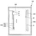
도 1은 본 발명의 일 실시예에 따른 측면 분사형 선형 증발원을 구비한 증착장치를 도시한 개략도이다.1 is a schematic view showing a deposition apparatus having a side spray type linear evaporation source according to an embodiment of the present invention.
도 1을 참조하면, 증착장치(100)는 그의 몸체를 이루는 챔버(200), 기판(S)을 고정시키는 기판 고정수단(500) 및 적어도 하나의 증발원(300)을 구비한다.Referring to FIG. 1, the
상기 기판 고정수단(500)은 상기 챔버(200) 내에 위치하여 상기 기판(S)을 지면에 대해 대략 수직이 되도록 고정한다. 이로써, 중력에 의한 기판 처짐을 방지할 수 있다. 이는 상기 기판(S)이 대형인 경우 더욱 그러하다. 바람직하게는 상기 기판 고정수단(500)은 상기 기판(S)을 지면과 70 내지 110도의 각도를 가지도록 고정한다.The substrate fixing means 500 is located in the
상기 기판(S)의 상기 증발원(300)을 바라보는 면 상에 섀도우 마스크(M)가 설치될 수 있다. 상기 섀도우 마스크(M)는 증착막의 패턴 형상을 결정하는 역할을 한다.A shadow mask M may be installed on a surface of the substrate S facing the
상기 증발원(300)은 증발재료를 저장하고, 상기 저장된 증발재료를 가열하여 증발시킨 후, 증발된 증기를 기판(S) 상으로 분사(effuse)하여 기판(S) 상에 증착 막을 형성하는 기능을 한다. 이 때, 상기 증발원(300)은 상기 증기를 상기 증발원(300)의 일측면을 통해 분사한다.The
이러한 증발원(300)은 증발원 이송 장치(400)에 의해 상하 방향으로 이송될 수 있다. 따라서, 상기 증발원(300)은 상하 방향으로 이송되면서 상기 지면에 대해 실질적으로 수직으로 고정된 기판(S) 상에 증기를 분사시킬 수 있다. 상기 증발원 이송 장치(400)는 볼 스크류(401), 상기 볼 스크류(401)를 회전시키는 모터(403) 및 상기 증발원(300)을 상하 방향으로 안내하기 위한 가이드(402)를 구비한다.The
한편, 상기 증발원(300)은 상기 기판(S)을 가로지르는 방향으로 긴 폭을 갖는 선형 증발원일 수 있다. 이로써, 상기 기판(도 1의 S) 상에 균일한 증착막을 형성할 수 있다. 이 경우, 상기 도가니(360)와 상기 하우징(320) 또한 상기 폭(W)에 대응한 긴 폭을 갖는다.On the other hand, the
또한, 상기 증착장치(100)는 상기 기판(S) 상에 증착되는 증착막의 두께를 측정할 수 있는 두께 측정 장치(미도시)를 더 구비할 수도 있다.In addition, the
상기 챔버(200)에 진공펌프(미도시)가 연결된다. 이로써, 상기 챔버(200) 내부는 진공상태를 유지할 수 있다.A vacuum pump (not shown) is connected to the
도 2는 본 발명의 일 실시예에 따른 측면 분사형 선형 증발원을 나타낸 사시도이고, 도 3은 도 2에 나타낸 측면 분사형 선형 증발원의 일부 구성요소를 나타낸 분해 사시도이고, 도 4는 도 2의 절단선 I-I'를 따라 취해진 단면도이다.2 is a perspective view illustrating a side injection linear evaporation source according to an embodiment of the present invention, FIG. 3 is an exploded perspective view showing some components of the side injection linear evaporation source shown in FIG. 2, and FIG. 4 is a cut line I of FIG. 2. A cross section taken along -I '.
도 2 내지 도 4를 참조하면, 증발원(300)은 일측면, 자세하게는 기판(도 1의 S)을 향하는 측면이 개구된 하우징(320)을 구비한다. 상기 하우징(320)의 내부에 상기 하우징(320)의 개구된 면과 같은 방향의 면이 개구되고, 증발재료 저장공간을 갖는 몸체(368)를 구비하는 도가니(360)가 위치한다. 상기 하우징(320)은 상기 도가니(360)를 감싸는 형태를 갖고, 상기 도가니(360)를 외부 환경으로부터 격리한다.2 to 4, the
상기 증발원(300)은 수직으로 배치된 기판(도 1의 S)을 가로지르는 방향으로 긴 폭(W)을 갖는 선형 증발원이다. 이로써, 상기 기판(도 1의 S) 상에 균일한 증착막을 형성할 수 있다. 이 경우, 상기 도가니(360)와 상기 하우징(320) 또한 상기 폭(W)에 대응한 긴 폭을 갖는다.The
상기 긴 폭을 갖는 도가니(360)는 상기 증발재료 저장공간을 다수개의 부분으로 분할하는 격벽(partition wall; 365)을 구비한다. 이러한 격벽(365)으로 인해 상기 증발원(300)이 좌우 수평을 유지하지 못하더라도 상기 증발재료(D)는 상기 도가니(360) 내에서 어느 한 방향으로 치우치지 않고 균일하게 저장될 수 있다.The
상기 격벽(365)은 상기 도가니 몸체(368)의 바닥면에 연결되고 상기 몸체(368)의 상부면(367)과는 이격된다. 그 결과, 상기 증발재료(D)로부터 증발된 증기는 상기 격벽(365)과 상기 몸체 상부면(367) 사이의 공간을 통해 분할된 저장공간들 사이를 자유롭게 이동할 수 있다. 따라서, 상기 증발재료(D)로부터 증발된 증기의 압력을 상기 도가니(360)의 전체 저장공간들에서 균일하게 분포하도록 할 수 있다. 결과적으로 기판(도 1의 S) 상에 두께의 분포가 균일한 증착막을 형성할 수 있다. 이를 위해, 상기 격벽(365)은 그의 상부의 적어도 일부분에 단차(365a)를 구비하는 것이 바람직하다. 상기 단차(365a)로 인해 상기 격벽(365)은 일부분의 높이가 낮아지고, 상기 격벽(365)의 높이가 낮아진 부분을 통해 상기 증발된 증기는 압력의 분포에 따라 더 자유롭게 이동할 수 있다.The
상기 도가니(360)는 튐 방지턱(spitting preventing protrusion; 363)을 구비한다. 상기 튐 방지턱(363)은 상기 도가니(360)가 가열되어 상기 증발재료(D)가 증발될 때, 상기 증발재료(D)가 튀어(spit) 상기 증발원(300) 바깥으로 나가는 것을 방지하는 역할을 한다. 이를 위해, 상기 튐 방지턱(363)의 높이(HS)는 상기 도가니 몸체(368)의 바닥면으로부터 노즐(351)까지의 높이(HN) 보다 큰 것이 바람직하다. 이러한, 튐 현상은 증발 초기단계 또는 상기 증발재료(D)에 밀도의 변화 등이 발생하였을 때 발생하기 쉬우며, 이러한 튐 현상으로 인해 상기 노즐(351)이 막힐 수 있고, 상기 기판(도 1의 S)이 오염되거나 예기치 않은 증착을 유발할 수 있다. 이는 증착막의 질을 저하시키는 요인이 되기도 한다.The
상기 튐 방지턱(363)은 상기 도가니 몸체(368)의 개구된 면에 인접하여 위치하며, 상기 도가니 몸체(368)와 일체형일 수 있다. 자세하게는 상기 튐 방지턱(363)은 상기 도가니 몸체(368)의 바닥면에 일체형으로 연결될 수 있다. 이로써, 상기 튐 방지턱(363)과 상기 도가니 몸체(368)의 바닥면 사이에 틈이 없다. 따라서, 상기 증발재료(D)가 상기 튐 방지턱(363)과 상기 도가니 몸체(368)의 바닥면 사이의 틈으로 새어나가는 것을 방지할 수 있다. 특히 상기 증발재료(D)가 열에 의해 액화될 수 있는 경우 더욱 그러하다.The
나아가, 상기 격벽(365)과 상기 도가니 몸체(368); 및 상기 격벽(365)과 상 기 튐 방지턱(363)은 일체형으로 연결되는 것이 바람직하다. 이로써, 상기 격벽(365)과 상기 도가니 몸체(368)의 바닥면 사이의 틈 또는 상기 튐 방지턱(363)과 상기 격벽(365) 사이의 틈으로 상기 증발재료(D)가 이동하는 것을 방지할 수 있다. 이는 상기 증발재료(D)가 열에 의해 액화되는 경우 더욱 그러하다.Furthermore, the
나아가, 상기 도가니 몸체(368)의 상부면(367)은 상기 도가니 몸체(368)의 다른 부분(361)에 대해 탈착가능한 것이 바람직하다. 따라서, 상기 저장공간에 증발재료(D)를 용이하게 적재할 수 있다.Further, the
바람직하게는 상기 도가니(360)는 열전도도가 우수한 물질로 형성된다. 구체적으로 상기 도가니(360)은 흑연(graphite)으로 형성될 수 있다. 상기 흑연은 육방정계(hexagonal system)의 다공성 물질로써 단열효율이 매우 우수하다. 따라서 이러한 흑연 도가니는 도가니(360) 내부의 온도를 안정적으로 유지할 수 있다.Preferably, the
상기 도가니(360) 내에 저장되는 증발재료(D)는 유기물일 수 있다. 상기 유기물은 전계발광성 유기물, 정공주입성 유기물, 정공수송성 유기물, 전자수송성 유기물 또는 전자주입성 유기물일 수 있다.The evaporation material D stored in the
상기 도가니(360)의 개구된 측면에 노즐부(350)가 연결된다. 이러한 노즐부(350)는 상기 노즐부(350)를 이루는 몸체(353)와 상기 몸체(353)를 관통하는 노즐(351)을 구비한다. 이 때, 상기 노즐 몸체(353)의 일측은 상기 도가니(360)의 개구된 측면 내에 끼워져 상기 도가니(360)의 개구된 측면을 밀폐하며, 상기 노즐 몸체(353)의 타측은 상기 도가니(360)의 개구된 면의 외측으로 소정길이 연장되어 돌출된다.The
상기 노즐(351)은 상기 증발재료(D)로부터 증발된 기체를 상기 기판(도 1의 S) 상으로 분사하는 역할을 한다. 상기 증발원(300)이 상술한 선형 증발원인 경우, 상기 노즐부(350)는 다수개의 노즐(351)을 구비한다. 이 경우, 상기 노즐들(351)은 상기 노즐부(350)의 중앙부보다 상기 노즐부(350)의 가장자리부에서 더 조밀하게 분포할 수 있다. 이로써, 상기 증발원(300)의 중앙부와 가장자리부에서 분사되는 증기의 량을 균일하게 할 수 있고, 그 결과 상기 기판(도 1의 S) 상에 증착되는 증착막을 균일하게 형성할 수 있다.The
상기 하우징(320) 내에 상기 노즐부(350) 및/또는 상기 도가니(360)를 가열하는 가열부(370)가 배치된다. 상기 가열부(370)로부터 전달된 열에 의해 상기 도가니(360) 내에 저장된 증발재료(D)는 증발되어 상기 노즐(351)을 통해 상기 기판(도 1의 S) 상으로 분사된다. 바람직하게는 상기 가열부(370)는 상기 노즐부(350)가 상기 도가니(360)의 개구된 면으로부터 돌출된 부분에 인접하여 상기 노즐부(350)의 돌출된 부분을 가열한다. 이와 동시에, 상기 가열부(370)는 상기 도가니(360)의 개구된 면과 인접한 부분을 부분 가열할 수 있다. 이로써, 상기 도가니(360)의 개구면과 인접한 부분의 온도가 상기 도가니(360)의 개구면과 먼 부분의 온도보다 높은 분포를 가질 수 있게 한다. 결과적으로, 상기 노즐부(350) 근처에서 증기의 응축을 방지할 수 있다.A
한편, 상기 가열부(370)는 열원인 열선(373)과 열선 지지체(375)를 구비할 수 있다. 상기 열선 지지체(375)는 상기 열선(373)의 처짐을 방지하는 역할을 한다. 나아가, 가열부(370)의 구조는 상기 노즐부(350)를 감싸는 형태의 히터 터널 (heater tunnel) 구조일 수 있다.The
상기 가열부(370)와 상기 하우징(320) 사이에 열 반사판(330)이 개재될 수 있다. 상기 열 반사판(330)은 상기 도가니(360)의 상부면 및 하부면을 따라 연장될 수 있다. 상기 열 반사판(330)은 상기 가열부(370)에서 발생되는 열을 반사할 수 있고, 상기 가열부(370)에서 발생되는 열을 전달받은 상기 노즐부(350)와 상기 도가니(360)로부터 복사되는 열을 반사할 수 있다. 그 결과 열효율을 높일 수 있다.A
또한, 상기 노즐부(350)의 상기 기판(도 1의 S) 방향의 외부면에 열 차단판(340)이 부착될 수 있다. 상기 열 차단판(340)은 노즐부(350)를 통하여 열이 방출되어 상기 기판(도 1의 S) 또는 상기 섀도우 마스크(도 1의 M)에 영향을 미치는 것을 최소화할 수 있다.In addition, a
상기 하우징(320)의 외벽에 단열부재(310)가 설치될 수 있다. 상기 단열부재(310)는 상기 가열부(370)에서 발생된 열 및 상기 노즐부(350)와 상기 도가니(360)로부터 복사된 열이 외부로 방출되는 것을 방지한다.The
이하, 상술한 증발원을 구비하는 증착장치를 사용하여 기판 상에 증착막을 형성하는 방법을 도 1 내지 도 4를 다시 참조하여 설명한다.Hereinafter, a method of forming a deposition film on a substrate using the deposition apparatus having the evaporation source described above will be described with reference to FIGS. 1 to 4 again.
먼저, 증발원(300)의 도가니(360) 내에 증발재료(D)를 적재한다. 자세하게는 도가니 몸체(368)의 상부면(367)을 분리한 후, 증발재료(D)를 적재한다. 이어서, 상기 도가니(360), 노즐부(350), 가열부(370), 열 차단판(340), 열 반사판(330), 하우징(320) 및 단열부재(310)를 조립하여 증발원(300)을 형성하고, 형성된 증발원(300)을 증착장치(100)의 챔버(200) 내에 장착한다.First, the evaporation material D is loaded into the
이어서, 증착장치(100)의 챔버(200) 내에 위치하는 기판 고정수단(500) 상에 기판(S)을 장착한다. 상기 기판(S)은 화소전극이 형성된 유기전계발광소자기판 일 수 있다.Subsequently, the substrate S is mounted on the substrate fixing means 500 positioned in the
이어서, 상기 노즐부(350) 및 상기 도가니(360)를 상기 가열부(370)를 사용하여 가열한다. 이 때, 상기 도가니(360) 내에 저장된 증발재료(D)는 가열에 의해 증발되어 증기가 되고, 이러한 증기는 노즐(351)을 통해 상기 기판(S) 상으로 분사된다. 이 때, 상기 증발재료(D)로부터 증발된 증기는 격벽(365)과 상기 몸체 상부면(367) 사이의 공간을 통해 분할된 저장공간들 사이를 자유롭게 이동하여, 상기 증발재료(D)로부터 증발된 증기의 압력을 상기 도가니(360)의 전체 저장공간들에서 균일하게 분포하도록 할 수 있다. 결과적으로 기판(도 1의 S) 상에 두께의 분포가 균일한 증착막을 형성할 수 있다. 상기 격벽(365)이 그의 상부의 적어도 일부분에 단차(365a)를 구비하는 경우, 증기의 압력은 상기 도가니(360)의 전체 저장공간들에서 더 균일하게 분포할 수 있다.Subsequently, the
상기 노즐(351)을 통해 상기 기판(S) 상으로 분사된 증기는 상기 기판(S) 상에 증착되어 증착막을 형성한다. 이 때, 상기 기판(S) 상에 섀도우 마스크(M)를 장착한 경우, 상기 분사된 증기는 상기 섀도우 마스크(M)의 개구부를 통해서 상기 기판(S) 상에 증착되므로 패턴을 갖는 증착막을 형성할 수 있다.The vapor injected onto the substrate S through the
이 과정에서 상기 증발원 이송 장치(400)를 사용하여 상기 증발원(300)을 상하방향으로 이송시킴으로써, 상기 기판(S) 상에 균일한 증착막을 형성할 수 있다.In this process, by using the evaporation
상술한 바와 같이 본 발명에 따르면, 도가니는 증발재료 저장공간을 다수개로 분할하는 격벽을 구비함으로써, 증발재료는 상기 도가니 내에서 어느 한 방향으로 치우치지 않고 균일하게 저장될 수 있다. 나아가, 상기 격벽은 상기 도가니 몸체의 바닥면에 연결되고 상부면에는 이격됨으로써, 상기 증발재료로부터 증발된 증기의 압력을 상기 도가니의 전체 저장공간들에서 균일하게 분포하도록 할 수 있다. 결과적으로 기판 상에 두께의 분포가 균일한 증착막을 형성할 수 있다.As described above, according to the present invention, the crucible includes partition walls for dividing the evaporation material storage space into a plurality, so that the evaporation material can be uniformly stored in the crucible without being biased in any direction. Further, the partition wall is connected to the bottom surface of the crucible body and spaced apart from the upper surface, so that the pressure of the vapor evaporated from the evaporation material can be evenly distributed in the entire storage spaces of the crucible. As a result, a deposition film with a uniform thickness distribution can be formed on the substrate.
상기에서는 본 발명의 바람직한 실시예를 참조하여 설명하였지만, 해당 기술 분야의 숙련된 당업자는 하기의 특허 청구의 범위에 기재된 본 발명의 사상 및 영역으로부터 벗어나지 않는 범위 내에서 본 발명을 다양하게 수정 및 변경시킬 수 있음을 이해할 수 있을 것이다.Although described above with reference to a preferred embodiment of the present invention, those skilled in the art will be variously modified and changed within the scope of the invention without departing from the spirit and scope of the invention described in the claims below I can understand that you can.
Claims (22)
Translated fromKoreanPriority Applications (1)
| Application Number | Priority Date | Filing Date | Title |
|---|---|---|---|
| KR1020050016095AKR100635496B1 (en) | 2005-02-25 | 2005-02-25 | Side spray type linear evaporation source having a partition and vapor deposition apparatus having the evaporation source |
Applications Claiming Priority (1)
| Application Number | Priority Date | Filing Date | Title |
|---|---|---|---|
| KR1020050016095AKR100635496B1 (en) | 2005-02-25 | 2005-02-25 | Side spray type linear evaporation source having a partition and vapor deposition apparatus having the evaporation source |
Publications (2)
| Publication Number | Publication Date |
|---|---|
| KR20060094711A KR20060094711A (en) | 2006-08-30 |
| KR100635496B1true KR100635496B1 (en) | 2006-10-17 |
Family
ID=37602448
Family Applications (1)
| Application Number | Title | Priority Date | Filing Date |
|---|---|---|---|
| KR1020050016095AExpired - LifetimeKR100635496B1 (en) | 2005-02-25 | 2005-02-25 | Side spray type linear evaporation source having a partition and vapor deposition apparatus having the evaporation source |
Country Status (1)
| Country | Link |
|---|---|
| KR (1) | KR100635496B1 (en) |
Cited By (1)
| Publication number | Priority date | Publication date | Assignee | Title |
|---|---|---|---|---|
| KR20150145466A (en) | 2014-06-19 | 2015-12-30 | 최현범 | Linear evaporating source |
Families Citing this family (5)
| Publication number | Priority date | Publication date | Assignee | Title |
|---|---|---|---|---|
| WO2009134041A2 (en)* | 2008-04-29 | 2009-11-05 | Sunic System. Ltd. | Evaporator and vacuum deposition apparatus having the same |
| KR101094299B1 (en) | 2009-12-17 | 2011-12-19 | 삼성모바일디스플레이주식회사 | Linear evaporation source and deposition apparatus comprising the same |
| KR101182265B1 (en)* | 2009-12-22 | 2012-09-12 | 삼성디스플레이 주식회사 | Evaporation Source and Deposition Apparatus having the same |
| CN107002223B (en)* | 2014-12-05 | 2019-11-05 | 应用材料公司 | Material deposition system and method for the deposition materials in material deposition system |
| KR102070865B1 (en)* | 2015-09-15 | 2020-01-29 | 주식회사 원익아이피에스 | Linear source and substrate processing system having same |
Citations (2)
| Publication number | Priority date | Publication date | Assignee | Title |
|---|---|---|---|---|
| WO2001031081A1 (en)* | 1999-10-22 | 2001-05-03 | Kurt J. Lesker Company | Method and apparatus for coating a substrate in a vacuum |
| JP2004137583A (en) | 2002-10-21 | 2004-05-13 | Tohoku Pioneer Corp | Vacuum deposition equipment |
- 2005
- 2005-02-25KRKR1020050016095Apatent/KR100635496B1/ennot_activeExpired - Lifetime
Patent Citations (2)
| Publication number | Priority date | Publication date | Assignee | Title |
|---|---|---|---|---|
| WO2001031081A1 (en)* | 1999-10-22 | 2001-05-03 | Kurt J. Lesker Company | Method and apparatus for coating a substrate in a vacuum |
| JP2004137583A (en) | 2002-10-21 | 2004-05-13 | Tohoku Pioneer Corp | Vacuum deposition equipment |
Non-Patent Citations (1)
| Title |
|---|
| 1020050016095 - 669438 |
Cited By (1)
| Publication number | Priority date | Publication date | Assignee | Title |
|---|---|---|---|---|
| KR20150145466A (en) | 2014-06-19 | 2015-12-30 | 최현범 | Linear evaporating source |
Also Published As
| Publication number | Publication date |
|---|---|
| KR20060094711A (en) | 2006-08-30 |
Similar Documents
| Publication | Publication Date | Title |
|---|---|---|
| KR101094299B1 (en) | Linear evaporation source and deposition apparatus comprising the same | |
| KR101182265B1 (en) | Evaporation Source and Deposition Apparatus having the same | |
| JP4440837B2 (en) | Evaporation source and vapor deposition apparatus employing the same | |
| JP5155941B2 (en) | Evaporation source assembly and vapor deposition apparatus using the same | |
| JP5261404B2 (en) | Evaporation source and vapor deposition apparatus equipped with the same | |
| CN100567556C (en) | Evaporation source and evaporation device using same | |
| KR102073717B1 (en) | Crucible for linear evaporation source and Linear evaporation source having the same | |
| KR101938219B1 (en) | Crucible for linear evaporation source and Linear evaporation source having the same | |
| KR100635496B1 (en) | Side spray type linear evaporation source having a partition and vapor deposition apparatus having the evaporation source | |
| KR101131599B1 (en) | Evaporator and vacuum evaporation apparatus having the same | |
| KR100666572B1 (en) | Organics Evaporator | |
| KR20060094723A (en) | 측면 side injection type evaporation source having a jaw and a vapor deposition apparatus having the evaporation source | |
| KR102454832B1 (en) | Linear Deposition Source | |
| KR101660393B1 (en) | Evaporation source and Apparatus for deposition having the same | |
| KR101866956B1 (en) | Crucible for linear evaporation source and Linear evaporation source having the same | |
| KR20200033458A (en) | Linear source and substrate processing system having the same | |
| KR101893972B1 (en) | Deposition Chamber | |
| KR102759534B1 (en) | Deposition device | |
| KR20150086781A (en) | Large capacity evaporation source and Deposition apparatus including the same | |
| KR20170057646A (en) | Apparatus of deposition having radiation angle controlling plate | |
| KR100666570B1 (en) | Organic material evaporation source and organic material deposition apparatus | |
| KR100667076B1 (en) | Organic material evaporation source and organic material deposition apparatus | |
| KR102708291B1 (en) | Linear Deposition Source | |
| KR100645687B1 (en) | Crucible of evaporation apparatus and evaporation source using the same | |
| KR20060099974A (en) | Evaporation Source and Deposition Device Equipped with the Same |
Legal Events
| Date | Code | Title | Description |
|---|---|---|---|
| A201 | Request for examination | ||
| PA0109 | Patent application | St.27 status event code:A-0-1-A10-A12-nap-PA0109 | |
| PA0201 | Request for examination | St.27 status event code:A-1-2-D10-D11-exm-PA0201 | |
| D13-X000 | Search requested | St.27 status event code:A-1-2-D10-D13-srh-X000 | |
| D14-X000 | Search report completed | St.27 status event code:A-1-2-D10-D14-srh-X000 | |
| E902 | Notification of reason for refusal | ||
| PE0902 | Notice of grounds for rejection | St.27 status event code:A-1-2-D10-D21-exm-PE0902 | |
| P11-X000 | Amendment of application requested | St.27 status event code:A-2-2-P10-P11-nap-X000 | |
| P13-X000 | Application amended | St.27 status event code:A-2-2-P10-P13-nap-X000 | |
| PG1501 | Laying open of application | St.27 status event code:A-1-1-Q10-Q12-nap-PG1501 | |
| E701 | Decision to grant or registration of patent right | ||
| PE0701 | Decision of registration | St.27 status event code:A-1-2-D10-D22-exm-PE0701 | |
| GRNT | Written decision to grant | ||
| PR0701 | Registration of establishment | St.27 status event code:A-2-4-F10-F11-exm-PR0701 | |
| PR1002 | Payment of registration fee | St.27 status event code:A-2-2-U10-U11-oth-PR1002 Fee payment year number:1 | |
| PG1601 | Publication of registration | St.27 status event code:A-4-4-Q10-Q13-nap-PG1601 | |
| PN2301 | Change of applicant | St.27 status event code:A-5-5-R10-R11-asn-PN2301 | |
| PN2301 | Change of applicant | St.27 status event code:A-5-5-R10-R14-asn-PN2301 | |
| R18-X000 | Changes to party contact information recorded | St.27 status event code:A-5-5-R10-R18-oth-X000 | |
| R18-X000 | Changes to party contact information recorded | St.27 status event code:A-5-5-R10-R18-oth-X000 | |
| PR1001 | Payment of annual fee | St.27 status event code:A-4-4-U10-U11-oth-PR1001 Fee payment year number:4 | |
| R18-X000 | Changes to party contact information recorded | St.27 status event code:A-5-5-R10-R18-oth-X000 | |
| PR1001 | Payment of annual fee | St.27 status event code:A-4-4-U10-U11-oth-PR1001 Fee payment year number:5 | |
| PR1001 | Payment of annual fee | St.27 status event code:A-4-4-U10-U11-oth-PR1001 Fee payment year number:6 | |
| PN2301 | Change of applicant | St.27 status event code:A-5-5-R10-R11-asn-PN2301 | |
| PN2301 | Change of applicant | St.27 status event code:A-5-5-R10-R14-asn-PN2301 | |
| FPAY | Annual fee payment | Payment date:20121008 Year of fee payment:7 | |
| PR1001 | Payment of annual fee | St.27 status event code:A-4-4-U10-U11-oth-PR1001 Fee payment year number:7 | |
| FPAY | Annual fee payment | Payment date:20130930 Year of fee payment:8 | |
| PR1001 | Payment of annual fee | St.27 status event code:A-4-4-U10-U11-oth-PR1001 Fee payment year number:8 | |
| R18-X000 | Changes to party contact information recorded | St.27 status event code:A-5-5-R10-R18-oth-X000 | |
| FPAY | Annual fee payment | Payment date:20141001 Year of fee payment:9 | |
| PR1001 | Payment of annual fee | St.27 status event code:A-4-4-U10-U11-oth-PR1001 Fee payment year number:9 | |
| R18-X000 | Changes to party contact information recorded | St.27 status event code:A-5-5-R10-R18-oth-X000 | |
| PR1001 | Payment of annual fee | St.27 status event code:A-4-4-U10-U11-oth-PR1001 Fee payment year number:10 | |
| L13-X000 | Limitation or reissue of ip right requested | St.27 status event code:A-2-3-L10-L13-lim-X000 | |
| U15-X000 | Partial renewal or maintenance fee paid modifying the ip right scope | St.27 status event code:A-4-4-U10-U15-oth-X000 | |
| P22-X000 | Classification modified | St.27 status event code:A-4-4-P10-P22-nap-X000 | |
| PR1001 | Payment of annual fee | St.27 status event code:A-4-4-U10-U11-oth-PR1001 Fee payment year number:11 | |
| P22-X000 | Classification modified | St.27 status event code:A-4-4-P10-P22-nap-X000 | |
| FPAY | Annual fee payment | Payment date:20170928 Year of fee payment:12 | |
| PR1001 | Payment of annual fee | St.27 status event code:A-4-4-U10-U11-oth-PR1001 Fee payment year number:12 | |
| FPAY | Annual fee payment | Payment date:20181001 Year of fee payment:13 | |
| PR1001 | Payment of annual fee | St.27 status event code:A-4-4-U10-U11-oth-PR1001 Fee payment year number:13 | |
| FPAY | Annual fee payment | Payment date:20191001 Year of fee payment:14 | |
| PR1001 | Payment of annual fee | St.27 status event code:A-4-4-U10-U11-oth-PR1001 Fee payment year number:14 | |
| PR1001 | Payment of annual fee | St.27 status event code:A-4-4-U10-U11-oth-PR1001 Fee payment year number:15 | |
| R18-X000 | Changes to party contact information recorded | St.27 status event code:A-5-5-R10-R18-oth-X000 | |
| PR1001 | Payment of annual fee | St.27 status event code:A-4-4-U10-U11-oth-PR1001 Fee payment year number:16 | |
| PR1001 | Payment of annual fee | St.27 status event code:A-4-4-U10-U11-oth-PR1001 Fee payment year number:17 | |
| PR1001 | Payment of annual fee | St.27 status event code:A-4-4-U10-U11-oth-PR1001 Fee payment year number:18 | |
| P22-X000 | Classification modified | St.27 status event code:A-4-4-P10-P22-nap-X000 | |
| PR1001 | Payment of annual fee | St.27 status event code:A-4-4-U10-U11-oth-PR1001 Fee payment year number:19 | |
| PC1801 | Expiration of term | St.27 status event code:N-4-6-H10-H14-oth-PC1801 Not in force date:20250226 Ip right cessation event data comment text:Termination Category : EXPIRATION_OF_DURATION |