KR100633061B1 - Network system and its formal address allocation method - Google Patents
Network system and its formal address allocation methodDownload PDFInfo
- Publication number
- KR100633061B1 KR100633061B1KR20040079982AKR20040079982AKR100633061B1KR 100633061 B1KR100633061 B1KR 100633061B1KR 20040079982 AKR20040079982 AKR 20040079982AKR 20040079982 AKR20040079982 AKR 20040079982AKR 100633061 B1KR100633061 B1KR 100633061B1
- Authority
- KR
- South Korea
- Prior art keywords
- address
- terminal device
- formal
- terminal
- formal address
- Prior art date
- Legal status (The legal status is an assumption and is not a legal conclusion. Google has not performed a legal analysis and makes no representation as to the accuracy of the status listed.)
- Expired - Fee Related
Links
Images


Classifications
- H—ELECTRICITY
- H04—ELECTRIC COMMUNICATION TECHNIQUE
- H04L—TRANSMISSION OF DIGITAL INFORMATION, e.g. TELEGRAPHIC COMMUNICATION
- H04L12/00—Data switching networks
- H04L12/28—Data switching networks characterised by path configuration, e.g. LAN [Local Area Networks] or WAN [Wide Area Networks]
- H—ELECTRICITY
- H04—ELECTRIC COMMUNICATION TECHNIQUE
- H04L—TRANSMISSION OF DIGITAL INFORMATION, e.g. TELEGRAPHIC COMMUNICATION
- H04L12/00—Data switching networks
- H04L12/28—Data switching networks characterised by path configuration, e.g. LAN [Local Area Networks] or WAN [Wide Area Networks]
- H04L12/40—Bus networks
- H04L12/403—Bus networks with centralised control, e.g. polling
- H—ELECTRICITY
- H04—ELECTRIC COMMUNICATION TECHNIQUE
- H04L—TRANSMISSION OF DIGITAL INFORMATION, e.g. TELEGRAPHIC COMMUNICATION
- H04L41/00—Arrangements for maintenance, administration or management of data switching networks, e.g. of packet switching networks
- H—ELECTRICITY
- H04—ELECTRIC COMMUNICATION TECHNIQUE
- H04L—TRANSMISSION OF DIGITAL INFORMATION, e.g. TELEGRAPHIC COMMUNICATION
- H04L61/00—Network arrangements, protocols or services for addressing or naming
- H04L61/50—Address allocation
- H04L61/5038—Address allocation for local use, e.g. in LAN or USB networks, or in a controller area network [CAN]
- H—ELECTRICITY
- H04—ELECTRIC COMMUNICATION TECHNIQUE
- H04L—TRANSMISSION OF DIGITAL INFORMATION, e.g. TELEGRAPHIC COMMUNICATION
- H04L12/00—Data switching networks
- H04L12/28—Data switching networks characterised by path configuration, e.g. LAN [Local Area Networks] or WAN [Wide Area Networks]
- H04L12/2803—Home automation networks
- H04L2012/2847—Home automation networks characterised by the type of home appliance used
- H04L2012/285—Generic home appliances, e.g. refrigerators
- H—ELECTRICITY
- H04—ELECTRIC COMMUNICATION TECHNIQUE
- H04L—TRANSMISSION OF DIGITAL INFORMATION, e.g. TELEGRAPHIC COMMUNICATION
- H04L2101/00—Indexing scheme associated with group H04L61/00
- H04L2101/60—Types of network addresses
- H04L2101/604—Address structures or formats
Landscapes
- Engineering & Computer Science (AREA)
- Computer Networks & Wireless Communication (AREA)
- Signal Processing (AREA)
- Small-Scale Networks (AREA)
- Data Exchanges In Wide-Area Networks (AREA)
Abstract
Translated fromKorean
Description
Translated fromKorean도 1은 도 1은 일반적인 빌딩 설비 감시 시스템의 구성도,1 is a block diagram of a general building equipment monitoring system,
도 2는 종래에 자동으로 정식어드레스를 설정하기 위한 흐름도,2 is a flowchart for automatically setting a formal address in the prior art;
도 3은 종래에 중복이 발생할 때의 정식어드레스를 할당하기 위한 흐름도,3 is a flowchart for allocating a formal address when a duplication occurs in the prior art;
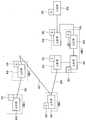
도 4는 본 발명에 따른 네트워크시스템의 구성도4 is a configuration diagram of a network system according to the present invention;
도 5는 본 발명에 따른 네트워크시스템에서 실외기와 각 실내기의 내부 구성 및 실외기와 각 실내기의 접속도,5 is a view illustrating an internal configuration of an outdoor unit and each indoor unit and a connection diagram between the outdoor unit and each indoor unit in a network system according to the present invention;
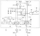
도 6 및 도 7은 인터페이스회로의 구성도,6 and 7 are configuration diagrams of an interface circuit;
도 8은 정식어드레스의 할당 진행 개략도,8 is a schematic diagram showing the allocation of formal addresses;
도 9는 본 발명에 따라 배선 순서 일부 미확인시에 자동적으로 정식어드레스가 할당된 네트워크시스템의 구성도,9 is a configuration diagram of a network system in which formal addresses are automatically assigned when a part of wiring order is not confirmed in accordance with the present invention;
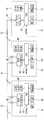
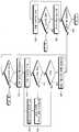
도 10 및 도 11은 마스터-슬레이브 방식의 네트워크시스템에서 정식어드레스를 할당하기 위한 실외기 및 실내기 각각의 제어흐름도,10 and 11 are control flow charts of each of the outdoor unit and the indoor unit for allocating formal addresses in a master-slave network system;
도 12 및 도 13은 이벤트 방식의 네트워크시스템에서 정식어드레스를 할당하기 위한 실외기 및 실내기 각각의 제어흐름도이다.12 and 13 are control flowcharts of each of the outdoor unit and the indoor unit for allocating formal addresses in the event-based network system.
* 도면의 주요 부분에 대한 부호의 설명* Explanation of symbols for the main parts of the drawings
10 : 실외기11 : 딥스위치10: outdoor unit 11: dip switch
12 : 정식어드레스14 : 실내기12: formal address 14: indoor unit
15 : 배선16 : 실외기측 CPU15: wiring 16: outdoor unit CPU
17 : 실외기측 EEPROM19 : 실외기측 제어로직회로17: Outdoor unit side EEPROM 19: Outdoor unit side control logic circuit
19 : 실외기측 통신접속부20 : 실내기측 CPU19: outdoor unit communication connection part 20: indoor unit CPU
22 : 실내기측 EEPROM24 : LED 또는 LCD22: Indoor unit EEPROM 24: LED or LCD
26 : 인터페이스회로28 : 실내기측 제어로직회로26: interface circuit 28: indoor unit control logic circuit
30 : 실내기측 통신접속부32 : 릴레이30: indoor unit communication connection part 32: relay
본 발명은, 네트워크시스템 및 그 정식어드레스 할당방법에 관한 것으로서, 보다 상세하게는, 정식어드레스를 자동적으로 설정하고, 설정된 정식어드레스를 작업자가 용이하게 추측할 수 있도록 한 네트워크시스템 및 그 정식어드레스 할당방법에 관한 것이다.The present invention relates to a network system and a method for allocating the formal address, and more particularly, a network system and a method for allocating the formal address automatically so that an operator can easily guess the formal address. It is about.
일반적으로 빌딩 설비 감시 시스템과 같은 네트워크시스템은 중앙제어장치와, 중앙제어장치의 제어를 받는 복수의 단말장치를 포함한다.In general, a network system such as a building facility monitoring system includes a central control unit and a plurality of terminal devices controlled by the central control unit.
도 1은 일반적인 빌딩 설비 감시 시스템의 구성도를 나타낸 것이다.1 is a block diagram of a general building equipment monitoring system.
도 1에 도시된 바와 같이, 일반적인 빌딩 설비 감시 시스템은, 시스템 전체를 제어하는 중앙제어장치인 실외기(100)와, 정식어드레스(102)를 가지며 실외기 (100)의 제어를 받는 복수의 실내기(104)를 포함한다. 여기서, 복수의 실내기(104)는 실외기(100)로부터 소정의 배선(105)경로를 따라 순차적으로 연결되어 있다.As shown in FIG. 1, a general building equipment monitoring system includes an
도 1에 도시된 각 정식어드레스(102)는 작업자에 의해 딥스위치(DIP-SW) 등으로 각 실내기(104)에 직접 설정될 수도 있으며, 자동으로 설정될 수도 있다.Each
도 2는 자동으로 정식어드레스(102)를 설정하기 위한 흐름도를 나타낸 것이다. 참고로, 도 2는 마스터(master)-슬레이브(slave) 방식의 네트워크시스템을 도시한 것이다.2 shows a flowchart for automatically setting the
도 2에 도시된 바와 같이, 정식어드레스(102)를 할당하기 위해 마스터인 실외기(100)가 실내기(104)에 응답을 요청하면, 슬레이브인 실내기(104)는 자신의 정식어드레스(102)를 자동으로 할당받기 위하여 자신의 맥 어드레스(MAC address)나 스스로 만든 난수를 이용하여 응답 지연시간(wait time)을 형성한다(110). 이 응답 지연시간 후에 실내기(104)는 마스터인 실외기(100)로 응답을 시도한다. 실내기(104)로부터 응답을 받은 실외기(100)는 가장 빠른 시간에 응답한, 즉 응답 지연시간이 가장 짧은 실내기(104)부터 차례로 정식어드레스(102)를 할당한다(112). 이에, 실내기(104)에서는 정식어드레스(102)를 확정한다(114).As shown in FIG. 2, when the
도 3은 중복이 발생할 때의 정식어드레스(102)를 할당하기 위한 흐름도를 나타낸 것이다.3 shows a flowchart for allocating the
도 3에 도시된 바와 같이, 실내기(104)는 먼저 자신의 임시어드레스를 설정한다(116). 그리고, 스스로 만든 난수에 의한 지연시간 후에 실내기(104)는 마스터인 실외기(100)로 응답을 시도한다(118). 실외기(100)는 중복되는 어드레스가 있는 지 확인한다. 중복이 발생한 것으로 판단되면, 실내기(104)에 이를 알린다. 그러면, 실내기(104)는 임시어드레스를 다시 설정하여 실외기(100)로 응답한다(120). 실외기(100)는 중복이 발생하지 않으면 재설정한 임시어드레스를 정식어드레스(102)로 확정하여 실내기(104)에 할당한다(122).As shown in FIG. 3, the
그런데, 이와 같은 종래의 정식어드레스(102)의 설정방법은 다음과 같은 문제점이 있다.However, the conventional method for setting the
딥스위치 등으로 각 실내기(104)에 직접 정식어드레스(102)를 설정하는 방법은 실내기(104)가 천정과 지붕과의 사이 등 작업성이 좋지 않은 위치에 존재하게 되면 정식어드레스(102)의 설정 및 확인이 용이하지 않다.The method of setting the
그리고, 자동으로 정식어드레스(102)를 할당하는 방법은 작업자가 실제로 어느 실내기(104)에 정식어드레스(102)가 할당되었는지 알기가 어렵다.And, in the method of automatically assigning the
물론, 정식어드레스(102)의 설정 확인을 용이하게 할 수 있도록 실내기(104) 패널에 설정표시장치를 설치할 수도 있으나, 이러한 경우 비용이 증대하는 단점이 있다.Of course, the setting display device may be installed on the panel of the
따라서, 본 발명의 목적은, 정식어드레스를 자동적으로 설정하고, 설정된 정식어드레스를 작업자가 용이하게 추측할 수 있도록 한 네트워크시스템 및 그 정식어드레스 할당방법을 제공하는 것이다.It is therefore an object of the present invention to provide a network system and a method for allocating formal addresses, which automatically set formal addresses and allow an operator to easily guess the set formal addresses.
상기 목적은, 본 발명에 따라, 중앙제어장치와, 상기 중앙제어장치로부터 소 정의 배선경로를 따라 순차적으로 연결되어 상기 중앙제어장치와 통신하는 복수의 단말장치를 포함하는 네트워크시스템의 정식어드레스 할당방법에 있어서, 각각의 상기 단말장치가 상기 배선경로를 따라 순차적으로 상기 중앙제어장치에 접속하는 단계와; 상기 중앙제어장치에서, 접속되는 상기 단말장치에 상기 정식어드레스를 순차적으로 할당하는 단계를 포함하는 것을 특징으로 하는 정식어드레스 할당방법에 의해 달성된다.The above object is, according to the present invention, a formal address allocation method of a network system including a central control device and a plurality of terminal devices sequentially connected along a predetermined wiring path from the central control device to communicate with the central control device. Connecting each of the terminal devices to the central control device sequentially along the wiring path; In the central control device, the formal address assignment method comprising the step of sequentially assigning the formal address to the terminal device to be connected.
여기서, 상기 중앙제어장치에서 상기 중앙제어장치에 연결된 상기 단말장치의 정식어드레스 정보를 갖는 라우팅테이블이 존재하는지를 판단하는 단계와; 상기 라우팅테이블이 존재하지 아니하면 상기 단말장치에 상기 정식어드레스를 순차적으로 할당하는 단계를 더 포함한다.Determining, by the central controller, whether a routing table having formal address information of the terminal device connected to the central controller exists; If the routing table does not exist, the step of sequentially assigning the formal address to the terminal device.
그리고, 상기 정식어드레스를 순차적으로 할당하는 단계는, 상기 라우팅테이블이 존재하지 않는 경우, 순차적으로 상기 중앙제어장치에 접속되는 상기 단말장치가 각각 임시어드레스를 갖는지를 판단하는 단계와; 상기 단말장치가 상기 임시어드레스를 갖는 경우, 상기 배선경로에 위치한 순서에 해당하는 상기 정식어드레스를 상기 단말장치에 할당하는 단계를 포함할 수 있다.The step of sequentially allocating the formal address may include determining whether the terminal devices sequentially connected to the central control device have temporary addresses when the routing table does not exist; If the terminal device has the temporary address, the method may include assigning the formal address corresponding to the order of being located in the wiring path to the terminal device.
또한, 상기 정식어드레스를 순차적으로 할당하는 단계는, 상기 라우팅테이블이 존재하지 않는 경우, 상기 중앙제어장치에서 상기 단말장치로부터 상기 정식어드레스 설정 요구가 있는지를 판단하는 단계와; 상기 단말장치로부터 상기 정식어드레스 설정 요구가 있는 경우, 상기 중앙제어장치가 상기 배선경로에 위치한 순서에 해당하는 상기 정식어드레스를 상기 단말장치에 할당하는 단계를 포함할 수도 있다.The step of sequentially allocating the formal address may include: determining whether there is a formal address setting request from the terminal apparatus in the central control apparatus when the routing table does not exist; When the formal address setting request is received from the terminal device, the central controller may include assigning the formal address corresponding to the order of being located in the wiring path to the terminal device.
상기 라우팅테이블이 존재하는 경우, 상기 중앙제어장치에서 상기 라우팅테이블의 상기 단말장치의 정식어드레스 정보를 기초로 상기 단말장치와의 통신을 확인하는 단계와; 상기 중앙제어장치에서 상기 단말장치와의 통신이 비정상적인 것으로 판단한 경우, 상기 단말장치가 상기 임시어드레스를 갖는지를 판단하는 단계와; 상기 단말장치가 상기 임시어드레스를 갖는 경우, 이미 할당된 상기 정식어드레스 다음의 정식어드레스를 상기 단말장치에 할당하는 단계와; 상기 단말장치에 할당된 상기 정식어드레스에 기초하여 상기 라우팅테이블의 포인터를 갱신하는 단계를 포함함으로써, 새로이 접속된 단말장치의 정식어드레스를 할당하는 것이 가능하도록 한다.When the routing table exists, confirming, by the central controller, communication with the terminal device based on formal address information of the terminal device of the routing table; Determining, by the central controller, whether the terminal device has the temporary address when it is determined that the communication with the terminal device is abnormal; If the terminal apparatus has the temporary address, allocating a formal address following the already assigned formal address to the terminal apparatus; Updating the pointer of the routing table based on the formal address assigned to the terminal device, thereby making it possible to allocate the formal address of the newly connected terminal device.
그리고, 상기 단말장치와의 통신이 비정상적인 경우 상기 단말장치가 상기 임시어드레스를 갖는지를 판단하는 단계에서 상기 단말장치가 상기 임시어드레스를 갖지 아니하면, 상기 중앙제어장치에서 상기 단말장치가 제거되거나 전원이 오프된 것으로 인식하는 단계와; 상기 전원이 오프된 단말장치를 체크하여 상기 라우팅테이블을 갱신하는 단계를 포함하는 것이 바람직하다.If the terminal apparatus does not have the temporary address in the step of determining whether the terminal apparatus has the temporary address when the communication with the terminal apparatus is abnormal, the terminal apparatus is removed from the central controller or power is supplied. Recognizing it is off; And checking the terminal apparatus of which power is turned off, and updating the routing table.
상기 라우팅테이블이 존재하는 경우, 상기 중앙제어장치에서 상기 라우팅테이블의 상기 단말장치의 정식어드레스 정보를 기초로 상기 단말장치와의 통신을 확인하는 단계와; 상기 중앙제어장치에서 상기 단말장치와의 통신이 비정상적인 것으로 판단한 경우, 상기 중앙제어장치에서 상기 단말장치로부터 상기 정식어드레스 설정 요구가 있는지를 판단하는 단계와; 상기 단말장치로부터 상기 정식어드레스 설정 요구가 있는 경우, 상기 중앙제어장치가 이미 할당된 상기 정식어드레스 다음의 정식어드레스를 상기 단말장치에 할당하는 단계와; 상기 단말장치에 할당된 상기 정식어드레스에 기초하여 상기 라우팅테이블의 포인터를 갱신하는 단계를 포함할 수도 있다.When the routing table exists, confirming, by the central controller, communication with the terminal device based on formal address information of the terminal device of the routing table; Determining, by the central controller, whether there is a formal address setting request from the terminal when the central controller determines that the communication with the terminal is abnormal; Assigning, by the central controller, a formal address following the formal address that has already been allocated to the terminal apparatus when the formal address setting request is received from the terminal apparatus; The method may include updating a pointer of the routing table based on the formal address allocated to the terminal device.
상기 단말장치와의 통신이 비정상적인 경우 상기 중앙제어장치에서 상기 단말장치로부터 상기 정식어드레스 설정 요구가 없으면, 상기 중앙제어장치에서 상기 단말장치가 제거되거나 전원이 오프된 것으로 인식하는 단계와; 상기 전원이 오프된 단말장치를 체크하여 상기 라우팅테이블을 갱신하는 단계를 포함하는 것이 바람직하다.Recognizing that the terminal device is removed or powered off in the central control device when there is no formal address setting request from the terminal device when the communication with the terminal device is abnormal; And checking the terminal apparatus of which power is turned off, and updating the routing table.
상기 단말장치는 자신이 상기 임시어드레스를 가진 경우, 상기 중앙제어장치로 상기 정식어드레스 설정 요구를 행하는 단계를 포함한다.The terminal device includes the step of making the formal address setting request to the central controller when the terminal device has the temporary address.
상기 단말장치가 상기 임시어드레스를 갖지 아니한 경우 상기 배선경로 상에 위치한 다음 상기 단말장치와 상기 중앙제어장치가 접속되도록 하는 단계를 포함하는 것이 바람직하다.If the terminal device does not have the temporary address, it is preferable to include the step of connecting the next terminal device and the central control device located on the wiring path.
한편, 상기 목적은 본 발명의 다른 분야에 따르면, 중앙제어장치와, 상기 중앙제어장치로부터 소정의 배선경로를 따라 순차적으로 연결되어 상기 중앙제어장치와 통신하는 복수의 단말장치를 포함하는 네트워크시스템에 있어서, 상기 단말장치는, 상기 중앙제어장치 및 상기 배선경로 상에 위치한 다음 상기 단말장치와 각각 접속하기 위한 복수의 통신접속부와, 상기 중앙제어장치와 상기 배선경로 상에 위치한 다음 상기 단말장치 중 어느 하나와 접속하기 위해 상기 통신접속부의 접속경 로를 변경하는 인터페이스부와, 자신의 어드레스가 임시어드레스인지를 판단하여 상기 임시어드레스인 경우 상기 중앙제어장치와 접속되도록 하고, 상기 임시어드레스가 아닌 경우 상기 배선경로 상의 다음 상기 단말장치와 접속되도록 상기 인터페이스부를 제어하는 제어부를 가지며, 상기 중앙제어장치는, 상기 통신접속부를 통해 접속되는 상기 단말장치에 정식어드레스를 순차적으로 할당하는 것을 특징으로 하는 네트워크시스템에 의해서도 달성된다.According to another aspect of the present invention, there is provided a network system including a central control device and a plurality of terminal devices sequentially connected from the central control device along a predetermined wiring path to communicate with the central control device. The terminal apparatus may include a plurality of communication connection units for connecting to each of the central control apparatus and the next terminal apparatus located on the wiring path, and any one of the next terminal apparatus located on the central control apparatus and the wiring path. The interface unit for changing the connection path of the communication connection unit to connect with one, and determines whether the address is a temporary address to be connected to the central control unit in the case of the temporary address, if the temporary address is not The interface unit may be connected to be connected to the next terminal device on a wiring path. Having a control unit for the central control device, it is achieved by a network system, characterized in that allocating a full address in sequence to the terminal device that is connected via the communication connection.
상기 통신접속부를 통해 상기 단말장치가 상기 배선경로를 따라 추가로 접속되는 경우, 상기 중앙제어장치는 상기 단말장치에 이미 할당된 상기 정식어드레스 다음의 정식어드레스를 할당하는 것이 가능하다.When the terminal device is further connected along the wiring path through the communication connection unit, the central controller can assign the formal address following the formal address already assigned to the terminal device.
이하에서는 첨부도면을 참조하여 본 발명에 대해 상세히 설명한다.Hereinafter, the present invention will be described in detail with reference to the accompanying drawings.
도 4는 본 발명에 따른 네트워크시스템의 구성도이다. 도면에 도시된 바와 같이, 본 네트워크시스템은, 시스템 전체를 제어하는 중앙제어장치인 실외기(10)와, 실외기(10)로부터 소정의 배선(15)경로를 따라 순차적으로 연결되어 실외기(10)의 제어를 받는 복수의 단말장치인 복수의 실내기(14)를 포함한다.4 is a configuration diagram of a network system according to the present invention. As shown in the figure, the present network system is connected to the
실내기(14)는 실외기(10)로부터 정식어드레스(12)를 할당받게 되는데, 각 실내기(14)에 할당되는 정식어드레스(12)는 배선(15)경로를 따라 순차적으로 증가한다.The
도 4에 도시된 네트워크시스템은 정식어드레스(12)가 0인 실외기(10)로부터 배선(15)경로를 따라 각 실내기(14)의 정식어드레스(12)가 1, 2, 3, 4, 5, 6으로 할당된 예를 보여준다.In the network system shown in FIG. 4, the
도 5는 본 발명에 따른 네트워크시스템에서 실외기(10)와 각 실내기(14)의 내부 구성 및 실외기(10)와 각 실내기(14)의 접속도를 간략하게 도시한 것이다.FIG. 5 is a diagram briefly illustrating an internal configuration of the
실외기(10)는 실내기(14)에 통신 접속하기 위한 통신접속부(19)와, 라우팅 테이블(routing table)이 저장되는 메모리인 EEPROM(17)(Electrical Erasable Programmable Read Only Memory)과, 내부 신호를 처리하기 위한 제어로직회로(18)와, 실외기(10)를 총괄적으로 제어하는 CPU(16)를 포함한다. 또한, 실외기(10)에는 실외기(10) 자체의 정식어드레스(12)를 작업자가 직접 설정하기 위한 딥스위치(11)가 마련된다.The
마스터-슬레이브 방식의 네트워크시스템에서 실외기(10)의 CPU(16)는 실외기(10)에 마련된 조작입력수단(미도시)으로부터의 조작 입력이나 실외기(10)의 초기 전원이 인가되는 경우에 EEPROM(17)에 라우팅 테이블이 저장되어 있는지를 판단한다.In the master-slave network system, the
라우팅테이블이 존재한다는 것은 실외기(10)에 접속된 실내기(14)의 정식어드레스(12)가 할당된 경우를 의미하며, 라우팅테이블이 존재하지 않는다는 것은 실외기(10)에 접속된 실내기(14)의 정식어드레스(12)가 할당되지 않은 초기상태를 의미한다.The presence of the routing table means the case where the
참고로, 실내기(14)는 정식어드레스(12)가 할당되지 않은 상태에서는 임시어드레스를 갖고 있다.For reference, the
CPU(16)는 라우팅테이블이 존재하지 아니하면, 임시어드레스를 가진 실내기(14)가 존재하는지를 판단한다. CPU(16)는 임시어드레스를 가진 실내기(14)가 존재 할 때마다 실내기(14)에 정식 어드레스를 할당한다.If the routing table does not exist, the
한편, CPU(16)는 라우팅테이블이 존재하면, 라우팅테이블에 따라 실내기(14)와의 통신을 확인하여 정식어드레스(12)를 확인한다. 라우팅테이블에는 배선(15)경로에 따른 각 실내기(14)별로 정식어드레스(12)에 대한 정보가 저장되어 있다.On the other hand, if the routing table exists, the
여기서, 라우팅테이블에 따라 실내기(14)와의 통신을 확인함에 있어서, 실외기(10)가 배선(15)경로를 따라 순차적으로 접속되는 각 실내기(14)측의 정식어드레스(12)를 확인하기 위해 각 정식어드레스(12)로 확인요청신호를 보내어 실내기(14)로부터 응답신호를 수신하는 경우 정상인 것으로 판단한다.Here, in confirming the communication with the
CPU(16)의 통신 확인 결과, 비정상적인 경우, 즉 실내기(14)로부터 응답신호가 수신되지 않은 경우, 새로운 임시어드레스를 가진 실내기(14)가 접속되거나, 접속되었던 실내기(14)가 제거되거나, 접속되었던 실내기(14)의 전원이 오프된 것 중 어느 하나로 인식한다.If the communication check result of the
이 때, CPU(16)는 실내기(14)와의 통신을 통해 새로운 임시어드레스를 가진 실내기(14)가 접속된 것으로 판단되면, 접속된 실내기(14)에 정식어드레스(12)를 할당한다. 이 때, 할당하는 정식어드레스(12)는 미리 할당한 정식어드레스(12) 다음의 순서에 해당하는 정식어드레스(12)임이 바람직하다.At this time, when it is determined that the
한편, 실내기(14)의 정식어드레스(12) 할당과정은 이벤트 방식의 네트워크시스템에도 적용 가능하며, 이벤트 방식의 네트워크시스템에서 실외기(10)의 CPU(16)는 실내기(14)로부터의 어드레스 설정 요구 등이 있는 때에 실내기(14)의 정식어드레스(12) 할당 동작을 수행한다.On the other hand, the
각각의 실내기(14)는 실외기(10) 또는 배선(15)경로 상의 전단의 실내기(14)와 통신 접속하거나, 배선(15)경로 상의 후단의 실내기(14)와 통신 접속하기 위해 착탈 가능한 커넥터로 형성되는 통신접속부(30)와, 어드레스정보(임시어드레스나 정식어드레스(12))가 저장되는 메모리인 EEPROM(22)(Electrical Erasable Programmable Read Only Memory)과, 내부 신호를 처리하기 위한 제어로직회로(28)와, 실내기(14)의 상태 등을 표시하기 위한 LED(Light Emitting Diode) 또는 LCD(Liquid Crystal Display)(24)와, 통신접속부(30) 사이의 접속경로를 변경하기 위한 인터페이스회로(26)와, 외부의 리모콘(미도시)이나 실외기(10)로부터의 지령에 따라 소정의 제어를 수행하는 CPU(20)를 포함한다.Each
마스터-슬레이브 방식의 네트워크시스템에서 CPU(20)는 초기전원이 인가되면, 자신의 어드레스가 임시어드레스인가를 판단한다. 임시어드레스인 경우에는 인터페이스회로(26)를 제어하여 실외기(10)측 통신접속부(19)에 접속되도록 하여 실외기(10)로부터 정식어드레스(12)를 할당받는다. 한편, 임시어드레스가 아닌 경우에는 인터페이스회로(26)를 제어하여 다음 실내기(14)가 실외기(10)에 접속되도록 한다.In the master-slave network system, when the initial power is applied, the
한편, 이벤트 방식의 네트워크시스템에서 CPU(20)는 실내기(14)의 초기전원 인가시 자신의 어드레스가 임시어드레스인 경우 실외기(10)에 정식어드레스(12) 설정 요구를 하고, 설정된 정식어드레스(12)를 수신하여 EEPROM(22)에 저장한다. 저장된 후에는 다음 실내기(14)가 실외기(10)에 접속되도록 인터페이스회로(26)를 제어한다.On the other hand, in the event-type network system, the
인터페이스회로(26)에 대해서는 도 6 및 도 7을 참조하여 구체적으로 설명한다.The
도 6에 도시된 인터페이스회로(26)는, 기계식 릴레이(32)를 사용한 인터페이스회로(26)로서, HBS(Home Bus System) 등의 CSMA(Carrier Sensing Multiple Access/Collision Detection) 방식을 채용하는 인터페이스에 적합하다.The
도 6에 도시된 인터페이스회로(26)를 가진 실내기(14)를 실내기(14)1이라 하고, 실내기(14)1의 좌측에 실외기(10)가 연결되고, 우측에 실내기(14) 2가 연결된다고 가정하자.The
실내기(14)1이 실외기(10)에 접속될 때, CPU(20)는 제어신호 F를 제어하여 접점 32b로 스위칭한다.When the
그리고, 실외기(10)로부터 데이터를 수신하는 경우에 CPU(20)는 제어신호 S를 제어한다. 제어신호 S에 따라 동작하는 3-상태 버퍼(35)는 S=1일 때 3-상태 버퍼(35)로 입력되는 신호를 출력시키므로, CPU(20)는 논리신호 S=1을 출력하여 3-상태 버퍼(35)가 신호라인 33a를 통해 입력되는 데이터를 신호라인 33d를 통해 출력시키도록 한다. 이에, 실내기(14)1이 실외기(10)로부터 데이터를 수신할 수 있게 된다.When receiving data from the
또한, 실내기(14)1의 CPU(20)에서 출력되는 송신데이터(Txdata)는 버퍼(45)를 통해 신호라인 33g, 33f로 출력되어 3-상태 버퍼(37)로 입력된다. 이 때, CPU(20)는 제어신호 G를 제어하여 3-상태 버퍼(37)로 입력되는 송신데이터가 신호라인 33a를 통해 실외기(10)로 출력되도록 한다.In addition, the transmission data Txdata output from the
이에, 실내기(14)1은 실외기(10)와 데이터를 송수신하는 것이 가능하여 실외기(10)로부터 정식어드레스(12)를 할당받을 수 있다.Accordingly, the
한편, 실내기(14)1의 CPU(20)는 실외기(10)로부터 정식어드레스(12)를 할당받은 것으로 판단되면 제어신호 F를 제어하여 릴레이(32)의 접점이 32b에서 32a로 스위칭되도록 한다.On the other hand, if it is determined that the
릴레이(32)의 접점이 제어신호 F에 의해 32b에서 32a로 스위칭되면, 신호라인 33a, 33c가 연결되어 한 쌍의 통신접속부(30)가 직접 연결된다. 이에, 실내기(14)1의 신호라인 33a에 연결된 통신접속부(30)에 접속된 실외기(10)와 실내기(14)1의 신호라인 33c에 연결된 통신접속부(30)에 접속된 실내기(14)2가 접속된다.When the contact point of the
따라서, 이러한 동작에 의해 복수의 실내기(14)가 각각 배선(15)경로를 따라 순차적으로 실외기(10)에 접속되게 된다.Therefore, the plurality of
한편, 인터페이스회로(26)에 마련된 3-상태 버퍼(39, 41) 및 인버터(43)는 실내기(14)1이 신호라인 33c에 연결된 통신접속부(30)에 접속되는 실내기(14)2와 통신하기 위해 마련된 것이다.On the other hand, the three-
즉, 실내기(14)1이 실외기(10)와 통신하지 않고, 인접한 배선(15)경로 상에 위치한 실내기(14)2와 통신하는 경우, 실내기(14)1의 CPU(20)는 제어신호 F를 제어하여 릴레이(32)가 접점 32b로 스위칭되도록 하고, 제어신호 S=0을 인가하여 실내기(14)2로부터 신호라인 33c, 33e를 통해 입력되는 데이터가 3-상태 버퍼(39)를 통해 수신되도록 하는 한편, CPU(20)는 G=1을 인가하여 신호라인 33g를 통해 CPU(20)로부터 출력되는 데이터가 3-상태 버퍼(41)를 통해 신호라인 33e, 33c로 출력되도 록 한다.That is, when the
도 7에 도시된 인터페이스회로(26)를 설명하기에 앞서, 도 7에 도시된 인터페이스회로(26)를 가진 실내기(14)를 실내기(14)1이라 하고, 실내기(14)1의 좌측에 실외기(10)가 연결되고, 우측에 실내기(14)2가 연결된다고 가정하자.Before describing the
실내기(14)1이 실외기(10)에 접속하여 데이터를 송수신하기 위해 실내기(14)1의 CPU(20)는 제어논리신호 F=0, S=1, G=1을 인가한다.In order for the
그러면, S신호와 F신호를 입력으로 하는 오어게이트(OR gate)(50)는 1을 출력하여 3-상태 버퍼(56)에 인가함으로써, 3-상태 버퍼(56)를 인에이블(enable)시킨다.Then, the
그리고, 오어게이트(54)는 F신호 및 인버터(52)에 의해 인버팅된 S신호를 입력받아 3-상태 버퍼(60)로 0을 출력하여, 3-상태 버퍼(60)를 디스에이블(disable)시킨다.The or
한편, Vcc를 입력받는 3-상태 버퍼(58, 62)는 항상 인에이블되며, 오어게이트(64)는 F신호와 인버터(66)에 의해 인버팅된 G신호를 입력받아 0을 출력하여 3-상태 버퍼(68, 70)에 인가함으로써, 3-상태 버퍼(68, 70)를 디스에이블시킨다.Meanwhile, the three-
또한, G 신호를 인가받는 3-상태 버퍼(74, 76)는 인에이블된다.In addition, the
따라서, 실외기(10)로부터 입력되는 데이터는 신호라인 51a, 51b를 통해 오어게이트(72)로 입력된다. 또한, 오어게이트(72)의 다른 입력단으로는 신호라인 73a를 통해 로우(low) 신호가 입력된다. 따라서, 최종적으로 CPU(20)로 수신되는 데이터는 신호라인 51b를 통해 입력되는 실외기(10)로부터의 데이터가 된다.Therefore, the data input from the
또한, 실내기(14)1의 CPU(20)로부터 출력되는 송신데이터(Txdata)는 신호라인 51c, 51a를 통해 실외기(10)로 출력된다.In addition, the transmission data Txdata output from the
이에, 실내기(14)1은 실외기(10)로부터 정식어드레스(12)의 할당을 받을 수 있다.Thus, the
실내기(14)1이 실외기(10)로부터 정식어드레스(12)의 할당을 받은 후, 실내기(14)1의 CPU(20)는 제어논리신호 F=1, S=0 이나 1, G=0을 인가한다.After the
그러면, S신호와 F신호를 입력으로 하는 오어게이트(OR gate)(50)는 1을 출력하여 3-상태 버퍼(56)에 인가함으로써, 3-상태 버퍼(56)를 인에이블(enable)시킨다.Then, the
그리고, 오어게이트(54)는 F신호 및 인버터(52)에 의해 인버팅된 S신호를 입력받아 3-상태 버퍼(60)로 1을 출력하여, 3-상태 버퍼(60)를 인에이블시킨다.The or
한편, Vcc를 입력받는 3-상태 버퍼(58, 62)는 항상 인에이블되며, 오어게이트(64)는 F신호와 인버터(66)에 의해 인버팅된 G신호를 입력받아 1을 출력하여 3-상태 버퍼(68, 70)에 인가함으로써, 3-상태 버퍼(68, 70)를 인에이블시킨다.Meanwhile, the three-
또한, G 신호를 인가받는 3-상태 버퍼(74, 76)는 디스에이블된다.In addition, the
따라서, 실외기(10)로부터 입력되는 데이터는 신호라인 51a, 51b를 통해 3-상태 버퍼(70)로 입력되어 신호라인 61c, 61a를 통해 실내기(14)2로 출력되고, 실내기(14)2로부터 신호라인 61a를 통해 입력되는 데이터는 신호라인 61b를 통해 3-상태 버퍼(68)로 입력되어, 신호라인 51c, 51a를 통해 실외기(10)로 출력된다.Therefore, the data input from the
이에, 실외기(10)와 실내기(14)2가 접속되어 데이터 송수신이 가능하다.Accordingly, the
한편, 도 6 및 도 7에 도시된 인터페이스회로(26)에서 3-상태 버퍼들(35, 37, 39, 41, 56, 58, 60, 62, 68, 70, 74, 76)을 제어스위치들로 구성할 수도 있음은 물론이다.Meanwhile, the three-
도 8은 이러한 구성에 따라, 실외기(10)에 접속되는 실내기(14)가 증가할수록 어드레스가 증가되는 것을 보여준다.8 shows that the address increases as the
즉, 정식어드레스(12)가 0인 실외기(10)에 실내기(14)1이 접속되었을 때 실내기(14)1의 정식어드레스(12)를 1로 할당하고, 실내기(14)2가 추가로 접속되었을 때 정식어드레스(12)를 2로 할당하며, 실내기(14)3이 접속되었을 때 정식어드레스(12)를 3, …, 실내기(14)N이 접속되었을 때 정식어드레스(12)를 N으로 할당한 예이다.That is, when the
한편, 실내기(14) 간의 거리가 가까운 경우, 만일 배선(15)경로를 파악하고 있지 못하고 있더라도 그룹으로 구분되어지고 있는 것은 그룹 내에서 배선(15)순서가 명확하므로, 도 9와 같이 그룹 내에서 연속적으로 정식어드레스(12)를 할당한다.On the other hand, when the distance between the
도 10 및 도 11은 본 발명에 따른 네트워크시스템이 마스터-슬레이브 방식인 경우의 정식어드레스(12) 할당방법을 나타낸 흐름도로서, 도 10은 실외기(10)의 제어흐름도이며, 도 11은 실내기(14)의 제어흐름도이다.10 and 11 are flowcharts illustrating a method of allocating a
도 10에 도시된 바와 같이, 실외기(10)의 CPU(16)는 실외기(10)에 마련된 조작입력수단(미도시) 혹은 리모콘으로부터의 조작입력이나 초기전원 인가시, EEPROM(17)에 라우팅테이블이 존재하는지를 판단한다.As shown in FIG. 10, the
판단결과, 라우팅테이블이 존재하지 아니하면, 실외기(10)는 임시어드레스를 가진 실내기(14)가 존재하는지를 판단한다. 임시어드레스를 가진 실내기(14)가 존재하는 경우, 실외기(10)는 실내기(14)에 정식 어드레스를 할당하고, 상기 과정을 반복한다.As a result of the determination, if the routing table does not exist, the
한편, 라우팅테이블이 존재하면, 실외기(10)는 라우팅테이블에 따라 실내기(14)와의 통신을 확인하여 정식어드레스(12)를 확인한다.On the other hand, if there is a routing table, the
실외기(10)는 통신확인 결과 비정상적인 경우, 임시어드레스를 가진 실내기(14)가 존재하는지를 판단한다. 이는, 새로 접속되어 정식어드레스(12)를 할당받지 않은 실내기(14)가 있는지를 판단하는 과정이다.If the
실외기(10)는 임시어드레스를 가진 실내기(14)가 존재하는 경우, 그 실내기(14)에 정식어드레스(12)를 할당한다. 그리고, 라우팅테이블의 포인터를 갱신한다. 그리고, 실외기(10)는 정식어드레스(12)를 할당받은 실내기(14)가 시스템의 네트워크를 구성하는 마지막 실내기(14)인가를 판단하여 아닌 경우 라우팅테이블에 따라 통신을 확인하는 과정으로 복귀하고, 마지막 실내기(14)인 경우 정식어드레스(12) 할당 과정을 종료한다.The
한편, 실외기(10)는 통신확인 결과 비정상적이며 임시어드레스를 가진 실내기(14)가 존재하지 아니하는 경우, 제거되거나 전원이 오프된 실내기(14)가 존재하는 것으로 판단한다. 그리고, 전원이 오프된 실내기(14)를 체크하여 라우팅테이블의 포인터를 갱신한다. 그 실내기(14)가 마지막 실내기(14)인 경우 정식어드레스(12) 할당 과정을 종료하고, 마지막 실내기(14)가 아닌 경우, 라우팅테이블에 따라 실내기(14)와의 통신 확인 과정을 반복한다.On the other hand, the
또한, 실외기(10)는 라우팅테이블에 따라 통신을 확인한 결과, 정상인 경우 라우팅테이블의 포인터를 갱신하여 마지막 실내기(14)인가를 판단하고, 아닌 경우 라우팅테이블에 따라 통신을 확인하는 과정을 반복한다.In addition, when the
실내기(14)는 도 11에 도시된 바와 같이, 초기전원 인가시 자신의 어드레스가 임시어드레스인지를 판단하고, 임시어드레스인 경우 2개의 통신접속부(30) 중 실외기(10)와 접속될 수 있는 통신접속부(30)를 조사하여, 실외기(10)와 통신접속부(30)를 통해 접속되도록 한다. 실외기(10)의 정식 어드레스 할당 과정에 의해 정식 어드레스 통지를 수신하면, 실내기(14)는 실외기(10)로부터 전송된 정식어드레스(12)를 EEPROM(22)에 저장한다. 그리고, 실내기(14)는 정식어드레스(12)의 설정이 완료되었음을 실외기(10)에 통지한다. 정식어드레스(12)의 설정이 완료되면, 실내기(14)는 다음 실내기(14)와 실외기(10)가 접속될 수 있도록 통신접속부(30)의 접속을 변경한다.As shown in FIG. 11, the
도 12 및 도 13은 본 발명에 따른 네트워크시스템이 이벤트 방식인 경우의 정식어드레스(12) 할당방법을 나타낸 흐름도로서, 도 12는 실내기(14)의 제어흐름도이며, 도 13은 실외기(10)의 제어흐름도이다.12 and 13 are flowcharts illustrating a method of allocating the
참고로, 이벤트 방식의 네트워크시스템은 실내기(14)에서 먼저 실외기(10)로 신호를 보낼 경우 정식어드레스(12)의 할당이 이루어진다.For reference, in the event-based network system, when the
도 12에 도시된 바와 같이, 실내기(14)의 CPU(20)는 초기 전원 인가시 EEPROM(22)에 저장된 어드레스가 임시어드레스인지를 판단한다(400). 판단결과, 임 시어드레스인 경우 정식어드레스(12) 설정을 요구하고(402), 실외기(10)로부터 정식어드레스(12) 통지를 기다린다(404).As shown in FIG. 12, the
실내기(14)는 실외기(10)로부터 정식어드레스(12) 통지가 있지 아니하면, 통신접속부(30)의 접속상태를 변경한다. 즉, 실외기(10)로부터 정식어드레스(12) 통지가 있지 아니한 경우는 통신접속부(30)가 실외기(10)에 접속되지 않은 경우를 포함한다. 따라서, 나머지 다른 통신접속부(30)가 실외기(10)에 접속되도록 한다.The
반면, 실내기(14)는 실외기(10)로부터 정식어드레스(12) 통지가 있으면, 실외기(10)로부터 전송된 정식어드레스(12)를 EERPOM에 저장한다. 그리고, 실외기(10)에 설정완료를 통지하고, 실외기(10)로부터 설정완료에 대한 응답을 수신하면, 통신접속부(30)의 접속상태를 변경하여 다음 실내기(14)와 실외기(10)가 접속되도록 한다.On the other hand, when the
실외기(10)의 CPU(16)는 도 13에 도시된 바와 같이, 초기 전원 인가시 EEPROM(17)에 라우팅테이블이 존재하는지를 판단한다. 판단결과, 라우팅테이블이 존재하지 아니하면 실내기(14)의 정식어드레스(12) 설정 요구를 기다린다. 실내기(14)의 정식어드레스(12) 설정 요구가 있으면, 실외기(10)는 실내기(14)에 정식어드레스(12)를 할당하게 되고, 다시 다음 실내기(14)의 정식어드레스(12) 설정 요구를 기다린다.As illustrated in FIG. 13, the
한편, 실외기(10)의 CPU(16)는 라우팅테이블이 존재하면 라우팅테이블에 따라 통신을 확인한다. 통신 확인 결과, 비정상이면 실내기(14)로부터 정식어드레스(12) 설정 요구가 있는지를 판단한다. 이는, 새로 접속되어 정식어드레스(12)를 할 당받지 않은 실내기(14)가 있는지를 판단하는 과정이다. 실내기(14)로부터 정식어드레스(12) 설정 요구가 있으면, 실내기(14)에 정식어드레스(12)를 할당한다. 그리고, 라우팅테이블의 포인터를 갱신한다. 그리고 실외기(10)는 정식어드레스(12)를 할당받은 실내기(14)가 시스템의 네트워크를 구성하는 마지막 실내기(14)인가를 판단하여 아닌 경우 라우팅테이블에 따라 통신을 확인하는 과정으로 복귀하고, 마지막 실내기(14)인 경우 정식어드레스(12) 할당 과정을 종료한다.On the other hand, if the routing table exists, the
한편, 실외기(10)는 통신확인 결과 비정상적이며 실내기(14)로부터 정식어드레스(12) 설정 요구가 없는 경우, 제거되거나 전원이 오프된 실내기(14)가 존재하는 것으로 판단한다. 그리고, 전원이 오프된 실내기(14)를 체크하여 라우팅테이블의 포인터를 갱신한다. 그 실내기(14)가 마지막 실내기(14)인 경우 정식어드레스(12) 할당 과정을 종료하고 마지막 실내기(14)가 아닌 경우, 라우팅테이블에 따라 실내기(14)와의 통신 확인 과정을 반복한다.On the other hand, the
또한, 실외기(10)는 라우팅테이블에 따라 통신을 확인한 결과, 정상인 경우 라우팅테이블의 포인터를 갱신하여 마지막 실내기(14)인가를 판단하고, 아닌 경우 라우팅테이블에 따라 통신을 확인하는 과정을 반복한다.In addition, when the
이와 같이, 본 발명은 네트워크시스템의 유지, 보수의 편이를 위해 도면상으로 반드시 확인하는 배선(15)경로에 따라 각각의 실내기(14)가 순차적으로 실외기(10)에 접속하고, 실외기(10)가 접속되는 실내기(14)에 정식어드레스(12)를 순차적으로 할당하게 함으로써, 각각의 실내기(14)의 정식어드레스(12)를 배선(15)경로에 의해 쉽게 추측할 수 있으며, 실내기(14)의 패널이나 표시 LED 등 외부 표시용의 구조를 따로 마련하지 않아도 되므로 비용절감의 효과가 있다.As described above, according to the present invention, each
본 발명은 상술한 실시예에 한정되지 않으며 본 발명의 사상 내에서 당업자에 의한 변형이 가능함은 물론이다.The present invention is not limited to the above-described embodiment and can be modified by those skilled in the art within the spirit of the invention.
이상 설명한 바와 같이, 본 발명에 따르면, 정식어드레스를 자동적으로 설정하고, 설정된 정식어드레스를 작업자가 용이하게 추측할 수 있도록 한 네트워크시스템 및 그 정식어드레스 할당방법이 제공된다.
As described above, according to the present invention, there is provided a network system and a method for allocating the formal address, which automatically set the formal address and allow an operator to easily guess the set formal address.
Claims (12)
Translated fromKoreanPriority Applications (5)
| Application Number | Priority Date | Filing Date | Title |
|---|---|---|---|
| KR20040079982AKR100633061B1 (en) | 2004-10-07 | 2004-10-07 | Network system and its formal address allocation method |
| US11/237,935US20060080379A1 (en) | 2004-10-07 | 2005-09-29 | Network system and method allocating addresses |
| JP2005294003AJP4168051B2 (en) | 2004-10-07 | 2005-10-06 | Network system and formal address assignment method thereof |
| EP20050109306EP1646186A3 (en) | 2004-10-07 | 2005-10-06 | Address allocation system |
| CNA2005101088561ACN1758658A (en) | 2004-10-07 | 2005-10-08 | The network system and the method for distributing the address |
Applications Claiming Priority (1)
| Application Number | Priority Date | Filing Date | Title |
|---|---|---|---|
| KR20040079982AKR100633061B1 (en) | 2004-10-07 | 2004-10-07 | Network system and its formal address allocation method |
Publications (2)
| Publication Number | Publication Date |
|---|---|
| KR20060031093A KR20060031093A (en) | 2006-04-12 |
| KR100633061B1true KR100633061B1 (en) | 2006-10-11 |
Family
ID=36146674
Family Applications (1)
| Application Number | Title | Priority Date | Filing Date |
|---|---|---|---|
| KR20040079982AExpired - Fee RelatedKR100633061B1 (en) | 2004-10-07 | 2004-10-07 | Network system and its formal address allocation method |
Country Status (5)
| Country | Link |
|---|---|
| US (1) | US20060080379A1 (en) |
| EP (1) | EP1646186A3 (en) |
| JP (1) | JP4168051B2 (en) |
| KR (1) | KR100633061B1 (en) |
| CN (1) | CN1758658A (en) |
Families Citing this family (10)
| Publication number | Priority date | Publication date | Assignee | Title |
|---|---|---|---|---|
| DE102005060601A1 (en)* | 2005-12-17 | 2007-06-21 | Dr. Johannes Heidenhain Gmbh | Method for commissioning a numerical control for machine tools or production machines |
| KR100783713B1 (en)* | 2006-11-28 | 2007-12-07 | 웹게이트 주식회사 | Internet Protocol-based Surveillance System, Internet Protocol Address Allocation Method and Network Camera Operation Method |
| US7830897B1 (en)* | 2006-12-13 | 2010-11-09 | Union Beach, L.P. | System and method for assigning network addresses to users based on their relative spatial relationship |
| JP5016378B2 (en)* | 2007-05-22 | 2012-09-05 | 株式会社タムラ製作所 | Wireless system, slave device, and control method thereof |
| JP2011024081A (en)* | 2009-07-17 | 2011-02-03 | Mega Chips Corp | Communication module, communication system, sensor system and power monitoring system |
| JP5279909B2 (en)* | 2009-07-22 | 2013-09-04 | パナソニック株式会社 | Master unit and slave unit |
| CN102347878A (en)* | 2011-09-30 | 2012-02-08 | 深圳市豪恩安全科技有限公司 | Multi-point communication system, method and equipment |
| EP2811693B1 (en)* | 2012-01-30 | 2019-02-27 | Mitsubishi Electric Corporation | Facility management device, facility management system, facility management method, and program |
| JP2014014182A (en)* | 2013-10-04 | 2014-01-23 | Mega Chips Corp | Communication system, sensor system and power monitoring system |
| CN110691147B (en)* | 2018-07-05 | 2021-07-27 | 青岛海尔空调电子有限公司 | Address contention method for multi-connected control system |
Citations (1)
| Publication number | Priority date | Publication date | Assignee | Title |
|---|---|---|---|---|
| JP2003299068A (en) | 2002-03-29 | 2003-10-17 | Tempearl Ind Co Ltd | Remote operation control method for image photographing means |
Family Cites Families (9)
| Publication number | Priority date | Publication date | Assignee | Title |
|---|---|---|---|---|
| DE4404962C2 (en)* | 1994-02-17 | 1999-12-16 | Heidelberger Druckmasch Ag | Method and arrangement for configuring functional units in a master-slave arrangement |
| US5914957A (en)* | 1996-12-19 | 1999-06-22 | Otis Elevator Company | Automatic node configuration with identical nodes |
| EP0854609A3 (en)* | 1997-01-21 | 1999-12-22 | Nittan Company, Limited | Transmitting system |
| US6240478B1 (en)* | 1998-10-30 | 2001-05-29 | Eaton Corporation | Apparatus and method for addressing electronic modules |
| US6567878B2 (en)* | 1999-05-17 | 2003-05-20 | Maxim Integrated Products, Inc. | Two wire mixed signal bi-directional bus interface |
| US7228363B1 (en)* | 2000-04-05 | 2007-06-05 | Rockwell Automation Technologies, Inc. | Pointbus architecture and automatic sequential addressing |
| GB0201208D0 (en)* | 2002-01-19 | 2002-03-06 | Ibm | Method and apparatus for hard address conflict resolution for enclosures in a loop network |
| WO2004039010A1 (en)* | 2002-10-25 | 2004-05-06 | Citizen Watch Co., Ltd. | Electronic device system |
| DE10261174B3 (en)* | 2002-12-20 | 2004-06-17 | Daimlerchrysler Ag | Automatic addressing method for control devices connected to data bus system with series or ring structure |
- 2004
- 2004-10-07KRKR20040079982Apatent/KR100633061B1/ennot_activeExpired - Fee Related
- 2005
- 2005-09-29USUS11/237,935patent/US20060080379A1/ennot_activeAbandoned
- 2005-10-06EPEP20050109306patent/EP1646186A3/ennot_activeWithdrawn
- 2005-10-06JPJP2005294003Apatent/JP4168051B2/ennot_activeExpired - Fee Related
- 2005-10-08CNCNA2005101088561Apatent/CN1758658A/enactivePending
Patent Citations (1)
| Publication number | Priority date | Publication date | Assignee | Title |
|---|---|---|---|---|
| JP2003299068A (en) | 2002-03-29 | 2003-10-17 | Tempearl Ind Co Ltd | Remote operation control method for image photographing means |
Non-Patent Citations (1)
| Title |
|---|
| 1020060021469 |
Also Published As
| Publication number | Publication date |
|---|---|
| JP4168051B2 (en) | 2008-10-22 |
| EP1646186A3 (en) | 2006-09-06 |
| US20060080379A1 (en) | 2006-04-13 |
| JP2006109487A (en) | 2006-04-20 |
| EP1646186A2 (en) | 2006-04-12 |
| KR20060031093A (en) | 2006-04-12 |
| CN1758658A (en) | 2006-04-12 |
Similar Documents
| Publication | Publication Date | Title |
|---|---|---|
| TWI507835B (en) | Slave unit, master unit, and slave unit addressing method | |
| US7730245B2 (en) | Method and system for setting addresses for slave devices in data communication system | |
| KR100633061B1 (en) | Network system and its formal address allocation method | |
| CN109564559B (en) | Method for allocating addresses to a plurality of slave units by a master unit | |
| US10120400B2 (en) | Air-conditioning apparatus and remote controller power supply method | |
| JP2008099482A (en) | Battery block, battery pack system and address setting method thereof | |
| JP2001171927A (en) | Method to constitute elevator control means | |
| CN101981901A (en) | Automatic assignment of bus addresses with collision checking | |
| EP1701271A1 (en) | Electronic apparatus system with master node and slave node | |
| CN102147782B (en) | Communication circuit between master equipment and slave equipment and ID (Identity) address allocating method thereof | |
| CN102035898A (en) | Method for data communication between programmable controller and data processing device and interface converter | |
| CN110995889A (en) | Address allocation system and method | |
| JP7672252B2 (en) | How to assign addresses to bus-connected devices | |
| JP4982392B2 (en) | Distributed computer system, configuration information setting method, and configuration information setting device | |
| JP4758276B2 (en) | Power supply system and system power supply | |
| JP2022163093A (en) | Communication system | |
| CN105991381A (en) | Data bus connector and method for operating | |
| JP5155765B2 (en) | Communications system | |
| CN117909183A (en) | I2C equipment monitoring method, device, equipment and storage medium | |
| JPH06269068A (en) | Remote monitor system | |
| CN118214740A (en) | Address allocation method, system, chip and electronic equipment | |
| KR100913263B1 (en) | How to automatically assign ID to slave module and slave module | |
| KR100792516B1 (en) | Air Conditioner and Control Method | |
| JP2012175413A (en) | Supervision system | |
| KR20070078549A (en) | Air conditioner and control method |
Legal Events
| Date | Code | Title | Description |
|---|---|---|---|
| A201 | Request for examination | ||
| PA0109 | Patent application | St.27 status event code:A-0-1-A10-A12-nap-PA0109 | |
| PA0201 | Request for examination | St.27 status event code:A-1-2-D10-D11-exm-PA0201 | |
| PN2301 | Change of applicant | St.27 status event code:A-3-3-R10-R13-asn-PN2301 St.27 status event code:A-3-3-R10-R11-asn-PN2301 | |
| PN2301 | Change of applicant | St.27 status event code:A-3-3-R10-R13-asn-PN2301 St.27 status event code:A-3-3-R10-R11-asn-PN2301 | |
| PG1501 | Laying open of application | St.27 status event code:A-1-1-Q10-Q12-nap-PG1501 | |
| D13-X000 | Search requested | St.27 status event code:A-1-2-D10-D13-srh-X000 | |
| D14-X000 | Search report completed | St.27 status event code:A-1-2-D10-D14-srh-X000 | |
| E902 | Notification of reason for refusal | ||
| PE0902 | Notice of grounds for rejection | St.27 status event code:A-1-2-D10-D21-exm-PE0902 | |
| P11-X000 | Amendment of application requested | St.27 status event code:A-2-2-P10-P11-nap-X000 | |
| P13-X000 | Application amended | St.27 status event code:A-2-2-P10-P13-nap-X000 | |
| E701 | Decision to grant or registration of patent right | ||
| PE0701 | Decision of registration | St.27 status event code:A-1-2-D10-D22-exm-PE0701 | |
| GRNT | Written decision to grant | ||
| PR0701 | Registration of establishment | St.27 status event code:A-2-4-F10-F11-exm-PR0701 | |
| PR1002 | Payment of registration fee | St.27 status event code:A-2-2-U10-U11-oth-PR1002 Fee payment year number:1 | |
| PG1601 | Publication of registration | St.27 status event code:A-4-4-Q10-Q13-nap-PG1601 | |
| LAPS | Lapse due to unpaid annual fee | ||
| PC1903 | Unpaid annual fee | St.27 status event code:A-4-4-U10-U13-oth-PC1903 Not in force date:20090930 Payment event data comment text:Termination Category : DEFAULT_OF_REGISTRATION_FEE | |
| PC1903 | Unpaid annual fee | St.27 status event code:N-4-6-H10-H13-oth-PC1903 Ip right cessation event data comment text:Termination Category : DEFAULT_OF_REGISTRATION_FEE Not in force date:20090930 | |
| R18-X000 | Changes to party contact information recorded | St.27 status event code:A-5-5-R10-R18-oth-X000 |