KR100632939B1 - Memory system having flash memory where otp block is included - Google Patents
Memory system having flash memory where otp block is includedDownload PDFInfo
- Publication number
- KR100632939B1 KR100632939B1KR1020040031117AKR20040031117AKR100632939B1KR 100632939 B1KR100632939 B1KR 100632939B1KR 1020040031117 AKR1020040031117 AKR 1020040031117AKR 20040031117 AKR20040031117 AKR 20040031117AKR 100632939 B1KR100632939 B1KR 100632939B1
- Authority
- KR
- South Korea
- Prior art keywords
- otp
- block
- otp block
- stored
- programmed
- Prior art date
- Legal status (The legal status is an assumption and is not a legal conclusion. Google has not performed a legal analysis and makes no representation as to the accuracy of the status listed.)
- Expired - Fee Related
Links
Images


Classifications
- G—PHYSICS
- G11—INFORMATION STORAGE
- G11C—STATIC STORES
- G11C16/00—Erasable programmable read-only memories
- G11C16/02—Erasable programmable read-only memories electrically programmable
- G11C16/06—Auxiliary circuits, e.g. for writing into memory
- G11C16/22—Safety or protection circuits preventing unauthorised or accidental access to memory cells
- G—PHYSICS
- G11—INFORMATION STORAGE
- G11C—STATIC STORES
- G11C16/00—Erasable programmable read-only memories
- G11C16/02—Erasable programmable read-only memories electrically programmable
- G11C16/06—Auxiliary circuits, e.g. for writing into memory
- G11C16/10—Programming or data input circuits
- G—PHYSICS
- G11—INFORMATION STORAGE
- G11C—STATIC STORES
- G11C16/00—Erasable programmable read-only memories
- G11C16/02—Erasable programmable read-only memories electrically programmable
- G11C16/06—Auxiliary circuits, e.g. for writing into memory
- G11C16/10—Programming or data input circuits
- G11C16/14—Circuits for erasing electrically, e.g. erase voltage switching circuits
- G11C16/16—Circuits for erasing electrically, e.g. erase voltage switching circuits for erasing blocks, e.g. arrays, words, groups
- G—PHYSICS
- G11—INFORMATION STORAGE
- G11C—STATIC STORES
- G11C7/00—Arrangements for writing information into, or reading information out from, a digital store
- G11C7/24—Memory cell safety or protection circuits, e.g. arrangements for preventing inadvertent reading or writing; Status cells; Test cells
- G—PHYSICS
- G11—INFORMATION STORAGE
- G11C—STATIC STORES
- G11C2216/00—Indexing scheme relating to G11C16/00 and subgroups, for features not directly covered by these groups
- G11C2216/12—Reading and writing aspects of erasable programmable read-only memories
- G11C2216/26—Floating gate memory which is adapted to be one-time programmable [OTP], e.g. containing multiple OTP blocks permitting limited update ability
Landscapes
- Engineering & Computer Science (AREA)
- Computer Security & Cryptography (AREA)
- Read Only Memory (AREA)
Abstract
Translated fromKoreanDescription
Translated fromKorean도 1은 본 발명의 제 1 실시예에 따른 메모리 시스템을 개략적으로 보여주는 블록도;1 is a block diagram schematically showing a memory system according to a first embodiment of the present invention;
도 2는 본 발명의 바람직한 실시예에 따른 도 1에 도시된 플래시 메모리 장치를 개략적으로 보여주는 블록도;2 is a block diagram schematically showing the flash memory device shown in FIG. 1 in accordance with a preferred embodiment of the present invention;
도 3은 본 발명의 바람직한 실시예에 따른 도 2에 도시된 OTP 블록을 개략적으로 보여주는 블록도;3 is a block diagram schematically showing the OTP block shown in FIG. 2 in accordance with a preferred embodiment of the present invention;
도 4는 본 발명의 제 1 실시예에 따른 메모리 시스템의 동작을 설명하기 위한 흐름도;4 is a flowchart for explaining the operation of the memory system according to the first embodiment of the present invention;
도 5는 본 발명의 제 2 실시예에 따른 메모리 시스템을 개략적으로 보여주는 블록도;5 is a block diagram schematically showing a memory system according to a second embodiment of the present invention;
도 6은 본 발명의 일 실시예에 따른 도 5에 도시된 읽기 인에이블 신호 발생 회로를 개략적으로 보여주는 블록도;6 is a block diagram schematically illustrating a read enable signal generation circuit shown in FIG. 5 according to an embodiment of the present invention;
도 7은 본 발명의 다른 실시예에 따른 도 5에 도시된 읽기 인에이블 신호 발생 회로를 개략적으로 보여주는 블록도이다.FIG. 7 is a block diagram schematically illustrating a read enable signal generation circuit shown in FIG. 5 according to another embodiment of the present invention.
* 도면의 주요 부분에 대한 부호 설명 *Explanation of symbols on the main parts of the drawings
100 : 메모리 시스템120 : 플래시 메모리100: memory system 120: flash memory
140 : 인터페이스 장치141 : 호스트 인터페이스140: interface device 141: host interface
142 : 플래시 인터페이스160 : 호스트142: flash interface 160: host
본 발명은 반도체 메모리 장치에 관한 것으로, 좀 더 구체적으로는 단지 한번만 프로그램 가능한 블록 (one-time programmable block) (이하, OTP 블록이라 칭함)을 포함한 플래시 메모리 장치에 관한 것이다.The present invention relates to a semiconductor memory device, and more particularly, to a flash memory device including a one-time programmable block (hereinafter, referred to as an OTP block).
전기적으로 소거 및 프로그램되는 플래시 메모리 장치가 점차적으로 다양한 응용처에 사용되고 있고, 플래시 메모리 장치는 일반적인 데이터를 저장하며 EEPROM 셀들로 이루어진 메모리 셀 어레이를 포함한다. 최근, 점차적인 정보 처리 시스템의 복잡화에 따르면, 사용자는 사용된 장치의 ID 예를 들면, 제조업체의 시리얼 번호, 제조일, 보안이 필요한 데이터, 그리고 그와 같은 정보를 일반적인 데이터와 더불어 플래시 메모리 장치 내에 저장하기를 원한다. 이를 만족시키기 위해서, 플래시 메모리 장치에는 보안 데이터를 저장하기 위한 저장 영역 (이하, OTP 블록이라 칭함)이 마련되고 있다. 일반 데이터를 저장하는 저장 영역과 마찬가지로, OTP 블록은 전기적으로 소거 및 프로그램 가능한 셀들로 이루어진다. 보안 데이터의 훼손 및 유출을 방지하기 위해서, 사용자는 OTP 블록에 단지 한번만 보안 데이터가 프로그램되기를 원한다. 하지만, OTP 블록을 갖는 플래시 메모리 장치 및 그것을 포함한 메모리 시스템은 몇몇 문제점을 겪는다.Electrically erased and programmed flash memory devices are increasingly being used in a variety of applications, which store general data and include memory cell arrays of EEPROM cells. Recently, according to the gradual complexity of the information processing system, the user stores the ID of the device used, for example, the manufacturer's serial number, the date of manufacture, the data to be secured, and such information along with the general data in the flash memory device. I want to: To satisfy this, a flash memory device is provided with a storage area (hereinafter referred to as an OTP block) for storing secure data. Like a storage area for storing general data, an OTP block consists of electrically erasable and programmable cells. In order to prevent corruption and leakage of secure data, the user wants the secure data to be programmed only once in the OTP block. However, flash memory devices having OTP blocks and memory systems including them suffer from some problems.
1) OTP 블록에 대한 프로그램 동작이 허용되는 경우, OTP 블록의 프로그램 명령을 알기만 하면 허락되지 않은 사람에 의해서 OTP 블록에 저장된 데이터는 훼손될 것이다. 예컨대, 플래시 메모리 장치의 특성에 따르면, 프로그램 상태의 메모리 셀은 프로그램되지 않는 반면에 소거 상태의 메모리 셀은 프로그램될 수 있다. 따라서, OTP 블록에 저장된 중요한 보안 데이터가 훼손될 수 있다. 따라서, 일단 OTP 블록이 프로그램되면, OTP 블록에 대한 프로그램 동작이 원천적으로 차단되어야 한다.1) If the program operation for the OTP block is allowed, the data stored in the OTP block will be corrupted by unauthorized persons only by knowing the program command of the OTP block. For example, according to the characteristics of a flash memory device, memory cells in a programmed state may not be programmed while memory cells in an erased state may be programmed. Therefore, important security data stored in the OTP block can be compromised. Therefore, once an OTP block is programmed, the program operation for the OTP block must be blocked at its source.
2) OTP 블록이 프로그램되었는 지의 여부를 확인하기 위해서는 항상 OTP 블록에 대한 읽기 동작이 수행되어야 하는 번거로움이 있다.2) It is cumbersome to always read the OTP block to check whether the OTP block is programmed.
3) 잘 알려진 바와 같이, 프로그램된 EEPROM 셀에 새로운 데이터를 재프로그램하기 위해서는 먼저 EEPROM 셀이 소거되어야 한다. 그런 까닭에, OTP 블록에 대한 소거 동작을 제한함으로써 OTP 블록이 재프로그램되는 것을 방지할 수 있다. OTP 블록의 소거 동작을 물리적으로 차단하고자 하는 기술은 일본공개특허 제2001-035176호에 게재되어 있다. 일본공개특허 제2001-035176호에 따르면, OTP 블록을 선택하기 위한 행 디코더에 퓨즈를 삽입하고 삽입된 퓨즈를 선택적으로 절단함으로써 OTP 블록의 소거 동작을 차단할 수 있다. 하지만, 상기 특허에 기재된 기술은 별도의 퓨즈를 필요로 할 뿐만 아니라 퓨즈 절단 과정을 필요로 하는 문제점을 갖는다.3) As is well known, in order to reprogram new data into a programmed EEPROM cell, the EEPROM cell must first be erased. Therefore, it is possible to prevent the OTP block from being reprogrammed by limiting the erase operation on the OTP block. A technique for physically blocking an erase operation of an OTP block is disclosed in Japanese Patent Laid-Open No. 2001-035176. According to Japanese Patent Laid-Open No. 2001-035176, the erase operation of the OTP block can be interrupted by inserting a fuse in the row decoder for selecting the OTP block and selectively cutting the inserted fuse. However, the technology described in the patent not only requires a separate fuse but also has a problem of requiring a fuse cutting process.
본 발명의 목적은 플래시 메모리 장치의 OTP 블록에 대한 소거 및 재프로그램 동작을 차단할 수 있는 메모리 시스템을 제공하는 것이다. It is an object of the present invention to provide a memory system capable of blocking erase and reprogramming operations on an OTP block of a flash memory device.
본 발명의 다른 목적은 OTP 블록에 대한 소거 동작을 차단하기 위한 별도의 퓨즈 수단을 필요로 하지 않는 플래시 메모리 장치 및 그것을 포함한 메모리 시스템을 제공하는 것이다.Another object of the present invention is to provide a flash memory device and a memory system including the same, which do not require a separate fuse means for blocking an erase operation on the OTP block.
삭제delete
상술한 제반 목적을 달성하기 위한 본 발명의 특징에 따르면, 메모리 시스템은 소정 영역에 보호 데이터 정보가 저장되는 단지 한번 프로그램 가능한 블록 (이하, OTP 블록이라 칭함)을 포함하는 플래시 메모리 장치와; 그리고 상기 OTP 블록이 프로그램되었는 지의 여부를 나타내는 OTP 락 상태 정보를 저장하는 레지스터를 포함한 인터페이스 장치를 포함한다. OTP 모드에서 동작 명령이 인가될 때, 상기 인터페이스 장치는 상기 OTP 락 상태 정보가 상기 OTP 블록이 프로그램되었음을 나타내는 지의 여부를 판별한다. 상기 OTP 락 상태 정보가 상기 OTP 블록이 프로그램되었음을 나타낼 때, 상기 인터페이스 장치는 상기 외부로부터의 상기 OTP 블록에 대한 접근을 차단한다.According to an aspect of the present invention for achieving the above object, a memory system includes a flash memory device including only one programmable block (hereinafter referred to as OTP block) in which protected data information is stored in a predetermined area; And an interface device including a register for storing OTP lock state information indicating whether the OTP block has been programmed. When an operation command is applied in the OTP mode, the interface device determines whether the OTP lock state information indicates that the OTP block has been programmed. When the OTP lock state information indicates that the OTP block has been programmed, the interface device blocks access to the OTP block from the outside.
이 실시예에 있어서, 상기 OTP 블록은 메인 영역과 스페어 영역으로 구성되며, 상기 스페어 영역은 상기 보호 데이터 정보가 저장되는 상기 OTP 블록의 소정 영역을 포함한다.In this embodiment, the OTP block includes a main area and a spare area, and the spare area includes a predetermined area of the OTP block in which the protected data information is stored.
이 실시예에 있어서, 상기 OTP 블록은 전기적으로 소거 및 프로그램 가능한 메모리 셀들로 구성된다.In this embodiment, the OTP block consists of electrically erasable and programmable memory cells.
이 실시예에 있어서, 상기 보호 데이터 정보는 상기 메인 영역이 프로그램될 때 동시에 상기 스페어 영역에 저장된다. 또는 상기 보호 데이터 정보는 상기 메인 영역이 프로그램된 후 상기 스페어 영역에 저장된다.In this embodiment, the protected data information is stored in the spare area at the same time when the main area is programmed. Alternatively, the protected data information is stored in the spare area after the main area is programmed.
이 실시예에 있어서, 상기 레지스터는 파워-업시마다 상기 OTP 블록에 저장된 보호 데이터 정보로 업데이트된다. 게다가, 상기 OTP 블록에 저장된 보호 데이터 정보가 외부로부터 요구될 때, 상기 인터페이스 장치는 상기 OTP 블록에 대한 접근없이 상기 레지스터에 저장된 OTP 락 상태 정보를 외부로 출력한다. 상기 OTP 블록에 대한 접근은 상기 OTP 블록의 프로그램/소거 동작을 포함한다.In this embodiment, the register is updated with protected data information stored in the OTP block at every power-up. In addition, when protected data information stored in the OTP block is requested from the outside, the interface device outputs OTP lock state information stored in the register to the outside without access to the OTP block. Access to the OTP block includes program / erase operations of the OTP block.
본 발명의 다른 특징에 따르면, 메모리 시스템은 소정 영역에 보호 데이터 정보가 저장되는 OTP 블록을 포함하는 플래시 메모리 장치와; 그리고 상기 OTP 블록이 프로그램되었는 지의 여부를 나타내는 OTP 락 상태 정보를 저장하는 레지스터를 포함한 인터페이스 장치를 포함한다. 상기 플래시 메모리 장치는 메모리 블록과; 상기 메모리 블록을 선택하기 위한 메모리 블록 선택 회로와; 상기 OTP 블록을 선택하기 위한 OTP 블록 선택 회로와; 그리고 상기 OTP 모드시 상기 메모리 블록에 대한 접근이 차단되도록 상기 메모리 블록 선택 회로를 비활성화 상태로 그리고 상기 OTP 블록 선택 회로를 활성화 상태로 각각 설정하는 제어 회로를 더 포함한다.According to another aspect of the invention, the memory system includes a flash memory device including an OTP block in which protected data information is stored in a predetermined area; And an interface device including a register for storing OTP lock state information indicating whether the OTP block has been programmed. The flash memory device includes a memory block; A memory block selecting circuit for selecting the memory block; An OTP block selection circuit for selecting the OTP block; And a control circuit for setting the memory block selection circuit to an inactive state and the OTP block selection circuit to an activated state so that access to the memory block is blocked in the OTP mode.
이 실시예에 있어서, 상기 OTP 모드시 프로그램/소거 명령이 외부로부터 인가될 때, 상기 인터페이스 장치는 상기 OTP 락 상태 정보가 상기 OTP 블록이 프로 그램되었음을 나타내는 지의 여부를 판별한다. 상기 OTP 락 상태 정보가 상기 OTP 블록이 프로그램되었음을 나타낼 때, 상기 인터페이스 장치는 상기 외부로부터의 상기 OTP 블록에 대한 접근을 차단한다. 상기 OTP 블록에 대한 접근은 상기 OTP 블록의 프로그램/소거 동작을 포함한다. 상기 OTP 락 상태 정보가 상기 OTP 블록이 프로그램되지 않았음을 나타낼 때, 상기 인터페이스 장치는 상기 플래시 메모리 장치에 상기 OTP 모드의 진입을 알리는 명령을 출력한다. 그리고 상기 제어 회로는 상기 OTP 모드의 진입을 알리는 명령에 응답하여 상기 메모리 블록 선택 회로를 비활성화 상태로 그리고 상기 OTP 블록 선택 회로를 활성화 상태로 각각 설정한다.In this embodiment, when a program / erase command is applied from the outside in the OTP mode, the interface device determines whether the OTP lock status information indicates that the OTP block has been programmed. When the OTP lock state information indicates that the OTP block has been programmed, the interface device blocks access to the OTP block from the outside. Access to the OTP block includes program / erase operations of the OTP block. When the OTP lock state information indicates that the OTP block is not programmed, the interface device outputs a command to notify the flash memory device of the entry of the OTP mode. The control circuit sets the memory block selection circuit to an inactive state and the OTP block selection circuit to an activated state in response to a command for notifying the entry of the OTP mode.
이 실시예에 있어서, 상기 OTP 블록은 메인 영역과 스페어 영역으로 구성되며, 상기 스페어 영역은 상기 보호 데이터 정보가 저장되는 상기 OTP 블록의 소정 영역을 포함한다. 상기 OTP 블록은 전기적으로 소거 및 프로그램 가능한 메모리 셀들로 구성된다.In this embodiment, the OTP block includes a main area and a spare area, and the spare area includes a predetermined area of the OTP block in which the protected data information is stored. The OTP block consists of electrically erasable and programmable memory cells.
본 발명의 또 다른 특징에 따르면, 메모리 시스템은 소정 영역에 보호 데이터 정보가 저장되는 OTP 블록을 포함하는 플래시 메모리 장치와; 그리고 상기 OTP 블록이 프로그램되었는 지의 여부를 나타내는 OTP 락 상태 정보를 저장하는 레지스터를 포함한 인터페이스 장치를 포함한다. 상기 플래시 메모리 장치는 메모리 블록과; 상기 메모리 블록을 선택하기 위한 메모리 블록 선택 회로와; 상기 OTP 블록을 선택하기 위한 OTP 블록 선택 회로와; 상기 인터페이스 장치로부터 인가되는 블록 및 행 어드레스들을 상기 메모리 블록 선택 회로 및 상기 OTP 블록 선택 회로로 출력하는 어드레스 버퍼 회로와; 그리고 상기 OTP 모드를 알리는 명령에 응답하여 OTP 인에이블 신호를 발생하는 제어 회로를 더 포함한다. 상기 메모리 블록은 상기 OTP 인에이블 신호가 활성화될 때 상기 블록 어드레스에 관계없이 상기 메모리 블록 선택 회로에 의해서 선택되지 않는 반면에, 상기 OTP 블록 선택 회로는 상기 OTP 인에이블 신호의 활성화에 응답하여 상기 OTP 블록을 선택한다.According to still another aspect of the present invention, a memory system includes a flash memory device including an OTP block in which protected data information is stored in a predetermined area; And an interface device including a register for storing OTP lock state information indicating whether the OTP block has been programmed. The flash memory device includes a memory block; A memory block selecting circuit for selecting the memory block; An OTP block selection circuit for selecting the OTP block; An address buffer circuit for outputting block and row addresses applied from the interface device to the memory block selection circuit and the OTP block selection circuit; And a control circuit for generating an OTP enable signal in response to the command for notifying the OTP mode. The memory block is not selected by the memory block selection circuit regardless of the block address when the OTP enable signal is activated, whereas the OTP block selection circuit is in response to the activation of the OTP enable signal. Select the block.
이 실시예에 있어서, 상기 OTP 모드시 프로그램/소거 명령이 외부로부터 인가될 때, 상기 인터페이스 장치는 상기 OTP 락 상태 정보가 상기 OTP 블록이 프로그램되었음을 나타내는 지의 여부를 판별한다. 상기 OTP 락 상태 정보가 상기 OTP 블록이 프로그램되었음을 나타낼 때, 상기 인터페이스 장치는 상기 외부로부터의 상기 OTP 블록에 대한 접근을 차단한다. 상기 OTP 블록에 대한 접근은 상기 OTP 블록의 프로그램/소거 동작을 포함한다.In this embodiment, when a program / erase command is applied from the outside in the OTP mode, the interface device determines whether the OTP lock state information indicates that the OTP block has been programmed. When the OTP lock state information indicates that the OTP block has been programmed, the interface device blocks access to the OTP block from the outside. Access to the OTP block includes program / erase operations of the OTP block.
이 실시예에 있어서, 상기 OTP 락 상태 정보가 상기 OTP 블록이 프로그램되지 않았음을 나타낼 때, 상기 인터페이스 장치는 상기 플래시 메모리 장치에 상기 OTP 모드를 알리는 명령을 출력하고; 그리고 상기 제어 회로는 상기 OTP 모드를 알리는 명령에 응답하여 상기 OTP 인에이블 신호를 활성화시킨다.In this embodiment, when the OTP lock state information indicates that the OTP block is not programmed, the interface device outputs a command to inform the flash memory device of the OTP mode; The control circuit activates the OTP enable signal in response to a command for informing the OTP mode.
이 실시예에 있어서, 상기 OTP 블록은 메인 영역과 스페어 영역으로 구성되며, 상기 스페어 영역은 상기 보호 데이터 정보가 저장되는 상기 OTP 블록의 소정 영역을 포함한다. 상기 OTP 블록은 전기적으로 소거 및 프로그램 가능한 메모리 셀들로 구성된다.In this embodiment, the OTP block includes a main area and a spare area, and the spare area includes a predetermined area of the OTP block in which the protected data information is stored. The OTP block consists of electrically erasable and programmable memory cells.
이 실시예에 있어서, 상기 레지스터는 파워-업시마다 상기 OTP 블록에 저장된 보호 데이터 정보로 업데이트된다. 상기 OTP 블록에 저장된 보호 데이터 정보가 외부로부터 요구될 때, 상기 인터페이스 장치는 상기 OTP 블록에 대한 접근없이 상기 레지스터에 저장된 OTP 락 상태 정보를 외부로 출력한다.In this embodiment, the register is updated with protected data information stored in the OTP block at every power-up. When protected data information stored in the OTP block is requested from the outside, the interface device outputs OTP lock state information stored in the register to the outside without access to the OTP block.
본 발명의 또 다른 특징에 따르면, 메모리 시스템은 소정 영역에 테스트 정보가 저장되는 OTP 블록을 포함하는 플래시 메모리 장치와; 파워-업시 읽기 인에이블 신호를 발생하는 읽기 인에이블 신호 발생 회로와; 그리고 상기 OTP 블록에 저장된 테스트 정보가 상기 파워-업시 외부 명령없이 액세스되도록 상기 읽기 인에이블 신호에 응답하여 상기 플래시 메모리 장치를 제어하는 인터페이스 장치를 포함한다.According to another aspect of the invention, the memory system includes a flash memory device including an OTP block in which test information is stored in a predetermined area; A read enable signal generation circuit for generating a read enable signal at power-up; And an interface device for controlling the flash memory device in response to the read enable signal such that test information stored in the OTP block is accessed without an external command during the power-up.
이 실시예에 있어서, 상기 테스트 정보는 패키지 레벨에서 얻어지는 상기 플래시 메모리 장치의 동작 주파수를 포함하며, 상기 패키지 레벨에서 상기 OTP 블록에 저장된다.In this embodiment, the test information includes an operating frequency of the flash memory device obtained at a package level and is stored in the OTP block at the package level.
이 실시예에 있어서, 상기 인터페이스 장치는 파워-업시마다 상기 OTP 블록에 저장된 테스트 정보로 업데이트되는 레지스터를 포함한다.In this embodiment, the interface device includes a register that is updated with test information stored in the OTP block at every power-up.
이 실시예에 있어서, 상기 OTP 블록에 저장된 테스트 정보가 외부로부터 요구될 때, 상기 인터페이스 장치는 상기 OTP 블록에 대한 접근없이 상기 레지스터에 저장된 테스트 정보를 외부로 출력한다.In this embodiment, when the test information stored in the OTP block is requested from the outside, the interface device outputs the test information stored in the register to the outside without access to the OTP block.
본 발명의 바람직한 실시예들이 참조 도면들에 의거하여 이하 상세히 설명될 것이다.Preferred embodiments of the present invention will be described in detail below on the basis of reference drawings.
본 발명에 따른 메모리 시스템은 단지 한번만 프로그램가능한 블록 (one-time programmable block) (이하, "OTP 블록"이라 칭함)을 갖는 플래시 메모리 장 치와, 플래시 메모리 장치의 OTP 블록의 프로그램 여부를 나타내는 OTP 락 상태 정보를 저장하는 OTP 락 상태 레지스터 (OTP lock status register)를 포함한다. OTP 블록에 보안 데이터가 저장된 후 외부로부터 OTP 블록을 프로그램하고자 하는 명령이 입력되는 경우, 본 발명에 따른 메모리 시스템은 OTP 락 상태 레지스터에 저장된 보호 데이터 정보에 의거하여 OTP 블록이 프로그램되는 것을 차단한다. 게다가, OTP 블록에 보안 데이터가 저장된 후 외부로부터 OTP 블록을 소거하고자 하는 명령이 입력되는 경우, 본 발명에 따른 메모리 시스템은 OTP 락 상태 레지스터에 저장된 보호 데이터 정보에 의거하여 OTP 블록이 소거되는 것을 차단한다. 이는 이후 상세히 설명될 것이다. 따라서, OTP 블록에는 본래의 목적에 따라 보안 데이터가 단지 한번만 프로그램되고, 플래시 메모리 장치의 OTP 블록에 저장된 보안 데이터는 외부의 어떠한 조작에도 안전하게 보호될 수 있다.The memory system according to the present invention is a flash memory device having a one-time programmable block (hereinafter referred to as an "OTP block") and an OTP lock indicating whether or not the OTP block of the flash memory device is programmed. Includes an OTP lock status register that stores status information. When a command for programming the OTP block is input from the outside after the secure data is stored in the OTP block, the memory system according to the present invention blocks the OTP block from being programmed based on the protection data information stored in the OTP lock status register. In addition, when a command for erasing an OTP block is input from the outside after secure data is stored in the OTP block, the memory system according to the present invention blocks the OTP block from being erased based on the protected data information stored in the OTP lock status register. do. This will be explained in detail later. Therefore, the secure data is programmed only once in the OTP block according to the original purpose, and the secure data stored in the OTP block of the flash memory device can be safely protected from any external operation.
도 1은 본 발명의 제 1 실시예에 따른 메모리 시스템을 개략적으로 보여주는 블록도이다. 도 1을 참조하면, 본 발명의 메모리 시스템 (100)은 플래시 메모리 장치 (120), 인터페이스 장치 (140), 그리고 호스트 (160)를 포함한다. 플래시 메모리 장치 (120)는 데이터를 저장하기 위한 저장 영역을 포함하며, 저장 영역은 복수 개의 메모리 블록들 (BLK0-BLKx)과 적어도 하나의 OTP 블록 (OTPBLK)으로 구성된다. 본 발명에 있어서, 메모리 블록들 (BLK0-BLKx)의 소거/프로그램/읽기 동작 및 OTP 블록 (OTPBLK)의 읽기 동작은 제한되지 않는다. 이에 반해서, OTP 블록 (OTPBLK)의 소거/프로그램 동작은 제한되며, 이는 이하 상세히 설명될 것이다. 메모리 블록들 (BLK0-BLKx) 및 OTP 블록 (OTPBLK)은 전기적으로 소거 및 프로그램 가 능한 롬 셀들 (electrically erasable and programmable ROM cells: EEPROMs)로 구성되며, 각 셀은 부유 게이트 트랜지스터를 포함한다.1 is a block diagram schematically illustrating a memory system according to a first embodiment of the present invention. Referring to FIG. 1, the
인터페이스 장치 (140)는 플래시 메모리 장치 (120)와 호스트 (160) 사이에서 인터페이스 역할을 수행한다. 인터페이스 장치 (140)는 호스트 인터페이스 (141)와 플래시 인터페이스 (142)로 구성된다. 호스트 인터페이스 (141)는 호스트 (160)로부터 각종 명령들 (예를 들면, 프로그램 명령, 소거 명령, 읽기 명령, OTP 명령, 등)을 입력받아 플래시 인터페이스 (142)로 전달한다. 예를 들면, 호스트 인터페이스 (141)는 호스트 (160)로부터 OTP 모드를 알리는 명령 (이하, "OTP 명령"라 칭함)을 입력받아 OTP 액세스 명령 (OTP access CMD)을 플래시 인터페이스 (142)로 출력한다. OTP 모드에서 프로그램 명령이 입력되면, 호스트 인터페이스 (141)는 OTP 프로그램 명령 (OTP program CMD)을 플래시 인터페이스 (142)로 출력한다. OTP 모드에서 읽기 명령이 입력되면, 호스트 인터페이스 (141)는 OTP 읽기 명령 (OTP read CMD)을 플래시 인터페이스 (142)로 출력한다. OTP 모드를 빠져나오기 위한 명령이 입력되면, 호스트 인터페이스 (141)는 리세트 명령 (Reset CMD)을 플래시 인터페이스 (142)로 출력한다.The
계속해서 도 1을 참조하면, 플래시 인터페이스 (142)는 OTP 락 상태 레지스터 (lock status register) (142a)를 포함하며, OTP 락 상태 레지스터 (142a)에는 플래시 메모리 장치 (120)의 OTP 블록 (OTPBLK)이 프로그램되었는 지의 여부를 나타내는 OTP 락 상태 정보가 저장된다. 예를 들면, '1'의 OTP 락 상태 정보는 플래시 메모리 장치 (120)의 OTP 블록 (OTPBLK)이 프로그램되었음을 나타내고, '0'의 OTP 락 상태 정보는 플래시 메모리 장치 (120)의 OTP 블록 (OTPBLK)이 프로그램되어 있지 않음을 나타낸다. 플래시 인터페이스 (142)가, 비록 도면에는 도시되지 않았지만, 제어 로직 (control logic)으로서 잘 알려진 상태 머신 (state machine)을 이용하여 구현될 수 있음은 자명하다. 플래시 인터페이스 (142)는 호스트 인터페이스 (141)로부터 전달된 명령에 따라 플래시 메모리 장치 (120)의 제어 신호들을 발생하며, 플래시 메모리 장치 (120)는 정해진 타이밍에 따라 플래시 인터페이스 (142)로부터 전달되는 명령, 어드레스 그리고/또는 데이터를 입력받으며, 이는 이 분야의 통상적인 지식을 습득한 자들에게 자명하다.1, the
특히, 본 발명의 경우, OTP 모드에서 프로그램 명령이 호스트 (160)에서 인터페이스 장치 (140)로 전달되면, 먼저, 인터페이스 장치 (140)의 플래시 인터페이스 (142)는 OTP 락 상태 레지스터 (142a)에 저장된 OTP 락 상태 정보가 '1'인 지의 여부를 판별한다. 만약 OTP 락 상태 레지스터 (142a)에 저장된 OTP 락 상태 정보가 '1'이면, 플래시 메모리 장치 (120)에는 프로그램 명령이 전송되지 않는다. 즉, 플래시 메모리 장치 (120)의 OTP 블록 (OTPBLK)은 프로그램되지 않는다. 만약 OTP 락 상태 레지스터 (142a)에 저장된 OTP 락 상태 정보가 '0'이면, 플래시 인터페이스 (142)는 정해진 타이밍에 따라 프로그램 명령, 어드레스 그리고 데이터를 플래시 메모리 장치 (120)로 전송한다. 즉, 플래시 메모리 장치 (120)의 OTP 블록 (OTPBLK)에는 잘 알려진 방식에 따라 원하는 보안 데이터 (security data)가 프로그램될 것이다. 또한, OTP 모드에서 소거 명령이 호스트 (160)에서 인터페이스 장치 (140)로 전달되면, 플래시 인터페이스 (142)는 OTP 락 상태 레지스터 (142a)에 저장된 OTP 락 상태 정보가 '1'인 지의 여부를 판별한다. 만약 OTP 락 상태 레지스터 (142a)에 저장된 OTP 락 상태 정보가 '1'이면, 플래시 메모리 장치 (120)에는 소거 명령이 전송되지 않는다. 즉, 플래시 메모리 장치 (120)의 OTP 블록 (OTPBLK)은 소거되지 않는다. 만약 OTP 락 상태 레지스터 (142a)에 저장된 OTP 락 상태 정보가 '0'이면, 플래시 인터페이스 (142)는 정해진 타이밍에 따라 소거 명령 및 어드레스를 플래시 메모리 장치 (120)로 전송한다. 즉, 플래시 메모리 장치 (120)의 OTP 블록 (OTPBLK)이 잘 알려진 방식에 따라 소거될 것이다.In particular, in the case of the present invention, when a program command is transmitted from the
호스트 (160)가 OTP 락 상태 레지스터 (142a)에 저장된 OTP 락 상태 정보를 인터페이스 장치 (140)에 요청할 때, 인터페이스 장치 (140)는 호스트 (160)의 요청에 따라 보호 데이터 정보로서 OTP 락 상태 레지스터 (142a)의 OTP 락 상태 정보를 호스트 (160)로 출력할 수 있다.When the
도 2는 본 발명의 바람직한 실시예에 따른 도 1에 도시된 플래시 메모리 장치를 개략적으로 보여주는 블록도이다. 본 발명에 따른 플래시 메모리 장치 (120)는 NAND 플래시 메모리 장치이다. 하지만, 플래시 메모리 장치 (120)가 NAND 플래시 메모리 장치에 국한되지 않음은 이 분야의 통상적인 지식을 습득한 자들에게 자명하다.FIG. 2 is a block diagram schematically illustrating the flash memory device shown in FIG. 1 in accordance with a preferred embodiment of the present invention. The
도 2를 참조하면, 본 발명의 플래시 메모리 장치 (120)는 정보를 저장하기 위한 메모리 셀 어레이를 포함하며, 메모리 셀 어레이는 복수 개의 메모리 블록들 (BLK0-BLKx)과 적어도 하나의 OTP 블록 (OTPBLK)으로 구성된다. 메모리 블록들 (BLK0-BLKx) 및 OTP 블록 (OTPBLK) 각각은 복수 개의 스트링들을 포함하며, 비록 도면에는 도시되지 않았지만, 각 스트링은 스트링 선택 트랜지스터 (string select transistor), 접지 선택 트랜지스터 (ground select transistor), 그리고 선택 트랜지스터들 사이에 직렬 연결된 메모리 셀 트랜지스터들 (memory cell transistors)로 구성될 것이다. 각 메모리 셀 트랜지스터는 전기적으로 소거 및 프로그램 가능한 플로팅 게이트 트랜지스터 (floating gate transistor)로 구성된다. 특히, OTP 블록 (OTPBLK)에는 보호 데이터 정보가 저장되며, 보호 데이터 정보는 OTP 블록 (OTPBLK)이 프로그램되었는 지의 여부를 나타낸다. 좀 더 구체적으로 설명하면 다음과 같다.Referring to FIG. 2, the
OTP 블록을 개략적으로 보여주는 도 3을 참조하면, OTP 블록 (OTPBLK)은 메인 영역 (main area)과 스페어 영역 (spare area)을 포함한다. 메인 영역에는 보안 데이터가 저장되며, 복수 개의 페이지들 (또는 워드 라인들)로 이루어진다. 스페어 영역에는 각 페이지와 관련된 정보 (예를 들면, ECC 정보)가 저장된다. 특히, 스페어 영역에는 OTP 블록 (OTPBLK)이 프로그램되었는 지의 여부를 나타내는 보호 데이터 정보가 저장된다. 보호 데이터 정보는 첫 번째 페이지의 스페어 영역의 특정 영역 (121, 도 3에서 빗금친 영역)에 저장된다. 하지만, 보호 데이터 정보는 각 페이지의 스페어 영역에 또는 임의의 페이지의 스페어 영역에 저장될 수 있다. 스페어 영역의 특정 영역 (121)은 하나의 워드 데이터가 저장될 수 있으며, 도 3에 도시된 바와 같이, 워드 데이터의 2개의 하위 데이터 비트들 (IO0, IO1)이 보호 데이터로서 사용된다. 즉, 2개의 하위 데이터 비트들 (IO0, IO1)에는 보호 데이터로서 '00' 또는 '1X/X1' 데이터가 저장된다. 보호 데이터는 메인 영역의 선택된 페이지에 데 이터가 저장될 때 함께 저장될 수 있다. 또는, 메인 영역에 데이터를 저장한 후 보호 데이터가 스페어 영역에 저장될 수 있다.Referring to FIG. 3 schematically illustrating an OTP block, the OTP block OTPBLK includes a main area and a spare area. Security data is stored in the main area, and is composed of a plurality of pages (or word lines). The spare area stores information related to each page (for example, ECC information). In particular, the spare area stores protected data information indicating whether the OTP block OTPBLK has been programmed. The protected data information is stored in a specific area 121 (hatched area in Fig. 3) of the spare area of the first page. However, the protected data information may be stored in the spare area of each page or in the spare area of any page. In the
다시 도 2를 참조하면, 본 발명의 플래시 메모리 장치 (120)는 행 버퍼 회로 (201), 열 버퍼 회로 (202), 행 디코더 회로 (203), 열 디코더 회로 (204), 데이터 래치 및 감지 증폭 회로 (205), 열 게이트 회로 (206), 데이터 출력 버퍼 회로 (207), 그리고 명령 레지스터 및 제어 로직 (208)을 더 포함한다.Referring back to FIG. 2, the
행 버퍼 회로 (201)는 명령 레지스터 및 제어 로직 (208)의 제어 하에 입출력 핀들 (IO0-IO15)을 통해 입력되는 행 어드레스 (row address)를 입력받고, 열 버퍼 회로 (202)는 명령 레지스터 및 제어 로직 (208)의 제어 하에 입출력 핀들 (IO0-IO15)을 통해 입력되는 열 어드레스 (column address)를 입력받는다. 행 디코더 회로 (203)는 행 버퍼 회로 (201)로부터 출력되는 블록 어드레스 (BA)에 응답하여 메모리 블록들 (BLK0-BLKx) 중 하나를 선택하고, 행 버퍼 회로 (201)로부터 출력되는 행 어드레스 (RA)에 응답하여 선택된 블록의 워드 라인들/페이지들 중 하나를 선택한다. 행 디코더 회로 (203)는 메모리 블록들 (BLK0-BLKx)과 OTP 블록 (OTPBLK)에 각각 대응하는 행 디코더들 (RD0-RDi, OTPRD)로 구성된다. 데이터 래치 및 감지 증폭 회로 (205)는 읽기 동작시 선택된 메모리 블록/OTP 블록에 저장된 데이터를 감지 증폭하고, 프로그램 동작시 선택된 메모리 블록/OTP 블록에 저장될 데이터를 래치한다. 데이터 래치 및 감지 증폭 회로 (205)는, 비록 도면에는 도시되지 않았지만, 각 메모리 블록/OTP 블록의 스트링들에 각각 연결된 복수 개의 페이지 버퍼들을 포함한다. 예시적인 페이지 버퍼는 U.S. Patent No. 5,936,890에 "Semiconductor flash memory having page buffer for verifying programmed memory cells"라는 제목으로 게재되어 있으며, 레퍼런스로 포함된다.The
계속해서 열 디코더 회로 (204)는 열 버퍼 회로 (202)로부터 출력되는 열 어드레스에 응답하여 열 선택 신호들을 발생하며, 열 게이트 회로 (206)는 열 디코더 회로 (204)로부터의 열 선택 신호들에 응답하여 선택된 메모리 블록/OTP 블록의 열들 (또는 페이지 버퍼들)을 워드 단위로 순차적으로 선택한다. 그렇게 선택된 페이지 버퍼들에 래치된 데이터는 명령 레지스터 및 제어 로직 (208)의 제어하에 입출력 핀들 (IO0-IO15)을 통해 외부로 출력된다. 명령 레지스터 및 제어 로직 (208)은 입출력 핀들 (IO0-IO15)을 통해 명령을 입력받고, 입력된 명령에 따라 내부 동작을 제어한다.The
특히, 본 발명의 경우, 명령 레지스터 및 제어 로직 (208)은 OTP 모드 (또는 OTP 모드로의 진입)를 나타내는 명령이 입력될 때 OTP 인에이블 신호 (OTP_EN)를 활성화시킨다. OTP 인에이블 신호 (OTP_EN)는 메모리 블록들 (BLK0-BLKx)에 각각 대응하는 행 디코더들 (RD0-RDi)과 OTP 블록 (OTPBLK)에 대응하는 행 디코더 (OTPRD)에 인가된다. OTP 인에이블 신호 (OTP_EN)가 활성화될 때, 행 디코더들 (RD0-RDi)은 행 버퍼 회로 (201)로부터의 블록 및 행 어드레스들 (BA, RA)에 관계없이 비활성화된다. 즉, OTP 인에이블 신호 (OTP_EN)가 활성화될 때, 메모리 블록들 (BLK0-BLKx)은 대응하는 행 디코더들 (RD0-RDi)에 의해서 선택되지 않는다. 이에 반해서, OTP 인에이블 신호 (OTP_EN)가 활성화될 때, 행 디코더 (OTPBLK)는 행 버퍼 회로 (201)로부터 출력되는 행 어드레스 (RA)에 응답하여 OTP 블록 (OTPBLK) 의 페이지들/행들 중 하나를 선택한다. OTP 인에이블 신호 (OTP_EN)가 활성화되고 그 다음에 프로그램/소거/읽기 명령이 입력되면, OTP 블록 (OTPBLK)의 프로그램/소거/읽기 동작은 낸드 플래시 메모리 장치의 잘 알려진 방식에 따라 수행될 것이다. 결과적으로, OTP 모드에서, 메모리 블록들 (BLK0-BLKx)은 선택되지 않는 반면에 OTP 블록 (OTPBLK)이 선택된다.In particular, for the present invention, the command register and control
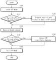
도 4는 본 발명의 제 1 실시예에 따른 메모리 시스템의 OTP 블록의 프로그램 및 재프로그램 방지 동작들을 설명하기 위한 흐름도이다.4 is a flowchart illustrating program and reprogram protection operations of an OTP block of a memory system according to a first embodiment of the present invention.
플래시 메모리 장치 (120)의 OTP 블록 (OTPBLK)에는 단지 한번 데이터가 프로그램될 수 있다. 플래시 메모리 장치 (120)의 OTP 블록 (OTPBLK)에 데이터를 프로그램하기 위해서, 먼저, 호스트 (160)는 OTP 모드로 진입하는 데 필요한 명령 (이하, "OTP 명령"이라 칭함)을 인터페이스 장치 (140)로 출력한다 (S100). 인터페이스 장치 (140)의 호스트 인터페이스 (141)는 OTP 명령에 응답하여 OTP 액세스 명령을 발생하고, 플래시 인터페이스 (142)는 OTP 모드로의 진입을 알리는 명령을 플래시 메모리 장치 (120)로 출력한다. 플래시 메모리 장치 (120)의 명령 레지스터 및 제어 로직 (208)은 OTP 모드로의 진입을 알리는 명령에 응답하여 OTP 인에이블 신호 (OTP_EN)를 활성화시킨다. 이는 이후 입력된 블록 어드레스에 따라 메모리 블록들 (BLK0-BLKx)이 선택되지 않게 한다. 즉, OTP 모드에서 OTP 인에이블 신호 (OTP_EN)가 활성화됨에 따라, 메모리 블록들 (BLK0-BLKx)은 선택되지 않는 반면에 OTP 블록 (OTPBLK)은 선택된다.Data may be programmed only once in the OTP block OTPBLK of the
앞서 설명된 과정을 통해 OTP 모드가 설정되면, 호스트 (160)는 프로그램 명 령을 인터페이스 장치 (140)로 출력하고, 인터페이스 장치 (140)의 호스트 인터페이스 (141)는 프로그램 명령에 응답하여 OTP 프로그램 명령을 플래시 인터페이스 (142)로 출력한다. 플래시 인터페이스 (142)는 OTP 액세스 명령의 입력에 응답하여 OTP 락 상태 레지스터 (142a)의 값이 OTP 블록 (OTPBLK)이 프로그램되지 않았음을 나타내는 '0'인 지의 여부를 판별한다 (S110). 만약 OTP 락 상태 레지스터 (142a)의 값이 OTP 블록 (OTPBLK)이 프로그램되었음을 나타내는 '1'이면, 절차는 S130 단계로 진행한다. 만약 OTP 락 상태 레지스터 (142a)의 값이 '0'이면, OTP 블록에 보안 데이터 및 보호 데이터가 프로그램된다 (S120). OTP 락 상태 레지스터 (142a)의 값이 OTP 블록 (OTPBLK)이 프로그램되었지 않았음을 나타내는 '0'일 때, 플래시 인터페이스 (142)는 OTP 프로그램 명령에 응답하여 정해진 타이밍에 따라 프로그램 명령, 어드레스 및 데이터를 플래시 메모리 장치 (120)로 출력한다. 플래시 메모리 장치 (120)의 명령 레지스터 및 제어 로직 (208)은 프로그램 명령에 응답하여 프로그램 동작에 필요한 고전압들을 발생하도록 고전압 발생 회로 (미도시됨)를 제어한다. 행 및 열 버퍼 회로들 (201, 202)은 명령 레지스터 및 제어 로직 (208)의 제어하에서 입출력 핀들 (IO0-IO15)을 통해 입력되는 어드레스들을 각각 래치한다.When the OTP mode is set through the above-described process, the
OTP 블록 (OTPBLK)에 대응하는 행 디코더 (OTPRD)는 행 버퍼 회로 (201)에 입력된 어드레스 중 행 어드레스 (RA)에 응답하여 OTP 블록 (OTPBLK)의 페이지들 중 하나를 선택한다. 이때, 앞서 설명된 바와 같이, 행 디코더들 (BLK0-BLKx)이 OTP 인에이블 신호 (OTPEN)에 의해서 비활성화되기 때문에, 메모리 블록들 (BLK0-BLKx)은 선택되지 않는다. 입출력 핀들 (IO0-IO15)을 통해 워드 단위로 순차적으로 입력되는 데이터는 열 게이트 회로 (206)를 통해 데이터 래치 및 감지 증폭 회로 (205)에 로드된다. 데이터 래치 및 감지 증폭 회로 (205)에 로드된 프로그램될 데이터는 잘 알려진 방식에 따라 OTP 블록 (OTPBLK)의 메인 영역에 프로그램된다. 이와 동시에, OTP 블록 (OTPBLK)의 스페어 영역에는 OTP 블록 (OTPBLK)이 프로그램되었음을 알리는 '00'의 보호 데이터 정보가 저장될 것이다. 이에 반해서, OTP 블록 (OTPBLK)이 프로그램되었음을 알리는 '00'의 보호 데이터 정보는 OTP 블록 (OTPBLK)의 메인 영역이 프로그램된 후에 OTP 블록 (OTPBLK)의 스페어 영역에 저장될 수 있다.The row decoder OTPRD corresponding to the OTP block OTPBLK selects one of the pages of the OTP block OTPBLK in response to the row address RA among the addresses input to the
OTP 블록 (OTPBLK)에 보안 데이터 및 보호 데이터 정보를 프로그램하는 동작이 종료되면, 호스트 (160)는 OTP 모드를 빠져나오기 위해서 리세트 명령을 인터페이스 장치 (140)로 출력한다 (S130). 플래시 인터페이스 (142)는 호스트 인터페이스 (141)로부터 리세트 명령가 입력될 때 OTP 락 상태 레지스터 (142a)의 값이 OTP 블록 (OTPBLK)이 프로그램되지 않았음을 나타내는 '0'인 지의 여부를 판별한다 (S140). 만약 OTP 락 상태 레지스터 (142a)의 값이 '1'이면, 절차는 S160 단계로 진행한다. 만약 OTP 락 상태 레지스터 (142a)의 값이 '0'이면, OTP 락 상태 레지스터 (142a)는 업 데이트된다 (S150). 구체적으로, 플래시 인터페이스 (142)는 OTP 블록 (OTPBLK)의 스페어 영역에 저장된 보호 데이터 정보가 읽혀지도록 플래시 메모리 장치 (120)로 읽기 명령을 출력한다. 플래시 인터페이스 (142)는 읽혀진 보호 데이터 정보가 '00'일 때 OTP 락 상태 레지스터 (142a)에 '1'의 OTP 락 상태 정보를 저장한다. 즉, OTP 락 상태 레지스터 (142a)가 업 데이트된다. 이후, 플래시 인 터페이스 (142)가 플래시 메모리 장치 (120)로 리세트 명령을 출력함으로써 OTP 모드가 종료된다 (S160). 즉, OTP 인에이블 신호 (OTP_EN)가 비활성화된다.When the operation of programming the security data and the protection data information in the OTP block OTPBLK ends, the
플래시 인터페이스 (142)의 OTP 락 상태 레지스터 (142a)에 저장된 OTP 락 상태 정보는 전원이 꺼지면 소멸되기 때문에, 전원이 인가될 때마다 OTP 락 상태 정보가 OTP 락 상태 레지스터 (142a)에 업 데이터되어야 한다. 구체적으로 설명하면, 전원이 켜지면, 플래시 인터페이스 (142)는 앞서 설명된 것과 동일한 방식으로 플래시 메모리 장치 (120)를 OTP 모드로 설정하고, OTP 블록 (OTPBLK)의 스페어 영역에 저장된 보호 데이터 정보가 읽혀지도록 플래시 메모리 장치 (120)로 읽기 명령을 출력한다. 플래시 인터페이스 (142)는 읽혀진 보호 데이터 정보가 '00'일 때 OTP 락 상태 레지스터 (142a)에 '1'의 OTP 락 상태 정보를 저장한다. 즉, OTP 락 상태 레지스터 (142a)가 업 데이트된다.Since the OTP lock status information stored in the OTP
일단 OTP 블록 (OTPBLK)이 프로그램되면, OTP 모드에서 OTP 블록 (OTPBLK)을 재프로그램하는 것은 불가능하다. 구체적으로 설명하면, OTP 모드에서 호스트 (160)로부터 프로그램 명령이 인터페이스 장치 (140)로 인가되면, 호스트 인터페이스 (141)는 플래시 인터페이스 (142)로 OTP 프로그램 명령을 출력한다. 플래시 인터페이스 (142)에 OTP 프로그램 명령이 인가되면, 플래시 인터페이스 (142)는 OTP 락 상태 레지스터 (142a)에 '1'의 OTP 락 상태 정보가 저장되어 있는 지의 여부를 판별한다. 만약 OTP 락 상태 레지스터 (142a)에 '1'의 OTP 락 상태 정보가 저장되어 있으면, OTP 프로그램 모드는 설정되지 않는다. 따라서, OTP 블록 (OTPBLK)은 재프로그램되지 않는다. 이때, 인터페이스 장치 (140)는 호스트 (160)에 OTP 프로 그램 모드의 진입이 실패하였음을 알릴 수 있다.Once the OTP block (OTPBLK) is programmed, it is impossible to reprogram the OTP block (OTPBLK) in the OTP mode. Specifically, if a program command is applied from the
일단 OTP 블록 (OTPBLK)이 프로그램되면, OTP 블록의 재프로그램 과정과 마찬가지로, 프로그램된 OTP 블록을 소거하는 것 역시 불가능하다. 구체적으로 설명하면, OTP 모드에서 호스트 (160)로부터 소거 명령이 인터페이스 장치 (140)로 인가되면, 호스트 인터페이스 (141)는 플래시 인터페이스 (142)로 OTP 소거 명령을 출력한다. 플래시 인터페이스 (142)에 OTP 소거 명령이 인가되면, 플래시 인터페이스 (142)는 OTP 락 상태 레지스터 (142a)에 '1'의 OTP 락 상태 정보가 저장되어 있는 지의 여부를 판별한다. 만약 OTP 락 상태 레지스터 (142a)에 '1'의 OTP 락 상태 정보가 저장되어 있으면, OTP 소거 모드는 설정되지 않는다. 따라서, OTP 블록 (OTPBLK)은 소거되지 않는다. 이때, 인터페이스 장치 (140)는 호스트 (160)에 OTP 모드의 진입이 실패하였음을 알릴 수 있다. 종래 기술에서 설명된 바와 같이, OTP 블록 (OTPBLK)의 소거 동작을 방지하기 위해서 별도의 퓨즈 옵션이 행 디코더에 사용되었다. 하지만, 본 발명의 경우, 행 디코더 (OTPRD)에 별도의 퓨즈 옵션 (미도시됨)을 사용하지 않고 OTP 블록 (OTPBLK)의 소거 동작을 방지할 수 있다.Once the OTP block (OTPBLK) is programmed, it is also impossible to erase the programmed OTP block, as is the reprogramming process of the OTP block. Specifically, when the erase command is applied from the
본 발명에 따른 메모리 시스템의 경우, OTP 블록 (OTPBLK)이 프로그램되었는 지의 여부를 판별하는 것은 OTP 블록 (OTPBLK)의 스페어 영역에 저장된 보호 데이터 정보를 읽지 않고 수행될 수 있다. 예를 들면, 호스트 (160)가 인터페이스 장치 (140)에 OTP 블록 (OTPBLK)의 보호 데이터 정보를 요청할 때, OTP 락 상태 레지스터 (142a)에 저장된 OTP 락 상태 정보가 호스트 (160)로 출력된다. 따라서, OTP 블록 (OTPBLK)의 스페어 영역에 저장된 보호 데이터 정보를 읽지 않고 OTP 블록 (OTPBLK)이 프로그램되었는 지의 여부를 판별하는 것이 가능하다.In the case of the memory system according to the present invention, determining whether the OTP block OTPBLK is programmed may be performed without reading the protection data information stored in the spare area of the OTP block OTPBLK. For example, when the
도 5는 본 발명의 제 2 실시예에 따른 메모리 시스템을 개략적으로 보여주는 블록도이다. 도 5에서, 도 1에 도시된 것과 동일한 기능을 수행하는 구성 요소들은 동일한 참조 번호들로 표기되며, 그것에 대한 설명은 그러므로 생략된다.5 is a block diagram schematically illustrating a memory system according to a second embodiment of the present invention. In Fig. 5, components performing the same functions as those shown in Fig. 1 are denoted by the same reference numerals, and description thereof is therefore omitted.
본 발명의 제 1 실시예에 따른 메모리 시스템의 경우, 앞서 설명된 바와 같이, OTP 블록이 프로그램되었는 지의 여부를 나타내는 보호 데이터 정보와 함께 보안 데이터가 OTP 블록에 저장된다. 이와 더불어, 본 발명의 제 2 실시예에 따른 메모리 시스템의 경우, OTP 블록 (도면에는, "OTPBLK"로 표기됨)에는 패키지 레벨에서 얻어진 테스트 정보 (예를 들면, 동작 주파수)가 저장된다. 테스트 정보는 보안 데이터 및 보호 데이터 정보가 저장되기 이전에 패키지 테스트 레벨에서 OTP 블록의 특정 어드레스 영역 (예를 들면, OTP 블록의 메인 영역 또는 스페어 영역)에 저장될 것이다.In the memory system according to the first embodiment of the present invention, as described above, the secure data is stored in the OTP block together with the protection data information indicating whether the OTP block is programmed. In addition, in the memory system according to the second embodiment of the present invention, test information (for example, operating frequency) obtained at the package level is stored in an OTP block (denoted as "OTPBLK" in the drawing). The test information will be stored in a specific address area of the OTP block (eg, main area or spare area of the OTP block) at the package test level before the secure data and protected data information are stored.
계속해서 도 5를 참조하면, 인터페이스 장치 (140)는 호스트 인터페이스 (141), 플래시 인터페이스 (142), 그리고 POR 읽기 인에이블 신호 발생 회로 (143)를 포함한다. 도 5에 도시된 호스트 인터페이스 (141) 및 플래시 인터페이스 (142)는 OTP 모드에서 도 1에 도시된 것과 동일한 동작하며, 그것에 대한 설명은 그러므로 생략된다. POR 읽기 인에이블 신호 발생 회로 (143)는 파워-업시 POR 읽기 인에이블 신호 (POR_READ)를 발생하고, 플래시 인터페이스 (142)는 POR 읽기 인에이블 신호 (POR_READ)에 응답하여 POR 읽기 모드를 알리는 명령을 플래시 메모리 (120)로 출력한다. 이후, 플래시 인터페이스 (142)는 POR 읽기 명령과 함께 어드레스를 플래시 메모리 (120)로 출력한다. POR 읽기 명령과 함께 플래시 메모리 (120)로 전송되는 어드레스는 테스트 정보가 저장된 영역을 지정하기 위한 어드레스이다. 플래시 메모리 (120)는 POR 읽기 명령에 응답하여 OTP 블록의 테스트 정보를 읽고, 읽혀진 테스트 정보를 인터페이스 장치 (140)로 출력한다. 인터페이스 장치 (140)의 플래시 인터페이스 (142)는 플래시 메모리 (120)로부터 출력된 테스트 정보를 레지스터 (142b)에 저장한다. 호스트 (160)가 레지스터 (142b)에 저장된 테스트 정보를 인터페이스 장치 (140)에 요청할 때, 인터페이스 장치 (140)는 호스트 (160)의 요청에 따라 레지스터 (142b)의 테스트 정보를 호스트 인터페이스 (141)를 통해 호스트 (160)로 출력한다.5, the
앞서의 설명에 따르면, 본 발명의 제 2 실시예에 따른 메모리 시스템의 경우, 파워-업시 수행되는 테스트 정보 읽기 동작은 호스트 (160)로부터의 명령없이 인터페이스 (140)의 제어 하에 자동적으로 수행된다.According to the foregoing description, in the memory system according to the second embodiment of the present invention, a test information read operation performed at power-up is automatically performed under the control of the
도 5에 있어서, 플래시 인터페이스 (142)에 존재하는 레지스터들 (142a, 142b)은 개별적으로 구현되어 있다. 하지만, 레지스터들 (142a, 142b)이 OTP 락 상태 정보 및 테스트 정보를 저장하도록 하나의 레지스터로 구현될 수 있음은 이 분야의 통상적인 지식을 습득한 자들에게 자명하다.5, the
도 6 및 도 7은 도 5에 도시된 POR 읽기 인에이블 신호 발생 회로의 실시예들을 개략적으로 보여주는 블록도들이다.6 and 7 are block diagrams schematically illustrating embodiments of the POR read enable signal generation circuit illustrated in FIG. 5.
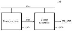
도 6을 참조하면, POR 읽기 인에이블 신호 발생 회로 (143)는 파워 온 리세트 회로 (143a)와 신호 발생기 (143b)를 포함한다. 파워 온 리세트 회로 (143a)는 파워-업시 전원 전압이 소정의 전압에 도달하였는 지의 여부를 검출하며, 그 결과로서 파워 온 리세트 신호 (POR)를 발생한다. 신호 발생기 (143b)는 파워 온 리세트 신호 (POR)에 응답하여 POR 읽기 인에이블 신호 (POR_READ)를 발생한다. POR 읽기 인에이블 신호 (POR_READ)는 파워 온 리세트 신호 (POR)가 활성화되고 소정 시간이 경과한 후에 생성된다. 여기서, 소정 시간은 파워-업시 전원 전압 (Vcc)이 소정 전압에서 충분히 목표 전압 (full Vcc)까지 증가하는 데 필요한 시간이다. 신호 발생기 (143b)는 이 분야에 잘 알려진 발진기로 구현된다.Referring to FIG. 6, the POR read enable
예시적인 파워 온 리세트 회로들이 U.S. Patent No. 6,346,834에 "POWER ON RESET CIRCUIT"라는 제목으로 그리고 U.S. Patent No. 6,204,703에 "POWER ON RESET CIRCUIT WITH POWER NOISE IMMUNITY"라는 제목으로 각각 개시되어 있으며, 레퍼런스로 포함된다.Exemplary power-on reset circuits include U.S. Patent No. 6,346,834 entitled "POWER ON RESET CIRCUIT" and U.S. Patent No. 6,204,703, each entitled "POWER ON RESET CIRCUIT WITH POWER NOISE IMMUNITY," and are incorporated by reference.
도 6에 도시된 것과 달리, POR 읽기 인에이블 신호 발생 회로 (143)는, 도 7에 도시된 바와 같이, 앞서 설명된 파워 온 리세트 회로만을 이용하여 구현될 수 있다.Unlike in FIG. 6, the POR read enable
본 발명의 제 2 실시예에 따른 메모리 시스템의 동작이 도 2, 도 5 내지 도 7을 참조하여 이하 상세시 설명될 것이다.The operation of the memory system according to the second embodiment of the present invention will be described in detail below with reference to FIGS. 2 and 5 to 7.
메모리 시스템 (100)에 전원이 공급되면, 인터페이스 장치 (140)의 POR 읽기 인에이블 신호 발생 회로 (143)는 POR 읽기 인에이블 신호 (POR_READ)를 발생한다. 플래시 인터페이스 (142)는 POR 읽기 인에이블 신호 (POR_READ)에 응답하여 POR 읽기 모드를 나타내는 명령을 플래시 메모리 (120)로 출력한다. 도 2에 도시된 플래 시 메모리 (120)의 명령 레지스터 및 제어 로직 (208)은 POR 읽기 명령가 입력될 때 OTP 인에이블 신호 (OTP_EN)를 활성화시킨다. OTP 인에이블 신호 (OTP_EN)는 메모리 블록들 (BLK0-BLKx)에 각각 대응하는 행 디코더들 (RD0-RDi)과 OTP 블록 (OTPBLK)에 대응하는 행 디코더 (OTPRD)에 인가된다. OTP 인에이블 신호 (OTP_EN)가 활성화될 때, 행 디코더들 (RD0-RDi)은 행 버퍼 회로 (201)로부터의 블록 및 행 어드레스들 (BA, RA)에 관계없이 비활성화된다. 즉, OTP 인에이블 신호 (OTP_EN)가 활성화될 때, 메모리 블록들 (BLK0-BLKx)은 대응하는 행 디코더들 (RD0-RDi)에 의해서 선택되지 않는다. 이에 반해서, OTP 인에이블 신호 (OTP_EN)가 활성화될 때, 행 디코더 (OTPBLK)는 행 버퍼 회로 (201)로부터 출력되는 행 어드레스 (RA)에 응답하여 OTP 블록 (OTPBLK)의 페이지들/행들 중 하나를 선택할 것이다.When power is supplied to the
플래시 인터페이스 (142)는 POR 읽기 모드를 나타내는 명령에 이어 POR 읽기 명령과 함께 어드레스를 플래시 메모리 (120)로 출력한다. 플래시 메모리 (120)는 OTP 인에이블 신호 (OTP_EN)가 활성화된 후 POR 읽기 명령이 입력되면, OTP 블록 (OTPBLK)의 읽기 동작은 낸드 플래시 메모리 장치의 잘 알려진 방식에 따라 수행될 것이다. 좀 더 구체적으로 설명하면 다음과 같다.The
도 2의 행 버퍼 회로 (201)는 명령 레지스터 및 제어 로직 (208)의 제어 하에 입출력 핀들 (IO0-IO15)을 통해 입력되는 행 어드레스를 입력받고, 열 버퍼 회로 (202)는 명령 레지스터 및 제어 로직 (208)의 제어 하에 입출력 핀들 (IO0-IO15)을 통해 입력되는 열 어드레스를 입력받는다. 행 디코더 (OTPBLK)는 행 버퍼 회로 (201)로부터의 어드레스에 응답하여 OTP 블록의 워드 라인들/페이지들 중 하 나를 선택한다. 데이터 래치 및 감지 증폭 회로 (205)는 선택된 OTP 블록에 저장된 데이터 (즉,테스트 데이터 정보)를 감지하고, 감지된 데이터를 래치한다. 그 다음에, 열 디코더 회로 (204)는 열 버퍼 회로 (202)로부터 출력되는 열 어드레스에 응답하여 열 선택 신호들을 발생하며, 열 게이트 회로 (206)는 열 디코더 회로 (204)로부터의 열 선택 신호들에 응답하여 선택된 OTP 블록의 열들 (또는 페이지 버퍼들)을 워드 단위로 순차적으로 선택한다. 그렇게 선택된 페이지 버퍼들에 래치된 데이터는 명령 레지스터 및 제어 로직 (208)의 제어하에 입출력 핀들 (IO0-IO15)을 통해 외부로 출력된다. 결과적으로, 읽기 동작의 결과로서 테스트 정보는 플래시 인터페이스 (142)의 레지스터 (142b)에 저장될 것이다. 호스트 (160)가 레지스터 (142b)에 저장된 테스트 정보를 인터페이스 장치 (140)에 요청할 때, 인터페이스 장치 (140)는 호스트 (160)의 요청에 따라 레지스터 (142b)의 테스트 정보를 호스트 인터페이스 (141)를 통해 호스트 (160)로 출력한다.The
결과적으로, 본 발명의 제 2 실시예에 따른 메모리 시스템의 경우, 파워-업시 OTP 블록에서 테스트 정보를 읽는 동작은 호스트 (160)로부터의 명령없이 인터페이스 (140)의 제어 하에 자동적으로 수행된다.As a result, in the memory system according to the second embodiment of the present invention, the operation of reading test information in the OTP block at power-up is automatically performed under the control of the
본 발명의 제 2 실시예에 따른 메모리 시스템의 경우, 동작 주파수와 같은 테스트 정보를 OTP 블록에 저장함으로써 수율을 향상시킬 수 있다. 예를 들면, 웨이퍼에 형성되는 다수의 칩들은 동일한 조건에서 제조되더라도, 원하는 동작 주파수 범위에 속하지 않는 칩(들)이 존재할 수 있다. 그러한 칩들의 테스트 동작 (특히, 각 칩의 동작 주파수를 측정하는 동작)은 일반적으로 패키지 레벨에서 수행된 다. 만약 임의의 칩의 측정 동작 주파수가 원하는 동작 주파수 범위에 속하지 않으면, 즉, 제작된 칩의 동작 주파수가 원하는 동작 주파수 범위에 속하지 않기 때문에 그러한 칩은 폐기될 것이다. 하지만, 임의의 칩의 측정 동작 주파수가 원하는 동작 주파수 범위에 속하지 않더라도, 측정된 동작 주파수의 테스트 정보를 OTP 블록 내에 저장함으로써 원하는 동작 주파수 범위에 속하지 않는 칩(들)은 앞서 언급된 테스트 정보에 의거하여 다른 동작 주파수 범위에 속하는 칩(들)로 분류될 수 있다. 이는 수율이 향상될 수 있음을 의미한다.In the case of the memory system according to the second embodiment of the present invention, the yield can be improved by storing test information such as an operating frequency in the OTP block. For example, even if multiple chips formed on a wafer are manufactured under the same conditions, there may be chip (s) that do not fall within the desired operating frequency range. Test operations of such chips (in particular, the operation frequency of each chip) are generally performed at the package level. If the measurement operating frequency of any chip does not fall within the desired operating frequency range, that is, the chip will be discarded because the operating frequency of the fabricated chip does not fall within the desired operating frequency range. However, even if the measured operating frequency of any chip does not belong to the desired operating frequency range, the chip (s) not belonging to the desired operating frequency range by storing the test information of the measured operating frequency in the OTP block are based on the aforementioned test information. Can be classified into chip (s) belonging to different operating frequency ranges. This means that the yield can be improved.
제 2 실시예에 따른 메모리 시스템의 경우, POR 읽기 모드가 설정된 후 테스트 정보가 읽혀진다. 이에 반해서, POR 읽기 인에이블 신호가 활성화된 후, 바로 POR 읽기 동작이 수행될 수 있다. 예를 들면, 플래시 인터페이스 (142)는 POR 읽기 인에이블 신호 (POR_READ)의 활성화에 응답하여 POR 읽기 명령과 함께 어드레스 (테스트 정보가 저장된 영역을 지정하기 위한 어드레스)를 플래시 메모리 (120)에 전송한다. 그 다음에, 플래시 메모리 (120)는 POR 읽기 명령에 응답하여 OTP 인에이블 신호 (OTP_EN)를 활성화시킨다. 이는 행 디코더 (OTPRD)만이 활성화됨을 의미한다. 이후, 앞서 설명된 바와 같이, OTP 블록에 대한 읽기 동작이 수행되고, 그렇게 읽혀진 테스트 정보가 플래시 인터페이스 (142)의 레지스터 (142b)에 저장될 것이다.In the memory system according to the second embodiment, test information is read after the POR read mode is set. In contrast, the POR read operation may be performed immediately after the POR read enable signal is activated. For example, the
본 발명에 따른 메모리 시스템에 있어서, 설계 변경에 따라, OTP 블록에 저장된 보호 데이터 정보 및 테스트 정보는 OTP 모드 및 POR 읽기 모드에서 각각 연속적으로 읽혀지거나, POR 읽기 모드에서 동시에 또는 개별적으로 읽혀질 수 있다. 또는, OTP 블록에 저장된 보호 데이터 정보 및 테스트 정보는 OTP 모드에서 동시에 또는 개별적으로 읽혀질 수 있다.In the memory system according to the present invention, according to a design change, the protected data information and the test information stored in the OTP block may be read continuously in the OTP mode and the POR read mode, or simultaneously or separately in the POR read mode. Alternatively, the protected data information and the test information stored in the OTP block may be read simultaneously or separately in the OTP mode.
이상에서, 본 발명에 따른 회로의 구성 및 동작을 상기한 설명 및 도면에 따라 도시하였지만, 이는 예를 들어 설명한 것에 불과하며 본 발명의 기술적 사상 및 범위를 벗어나지 않는 범위 내에서 다양한 변화 및 변경이 가능함은 물론이다.In the above, the configuration and operation of the circuit according to the present invention has been shown in accordance with the above description and drawings, but this is only an example, and various changes and modifications can be made without departing from the spirit and scope of the present invention. Of course.
상술한 바와 같이, 레지스터에 저장된 OTP 락 상태 정보에 따라 OTP 모드의 진입을 제어함으로써 프로그램된 OTP 블록의 재프로그램/소거 동작을 원천적으로 차단할 수 있다. 이는 OTP 블록에 저장된 데이터가 안전하게 보존될 수 있음을 의미한다. 또한, OTP 블록을 번거롭게 액세스하지 않고, OTP 블록이 프로그램되었는 지의 여부를 확인할 수 있다. 더욱이, OTP 블록의 소거 동작을 차단하기 위한 별도의 퓨즈 옵션없이 OTP 블록이 소거되는 것을 차단할 수 있다.As described above, the reprogramming / erase operation of the programmed OTP block can be blocked by controlling the entry of the OTP mode according to the OTP lock state information stored in the register. This means that the data stored in the OTP block can be safely preserved. It is also possible to check whether the OTP block has been programmed without accessing the OTP block cumbersomely. Moreover, the OTP block can be prevented from being erased without a separate fuse option for blocking the erase operation of the OTP block.
삭제delete
Claims (38)
Translated fromKoreanPriority Applications (3)
| Application Number | Priority Date | Filing Date | Title |
|---|---|---|---|
| DE102004056088ADE102004056088B4 (en) | 2003-11-13 | 2004-11-12 | Storage system with flash memory |
| JP2004329709AJP2005149715A (en) | 2003-11-13 | 2004-11-12 | Memory system having flash memory including OTP block |
| US10/990,307US7031188B2 (en) | 2003-11-13 | 2004-11-15 | Memory system having flash memory where a one-time programmable block is included |
Applications Claiming Priority (2)
| Application Number | Priority Date | Filing Date | Title |
|---|---|---|---|
| KR1020030080301 | 2003-11-13 | ||
| KR20030080301 | 2003-11-13 |
Publications (2)
| Publication Number | Publication Date |
|---|---|
| KR20050046520A KR20050046520A (en) | 2005-05-18 |
| KR100632939B1true KR100632939B1 (en) | 2006-10-12 |
Family
ID=37245896
Family Applications (1)
| Application Number | Title | Priority Date | Filing Date |
|---|---|---|---|
| KR1020040031117AExpired - Fee RelatedKR100632939B1 (en) | 2003-11-13 | 2004-05-03 | Memory system having flash memory where otp block is included |
Country Status (1)
| Country | Link |
|---|---|
| KR (1) | KR100632939B1 (en) |
Families Citing this family (12)
| Publication number | Priority date | Publication date | Assignee | Title |
|---|---|---|---|---|
| TWI308692B (en)* | 2005-10-26 | 2009-04-11 | Sunplus Technology Co Ltd | Programmable memory and accessing method of the same |
| KR100773398B1 (en)* | 2005-12-14 | 2007-11-05 | 삼성전자주식회사 | Phase Change Memory Device with OTP Cell Array |
| KR100816160B1 (en)* | 2005-12-15 | 2008-03-21 | 주식회사 하이닉스반도체 | One-Time Programmable Memory Devices and Programming Methods |
| KR100850203B1 (en) | 2006-04-28 | 2008-08-04 | 삼성전자주식회사 | Display driving integrated circuit and driving circuit control signal output method saving driving circuit control signal output mode in the non-volatile memory, and display driving integrated circuit including wires disposed on the top layer and manufacturing method thereof |
| KR100739257B1 (en)* | 2006-05-16 | 2007-07-12 | 주식회사 하이닉스반도체 | Flash memory devices |
| KR100833189B1 (en)* | 2006-11-03 | 2008-05-28 | 삼성전자주식회사 | How to set configuration information of nonvolatile memory device and nonvolatile memory device |
| US9767319B2 (en)* | 2007-04-17 | 2017-09-19 | Avago Technologies General Ip (Singapore) Pte. Ltd. | Method and apparatus of secure authentication for system on chip (SoC) |
| WO2010104219A1 (en)* | 2009-03-09 | 2010-09-16 | 주식회사 안철수연구소 | Data protecting method in memory and apparatus using the same |
| KR20110102734A (en) | 2010-03-11 | 2011-09-19 | 삼성전자주식회사 | Nonvolatile Semiconductor Memory Device with OTP Lock Bit Register |
| KR102139327B1 (en)* | 2012-11-15 | 2020-07-29 | 삼성전자주식회사 | Non-volatile memory device and method of operating the same |
| US12153812B2 (en) | 2021-11-12 | 2024-11-26 | Samsung Electronics Co., Ltd. | Memory device including one-time programmable block and operation method thereof |
| US12238925B2 (en) | 2022-08-11 | 2025-02-25 | Samsung Electronics Co., Ltd. | Semiconductor memory device capable of expanding bank capacity adaptively to package size and method of designing the same |
- 2004
- 2004-05-03KRKR1020040031117Apatent/KR100632939B1/ennot_activeExpired - Fee Related
Also Published As
| Publication number | Publication date |
|---|---|
| KR20050046520A (en) | 2005-05-18 |
Similar Documents
| Publication | Publication Date | Title |
|---|---|---|
| US7031188B2 (en) | Memory system having flash memory where a one-time programmable block is included | |
| KR100666013B1 (en) | Nonvolatile semiconductor memory | |
| US7145799B2 (en) | Chip protection register unlocking | |
| US6751122B2 (en) | Nonvolatile semiconductor memory device | |
| US7466600B2 (en) | System and method for initiating a bad block disable process in a non-volatile memory | |
| US6445606B1 (en) | Secure poly fuse ROM with a power-on or on-reset hardware security features and method therefor | |
| US20070081377A1 (en) | Method and circuit for reading fuse cells in a nonvolatile memory during power-up | |
| KR100632939B1 (en) | Memory system having flash memory where otp block is included | |
| KR100374366B1 (en) | Non-volatile semiconductor memory device and method of manufacturing thereof | |
| KR100395770B1 (en) | Novolatile flash memory device usable as a boot-up memory in a system and method of operating the same | |
| US6400624B1 (en) | Configure registers and loads to tailor a multi-level cell flash design | |
| US6879518B1 (en) | Embedded memory with security row lock protection | |
| KR100648277B1 (en) | Flash memory device can reduce program time | |
| KR100590219B1 (en) | Nonvolatile Memory Devices Reduce Program Time | |
| KR100769102B1 (en) | Nonvolatile semiconductor memory device, method of erasing nonvolatile semiconductor memory device and testing method of nonvolatile semiconductor memory device | |
| US6842371B2 (en) | Permanent master block lock in a memory device | |
| EP0397194A2 (en) | Semiconductor memory device having two types of memory cell | |
| KR100903695B1 (en) | Information setting method of nonvolatile memory and nonvolatile memory |
Legal Events
| Date | Code | Title | Description |
|---|---|---|---|
| A201 | Request for examination | ||
| PA0109 | Patent application | St.27 status event code:A-0-1-A10-A12-nap-PA0109 | |
| PA0201 | Request for examination | St.27 status event code:A-1-2-D10-D11-exm-PA0201 | |
| P11-X000 | Amendment of application requested | St.27 status event code:A-2-2-P10-P11-nap-X000 | |
| P13-X000 | Application amended | St.27 status event code:A-2-2-P10-P13-nap-X000 | |
| R15-X000 | Change to inventor requested | St.27 status event code:A-3-3-R10-R15-oth-X000 | |
| R16-X000 | Change to inventor recorded | St.27 status event code:A-3-3-R10-R16-oth-X000 | |
| PG1501 | Laying open of application | St.27 status event code:A-1-1-Q10-Q12-nap-PG1501 | |
| PN2301 | Change of applicant | St.27 status event code:A-3-3-R10-R13-asn-PN2301 St.27 status event code:A-3-3-R10-R11-asn-PN2301 | |
| PN2301 | Change of applicant | St.27 status event code:A-3-3-R10-R13-asn-PN2301 St.27 status event code:A-3-3-R10-R11-asn-PN2301 | |
| D13-X000 | Search requested | St.27 status event code:A-1-2-D10-D13-srh-X000 | |
| D14-X000 | Search report completed | St.27 status event code:A-1-2-D10-D14-srh-X000 | |
| E902 | Notification of reason for refusal | ||
| PE0902 | Notice of grounds for rejection | St.27 status event code:A-1-2-D10-D21-exm-PE0902 | |
| T11-X000 | Administrative time limit extension requested | St.27 status event code:U-3-3-T10-T11-oth-X000 | |
| T11-X000 | Administrative time limit extension requested | St.27 status event code:U-3-3-T10-T11-oth-X000 | |
| P11-X000 | Amendment of application requested | St.27 status event code:A-2-2-P10-P11-nap-X000 | |
| P13-X000 | Application amended | St.27 status event code:A-2-2-P10-P13-nap-X000 | |
| E701 | Decision to grant or registration of patent right | ||
| PE0701 | Decision of registration | St.27 status event code:A-1-2-D10-D22-exm-PE0701 | |
| GRNT | Written decision to grant | ||
| PR0701 | Registration of establishment | St.27 status event code:A-2-4-F10-F11-exm-PR0701 | |
| PR1002 | Payment of registration fee | St.27 status event code:A-2-2-U10-U11-oth-PR1002 Fee payment year number:1 | |
| PG1601 | Publication of registration | St.27 status event code:A-4-4-Q10-Q13-nap-PG1601 | |
| PR1001 | Payment of annual fee | St.27 status event code:A-4-4-U10-U11-oth-PR1001 Fee payment year number:4 | |
| PR1001 | Payment of annual fee | St.27 status event code:A-4-4-U10-U11-oth-PR1001 Fee payment year number:5 | |
| FPAY | Annual fee payment | Payment date:20110830 Year of fee payment:6 | |
| PR1001 | Payment of annual fee | St.27 status event code:A-4-4-U10-U11-oth-PR1001 Fee payment year number:6 | |
| R18-X000 | Changes to party contact information recorded | St.27 status event code:A-5-5-R10-R18-oth-X000 | |
| FPAY | Annual fee payment | Payment date:20120831 Year of fee payment:7 | |
| PR1001 | Payment of annual fee | St.27 status event code:A-4-4-U10-U11-oth-PR1001 Fee payment year number:7 | |
| LAPS | Lapse due to unpaid annual fee | ||
| PC1903 | Unpaid annual fee | St.27 status event code:A-4-4-U10-U13-oth-PC1903 Not in force date:20130930 Payment event data comment text:Termination Category : DEFAULT_OF_REGISTRATION_FEE | |
| PC1903 | Unpaid annual fee | St.27 status event code:N-4-6-H10-H13-oth-PC1903 Ip right cessation event data comment text:Termination Category : DEFAULT_OF_REGISTRATION_FEE Not in force date:20130930 | |
| P22-X000 | Classification modified | St.27 status event code:A-4-4-P10-P22-nap-X000 | |
| P22-X000 | Classification modified | St.27 status event code:A-4-4-P10-P22-nap-X000 |